JP7026084B2 - How to make shoes - Google Patents
How to make shoesDownload PDFInfo
- Publication number
- JP7026084B2 JP7026084B2JP2019144402AJP2019144402AJP7026084B2JP 7026084 B2JP7026084 B2JP 7026084B2JP 2019144402 AJP2019144402 AJP 2019144402AJP 2019144402 AJP2019144402 AJP 2019144402AJP 7026084 B2JP7026084 B2JP 7026084B2
- Authority
- JP
- Japan
- Prior art keywords
- layer
- molding
- manufacturing
- fiber sheet
- last
- Prior art date
- Legal status (The legal status is an assumption and is not a legal conclusion. Google has not performed a legal analysis and makes no representation as to the accuracy of the status listed.)
- Active
Links
Images


Landscapes
- Footwear And Its Accessory, Manufacturing Method And Apparatuses (AREA)
Description
Translated fromJapanese本発明は、布製のアッパーを備えたシューズ(靴)、及び、このシューズの製造方法に関する。 The present invention relates to a shoe (shoe) provided with a cloth upper and a method for manufacturing the shoe.
特許文献1または特許文献2には、不織布を含むシューズに関して開示がある。
ここで、シューズを作製する際には、例えばアッパーを所定の形状に成形するために、アッパーを構成する布地を被せるためのラスト(靴型)が用いられる。 Here, when manufacturing shoes, for example, in order to form the upper into a predetermined shape, a last (last) for covering the fabric constituting the upper is used.
アッパーの成形に当たっては、ラストの形状に沿わせることが重要である。具体的に、発注者の足の形状から型取りしたラストの場合、発注者個人の足の形状に良く合わせることにより、カスタマイズに応用する点で重要であり、また、量産品のシューズのラストの場合、量産されたシューズの形状のばらつきをなくすことができる点で重要である。これら重要な点につき、例えば、足の外側部分でラストの表面に対して隙間ができるような成形であった場合、シューズ着用時に着用者の足は外側に動いてしまうから、ホールド性に欠けるものとなってしまう。また、できた隙間を詰め物等により埋めると、着用感が悪化することがある。 When molding the upper, it is important to follow the shape of the last. Specifically, in the case of the last modeled from the shape of the orderer's foot, it is important to apply it to customization by matching it well with the shape of the orderer's individual foot, and the last of mass-produced shoes. In this case, it is important in that it is possible to eliminate variations in the shape of mass-produced shoes. Regarding these important points, for example, if the outer part of the foot is molded so that there is a gap with respect to the surface of the last, the wearer's foot will move outward when the shoe is worn, so it lacks holdability. Will be. Further, if the created gap is filled with a padding or the like, the wearing feeling may be deteriorated.
ここで、特許文献1または2には、アッパーの成形とラストとの関係について特に言及がされていない。このため、アッパーの成形とラストとの関係については、従来、特に認識されていなかったと思われる。 Here,
そこで本発明は、成形時にラストの形状に沿いやすいアッパーを備えたシューズ、及び、このシューズの製造方法の提供を課題とする。 Therefore, it is an object of the present invention to provide a shoe provided with an upper that easily follows the shape of the last during molding, and a method for manufacturing the shoe.
本発明は、熱収縮性を有する糸を含み、かつ、内部空隙を有する編物または織物よりなる第1層と、前記第1層に積層され、不織布よりなる第2層と、を含み、前記第1層と前記第2層とがニードルパンチ加工により一体化された繊維シートよりなるアッパーを備えているシューズである。 The present invention includes a first layer made of a knitted fabric or a woven fabric containing a heat-shrinkable yarn and having internal voids, and a second layer laminated on the first layer and made of a non-woven fabric. A shoe having an upper made of a fiber sheet in which one layer and the second layer are integrated by needle punching.
この構成によれば、繊維シートが、熱収縮性を有する糸を含む第1層を備え、かつ、第1層が内部空隙を有することから、加熱によるアッパーの成形を行う際に、アッパーを構成する繊維シートが容易に変形するため、ラストの形状に沿わせやすい。 According to this configuration, since the fiber sheet includes a first layer containing a heat-shrinkable yarn and the first layer has an internal void, the upper is configured when the upper is formed by heating. Since the fiber sheet to be formed is easily deformed, it is easy to follow the shape of the last.
また本発明は、熱収縮性を有する糸を含み、内部空隙を有する編物または織物よりなる第1層と、前記第1層に積層され、不織布よりなる第2層と、を含むアッパーを備えたシューズの製造方法であって、当該製造方法は、前記第1層と前記第2層とを所定のサイズに裁断する裁断工程と、前記第1層と前記第2層とを重ねてニードルパンチ加工を施すことで繊維シートを作製する一体化工程と、前記繊維シートをアッパーに対応した形状に縫製した成形前アッパーを作製し、当該成形前アッパーをラストにかぶせる第1成形工程と、加熱により前記成形前アッパーを前記ラストの形状に沿わせるように変形させて成形後アッパーとする第2成形工程と、を含むシューズの製造方法である。 The present invention also comprises an upper comprising a heat-shrinkable thread, a first layer made of a knitted fabric or a woven fabric having internal voids, and a second layer laminated on the first layer and made of a non-woven fabric. A method for manufacturing shoes, in which the first layer and the second layer are cut to a predetermined size, and the first layer and the second layer are overlapped with each other for needle punching. The first molding step of producing a pre-molded upper in which the fiber sheet is sewn into a shape corresponding to the upper, and the pre-molded upper is put on the last, and the above-mentioned by heating. It is a method for manufacturing shoes including a second molding step of deforming a pre-molding upper so as to conform to the shape of the last to form a post-molding upper.
この構成によれば、ラストの形状に沿ったシューズを製造できる。 According to this configuration, shoes that follow the shape of the last can be manufactured.
本発明によると、加熱によるアッパーの成形を行う際に、ラストの形状に沿わせやすい。よって、成形時にラストの形状に沿いやすいアッパーを備えたシューズ、及び、このシューズの製造方法を提供できる。 According to the present invention, when molding the upper by heating, it is easy to follow the shape of the last. Therefore, it is possible to provide a shoe having an upper that easily follows the shape of the last during molding, and a method for manufacturing the shoe.
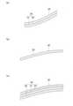
本発明につき、実施形態を図面とともに例示する。本実施形態のシューズ1の左右各片は、図1に示すように、主にソール2とアッパー3とを備え、ソール2に対してアッパー3が取り付けられている。アッパー3は少なくとも二層構造であって、図2(a)、図3に示すように、シート状の第1層31と、第1層31に積層されたシート状の第2層32とを含む。なお、以下で製造の途中段階(成形前後)のアッパー3について説明する際には、区別のために成形前アッパー3Aや成形後アッパー3Bとも表示することがある。 An embodiment of the present invention will be illustrated together with the drawings. As shown in FIG. 1, each of the left and right pieces of the
第1層31は、熱収縮性を有する糸311を含む。第1層31は、内部空隙312を有する編物(編地)または織物(織地)よりなる。編物における編み方は特に限定されないが、例えばラッセル編みやトリコット編みとできる。織物における織り方も特に限定されないが、例えば平織りや綾織りとできる。 The
第2層32は、不織布よりなる。不織布は、例えばポリエステル繊維を有するものとできる。第2層32の不織布は、繊維が絡み合っていることから、第1層31の内部空隙312に相当する内部空隙は有さない。 The
アッパー3において、第1層31は第2層32よりも内側(着用時において着用者の足に近い側であり、図2(a)における下側)に配置されている。つまり、第1層31が内層であり、第2層32は外層である。 In the upper 3, the
ここで、前記「内部空隙」とは、編物または織物を構成する糸等の繊維同士、または繊維の集合体同士の間に存在する空間のことである。また、一般的に編物または織物において、繊維が平面方向に延びるように配置されている場合、前記平面の法線方向に貫通する空間、または平面方向において分断された空間のことである。また、繊維の交差点のうち隣り合うもの同士で距離が保たれている場合には、複数の繊維の交差点に囲まれた空間である。なお、後述のように融着糸を用いる場合、アッパー3(成形前アッパー3A)に対する熱成形によって融着された後における繊維の交差点は固着状態となり、交差する繊維(糸)同士が固定される。前記「内部空隙」は、例えば、メッシュの目(図3において重なり合いの2枚目として示した、第1層31の織物における緯糸311と経糸313とにより形成される内部空隙312を参照)や、布地の目開き部分が該当する。本実施形態では、隣り合う繊維の交差点間の距離が1~5mmに設定される。または、編物または織物に占める、平面方向での空間率が15~30%に設定される。前記二つの条件は、いずれか一方を満たすよう設定することができる。 Here, the "internal void" is a space existing between fibers such as threads constituting a knitted fabric or a woven fabric, or between aggregates of fibers. Further, in general, in a knitted fabric or a woven fabric, when the fibers are arranged so as to extend in the plane direction, it means a space penetrating in the normal direction of the plane or a space divided in the plane direction. Further, when the distance between adjacent fiber intersections is maintained, the space is surrounded by a plurality of fiber intersections. When a fused yarn is used as described later, the intersections of the fibers after being fused to the upper 3 (upper 3A before molding) by thermoforming are in a fixed state, and the intersecting fibers (threads) are fixed to each other. .. The "internal void" may be, for example, a mesh mesh (see the
第1層31が内部空隙312を有することにより、熱収縮性を有する糸311の変形(収縮)、及び、これに伴う交差する糸313(図4(b)参照)の移動を内部空隙312の空間が許容する。よって、熱収縮性を有する糸311による第1層31の変形を内部空隙312の空間が阻害しない。従って、第1層31を設計通り変形させることができるので、熱収縮のための条件(加熱温度及び加熱時間等)を設定しやすい。 Since the
第1層31に含まれる熱収縮性を有する糸311は、図4(a)に略示するように、芯3111(内周部分)と鞘3112(外周部分)とが一体形成された芯鞘材よりなるものとできる。この糸311は熱により融着する融着糸であって、芯3111と鞘3112とで融点が異なっている。この糸311において、融点は芯3111よりも鞘3112の方が低い。このため、アッパー3を成形する際の成形前アッパー3Aに対する加熱により、糸311の全体を収縮させ、かつ、鞘3112の部分のみ融解させられる。このため、鞘3112による保形作用と、芯3111による弾性作用とが両立できる。この熱収縮性を有する糸311として、例えばポリエステル樹脂を含む糸、より詳しくは、ポリエステル系熱可塑性エラストマーからなる鞘芯材、また、芯3111がポリエステル系熱可塑性エラストマーからなり、鞘3112がポリアミド系熱可塑性エラストマーからなる鞘芯材等を用いることができる。 As shown in FIG. 4A, the heat-
また、第1層31は、経糸または緯糸のうち一方が熱収縮性を有する糸311である織物、または、10%以上が熱収縮性を有する糸311である編物で構成されることができる。織物の場合、熱収縮性を有する糸311(経糸または緯糸)は、アッパー3における幅方向Y(図1参照)に沿って配置される。なお、本願出願の時点では、熱収縮性を有する糸311は緯糸に用いられることが、(技術的には)一般的である。このため、熱収縮性を有する糸311が緯糸に用いられた場合の第1層31における織物の構成を図4(b)に示す。この構成によると、第1層31を加熱することにより、図4(c)に示すように緯糸311が長さ方向に収縮する(矢印で示した方向の収縮により、隣り合う経糸313,313同士の間隔が小さく変化する)。そして、芯鞘材よりなる糸311の鞘3112が溶融して経糸313に固着する(図4(d)に黒丸で示した固着箇所314)。このように第1層31が変形する。この変形を利用することで、アッパー3を所望の形状とするため、具体的にはラスト(靴型)4の形状に沿わせるための適切な成形が可能である。 Further, the
第1層31と第2層32とは、図5に示すように、二層構造を構成する各層31,32が重ね合された状態で多数の針(ニードル)Nを有するニードル装置を図示の方向Mに往復動させ、重なった各層31,32に多数の針針(ニードル)を繰り返し貫通させるニードルパンチ加工が施されて一体化された繊維シート3Sとなっている。このように別々の層である第1層31と第2層32とが一体化されて繊維シート3Sとされることで、第1層31と第2層32の色の組合せや、ニードルパンチ加工を施す位置の選定等により、繊維シート3Sのデザインの自由度を高められる。この繊維シート3Sは、アッパー3に対応した成形前アッパー3Aの形状とする縫製を行う前の状態で、例えばシート状または袋状に形成されている。前記「袋状」とは、図1(b)に示すアッパー3が備える履き口11となる部分に対応して開口が設けられた形状であり、一例として図3に示す形状である。 As shown in FIG. 5, the
繊維シート3Sが、熱収縮性を有する糸311を含む第1層31を備え、かつ、第1層31が内部空隙312を有する。この繊維シート3Sの構成により、加熱によるアッパー3の成形(熱成形)を行う際に、アッパー3を構成する繊維シート3Sが熱を受けた場合に容易に変形する。このため、ラスト4の形状(立体形状)に沿わせやすい。また、図5(a)に例示するニードルパンチ加工により、第1層31と第2層32とを強固に一体化できる。 The
このようにラスト4の形状に沿わせやすいことから、例えば、足の外側部分でラスト4の表面に対して隙間ができるような成形にならないので、シューズ着用時に着用者の足が動いてしまいにくく、ホールド性に優れる。また、できた隙間を詰め物や金具を用いることにより埋める必要がないから、着用感も良好である。 Since it is easy to follow the shape of the last 4 in this way, for example, the outer part of the foot does not form a gap with respect to the surface of the last 4, so that the wearer's foot does not easily move when wearing the shoe. , Excellent holdability. Further, since it is not necessary to fill the created gap by using padding or metal fittings, the wearing feeling is also good.
また、第1層31が第2層32よりも内側に配置されていることから、熱収縮性を有する糸311を含む第1層31が、ラスト4にかぶせられた際にラスト4の表面に近い内側に位置することになるので、繊維シート3Sをラスト4にかぶせて熱成形を行う際、第1層31が第2層32よりも内側に配置されていない構成に比べると、第1層31をラスト4に近い位置とできるので、よりラスト4に沿わせやすい。 Further, since the
なおここでは、第1層31が第2層32よりも内側に配置されていることを例示した。しかし、各層の内外関係はこれに限定されず、逆の配置、つまり、第1層31が第2層32よりも外側に配置されていてもよい。 Here, it is exemplified that the
繊維シート3Sは、図5(b)に示すように、ニードルパンチ加工が施された加工部3S1と、施されていない隙間形成部3S2(二点鎖線で図示した部分)とを備えることができる。隙間形成部3S2では、第1層31と第2層32とが一体化されないため、第1層31と第2層32との間に隙間(空間)を形成できる。この隙間形成部3S2が有する隙間(空間)には、クッション材(糸、綿、フォーム材)または補強材を挿入できる。クッション材を挿入する位置は、例えば、履き口やシュータンの位置である。また、補強材を挿入する位置は、例えば、ハトメ部、つま先部、ヒール部である。これにより、隙間形成部3S2に所望の特性を付与できる。ただし、隙間形成部3S2に何も挿入しないことも可能である。隙間形成部3S2への挿入物の有する特性に応じ、特性を繊維シート3Sに持たせることができる。また、繊維シート3Sが加熱される際の熱収縮量を挿入物によって調整することもできる。また、補強材を熱硬化樹脂で形成することにより、ラスト4の形状に沿った補強材を形成できる。また逆に、ラスト4に沿わせたくない場合には、補強材として、熱成形の温度では変形しない材料を選定するか、アッパー3の熱成形後に補強材を隙間形成部3S2に挿入することもできる。このように、繊維シート3Sが加工部3S1と隙間形成部3S2とを備えることにより、アッパー3の部位ごとに実現させる特性のコントロールをしやすく、所望の特性を持たせるようにできる。また、繊維シート3Sにおける加工部3S1及び隙間形成部3S2の形成範囲、形状を設定することによっても、繊維シート3Sの特性を調整することができる。 As shown in FIG. 5B, the
繊維シート3Sは、図2(c)、図3に示すように第1層31の内側に、不織布よりなる第3層33をさらに備えた三層構造とすることもできる。この場合の第3層33についても、第1層31に対し、ニードルパンチ加工が施されて、第1層31、第2層32、第3層33の三層が一体化されている。このように第3層33を備えたことにより、第3層33の材質及び層厚を設定することで、製造されたシューズ1に所望の特性を付与できる。第3層33は、第1層31に対して全面的に設けられることもできるし、部分的に設けられることもできる。部分的に設ける場合、例えば第3層33を、着用者の足が出入りする履き口11の周縁部を補強するために用いたり、ハトメを形成する部分の補強として用いたりすることができる。 As shown in FIGS. 2C and 3, the
アッパー3は、繊維シート3Sが縫製された後の状態で上下方向Z(図1参照)の上側に位置する本体部34と、本体部34の下端に連続する底面部35とを備えることができる。なお、アッパー3が本体部34だけを備え、底面部35を備えないものともできる。また、後述のように、作製した底面部35を後に除去する(本体部34から分離する)こともできる。 The upper 3 can include a
繊維シート3Sは、少なくとも本体部34の前足部分Fに含まれることができる。ここで前記「前足部分」とは、人体の足の骨格にて、図6において囲まれた部分、つまり、指骨の基節骨B1(小指については中節骨B2)から距骨B3及び踵骨B4のうち前部までの範囲であって、着用時にアッパー3の本体部34において着用者の骨格のうち前記範囲が一致する部分を指す。この前足部分Fは、着用感や着用時における着用者の運動能力に与える影響が大きい重要な部分である。従って、前足部分Fの形状をラスト4に対して確実に合わせることで、前記影響に対応した大きな効果を得ることができる。 The
前足部分Fに含まれる繊維シート3Sにおける第1層31の熱収縮率は、アッパー3における前後方向X(図1参照)よりも幅方向Y(図1参照)の方が高いものとできる。なお、前後方向Xは、アッパー3におけるつま先側の最前端と、かかと側の最後端とを結ぶ仮想線の延びる方向であって、幅方向Yは水平方向であって前後方向Xに直交する方向である。 The heat shrinkage of the
ここで、前足部分Fでは前後方向Xよりも幅方向Yの方が、着用者の足の表面の形状に対応し、アッパー3表面の湾曲が大きい。これに対し、前足部分Fで第1層31の熱収縮率を、幅方向Yにおけるものが前後方向Xにおけるものよりも高くなるような異方性をもって設定することにより、湾曲が大きい方向(幅方向Y)と高収縮の方向を一致させられるため、熱圧縮率が等方性をもって設定されたものに比べると、湾曲に沿わせやすいので、前足部分Fをラスト4に沿わせやすい。具体的に、第1層31において、アッパー3における前後方向Xの熱収縮率よりも幅方向Yの熱収縮率の方が2倍以上で設定されている。ちなみに、第2層32は不織布よりなり、この不織布を構成する繊維に熱収縮性は積極的に付与されていない。このため、繊維シート3Sとして一体化された場合の第2層32は、第1層31の熱収縮に追随して(つられて)変形することになる。後述する第3層33についても同様である。 Here, in the forefoot portion F, the width direction Y corresponds to the shape of the surface of the wearer's foot more than the front-back direction X, and the curvature of the upper 3 surface is larger. On the other hand, by setting the heat shrinkage of the
アッパー3が底面部35を備える場合、本体部34の少なくとも一部は図2(a)に示すように第1層31を備え、底面部35は図2(b)に示すように第1層31を備えない単層構造とできる。つまり、底面部35に熱収縮性を有する糸を含まないようにできる。このように構成することで、加熱による成形時に底面部35が変形しにくくなる。底面部35が変形しにくいようにすることで、ソール2に対する底面部35の位置合わせをしやすいため、ソール2とアッパー3の接着を正確にできる。 When the upper 3 includes the
一方、前記とは逆に、底面部35が第1層31を備えることもできる。この場合、図2(c)に示すように第1層31の内側に不織布よりなる第3層33をさらに備えることができる。この場合でも、第1層31と第3層33とは、ニードルパンチ加工が施されて一体化されていることが望ましい。このように構成することで、加熱による成形時に底面が変形しにくい。 On the other hand, contrary to the above, the
次に、前記構成のアッパー3、つまり、第1層31と、第1層31に積層された第2層32とを含むアッパー3を備えたシューズ1の製造方法について説明する。この製造方法は、裁断工程、一体化工程、第1成形工程、第2成形工程と、ソール取付工程を主に含む。なお、前記工程以外の工程を適宜付加することもできる。 Next, a method of manufacturing the
裁断工程では、シート状である第1層31と第2層32とを所定のサイズ及び形状に裁断し、本体部34及び底面部35を展開した、図7に示すような形状とする。一体化工程では、第1層31と第2層32とを重ねてニードルパンチ加工を施すことで繊維シート3Sを作製する。裁断工程と一体化工程はこの順序でなく、逆の順序でもよい。具体的には、第1層31と第2層32とを重ねてニードルパンチ加工を施すことで繊維シート3Sを作製し、その後に繊維シート3Sを所定のサイズ、形状に裁断してもよい。第1成形工程では、一体化工程で作製された繊維シート3Sをアッパー3に対応した形状に縫製した成形前アッパー3Aを作製し(図8参照)、この成形前アッパー3Aをラスト4にかぶせる(図9参照)。第2成形工程では、成形前アッパー3Aの周囲からの加熱により成形前アッパー3Aをラスト4の形状に沿わせるように変形させて成形後アッパー3B(図1参照)とする。温度と加熱時間は、成形前アッパー3Aの構成に合わせて適宜設定できる。第2成形工程において用いられる加熱手段はスチーム加熱である。図9に略示したように、例えば成形前アッパー3Aが加熱箱51の内部に収納され、加熱箱51の内面から放出される高温の蒸気52により加熱がなされる。このスチーム加熱により、成形前アッパー3Aの全体を均一に加熱することができる。このため、成形前アッパー3Aをラスト4に合わせて均一に変形させ、成形後アッパー3Bとすることができる。なお第2成形工程では、スチーム加熱のほか熱風加熱、温水加熱等を用いることもできる。また、成形前アッパー3Aに対する加熱を全体ではなく部分的に行うこともできる。ソール取付工程では、成形後アッパー3Bが別に作製されたソール2に、例えば接着により取り付けられる。なお、接着以外に、熱融着等によって第2成形工程と同時にソール取付工程を実施することもできる。 In the cutting step, the sheet-shaped
前述した一連の工程を経ることでシューズ1が製造される。なお、シュータンの形成、履き口11の加工、シューレース(靴紐)を通すためのハトメの取り付け、装飾部材やタグの取り付け、ロゴのプリント、インソール(中敷)の取り付けを前記各工程中、または全工程終了後に適宜行うことができる。各部材の取り付けに関してもニードルパンチを利用することができる。 The
成形前アッパー3Aが、上側に位置する本体部34と、本体部34の下端に連続する底面部35とを備える場合、第2成形工程において、底面部35には熱を加えないことができる。底面部35に熱を加えないようにするため、例えば、遮蔽板など、断熱性を有する治具を使用したり、底面に断熱性を有するラスト4を使用したりすることで、底面部35に及ぶ熱を低減できる。このようにすることで、加熱時に底面部35が変形しにくい。よって、接着工程における底面部35のソール2への接着が正確にできる。 When the pre-molding upper 3A includes a
また、前記とは別に、上側に位置する本体部34と、本体部34の下端に連続する底面部35とを備える場合、第2成形工程において、底面部35に熱を加え、第2成形工程の後に底面部35を除去する底面部除去工程を含むこともできる。底面部除去工程により、図7の右側に示した形状の底面部35が本体部34から分離され、成形後アッパー3Bの下部には貫通穴(図示しない)が形成されることになる。底面部除去工程を経た成形後アッパー3Bにおいて、前記貫通穴の縁部がソール2に取り付けられる。第2成形工程において成形前アッパー3Aをラスト4の形状に確実に沿わせ、その後に、ソール2に接着する際に加熱で収縮することによって硬くなる可能性のある底面部35を成形後アッパー3Bから除去することで、ソール2が加熱された底面部35の影響を受けることなく、適切な硬さのソール2を有するシューズ1を製造できる。 In addition to the above, when the
なお、前述のように底面部35には熱を加えない場合であっても、底面部35に接着剤を塗布すると底面部35が硬化してしまうことがある。このため、底面部35に熱を加えない場合に底面部除去工程を実施することも可能である。 Even when heat is not applied to the
前述の製造方法により、第2成形工程においてアッパー3の成形を行う際に、ラスト4の形状に沿わせやすいことから、ラスト4の形状に沿ったシューズ1を製造できる。 By the above-mentioned manufacturing method, when molding the upper 3 in the second molding step, it is easy to follow the shape of the last 4, so that the
ここで、本発明の実施形態に係る構成と奏する作用につきまとめる。本実施形態は、熱収縮性を有する糸を含み、かつ、内部空隙を有する編物または織物よりなる第1層と、前記第1層に積層され、不織布よりなる第2層と、を含み、前記第1層と前記第2層とがニードルパンチ加工により一体化された繊維シートよりなるアッパーを備えているシューズである。 Here, the configuration and the action to be performed according to the embodiment of the present invention will be summarized. The present embodiment includes a first layer made of a knitted fabric or a woven fabric containing a heat-shrinkable yarn and having internal voids, and a second layer laminated on the first layer and made of a non-woven fabric. A shoe having an upper made of a fiber sheet in which a first layer and the second layer are integrated by needle punching.
この構成によれば、繊維シートが、熱収縮性を有する糸を含む第1層を備え、かつ、第1層が内部空隙を有することから、加熱によるアッパーの成形を行う際に、アッパーを構成する繊維シートが容易に変形するため、ラストの形状に沿わせやすい。 According to this configuration, since the fiber sheet includes a first layer containing a heat-shrinkable yarn and the first layer has an internal void, the upper is configured when the upper is formed by heating. Since the fiber sheet to be formed is easily deformed, it is easy to follow the shape of the last.
また、前記第1層は前記第2層よりも内側に配置されているものとできる。 Further, the first layer may be arranged inside the second layer.
この構成によれば、熱収縮性を有する糸を含む第1層が、ラストにかぶせられた際にラストの表面に近い内側に位置することになるので、ラストにかぶせた際、よりラストに沿わせやすい。 According to this configuration, the first layer containing the heat-shrinkable yarn is located inside near the surface of the last when it is put on the last, so that when it is put on the last, it is closer to the last. Easy to make.
また、前記繊維シートは、前記第1層の内側に、不織布よりなる第3層をさらに備え、前記第1層と前記第3層とは、ニードルパンチ加工により一体化されているものとできる。 Further, the fiber sheet is further provided with a third layer made of a non-woven fabric inside the first layer, and the first layer and the third layer can be integrated by needle punching.
この構成によれば、第3層を備えたことにより、シューズに所望の特性を付与できる。 According to this configuration, by providing the third layer, it is possible to impart desired characteristics to the shoe.
また、前記アッパーは、上側に位置する本体部と、前記本体部の下端に連続する底面部とを備え、前記繊維シートは、少なくとも前記本体部の前足部分に含まれ、前記第1層の熱収縮率は、前記アッパーにおける前後方向よりも幅方向の方が高いものとできる。 Further, the upper includes a main body portion located on the upper side and a bottom surface portion continuous with the lower end of the main body portion, and the fiber sheet is included in at least the forefoot portion of the main body portion, and the heat of the first layer is provided. The shrinkage rate can be higher in the width direction than in the front-back direction in the upper.
この構成によれば、本体部の前足部分をラストに沿わせやすい。 According to this configuration, the forefoot portion of the main body can be easily aligned with the last.
また、前記本体部の少なくとも一部は、前記第1層を備え、前記底面部は、前記第1層を備えないものとできる。 Further, at least a part of the main body portion may be provided with the first layer, and the bottom surface portion may not be provided with the first layer.
この構成によれば、加熱による成形時に底面部が変形しにくい。 According to this configuration, the bottom surface portion is less likely to be deformed during molding by heating.
また、前記底面部は、前記第1層の内側に、不織布よりなる第3層をさらに備え、前記第1層と前記第3層とは、ニードルパンチ加工により一体化されているものとできる。 Further, the bottom surface portion further includes a third layer made of a non-woven fabric inside the first layer, and the first layer and the third layer can be integrated by needle punching.
この構成によれば、加熱による成形時に底面が変形しにくい。 According to this configuration, the bottom surface is less likely to be deformed during molding by heating.
また、前記第1層に含まれる熱収縮性を有する糸は、芯鞘材よりなり、前記第1層は、経糸または緯糸のうち一方が熱収縮性を有する糸である織物、または、10%以上が熱収縮性を有する糸である編物で構成されているものとできる。 Further, the heat-shrinkable yarn contained in the first layer is made of a core sheath material, and the first layer is a woven fabric in which one of the warp and weft is a heat-shrinkable yarn, or 10%. It can be assumed that the above is composed of a knitted fabric which is a yarn having heat shrinkage.
この構成によれば、加熱により、適切な成形が可能である。 According to this configuration, proper molding is possible by heating.
また、前記繊維シートは、前記ニードルパンチ加工が施された加工部と、施されていない隙間形成部とを備えるものとできる。 Further, the fiber sheet may include a processed portion that has been subjected to the needle punching process and a gap forming portion that has not been subjected to the needle punching process.
この構成によれば、アッパーの部位ごとに所望の特性を持たせるようにできる。 According to this configuration, it is possible to give desired characteristics to each part of the upper.
また本実施形態は、熱収縮性を有する糸を含み、内部空隙を有する編物または織物よりなる第1層と、前記第1層に積層され、不織布よりなる第2層と、を含むアッパーを備えたシューズの製造方法であって、当該製造方法は、前記第1層と前記第2層とを所定のサイズに裁断する裁断工程と、前記第1層と前記第2層とを重ねてニードルパンチ加工を施すことで繊維シートを作製する一体化工程と、前記繊維シートをアッパーに対応した形状に縫製した成形前アッパーを作製し、当該成形前アッパーをラストにかぶせる第1成形工程と、加熱により前記成形前アッパーを前記ラストの形状に沿わせるように変形させて成形後アッパーとする第2成形工程と、を含むシューズの製造方法である。 Further, the present embodiment includes an upper including a thread having heat shrinkage, a first layer made of a knitted fabric or a woven fabric having internal voids, and a second layer laminated on the first layer and made of a non-woven fabric. In the manufacturing method, the first layer and the second layer are cut to a predetermined size, and the first layer and the second layer are overlapped with each other for needle punching. By heating, there is an integration process to produce a fiber sheet by processing, a first molding process to produce a pre-molded upper in which the fiber sheet is sewn into a shape corresponding to the upper, and to cover the pre-molded upper on the last. It is a method of manufacturing a shoe including a second molding step of deforming the pre-molded upper so as to conform to the shape of the last to form a post-molded upper.
この構成によれば、ラストの形状に沿ったシューズを製造できる。 According to this configuration, shoes that follow the shape of the last can be manufactured.
また、前記第2成形工程において用いられる加熱手段がスチーム加熱であるものとできる。 Further, the heating means used in the second molding step can be steam heating.
この構成によれば、成形前アッパーの全体を均一に加熱することができる。 According to this configuration, the entire pre-molded upper can be uniformly heated.
また、前記成形前アッパーは、上側に位置する本体部と、前記本体部の下端に連続する底面部とを備え、前記第2成形工程において、前記底面部には熱を加えないものとできる。 Further, the pre-molding upper may include a main body portion located on the upper side and a bottom surface portion continuous with the lower end of the main body portion, and heat may not be applied to the bottom surface portion in the second molding step.
この構成によれば、加熱時に底面部が変形しにくいので、接着工程における底面部のソールへの接着が正確にできる。 According to this configuration, since the bottom surface portion is not easily deformed during heating, the bottom surface portion can be accurately bonded to the sole in the bonding process.
また、前記成形前アッパーは、上側に位置する本体部と、前記本体部の下端に連続する底面部とを備え、前記第2成形工程において、前記底面部に熱を加え、前記第2成形工程の後に、前記底面部を除去する底面部除去工程を含むものとできる。 Further, the pre-molding upper includes a main body portion located on the upper side and a bottom surface portion continuous with the lower end of the main body portion, and heat is applied to the bottom surface portion in the second molding step to apply heat to the second molding step. After, the bottom surface portion removing step of removing the bottom surface portion can be included.
この構成によれば、第2成形工程において成形前アッパーをラストの形状に沿わせ、その後に、ソールに接着する際に加熱で硬くなる可能性のある底面部を除去することで、適切な硬さのソールを有するシューズを製造できる。 According to this configuration, the pre-molding upper follows the shape of the last in the second molding step, and then the bottom surface, which may become hard due to heating when adhering to the sole, is removed to obtain appropriate hardness. It is possible to manufacture shoes with a sole.
以上、本発明につき実施形態を取り上げて説明してきたが、この説明はあくまでも例示に過ぎない。本発明に係るシューズ1及びシューズ1の製造方法は、前記実施形態に限定されない。このため、本発明に係るシューズ1及びシューズ1の製造方法は、本発明の要旨を逸脱しない範囲で種々の変更が可能である。前記変更には、例えば、前記実施形態を構成する複数の要素の一部入れ替えや一部省略、また、別々の例に属する要素を適宜組み合わせることが含まれる。また、シューズ1及びシューズ1の製造方法に関して技術常識に属する事項を組み合わせることも含まれる。 Although the present invention has been described above by taking up embodiments, this description is merely an example. The method for manufacturing the
1 シューズ
11 履き口
2 ソール
3 アッパー
31 第1層
311 熱収縮性を有する糸、緯糸
3111 芯鞘材の芯
3112 芯鞘材の鞘
312 内部空隙
313 交差する糸、経糸
314 固着箇所
32 第2層
33 第3層
34 本体部
35 底面部
3S 繊維シート
3S1 加工部
3S2 隙間形成部
3A 成形前アッパー
3B 成形後アッパー
4 ラスト(靴型)
N 針(ニードル)
F 前足部分1
N needle (needle)
F forefoot part
Claims (8)
Translated fromJapanese当該製造方法は、前記第1層と前記第2層とを所定のサイズに裁断する裁断工程と、
前記第1層と前記第2層とを重ねてニードルパンチ加工を施すことで繊維シートを作製する一体化工程と、
前記繊維シートをアッパーに対応した形状に縫製したものであって、前記繊維シートを少なくとも前足部分に備えるアッパー本体部、前記第1層を備えない底面部、の各部を有する成形前アッパーを作製し、当該成形前アッパーをラストにかぶせる第1成形工程と、
加熱により前記成形前アッパーを前記ラストの形状に沿わせるように変形させて成形後アッパーとする第2成形工程と、
前記成形後アッパーの前記底面部を前記ソールに取り付けるソール取付工程と、を含むシューズの製造方法。An upper comprising a first layer of a knit or woven fabric containing heat-shrinkable yarn and having internal voids, and a second layer laminated on the first layer and made of a non-woven fabric, and attached to the upper. It is a method of manufacturing shoes with asole .
The manufacturing method includes a cutting step of cutting the first layer and the second layer to a predetermined size, and a cutting step.
An integration process for producing a fiber sheet by superimposing the first layer and the second layer and performing needle punching.
A pre-molded upper is produced by sewing the fiber sheet into a shape corresponding to the upper, and having each part of an upper main body portion having the fiber sheet at least in the forefoot portion and a bottom portion not having the first layer. , The first molding step of covering the last with the pre-molding upper,
A second molding step of deforming the pre-molding upper to conform to the shape of the last by heating to form a post-molding upper.
A method for manufacturing a shoe, comprisinga sole attaching step of attaching the bottom surface portion of the upper after molding to the sole .
当該製造方法は、前記第1層と前記第2層とを所定のサイズに裁断する裁断工程と、
前記第1層と前記第2層とを重ねてニードルパンチ加工を施すことで繊維シートを作製する一体化工程と、
前記繊維シートをアッパーに対応した形状に縫製したものであって、前記繊維シートを少なくとも前足部分に備えるアッパー本体部、前記第1層を備える底面部、の各部を有する成形前アッパーを作製し、当該成形前アッパーをラストにかぶせる第1成形工程と、
加熱により前記成形前アッパーを前記ラストの形状に沿わせるように変形させて成形後アッパーとする第2成形工程と、
前記第2成形工程の後に、前記底面部を除去する底面部除去工程と、
前記成形後アッパーを前記ソールに取り付けるソール取付工程と、を含むシューズの製造方法。An upper comprising a first layer of a knit or woven fabric containing heat-shrinkable yarn and having internal voids, and a second layer laminated on the first layer and made of a non-woven fabric, and attached to the upper. It is a method of manufacturing shoes with a sole.
The manufacturing method includes a cutting step of cutting the first layer and the second layer to a predetermined size, and a cutting step.
An integration process for producing a fiber sheet by superimposing the first layer and the second layer and performing needle punching.
The fiber sheet is sewn into a shape corresponding to the upper,and a pre-molded upper having each part of an upper main body portion provided with the fiber sheet at least in the forefoot portion and a bottom portionprovided with the first layer is produced.The first molding step of covering the last with the pre-molding upper, and
A second molding step of deforming the pre-molding upper to conform to the shape of the last by heating to form a post-molding upper.
After the second molding step, a bottom surface removing step of removing the bottom surface portion and a bottom surface removing step,
A method for manufacturing a shoe, comprising a sole mounting step of mounting the upper after molding to the sole .
前記第1層と前記第3層とは、ニードルパンチ加工により一体化されている、請求項3に記載のシューズの製造方法。The fiber sheet further includes a third layer made of a non-woven fabric inside the first layer.
Themethod for manufacturing a shoe according to claim3 , wherein the first layer and the third layer are integrated by needle punching.
前記第1層は、経糸または緯糸のうち一方が熱収縮性を有する糸である織物、または、10%以上が熱収縮性を有する糸である編物で構成されている、請求項1~5のいずれかに記載のシューズの製造方法。The heat-shrinkable thread contained in the first layer is made of a core sheath material and is made of a core sheath material.
The first layer is composed of a woven fabric in which one of the warp and weft is a heat-shrinkable yarn, or a knitted fabric in which 10% or more is a heat- shrinkable yarn.The method of manufacturing shoes described in any of the above.
Priority Applications (4)
| Application Number | Priority Date | Filing Date | Title |
|---|---|---|---|
| JP2019144402AJP7026084B2 (en) | 2019-08-06 | 2019-08-06 | How to make shoes |
| CN202010523638.9ACN112335996A (en) | 2019-08-06 | 2020-06-10 | Shoe, shoe manufacturing method, and shoe upper manufacturing method |
| EP20182728.4AEP3772294A3 (en) | 2019-08-06 | 2020-06-26 | Shoe, method for producing shoe, and method for producing shoe upper |
| US16/912,900US11957214B2 (en) | 2019-08-06 | 2020-06-26 | Shoe, method for producing shoe, and method for producing shoe upper |
Applications Claiming Priority (1)
| Application Number | Priority Date | Filing Date | Title |
|---|---|---|---|
| JP2019144402AJP7026084B2 (en) | 2019-08-06 | 2019-08-06 | How to make shoes |
Publications (2)
| Publication Number | Publication Date |
|---|---|
| JP2021023582A JP2021023582A (en) | 2021-02-22 |
| JP7026084B2true JP7026084B2 (en) | 2022-02-25 |
Family
ID=74664208
Family Applications (1)
| Application Number | Title | Priority Date | Filing Date |
|---|---|---|---|
| JP2019144402AActiveJP7026084B2 (en) | 2019-08-06 | 2019-08-06 | How to make shoes |
Country Status (1)
| Country | Link |
|---|---|
| JP (1) | JP7026084B2 (en) |
Families Citing this family (1)
| Publication number | Priority date | Publication date | Assignee | Title |
|---|---|---|---|---|
| JP2022154607A (en) | 2021-03-30 | 2022-10-13 | 株式会社アシックス | Upper, shoe and manufacturing method of upper |
Citations (4)
| Publication number | Priority date | Publication date | Assignee | Title |
|---|---|---|---|---|
| JP2012057290A (en) | 2009-02-06 | 2012-03-22 | Nike Internatl Ltd | Composite element and manufacturing method thereof |
| WO2017115806A1 (en) | 2015-12-28 | 2017-07-06 | 株式会社アシックス | Shoe |
| JP2018089380A (en) | 2016-12-06 | 2018-06-14 | アディダス アーゲー | Method of manufacturing fully formed upper |
| US20190216174A1 (en) | 2018-01-12 | 2019-07-18 | Adidas Ag | Engineered shoe or apparel |
- 2019
- 2019-08-06JPJP2019144402Apatent/JP7026084B2/enactiveActive
Patent Citations (4)
| Publication number | Priority date | Publication date | Assignee | Title |
|---|---|---|---|---|
| JP2012057290A (en) | 2009-02-06 | 2012-03-22 | Nike Internatl Ltd | Composite element and manufacturing method thereof |
| WO2017115806A1 (en) | 2015-12-28 | 2017-07-06 | 株式会社アシックス | Shoe |
| JP2018089380A (en) | 2016-12-06 | 2018-06-14 | アディダス アーゲー | Method of manufacturing fully formed upper |
| US20190216174A1 (en) | 2018-01-12 | 2019-07-18 | Adidas Ag | Engineered shoe or apparel |
Also Published As
| Publication number | Publication date |
|---|---|
| JP2021023582A (en) | 2021-02-22 |
Similar Documents
| Publication | Publication Date | Title |
|---|---|---|
| JP6917524B1 (en) | Shoes and how to manufacture shoes | |
| CN110771992B (en) | Three-dimensional shoes | |
| US20250280917A1 (en) | Flat Weft-Knitted Upper for Sports Shoes | |
| CN112335996A (en) | Shoe, shoe manufacturing method, and shoe upper manufacturing method | |
| JP6230700B2 (en) | Method for knitting knit components of footwear products | |
| CN107259709B (en) | Shoes with removable sole | |
| US20190343216A1 (en) | System and method for knitting a polymer reinforcing fiber footwear upper | |
| CN112638191B (en) | Method for manufacturing a shoe and shoe obtainable by said method | |
| JP2017521187A (en) | Footwear products with improved structure | |
| TW201637585A (en) | Last system for articles with braided components | |
| JP7128160B2 (en) | Shoes and method of manufacturing shoes | |
| JP7026084B2 (en) | How to make shoes | |
| CN113748235A (en) | Knitted component with inner layer having thermoplastic material and related method | |
| JP7641749B2 (en) | DESIGN ASSISTANCE DEVICE, PROGRAM, AND UPPER MANUFACTURING SYSTEM | |
| JP6983210B2 (en) | How to make shoes, uppers for shoes, how to make shoes | |
| US20240164482A1 (en) | Waterproof upper components of shoes, and methods of making waterproof shoes and waterproof upper components thereof | |
| HK1208135B (en) | Method of knitting a knitted component for an article of footwear |
Legal Events
| Date | Code | Title | Description |
|---|---|---|---|
| A621 | Written request for application examination | Free format text:JAPANESE INTERMEDIATE CODE: A621 Effective date:20200521 | |
| A977 | Report on retrieval | Free format text:JAPANESE INTERMEDIATE CODE: A971007 Effective date:20210630 | |
| A131 | Notification of reasons for refusal | Free format text:JAPANESE INTERMEDIATE CODE: A131 Effective date:20210702 | |
| A521 | Request for written amendment filed | Free format text:JAPANESE INTERMEDIATE CODE: A523 Effective date:20210827 | |
| TRDD | Decision of grant or rejection written | ||
| A01 | Written decision to grant a patent or to grant a registration (utility model) | Free format text:JAPANESE INTERMEDIATE CODE: A01 Effective date:20220128 | |
| A61 | First payment of annual fees (during grant procedure) | Free format text:JAPANESE INTERMEDIATE CODE: A61 Effective date:20220214 | |
| R150 | Certificate of patent or registration of utility model | Ref document number:7026084 Country of ref document:JP Free format text:JAPANESE INTERMEDIATE CODE: R150 | |
| S531 | Written request for registration of change of domicile | Free format text:JAPANESE INTERMEDIATE CODE: R313531 | |
| R350 | Written notification of registration of transfer | Free format text:JAPANESE INTERMEDIATE CODE: R350 |