JP7025926B2 - Vehicle display system - Google Patents
Vehicle display systemDownload PDFInfo
- Publication number
- JP7025926B2 JP7025926B2JP2017254186AJP2017254186AJP7025926B2JP 7025926 B2JP7025926 B2JP 7025926B2JP 2017254186 AJP2017254186 AJP 2017254186AJP 2017254186 AJP2017254186 AJP 2017254186AJP 7025926 B2JP7025926 B2JP 7025926B2
- Authority
- JP
- Japan
- Prior art keywords
- vehicle
- display unit
- display
- license plate
- control unit
- Prior art date
- Legal status (The legal status is an assumption and is not a legal conclusion. Google has not performed a legal analysis and makes no representation as to the accuracy of the status listed.)
- Active
Links
Images


Classifications
- B—PERFORMING OPERATIONS; TRANSPORTING
- B60—VEHICLES IN GENERAL
- B60R—VEHICLES, VEHICLE FITTINGS, OR VEHICLE PARTS, NOT OTHERWISE PROVIDED FOR
- B60R1/00—Optical viewing arrangements; Real-time viewing arrangements for drivers or passengers using optical image capturing systems, e.g. cameras or video systems specially adapted for use in or on vehicles
- B—PERFORMING OPERATIONS; TRANSPORTING
- B60—VEHICLES IN GENERAL
- B60Q—ARRANGEMENT OF SIGNALLING OR LIGHTING DEVICES, THE MOUNTING OR SUPPORTING THEREOF OR CIRCUITS THEREFOR, FOR VEHICLES IN GENERAL
- B60Q1/00—Arrangement of optical signalling or lighting devices, the mounting or supporting thereof or circuits therefor
- B60Q1/26—Arrangement of optical signalling or lighting devices, the mounting or supporting thereof or circuits therefor the devices being primarily intended to indicate the vehicle, or parts thereof, or to give signals, to other traffic
- B60Q1/50—Arrangement of optical signalling or lighting devices, the mounting or supporting thereof or circuits therefor the devices being primarily intended to indicate the vehicle, or parts thereof, or to give signals, to other traffic for indicating other intentions or conditions, e.g. request for waiting or overtaking
- B60Q1/503—Arrangement of optical signalling or lighting devices, the mounting or supporting thereof or circuits therefor the devices being primarily intended to indicate the vehicle, or parts thereof, or to give signals, to other traffic for indicating other intentions or conditions, e.g. request for waiting or overtaking using luminous text or symbol displays in or on the vehicle, e.g. static text
- B60Q1/5035—Arrangement of optical signalling or lighting devices, the mounting or supporting thereof or circuits therefor the devices being primarily intended to indicate the vehicle, or parts thereof, or to give signals, to other traffic for indicating other intentions or conditions, e.g. request for waiting or overtaking using luminous text or symbol displays in or on the vehicle, e.g. static text electronic displays
- B60Q1/5037—Arrangement of optical signalling or lighting devices, the mounting or supporting thereof or circuits therefor the devices being primarily intended to indicate the vehicle, or parts thereof, or to give signals, to other traffic for indicating other intentions or conditions, e.g. request for waiting or overtaking using luminous text or symbol displays in or on the vehicle, e.g. static text electronic displays the display content changing automatically, e.g. depending on traffic situation
- B—PERFORMING OPERATIONS; TRANSPORTING
- B60—VEHICLES IN GENERAL
- B60Q—ARRANGEMENT OF SIGNALLING OR LIGHTING DEVICES, THE MOUNTING OR SUPPORTING THEREOF OR CIRCUITS THEREFOR, FOR VEHICLES IN GENERAL
- B60Q1/00—Arrangement of optical signalling or lighting devices, the mounting or supporting thereof or circuits therefor
- B60Q1/26—Arrangement of optical signalling or lighting devices, the mounting or supporting thereof or circuits therefor the devices being primarily intended to indicate the vehicle, or parts thereof, or to give signals, to other traffic
- B60Q1/50—Arrangement of optical signalling or lighting devices, the mounting or supporting thereof or circuits therefor the devices being primarily intended to indicate the vehicle, or parts thereof, or to give signals, to other traffic for indicating other intentions or conditions, e.g. request for waiting or overtaking
- B60Q1/507—Arrangement of optical signalling or lighting devices, the mounting or supporting thereof or circuits therefor the devices being primarily intended to indicate the vehicle, or parts thereof, or to give signals, to other traffic for indicating other intentions or conditions, e.g. request for waiting or overtaking specific to autonomous vehicles
- B—PERFORMING OPERATIONS; TRANSPORTING
- B60—VEHICLES IN GENERAL
- B60Q—ARRANGEMENT OF SIGNALLING OR LIGHTING DEVICES, THE MOUNTING OR SUPPORTING THEREOF OR CIRCUITS THEREFOR, FOR VEHICLES IN GENERAL
- B60Q1/00—Arrangement of optical signalling or lighting devices, the mounting or supporting thereof or circuits therefor
- B60Q1/26—Arrangement of optical signalling or lighting devices, the mounting or supporting thereof or circuits therefor the devices being primarily intended to indicate the vehicle, or parts thereof, or to give signals, to other traffic
- B60Q1/50—Arrangement of optical signalling or lighting devices, the mounting or supporting thereof or circuits therefor the devices being primarily intended to indicate the vehicle, or parts thereof, or to give signals, to other traffic for indicating other intentions or conditions, e.g. request for waiting or overtaking
- B60Q1/543—Arrangement of optical signalling or lighting devices, the mounting or supporting thereof or circuits therefor the devices being primarily intended to indicate the vehicle, or parts thereof, or to give signals, to other traffic for indicating other intentions or conditions, e.g. request for waiting or overtaking for indicating other states or conditions of the vehicle
- B—PERFORMING OPERATIONS; TRANSPORTING
- B60—VEHICLES IN GENERAL
- B60Q—ARRANGEMENT OF SIGNALLING OR LIGHTING DEVICES, THE MOUNTING OR SUPPORTING THEREOF OR CIRCUITS THEREFOR, FOR VEHICLES IN GENERAL
- B60Q9/00—Arrangement or adaptation of signal devices not provided for in one of main groups B60Q1/00 - B60Q7/00, e.g. haptic signalling
- B—PERFORMING OPERATIONS; TRANSPORTING
- B60—VEHICLES IN GENERAL
- B60R—VEHICLES, VEHICLE FITTINGS, OR VEHICLE PARTS, NOT OTHERWISE PROVIDED FOR
- B60R1/00—Optical viewing arrangements; Real-time viewing arrangements for drivers or passengers using optical image capturing systems, e.g. cameras or video systems specially adapted for use in or on vehicles
- B60R1/002—Optical viewing arrangements; Real-time viewing arrangements for drivers or passengers using optical image capturing systems, e.g. cameras or video systems specially adapted for use in or on vehicles specially adapted for covering the peripheral part of the vehicle, e.g. for viewing tyres, bumpers or the like
- B—PERFORMING OPERATIONS; TRANSPORTING
- B62—LAND VEHICLES FOR TRAVELLING OTHERWISE THAN ON RAILS
- B62D—MOTOR VEHICLES; TRAILERS
- B62D6/00—Arrangements for automatically controlling steering depending on driving conditions sensed and responded to, e.g. control circuits
- B62D6/002—Arrangements for automatically controlling steering depending on driving conditions sensed and responded to, e.g. control circuits computing target steering angles for front or rear wheels
- B—PERFORMING OPERATIONS; TRANSPORTING
- B62—LAND VEHICLES FOR TRAVELLING OTHERWISE THAN ON RAILS
- B62D—MOTOR VEHICLES; TRAILERS
- B62D6/00—Arrangements for automatically controlling steering depending on driving conditions sensed and responded to, e.g. control circuits
- B62D6/008—Control of feed-back to the steering input member, e.g. simulating road feel in steer-by-wire applications
- G—PHYSICS
- G08—SIGNALLING
- G08G—TRAFFIC CONTROL SYSTEMS
- G08G1/00—Traffic control systems for road vehicles
- G08G1/09—Arrangements for giving variable traffic instructions
- G08G1/0962—Arrangements for giving variable traffic instructions having an indicator mounted inside the vehicle, e.g. giving voice messages
- G—PHYSICS
- G08—SIGNALLING
- G08G—TRAFFIC CONTROL SYSTEMS
- G08G1/00—Traffic control systems for road vehicles
- G08G1/16—Anti-collision systems
- G08G1/167—Driving aids for lane monitoring, lane changing, e.g. blind spot detection
- H—ELECTRICITY
- H04—ELECTRIC COMMUNICATION TECHNIQUE
- H04N—PICTORIAL COMMUNICATION, e.g. TELEVISION
- H04N7/00—Television systems
- H04N7/18—Closed-circuit television [CCTV] systems, i.e. systems in which the video signal is not broadcast
- H04N7/183—Closed-circuit television [CCTV] systems, i.e. systems in which the video signal is not broadcast for receiving images from a single remote source
- B—PERFORMING OPERATIONS; TRANSPORTING
- B60—VEHICLES IN GENERAL
- B60R—VEHICLES, VEHICLE FITTINGS, OR VEHICLE PARTS, NOT OTHERWISE PROVIDED FOR
- B60R13/00—Elements for body-finishing, identifying, or decorating; Arrangements or adaptations for advertising purposes
- B60R13/10—Registration, licensing, or like devices
- B—PERFORMING OPERATIONS; TRANSPORTING
- B60—VEHICLES IN GENERAL
- B60R—VEHICLES, VEHICLE FITTINGS, OR VEHICLE PARTS, NOT OTHERWISE PROVIDED FOR
- B60R2300/00—Details of viewing arrangements using cameras and displays, specially adapted for use in a vehicle
- B60R2300/20—Details of viewing arrangements using cameras and displays, specially adapted for use in a vehicle characterised by the type of display used
- B60R2300/207—Details of viewing arrangements using cameras and displays, specially adapted for use in a vehicle characterised by the type of display used using multi-purpose displays, e.g. camera image and navigation or video on same display
- B—PERFORMING OPERATIONS; TRANSPORTING
- B60—VEHICLES IN GENERAL
- B60R—VEHICLES, VEHICLE FITTINGS, OR VEHICLE PARTS, NOT OTHERWISE PROVIDED FOR
- B60R2300/00—Details of viewing arrangements using cameras and displays, specially adapted for use in a vehicle
- B60R2300/50—Details of viewing arrangements using cameras and displays, specially adapted for use in a vehicle characterised by the display information being shared, e.g. external display, data transfer to other traffic participants or centralised traffic controller
Landscapes
- Engineering & Computer Science (AREA)
- Mechanical Engineering (AREA)
- Transportation (AREA)
- Physics & Mathematics (AREA)
- Multimedia (AREA)
- Automation & Control Theory (AREA)
- Combustion & Propulsion (AREA)
- Chemical & Material Sciences (AREA)
- General Physics & Mathematics (AREA)
- Mathematical Physics (AREA)
- Signal Processing (AREA)
- Human Computer Interaction (AREA)
- Lighting Device Outwards From Vehicle And Optical Signal (AREA)
- Control Of Driving Devices And Active Controlling Of Vehicle (AREA)
- Traffic Control Systems (AREA)
Description
Translated fromJapanese本発明は、車両用ランプシステムに関する。 The present invention relates to a vehicle lamp system.
現在、自動車の自動運転技術の研究が各国で盛んに行われており、車両が自動運転モードで公道を走行可能とするための法整備が各国で検討されている。ここで、自動運転モードとは、車両の走行が自動制御されるモードをいう。一方、手動運転モードとは、車両の走行が運転者により制御されるモードをいう。自動運転車ではコンピュータにより自動的に車両の走行が制御される。 Currently, research on autonomous driving technology for automobiles is being actively conducted in each country, and legislation is being considered in each country to enable vehicles to drive on public roads in the autonomous driving mode. Here, the automatic driving mode means a mode in which the running of the vehicle is automatically controlled. On the other hand, the manual driving mode is a mode in which the driving of the vehicle is controlled by the driver. In an autonomous vehicle, the running of the vehicle is automatically controlled by a computer.
特許文献1には、先行車に後続車が自動追従走行した自動追従走行システムが開示されている。当該自動追従走行システムでは、先行車と後続車の各々が表示装置を備えており、先行車と後続車との間に他車が割り込むことを防止するための文字情報が先行車の表示装置に表示されると共に、自動追従走行である旨を示す文字情報が後続車の表示装置に表示される。
ところで、特許文献1では、各車両が自動運転モードで走行していることを示す情報を外部に向けて表示するシステムについては検討されていない。
本発明は、自車両の後方に向けて自車両が自動運転モードで走行していることを示す情報を表示可能な車両用表示システムを提供することを目的とする。By the way, in
An object of the present invention is to provide a vehicle display system capable of displaying information indicating that the own vehicle is traveling in the automatic driving mode toward the rear of the own vehicle.
上記目的を達成するために、本発明の車両用表示システムは、
自動運転モードで車両を制御可能な車両制御部とともに用いられる車両用表示システムであって、
ライセンスプレートの周囲または内部に設けられた表示部と、
前記車両制御部が自動運転モードを実行中に、前記表示部を点灯するように構成された表示制御部とを有する。In order to achieve the above object, the vehicle display system of the present invention is used.
A vehicle display system used with a vehicle control unit that can control a vehicle in automatic driving mode.
A display located around or inside the license plate,
The vehicle control unit has a display control unit configured to light the display unit while the automatic driving mode is being executed.
本発明の一側面によれば、自車両の後方に向けて自車両が自動運転モードで走行していることを示す情報を表示可能な車両用表示システムが提供される。 According to one aspect of the present invention, there is provided a vehicle display system capable of displaying information indicating that the own vehicle is traveling in the automatic driving mode toward the rear of the own vehicle.
以下、本発明の実施形態(以下、本実施形態という。)について図面を参照しながら説明する。尚、本実施形態の説明において既に説明された部材と同一の参照番号を有する部材については、説明の便宜上、その説明は省略する。 Hereinafter, embodiments of the present invention (hereinafter referred to as the present embodiment) will be described with reference to the drawings. For convenience of explanation, the description of the member having the same reference number as the member already described in the description of the present embodiment will be omitted.
また、本実施形態の説明では、説明の便宜上、「左右方向」、「前後方向」、「上下方向」について適宜言及する。これらの方向は、図1に示す車両1について設定された相対的な方向である。ここで、「上下方向」は、「上方向」及び「下方向」を含む方向である。「前後方向」は、「前方向」及び「後方向」を含む方向である。「左右方向」は、「左方向」及び「右方向」を含む方向である。 Further, in the description of the present embodiment, for convenience of explanation, "horizontal direction", "front-back direction", and "vertical direction" are appropriately referred to. These directions are relative directions set for the
図1は、本実施形態に係る車両用表示システムが搭載された車両1を示す。図1は、車両を右斜め後方から見た斜視図である。車両1は、自動運転モードで走行可能な自動車である。図1に示すように、車両1の後部には、ライセンスプレートと、第一表示部と、第二表示部が取り付けられている。 FIG. 1 shows a
図2は、車両1に搭載された車両システム2および車両用表示システム20のブロック図を示す。図2を参照して、先ず、車両システム2について説明する。図2に示すように、車両システム2は、車両制御部3と、センサ5と、カメラ6と、レーダ7と、HMI(Human Machine Interface)8と、GPS(Global Positioning System)9と、無線通信部10と、地図情報記憶部11とを備えている。さらに、車両システム2は、ステアリングアクチュエータ12と、ステアリング装置13と、ブレーキアクチュエータ14と、ブレーキ装置15と、アクセルアクチュエータ16と、アクセル装置17とを備えている。 FIG. 2 shows a block diagram of the
車両制御部3は、電子制御ユニット(ECU)により構成されている。電子制御ユニットは、CPU(Central Processing Unit)等のプロセッサと、各種車両制御プログラムが記憶されたROM(Read Only Memory)と、各種車両制御データが一時的に記憶されるRAM(Random Access Memory)とにより構成されている。プロセッサは、ROMに記憶された各種車両制御プログラムから指定されたプログラムをRAM上に展開し、RAMとの協働で各種処理を実行するように構成されている。車両制御部3は、車両1の外部情報に基づいて、車両1の走行を制御する。 The
センサ5は、加速度センサ、速度センサ及びジャイロセンサ等を備えている。センサ5は、車両1の走行状態を検出して、走行状態情報を車両制御部3に出力するように構成されている。センサ5は、運転者が運転席に座っているかどうかを検出する着座センサ、運転者の顔の方向を検出する顔向きセンサ、外部天候状態を検出する外部天候センサ及び車内に人がいるかどうかを検出する人感センサ等をさらに備えてもよい。さらに、センサ5は、車両1の周辺環境の照度を検出する照度センサを備えていてもよい。 The
カメラ6は、例えば、CCD(Charge-Coupled Device)やCMOS(相補型MOS)等の撮像素子を含むカメラである。カメラ6は、可視光を検出するカメラや、赤外線を検出する赤外線カメラである。レーダ7は、ミリ波レーダ、マイクロ波レーダ又はレーザーレーダ等である。カメラ6とレーダ7は、車両1の周辺環境(他車、歩行者、道路形状、交通標識、障害物等)を検出し、周辺環境情報を車両制御部3に出力するように構成されている。 The
HMI8は、運転者からの入力操作を受付ける入力部と、走行情報等を運転者に向けて出力する出力部とから構成される。入力部は、ステアリングホイール、アクセルペダル、ブレーキペダル、車両1の運転モードを切替える運転モード切替スイッチ等を含む。出力部は、各種走行情報を表示するディスプレイである。 The
GPS9は、車両1の現在位置情報を取得し、当該取得された現在位置情報を車両制御部3に出力するように構成されている。無線通信部10は、車両1の周囲にいる他車の走行情報を他車から受信すると共に、車両1の走行情報を他車に送信するように構成されている(車車間通信)。また、無線通信部10は、信号機や標識灯等のインフラ設備からインフラ情報を受信すると共に、車両1の走行情報をインフラ設備に送信するように構成されている(路車間通信)。地図情報記憶部11は、地図情報が記憶されたハードディスクドライブ等の外部記憶装置であって、地図情報を車両制御部3に出力するように構成されている。 The
車両1の運転モードは、完全自動運転モードと、高度運転支援モードと、運転支援モードと、完全手動運転モードとからなる。車両1が完全自動運転モードや高度運転支援モードで走行する場合、車両制御部3は、走行状態情報、周辺環境情報、現在位置情報、地図情報等の外部情報に基づいて、ステアリング制御信号、アクセル制御信号及びブレーキ制御信号を自動的に生成する。ステアリングアクチュエータ12は、ステアリング制御信号を車両制御部3から受信して、受信したステアリング制御信号に基づいてステアリング装置13を制御するように構成されている。ブレーキアクチュエータ14は、ブレーキ制御信号を車両制御部3から受信して、受信したブレーキ制御信号に基づいてブレーキ装置15を制御するように構成されている。アクセルアクチュエータ16は、アクセル制御信号を車両制御部3から受信して、受信したアクセル制御信号に基づいてアクセル装置17を制御するように構成されている。このように、これらのモードでは、車両1の走行は車両システム2により自動制御される。 The driving mode of the
車両1が運転支援モードで走行する場合、車両制御部3は、走行状態情報、周辺環境情報、現在位置情報、地図情報等の外部情報に基づいて、ステアリング制御信号、アクセル制御信号及びブレーキ制御信号の少なくとも一つを自動的に生成する。
車両1が完全手動運転モードで走行する場合、車両制御部3は、アクセルペダル、ブレーキペダル及びステアリングホイールに対する運転者の手動操作に従って、ステアリング制御信号、アクセル制御信号及びブレーキ制御信号を生成する。このように、運転支援モードおよび完全手動運転モードでは、ステアリング制御信号、アクセル制御信号及びブレーキ制御信号のうち、少なくとも一つが自動的に生成され、残りが運転者の手動操作によって生成される。運転者が車両1の走行を制御する。When the
When the
続いて、車両1の運転モードについて説明する。完全自動運転モードでは、車両システム2がステアリング制御、ブレーキ制御及びアクセル制御の全ての走行制御を自動的に行うと共に、運転者は車両1を運転できる状態にはない。高度運転支援モードでは、車両システム2がステアリング制御、ブレーキ制御及びアクセル制御の全ての走行制御を自動的に行うと共に、運転者は車両1を運転できる状態にはあるものの車両1を運転しない。
一方、運転支援モードでは、車両システム2がステアリング制御、ブレーキ制御及びアクセル制御のうち一部の走行制御を自動的に行うと共に、車両システム2の運転支援の下で運転者が車両1を運転する。完全手動運転モードでは、車両システム2が走行制御を自動的に行わないと共に、車両システム2の運転支援なしに運転者が車両1を運転する。
以降の説明では、自動運転モードを完全自動運転モードと高度運転支援モードを含む概念とし、手動運転モードを運転支援モードと完全手動運転モードを含む概念を手動運転モードとする。Subsequently, the operation mode of the
On the other hand, in the driving support mode, the
In the following description, the automatic driving mode will be referred to as a concept including a fully automatic driving mode and an advanced driving support mode, and the manual driving mode will be referred to as a manual driving mode including a driving support mode and a fully manual driving mode.
車両1の運転モードは、運転モード切替スイッチを操作することで切り替えられてもよい。この場合、車両制御部3は、運転モード切替スイッチに対する運転者の操作に応じて、車両1の運転モードを4つの運転モード(完全自動運転モード、高度運転支援モード、運転支援モード、完全手動運転モード)の間で切り替える。また、車両1の運転モードは、自動運転車両が走行可能である走行可能区間や自動運転車両の走行が禁止されている走行禁止区間についての情報または外部天候状態についての情報に基づいて自動的に切り替えられてもよい。この場合、車両制御部3は、これらの外部情報に基づいて車両1の運転モードを切り替える。さらに、車両1の運転モードは、着座センサや顔向きセンサ等を用いることで自動的に切り替えられてもよい。この場合、車両制御部3は、着座センサや顔向きセンサからの出力信号に基づいて、車両1の運転モードを切り替える。 The operation mode of the
車両制御部3は、センサ5、カメラ6、GPS9、無線通信部10、地図情報記憶部11等から得られる外部情報に基づいて、例えば、周囲にいる他車の「自動運転レベル」を判別する。本実施形態における自動運転レベルは、「自動運転モード」レベルと、「手動運転モード」レベルとの2つに分類される。「自動運転モード」レベルとは、完全自動運転モードと高度運転支援モードとを含む概念である。「手動運転モード」レベルとは、運転支援モードと完全手動運転モードとを含む概念である。自動運転モードと手動運転モードとは、車両の運転の主権が運転者にあるか否かで区別している。完全自動運転モードと高度運転支援モードにおいては、運転者に運転の主権がなく運転者は車両を運転しない。運転支援モードと完全手動運転モードにおいては、運転者に運転の主権があり運転者が車両を運転し、車両制御部3は運転者による運転を支援する。 The
図2に示すように、車両用表示システム20は、表示制御部4と、第一表示部30と、第二表示部40を有している。第一表示部30と第二表示部40はそれぞれ発光機能を有している。表示制御部4は、車両制御部3に接続されている。表示制御部4は、第一表示部30と第二表示部40に接続されている。表示制御部4は、第一表示部30と第二表示部40の点灯を制御する。 As shown in FIG. 2, the
次に、車両用表示システム20の表示部について、図3および図4を用いて説明する。図3は、第一表示部30とライセンスプレート50を示す車両1を後方から見た図である。図4は、図3に示した第二表示部の異なる表示例を示す図である。 Next, the display unit of the
図3に示すように、車両1を後方から見て、第一表示部30はライセンスプレート50の左方に設けられている。第一表示部30は略矩形状のレンズ面で構成されている。レンズ面の奥側に第一光源31が配置されている。第一光源31は、車両1を後方から見た時に、第一表示部30と重なる位置に設けられている。第一光源31から出射した光がレンズ面の第一表示部30を経て外部へ出射される。これにより、第一表示部30が点灯しているように表示させることができる。第一光源31は、緑色の光と、白色の光とを出射可能とされている。表示制御部4は、第一光源31を制御することにより、第一表示部30の表示を制御する。 As shown in FIG. 3, when the
表示制御部4は、車両制御部3がステアリング制御、アクセル制御およびブレーキ制御を自動的に行うレベルの自動運転モードを実行中に、第一表示部30を点灯させる。つまり、表示制御部4は、車両制御部3が完全自動運転モードまたは高度運転支援モードを実行中に、第一表示部30を点灯させるように構成されている。表示制御部4は、例えば車両制御部3が完全自動運転モードを実行中に、第一表示部30を緑色に点灯させる。表示制御部4は、例えば車両制御部3が高度運転支援モードを実行中に、第一表示部30を白色に点灯させる。車両制御部3は、車両制御部3が運転支援モードおよび完全手動運転モードを実行中に、第一表示部30を消灯させる。 The
本実施形態に係る車両用表示システム20によれば、後方から視認されやすい位置に設けられたライセンスプレート50の近傍に第一表示部30(表示部)が設けられている。このため、第一表示部30も後方から視認しやすい。視認しやすい位置に第一表示部30が設けられているため、自車両1が自動運転モードで走行中であることを、自車両1より後方に位置する車両や歩行者などに知らせやすい。 According to the
また、本実施形態に係る車両用表示システム20によれば、表示制御部4は、車両制御部3が完全自動運転モードを実行中に第一表示部30を緑色に点灯させ、車両制御部3が高度運転支援モードを実行中に第一表示部30を白色に点灯させる。つまり、表示制御部4は、自動運転モードのレベルに応じて異なる態様で第一表示部30を点灯させる。このため、自車両1の周囲の車両や歩行者に自動運転モードのレベルを知らせることができる。なお、表示制御部4は、自動運転のレベルに応じて、点灯色、点滅周期、発光範囲、明るさ、照射する形状の少なくとも一つ以上が異なる態様で第一表示部30を点灯させるように構成されていればよい。 Further, according to the
本実施形態の車両用表示システム20において、車両1を後方から見て、第一表示部30は、ライセンスプレート50の外部であって、ライセンスプレート50の左方または右方、ライセンスプレート50の上端より下方かつライセンスプレート50の下端より上方に設けられている。
つまり、ライセンスプレート50は上下方向について、周囲の車両や歩行者から視認されやすい位置に設けられている。ライセンスプレート50より下方の領域は、後方車両のドライバーの視線より下方になりやすい。また、ライセンスプレート50より上方の領域はトランクリッドなどが配置されており、第一表示部30を配置しにくい。このため、上下方向についてライセンスプレート50と同程度の位置で、ライセンスプレート50の左方または右方に第一表示部30を設けると、第一表示部30が視認されやすい。In the
That is, the
本実施形態においては、上下方向について、第一表示部30および第二表示部40の上端および下端の位置がそれぞれ、ライセンスプレート50の上端および下端と等しい。これにより、第一表示部30、第二表示部40、ライセンスプレート50を含む車両1の後部が統一感のあるデザインを呈している。 In the present embodiment, the positions of the upper ends and the lower ends of the
なお、ライセンスプレート50の左方に配置された第一表示部30の左端部は、ライセンスプレート50の左端部からライセンスプレート50の左右方向の寸法だけ左方へ離れた位置よりも右方に位置させることが好ましい。ライセンスプレート50と第一表示部30とを近接させて配置することにより、第一表示部30の視認性を高め、車両1の意匠性を高めやすい。同様に、第一表示部30をライセンスプレート50の右方に配置した場合には、第一表示部30の右端部は、ライセンスプレート50の右端部からライセンスプレート50の左右方向の寸法だけ右方へ離れた位置よりも左方に位置させることが好ましい。 The left end of the
本実施形態の車両用表示システム20は、図1に示したように、車両1を後方から見て、第一表示部30は、右リアコンビネーションランプ60Rと左リアコンビネーションランプ60Lの間で、右リアコンビネーションランプ60Rの上端および左リアコンビネーションランプ60Lの上端より下方、かつ、右リアコンビネーションランプ60Rの下端および左リアコンビネーションランプ60Lの下端より上方に設けられている。 In the
左右方向について左右のリアコンビネーションランプ60R,60Lの間に設けることにより、第一表示部30が周囲の車両や歩行者から視認されやすくなる。また、左右のリアコンビネーションランプ60R,60Lも、上下方向において周囲の車両や歩行者から視認されやすい位置に設けられている。このため、第一表示部30も左右のリアコンビネーションランプ60R,60Lと同程度の高さに配置することにより、第一表示部30が周囲から視認されやすくなる。 By providing the
本実施形態の車両用表示システム20は、第一表示部30を発光させる第一光源31が、車両1を後方から見て、第一表示部30と重なる位置に設けられている。表示部を発光させる光源を、表示部と重ならない位置に設けた場合に比べて、後方から見たときの車両1の意匠をシンプルにすることができる。また、他の車両用部品を車両1に搭載する際に、邪魔になりにくい。 In the
本実施形態において、図3に示すように、第二表示部40がライセンスプレート50の右方に設けられている。第二表示部40は、複数の液晶素子が配列された略矩形状の液晶パネルで構成されている。第二表示部40の内部に面光源が設けられている。表示制御部4は、第二表示部40中の液晶素子を変化させることにより、第二表示部40の表示を変化させることができる。 In this embodiment, as shown in FIG. 3, the
表示制御部4は、車両制御部3が完全自動運転モードまたは高度運転支援モードを実行中に、車両制御部3からの信号に応じて第二表示部40の表示を変化させる。図3においては、表示制御部4は、後方の車両1に停止することを促す図形41を第二表示部40に表示させている。あるいは、表示制御部4は、図4に示したように、後方の車両に自車両1に追従して走行することを勧める図形42を第二表示部40に表示させたりする。 The
このように、本実施形態の車両用表示システム20は、自動運転モードのレベルが変化しない限り表示態様を変更させない第一表示部30と、自動運転モードのレベルが変化しなくても表示態様を変更させる第二表示部40とを有している。これにより、ライセンスプレート50周囲の視認しやすい位置に、自動運転モードのレベルを表示しつつ、自動運転モードを実行中に自車両1の意図を他車両へ伝える表示を行うことができる。これにより、自車両1の後方の車両や歩行者などへ、自車両1が自動運転モードを実行中であること、および、自車両1の意図を伝えやすくされている。 As described above, the
なお、第二表示部40は液晶装置に限らない。例えば、第二表示部40を反射部材で構成し、この第二表示部40へ第二光源から所望の映像を投影する構成としてもよい。表示制御部4は、第二光源を制御して自車両1の意図に応じた映像を第二表示部40へ投影させるように構成してもよい。 The
<変形例1>
図5は、本発明の変形例1に係る第一表示部30Aとライセンスプレート50を示す、車両1を後方から見た図である。図5に示すように、本変形例の車両用表示システム20において、車両1を後方から見て、第一表示部30Aは、ライセンスプレート50の外部であって、ライセンスプレート50の下方、ライセンスプレート50の左端より右方かつライセンスプレート50の右端より左方に設けられている。<
FIG. 5 is a rear view of the
ライセンスプレート50の下方に配置された第一表示部30Aの下端部は、ライセンスプレート50の下端部からライセンスプレート50の上下方向の寸法だけ下方へ離れた位置よりも上方に位置させることが好ましい。ライセンスプレート50と第一表示部30Aとを近接させて配置することにより、第一表示部30Aの視認性を高め、車両1の意匠性を高めやすい。同様に、第一表示部30Aをライセンスプレート50の上方に配置した場合には、第一表示部30Aの上端部は、ライセンスプレート50の上端部からライセンスプレート50の上下方向の寸法だけ上方へ離れた位置よりも下方に位置させることが好ましい。 It is preferable that the lower end portion of the
また、本変形例においては、第一表示部30Aは、ライセンスプレート50の上方に設けられた第一光源31Aから出射された光を反射させる反射板である。第一光源31Aは、車両1を後方から見て、第一表示部30Aと重ならない位置に設けられている。第一表示部30Aと第一光源31とのレイアウトの自由度が高められているため、他の部材と干渉しにくく、また、車両1の意匠性を高めやすい。 Further, in the present modification, the
なお、本変形例とは異なり、第一表示部はライセンスプレート50の上方に設けられていてもよい。また、第一表示部は、ライセンスプレート50の下方や上方から左方や右方などにかけて屈曲するように設けてもよい。 In addition, unlike this modification, the first display unit may be provided above the
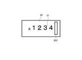
<変形例2>
図6は、変形例2に係る第一表示部30Bとライセンスプレート50を示す、車両1を後方から見た図である。図6に示すように、本変形例の車両用表示システム20において、車両1を後方から見て、第一表示部30Bは、ライセンスプレート50の内部であって、ライセンスプレート50の文字列51より下方に設けられている。第一表示部30Bがライセンスプレート50の内部に設けられているため、第一表示部30Bが設けられている位置がより後方の車両1のドライバーにとって視認しやすい位置となっている。
例えば、ライセンスプレート50に孔部を設け、この孔部から第一表示部30Bが外部に露出するように、第一表示部30Bを配置することができる。
なお、図示の例とは異なり、第一表示部は、ライセンスプレート50の内部であって、ライセンスプレート50の文字列51より上方に設けてもよい。<
FIG. 6 is a view of the
For example, a hole may be provided in the
Note that, unlike the illustrated example, the first display unit may be provided inside the
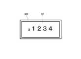
<変形例3>
図7は、本発明の変形例3に係る第一表示部30Cとライセンスプレート50を示す、車両1を後方から見た図である。図7に示すように、本変形例の車両用表示システム20において、車両1を後方から見て、第一表示部30Cは、ライセンスプレート50の内部であって、ライセンスプレート50の文字列51より右方に設けられている。第一表示部30Cが設けられている位置がより後方の車両1のドライバーにとって視認しやすい位置となっている。例えば、ライセンスプレート50に孔部を設け、この孔部から第一表示部30Cが外部に露出するように、第一表示部30Cを配置することができる。
なお、図示の例とは異なり、第一表示部は、ライセンスプレート50の内部であって、ライセンスプレート50の文字列51より左方に設けてもよい。<
FIG. 7 is a rear view of the
Note that, unlike the illustrated example, the first display unit may be provided inside the
<変形例4>
図8は、本発明の変形例4に係る第一表示部30Dとライセンスプレート50を示す、車両1を後方から見た図である。ライセンスプレート50はボルトなどの締結具52を介して車体へ取り付けられている。図8に示すように、本変形例の車両用表示システム20において、車両1を後方から見て、第一表示部30Dは、ライセンスプレート50の内部であって、ライセンスプレート50を車体へ取り付ける締結具52と重なる位置に設けられている。締結具52を第一表示部30Dで覆うことにより、ライセンスプレート50周囲をシンプルな意匠に構成することができ、車両1の意匠性を高めることができる。<Modification example 4>
FIG. 8 is a view of the
また、上述した実施形態や変形例1~3においては第一表示部を矩形状の部材として説明したが、本変形例4のように円状の部材として構成してもよい。また、第一表示部は、楕円や多角形状、あるいは円柱、円錐、多角柱、多角錐形状に構成してもよい。 Further, although the first display unit has been described as a rectangular member in the above-described embodiments and
<変形例5>
図9は、本発明の変形例5に係る第一表示部30Eとライセンスプレート50を示す、車両1を後方から見た図である。図9に示すように、本変形例の車両用表示システム20において、車両1を後方から見て、第一表示部30Eは、ライセンスプレート50を縁取るように設けられている。
例えば、複数の第一光源をライセンスプレート50の外縁に沿って配列することにより、ライセンスプレート50を縁取る第一表示部30Eを構成することができる。あるいは、ライセンスプレート50の外周に沿って配置したライトガイドを単一または複数個の光源から出射された光で発光させることにより、ライセンスプレート50を縁取る第一表示部30Eを構成することができる。<
FIG. 9 is a view of the
For example, by arranging a plurality of first light sources along the outer edge of the
以上、本発明の実施形態について説明をしたが、本発明の技術的範囲が本実施形態の説明によって限定的に解釈されるべきではないのは言うまでもない。本実施形態は単なる一例であって、特許請求の範囲に記載された発明の範囲内において、様々な実施形態の変更が可能であることが当業者によって理解されるところである。本発明の技術的範囲は特許請求の範囲に記載された発明の範囲及びその均等の範囲に基づいて定められるべきである。 Although the embodiments of the present invention have been described above, it goes without saying that the technical scope of the present invention should not be construed as being limited by the description of the present embodiments. It is understood by those skilled in the art that the present embodiment is merely an example, and various embodiments can be modified within the scope of the invention described in the claims. The technical scope of the present invention should be determined based on the scope of the invention described in the claims and the scope thereof.
第一表示部および第二表示部は、上述したようにレンズ、液晶素子、反射板、光源自体、ライトガイドなどで構成することができる。 As described above, the first display unit and the second display unit can be composed of a lens, a liquid crystal element, a reflector, a light source itself, a light guide, and the like.
なお、上述した変形例1~5においては、第二表示部を持たない車両用表示システムを例示したが、変形例1~5の構成に第二表示部を追加してもよい。第二表示部は、ライセンスプレートの中心に対して第一表示部と対象となるように配置すると好ましい。 Although the vehicle display system having no second display unit is illustrated in the above-mentioned
また、上述の説明においては、表示制御部4を含む車両用表示システム20が車両システム2とは別の独立したシステムとして構成される例を想定しているが、この構成に限定されない。例えば、車両用表示システムは、車両制御部3を含むシステムとして構成されていてもよい。あるいは、車両用表示システムは、車両システム2に接続されている例えばカメラ、センサ、レーダ等を含むシステムとして構成されていてもよい。また、表示制御部4は、車両制御部3を構成するECUの一部として構成してもよい。この場合、表示制御部4はランプユニット100ではなく、車両1に搭載される。 Further, in the above description, an example is assumed in which the
本実施形態では、車両の運転モードは、完全自動運転モードと、高度運転支援モードと、運転支援モードと、完全手動運転モードとを含むものとして説明したが、車両の運転モードは、これら4つのモードに限定されるべきではない。 In the present embodiment, the driving mode of the vehicle has been described as including a fully automatic driving mode, an advanced driving support mode, a driving support mode, and a fully manual driving mode. However, there are four driving modes of the vehicle. It should not be limited to modes.
さらに、車両の運転モードの区分や表示形態は、各国における自動運転に係る法令又は規則に沿って適宜変更されてもよい。同様に、本実施形態の説明で記載された「完全自動運転モード」、「高度運転支援モード」、「運転支援モード」のそれぞれの定義はあくまでも一例であって、各国における自動運転に係る法令又は規則に沿って、これらの定義は適宜変更されてもよい。 Further, the classification and display form of the driving mode of the vehicle may be appropriately changed in accordance with the laws and regulations relating to automatic driving in each country. Similarly, the definitions of "fully automatic driving mode", "advanced driving support mode", and "driving support mode" described in the description of this embodiment are merely examples, and the laws and regulations related to automatic driving in each country or In line with the rules, these definitions may be changed accordingly.
1:車両
2:車両システム
3:車両制御部
4:表示制御部
20:車両用表示システム
30:第一表示部
31:第一光源
40:第二表示部
50:ライセンスプレート
51:文字列
1: Vehicle 2: Vehicle system 3: Vehicle control unit 4: Display control unit 20: Vehicle display system 30: First display unit 31: First light source 40: Second display unit 50: License plate 51: Character string
Claims (6)
Translated fromJapanese前記車両を後方から見て、ライセンスプレートの外部であって、前記ライセンスプレートの左方と右方の一方に設けられた第一表示部と、
前記車両を後方から見て、前記ライセンスプレートの外部であって、前記ライセンスプレートの左方と右方の他方に設けられた第二表示部と、
自動運転モードのレベルに応じて異なる態様で前記第一表示部を点灯させて、前記自動運転モードのレベルが変化しなくても異なる態様で前記第二表示部を点灯させるように構成された表示制御部とを有する、車両用表示システム。A vehicle display system used with a vehicle control unit that can control a vehicle in automatic driving mode.
When the vehicle is viewed from the rear,the first display unit, which is outside the license plate and is provided on either the left side or the right side of the license plate ,
When the vehicle is viewed from the rear, a second display unit outside the license plate and provided on the left and right sides of the license plate, and
The first display unit is lit in a different manner according to the level of the automatic operation mode, and the second display unit is lit in a different manner even if the level of the automatic operation mode does not change . A vehicle display system having a display control unit.
前記光源は、前記車両を後方から見て、前記表示部と重なる位置に設けられている、請求項1に記載の車両用表示システム。It has a light source that emits light from the display unit, and has a light source.
The vehicle display system according to claim 1, wherein the light source is provided at a position overlapping the display unit when the vehicle is viewed from the rear.
前記光源は、前記車両を後方から見て、前記表示部と重ならない位置に設けられている、請求項1に記載の車両用表示システム。It has a light source that emits light from the display unit, and has a light source.
The vehicle display system according to claim 1, wherein the light source is provided at a position that does not overlap with the display unit when the vehicle is viewed from the rear.
Priority Applications (5)
| Application Number | Priority Date | Filing Date | Title |
|---|---|---|---|
| JP2017254186AJP7025926B2 (en) | 2017-12-28 | 2017-12-28 | Vehicle display system |
| US16/214,809US10994658B2 (en) | 2017-12-28 | 2018-12-10 | Vehicle display system |
| CN201811516225.7ACN109969086B (en) | 2017-12-28 | 2018-12-12 | Display system for vehicle |
| DE102018251753.3ADE102018251753A1 (en) | 2017-12-28 | 2018-12-27 | Vehicle display system |
| FR1874298AFR3076886A1 (en) | 2017-12-28 | 2018-12-28 | VEHICLE DISPLAY SYSTEM |
Applications Claiming Priority (1)
| Application Number | Priority Date | Filing Date | Title |
|---|---|---|---|
| JP2017254186AJP7025926B2 (en) | 2017-12-28 | 2017-12-28 | Vehicle display system |
Publications (2)
| Publication Number | Publication Date |
|---|---|
| JP2019119289A JP2019119289A (en) | 2019-07-22 |
| JP7025926B2true JP7025926B2 (en) | 2022-02-25 |
Family
ID=66817115
Family Applications (1)
| Application Number | Title | Priority Date | Filing Date |
|---|---|---|---|
| JP2017254186AActiveJP7025926B2 (en) | 2017-12-28 | 2017-12-28 | Vehicle display system |
Country Status (5)
| Country | Link |
|---|---|
| US (1) | US10994658B2 (en) |
| JP (1) | JP7025926B2 (en) |
| CN (1) | CN109969086B (en) |
| DE (1) | DE102018251753A1 (en) |
| FR (1) | FR3076886A1 (en) |
Families Citing this family (32)
| Publication number | Priority date | Publication date | Assignee | Title |
|---|---|---|---|---|
| JP7275913B2 (en)* | 2019-06-27 | 2023-05-18 | 株式会社三洋物産 | game machine |
| JP7275908B2 (en)* | 2019-06-27 | 2023-05-18 | 株式会社三洋物産 | game machine |
| JP7275909B2 (en)* | 2019-06-27 | 2023-05-18 | 株式会社三洋物産 | game machine |
| JP7275912B2 (en)* | 2019-06-27 | 2023-05-18 | 株式会社三洋物産 | game machine |
| JP7275916B2 (en)* | 2019-06-27 | 2023-05-18 | 株式会社三洋物産 | game machine |
| JP7275911B2 (en)* | 2019-06-27 | 2023-05-18 | 株式会社三洋物産 | game machine |
| JP7275910B2 (en)* | 2019-06-27 | 2023-05-18 | 株式会社三洋物産 | game machine |
| JP7275914B2 (en)* | 2019-06-27 | 2023-05-18 | 株式会社三洋物産 | game machine |
| JP7302376B2 (en)* | 2019-08-22 | 2023-07-04 | 株式会社三洋物産 | game machine |
| JP7302377B2 (en)* | 2019-08-22 | 2023-07-04 | 株式会社三洋物産 | game machine |
| JP7302374B2 (en)* | 2019-08-22 | 2023-07-04 | 株式会社三洋物産 | game machine |
| JP7302378B2 (en)* | 2019-08-22 | 2023-07-04 | 株式会社三洋物産 | game machine |
| JP7302375B2 (en)* | 2019-08-22 | 2023-07-04 | 株式会社三洋物産 | game machine |
| JP7302373B2 (en)* | 2019-08-22 | 2023-07-04 | 株式会社三洋物産 | game machine |
| JP7302372B2 (en)* | 2019-08-22 | 2023-07-04 | 株式会社三洋物産 | game machine |
| JP7307330B2 (en)* | 2019-08-22 | 2023-07-12 | 株式会社三洋物産 | game machine |
| JP7302379B2 (en)* | 2019-08-23 | 2023-07-04 | 株式会社三洋物産 | game machine |
| JP7307331B2 (en)* | 2019-08-23 | 2023-07-12 | 株式会社三洋物産 | game machine |
| JP7342588B2 (en)* | 2019-10-03 | 2023-09-12 | 株式会社三洋物産 | gaming machine |
| JP7342586B2 (en)* | 2019-10-03 | 2023-09-12 | 株式会社三洋物産 | gaming machine |
| JP7342585B2 (en)* | 2019-10-03 | 2023-09-12 | 株式会社三洋物産 | gaming machine |
| JP7342589B2 (en)* | 2019-10-03 | 2023-09-12 | 株式会社三洋物産 | gaming machine |
| JP7342587B2 (en)* | 2019-10-03 | 2023-09-12 | 株式会社三洋物産 | gaming machine |
| JP7342584B2 (en)* | 2019-10-03 | 2023-09-12 | 株式会社三洋物産 | gaming machine |
| JP7437982B2 (en)* | 2020-03-10 | 2024-02-26 | 本田技研工業株式会社 | Mobile object control device, mobile object control method, and program |
| JP7422063B2 (en)* | 2020-12-23 | 2024-01-25 | 本田技研工業株式会社 | mobile object |
| WO2022230779A1 (en)* | 2021-04-27 | 2022-11-03 | 株式会社デンソー | Vehicular notification control device and vehicular notification control method |
| JP7480801B2 (en)* | 2021-04-27 | 2024-05-10 | 株式会社デンソー | Vehicle notification control device and vehicle notification control method |
| JP7638170B2 (en) | 2021-06-23 | 2025-03-03 | スタンレー電気株式会社 | Vehicle lighting fixtures |
| CN114851956B (en)* | 2022-05-24 | 2024-09-17 | 中国第一汽车股份有限公司 | Method, device, storage medium and processor for vehicle information interaction |
| KR102813575B1 (en)* | 2023-08-28 | 2025-05-30 | 주식회사 제이에스브이 | Cover type assistant unit of vehicle license plate |
| KR102813576B1 (en)* | 2023-08-28 | 2025-05-30 | 주식회사 제이에스브이 | Display type vehicle license plate |
Citations (3)
| Publication number | Priority date | Publication date | Assignee | Title |
|---|---|---|---|---|
| JP2003285686A (en) | 2002-03-28 | 2003-10-07 | Kenji Ishiguro | Direction indicator for motorcycle |
| WO2017073632A1 (en) | 2015-10-27 | 2017-05-04 | 株式会社小糸製作所 | Vehicular illumination device, vehicle system, and vehicle |
| JP2017178078A (en) | 2016-03-30 | 2017-10-05 | トヨタ自動車株式会社 | Hybrid car |
Family Cites Families (21)
| Publication number | Priority date | Publication date | Assignee | Title |
|---|---|---|---|---|
| JPS6015309B2 (en) | 1982-06-07 | 1985-04-18 | ユニヴア−サル・フツヅ・コ−ポレ−シヨン | Production method of chromium yeast |
| JPH0769130A (en)* | 1993-09-02 | 1995-03-14 | Morozumi Rikio | Car rear light |
| JPH09277887A (en) | 1996-04-16 | 1997-10-28 | Honda Motor Co Ltd | Automatic tracking system |
| JPH10181469A (en)* | 1996-10-21 | 1998-07-07 | Tamashima Press Kogyo Kk | Vehicle provided with speed indicating means |
| US9663028B2 (en)* | 2010-05-27 | 2017-05-30 | Frederick Hayle Parkes | Method and system for rendering content on the exterior of a vehicle |
| US9020657B2 (en)* | 2011-05-09 | 2015-04-28 | Joseph D. Uhler | Method for automated VIN acquisition and close proximity VIN verification |
| WO2013033686A2 (en)* | 2011-09-01 | 2013-03-07 | Alexander Flavio Panelli | Method and apparatus for social telematics |
| JP6015309B2 (en) | 2012-09-28 | 2016-10-26 | 日産自動車株式会社 | Display device in steering wheel |
| WO2014055405A1 (en)* | 2012-10-01 | 2014-04-10 | Cunningham Thomas W | Electronic vehicle information system, electronic license plates and other related devices and methods |
| US9483777B2 (en)* | 2013-06-24 | 2016-11-01 | Ananda Sarangi | Content display on moving vehicles |
| US20150194082A1 (en)* | 2014-01-03 | 2015-07-09 | John Arthur MCEWAN | Systems, devices, and methods for displaying accessories and information from a vehicle |
| DE102014225804A1 (en)* | 2014-12-15 | 2016-06-16 | Bayerische Motoren Werke Aktiengesellschaft | Assistance in driving a vehicle |
| JP6642972B2 (en)* | 2015-03-26 | 2020-02-12 | 修一 田山 | Vehicle image display system and method |
| US10493936B1 (en)* | 2016-01-22 | 2019-12-03 | State Farm Mutual Automobile Insurance Company | Detecting and responding to autonomous vehicle collisions |
| CN206394528U (en)* | 2016-08-22 | 2017-08-11 | 上海小糸车灯有限公司 | A kind of intelligent automotive light of circular autonomous driving vehicle vehicle body |
| CN106515574B (en)* | 2016-10-25 | 2019-03-12 | 北京汽车集团有限公司 | The identity device and method of automatic driving vehicle |
| CN106740848B (en)* | 2016-12-24 | 2019-03-22 | 北汽福田汽车股份有限公司 | Assist the method, apparatus driven and vehicle |
| US20180191510A1 (en)* | 2017-01-05 | 2018-07-05 | Revivermx, Inc. | Secure Communication System And Software Architecture For A Digital License Plate |
| JP6547155B2 (en)* | 2017-06-02 | 2019-07-24 | 本田技研工業株式会社 | Vehicle control system, vehicle control method, and program |
| JP6460425B2 (en)* | 2017-06-02 | 2019-01-30 | 本田技研工業株式会社 | Vehicle control system, vehicle control method, and program |
| JP6917827B2 (en)* | 2017-08-14 | 2021-08-11 | 本田技研工業株式会社 | Vehicle control devices, vehicles, vehicle control methods and programs |
- 2017
- 2017-12-28JPJP2017254186Apatent/JP7025926B2/enactiveActive
- 2018
- 2018-12-10USUS16/214,809patent/US10994658B2/ennot_activeExpired - Fee Related
- 2018-12-12CNCN201811516225.7Apatent/CN109969086B/enactiveActive
- 2018-12-27DEDE102018251753.3Apatent/DE102018251753A1/ennot_activeWithdrawn
- 2018-12-28FRFR1874298Apatent/FR3076886A1/ennot_activeWithdrawn
Patent Citations (3)
| Publication number | Priority date | Publication date | Assignee | Title |
|---|---|---|---|---|
| JP2003285686A (en) | 2002-03-28 | 2003-10-07 | Kenji Ishiguro | Direction indicator for motorcycle |
| WO2017073632A1 (en) | 2015-10-27 | 2017-05-04 | 株式会社小糸製作所 | Vehicular illumination device, vehicle system, and vehicle |
| JP2017178078A (en) | 2016-03-30 | 2017-10-05 | トヨタ自動車株式会社 | Hybrid car |
Also Published As
| Publication number | Publication date |
|---|---|
| FR3076886A1 (en) | 2019-07-19 |
| US10994658B2 (en) | 2021-05-04 |
| JP2019119289A (en) | 2019-07-22 |
| CN109969086A (en) | 2019-07-05 |
| DE102018251753A1 (en) | 2019-07-04 |
| CN109969086B (en) | 2022-08-16 |
| US20190202357A1 (en) | 2019-07-04 |
Similar Documents
| Publication | Publication Date | Title |
|---|---|---|
| JP7025926B2 (en) | Vehicle display system | |
| JP7045993B2 (en) | Vehicle lighting systems, vehicle systems and vehicles | |
| JP7522892B2 (en) | vehicle | |
| US11351912B2 (en) | Vehicle headlamp system and vehicle lamp system | |
| US12296676B2 (en) | Vehicle communication system, vehicle module, front composite module, and vehicle lamp | |
| JP6774954B2 (en) | Vehicle parts and vehicles | |
| JP6914843B2 (en) | Vehicle lighting equipment, vehicle systems and vehicles | |
| JP7389789B2 (en) | Vehicle emblem system, vehicle emblem unit, vehicle emblem mounting unit | |
| JP6970612B2 (en) | Vehicle lighting system and vehicle | |
| US10730427B2 (en) | Lighting device | |
| CN110126719B (en) | Lighting system for vehicle and vehicle | |
| JP2020093737A (en) | Infrared camera system and vehicle | |
| JP7067540B2 (en) | Vehicle display device | |
| WO2017110935A1 (en) | Vehicle illumination device, vehicle, and illumination control system | |
| JP6980553B2 (en) | Vehicle lighting system and vehicle | |
| WO2022230779A1 (en) | Vehicular notification control device and vehicular notification control method | |
| JP2023017395A (en) | Vehicle drawing device |
Legal Events
| Date | Code | Title | Description |
|---|---|---|---|
| A621 | Written request for application examination | Free format text:JAPANESE INTERMEDIATE CODE: A621 Effective date:20201109 | |
| A977 | Report on retrieval | Free format text:JAPANESE INTERMEDIATE CODE: A971007 Effective date:20210910 | |
| A131 | Notification of reasons for refusal | Free format text:JAPANESE INTERMEDIATE CODE: A131 Effective date:20210921 | |
| A521 | Request for written amendment filed | Free format text:JAPANESE INTERMEDIATE CODE: A523 Effective date:20211112 | |
| TRDD | Decision of grant or rejection written | ||
| A01 | Written decision to grant a patent or to grant a registration (utility model) | Free format text:JAPANESE INTERMEDIATE CODE: A01 Effective date:20220125 | |
| A61 | First payment of annual fees (during grant procedure) | Free format text:JAPANESE INTERMEDIATE CODE: A61 Effective date:20220214 | |
| R150 | Certificate of patent or registration of utility model | Ref document number:7025926 Country of ref document:JP Free format text:JAPANESE INTERMEDIATE CODE: R150 |