JP7023432B2 - Data processing equipment, data processing method and data processing program - Google Patents
Data processing equipment, data processing method and data processing programDownload PDFInfo
- Publication number
- JP7023432B2 JP7023432B2JP2021561052AJP2021561052AJP7023432B2JP 7023432 B2JP7023432 B2JP 7023432B2JP 2021561052 AJP2021561052 AJP 2021561052AJP 2021561052 AJP2021561052 AJP 2021561052AJP 7023432 B2JP7023432 B2JP 7023432B2
- Authority
- JP
- Japan
- Prior art keywords
- data
- related data
- devices
- unit
- data processing
- Prior art date
- Legal status (The legal status is an assumption and is not a legal conclusion. Google has not performed a legal analysis and makes no representation as to the accuracy of the status listed.)
- Active
Links
Images


Classifications
- G—PHYSICS
- G05—CONTROLLING; REGULATING
- G05B—CONTROL OR REGULATING SYSTEMS IN GENERAL; FUNCTIONAL ELEMENTS OF SUCH SYSTEMS; MONITORING OR TESTING ARRANGEMENTS FOR SUCH SYSTEMS OR ELEMENTS
- G05B19/00—Programme-control systems
- G05B19/02—Programme-control systems electric
- G05B19/418—Total factory control, i.e. centrally controlling a plurality of machines, e.g. direct or distributed numerical control [DNC], flexible manufacturing systems [FMS], integrated manufacturing systems [IMS] or computer integrated manufacturing [CIM]
- G05B19/41885—Total factory control, i.e. centrally controlling a plurality of machines, e.g. direct or distributed numerical control [DNC], flexible manufacturing systems [FMS], integrated manufacturing systems [IMS] or computer integrated manufacturing [CIM] characterised by modeling, simulation of the manufacturing system
- G—PHYSICS
- G06—COMPUTING OR CALCULATING; COUNTING
- G06Q—INFORMATION AND COMMUNICATION TECHNOLOGY [ICT] SPECIALLY ADAPTED FOR ADMINISTRATIVE, COMMERCIAL, FINANCIAL, MANAGERIAL OR SUPERVISORY PURPOSES; SYSTEMS OR METHODS SPECIALLY ADAPTED FOR ADMINISTRATIVE, COMMERCIAL, FINANCIAL, MANAGERIAL OR SUPERVISORY PURPOSES, NOT OTHERWISE PROVIDED FOR
- G06Q10/00—Administration; Management
- G06Q10/06—Resources, workflows, human or project management; Enterprise or organisation planning; Enterprise or organisation modelling
- G06Q10/063—Operations research, analysis or management
- G—PHYSICS
- G06—COMPUTING OR CALCULATING; COUNTING
- G06Q—INFORMATION AND COMMUNICATION TECHNOLOGY [ICT] SPECIALLY ADAPTED FOR ADMINISTRATIVE, COMMERCIAL, FINANCIAL, MANAGERIAL OR SUPERVISORY PURPOSES; SYSTEMS OR METHODS SPECIALLY ADAPTED FOR ADMINISTRATIVE, COMMERCIAL, FINANCIAL, MANAGERIAL OR SUPERVISORY PURPOSES, NOT OTHERWISE PROVIDED FOR
- G06Q50/00—Information and communication technology [ICT] specially adapted for implementation of business processes of specific business sectors, e.g. utilities or tourism
- G06Q50/04—Manufacturing
- G—PHYSICS
- G05—CONTROLLING; REGULATING
- G05B—CONTROL OR REGULATING SYSTEMS IN GENERAL; FUNCTIONAL ELEMENTS OF SUCH SYSTEMS; MONITORING OR TESTING ARRANGEMENTS FOR SUCH SYSTEMS OR ELEMENTS
- G05B2219/00—Program-control systems
- G05B2219/30—Nc systems
- G05B2219/32—Operator till task planning
- G05B2219/32385—What is simulated, manufacturing process and compare results with real process
Landscapes
- Engineering & Computer Science (AREA)
- Business, Economics & Management (AREA)
- Human Resources & Organizations (AREA)
- Economics (AREA)
- Physics & Mathematics (AREA)
- General Physics & Mathematics (AREA)
- Strategic Management (AREA)
- Manufacturing & Machinery (AREA)
- Quality & Reliability (AREA)
- Entrepreneurship & Innovation (AREA)
- Theoretical Computer Science (AREA)
- General Business, Economics & Management (AREA)
- Marketing (AREA)
- Tourism & Hospitality (AREA)
- Automation & Control Theory (AREA)
- Primary Health Care (AREA)
- General Health & Medical Sciences (AREA)
- Health & Medical Sciences (AREA)
- Development Economics (AREA)
- Educational Administration (AREA)
- General Engineering & Computer Science (AREA)
- Game Theory and Decision Science (AREA)
- Operations Research (AREA)
- User Interface Of Digital Computer (AREA)
- Management, Administration, Business Operations System, And Electronic Commerce (AREA)
- Information Retrieval, Db Structures And Fs Structures Therefor (AREA)
Description
Translated fromJapanese本開示は、機器を管理する技術に関する。 The present disclosure relates to technology for managing equipment.
従来より、工場内の機器等の管理方法として、機器の物理的な配置、機器間の電気的な接続関係などの情報を管理する方法が取られている。
例えば、特許文献1では、工場内の機器がデータモデルとして管理され、機器間の関係が複数の定義方式で示される複数の機器関係データが表示される。特許文献1では、例えば、機器の物理配置が示される機器関係データ、機器間の電気的接続関係が示される機器関係データが表示される。Conventionally, as a method of managing equipment in a factory, a method of managing information such as physical arrangement of equipment and electrical connection relationship between equipment has been adopted.
For example, in
特許文献1の技術では、機器間の関係を複数の定義方式の複数の機器関係データで表示することができる。複数の機器関係データには、同一の機器が重複して含まれるが、特許文献1の技術では、ユーザは、同一の機器を同一の機器として認識することができないという課題がある。 In the technique of
本開示は、上記のような課題を解決することを主な目的の一つとしている。より具体的には、本開示は、複数の機器関係データに重複して含まれる同一の機器を認識できるようにすることを主な目的とする。 One of the main purposes of this disclosure is to solve the above problems. More specifically, the main object of the present disclosure is to enable recognition of the same device included in a plurality of device-related data in duplicate.
本開示に係るデータ処理装置は、
各々に複数の機器が記述され、前記複数の機器の間の関係が相互に異なる定義方式で定義される複数の機器関係データを表示する表示部と、
前記複数の機器のうちのいずれかの機器を対象機器として指定する機器指定部と、
機器関係データごとに、前記対象機器の記述を抽出する機器抽出部とを有し、
前記表示部は、
前記複数の機器関係データにおいて前記対象機器の記述を相互に対応付ける。The data processing device according to the present disclosure is
A display unit that displays a plurality of device-related data in which a plurality of devices are described in each and the relationships between the plurality of devices are defined by different definition methods.
A device designation unit that designates one of the plurality of devices as a target device, and
It has a device extraction unit that extracts the description of the target device for each device-related data.
The display unit is
The description of the target device is associated with each other in the plurality of device-related data.
本開示によれば、複数の機器関係データに重複して含まれる同一の機器を認識することができる。 According to the present disclosure, it is possible to recognize the same device included in a plurality of device-related data in duplicate.
以下、実施の形態を図を用いて説明する。以下の実施の形態の説明及び図面において、同一の符号を付したものは、同一の部分又は相当する部分を示す。 Hereinafter, embodiments will be described with reference to the drawings. In the following description and drawings of the embodiments, those having the same reference numerals indicate the same parts or corresponding parts.
実施の形態1.
***構成の説明***
図1は、本実施の形態に係るデータ処理装置100の機能構成例を示す。
データ処理装置100は、コンピュータである。また、データ処理装置100の動作手順は、データ処理方法に相当する。また、データ処理装置100の動作を実現するプログラムは、データ処理プログラムに相当する。
*** Explanation of configuration ***
FIG. 1 shows an example of a functional configuration of the
The
データ処理装置100は、複数の機器300の間の関係が示される機器関係データを生成し、生成した機器関係データを表示する。機器300は、例えば、工場に配置される機器である。
また、データ処理装置100は、外部ツール200を介して複数の機器300の各々にアクセスすることができる。The
Further, the
データモデル生成部101は、データモデルを生成する。データモデルの詳細は後述する。 The data
データ変換部102は、データモデル生成部101により生成されたデータモデルを別の形式のデータに変換する。本実施の形態では、データ変換部102は、データモデルをXML形式のデータに変換する。なお、データ変換部102により変換された後のデータを変換データという。 The
変換データ記憶部107は、変換データを記憶する。 The conversion
機器指定部103は、データ処理装置100のユーザの指示に従い、複数の機器300うちのいずれかの機器300を対象機器として指定する。
機器指定部103により行われる処理は、機器指定処理に相当する。The
The process performed by the
機器関係データ生成部104は、変換データ記憶部107から変換データを取得し、変換データを用いて、複数の機器関係データを生成する。複数の機器関係データの各々では、複数の機器300が記述され、複数の機器300の間の関係が相互に異なる定義方式で定義される。本実施の形態では、機器関係データ生成部104は、一例として、機器の物理的配置が示される機器関係データ、機器間の電気的接続関係が示される機器関係データ、機器間のネットワーク接続関係が示される機器関係データを生成するものとする。以下、機器の物理的配置が示される機器関係データを物理配置データという。また、機器間の電気的接続関係が示される機器関係データを電気的接続関係データという。また、機器間のネットワーク接続関係が示される機器関係データをネットワーク接続関係データという。
そして、機器関係データ生成部104は、生成した物理配置データ、電気的接続関係データ及びネットワーク接続関係データを表示部106に出力する。
また、機器指定部103により対象機器が指定された場合に、機器関係データ生成部104は、機器関係データごとに対象機器の記述を抽出する。つまり、機器関係データ生成部104は、物理配置データ、電気的接続関係データ及びネットワーク接続関係の各々において、対象機器の記述位置を特定する。そして、機器関係データ生成部104は、特定した、物理配置データ、電気的接続関係データ及びネットワーク接続関係の各々における対象機器の記述位置を表示部106に通知する。
また、機器関係データ生成部104は、後述する外部ツール連携部105により取得された機器300の状態値を示す状態値表示データを生成し、生成した状態値表示データを表示部106に出力する。
機器関係データ生成部104は、機器抽出部に相当する。また、機器関係データ生成部104により行われる処理は、機器抽出処理に相当する。The device-related
Then, the device-related
Further, when the target device is designated by the
Further, the device-related
The device-related
外部ツール連携部105は、外部ツール200を介して、各機器300の状態を表す状態値を取得する。
状態値は、例えば、機器300の電流値、電圧値、電力値等である。
外部ツール連携部105は、外部ツール200を介して取得した状態値を機器関係データ生成部104に出力する。
また、外部ツール連携部105は、機器関係データを外部ツール200に出力することができる。The external
The state value is, for example, a current value, a voltage value, a power value, or the like of the
The external
Further, the external
表示部106は、機器関係データ生成部104から出力された複数の機器関係データをディスプレイ装置に表示する。
また、表示部106は、機器関係データ生成部104から対象機器の記述位置が通知された場合は、複数の機器関係データにおいて対象機器の記述を相互に対応付ける。
また、機器関係データ生成部104から状態値表示データが出力された場合は、状態値表示データをディスプレイ装置に表示する。
表示部106により行われる処理は表示処理に相当する。The
Further, when the device-related
Further, when the state value display data is output from the device-related
The processing performed by the
図2は、本実施の形態に係るデータ処理装置100のハードウェア構成例を示す。 FIG. 2 shows a hardware configuration example of the
データ処理装置100は、ハードウェアとして、プロセッサ901、主記憶装置902、補助記憶装置903及び通信装置904、入出力装置905を備える。
補助記憶装置903には、データモデル生成部101、データ変換部102、機器指定部103、機器関係データ生成部104、外部ツール連携部105及び表示部106の機能を実現するプログラムが記憶されている。
これらプログラムは、補助記憶装置903から主記憶装置902にロードされる。そして、プロセッサ901がこれらプログラムを実行して、データモデル生成部101、データ変換部102、機器指定部103、機器関係データ生成部104、外部ツール連携部105及び表示部106の動作を行う。
図3では、プロセッサ901がデータモデル生成部101、データ変換部102、機器指定部103、機器関係データ生成部104、外部ツール連携部105及び表示部106の機能を実現するプログラムを実行している状態を模式的に表している。
通信装置904は、外部ツール200と通信を行うために用いられる。
入出力装置905は、キーボード、マウス、ディスプレイ装置等である。The
The
These programs are loaded from the
In FIG. 3, the
The
The input /
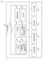
図3は、機器関係データの例を示す。
前述のように、本実施の形態では、機器関係データとして、物理的配置データ301、電気的接続関係データ302及びネットワーク接続関係データ303が生成される。FIG. 3 shows an example of device-related data.
As described above, in the present embodiment, the physical arrangement data 301, the electrical connection-related
物理的配置データ301では、工場内の物理的配置が示される。物理的配置データ301では、階層構造にて工場内の物理的配置が示される。
物理的配置データ301に示される要素のうち、トランス1、トランス2、MDU-B、シーケンサ、モータ、MELIPC、EcoServerが機器である。The physical arrangement data 301 indicates the physical arrangement in the factory. In the physical arrangement data 301, the physical arrangement in the factory is shown in a hierarchical structure.
Among the elements shown in the physical arrangement data 301, the
電気的接続関係データ302では、工場内の電気的接続関係が示される。ネットワーク接続関係データ303では、階層構造にて工場内の電気的接続関係が示される。
電気的接続関係データ302に示される要素のうち、トランス1、トランス2、ACB1、ACB2、VCB1、VCB2、MDU-A、MDU-B、シーケンサ、モータ、MELIPC、EcoServerが機器である。The electrical
Among the elements shown in the electrical connection-related
ネットワーク接続関係データ303では、工場内のネットワーク接続関係が示される。ネットワーク接続関係データ303では、階層構造にて工場内のネットワーク接続関係が示される。
ネットワーク接続関係データ303に示される要素のうち、ファイアウォール、DMZ、ルータ、PC、MELIPC、シーケンサ、モータ、EcoServer、EcoMonitor、MDU-Bが機器である。The network
Among the elements shown in the network connection-related
図3の例では、符号305で示すように、物理的配置データ301、電気的接続関係データ302及びネットワーク接続関係データ303の各々でMDU-Bが強調表示されている。つまり、図3の例では、機器指定部103によりMDU-Bが対象機器として指定され、機器関係データ生成部104が物理的配置データ301、電気的接続関係データ302及びネットワーク接続関係データ303の各々におけるMDU-Bの記述位置を抽出した例を示す。
このように、本実施の形態に係るデータ処理装置100は、複数の機器関係データにおいて同一の機器(MDU-B)を同一の機器として表示することができる。
なお、図3の例では、対象機器を点線で囲むことにより強調表示を行っているが、強調表示の方法はどのような方法でもよい。例えば、対象機器の文字列を他の機器の文字列と違う色で表示する、対象機器の領域の背景を他の機器の領域の背景と違う色にする等が考えられる。
なお、図3の物理的配置データ301、電気的接続関係データ302及びネットワーク接続関係データ303では、ツリーの最上位のルートノードが1つの例を示しているが、ルートノードが複数存在してもよい。In the example of FIG. 3, MDU-B is highlighted in each of the physical arrangement data 301, the electrical connection-related
As described above, the
In the example of FIG. 3, the target device is highlighted by surrounding it with a dotted line, but any method may be used for highlighting. For example, it is conceivable to display the character string of the target device in a color different from the character string of the other device, or to make the background of the area of the target device different from the background of the area of the other device.
The physical arrangement data 301, the electrical connection-related
図4は、本実施の形態に係る状態値表示データの例を示す。
図4の例では、MDU-Bの状態値として、電流値、電圧値、電力値、力率値が示される。FIG. 4 shows an example of the state value display data according to the present embodiment.
In the example of FIG. 4, the current value, the voltage value, the power value, and the power factor value are shown as the state values of the MDU-B.
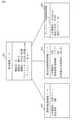
図5は、本実施の形態に係る機器情報入力画面501の例を示す。
図5は、図3のMDU-Bの機器情報を入力するための機器情報入力画面501を示す。FIG. 5 shows an example of the device
FIG. 5 shows a device
表示部106は、図5に示す機器情報入力画面501をディスプレイ装置に表示する。
ユーザは、機器情報入力画面に機器情報をマウス、キーボードを用いて入力する。
ユーザは、機器情報入力画面501に、基本情報、物理的配置情報、電気的接続情報及びネットワーク接続情報を入力する。
ユーザは、基本情報として、機器ID、機器名、機種名、プロファイル、バージョンを入力する。具体的には、ユーザは、機器IDをフィールド510に入力する。また、ユーザは機器名をフィールド511に入力する。また、ユーザは機種名をフィールド512に入力する。また、ユーザはプロファイルをフィールド513に入力する。また、ユーザはバージョンをフィールド514に入力する。
ユーザは、物理的配置情報として、上位機器名、設置場所を入力する。具体的には、ユーザは上位機器名をフィールド515に入力する。また、ユーザは設置場所をフィールド516に入力する。
ユーザは、電気的接続関係情報として、上位機器名、接続情報(接続線)、定格電圧/定格電流を入力する。具体的には、ユーザは上位機器名をフィールド517に入力する。また、ユーザは接続情報(接続線)をフィールド518に入力する。また、ユーザは定格電圧/定格電流をフィールド519に入力する。
ユーザは、ネットワーク接続情報として、上位機器名、通信方式名、通信アドレスを入力する。具体的には、ユーザは上位機器名をフィールド520に入力する。また、ユーザは通信方式名をフィールド521に入力する。また、ユーザは通信アドレスをフィールド522に入力する。The
The user inputs the device information on the device information input screen using the mouse and the keyboard.
The user inputs basic information, physical arrangement information, electrical connection information, and network connection information on the device
The user inputs the device ID, device name, model name, profile, and version as basic information. Specifically, the user inputs the device ID in the
The user inputs the name of the higher-level device and the installation location as the physical arrangement information. Specifically, the user inputs the name of the higher-level device in the
The user inputs the higher-level device name, connection information (connection line), and rated voltage / rated current as electrical connection-related information. Specifically, the user inputs the name of the higher-level device in the
The user inputs a higher-level device name, a communication method name, and a communication address as network connection information. Specifically, the user inputs the name of the higher-level device in the
図5では、MDU-Bの機器情報を入力するための機器情報入力画面501が示されるが、図3の各要素について、ユーザは機器情報入力画面501に必要な値を入力する。図3の最上位の要素、つまり、物理的配置データ301の工場、電気的接続関係データ302の高圧受電設備、ネットワーク接続関係データ303のインターネットには、上位機器が存在しないので、ユーザは、これらの要素については上位機器は入力しない。
ユーザは、機器情報入力画面501の入力が完了したら、保存ボタンを押下する。保存ボタンの押下により、機器情報入力画面501への入力値がデータモデル生成部101に入力される。
データモデル生成部101は、図5の機器情報入力画面501への入力値を用いて、要素ごとにデータモデルを生成する。FIG. 5 shows a device
The user presses the save button when the input of the device
The data
図6は、データモデル生成部101により生成されるデータモデルの例を示す。
より具体的には、図6は、図5の機器情報入力画面501から生成されたデータモデルの例を示す。つまり、図6は、MDU-Bのデータモデルを示す。FIG. 6 shows an example of a data model generated by the data
More specifically, FIG. 6 shows an example of a data model generated from the device
基本情報ノード601は、機器情報入力画面501の基本情報に対応するノードである。基本情報ノード601には、図5のフィールド511、フィールド512、フィールド513、フィールド514に入力された値が設定される。
物理的配置情報ノード602は、機器情報入力画面501の物理的配置情報に対応するノードである。物理的配置情報ノード602には、フィールド515、フィールド516に入力された値が設定される。
電気的接続情報ノード603は、機器情報入力画面501の電気的接続情報に対応するノードである。電気的接続情報ノード603には、フィールド517、フィールド518、フィールド519に入力された値が設定される。
ネットワーク接続情報ノード604は、機器情報入力画面501のネットワーク接続関係情報に対応するノードである。ネットワーク接続情報ノード604には、フィールド520、フィールド521、フィールド522に入力された値が設定される。The
The physical
The electrical
The network connection information node 604 is a node corresponding to the network connection-related information of the device
図6は、MDU-Bについてのデータモデルを示すが、データモデル生成部101は、図3の各要素について図6と同様のデータモデルを生成する。 FIG. 6 shows a data model for MDU-B, and the data
図7は、データ変換部102により生成される変換データ701の例を示す。図7は、データモデルをXML形式に変換して得られる変換データ701の例を示す。変換データ701には、図3に示される各要素が記述される。図7では、主にMDU-Bの記述が示される。 FIG. 7 shows an example of
基本情報ブロック711には、基本情報ノード601に記載された事項が記載される。
物理的配置情報ブロック712には、物理的配置情報ノード602に記載された事項が記載される。
電気的接続情報ブロック713には、電気的接続情報ノード603に記載された事項が記載される。
ネットワーク接続情報ブロック714には、ネットワーク接続情報ノード604に記載された事項が記載される。
MDU-B以外の機器についても同様の構成となっている。In the basic information block 711, the matters described in the
The physical placement information block 712 describes the items described in the physical
The electrical connection information block 713 describes the matters described in the electrical
The network connection information block 714 describes the items described in the network connection information node 604.
Devices other than MDU-B have the same configuration.
機器関係データ生成部104は、図7に示す変換データ701を解析して、物理的配置情報ブロック712から物理的配置データ301を生成する。また、機器関係データ生成部104は、電気的接続情報ブロック713から電気的接続関係データ302を生成する。また、機器関係データ生成部104は、ネットワーク接続情報ブロック714からネットワーク接続関係データ303を生成する。
より具体的には、機器関係データ生成部104は、最下位の階層の要素から順に、物理的配置情報ブロック712から直上の階層の要素(図7の例では、「生産ライン1」、「2階」)を抽出する動作を繰り返して、物理的配置データ301を生成する。機器関係データ生成部104は、電気的接続関係データ302についても、最下位の階層の要素から順に、電気的接続情報ブロック713から直上の階層の要素を抽出する動作を繰り返して、電気的接続関係データ302を生成する。また、機器関係データ生成部104は、ネットワーク接続関係データ303についても、最下位の階層の要素から順に、ネットワーク接続情報ブロック714から直上の階層の要素を抽出する動作を繰り返して、ネットワーク接続関係データ303を生成する。The device-related
More specifically, the device-related
***動作の説明***
図8及び図9を参照して、本実施の形態に係るデータ処理装置100の動作を説明する。
図8は、変換データの格納までの動作手順を示す。
図9は、機器関係データの生成及び表示、対象機器の強調表示、状態値表示データの生成及び表示についての動作手順を示す。*** Explanation of operation ***
The operation of the
FIG. 8 shows an operation procedure up to the storage of the converted data.
FIG. 9 shows an operation procedure for generating and displaying device-related data, highlighting the target device, and generating and displaying state value display data.
図8のステップS801において、データモデル生成部101が機器情報を取得する。
より具体的には、表示部106がディスプレイ装置に図5の機器情報入力画面501を表示する。そして、データモデル生成部101がキーボード、マウス等から、機器情報入力画面501の各フィールドの入力値を機器情報として取得する。In step S801 of FIG. 8, the data
More specifically, the
次に、ステップS802において、データモデル生成部101が、機器ごとに、機器情報入力画面501の入力値に基づき、図6のデータモデル(基本情報ノード601、物理的配置情報ノード602及び電気的接続情報ノード603)を生成する。
データモデル生成部101は、生成した機器ごとのデータモデルをデータ変換部102に出力する。Next, in step S802, the data
The data
次に、ステップS803において、データ変換部102がデータモデルを変換して、図7に例示する変換データを生成する。
より具体的には、データ変換部102は、機器ごとのデータモデルを統合し、また、統合したデータモデルを変換して図7に例示する変換データ701を得る。Next, in step S803, the
More specifically, the
そして、データ変換部102は、ステップS804において、変換データを変換データ記憶部107に格納する。 Then, in step S804, the
図9において、ユーザから機器関係データの表示が要求された場合(ステップS901でYES)に、ステップS902において、機器関係データ生成部104が、変換データ記憶部107から変換データを取得し、変換データを解析して機器関係データを生成する。つまり、機器関係データ生成部104は、図3の物理的配置データ301、電気的接続関係データ302及びネットワーク接続関係データ303を生成する。
前述したように、機器関係データ生成部104は、物理的配置情報ブロック712から物理的配置データ301を生成する。また、機器関係データ生成部104は、電気的接続情報ブロック713から電気的接続関係データ302を生成する。また、機器関係データ生成部104は、ネットワーク接続情報ブロック714からネットワーク接続関係データ303を生成する。In FIG. 9, when the user requests the display of the device-related data (YES in step S901), in step S902, the device-related
As described above, the device-related
そして、ステップS903において、表示部106が物理的配置データ301、電気的接続関係データ302及びネットワーク接続関係データ303をディスプレイ装置に表示する。この段階では、MDU-Bについての強調表示305は行われていない。 Then, in step S903, the
次に、ユーザからの指示をトリガーに機器指定部103が対象機器を指定した場合(ステップS904でYES)に、機器関係データ生成部104が各機器関係データから対象機器の記述を抽出する。
例えば、ユーザが物理的配置データ301に示されるMDU-Bをマウスクリックしたとする。これにより、機器指定部103はMDU-Bを対象機器に指定する。機器指定部103は、MDU-Bを対象機器として機器関係データ生成部104に通知する。
機器関係データ生成部104は、例えば、文字認識によりMDU-Bと同じ文字列を電気的接続関係データ302及びネットワーク接続関係データ303の各々で走査し、電気的接続関係データ302及びネットワーク接続関係データ303でのMDU-Bの記述位置を抽出する。
そして、機器関係データ生成部104は、抽出した電気的接続関係データ302及びネットワーク接続関係データ303でのMDU-Bの記述位置と、ユーザによりマウスクリックされた位置(物理的配置データ301でのMDU-Bの記述位置)を表示部106に通知するNext, when the
For example, suppose that the user clicks the MDU-B shown in the physical arrangement data 301 with the mouse. As a result, the
For example, the device-related
Then, the device-related
次に、表示部106が、ステップS906で、複数の機器関係データで対象機器の記述を相互に対応付けて表示する。つまり、表示部106は、物理的配置データ301、電気的接続関係データ302及びネットワーク接続関係データ303の各々で、機器関係データ生成部104により通知された記述位置を強調表示する。 Next, in step S906, the
次に、ユーザによりいずれかの機器について状態値の表示が要求された場合(ステップS907でYES)に、ステップS908において、外部ツール連携部105が外部ツール200を介して該当する機器300にアクセスし、機器300から状態値を取得する。
外部ツール連携部105は、取得した状態値を機器関係データ生成部104に通知する。Next, when the user requests the display of the status value for any of the devices (YES in step S907), in step S908, the external
The external
ステップS909において、機器関係データ生成部104は、外部ツール連携部105から通知された状態値を示す状態値表示データを生成し、表示部106が状態値表示データをディスプレイ装置に表示する。 In step S909, the device-related
***実施の形態の効果の説明***
以上のように、本実施の形態によれば、複数の機器関係データに重複して含まれる同一の機器を同一の機器として表示することができる。
これにより、ユーザは、複数の機器関係データに重複して含まれる同一の機器を同一の機器として認識することができる。また、同一の機器を認識できるため、ユーザは、工場における物理的配置、電気的接続関係及びネットワーク接続関係を正確に理解することができる。
また、本実施の形態によれば、機器の現在の状態値が表示されるため、ユーザは機器の現在の状態を把握することができる。*** Explanation of the effect of the embodiment ***
As described above, according to the present embodiment, the same device included in a plurality of device-related data in duplicate can be displayed as the same device.
As a result, the user can recognize the same device included in the plurality of device-related data in duplicate as the same device. In addition, since the same device can be recognized, the user can accurately understand the physical arrangement, electrical connection relationship, and network connection relationship in the factory.
Further, according to the present embodiment, since the current state value of the device is displayed, the user can grasp the current state of the device.
なお、以上では、機器関係データの例として、物理的配置データ301、電気的接続関係データ302及びネットワーク接続関係データ303を示したが、機器関係データは、これらに限らない。
また、以上では、機器関係データをデータ処理装置100のユーザに提示する例を主に説明したが、機器関係データをデータ処理装置100の外部に提示することも可能である。具体的には、外部ツール200から要求があった場合に、外部ツール連携部105が機器関係データ生成部104から機器関係データを取得し、取得した機器関係データを外部ツール200に出力することができる。これにより、データ処理装置100の外部で、機器関係データを参照することができる。In the above, physical arrangement data 301,
Further, although the example of presenting the device-related data to the user of the
実施の形態2.
本実施の形態では、主に実施の形態1との差異を説明する。
なお、以下で説明していない事項は、実施の形態1と同様である。
In this embodiment, the difference from the first embodiment will be mainly described.
The matters not described below are the same as those in the first embodiment.
図10は、本実施の形態に係る変換データの例を示す。
本実施の形態では、データ変換部102は統合データモデルをCSV形式の変換データ1001に変換する。
図10のCSV形式の変換データ1001に記述されている内容は図7のXML形式の変換データ701に記述されている内容と同じである。
図7のXML形式の変換データ701に代えて図10のCSV形式の変換データ1001が用いられる点を除いては、データ処理装置100の動作は実施の形態1に示したものと同じである。FIG. 10 shows an example of conversion data according to the present embodiment.
In the present embodiment, the
The content described in the CSV
The operation of the
以上、実施の形態1及び2を説明したが、これら2つの実施の形態を組み合わせて実施しても構わない。
あるいは、これら2つの実施の形態のうち、1つを部分的に実施しても構わない。
あるいは、これら2つの実施の形態を部分的に組み合わせて実施しても構わない。
また、これら2つの実施の形態に記載された構成及び手順を必要に応じて変更してもよい。Although the first and second embodiments have been described above, the two embodiments may be combined and implemented.
Alternatively, one of these two embodiments may be partially implemented.
Alternatively, these two embodiments may be partially combined and carried out.
In addition, the configurations and procedures described in these two embodiments may be changed as necessary.
***ハードウェア構成の補足説明***
最後に、データ処理装置100のハードウェア構成の補足説明を行う。
図3に示すプロセッサ901は、プロセッシングを行うIC(Integrated Circuit)である。
プロセッサ901は、CPU(Central Processing Unit)、DSP(Digital Signal Processor)等である。
図3に示す主記憶装置902は、RAM(Random Access Memory)である。
図3に示す補助記憶装置903は、ROM(Read Only Memory)、フラッシュメモリ、HDD(Hard Disk Drive)等である。
図3に示す通信装置904は、データの通信処理を実行する電子回路である。
通信装置904は、例えば、通信チップ又はNIC(Network Interface Card)である。*** Supplementary explanation of hardware configuration ***
Finally, a supplementary explanation of the hardware configuration of the
The
The
The
The
The
The
また、補助記憶装置903には、OS(Operating System)も記憶されている。
そして、OSの少なくとも一部がプロセッサ901により実行される。
プロセッサ901はOSの少なくとも一部を実行しながら、データモデル生成部101、データ変換部102、機器指定部103、機器関係データ生成部104及び外部ツール連携部105の機能を実現するプログラムを実行する。
プロセッサ901がOSを実行することで、タスク管理、メモリ管理、ファイル管理、通信制御等が行われる。
また、データモデル生成部101、データ変換部102、機器指定部103、機器関係データ生成部104及び外部ツール連携部105の処理の結果を示す情報、データ、信号値及び変数値の少なくともいずれかが、主記憶装置902、補助記憶装置903、プロセッサ901内のレジスタ及びキャッシュメモリの少なくともいずれかに記憶される。
また、データモデル生成部101、データ変換部102、機器指定部103、機器関係データ生成部104及び外部ツール連携部105の機能を実現するプログラムは、磁気ディスク、フレキシブルディスク、光ディスク、コンパクトディスク、ブルーレイ(登録商標)ディスク、DVD等の可搬記録媒体に格納されていてもよい。そして、データモデル生成部101、データ変換部102、機器指定部103、機器関係データ生成部104及び外部ツール連携部105の機能を実現するプログラムが格納された可搬記録媒体を流通させてもよい。Further, the OS (Operating System) is also stored in the
Then, at least a part of the OS is executed by the
The
When the
Further, at least one of the information, data, signal value, and variable value indicating the processing result of the data
Further, the programs that realize the functions of the data
また、データモデル生成部101、データ変換部102、機器指定部103、機器関係データ生成部104及び外部ツール連携部105の「部」を、「回路」又は「工程」又は「手順」又は「処理」に読み替えてもよい。
また、データ処理装置100は、処理回路により実現されてもよい。処理回路は、例えば、ロジックIC(Integrated Circuit)、GA(Gate Array)、ASIC(Application Specific Integrated Circuit)、FPGA(Field-Programmable Gate Array)である。
この場合は、データモデル生成部101、データ変換部102、機器指定部103、機器関係データ生成部104及び外部ツール連携部105は、それぞれ処理回路の一部として実現される。
なお、本明細書では、プロセッサと処理回路との上位概念を、「プロセッシングサーキットリー」という。
つまり、プロセッサと処理回路とは、それぞれ「プロセッシングサーキットリー」の具体例である。Further, the "section" of the data
Further, the
In this case, the data
In this specification, the superordinate concept of the processor and the processing circuit is referred to as "processing circuit Lee".
That is, the processor and the processing circuit are specific examples of the "processing circuit Lee", respectively.
100 データ処理装置、101 データモデル生成部、102 データ変換部、103 機器指定部、104 機器関係データ生成部、105 外部ツール連携部、106 表示部、107 変換データ記憶部、200 外部ツール、300 機器、301 物理的配置データ、302 電気的接続関係データ、303 ネットワーク接続関係データ、401 状態値表示データ、501 機器情報入力画面、601 基本情報ノード、602 物理的配置情報ノード、603 電気的接続情報ノード、604 ネットワーク接続情報ノード、701 変換データ、711 基本情報ブロック、712 物理的配置情報ブロック、713 電気的接続情報ブロック、714 ネットワーク接続情報ブロック、901 プロセッサ、902 主記憶装置、903 補助記憶装置、904 通信装置、905 入出力装置、1001 変換データ。 100 data processing device, 101 data model generation unit, 102 data conversion unit, 103 device designation unit, 104 device-related data generation unit, 105 external tool linkage unit, 106 display unit, 107 conversion data storage unit, 200 external tool, 300 equipment , 301 Physical placement data, 302 Electrical connection related data, 303 Network connection related data, 401 Status value display data, 501 Device information input screen, 601 Basic information node, 602 Physical placement information node, 603 Electrical connection information node , 604 Network connection information node, 701 conversion data, 711 basic information block, 712 physical placement information block, 713 electrical connection information block, 714 network connection information block, 901 processor, 902 main storage, 903 auxiliary storage, 904 Communication device, 905 input / output device, 1001 conversion data.
Claims (6)
Translated fromJapanese前記複数の機器のうちのいずれかの機器を対象機器として指定する機器指定部と、
機器関係データごとに、前記対象機器の記述を抽出する機器抽出部とを有し、
前記表示部は、
前記複数の機器関係データにおいて前記対象機器の記述を相互に対応付けるデータ処理装置。A display unit that displays a plurality of device-related data in which a plurality of devices are described in each and the relationships between the plurality of devices are defined by different definition methods.
A device designation unit that designates one of the plurality of devices as a target device, and
It has a device extraction unit that extracts the description of the target device for each device-related data.
The display unit is
A data processing device that associates the descriptions of the target devices with each other in the plurality of device-related data.
前記複数の機器関係データにおいて前記対象機器の記述を他の機器の記述よりも強調する請求項1に記載のデータ処理装置。The display unit is
The data processing device according to claim 1, wherein the description of the target device is emphasized more than the description of other devices in the plurality of device-related data.
前記対象機器の状態を表す状態値を取得する状態値取得部を有し、
前記表示部は、
取得された前記対象機器の状態値を表示する請求項1に記載のデータ処理装置。The data processing device further
It has a state value acquisition unit that acquires a state value indicating the state of the target device.
The display unit is
The data processing device according to claim 1, which displays the acquired state value of the target device.
前記複数の機器の間の関係を、物理的配置、電気的接続関係及びネットワーク接続関係の各々で定義する3つの機器関係データを表示する請求項1に記載のデータ処理装置。The display unit is
The data processing device according to claim 1, wherein the relationship between the plurality of devices is defined by each of a physical arrangement, an electrical connection relationship, and a network connection relationship, and three device-related data are displayed.
前記複数の機器のうちのいずれかの機器を対象機器として指定し、
機器関係データごとに、前記対象機器の記述を抽出し、
前記複数の機器関係データにおいて前記対象機器の記述を相互に対応付けるデータ処理方法。A computer in which a plurality of devices are described in each and displays a plurality of device-related data in which the relationships between the plurality of devices are defined by different definition methods.
Designate any of the above-mentioned multiple devices as the target device,
Extract the description of the target device for each device-related data,
A data processing method for associating the descriptions of the target devices with each other in the plurality of device-related data.
前記複数の機器のうちのいずれかの機器を対象機器として指定する機器指定処理と、
機器関係データごとに、前記対象機器の記述を抽出する機器抽出処理と、
前記複数の機器関係データにおいて前記対象機器の記述を相互に対応付ける表示処理とを実行させるデータ処理プログラム。A computer in which a plurality of devices are described in each and displays a plurality of device-related data in which the relationships between the plurality of devices are defined by different definition methods.
The device designation process for designating any of the plurality of devices as the target device, and
A device extraction process that extracts the description of the target device for each device-related data,
A data processing program that executes a display process for associating the descriptions of the target devices with each other in the plurality of device-related data.
Applications Claiming Priority (1)
| Application Number | Priority Date | Filing Date | Title |
|---|---|---|---|
| PCT/JP2020/004513WO2021156998A1 (en) | 2020-02-06 | 2020-02-06 | Data processing apparatus, data processing method, and data processing program |
Publications (2)
| Publication Number | Publication Date |
|---|---|
| JPWO2021156998A1 JPWO2021156998A1 (en) | 2021-08-12 |
| JP7023432B2true JP7023432B2 (en) | 2022-02-21 |
Family
ID=77200815
Family Applications (1)
| Application Number | Title | Priority Date | Filing Date |
|---|---|---|---|
| JP2021561052AActiveJP7023432B2 (en) | 2020-02-06 | 2020-02-06 | Data processing equipment, data processing method and data processing program |
Country Status (4)
| Country | Link |
|---|---|
| EP (1) | EP4083880B1 (en) |
| JP (1) | JP7023432B2 (en) |
| CN (1) | CN115023714B (en) |
| WO (1) | WO2021156998A1 (en) |
Citations (4)
| Publication number | Priority date | Publication date | Assignee | Title |
|---|---|---|---|---|
| JP2006338134A (en) | 2005-05-31 | 2006-12-14 | Tokyo Electric Power Co Inc:The | Equipment data management method and system |
| JP2009223492A (en) | 2008-03-14 | 2009-10-01 | Pasuko:Kk | Drawing display device |
| JP2011008463A (en) | 2009-06-25 | 2011-01-13 | Nec Fielding Ltd | Asset management server, asset management system, asset management method and asset management program |
| JP2018125757A (en) | 2017-02-02 | 2018-08-09 | 株式会社日立システムズ | Equipment management system, equipment management unit, equipment management method, and program |
Family Cites Families (12)
| Publication number | Priority date | Publication date | Assignee | Title |
|---|---|---|---|---|
| JPH0836592A (en)* | 1994-07-22 | 1996-02-06 | Hitachi Ltd | Computer system configuration management support method and apparatus |
| JP2004013197A (en) | 2002-06-03 | 2004-01-15 | Sopac System:Kk | Facility information management system for factory |
| JP3827092B2 (en)* | 2003-10-22 | 2006-09-27 | オムロン株式会社 | Control system setting device, control system setting method, and setting program |
| JP2007536634A (en)* | 2004-05-04 | 2007-12-13 | フィッシャー−ローズマウント・システムズ・インコーポレーテッド | Service-oriented architecture for process control systems |
| JP2011203899A (en)* | 2010-03-25 | 2011-10-13 | Fujitsu Broad Solution & Consulting Inc | Program, apparatus and method for processing data |
| US10031490B2 (en)* | 2013-03-15 | 2018-07-24 | Fisher-Rosemount Systems, Inc. | Mobile analysis of physical phenomena in a process plant |
| JP5790952B2 (en)* | 2013-04-23 | 2015-10-07 | 横河電機株式会社 | Production energy management system and computer program |
| US20160132538A1 (en)* | 2014-11-07 | 2016-05-12 | Rockwell Automation Technologies, Inc. | Crawler for discovering control system data in an industrial automation environment |
| WO2016170603A1 (en)* | 2015-04-21 | 2016-10-27 | 三菱電機株式会社 | Information processing device, information processing system and information processing program |
| WO2017098583A1 (en)* | 2015-12-08 | 2017-06-15 | 三菱電機株式会社 | Setting terminal and equipment management system |
| EP3529675B1 (en)* | 2016-10-21 | 2022-12-14 | Trumpf Werkzeugmaschinen GmbH + Co. KG | Interior person-tracking-based control of manufacturing in the metalworking industry |
| JP7095377B2 (en)* | 2018-04-17 | 2022-07-05 | 富士フイルムビジネスイノベーション株式会社 | Information processing equipment and information processing programs |
- 2020
- 2020-02-06JPJP2021561052Apatent/JP7023432B2/enactiveActive
- 2020-02-06EPEP20917828.4Apatent/EP4083880B1/enactiveActive
- 2020-02-06CNCN202080092778.3Apatent/CN115023714B/enactiveActive
- 2020-02-06WOPCT/JP2020/004513patent/WO2021156998A1/ennot_activeCeased
Patent Citations (4)
| Publication number | Priority date | Publication date | Assignee | Title |
|---|---|---|---|---|
| JP2006338134A (en) | 2005-05-31 | 2006-12-14 | Tokyo Electric Power Co Inc:The | Equipment data management method and system |
| JP2009223492A (en) | 2008-03-14 | 2009-10-01 | Pasuko:Kk | Drawing display device |
| JP2011008463A (en) | 2009-06-25 | 2011-01-13 | Nec Fielding Ltd | Asset management server, asset management system, asset management method and asset management program |
| JP2018125757A (en) | 2017-02-02 | 2018-08-09 | 株式会社日立システムズ | Equipment management system, equipment management unit, equipment management method, and program |
Also Published As
| Publication number | Publication date |
|---|---|
| EP4083880B1 (en) | 2024-08-07 |
| JPWO2021156998A1 (en) | 2021-08-12 |
| WO2021156998A1 (en) | 2021-08-12 |
| EP4083880A1 (en) | 2022-11-02 |
| CN115023714A (en) | 2022-09-06 |
| CN115023714B (en) | 2024-10-25 |
| EP4083880A4 (en) | 2023-01-11 |
Similar Documents
| Publication | Publication Date | Title |
|---|---|---|
| JP5175511B2 (en) | Ontology construction support device | |
| CN101739390B (en) | Data transformation based on a technical design document | |
| US20210209291A1 (en) | Systems and methods for presentation of a terminal application screen | |
| US20130182003A1 (en) | Method and System for Executing a Graphics Application | |
| US20190258942A1 (en) | Cognitive data discovery and mapping for data onboarding | |
| JP6595503B2 (en) | Document page identifier from selected page area content | |
| CN113918194B (en) | A method, device, electronic device and storage medium for displaying page components | |
| JP7113765B2 (en) | Code management system and code management method | |
| KR101552914B1 (en) | Web server application framework web application processing method using the framework and computer readable medium processing the method | |
| CN116028062B (en) | Target code generation method, NPU instruction display method and device | |
| CN113296759A (en) | User interface processing method, user interface processing system, user interface processing device, and storage medium | |
| JP7023432B2 (en) | Data processing equipment, data processing method and data processing program | |
| CN111143310B (en) | Log recording method and device and readable storage medium | |
| CN101136780A (en) | Method and system for acquiring user command information and device for registering user commands | |
| CN114385946A (en) | Data structure editing method and device, electronic equipment and storage medium | |
| KR20210040311A (en) | Method, apparatus, device and storage medium for customizing personalized rules for entities | |
| CN112540958A (en) | File processing method, device, equipment and computer storage medium | |
| JP2004362343A (en) | Source code conversion apparatus, source code conversion method, and program | |
| JP2016192175A (en) | Command generation program, command generation method, and information processing apparatus | |
| JP2009193298A (en) | Information processing apparatus, information processing method, and program | |
| US20220253332A1 (en) | Operation automation system of automatic execution service and display method of automatic execution service | |
| JP7439955B2 (en) | Operation support device, operation support method, and operation support program | |
| JP3940922B2 (en) | Software code generation device, software code generation method, recording medium, and program | |
| US11200078B1 (en) | Facilitating use of an unfamiliar command line tool via a familiar command line tool | |
| JP5202598B2 (en) | Workflow management device and workflow management program |
Legal Events
| Date | Code | Title | Description |
|---|---|---|---|
| A621 | Written request for application examination | Free format text:JAPANESE INTERMEDIATE CODE: A621 Effective date:20211014 | |
| A871 | Explanation of circumstances concerning accelerated examination | Free format text:JAPANESE INTERMEDIATE CODE: A871 Effective date:20211014 | |
| TRDD | Decision of grant or rejection written | ||
| A01 | Written decision to grant a patent or to grant a registration (utility model) | Free format text:JAPANESE INTERMEDIATE CODE: A01 Effective date:20220111 | |
| A61 | First payment of annual fees (during grant procedure) | Free format text:JAPANESE INTERMEDIATE CODE: A61 Effective date:20220208 | |
| R150 | Certificate of patent or registration of utility model | Ref document number:7023432 Country of ref document:JP Free format text:JAPANESE INTERMEDIATE CODE: R150 | |
| R250 | Receipt of annual fees | Free format text:JAPANESE INTERMEDIATE CODE: R250 |