JP7019839B2 - Pneumatic tire with transponder - Google Patents
Pneumatic tire with transponderDownload PDFInfo
- Publication number
- JP7019839B2 JP7019839B2JP2020560177AJP2020560177AJP7019839B2JP 7019839 B2JP7019839 B2JP 7019839B2JP 2020560177 AJP2020560177 AJP 2020560177AJP 2020560177 AJP2020560177 AJP 2020560177AJP 7019839 B2JP7019839 B2JP 7019839B2
- Authority
- JP
- Japan
- Prior art keywords
- transponder
- pneumatic tire
- body ply
- bead
- sidewall
- Prior art date
- Legal status (The legal status is an assumption and is not a legal conclusion. Google has not performed a legal analysis and makes no representation as to the accuracy of the status listed.)
- Active
Links
Images


Classifications
- B—PERFORMING OPERATIONS; TRANSPORTING
- B60—VEHICLES IN GENERAL
- B60C—VEHICLE TYRES; TYRE INFLATION; TYRE CHANGING; CONNECTING VALVES TO INFLATABLE ELASTIC BODIES IN GENERAL; DEVICES OR ARRANGEMENTS RELATED TO TYRES
- B60C19/00—Tyre parts or constructions not otherwise provided for
- B—PERFORMING OPERATIONS; TRANSPORTING
- B29—WORKING OF PLASTICS; WORKING OF SUBSTANCES IN A PLASTIC STATE IN GENERAL
- B29D—PRODUCING PARTICULAR ARTICLES FROM PLASTICS OR FROM SUBSTANCES IN A PLASTIC STATE
- B29D30/00—Producing pneumatic or solid tyres or parts thereof
- B29D30/0061—Accessories, details or auxiliary operations not otherwise provided for
- B—PERFORMING OPERATIONS; TRANSPORTING
- B60—VEHICLES IN GENERAL
- B60C—VEHICLE TYRES; TYRE INFLATION; TYRE CHANGING; CONNECTING VALVES TO INFLATABLE ELASTIC BODIES IN GENERAL; DEVICES OR ARRANGEMENTS RELATED TO TYRES
- B60C15/00—Tyre beads, e.g. ply turn-up or overlap
- B60C15/0009—Tyre beads, e.g. ply turn-up or overlap features of the carcass terminal portion
- B—PERFORMING OPERATIONS; TRANSPORTING
- B60—VEHICLES IN GENERAL
- B60C—VEHICLE TYRES; TYRE INFLATION; TYRE CHANGING; CONNECTING VALVES TO INFLATABLE ELASTIC BODIES IN GENERAL; DEVICES OR ARRANGEMENTS RELATED TO TYRES
- B60C15/00—Tyre beads, e.g. ply turn-up or overlap
- B60C15/06—Flipper strips, fillers, or chafing strips and reinforcing layers for the construction of the bead
- G—PHYSICS
- G06—COMPUTING OR CALCULATING; COUNTING
- G06K—GRAPHICAL DATA READING; PRESENTATION OF DATA; RECORD CARRIERS; HANDLING RECORD CARRIERS
- G06K19/00—Record carriers for use with machines and with at least a part designed to carry digital markings
- G06K19/06—Record carriers for use with machines and with at least a part designed to carry digital markings characterised by the kind of the digital marking, e.g. shape, nature, code
- G06K19/067—Record carriers with conductive marks, printed circuits or semiconductor circuit elements, e.g. credit or identity cards also with resonating or responding marks without active components
- G06K19/07—Record carriers with conductive marks, printed circuits or semiconductor circuit elements, e.g. credit or identity cards also with resonating or responding marks without active components with integrated circuit chips
- G06K19/077—Constructional details, e.g. mounting of circuits in the carrier
- G06K19/07749—Constructional details, e.g. mounting of circuits in the carrier the record carrier being capable of non-contact communication, e.g. constructional details of the antenna of a non-contact smart card
- G06K19/07758—Constructional details, e.g. mounting of circuits in the carrier the record carrier being capable of non-contact communication, e.g. constructional details of the antenna of a non-contact smart card arrangements for adhering the record carrier to further objects or living beings, functioning as an identification tag
- G06K19/07764—Constructional details, e.g. mounting of circuits in the carrier the record carrier being capable of non-contact communication, e.g. constructional details of the antenna of a non-contact smart card arrangements for adhering the record carrier to further objects or living beings, functioning as an identification tag the adhering arrangement making the record carrier attachable to a tyre
- H—ELECTRICITY
- H01—ELECTRIC ELEMENTS
- H01Q—ANTENNAS, i.e. RADIO AERIALS
- H01Q1/00—Details of, or arrangements associated with, antennas
- H01Q1/12—Supports; Mounting means
- H01Q1/22—Supports; Mounting means by structural association with other equipment or articles
- H01Q1/2208—Supports; Mounting means by structural association with other equipment or articles associated with components used in interrogation type services, i.e. in systems for information exchange between an interrogator/reader and a tag/transponder, e.g. in Radio Frequency Identification [RFID] systems
- H01Q1/2241—Supports; Mounting means by structural association with other equipment or articles associated with components used in interrogation type services, i.e. in systems for information exchange between an interrogator/reader and a tag/transponder, e.g. in Radio Frequency Identification [RFID] systems used in or for vehicle tyres
- B—PERFORMING OPERATIONS; TRANSPORTING
- B29—WORKING OF PLASTICS; WORKING OF SUBSTANCES IN A PLASTIC STATE IN GENERAL
- B29D—PRODUCING PARTICULAR ARTICLES FROM PLASTICS OR FROM SUBSTANCES IN A PLASTIC STATE
- B29D30/00—Producing pneumatic or solid tyres or parts thereof
- B29D30/0061—Accessories, details or auxiliary operations not otherwise provided for
- B29D2030/0077—Directly attaching monitoring devices to tyres before or after vulcanization, e.g. microchips
- B—PERFORMING OPERATIONS; TRANSPORTING
- B60—VEHICLES IN GENERAL
- B60C—VEHICLE TYRES; TYRE INFLATION; TYRE CHANGING; CONNECTING VALVES TO INFLATABLE ELASTIC BODIES IN GENERAL; DEVICES OR ARRANGEMENTS RELATED TO TYRES
- B60C15/00—Tyre beads, e.g. ply turn-up or overlap
- B60C15/06—Flipper strips, fillers, or chafing strips and reinforcing layers for the construction of the bead
- B60C2015/0614—Flipper strips, fillers, or chafing strips and reinforcing layers for the construction of the bead characterised by features of the chafer or clinch portion, i.e. the part of the bead contacting the rim
- B—PERFORMING OPERATIONS; TRANSPORTING
- B60—VEHICLES IN GENERAL
- B60C—VEHICLE TYRES; TYRE INFLATION; TYRE CHANGING; CONNECTING VALVES TO INFLATABLE ELASTIC BODIES IN GENERAL; DEVICES OR ARRANGEMENTS RELATED TO TYRES
- B60C19/00—Tyre parts or constructions not otherwise provided for
- B60C2019/004—Tyre sensors other than for detecting tyre pressure
Landscapes
- Engineering & Computer Science (AREA)
- Mechanical Engineering (AREA)
- Physics & Mathematics (AREA)
- Microelectronics & Electronic Packaging (AREA)
- General Physics & Mathematics (AREA)
- Theoretical Computer Science (AREA)
- Computer Hardware Design (AREA)
- Tires In General (AREA)
- Chemical & Material Sciences (AREA)
- Radar Systems Or Details Thereof (AREA)
- Health & Medical Sciences (AREA)
- Chemical Kinetics & Catalysis (AREA)
- Medicinal Chemistry (AREA)
- Polymers & Plastics (AREA)
- Organic Chemistry (AREA)
Description
Translated fromJapanese本発明は、トランスポンダ付空気入りタイヤに関する。 The present invention relates to a pneumatic tire with a transponder.
近年、現代の車両の積極的な役割を担うことのできる、いわゆる「スマート」空気入りタイヤが出現した。「スマート」空気入りタイヤは、取り付けられている空気入りタイヤの種類に関する情報、空気入りタイヤの状態に関する情報、および周囲条件に関する情報をも提供する。 In recent years, so-called "smart" pneumatic tires have emerged that can play an active role in modern vehicles. "Smart" pneumatic tires also provide information on the type of pneumatic tire installed, information on the condition of the pneumatic tire, and information on ambient conditions.
「スマート」空気入りタイヤには、通常、トランスポンダ(すなわち、無線周波数で通信するのに適した電子装置)が装備される。このトランスポンダは、空気入りタイヤの識別、特性、および履歴のリモート通信を(すなわち、タイヤが取り付けられている車両と、空気入りタイヤのチェックまたは交換を実行しなければならないオペレータとの両方に対して)可能にする。 "Smart" pneumatic tires are usually equipped with transponders (ie, electronic devices suitable for communicating at radio frequencies). This transponder provides remote communication of inflatable tire identification, characteristics, and history (ie, for both the vehicle on which the tire is installed and the operator who must perform a check or replacement of the inflatable tire. )enable.
最近では、トランスポンダの存在を利用したRFID(Radio Frequency Identification)技術と、TPMS(Tyre Pressure Monitoring Systems)技術との一体化が提案されている。TPMS技術は、トランスポンダ内に有効なインフレーション圧力を記憶し、次いでトランスポンダ自体を使用してこの有効なインフレーション圧力をリモート通信するために、有効なインフレーション圧力を測定するものである。 Recently, it has been proposed to integrate RFID (Radio Frequency Identification) technology using the existence of transponders with TPMS (Tyre Pressure Monitoring Systems) technology. TPMS technology stores the effective inflation pressure in the transponder and then measures the effective inflation pressure to remotely communicate this effective inflation pressure using the transponder itself.
当初、トランスポンダを空気入りタイヤのサイドウォールの内面または外面上に接着することが提案された。この解決策は、設計の観点から極めて単純であり、既存の空気入りタイヤにも適用できる。しかしながら、これに反して、この解決策は、空気入りタイヤのサイドウォールが受ける周期的な変形を受けても、トランスポンダが空気入りタイヤから外れないこと(特に外面に接着されている場合)を保証するものではない。 Initially, it was proposed to glue the transponder onto the inner or outer surface of the sidewalls of the pneumatic tire. This solution is extremely simple from a design point of view and can be applied to existing pneumatic tires. However, on the contrary, this solution guarantees that the transponder will not come off the pneumatic tire (especially if it is glued to the outer surface) under the periodic deformation of the sidewalls of the pneumatic tire. It's not something to do.
その後、空気入りタイヤの構造内、すなわち空気入りタイヤを構成する様々な層の内部にトランスポンダを統合することが提案された。 It was then proposed to integrate the transponder within the structure of the pneumatic tire, i.e., inside the various layers that make up the pneumatic tire.
特許出願US20080289736A1号は、トランスポンダがビードで空気入りタイヤの構造に組み込まれる空気入りタイヤを記載する。特に、トランスポンダは、ボディプライのフラップ上方でサイドウォールとビードフィラーとの間に配置される。 Patent application US20080289736A1 describes a pneumatic tire in which the transponder is beaded and incorporated into the structure of the pneumatic tire. In particular, the transponder is placed above the flap of the body ply between the sidewall and the bead filler.
特許出願EP2186658A1号は、トランスポンダがビードで空気入りタイヤの構造に組み込まれる空気入りタイヤを記載する。特に、トランスポンダは、ボディプライのフラップ上方で、サイドウォールとビードフィラーとの間に配置される。またはトランスポンダが、ビードフィラーとボディプライとの間(すなわち、ボディプライのフラップ内)に配置される空気入りタイヤを記載する。 Patent application EP2186658A1 describes a pneumatic tire in which the transponder is beaded and incorporated into the structure of the pneumatic tire. In particular, the transponder is located above the flap of the body ply and between the sidewall and the bead filler. Alternatively, describe a pneumatic tire in which the transponder is placed between the bead filler and the body ply (ie, within the flap of the body ply).
特許出願EP1366931A2号は、トランスポンダがビードで空気入りタイヤの構造に組み込まれる空気入りタイヤを記載する。特に、トランスポンダは、ビードフィラー内に沈められ、ボディプライのフラップの内部に配置される。またはトランスポンダが、ビードコアのより内側に配置されたゴム内に沈められる(したがって、ボディプライのフラップの外部に配置される)空気入りタイヤを記載する。 Patent application EP1366931A2 describes a pneumatic tire in which the transponder is beaded and incorporated into the structure of the pneumatic tire. In particular, the transponder is submerged in the bead filler and placed inside the flap of the body ply. Alternatively describe a pneumatic tire in which the transponder is submerged in rubber located inside the bead core (and thus outside the flap of the body ply).
特許出願US2010122757A1号は、トランスポンダが摩耗ゴムストリップの端部とビードフィラーの端部との間に配置されることが好適である空気入りタイヤを記載する。 Patent application US2010122757A1 describes a pneumatic tire in which the transponder is preferably placed between the end of the worn rubber strip and the end of the bead filler.
特許出願EP1552968A1号は、トランスポンダがビードで、ボディプライの端部の径方向でより内側に配置される空気入りタイヤを記載する。 Patent application EP1552968A1 describes a pneumatic tire in which the transponder is a bead and is located more inward in the radial direction of the end of the body ply.
それにもかかわらず、空気入りタイヤ内のトランスポンダの上述の配置は理想的ではない。というのは、これらの配置は、トランスポンダが(空気入りタイヤの製造中および空気入りタイヤの使用中の両方において)受ける応力および変形を最小限に抑え、また同時に、トランスポンダの無線周波通信の障害および干渉を最小限に抑えることができないためである。 Nevertheless, the above-mentioned placement of transponders in pneumatic tires is not ideal. This is because these arrangements minimize the stress and deformation that the transponder receives (both during the manufacture of the pneumatic tire and during the use of the pneumatic tire), and at the same time, the transponder's radio frequency communication interference and This is because the interference cannot be minimized.
本発明の課題は、上述の欠点がない、すなわち、特に実施が容易で安価なトランスポンダ付空気入りタイヤを提供することである。 An object of the present invention is to provide a transpondered pneumatic tire that does not have the above-mentioned drawbacks, that is, is particularly easy to implement and inexpensive.
本発明によれば、添付の特許請求の範囲に記載のトランスポンダ付空気入りタイヤが提供される。 According to the present invention, the pneumatic tire with a transponder described in the appended claims is provided.
特許請求の範囲は、本明細書の必須部分を形成する、発明の好適な実施形態を記載する。 The claims describe preferred embodiments of the invention that form an essential part of the specification.
次に、本発明を添付の図面を参照して説明する。図面は、いくつかの非限定的で例示的な実施形態を示す。 Next, the present invention will be described with reference to the accompanying drawings. The drawings show some non-limiting and exemplary embodiments.
図1において、空気入りタイヤは全体として数1で示され、トロイダルカーカス2を備える。トロイダルカーカス2は、単一のボディプライ3を備える。ボディプライ3は、部分的に折りたたまれているために2つの側面フラップ(すなわち、2つの層が互いに重ね合わされ、まとめて「ターンアップ」と呼ばれる)を備える。ボディプライ3の各フラップにおいて、ボディプライ3の縁部(すなわち、終端部)は、ボディプライ自体の中間部分に対して支持される。換言すると、トロイダルカーカス2は、単一でユニークなボディプライ3のみを一意的に備え、したがってボディプライ3上に重ね合わされた他のボディプライ(フラップを形成するか否かにかかわらず)を備えない。 In FIG. 1, the pneumatic tire is represented by the number 1 as a whole and includes a
カーカス2の両側には、2つの環状ビード4が配置されている。各環状ビード4は、ボディプライ3で囲まれており(すなわち、ボディプライ3のフラップで囲まれており)、金属線のいくつかの巻線で補強されたビードコア5およびビードフィラー6を備える。 Two
カーカス2は環状トレッド7を支持する。カーカス2とトレッド7との間には、2つのトレッドプライ9を備えるトレッドベルト8が挿入されている。各トレッドプライ9はいくつかのコード(図示せず)を備える。これらのコードは、ゴムベルト内に埋め込まれ、所与のピッチで相互に並んで配置され、空気入りタイヤ1の赤道面に対して決定された傾斜角度を形成する。 The
インナーライナー10は、ボディプライ3内に配置されている。インナーライナー10は、同一の空気入りタイヤ1のインフレーション圧力を経時的に維持するために、気密であり、インナーライニングを構成し、空気入りタイヤ1内の空気を保持する機能を有する。 The
ボディプライ3は、トレッド7とビード4との間でボディプライ3の外側に配置された一対のサイドウォール11を支持する。 The
最後に、ボディプライ3は、一対の摩耗ゴムストリップ12を支持する。摩耗ゴムストリップ12は、サイドウォール13の下方外側で、ビード4に配置されている。 Finally, the
トランスポンダ13、すなわち、情報を記憶することができ、無線周波数によって通信することができる電子装置(通常は受動的である、すなわち、その電力供給はない)が、空気入りタイヤ1の内部、特にサイドウォール11において(例えば外側サイドウォール11において、すなわち、空気入りタイヤ1がリムに取り付けられていると、車両の外部を向くサイドウォール)に組み込まれている(沈められている)。言い換えれば、トランスポンダ13は、空気入りタイヤ1の内部に組み込まれ、リーダ(そうでなければポーリング装置)と呼ばれる特定の固定型装置またはポータブル装置によるリモートポーリングに応答するのに適した小寸法の「スマートラベル」である。リーダは、無線周波数でトランスポンダ13自体と通信しながら、ポーリングしているトランスポンダ13内に含まれる情報を読み取り、および/または変更することができる。したがって、トランスポンダ13は、いわゆるRFID(Radio Frequency Identification)技術に従って作動する読み取りおよび/または書き込み無線システムの一部である。 A
図2に示すように、トランスポンダ13は、不揮発性メモリ(典型的にはEEPROMまたはFRAM、後者はより高価であるが技術的により進歩したもの)を装備した電子回路14(すなわち、マイクロチップ)と、電子回路14に接続されたアンテナ15と、電子回路14およびアンテナ15の両方を担持し、しばしば「基板」(典型的には、マイラー、PETまたはPVCのようなプラスチック、または他の同様の材料の薄層で作られる)として定義される支持体16と、を備える。図2に示す実施形態では、アンテナ15がダイポールアンテナ(または単にダイポール)であり、電磁場を遠隔的に照射する電流が流れる直線状の導電体で構成された2つの等しい開放アームからできている。 As shown in FIG. 2, the
使用中、アンテナ15は、電磁誘導によってアンテナ15に電位差を誘起する電磁信号を受信する。この電磁信号は、電子回路14自体に電力を供給するために、電子回路14において電流の循環を発生させる。このようにして起動された電子回路14は、そのメモリ内に含まれるデータをアンテナ15によって送信し、適切な場合にはそのメモリ内に含まれるデータを変更もする。 During use, the
図2および図3に示すように、トランスポンダ13はスリーブ17に挿入されている。スリーブ17は、重ね合わされて一方が他方に押し付けられた2つのグリーンゴムのストリップ18からなる(明らかに、2つのゴムストリップ18のゴムは、最初は未加工であり、空気入りタイヤ1自体の最終的な加硫中に、空気入りタイヤ1の残りの部分と共に加硫される)。一般に、スリーブ17のグリーンゴムの2つのストリップ18は、トランスポンダ13(すなわち、電子回路14およびアンテナ15)よりも1~2mm長い/幅広である。グリーンゴムの2つのストリップ18は、最初は平行六面体である。トランスポンダ13自体の周囲で一方が他方に押し付けられると、2つのストリップ18が、トランスポンダ13の構成要素の周囲で変形する。代替実施形態によれば、スリーブ17の2つのゴムストリップ18は、最初から加硫される(すなわち、2つのゴムストリップ18のゴムが直ちに加硫される)。 As shown in FIGS. 2 and 3, the
別の実施形態(図示せず)によれば、支持体16は存在しない。その機能はスリーブ17のゴムストリップ18によって果たされる。 According to another embodiment (not shown), the
好適な実施形態によれば、スリーブ17(その内部にトランスポンダ13を含む)の厚さTは、全体で0.6と2mmの間である。スリーブ17の幅Wは約8~12mmである。スリーブ17の長さLは、約60~80mmである。 According to a preferred embodiment, the thickness T of the sleeve 17 (including the
トランスポンダ13は、周方向に、すなわち、空気入りタイヤの回転軸を中心とする円周に沿って配置されている。トランスポンダ13(スリーブ17内に含まれている)が、直方体形状を有し、したがって空気入りタイヤ1の内部において、空気入りタイヤ1の他のすべての構成要素の環状の進行に追従しないようにすることが重要である。 The
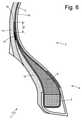
図5および図6に示す実施形態によれば、トランスポンダ13(スリーブ17内に含まれている)は、ボディプライ3のフラップ(すなわち、ボディプライ3の、「U」字形に折りたたまれたビード4の周りのゾーン)においてボディプライ3と接触するように配置されている。ボディプライ3の各フラップにおいて、ボディプライ3の縁部19(すなわち、終端部)は、ボディプライ3自体の中間部分に寄りかかっている。トランスポンダ13は、ボディプライ3の縁部19(すなわち、終端部)の径方向でより内側に配置されている。そして、トランスポンダ13は、径方向でボディプライ3の縁部19(終端部)とビード4との間に配置されている。径方向距離Dは、一般に10mmに等しく、またいずれにせよ7mmより大きく、トランスポンダ13とボディプライ3の縁部19(終端部)との間に設けられている。 According to the embodiments shown in FIGS. 5 and 6, the transponder 13 (included in the sleeve 17) is a flap of the body ply 3 (ie, the
トランスポンダ13は、ビード4の径方向でより外側に、したがってビードフィラー6の径方向でより外側に配置されている。さらに、トランスポンダ13は、サイドウォール11および摩耗ゴムストリップ12の径方向でより内側で、摩耗ゴムストリップ12の終端部の近傍(すなわち、サイドウォール11および摩耗ゴムストリップ12の両方が存在するゾーン)に配置されている。 The
図5に示す実施形態で、トランスポンダ13(スリーブ17内に含まれている)は、軸方向でボディプライ3のフラップの内側に配置されているため、両側で横方向に(換言すると、軸方向に、すなわち、空気入りタイヤ1の回転軸に平行して)ボディプライ3に隣接する。換言すると、トランスポンダ13は、両側で(換言すると、右側および左側で、すなわち、内側および外側の両方で)ボディプライ3の対応する部分と接触する。 In the embodiment shown in FIG. 5, since the transponder 13 (included in the sleeve 17) is arranged inside the flap of the body ply 3 in the axial direction, the
図6に示す実施形態で、トランスポンダ13(スリーブ17内に含まれている)は、軸方向でボディプライ3のフラップの外部に配置されているため、横方向に(換言すると、軸方向に、すなわち、空気入りタイヤ1の回転軸に平行して)一方の側(内側)でボディプライ3に隣接し、反対側(外側)で摩耗ゴムストリップ12(図6に示すように)またはサイドウォール11(図示しない変形例による)に隣接する。換言すると、トランスポンダ13は、ボディプライ3の対応する部分と内側で接触し、摩耗ゴムストリップ12(図6に示すように)またはサイドウォール11(図示しない変形例による)の対応する部分と外側で接触する。 In the embodiment shown in FIG. 6, since the transponder 13 (included in the sleeve 17) is arranged outside the flap of the body ply 3 in the axial direction, the
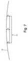
前述したように、トランスポンダ13は周方向に配置され、直方体形状を有し、空気入りタイヤ1の内部で空気入りタイヤ1の他のすべての構成要素の環状の進行に追従しない。その結果、図7に示すように、トランスポンダ13とボディプライ3の縁部19(終端部)との間の径方向距離Dは、トランスポンダ13が矩形の進行を有し、一方ボディプライ3の縁部19(終端部)が環状の進行を有するため、トランスポンダ13の全範囲に沿って連続的に可変である(たとえ最大で1~3mmであっても)。この点に関して、トランスポンダ13とボディプライ3の縁部19(終端部)との間の最小(すなわち、可能な限り最小の)径方向距離Dは、一般に10mmに等しく、またいずれにせよ7mmより大きくすることが重要である。その結果、トランスポンダ13とボディプライ3の縁部19(終端部)との間の最大(すなわち、可能な限り最大の)径方向距離Dは、これらの値(例えば、一般に12mmに等しく、またいずれにせよ9mmより大きい)より(わずかに)大きい。 As mentioned above, the
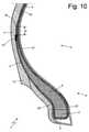
図1、図5及び図6に示す実施形態で、空気入りタイヤ1は、2つのビード4の周りに2つのフラップを形成する単一のボディプライ3を備える。図8、図9及び図10に示す代替実施形態では、空気入りタイヤ1が、2つのビード4の周りに2つのフラップを形成するボディプライ3(メイン)と、ボディプライ3よりも小さい更なる(二次又は追加の)ボディプライ20と、を備える。ボディプライ20は、ボディプライ3の上に重ね合わされ、2つのビード4の周りを回るが、ボディプライ3のように完全なフラップは形成しない。 In the embodiments shown in FIGS. 1, 5 and 6, the pneumatic tire 1 comprises a
ボディプライ3(および/またはボディプライ20)には、ボディプライ3の限定された部分に適用される局所的な補強要素を設けることができることが重要である。例えば、ボディプライ3には、ビード4近傍に適用される布製補強材、および/または、同様にビード4近傍に適用されるカレンダー加工された「スキージ」を設けることができる。この場合、このような補強要素はボディプライ3の一体部分となる。そのため、トランスポンダ13を、このような補強要素においても、ボディプライ3と接触して配置することができる。 It is important that the body ply 3 (and / or the body ply 20) can be provided with a local reinforcing element applied to a limited portion of the
空気入りタイヤ1は、「標準」タイプまたは「非標準」タイプであってよい。例えば、空気入りタイヤ1は、「ランフラット」タイプ、「スポンジ」タイプ(すなわち、音響効果を有するスポンジ体を内部に備える)、または「シーラント」タイプ(すなわち、任意の穴を塞ぐことができるシール剤を備える)であってよい。 The pneumatic tire 1 may be of "standard" type or "non-standard" type. For example, the pneumatic tire 1 may be a "runflat" type, a "sponge" type (ie, having a sponge body having an acoustic effect inside), or a "sealant" type (ie, a seal capable of closing any hole). It may be equipped with an agent).
本明細書に記載の実施形態は、本発明の保護範囲から逸脱することなく、相互に組み合わせることができる。 The embodiments described herein can be combined with each other without departing from the scope of protection of the invention.
上述の空気入りタイヤ1は、多くの利点を有する。 The pneumatic tire 1 described above has many advantages.
何よりもまず、前述の空気入りタイヤ1において、トランスポンダ13の位置は、トランスポンダ13が(空気入りタイヤ1の製造中および空気入りタイヤ1の使用中の両方において)受ける応力および変形を最小限に抑えることを可能とし、また同時にトランスポンダ13の無線周波通信の障害および干渉を最小限に抑えることができる(このように、空気入りタイヤ1が金属リム上に取り付けられていない場合には3メートルを超える距離でトランスポンダを読み取り可能であり、空気入りタイヤ1が金属リム上に取り付けられている場合には2メートルを超える距離でトランスポンダ13を読み取り可能である)。 First and foremost, in the aforementioned pneumatic tire 1, the position of the
さらに、上述の空気入りタイヤ1において、(トランスポンダ13が空気入りタイヤ1内に沈められた「異物」であるにもかかわらず)トランスポンダ13の存在は、空気入りタイヤ1自体の性能および耐久性(または動作寿命)に悪影響を及ぼすことはない。 Further, in the pneumatic tire 1 described above, the presence of the transponder 13 (despite the "foreign matter" submerged in the pneumatic tire 1) is due to the performance and durability of the pneumatic tire 1 itself (despite the fact that the
図5および図9に示す実施形態で、トランスポンダ13は、ボディプライ3の層のより内側に位置する限り外部からより良好に保護される。図6および図10に示す実施形態では、ボディプライ3の局所的な変形が回避される。トランスポンダ13を収容するための空間は、完全に、サイドウォール11(これは、ゴムの厚い層で作られているために大きな変形能力を有する)のみを局所的に変形させることで形成されている。そのため、トランスポンダ13においてボディプライ3の内部に空気を取り込むリスクは、完全に回避される。 In the embodiments shown in FIGS. 5 and 9, the
最後に、ボディプライ3がまだ完全に平坦な状態であるときに(すなわち、ボディプライ3を形成ドラムの周囲に巻き付ける前に)、トランスポンダ1をボディプライ3に接着させて製造することができるため、またはサイドウォール自体を取り付ける前に、トランスポンダ1をサイドウォール11に接着させて製造することができるため、上述の空気入りタイヤ1の構造は単純である。明らかに、トランスポンダ1は、図6および10に示す実施形態においてのみサイドウォール11に接着させることができる。一方、トランスポンダ1は、全ての実施形態においてボディプライ3に接着させることができる。 Finally, because the transponder 1 can be manufactured by adhering it to the body ply 3 when the body ply 3 is still in a completely flat state (ie, before wrapping the body ply 3 around the forming drum). , Or because the transponder 1 can be manufactured by adhering it to the
1 空気入りタイヤ
2 カーカス
3 ボディプライ
4 ビード
5 ビードコア
6 ビードフィラー
7 トレッド
8 トレッドベルト
9 トレッドプライ
10 インナーライナー
11 サイドウォール
12 摩耗ゴムストリップ
13 トランスポンダ
14 電子回路
15 アンテナ
16 支持体
17 スリーブ
18 ストリップ
19 縁部
20 ボディプライ
L 長さ
W 幅
T 厚さ
D 距離1
Claims (11)
Translated fromJapanese少なくとも1つのボディプライ(3)からなるトロイダルカーカス(2)であって、前記ボディプライ(3)は、部分的に折りたたまれているために2つの側面フラップを備え、各フラップにおいて、前記ボディプライ(3)の縁部(19)は、前記ボディプライ(3)自体の中間部分に当接するトロイダウカーカス(2)と、
2つの環状ビード(4)であって、各環状ビード(4)は、前記ボディプライ(3)で囲まれ、ビードコア(5)およびビードフィラー(6)を備える環状ビード(4)と、
環状トレッド(7)と、
前記トレッド(7)と前記ビード(4)との間で前記ボディプライ(3)の軸方向外側に配置された一対のサイドウォール(11)と、
前記ボディプライ(3)の軸方向外側で、前記サイドウォール(11)の径方向でより内側に、前記ビード(4)に配置された一対の摩耗ゴムストリップ(12)と、
トランスポンダ(13)であって、前記トランスポンダ(13)は、前記ボディプライ(3)のフラップに、前記ボディプライ(3)と接触して配置され、前記ボディプライ(3)の縁部(19)の径方向でより内側に配置されたトランスポンダ(13)と、を備え、
前記トランスポンダ(13)が、径方向で前記ボディプライ(3)の前記縁部(19)と前記ビード(4)との間に配置され、
7mmより大きい径方向距離(D)が、前記トランスポンダ(13)と前記ボディプライ(3)の前記縁部(19)との間に設けられており、
前記トランスポンダ(13)は、前記ビード(4)の径方向でより外側に、したがって前記ビードフィラー(6)の径方向でより外側に配置されていることを特徴とする、空気入りタイヤ(1)。Pneumatic tire (1)
A toroidal carcass (2) consisting of at least one body ply (3), wherein the body ply (3) has two side flaps because it is partially folded, and at each flap, the body ply. The edge portion (19) of (3) includes a Trojan carcass (2) that abuts on an intermediate portion of the body ply (3) itself.
Two annular beads (4), each annular bead (4) being surrounded by the body ply (3) and comprising a bead core (5) and a bead filler (6), and an annular bead (4).
Circular tread (7) and
A pair of sidewalls (11) arranged axially outside the body ply (3) between the tread (7) and the bead (4).
A pair of wear rubber strips (12) arranged on the bead (4) on the outer side in the axial direction of the body ply (3) and on the inner side in the radial direction of the sidewall(11) .
A transponder (13), wherein the transponder (13) is arranged in contact with the body ply (3) on the flap of the body ply (3), and the edge portion (19) of the body ply (3) is arranged. With a transponder (13) located more inward in the radial direction of
The transponder (13) is radially disposed between the edge (19) of the body ply (3) and the bead (4).
A radial distance (D) greater than 7 mm is provided between the transponder (13) and the edge (19) of the body ply (3).
The pneumatic tire (1) is characterizedin that the transponder (13) is arranged radially outward of the bead (4) and thus outward in the radial direction of the bead filler (6). ..
Applications Claiming Priority (3)
| Application Number | Priority Date | Filing Date | Title |
|---|---|---|---|
| IT102018000004917 | 2018-04-27 | ||
| IT102018000004917AIT201800004917A1 (en) | 2018-04-27 | 2018-04-27 | TIRE FITTED WITH A TRANSPONDER |
| PCT/IB2019/053165WO2019207419A1 (en) | 2018-04-27 | 2019-04-17 | Pneumatic tyre equipped with a transponder |
Publications (2)
| Publication Number | Publication Date |
|---|---|
| JP2021518829A JP2021518829A (en) | 2021-08-05 |
| JP7019839B2true JP7019839B2 (en) | 2022-02-15 |
Family
ID=62952323
Family Applications (1)
| Application Number | Title | Priority Date | Filing Date |
|---|---|---|---|
| JP2020560177AActiveJP7019839B2 (en) | 2018-04-27 | 2019-04-17 | Pneumatic tire with transponder |
Country Status (6)
| Country | Link |
|---|---|
| US (2) | US11932059B2 (en) |
| EP (1) | EP3784503A1 (en) |
| JP (1) | JP7019839B2 (en) |
| CN (1) | CN112236320A (en) |
| IT (1) | IT201800004917A1 (en) |
| WO (1) | WO2019207419A1 (en) |
Families Citing this family (5)
| Publication number | Priority date | Publication date | Assignee | Title |
|---|---|---|---|---|
| IT201800004917A1 (en)* | 2018-04-27 | 2019-10-27 | TIRE FITTED WITH A TRANSPONDER | |
| JP6594504B1 (en)* | 2018-10-03 | 2019-10-23 | Toyo Tire株式会社 | tire |
| JP6667045B1 (en)* | 2019-11-27 | 2020-03-18 | 横浜ゴム株式会社 | Pneumatic tire |
| JP7591985B2 (en)* | 2021-06-30 | 2024-11-29 | 株式会社ブリヂストン | tire |
| JP2025143907A (en)* | 2024-03-19 | 2025-10-02 | 横浜ゴム株式会社 | pneumatic tires |
Citations (9)
| Publication number | Priority date | Publication date | Assignee | Title |
|---|---|---|---|---|
| JP2000108619A (en) | 1998-10-01 | 2000-04-18 | Yokohama Rubber Co Ltd:The | Auxiliary part for tire transponder |
| US20100122757A1 (en) | 2008-11-18 | 2010-05-20 | Robert Edward Lionetti | Tire and electronic device assembly |
| JP2011525654A (en) | 2008-06-23 | 2011-09-22 | ソシエテ ド テクノロジー ミシュラン | Rubber-coated electronic component manufacturing method and manufacturing plant |
| US20120291936A1 (en) | 2011-05-19 | 2012-11-22 | Robert Edward Lionetti | Embedded transponder and tire assembly and method of construction thereof |
| US20140049375A1 (en) | 2012-08-20 | 2014-02-20 | John Michael Fenkanyn | Stacked tire rfid reader system and method |
| JP2015223918A (en) | 2014-05-27 | 2015-12-14 | 株式会社ブリヂストン | Pneumatic tire provided with electronic component and method for manufacturing same |
| JP2016049920A (en) | 2014-09-01 | 2016-04-11 | 株式会社ブリヂストン | tire |
| CN206584389U (en) | 2016-11-15 | 2017-10-24 | 刘台华 | Inductive coupling type RFID antenna device |
| WO2019054227A1 (en) | 2017-09-12 | 2019-03-21 | 住友ゴム工業株式会社 | Pneumatic tire |
Family Cites Families (12)
| Publication number | Priority date | Publication date | Assignee | Title |
|---|---|---|---|---|
| US5181975A (en)* | 1991-03-27 | 1993-01-26 | The Goodyear Tire & Rubber Company | Integrated circuit transponder with coil antenna in a pneumatic tire for use in tire identification |
| JP4183032B2 (en)* | 2002-08-30 | 2008-11-19 | 横浜ゴム株式会社 | Pneumatic tire equipped with a film-like electronic device and method for attaching the film-like electronic device |
| FR2936185B1 (en)* | 2008-09-25 | 2011-09-23 | Michelin Soc Tech | PNEUMATIC HAVING A DELETED ANTENNA ORGAN |
| KR101312841B1 (en) | 2011-12-15 | 2013-09-30 | 금호타이어 주식회사 | Tire with RFID antenna |
| FR3037200B1 (en)* | 2015-06-03 | 2017-05-26 | Michelin & Cie | RADIOFREQUENCY TRANSPONDER FOR PNEUMATIC |
| JP6573565B2 (en)* | 2016-03-22 | 2019-09-11 | Kddi株式会社 | Device control apparatus, consideration calculation method, and device control system |
| IT201800004917A1 (en)* | 2018-04-27 | 2019-10-27 | TIRE FITTED WITH A TRANSPONDER | |
| IT201800004925A1 (en)* | 2018-04-27 | 2019-10-27 | TIRE FITTED WITH A TRANSPONDER | |
| EP3793845B1 (en)* | 2018-05-17 | 2024-07-03 | Compagnie Generale Des Etablissements Michelin | Tyre for a heavy goods vehicle, equipped with a radio-frequency communication module |
| JP6582104B1 (en)* | 2018-10-03 | 2019-09-25 | Toyo Tire株式会社 | Tire manufacturing method |
| JP6594505B1 (en)* | 2018-10-03 | 2019-10-23 | Toyo Tire株式会社 | Tire and tire manufacturing method |
| JP6594504B1 (en)* | 2018-10-03 | 2019-10-23 | Toyo Tire株式会社 | tire |
- 2018
- 2018-04-27ITIT102018000004917Apatent/IT201800004917A1/enunknown
- 2019
- 2019-04-17USUS17/050,570patent/US11932059B2/enactiveActive
- 2019-04-17WOPCT/IB2019/053165patent/WO2019207419A1/ennot_activeCeased
- 2019-04-17CNCN201980039020.0Apatent/CN112236320A/enactivePending
- 2019-04-17JPJP2020560177Apatent/JP7019839B2/enactiveActive
- 2019-04-17EPEP19724932.9Apatent/EP3784503A1/enactivePending
- 2024
- 2024-02-15USUS18/442,875patent/US20240181818A1/enactivePending
Patent Citations (10)
| Publication number | Priority date | Publication date | Assignee | Title |
|---|---|---|---|---|
| JP2000108619A (en) | 1998-10-01 | 2000-04-18 | Yokohama Rubber Co Ltd:The | Auxiliary part for tire transponder |
| JP2011525654A (en) | 2008-06-23 | 2011-09-22 | ソシエテ ド テクノロジー ミシュラン | Rubber-coated electronic component manufacturing method and manufacturing plant |
| US20100122757A1 (en) | 2008-11-18 | 2010-05-20 | Robert Edward Lionetti | Tire and electronic device assembly |
| US20120291936A1 (en) | 2011-05-19 | 2012-11-22 | Robert Edward Lionetti | Embedded transponder and tire assembly and method of construction thereof |
| US20140049375A1 (en) | 2012-08-20 | 2014-02-20 | John Michael Fenkanyn | Stacked tire rfid reader system and method |
| JP2014038627A (en) | 2012-08-20 | 2014-02-27 | The Goodyear Tire & Rubber Co | Laminated tire rfid reader device and method |
| JP2015223918A (en) | 2014-05-27 | 2015-12-14 | 株式会社ブリヂストン | Pneumatic tire provided with electronic component and method for manufacturing same |
| JP2016049920A (en) | 2014-09-01 | 2016-04-11 | 株式会社ブリヂストン | tire |
| CN206584389U (en) | 2016-11-15 | 2017-10-24 | 刘台华 | Inductive coupling type RFID antenna device |
| WO2019054227A1 (en) | 2017-09-12 | 2019-03-21 | 住友ゴム工業株式会社 | Pneumatic tire |
Also Published As
| Publication number | Publication date |
|---|---|
| WO2019207419A1 (en) | 2019-10-31 |
| IT201800004917A1 (en) | 2019-10-27 |
| JP2021518829A (en) | 2021-08-05 |
| EP3784503A1 (en) | 2021-03-03 |
| US20240181818A1 (en) | 2024-06-06 |
| CN112236320A (en) | 2021-01-15 |
| US20210237521A1 (en) | 2021-08-05 |
| US11932059B2 (en) | 2024-03-19 |
Similar Documents
| Publication | Publication Date | Title |
|---|---|---|
| JP7024118B2 (en) | Pneumatic tire with transponder | |
| JP7019839B2 (en) | Pneumatic tire with transponder | |
| JP2020055453A (en) | Tire and tire manufacturing method | |
| JP7453241B2 (en) | Pneumatic tire with transponder | |
| US12227038B2 (en) | Pneumatic tyre equipped with a transponder | |
| EP4422854B1 (en) | Method of producing a tyre equipped with an electronic device | |
| RU2796079C2 (en) | Pneumatic tire equipped with a transponder | |
| RU2798384C2 (en) | Pneumatic tire equipped with a transponder | |
| WO2025099654A1 (en) | Pneumatic tyre equipped with an electronic device | |
| WO2025099652A1 (en) | Pneumatic tyre equipped with an electronic device | |
| IT201900001559A1 (en) | TIRE FITTED WITH A TRANSPONDER |
Legal Events
| Date | Code | Title | Description |
|---|---|---|---|
| A621 | Written request for application examination | Free format text:JAPANESE INTERMEDIATE CODE: A621 Effective date:20201110 | |
| A977 | Report on retrieval | Free format text:JAPANESE INTERMEDIATE CODE: A971007 Effective date:20211109 | |
| A131 | Notification of reasons for refusal | Free format text:JAPANESE INTERMEDIATE CODE: A131 Effective date:20211214 | |
| A521 | Request for written amendment filed | Free format text:JAPANESE INTERMEDIATE CODE: A523 Effective date:20211227 | |
| TRDD | Decision of grant or rejection written | ||
| A01 | Written decision to grant a patent or to grant a registration (utility model) | Free format text:JAPANESE INTERMEDIATE CODE: A01 Effective date:20220201 | |
| A61 | First payment of annual fees (during grant procedure) | Free format text:JAPANESE INTERMEDIATE CODE: A61 Effective date:20220202 | |
| R150 | Certificate of patent or registration of utility model | Ref document number:7019839 Country of ref document:JP Free format text:JAPANESE INTERMEDIATE CODE: R150 | |
| S531 | Written request for registration of change of domicile | Free format text:JAPANESE INTERMEDIATE CODE: R313531 | |
| R350 | Written notification of registration of transfer | Free format text:JAPANESE INTERMEDIATE CODE: R350 | |
| R250 | Receipt of annual fees | Free format text:JAPANESE INTERMEDIATE CODE: R250 |