Movatterモバイル変換


[0]ホーム

URL:


JP7019207B2 - Lighting equipment - Google Patents

Lighting equipment
Download PDF

Info

Publication number
JP7019207B2
JP7019207B2JP2020094729AJP2020094729AJP7019207B2JP 7019207 B2JP7019207 B2JP 7019207B2JP 2020094729 AJP2020094729 AJP 2020094729AJP 2020094729 AJP2020094729 AJP 2020094729AJP 7019207 B2JP7019207 B2JP 7019207B2
Authority
JP
Japan
Prior art keywords
led
hole
cylinder
circuit board
board
Prior art date
Legal status (The legal status is an assumption and is not a legal conclusion. Google has not performed a legal analysis and makes no representation as to the accuracy of the status listed.)
Active
Application number
JP2020094729A
Other languages
Japanese (ja)
Other versions
JP2020126863A (en
Inventor
大輔 尾形
和志 酒井
Current Assignee (The listed assignees may be inaccurate. Google has not performed a legal analysis and makes no representation or warranty as to the accuracy of the list.)
Iris Ohyama Inc
Original Assignee
Iris Ohyama Inc
Priority date (The priority date is an assumption and is not a legal conclusion. Google has not performed a legal analysis and makes no representation as to the accuracy of the date listed.)
Filing date
Publication date
Family has litigation
First worldwide family litigation filedlitigationCriticalhttps://patents.darts-ip.com/?family=72084165&utm_source=google_patent&utm_medium=platform_link&utm_campaign=public_patent_search&patent=JP7019207(B2)"Global patent litigation dataset” by Darts-ip is licensed under a Creative Commons Attribution 4.0 International License.
Application filed by Iris Ohyama IncfiledCriticalIris Ohyama Inc
Priority to JP2020094729ApriorityCriticalpatent/JP7019207B2/en
Publication of JP2020126863ApublicationCriticalpatent/JP2020126863A/en
Priority to JP2022010371Aprioritypatent/JP2022050692A/en
Application grantedgrantedCritical
Publication of JP7019207B2publicationCriticalpatent/JP7019207B2/en
Priority to JP2023010995Aprioritypatent/JP7632900B2/en
Priority to JP2023196189Aprioritypatent/JP2024003262A/en
Activelegal-statusCriticalCurrent
Anticipated expirationlegal-statusCritical

Links

Images

Landscapes

Description

Translated fromJapanese

本発明は、LED素子と電源回路ユニットとを備える照明装置に関する。 The present invention relates to a lighting device including an LED element and a power supply circuit unit.

近年、環境意識の高まりから、省電力化に優れたLED素子を光源に使用したLED照明装置が盛んに用いられ、LED素子をLED基板に実装してなるLEDモジュールを安価に提供する技術が提案されている(例えば特許文献1)。
特許文献1の技術は、LED基板上の配線パターンと電気的に接続するように金属ピンをLED基板の貫通孔に嵌挿するものであり、外部との電気的接続を金属ピンを介して行うため、製造工数を削減できる。
In recent years, due to heightened environmental awareness, LED lighting devices that use LED elements with excellent power saving as a light source have been actively used, and a technology to provide LED modules in which LED elements are mounted on an LED substrate at low cost has been proposed. (For example, Patent Document 1).
The technique ofPatent Document 1 is to insert a metal pin into a through hole of an LED board so as to be electrically connected to a wiring pattern on the LED board, and to electrically connect to the outside through the metal pin. Therefore, the manufacturing man-hours can be reduced.

特開2011-258606号公報Japanese Unexamined Patent Publication No. 2011-25806

上記技術では、LEDモジュール以外の外部(例えば、電源回路ユニット等である。)と金属ピン(導電体)との電気的接続が具体的でなく、接続すべき外部の端子の形態によっては製造工数が削減できない場合も生じ得る。
本発明は、導電体を用いて製造工数を削減できる照明装置を提供することを目的とする。
In the above technology, the electrical connection between the external (for example, a power supply circuit unit, etc.) other than the LED module and the metal pin (conductor) is not specific, and the manufacturing man-hours depend on the form of the external terminal to be connected. May not be reduced.
An object of the present invention is to provide a lighting device that can reduce manufacturing man-hours by using a conductor.

本発明は、LED素子がLED基板に実装されてなるLEDモジュールと、複数個の回路部品が回路基板に実装されてなり且つ前記LED素子に電力を供給する電源回路ユニットとを備える照明装置において、前記LED基板と前記回路基板とを電気的に接続する導電体が前記LED基板と前記回路基板との一方の基板に設けられ、前記LED基板と前記回路基板との他方の基板に、前記導電体が挿通するための貫通孔と、前記貫通孔を塞ぎ且つ前記導電体の前記貫通孔の通過に伴って弾性変形する導電バネ片とが設けられ、前記LED基板と前記回路基板は平行な状態であって一部が表裏方向に重なり、前記一方の基板に設けられた前記導電体は前記一方の基板における前記他方の基板と表裏方向に重なる部分から前記貫通孔を通過するように立設し、前記LED基板と前記回路基板とを近づけることで、前記導電体が前記貫通孔を通過して前記導電バネ片と電気的に接続する。 The present invention comprises an LED module in which an LED element is mounted on an LED substrate, and a power supply circuit unit in which a plurality of circuit components are mounted on the circuit board and power is supplied to the LED element. A conductor that electrically connects the LED board and the circuit board is provided on one board of the LED board and the circuit board, and the conductor is provided on the other board of the LED board and the circuit board. A through hole through which the conductor is inserted and a conductive spring piece that closes the through hole and elastically deforms as the conductor passes through the through hole are provided, and the LED substrate and the circuit board are in a parallel state. A part of the conductor overlaps in the front and back directions, and the conductor provided on the one substrate is erected so as to pass through the through hole from a portion of the one substrate that overlaps with the other substrate in the front and back directions. By bringing the LED substrate close to the circuit board, the conductor passes through the through hole and is electrically connected to the conductive spring piece.

上記構成によれば、導電体と電気的接続を行う相手側に導電バネ片を設けているので、導電体を相手側の基板の貫通孔に相対的に挿通させることで、電気的接続を確実に行うことができる。 According to the above configuration, since the conductive spring piece is provided on the mating side that makes an electrical connection with the conductor, the conductive spring piece is relatively inserted through the through hole of the substrate on the mating side to ensure the electrical connection. Can be done.

第1の実施形態に係る照明装置の正面図である。It is a front view of the lighting apparatus which concerns on 1st Embodiment.第1の実施形態に係る照明装置の断面正面図である。It is sectional front view of the lighting apparatus which concerns on 1st Embodiment.第1の実施形態において、(a)は照明装置から筐体を取り外した状態を表側から見た斜視図であり、(b)は照明装置から筐体を取り外した状態を裏側から見た斜視図である。In the first embodiment, (a) is a perspective view of a state in which the housing is removed from the lighting device from the front side, and (b) is a perspective view of a state in which the housing is removed from the lighting device from the back side. Is.第1の実施形態において、(a)はベース部材に電源回路ユニットとLEDモジュールとが取付けられた状態を表側から見た斜視図であり、(b)はベース部材に電源回路ユニットとLEDモジュールとが取付けられた状態を裏側から見た斜視図である。In the first embodiment, (a) is a perspective view of a state in which the power supply circuit unit and the LED module are attached to the base member from the front side, and (b) is a state in which the power supply circuit unit and the LED module are attached to the base member. It is a perspective view which looked at the state which was attached from the back side.第1の実施形態において、(a)はベース部材に電源回路ユニットとLEDモジュールとが取付けられた状態の断面を表側から見た斜視図であり、(b)はベース部材に電源回路ユニットとLEDモジュールとが取付けられた状態の断面を裏側から見た斜視図である。In the first embodiment, (a) is a perspective view of a cross section of a state in which the power supply circuit unit and the LED module are attached to the base member from the front side, and (b) is a perspective view of the power supply circuit unit and the LED attached to the base member. It is a perspective view which looked at the cross section in the state which a module is attached from the back side.(a)は第2の実施形態に係る照明装置を表側から見た斜視図であり、(b)は第2の実施形態に係る照明装置を裏側から見た斜視図である。(A) is a perspective view of the lighting device according to the second embodiment as viewed from the front side, and (b) is a perspective view of the lighting device according to the second embodiment as viewed from the back side.第2の実施形態において、(a)は照明装置から透光性カバーを取り外した状態を表側から見た斜視図であり、(b)は(a)の状態から内カバーを取り外した状態を表側から見た斜視図である。In the second embodiment, (a) is a perspective view of a state in which the translucent cover is removed from the lighting device from the front side, and (b) is a state in which the inner cover is removed from the state of (a) on the front side. It is a perspective view seen from.第2の実施形態において、(a)は照明装置を裏側から見た斜視図であり、(b)は(a)の状態から裏カバーを取り外した状態を裏側から見た斜視図である。In the second embodiment, (a) is a perspective view of the lighting device as viewed from the back side, and (b) is a perspective view of the state in which the back cover is removed from the state of (a) as viewed from the back side.第2の実施形態において、(a)は照明装置から裏カバーを取り外した状態を裏側から見た図であり、(b)は照明装置から透光性カバー及び内カバーを取り外した状態を表側から見た図である。In the second embodiment, (a) is a view from the back side of the state in which the back cover is removed from the lighting device, and (b) is a state in which the translucent cover and the inner cover are removed from the lighting device from the front side. It is a figure that I saw.第2の実施形態において、電源回路ユニットとLEDモジュールとの電気的接続を説明する図である。In the second embodiment, it is a figure explaining the electrical connection between a power supply circuit unit and an LED module.第2の実施形態において、電源回路ユニットとLEDモジュールとの電気的接続を説明する断面図である。In the second embodiment, it is sectional drawing explaining the electrical connection between a power supply circuit unit and an LED module.第2の実施形態において、LEDモジュールの固定を説明する断面図である。It is sectional drawing explaining the fixing of the LED module in 2nd Embodiment.第3の実施形態に係る照明装置の正面図である。It is a front view of the lighting apparatus which concerns on 3rd Embodiment.第3の実施形態に係る照明装置の分解斜視図である。It is an exploded perspective view of the lighting apparatus which concerns on 3rd Embodiment.第3の実施形態に係る照明装置の断面図である。It is sectional drawing of the lighting apparatus which concerns on 3rd Embodiment.第3の実施形態において、(a)は図13のA-A断面を矢印方向から見た図であり、(b)は図13のB-B断面を矢印方向から見た図である。In the third embodiment, (a) is a view of the cross section AA of FIG. 13 viewed from the direction of the arrow, and (b) is a view of the cross section BB of FIG. 13 viewed from the direction of the arrow.第3の実施形態において、(a)は筒体を透光性カバー側から見た斜視図であり、(b)は筒体を口金側から見た斜視図である。In the third embodiment, (a) is a perspective view of the tubular body seen from the translucent cover side, and (b) is a perspective view of the tubular body seen from the base side.第4の実施形態に係る照明装置の分解斜視図である。It is an exploded perspective view of the lighting apparatus which concerns on 4th Embodiment.第4の実施形態に係る照明装置の断面図である。It is sectional drawing of the lighting apparatus which concerns on 4th Embodiment.第4の実施形態において、(a)は図13のA-A断面に相当する断面を矢印方向から見た図であり、(b)は図13のB-B断面に相当する断面を矢印方向から見た図である。In the fourth embodiment, (a) is a view of a cross section corresponding to the AA cross section of FIG. 13 viewed from the arrow direction, and (b) is a view of the cross section corresponding to the BB cross section of FIG. 13 in the arrow direction. It is a figure seen from.第4の実施形態において、(a)は筒体を透光性カバー側から見た斜視図であり、(b)は筒体を口金側から見た斜視図である。In the fourth embodiment, (a) is a perspective view of the tubular body seen from the translucent cover side, and (b) is a perspective view of the tubular body seen from the base side.

<概要>
実施形態の一態様に係る照明装置は、LED素子がLED基板に実装されてなるLEDモジュールと、複数個の回路部品が回路基板に実装されてなり且つ前記LED素子に電力を供給する電源回路ユニットとを備える照明装置において、前記LED基板と前記回路基板とを電気的に接続する導電体が前記LED基板と前記回路基板との一方の基板に設けられ、前記LED基板と前記回路基板との他方の基板に、前記導電体が挿通するための貫通孔と、前記貫通孔を塞ぎ且つ前記導電体の前記貫通孔の通過に伴って弾性変形する導電バネ片とが設けられ、前記LED基板と前記回路基板は平行な状態であって一部が表裏方向に重なり、前記一方の基板に設けられた前記導電体は前記一方の基板における前記他方の基板と表裏方向に重なる部分から前記貫通孔を通過するように立設し、前記LED基板と前記回路基板とを近づけることで、前記導電体が前記貫通孔を通過して前記導電バネ片と電気的に接続する。
実施形態の別態様に係る照明装置において、前記一方の基板は前記回路基板であり、前記他方の基板は前記LED基板であり、前記導電バネ片は前記LED基板における前記回路基板と反対側の面に設けられている。
実施形態の別態様に係る照明装置において、表面に前記LED基板が装着され、裏面に前記回路基板が装着される板状のベース部材を備え、前記LED基板は円板状をし、前記LED基板の周縁部分に近い部位が締結具により前記ベース部材に締結されている。
実施形態の別態様に係る照明装置において、前記導電体は、板状又は棒状をし、前記導電バネ片は、1枚の矩形状の金属板を湾曲させてなり、前記金属板の長手方向の中央に前記導電体通過用の孔を有し、前記孔の両側が「く」字状に湾曲している。
明細書の一態様に係る照明装置は、LED素子がLED基板に実装されてなるLEDモジュールと、複数個の回路部品が回路基板に実装されてなり且つ前記LED素子に電力を供給する電源回路ユニットとを備える照明装置において、前記LED基板と前記回路基板とを電気的に接続する導電体が前記LED基板と前記回路基板との一方の基板に設けられ、前記LED基板と前記回路基板との他方の基板に、前記導電体が挿通するための貫通孔と、前記貫通孔を塞ぎ且つ前記導電体の前記貫通孔の通過に伴って弾性変形する導電バネ片とが設けられ、前記他方の基板は、前記一方の基板が存在する側の面がベース部材に当接する部分で、締結具により前記ベース部材に締結されている。
明細書の別態様に係る照明装置において、前記一方の基板は前記回路基板であり、前記他方の基板は前記LED基板である。
明細書の別態様に係る照明装置において、前記LED基板は円板状をし、前記LED基板の周縁部分に近い部位が前記締結具により前記ベース部材に締結されている。これにより、LED素子から出射された光を遮るのを少なくできる。
明細書の別態様に係る照明装置において、前記締結具はねじ体である。これにより、容易に他方の基板をベース部材に固定できる。
<Overview>
The lighting device according to one embodiment includes an LED module in which an LED element is mounted on an LED substrate, and a power supply circuit unit in which a plurality of circuit components are mounted on the circuit board and power is supplied to the LED element. In a lighting device including, a conductor for electrically connecting the LED board and the circuit board is provided on one board of the LED board and the circuit board, and the other of the LED board and the circuit board is provided. The substrate is provided with a through hole through which the conductor is inserted, and a conductive spring piece that closes the through hole and elastically deforms as the conductor passes through the through hole. The circuit boards are in a parallel state and partly overlap in the front and back directions, and the conductor provided on the one substrate passes through the through hole from the portion of the one substrate that overlaps with the other substrate in the front and back directions. By bringing the LED board and the circuit board close to each other, the conductor passes through the through hole and is electrically connected to the conductive spring piece.
In the lighting device according to another embodiment of the embodiment, the one substrate is the circuit board, the other substrate is the LED substrate, and the conductive spring piece is a surface of the LED substrate opposite to the circuit board. It is provided in.
In the lighting device according to another embodiment of the embodiment, the LED substrate is mounted on the front surface and the circuit board is mounted on the back surface. The LED substrate has a disk shape and the LED substrate is mounted. A portion close to the peripheral portion of the base member is fastened to the base member by a fastener.
In the lighting device according to another embodiment of the embodiment, the conductor has a plate shape or a rod shape, and the conductive spring piece is formed by bending one rectangular metal plate in the longitudinal direction of the metal plate. It has a hole for passing the conductor in the center, and both sides of the hole are curved in a "dogleg" shape.
The lighting device according to one aspect of the specification includes an LED module in which an LED element is mounted on an LED substrate, and a power supply circuit unit in which a plurality of circuit parts are mounted on a circuit board and power is supplied to the LED element. In a lighting device including, a conductor for electrically connecting the LED board and the circuit board is provided on one board of the LED board and the circuit board, and the other of the LED board and the circuit board is provided. The substrate is provided with a through hole through which the conductor is inserted and a conductive spring piece that closes the through hole and elastically deforms as the conductor passes through the through hole. , The surface on the side where one of the substrates is present abuts on the base member, and is fastened to the base member by a fastener.
In the lighting device according to another aspect of the specification, the one substrate is the circuit board and the other substrate is the LED substrate.
In the lighting device according to another aspect of the specification, the LED substrate has a disk shape, and a portion near the peripheral edge portion of the LED substrate is fastened to the base member by the fastener. As a result, it is possible to reduce the amount of blocking the light emitted from the LED element.
In the lighting device according to another aspect of the specification, the fastener is a screw body. As a result, the other substrate can be easily fixed to the base member.

<第1の実施形態>
1.概要
第1の実施形態について図1~図5を用いて説明する。
第1の実施形態に係る照明装置1は、天井等のダクトレール(図示省略)に取り付けられて使用する、所謂、スポットライトである。
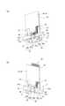
照明装置1は、図2に示すように、ベース部材2を備え、ベース部材2の表側にLEDモジュール3を、ベース部材2の裏側に電源回路ユニット4をそれぞれ有している。なお、電源回路ユニット4とLEDモジュール3とは金属ピン45により電気的に接続されている。
照明装置1は、ベース部材2に装着され且つLEDモジュール3を表側から覆うレンズ部材5と、ベース部材2、LEDモジュール3、電源回路ユニット4及びレンズ部材5を収容する筐体6と、照明装置1をダクトレールに取り付けるためのプラグボックス7と、プラグボックス7と筐体6とを連結するアーム8とをさらに備える。
<First Embodiment>
1. 1. Outline The first embodiment will be described with reference to FIGS. 1 to 5.
Thelighting device 1 according to the first embodiment is a so-called spotlight that is attached to a duct rail (not shown) such as a ceiling and used.
As shown in FIG. 2, thelighting device 1 includes abase member 2, anLED module 3 on the front side of thebase member 2, and a powersupply circuit unit 4 on the back side of thebase member 2. The powersupply circuit unit 4 and theLED module 3 are electrically connected by ametal pin 45.
Thelighting device 1 includes alens member 5 that is mounted on thebase member 2 and covers theLED module 3 from the front side, ahousing 6 that houses thebase member 2, theLED module 3, a powersupply circuit unit 4, and thelens member 5, and a lighting device. Further, aplug box 7 for attaching 1 to the duct rail and anarm 8 for connecting theplug box 7 and thehousing 6 are further provided.

2.各部構成
(1)ベース部材
主に、図4を用いて説明する。
ベース部材2は、円板状のベース部21と、ベース部21の裏面から裏側に延伸するフィン23を複数有するフィン部25と、ベース部材2をアーム8に取り付けるための取付部27を有する。
ベース部21は金属ピン45用の一対の貫通孔21aを中央部分に有している。フィン23は、複数本あり、ベース部21の中央部分を除いたその周辺部分に立設されている。取付部27は、ベース部21の裏面であってベース部21の中央を挟んだ2か所の部位から裏側へと延伸する延伸片27aと、延伸片27aに設けられ且つ筐体6の中心軸に向かうねじ孔27bとにより構成される。このねじ孔27bには、図2に示すように、アーム8と連結するねじ体11が螺合する。ベース部21の裏側の中央部分の空間には、図2及び図3に示すように、電源回路ユニット4が配される。
2. 2. Configuration of each part (1) Base member Mainly, FIG. 4 will be used for explanation.
Thebase member 2 has a disk-shapedbase portion 21, afin portion 25 having a plurality offins 23 extending from the back surface to the back side of thebase portion 21, and a mountingportion 27 for attaching thebase member 2 to thearm 8.
Thebase portion 21 has a pair of throughholes 21a for the metal pins 45 in the central portion. There are a plurality offins 23, and thefins 23 are erected in peripheral portions excluding the central portion of thebase portion 21. The mountingportion 27 is provided on the stretchedpiece 27a, which is the back surface of thebase portion 21 and extends from two portions sandwiching the center of thebase portion 21 to the back side, and the central axis of thehousing 6. It is composed of ascrew hole 27b toward the surface. As shown in FIG. 2, ascrew body 11 connected to thearm 8 is screwed into thescrew hole 27b. As shown in FIGS. 2 and 3, a powersupply circuit unit 4 is arranged in the space in the central portion on the back side of thebase portion 21.

(2)LEDモジュール
主に、図4の(a)及び図5の(a)を用いて説明する。
LEDモジュール3は、LED基板31と複数個のLED素子33とから構成される。LED基板31は金属ピン45用の貫通孔31aを有する。LEDモジュール3は金属ピン45と接触する金属バネ片35をLED基板31に有する。金属バネ片35は薄肉の矩形状の金属板を長手方向の中央で屈曲させてなる。金属バネ片35における屈曲部から一端部までが、図5の(a)に示すように、LED基板31に固定される固定部35aとなっている。金属バネ片35における屈曲部から他端部までが、図5の(a)に示すように、LED基板31の貫通孔31aを塞ぎ、金属ピン45の挿入(通過)に合わせて弾性変形する金属バネ片35bとなっている。
LED基板31は、図4の(a)に示すように、ベース部21の表面に裏面が接触する状態でねじ体37によりベース部21に固定されている。
(2) LED module The description will be mainly made with reference to FIG. 4A and FIG. 5A.
TheLED module 3 is composed of anLED substrate 31 and a plurality ofLED elements 33. TheLED substrate 31 has a throughhole 31a for themetal pin 45. TheLED module 3 has ametal spring piece 35 in contact with themetal pin 45 on theLED substrate 31. Themetal spring piece 35 is formed by bending a thin rectangular metal plate at the center in the longitudinal direction. As shown in FIG. 5A, themetal spring piece 35 from the bent portion to one end portion is a fixedportion 35a fixed to theLED substrate 31. As shown in FIG. 5A, themetal spring piece 35 from the bent portion to the other end is a metal that closes the throughhole 31a of theLED substrate 31 and elastically deforms in accordance with the insertion (passage) of themetal pin 45. It is aspring piece 35b.
As shown in FIG. 4A, theLED substrate 31 is fixed to thebase portion 21 by thescrew body 37 in a state where the back surface is in contact with the front surface of thebase portion 21.

(3)電源回路ユニット
図2から図5を用いて説明する。
電源回路ユニット4は、図2に示すように、回路部品が回路基板41に実装された状態で絶縁ボックス43に収容されてなる。電源回路ユニット4は、図5に示すように、絶縁ボックス43(図5では現れていない。)、ベース部21の貫通孔21a及びLED基板31の貫通孔31aを貫通して、LEDモジュール3の金属バネ片35と接触する金属ピン45を有している。ここでの回路基板41は、LED基板31と直交する状態で、絶縁ボックス43内に支持されている。なお、絶縁ボックス43はベース部材2のフィン23から放出される熱を遮断する機能も有する。
(3) Power Supply Circuit Unit A description will be given with reference to FIGS. 2 to 5.
As shown in FIG. 2, the powersupply circuit unit 4 is housed in an insulatingbox 43 with circuit components mounted on acircuit board 41. As shown in FIG. 5, the powersupply circuit unit 4 penetrates the insulating box 43 (not shown in FIG. 5), the throughhole 21a of thebase portion 21, and the throughhole 31a of theLED substrate 31, and theLED module 3 has a throughhole 31a. It has ametal pin 45 that comes into contact with themetal spring piece 35. Thecircuit board 41 here is supported in the insulatingbox 43 in a state orthogonal to theLED board 31. The insulatingbox 43 also has a function of blocking heat released from thefins 23 of thebase member 2.

(4)レンズ部材
図2及び図3を用いて説明する。
レンズ部材5は、図2及び図3に示すように、各LED素子33に対向して配される複数個のレンズ51と、レンズ51をLED素子33と反対側で連結する連結板53と、連結板53の外周縁からベース部21に向かって筒状に延伸する筒部55と、レンズ部材5をベース部材2に固定するための固定部57とを有している。
筒部55の内径はLED基板31の外径よりも大きい。固定部57は筒部55から筒部55の中心軸方向に凹入した部分で構成され、凹入部分にねじ用の溝が設けられている。
レンズ部材5は、固定部57の裏面がLED基板31の表面の周縁部に当接する状態でベース部21に固定される。なお、筒部55の高さはレンズ51とLED素子33との距離が所定値となるように設定されている。また、レンズ部材5の筒部55とベース部材2のベース部21との間の隙間には、図2に示すように、後述の表側筐体63の内鍔部63bが嵌る。
(4) Lens member This will be described with reference to FIGS. 2 and 3.
As shown in FIGS. 2 and 3, thelens member 5 includes a plurality oflenses 51 arranged to face eachLED element 33, and a connectingplate 53 connecting thelenses 51 on the opposite side to theLED element 33. It has atubular portion 55 extending in a cylindrical shape from the outer peripheral edge of the connectingplate 53 toward thebase portion 21, and a fixingportion 57 for fixing thelens member 5 to thebase member 2.
The inner diameter of thetubular portion 55 is larger than the outer diameter of theLED substrate 31. The fixingportion 57 is composed of a portion recessed from thecylinder portion 55 in the central axis direction of thecylinder portion 55, and a groove for a screw is provided in the recessed portion.
Thelens member 5 is fixed to thebase portion 21 in a state where the back surface of the fixingportion 57 is in contact with the peripheral edge portion of the front surface of theLED substrate 31. The height of thetubular portion 55 is set so that the distance between thelens 51 and theLED element 33 becomes a predetermined value. Further, as shown in FIG. 2, theinner flange portion 63b of thefront side housing 63, which will be described later, fits into the gap between thetubular portion 55 of thelens member 5 and thebase portion 21 of thebase member 2.

(5)筐体
主に、図1及び図2を用いて説明する。
筐体6は、主にベース部材2のベース部21の裏側に配される裏側筐体61と、LEDモジュール3及びレンズ部材5の外側に配される表側筐体63とを有する。
裏側筐体61は、有底筒状をし、開口側端部が表側筐体63に結合される。裏側筐体61は、周壁61a及び底壁61bに貫通孔61c(図1参照)を、周壁61aに貫通孔61d(図2参照)をそれぞれ有している。貫通孔61cは放熱用である。貫通孔61dは、アーム8への取付用であり、ベース部材2の取付部27のねじ孔27bに螺合するねじ体11が挿通する。これにより裏側筐体61はベース部材2と共にアーム8に姿勢調整可能に取り付けられる。
表側筐体63は、筒部63aと、筒部63aの裏側開口端部から内側に延伸する内鍔部63bとを有している。内鍔部63bは、図2に示すように、レンズ部材5の筒部55とベース部材2のベース部21との間の隙間に嵌る。これにより、表側筐体63がベース部材2側に取り付けられる。
(5) Housing The description will be mainly made with reference to FIGS. 1 and 2.
Thehousing 6 mainly has aback side housing 61 arranged on the back side of thebase portion 21 of thebase member 2, and afront side housing 63 arranged on the outside of theLED module 3 and thelens member 5.
Theback side housing 61 has a bottomed cylindrical shape, and the opening side end portion is coupled to thefront side housing 63. Theback side housing 61 has a throughhole 61c (see FIG. 1) in theperipheral wall 61a and thebottom wall 61b, and a throughhole 61d (see FIG. 2) in theperipheral wall 61a. The throughhole 61c is for heat dissipation. The throughhole 61d is for mounting on thearm 8, and thescrew body 11 screwed into thescrew hole 27b of the mountingportion 27 of thebase member 2 is inserted. As a result, theback side housing 61 is attached to thearm 8 together with thebase member 2 so that the posture can be adjusted.
Thefront housing 63 has atubular portion 63a and aninner flange portion 63b extending inward from the back opening end of thetubular portion 63a. As shown in FIG. 2, theinner flange portion 63b fits in the gap between thetubular portion 55 of thelens member 5 and thebase portion 21 of thebase member 2. As a result, thefront side housing 63 is attached to thebase member 2 side.

(6)プラグボックス
図2及び図3を用いて説明する。
プラグボックス7は、筐体71と、筐体71の裏面に設けられた操作レバー付きの電極プラグ73と、筐体71の裏面に設けられた位置決め部75と、筐体71内に収容されたアーム結合部材77とを備える。
筐体71はダクトレールに沿って長い直方体状をしている。筐体71は、裏側に開口を有する筐体本体71aと、筐体本体71aの開口を塞ぐ蓋体71bと、筐体本体71aの表面から有底筒状に突出する突出部71cとを有している。
蓋体71bは、矩形状の板状をし、長手方向の裏側両端に位置決め部75を有している。位置決め部75は裏側へと延伸してダクトレールの溝に嵌る。
電極プラグ73は、蓋体71bの貫通孔から有底円筒状に延出する有底筒状部73aと、有底筒状部73aの先端側に設けられた一対の電極73b,73bと、有底筒状部73aの長手方向の中央に設けられた操作レバー73cとを備え、有底筒状部73aの表側部分が筐体71の内部で中心軸周りに回転自在に支持されている。
アーム結合部材はナット体77により構成される。ナット体77はアーム8から延出するねじ体85と螺合する。
蓋体71bは、図2及び図3の(b)に示すように、ねじ体13が筐体本体71aの表壁の内面にあるボスのねじ穴に螺合することにより、筐体本体71aに固定される。電極73bに接続する電気ケーブルは、有底筒状部73aの内部からナット体77の内部を通り、アーム8の内部に導かれている。
(6) Plug Box This will be described with reference to FIGS. 2 and 3.
Theplug box 7 is housed in ahousing 71, anelectrode plug 73 with an operation lever provided on the back surface of thehousing 71, apositioning portion 75 provided on the back surface of thehousing 71, and thehousing 71. It includes anarm coupling member 77.
Thehousing 71 has a long rectangular parallelepiped shape along the duct rail. Thehousing 71 has ahousing body 71a having an opening on the back side, alid 71b that closes the opening of thehousing body 71a, and a protrudingportion 71c that protrudes from the surface of thehousing body 71a in a bottomed cylindrical shape. ing.
Thelid body 71b has a rectangular plate shape, and haspositioning portions 75 at both ends on the back side in the longitudinal direction. The positioningportion 75 extends to the back side and fits into the groove of the duct rail.
Theelectrode plug 73 includes a bottomedcylindrical portion 73a extending in a bottomed cylindrical shape from a through hole of thelid body 71b, and a pair ofelectrodes 73b and 73b provided on the tip end side of the bottomedtubular portion 73a. Anoperation lever 73c provided in the center of the bottomtubular portion 73a in the longitudinal direction is provided, and the front side portion of the bottomtubular portion 73a is rotatably supported around the central axis inside thehousing 71.
The arm coupling member is composed of anut body 77. Thenut body 77 is screwed with ascrew body 85 extending from thearm 8.
As shown in FIGS. 2 and 3B, thelid body 71b is formed into thehousing body 71a by screwing thescrew body 13 into the screw hole of the boss on the inner surface of the front wall of thehousing body 71a. It is fixed. The electric cable connected to theelectrode 73b passes from the inside of the bottomedtubular portion 73a to the inside of thenut body 77 and is guided to the inside of thearm 8.

(7)アーム
主に図2を用いて説明する。
アーム8は、中空の「U」字をし、「U」字の開口側に位置する一対の端部81,81で、裏側筐体61とベース部材2とを回転自在に挟持する。ここでの回転軸は一対の端部81,81を結ぶ方向である。アーム8は、開口側の一対の端部81,81と反対側に貫通孔83を有し、内部に配されたねじ体85が、当該貫通孔83から延出してプラグボックス7の突出部71cの貫通孔から内部に入り、ナット体77と螺合する。
(7) Arm This will be described mainly with reference to FIG.
Thearm 8 has a hollow "U" shape, and a pair ofend portions 81, 81 located on the opening side of the "U" shape rotatably sandwiches theback side housing 61 and thebase member 2. The axis of rotation here is the direction connecting the pair ofends 81, 81. Thearm 8 has a throughhole 83 on the side opposite to the pair ofend portions 81, 81 on the opening side, and the threadedbody 85 arranged inside extends from the throughhole 83 to extend theprotrusion 71c of theplug box 7. It enters the inside through the through hole of thenut body 77 and is screwed.

3.LED基板と電源回路ユニットとの接続
主に図5を用いて説明する。
電源回路ユニット4は一対の金属ピン45を回路基板41におけるLEDモジュール3側の端部に有し、当該金属ピン45がLEDモジュール3のLED基板31の貫通孔31aを挿通する。金属ピン45の貫通孔31aの通過に伴って、金属バネ片35が金属ピン45との接触を維持した状態で弾性変形する。これにより、LED基板31と回路基板41とを電気的に確実に接続できる。
このように、LEDモジュール3と電源回路ユニット4の電気的接続は、金属ピン45をLED基板31の貫通孔31aに挿通させるだけでよく、容易に行うことができる。
3. 3. Connection between LED board and power supply circuit unit This will be described mainly with reference to FIG.
The powersupply circuit unit 4 has a pair ofmetal pins 45 at the end of thecircuit board 41 on theLED module 3 side, and the metal pins 45 insert the throughhole 31a of theLED board 31 of theLED module 3. As themetal pin 45 passes through the throughhole 31a, themetal spring piece 35 elastically deforms while maintaining contact with themetal pin 45. As a result, theLED board 31 and thecircuit board 41 can be reliably and electrically connected.
As described above, the electrical connection between theLED module 3 and the powersupply circuit unit 4 can be easily performed by simply inserting themetal pin 45 into the throughhole 31a of theLED substrate 31.

4.LED基板の固定
LEDモジュール3の装着は、LED基板31がベース部材2のベース部21に締結具であるねじ体37で固定されている。この際、LED基板31がベース部21に当接しているため、ねじ体37をベース部21のねじ孔に螺着する際にもLED基板31に無理な負荷が作用することを少なくできる。このように、LED基板31のベース部21への当接部分を貫通するねじ体37をしっかりと締結することができ、金属バネ片35の復元力によりねじ体37が緩むようなことを防止できる。
<第2の実施形態>
1.概要
第2の実施形態について図6~図12を用いて説明する。
第2の実施形態に係る照明装置201は、天井等に取り付けられて使用する、所謂、シーリングライトである。
照明装置201は、図6、図7及び図8に示すように、ベース部材202を備え、ベース部材202の表側にLEDモジュール203(図7の(b)参照)を、ベース部材202の裏側に電源回路ユニット204(図8の(b)参照)をぞれぞれ有している。なお、電源回路ユニット204とLEDモジュール203とは金属ピン2045aにより電気的に接続される(図10及び図11参照)。
照明装置201は、図6、図7及び図8に示すように、ベース部材202に装着され且つLEDモジュール203を表側から覆う外カバー205(図6参照)と、外カバー205の内側でLEDモジュール203を覆う内カバー206(図7の(a)参照)と、ベース部材202の中央の貫通孔に設けられた引掛刃保持部材207と、ベース部材202に装着され且つ電源回路ユニット204を裏側から覆う裏カバー208(図8の(a)参照)とをさらに備える。
4. Fixing the LED board In mounting theLED module 3, theLED board 31 is fixed to thebase portion 21 of thebase member 2 with ascrew body 37 which is a fastener. At this time, since theLED board 31 is in contact with thebase portion 21, it is possible to reduce an unreasonable load on theLED board 31 even when thescrew body 37 is screwed into the screw hole of thebase portion 21. In this way, thescrew body 37 penetrating the contact portion of theLED substrate 31 with thebase portion 21 can be firmly fastened, and thescrew body 37 can be prevented from loosening due to the restoring force of themetal spring piece 35. ..
<Second embodiment>
1. 1. Outline The second embodiment will be described with reference to FIGS. 6 to 12.
Thelighting device 201 according to the second embodiment is a so-called ceiling light that is attached to a ceiling or the like for use.
As shown in FIGS. 6, 7, and 8, thelighting device 201 includes abase member 202, and the LED module 203 (see (b) in FIG. 7) is placed on the front side of thebase member 202 on the back side of thebase member 202. Each has a power supply circuit unit 204 (see (b) in FIG. 8). The powersupply circuit unit 204 and theLED module 203 are electrically connected by ametal pin 2045a (see FIGS. 10 and 11).
As shown in FIGS. 6, 7, and 8, thelighting device 201 has an outer cover 205 (see FIG. 6) that is mounted on thebase member 202 and covers theLED module 203 from the front side, and an LED module inside theouter cover 205. Theinner cover 206 covering the 203 (see (a) in FIG. 7), the hookingblade holding member 207 provided in the central through hole of thebase member 202, and the powersupply circuit unit 204 mounted on thebase member 202 from the back side. It is further provided with a back cover 208 (see (a) in FIG. 8) to cover.

2.各部構成
(1)ベース部材
主に図7及び図8を用いて説明する。
ベース部材202は、中央部に貫通孔を有し、当該貫通孔の周りに環状の表平坦部2021を有している。貫通孔には前述の引掛刃保持部材207が取付けられ、図7では貫通孔は現れていない。表平坦部2021の表面にはLEDモジュール203が密着する状態で取り付けられる。
ベース部材202は、表平坦部2021の外周縁から裏側へと筒状に延伸する内筒部2023を有している。内筒部2023には裏カバー208が取り付けられ、表平坦部2021の裏面の電源回路ユニット204が保護される。つまり、図8に示すように、表平坦部2021と内筒部2023の一部と裏カバー208とで、電源回路ユニット204を収容する収容空間が形成される。
ベース部材202は、内筒部2023の裏側の端縁から表平坦部2021と平行であって内筒部2023の外側へ延伸する環状の裏平坦部2025を有している。裏平坦部2025の裏面には緩衝材2013が取り付けられている。
ベース部材202は、図11及び図12に示すように、裏平坦部2025の外周縁から表側に筒状に延伸する外筒部2027と、外筒部2027の表側端縁から径方向の外方へと張り出す外鍔部2029とを有している。
2. 2. Each part configuration (1) Base member This will be described mainly with reference to FIGS. 7 and 8.
Thebase member 202 has a through hole in the central portion, and has an annular surfaceflat portion 2021 around the through hole. The above-mentioned hookblade holding member 207 is attached to the through hole, and the through hole does not appear in FIG. 7. TheLED module 203 is attached to the surface of theflat surface portion 2021 in close contact with theLED module 203.
Thebase member 202 has an innercylindrical portion 2023 extending in a cylindrical shape from the outer peripheral edge of the frontflat portion 2021 to the back side. Aback cover 208 is attached to theinner cylinder portion 2023 to protect the powersupply circuit unit 204 on the back surface of the frontflat portion 2021. That is, as shown in FIG. 8, the frontflat portion 2021, a part of theinner cylinder portion 2023, and theback cover 208 form an accommodation space for accommodating the powersupply circuit unit 204.
Thebase member 202 has an annular backflat portion 2025 that is parallel to the frontflat portion 2021 and extends outward from theinner cylinder portion 2023 from the back edge of theinner cylinder portion 2023. Acushioning material 2013 is attached to the back surface of the backflat portion 2025.
As shown in FIGS. 11 and 12, thebase member 202 has anouter cylinder portion 2027 extending in a cylindrical shape from the outer peripheral edge of the backflat portion 2025 to the front side, and a radial outer side from the front end edge of theouter cylinder portion 2027. It has anouter flange portion 2029 that overhangs.

(2)LEDモジュール
主に図7の(b)及び図9を用いて説明する。
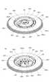
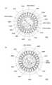
LEDモジュール203は、複数個のLED素子2031と、当該複数個のLED素子2031が実装されるLED基板2033とを有する。ここでの複数個のLED素子2031としては調色点灯するために複数種類の発光色の異なるものが用いられる。ここでのLEDモジュール203は3個あり、3個のLEDモジュール203はベース部材202の中央の貫通孔(図7の(b)及び図9には現れていない。)を囲んで環状に配されている。3個のLED基板2033は図示しない電気ケーブルにより端子2033a同士が接続されている。各LED基板2033は「へ」字状をし、LED素子2031がLED基板2033の長手方向に沿って1列に実装されている。これにより、複数個のLED素子2031が全体として円環状又は6角環状に配される。
(2) LED module This will be described mainly with reference to FIG. 7B and FIG.
TheLED module 203 has a plurality ofLED elements 2031 and anLED substrate 2033 on which the plurality ofLED elements 2031 are mounted. As the plurality ofLED elements 2031 here, a plurality of types having different emission colors are used for toning and lighting. Here, there are three LEDmodules 203, and the threeLED modules 203 are arranged in an annular shape around the central through hole of the base member 202 (not shown in FIG. 7B and FIG. 9). ing. Theterminals 2033a of the threeLED boards 2033 are connected to each other by an electric cable (not shown). EachLED board 2033 has a "he" shape, andLED elements 2031 are mounted in a row along the longitudinal direction of theLED board 2033. As a result, the plurality ofLED elements 2031 are arranged in an annular shape or a hexagonal annular shape as a whole.

3個のLED基板2033の内、少なくとも1つのLED基板2033Aは、金属ピン2045a用の貫通孔2033bを有し、図10に示すように、当該貫通孔2033bに対応して金属バネ片2035がLED基板2033Aに設けられている。なお、貫通孔2033bは金属バネ片2035のため図には現れていないが、他の貫通孔と区別するために「2033b」を付ける。
金属バネ片2035は、LED基板2033Aの貫通孔2033bを塞ぎ且つ金属ピン2045aの貫通孔2033bの通過に伴って弾性変形する。金属バネ片2035はLED基板2033Aの配線パターン(図示省略)と接続されている。
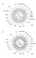
金属バネ片2035は、図10に示すように、矩形状の薄い金属板を湾曲させてなる。金属バネ片2035は、金属板の長手方向の中央に金属ピン2045a用の貫通孔2035aを有し、貫通孔2035aの両側に「く」字状に湾曲する「く」字状部2035bを有する。貫通孔2035aはLED基板2033Aの貫通孔2033bに対応して設けられている。「く」字状部2035bは、「く」字の屈曲部分が内側(貫通孔2035a上)に位置している。ここでの金属ピン2045aは9本ある。金属ピン2045aは、調光、調色、センサー及び常夜灯用である。
Of the threeLED substrates 2033, at least oneLED substrate 2033A has a through hole 2033b for themetal pin 2045a, and as shown in FIG. 10, themetal spring piece 2035 corresponds to the through hole 2033b and has an LED. It is provided on thesubstrate 2033A. The through hole 2033b is not shown in the figure because it is ametal spring piece 2035, but "2033b" is added to distinguish it from other through holes.
Themetal spring piece 2035 closes the through hole 2033b of theLED substrate 2033A and elastically deforms as themetal pin 2045a passes through the through hole 2033b. Themetal spring piece 2035 is connected to a wiring pattern (not shown) of theLED substrate 2033A.
As shown in FIG. 10, themetal spring piece 2035 is formed by bending a thin rectangular metal plate. Themetal spring piece 2035 has a throughhole 2035a for themetal pin 2045a in the center in the longitudinal direction of the metal plate, and has "dogleg" shapedportions 2035b curved in a "dogleg" shape on both sides of the throughhole 2035a. The throughhole 2035a is provided corresponding to the through hole 2033b of theLED substrate 2033A. In the "K" -shapedportion 2035b, the bent portion of the "K" shape is located inside (on the throughhole 2035a). There are ninemetal pins 2045a here. Themetal pin 2045a is for dimming, toning, sensor and nightlight.

(3)電源回路ユニット
主に図8の(b)及び図9の(a)を用いて説明する。
電源回路ユニット204は、LED素子2031に供給する電力を交流電力から生成するための電力変換回路や、調光点灯するための調光回路や、調色点灯するための調色回路等を含む。電源回路ユニット204は、複数個の回路部品2041と、回路部品2041が実装される回路基板2043と、LEDモジュール203と電気的に接続するための接続部2045とから構成される。なお、言うまでもなく、回路部品は上記回路を構成する電子部品であり、図8の(b)及び図9の(a)には便宜上1個の回路部品2041だけが記載されている。
回路基板2043は、上記回路を構成するように複数個の回路部品2041を接続するための配線パターン(図示省略)を有している。回路基板2043は、全体として外周縁が円弧状をする「L」字に近い形状をし、ベース部材202の表平坦部2021の貫通孔(引掛刃保持部材207のため図には表れていない。)に沿って配されている。回路基板2043は、図12に示すように、ベース部材202の表平坦部2021と間隔をおいた状態で、樹脂リベット2015により固定されている。これにより、ベース部材202を金属材料で構成した場合でも、電気安全性を向上させることができる。
回路基板2043は、引掛刃保持部材207にある一対の引掛刃2071に対して電気ケーブル2047を介して接続されている。
(3) Power supply circuit unit This will be described mainly using FIG. 8B and FIG. 9A.
The powersupply circuit unit 204 includes a power conversion circuit for generating electric power supplied to theLED element 2031 from AC power, a dimming circuit for dimming lighting, a toning circuit for dimming lighting, and the like. The powersupply circuit unit 204 includes a plurality ofcircuit components 2041, acircuit board 2043 on which thecircuit components 2041 are mounted, and aconnection portion 2045 for electrically connecting to theLED module 203. Needless to say, the circuit component is an electronic component constituting the circuit, and only onecircuit component 2041 is described in FIG. 8B and FIG. 9A for convenience.
Thecircuit board 2043 has a wiring pattern (not shown) for connecting a plurality ofcircuit components 2041 so as to form the above circuit. Thecircuit board 2043 has a shape close to an “L” shape whose outer peripheral edge is arcuate as a whole, and is not shown in the figure because of the through hole (the hooking blade holding member 207) of the frontflat portion 2021 of the base member 202. ) Is arranged. As shown in FIG. 12, thecircuit board 2043 is fixed by theresin rivet 2015 in a state of being spaced from the surfaceflat portion 2021 of thebase member 202. Thereby, even when thebase member 202 is made of a metal material, the electrical safety can be improved.
Thecircuit board 2043 is connected to the pair ofhook blades 2071 on the hookblade holding member 207 via anelectric cable 2047.

接続部2045について図11を用いて説明する。
接続部2045は、LED基板2033側に延出する9本の金属ピン2045aと、9本の金属ピン2045aを支持する支持体2045bとを有している。9本の金属ピン2045aは間隔をおいて回路基板2043に対して立設状態で支持体2045bにより支持されている。こここでの9本の金属ピン2054aは、一列状に配されている。なお、金属ピン2054aは、回路基板2043とLED基板2033とが表裏方向に重なる部分に設けられている。なお、ベース部材202の表平坦部2021は、9本の金属ピン2054aが挿通する1つの貫通孔を有している。
Theconnection portion 2045 will be described with reference to FIG.
Theconnection portion 2045 has ninemetal pins 2045a extending toward theLED substrate 2033 and asupport 2045b for supporting the ninemetal pins 2045a. The ninemetal pins 2045a are supported by thesupport 2045b in an upright position with respect to thecircuit board 2043 at intervals. The nine metal pins 2054a here are arranged in a row. The metal pin 2054a is provided at a portion where thecircuit board 2043 and theLED board 2033 overlap each other in the front-back direction. Theflat surface portion 2021 of thebase member 202 has one through hole through which nine metal pins 2054a are inserted.

(4)外カバー
図6から図8を用いて説明する。
外カバー205は、ここでは、ベース部材202側に取り付けられるフレーム2051と、フレーム2051に取り付けられるドーム状の透光性カバー2053とを有する。
フレーム2051は中央に貫通孔を有する環状をし、貫通孔にベース部材202の裏側部分が嵌る。ここでの環状は円環状である。フレーム2051は、円環部2051aと、円環部2051aの内周縁に設けられ且つ裏側が開口する内周溝部2051bと、外周縁から表側に段付き筒状に延出する筒状部2051cとを有している。
フレーム2051は、ベース部材202の外鍔部2029が内周溝部2051bに嵌った状態で、図7の(a)に示すように、内周溝部2051bの内側に設けられている係合片2051dがベース部材202側の係合溝2067に係合することで、ベース部材202側に取り外し可能に取り付けられる。なお、係合溝2067は、内カバー206の外周縁に設けられたフレーム装着部2065とベース部材202の裏平坦部2025との間に形成されている。
筒状部2051cの内周面には、図7に示すように、透光性カバー2053の係合凹部(図示省略)に係合する係合凸部2051eが周方向に間隔をおいて設けられ、当該係合凸部2051eが係合凹部に係合して透光性カバー2053がフレーム2051に取り付けられる。
(4) Outer cover This will be described with reference to FIGS. 6 to 8.
Theouter cover 205 has, here, aframe 2051 attached to thebase member 202 side and a dome-shapedtranslucent cover 2053 attached to theframe 2051.
Theframe 2051 has an annular shape having a through hole in the center, and the back side portion of thebase member 202 fits into the through hole. The ring here is a ring. Theframe 2051 includes anannular portion 2051a, an innerperipheral groove portion 2051b provided on the inner peripheral edge of theannular portion 2051a and an opening on the back side, and atubular portion 2051c extending from the outer peripheral edge to the front side in a stepped tubular shape. Have.
In theframe 2051, in a state where theouter flange portion 2029 of thebase member 202 is fitted in the innerperipheral groove portion 2051b, as shown in FIG. 7A, the engagingpiece 2051d provided inside the innerperipheral groove portion 2051b is provided. By engaging with theengagement groove 2067 on thebase member 202 side, it can be detachably attached to thebase member 202 side. The engaginggroove 2067 is formed between theframe mounting portion 2065 provided on the outer peripheral edge of theinner cover 206 and the backflat portion 2025 of thebase member 202.
As shown in FIG. 7, engagingconvex portions 2051e that engage with the engaging concave portions (not shown) of thetranslucent cover 2053 are provided on the inner peripheral surface of thetubular portion 2051c at intervals in the circumferential direction. , The engagingconvex portion 2051e engages with the engaging concave portion, and thetranslucent cover 2053 is attached to theframe 2051.

(5)内カバー
図7の(a)を用いて説明する。
内カバー206は、LEDモジュール203に近接した状態で、LEDモジュール203を覆う。これにより、例えば透光性カバー2053を外した状態で照明装置201を設置面の引掛けシーリング等に取り付ける際に、使用者がLED素子2031に触れるのを防止できる。
内カバー206は、ドーム状に表側に膨出する膨出部2061と、膨出部2061の周縁から裏平坦部2025と平行に延伸する環状部2063と、フレーム2051を取り付けるためのフレーム装着部2065とを有している。環状部2063は、周方向に間隔をおいて欠けた部分を有し、この欠けた部分に対応してフレーム装着部2065が設けられている。フレーム装着部2065は、環状部2063と同様に外方へ延伸するが、延伸する位置が環状部2063よりも表側にある。これにより、フレーム装着部2065の延伸部分とベース部材202の裏平坦部2025との間に係合溝2067が形成される。この係合溝2067にはフレーム2051の係合片2051dが係合する。なお、図7では、フレーム2051の係合片2051dが見えるように、係合溝2067に係合する前の状態を示している。
内カバー206は、2個のカバー体206A,206Bにより構成されている。2つのカバー体206A,206Bはねじ体によりベース部材202に固定されている。
(5) Inner cover This will be described with reference to FIG. 7 (a).
Theinner cover 206 covers theLED module 203 in a state close to theLED module 203. This makes it possible to prevent the user from touching theLED element 2031 when, for example, thelighting device 201 is attached to a hook ceiling or the like on the installation surface with thetranslucent cover 2053 removed.
Theinner cover 206 has a dome-shaped bulgingportion 2061 that bulges to the front side, anannular portion 2063 that extends from the peripheral edge of the bulgingportion 2061 in parallel with the backflat portion 2025, and aframe mounting portion 2065 for mounting theframe 2051. And have. Theannular portion 2063 has a chipped portion at intervals in the circumferential direction, and aframe mounting portion 2065 is provided corresponding to the chipped portion. Theframe mounting portion 2065 extends outward in the same manner as theannular portion 2063, but the extending position is on the front side of theannular portion 2063. As a result, an engaginggroove 2067 is formed between the extended portion of theframe mounting portion 2065 and the backflat portion 2025 of thebase member 202. The engagingpiece 2051d of theframe 2051 engages with the engaginggroove 2067. Note that FIG. 7 shows a state before engaging with the engaginggroove 2067 so that the engagingpiece 2051d of theframe 2051 can be seen.
Theinner cover 206 is composed of twocover bodies 206A and 206B. The twocover bodies 206A and 206B are fixed to thebase member 202 by a screw body.

(6)引掛刃保持部材
主に図7及び図8を用いて説明する。
引掛刃保持部材207は設置面の引掛けシーリング等に取り付けられる一対の引掛刃2071,2071を保持する。引掛刃保持部材207は、ベース部材202の貫通孔に表側から挿入され且つ表側に開口が位置する有底筒状部2073(図8参照)と、有底筒状部2073の開口側端縁から外方側に延伸し且つベース部材202の貫通孔の周辺部に当接する平坦部2075(図7の(b)参照)と、有底筒状部2073の底部分から表側へ中空状に突出し且つ内部空間に引掛刃2071,2071が設けられている突出部2077とを有している。引掛刃保持部材207は透明性の高い樹脂材料により構成されている。突出部2077は、照明装置201を取り付ける際に、使用者が把持するのに利用される。
(6) Hooking blade holding member This will be described mainly with reference to FIGS. 7 and 8.
The hookblade holding member 207 holds a pair ofhook blades 2071 and 2071 attached to a hook ceiling or the like on the installation surface. The hookingblade holding member 207 is inserted from the front side into the through hole of thebase member 202 and has an opening located on the front side from the bottomed tubular portion 2073 (see FIG. 8) and the bottomedtubular portion 2073 from the opening side edge. A flat portion 2075 (see (b) in FIG. 7) that extends outward and abuts on the peripheral portion of the through hole of thebase member 202, and a hollow protrusion from the bottom portion of the bottomedtubular portion 2073 to the front side and inside. It has a protrudingportion 2077 provided with hookingblades 2071 and 2071 in the space. The hookingblade holding member 207 is made of a highly transparent resin material. Theprotrusion 2077 is used by the user to grip thelighting device 201 when it is attached.

(7)裏カバー
主に図8の(a)及び図11を用いて説明する。
裏カバー208は、ベース部材202の内筒部2023の裏側を引掛刃保持部材207の有底筒状部2073の底部分を除いて扇状に覆う。裏カバー208は有底筒状部2073の底部に対応した開口を有する板部2081と、板部2081からベース部材202の内筒部2023を通って表側に延伸して表平坦部2021に当接する半筒状部2083(図11参照)を有している。
(7) Back cover This will be described mainly with reference to FIG. 8A and FIG.
Theback cover 208 covers the back side of theinner cylinder portion 2023 of thebase member 202 in a fan shape except for the bottom portion of the bottomedtubular portion 2073 of the hookingblade holding member 207. Theback cover 208 extends from theplate portion 2081 having an opening corresponding to the bottom of the bottomedtubular portion 2073 to the front side through theinner cylinder portion 2023 of thebase member 202 and abuts on the frontflat portion 2021. It has a semi-cylindrical portion 2083 (see FIG. 11).

<第3の実施形態>
1.全体構成
本実施形態に係る照明装置4001の概要について主に図13及び図14を用いて説明する。
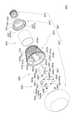
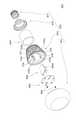
照明装置4001はLEDモジュール4003と電源回路ユニット4005とを外囲器4007の内部に備える。照明装置4001は、外囲器4007の一部を構成する口金4077から商用電源である交流電力を受電して、電源回路ユニット4005で変換された直流電力によりLED素子4031を発光(点灯)させる。
ここでの外囲器4007は、透光性カバー4071、筒体4073、口金保持体4075及び口金4077の4個の部材から構成されている。LEDモジュール4003は透光性カバー4071側に位置し、電源回路ユニット4005は口金4077側に位置している。
<Third embodiment>
1. 1. Overall Configuration The outline of thelighting device 4001 according to the present embodiment will be described mainly with reference to FIGS. 13 and 14.
Thelighting device 4001 includes anLED module 4003 and a powersupply circuit unit 4005 inside theenclosure 4007. Thelighting device 4001 receives AC power, which is a commercial power source, from thebase 4077 constituting a part of theenclosure 4007, and emits (lights) theLED element 4031 by the DC power converted by the powersupply circuit unit 4005.
Theouter enclosure 4007 here is composed of four members: atranslucent cover 4071, atubular body 4073, abase holder 4075, and abase 4077. TheLED module 4003 is located on thetranslucent cover 4071 side, and the powersupply circuit unit 4005 is located on thebase 4077 side.

2.各部構成
(1)LEDモジュール
図14を用いて説明する。
LEDモジュール4003は、1個又は複数個のLED素子4031と、LED素子4031が実装されるLED基板4033と、電源回路ユニット4005と接続するための接続部4035とを有する。
LED素子4031はここでは6個実装されている。LED基板4033は円板状をし、6個のLED素子4031はLED基板4033の周縁部に近い部分に周方向に等間隔をおいて環状(例えば円環状である。)に配されている。LED基板4033は、LEDモジュール4003を筒体4073に固定するための貫通孔4033aを複数個(ここでは2個である。)有している。
ここでの接続部4035はLED素子4031が配されている円環の内側部分に設けられている。接続部4035はLED素子4031に電力を供給する配線パターンと電気的に接続されている。接続部4035は、LED基板4033に設けられた貫通孔4035aと、LED基板4033に設けられた金属バネ片4035bとから構成されている。
2. 2. Each part configuration (1) LED module This will be described with reference to FIG.
TheLED module 4003 has one or a plurality ofLED elements 4031, anLED substrate 4033 on which theLED element 4031 is mounted, and aconnection portion 4035 for connecting to the powersupply circuit unit 4005.
SixLED elements 4031 are mounted here. TheLED substrate 4033 has a disk shape, and the sixLED elements 4031 are arranged in an annular shape (for example, an annular shape) at equal intervals in the circumferential direction in a portion close to the peripheral edge portion of theLED substrate 4033. TheLED substrate 4033 has a plurality of throughholes 4033a (here, two) for fixing theLED module 4003 to thetubular body 4073.
Theconnection portion 4035 here is provided in the inner portion of the ring in which theLED element 4031 is arranged. Theconnection portion 4035 is electrically connected to a wiring pattern that supplies electric power to theLED element 4031. Theconnection portion 4035 is composed of a throughhole 4035a provided in theLED board 4033 and ametal spring piece 4035b provided in theLED board 4033.

金属バネ片4035bは、金属ピン4055aにおける貫通孔4035aから延出する延出部分と接触するように貫通孔4035aの周辺に設けられている。金属バネ片4035bは、ここでは各貫通孔4035aに対して設けられている。
金属バネ片4035bは、LED基板4033の貫通孔4035aを塞ぎ、金属ピン4055aの通過に伴って弾性変形する。金属バネ片4035bは一対あり、金属バネ片4035bの形状はかぎ状をしている。一対の金属バネ片4035b,4035bは、湾曲又は屈曲して部分が貫通孔4035a上に位置する状態で、貫通孔4035aを挟んで配されている。なお、金属バネ片4035bにおける湾曲又は屈曲している側と反対側の端部がLED基板4033に固定されている。
Themetal spring piece 4035b is provided around the throughhole 4035a so as to come into contact with the extending portion extending from the throughhole 4035a in themetal pin 4055a. Themetal spring piece 4035b is provided here for each throughhole 4035a.
Themetal spring piece 4035b closes the throughhole 4035a of theLED substrate 4033 and elastically deforms with the passage of themetal pin 4055a. There is a pair ofmetal spring pieces 4035b, and the shape of themetal spring pieces 4035b is hook-shaped. The pair ofmetal spring pieces 4035b, 4035b are arranged so as to sandwich the throughhole 4035a in a state where the portion is curved or bent and the portion is located on the throughhole 4035a. The end of themetal spring piece 4035b on the opposite side to the curved or bent side is fixed to theLED substrate 4033.

(2)電源回路ユニット
主に図14を用いて説明する。
電源回路ユニット4005は、LED素子4031に供給する電力を交流電力から生成するための電源回路を備える。電源回路ユニット4005は、複数個の回路部品4051と、回路部品4051が実装される回路基板4053と、LEDモジュール4003と接続するための接続部4055とから構成される。
(2) Power supply circuit unit This will be described mainly with reference to FIG.
The powersupply circuit unit 4005 includes a power supply circuit for generating electric power supplied to theLED element 4031 from AC power. The powersupply circuit unit 4005 includes a plurality ofcircuit components 4051, acircuit board 4053 on which thecircuit components 4051 are mounted, and aconnection portion 4055 for connecting to theLED module 4003.

回路部品4051は上記電源回路を構成する電子部品である。
回路基板4053は、上記電源回路を構成するように複数個の回路部品4051を接続するための配線パターンを有している。回路基板4053は、全体として矩形状をし、筒体4073の中心軸に沿って配される。ここでの回路基板4053は、筒体4073の中心軸と平行に配され、また、中心軸上に位置するように配されている。また、本実施形態とは異なるように回路基板が中心軸から偏倚して位置するように配されてもよい。
回路基板4053は一対の欠け部4053aを口金4077側に有している。ここでの欠け部4053aは矩形状をしている。換言すると、回路基板4053は一対の張出部4053bをLEDモジュール4003側に有している。張出部4053bは、筒体4073の内周面の溝4735aにLEDモジュール4003が存在する側から挿入されて、溝4735aと嵌合する。回路基板4053の張出部4053b及び溝4735aの長さは、回路基板4053とLEDモジュール4003を筒体4073に組み込んだ際に回路基板4053のLEDモジュール4003側の端縁がLEDモジュール4003のLED基板4033に近接又は当接するように、構成されている。また、回路基板4053の口金4077側の端縁が口金保持体4075の内部にまで及ばさせずに筒体4073内部に位置するように、構成されている。
Thecircuit component 4051 is an electronic component constituting the power supply circuit.
Thecircuit board 4053 has a wiring pattern for connecting a plurality ofcircuit components 4051 so as to form the power supply circuit. Thecircuit board 4053 has a rectangular shape as a whole and is arranged along the central axis of thetubular body 4073. Thecircuit board 4053 here is arranged parallel to the central axis of thetubular body 4073, and is arranged so as to be located on the central axis. Further, the circuit board may be arranged so as to be displaced from the central axis so as to be different from the present embodiment.
Thecircuit board 4053 has a pair of chippedportions 4053a on thebase 4077 side. The chippedportion 4053a here has a rectangular shape. In other words, thecircuit board 4053 has a pair of overhangingportions 4053b on theLED module 4003 side. The overhangingportion 4053b is inserted into thegroove 4735a on the inner peripheral surface of thetubular body 4073 from the side where theLED module 4003 exists, and fits into thegroove 4735a. The length of the overhangingportion 4053b and thegroove 4735a of thecircuit board 4053 is such that when thecircuit board 4053 and theLED module 4003 are incorporated into thecylinder 4073, the edge of thecircuit board 4053 on theLED module 4003 side is the LED board of theLED module 4003. It is configured to be in close proximity to or in contact with the 4033. Further, the edge of thecircuit board 4053 on thebase 4077 side is configured to be located inside thecylinder 4073 without extending to the inside of thebase holder 4075.

接続部4055は、回路基板4053におけるLEDモジュール4003側の端部に設けられ、回路基板4053の配線パターンと電気的に接続されている。接続部4055は金属ピン4055aにより構成されている。金属ピン4055aは、先端側が回路基板4053からLEDモジュール4003側に延出する状態で、回路基板4053に固定されている。金属ピン4055aは、2本あり、間隔をおいて設けられている。 Theconnection portion 4055 is provided at the end of thecircuit board 4053 on theLED module 4003 side, and is electrically connected to the wiring pattern of thecircuit board 4053. Theconnection portion 4055 is composed of ametal pin 4055a. Themetal pin 4055a is fixed to thecircuit board 4053 with the tip end extending from thecircuit board 4053 to theLED module 4003 side. There are twometal pins 4055a, which are provided at intervals.

(3)外囲器
(3-1)透光性カバー
主に図14及び図15を用いて説明する。
透光性カバー4071は、LEDモジュール4003を覆い、LEDモジュール4003から発せられた光を透過させて出射する。透光性カバー4071は、例えば中空楕円球の短軸側端部を平面で切断したような形状をしている。透光性カバー4071は取付部である段差4071aを開口端部に有している。ここでの段差4071aは開口端面から内周側部分が突出して構成される。換言すると、段差4071aは透光性カバー4071の開口端部の外周側が凹入する。
透光性カバー4071は、段差4071aのある部分が筒体4073のLEDモジュール4003側の開口端部の段差4738aに嵌合する状態で、例えば接着剤等を利用して筒体4073に取り付けられている。透光性カバー4071は例えば透光性を有する樹脂材料から構成されている。透光性カバー4071は、必要に応じて、樹脂材料に拡散粒子が混入されてもよいし、内周面や外周面に拡散処理が施されてもよい。
(3) Encloser (3-1) Translucent cover This will be described mainly with reference to FIGS. 14 and 15.
Thetranslucent cover 4071 covers theLED module 4003 and transmits and emits the light emitted from theLED module 4003. Thetranslucent cover 4071 has a shape, for example, a hollow ellipsoidal sphere having a short-axis side end cut in a plane. Thetranslucent cover 4071 has astep 4071a, which is a mounting portion, at the open end. Thestep 4071a here is configured such that the inner peripheral side portion protrudes from the opening end surface. In other words, thestep 4071a is recessed on the outer peripheral side of the open end portion of thetranslucent cover 4071.
Thetranslucent cover 4071 is attached to thecylinder 4073 using, for example, an adhesive or the like in a state where the portion having thestep 4071a is fitted to thestep 4738a at the opening end on theLED module 4003 side of thecylinder 4073. There is. Thetranslucent cover 4071 is made of, for example, a translucent resin material. If necessary, thetranslucent cover 4071 may have diffusion particles mixed in the resin material, or may be subjected to diffusion treatment on the inner peripheral surface and the outer peripheral surface.

(3-2)筒体
図14から図17、特に図17を用いて説明する。
筒体4073は主にLEDモジュール4003及び電源回路ユニット4005を装着する機能を有する。ここでの筒体4073は、内部に電源回路ユニット4005を収容し、LEDモジュール4003を装着する機能を有する。なお、電源回路ユニット4005はLEDモジュール4003を利用して筒体4073に装着される。
(3-2) Cylindrical body FIGS. 14 to 17, especially FIG. 17, will be described.
Thetubular body 4073 mainly has a function of mounting theLED module 4003 and the powersupply circuit unit 4005. Thetubular body 4073 here has a function of accommodating the powersupply circuit unit 4005 inside and mounting theLED module 4003. The powersupply circuit unit 4005 is mounted on thetubular body 4073 by using theLED module 4003.

筒体4073の内周径はLEDモジュール4003側の開口端部を除いて略一定である。筒体4073の外周径は中心軸上を口金4077側の開口端部からLEDモジュール4003側の開口端部に移るにしたがって大きくなり、筒体4073の全体の外観形状はテーパー状をしている。
筒体4073は周方向に間隔をおいて設けられた溝4731を外周面に複数本有し、周方向に隣接する溝4731間が放熱用のフィン部4732となっている。このような構成により、筒体4073は、LEDモジュール4003及び電源回路ユニット4005から発せられた熱を放出するヒートシンクの機能を有する。なお、ここでの溝4731は、中心軸に向かって凹入し、中心軸と平行に延伸している。図14及び図17において、溝4731はフィン部4732と区別するために引き出し線の先端を矢印にしている。
The inner circumference of thecylinder 4073 is substantially constant except for the opening end on theLED module 4003 side. The outer peripheral diameter of thecylinder 4073 increases as it moves from the opening end on thebase 4077 side to the opening end on theLED module 4003 side on the central axis, and the overall external shape of thecylinder 4073 is tapered.
Thetubular body 4073 has a plurality ofgrooves 4731 provided at intervals in the circumferential direction on the outer peripheral surface, and the space between thegrooves 4731 adjacent to each other in the circumferential direction is afin portion 4732 for heat dissipation. With such a configuration, thetubular body 4073 has a function of a heat sink that discharges heat generated from theLED module 4003 and the powersupply circuit unit 4005. Thegroove 4731 here is recessed toward the central axis and extends in parallel with the central axis. In FIGS. 14 and 17, thegroove 4731 has an arrow at the tip of the lead wire to distinguish it from thefin portion 4732.

筒体4073は、内径及び外径が一定のストレート筒部4733と、ストレート筒部4733のLEDモジュール4003側の端部から中心軸方向をストレート筒部4733から離れるにしたがって内径及び外径が大きくなるテーパー筒部4734と、ストレート筒部4733及びテーパー筒部4734の外周に設けられたフィン部4732と、電源回路ユニット4005を装着するための装着部4735と、LEDモジュール4003を固定するための固定部4736とを有している。
筒体4073は、図14から図17に示すように、LEDモジュール4003側の端部を除いた内周面、つまり、ストレート筒部4733の内周面に密着する金属筒4074を備える。
The inner diameter and outer diameter of thecylinder 4073 increase as the distance from thestraight cylinder 4733 having a constant inner diameter and outer diameter and the end of thestraight cylinder 4733 on theLED module 4003 side in the central axis direction from thestraight cylinder 4733. Ataper cylinder portion 4734, afin portion 4732 provided on the outer periphery of thestraight cylinder portion 4733 and thetaper cylinder portion 4734, a mountingportion 4735 for mounting the powersupply circuit unit 4005, and a fixing portion for fixing theLED module 4003. It has 4736 and.
As shown in FIGS. 14 to 17, thecylinder body 4073 includes ametal cylinder 4074 that is in close contact with the inner peripheral surface excluding the end portion on theLED module 4003 side, that is, the inner peripheral surface of thestraight cylinder portion 4733.

筒体4073は、テーパー筒部4734におけるストレート筒部4733側の端部から延伸して口金4077側の端部に向かう「L」字状のリブ4737を周方向に間隔をおいて複数個(ここでは4本である。)有している。換言すると、筒体4073は、ストレート筒部4733の内周面に対して径方向内側に間隔をおいてストレート筒部4733の内周面と平行に延伸する延伸部4737aと、延伸部4737aにおけるテーパー筒部4734側の端部とテーパー筒部4734とを連結する連結部4737bとを有するリブ4737を備える。連結部4737bは筒体4073の中心軸と直交する方向に延伸し、延伸部4737aは中心軸と平行に延伸している。
金属筒4074は、リブ4737の延伸部4737aとストレート筒部4733の内周面との間に組み込まれている。金属筒4074が組み込まれた状態で説明すると、リブ4737は、テーパー筒部4734におけるストレート筒部4733側の端部から中心軸に向かって延伸(連結部4737bである。)し、金属筒4074の内周面を超えたところで口金4077側の端部に向かって延伸する(延伸部4737aである。)。換言すると、リブ4737は金属筒4074の端面と内周面に沿って設けられている。
Thetubular body 4073 has a plurality of "L" -shapedribs 4737 extending from the end portion of the taperedtubular portion 4734 on thestraight tubular portion 4733 side toward the end portion on thebase 4077 side at intervals in the circumferential direction (here). Then there are four.) I have. In other words, thetubular body 4073 has a stretchedportion 4737a extending in parallel with the inner peripheral surface of thestraight tubular portion 4733 at intervals in the radial direction with respect to the inner peripheral surface of thestraight tubular portion 4733, and a taper in the stretchedportion 4737a. Arib 4737 having a connectingportion 4737b for connecting an end portion on thetubular portion 4734 side and atapered tubular portion 4734 is provided. The connectingportion 4737b is stretched in a direction orthogonal to the central axis of thetubular body 4073, and the stretchedportion 4737a is stretched in parallel with the central axis.
Themetal cylinder 4074 is incorporated between theextended portion 4737a of therib 4737 and the inner peripheral surface of thestraight cylinder portion 4733. Explaining in a state where themetal cylinder 4074 is incorporated, therib 4737 extends from the end portion of the taperedcylinder portion 4734 on thestraight cylinder portion 4733 side toward the central axis (it is a connectingportion 4737b), and themetal cylinder 4074 When it exceeds the inner peripheral surface, it is stretched toward the end portion on thebase 4077 side (stretchedportion 4737a). In other words, therib 4737 is provided along the end surface and the inner peripheral surface of themetal cylinder 4074.

装着部4735及び固定部4736はリブ4737に設けられている。ここでの装着部4735は筒体4073の中心軸を挟んで対向する一対のリブ4737に設けられ、固定部4736は中心軸を挟み且つ装着部4735が設けられていない一対のリブ4737に設けられている。
装着部4735は、図14及び図17に示すように、連結部4737bから延伸部4737aに跨って設けられた溝4735aにより構成される。溝4735aは延伸部4737aにおける口金4077側の端部の途中まで存在し、溝4735aの長さは回路基板4053の張出部4053bの長さに略等しい。固定部4736は、図14及び図17に示すように、連結部4737bから延伸部4737aに跨って設けられたねじ穴4736aにより構成される。なお、4つの連結部4737bのテーパー筒部4734側の端面は、口金4077側の端部を基準にすると、同じ高さである。
The mountingportion 4735 and the fixingportion 4736 are provided on therib 4737. The mountingportion 4735 here is provided on a pair ofribs 4737 facing each other across the central axis of thetubular body 4073, and the fixingportion 4736 is provided on a pair ofribs 4737 that sandwich the central shaft and do not have a mountingportion 4735. ing.
As shown in FIGS. 14 and 17, the mountingportion 4735 is composed of agroove 4735a provided so as to extend from the connectingportion 4737b to the extendingportion 4737a. Thegroove 4735a exists halfway through the end portion of theextended portion 4737a on thebase 4077 side, and the length of thegroove 4735a is substantially equal to the length of the overhangingportion 4053b of thecircuit board 4053. As shown in FIGS. 14 and 17, the fixingportion 4736 is composed of ascrew hole 4736a provided so as to extend from the connectingportion 4737b to the extendingportion 4737a. The end faces of the four connectingportions 4737b on the taperedcylinder portion 4734 side have the same height with respect to the end portion on thebase 4077 side.

筒体4073は、図17に示すように、テーパー筒部4734における透光性カバー4071側の端部に、透光性カバー4071を取り付けるためのカバー取付部4738を有している。カバー取付部は4738は、内周側から凹入する段差4738aにより構成されている。
筒体4073は、図17に示すように、口金4077を固定するための口金固定部4739を口金4077側の端部に有している。ここでは、口金4077は口金保持体4075を介して固定されるため、正確に言うと、口金固定部4739は口金保持体4075を固定するためのものである。口金固定部4739はストレート筒部4733の口金4077側の端部に設けられた段差4739aと、段差4739aを構成する中心軸と平行な周面に設けられた凹みにより構成される。段差4739aは外周側が凹入している。ここで、周面に設けられた凹みは周方向に延伸する周溝4739bにより構成されている。
筒体4073は樹脂材料により構成されている。金属筒4074は筒体4073の成形時に一体で成形するインサート成形により筒体に配されてもよいし、筒体4073の成形後に金属筒4074を挿入してもよい。
As shown in FIG. 17, thetubular body 4073 has acover mounting portion 4738 for mounting thetranslucent cover 4071 at the end portion of the taperedtubular portion 4734 on thetranslucent cover 4071 side. Thecover mounting portion 4738 is composed of astep 4738a recessed from the inner peripheral side.
As shown in FIG. 17, thetubular body 4073 has abase fixing portion 4739 for fixing thebase 4077 at the end on thebase 4077 side. Here, since thebase 4077 is fixed via thebase holder 4075, to be precise, thebase fixing portion 4739 is for fixing thebase holder 4075. Thebase fixing portion 4739 is composed of astep 4739a provided at the end of thestraight cylinder portion 4733 on thebase 4077 side and a recess provided on the peripheral surface parallel to the central axis constituting thebase 4739a. The outer peripheral side of thestep 4739a is recessed. Here, the recess provided on the peripheral surface is composed of aperipheral groove 4739b extending in the circumferential direction.
Thecylinder 4073 is made of a resin material. Themetal cylinder 4074 may be arranged on the cylinder by insert molding, which is integrally molded at the time of molding thecylinder 4073, or themetal cylinder 4074 may be inserted after thecylinder 4073 is molded.

(3-3)口金保持体
図14及び図15を用いて説明する。
口金保持体4075は筒状をしている。口金保持体4075は、筒体4073側に位置する大径筒部4751と、口金4077側に位置する小径筒部4753と、大径筒部4751と小径筒部4753とを接続するテーパー筒部4755とを有する。大径筒部4751は小径筒部4753よりも内径及び外径が大きい。テーパー筒部4755は小径筒部4753に向かって直線状に縮径する。
口金保持体4075は、筒体4073に固定される筒体側固定部4757と、口金4077が固定される口金側固定部とを有している。筒体側固定部4757は筒体4073の口金固定部4739の凹みである周溝4739bに嵌る凸部4757aにより構成されている。凸部4757aは大径筒部4751の端部内周面であって周方向に間隔をおいて複数個(ここでは4個である。)設けられている。口金側固定部は小径筒部4753の外周面で構成され、例えば接着剤を介して口金4077が口金側固定部で固定される。
(3-3) Mouthpiece holder A description will be given with reference to FIGS. 14 and 15.
Thebase holder 4075 has a cylindrical shape. Thebase holder 4075 is atapered cylinder portion 4755 that connects a largediameter cylinder portion 4751 located on thecylinder body 4073 side, a smalldiameter cylinder portion 4753 located on thebase 4077 side, and a largediameter cylinder portion 4751 and a smalldiameter cylinder portion 4753. And have. The largediameter cylinder portion 4751 has a larger inner diameter and outer diameter than the smalldiameter cylinder portion 4753. The taperedcylinder portion 4755 is linearly reduced in diameter toward the smalldiameter cylinder portion 4753.
Thebase holding body 4075 has a cylinderside fixing portion 4757 fixed to thecylinder 4073 and a base side fixing portion to which thebase 4077 is fixed. The cylinder-side fixing portion 4757 is composed of aconvex portion 4757a that fits into theperipheral groove 4739b, which is a recess of thebase fixing portion 4739 of thecylinder body 4073. A plurality ofconvex portions 4757a (here, four) are provided on the inner peripheral surface of the end portion of the large-diameter tubular portion 4751 at intervals in the circumferential direction. The base-side fixing portion is composed of the outer peripheral surface of the small-diameter cylinder portion 4753, and thebase 4077 is fixed by the base-side fixing portion, for example, via an adhesive.

(3-4)口金
図14及び図15を用いて説明する。
口金4077は、従来の電球に利用されていた口金と同じ構成であり、シェル部とアイレット部とを有し、アイレット部が絶縁部を介してシェル部に取り付けられている。
(3-4) Base The description will be made with reference to FIGS. 14 and 15.
Thebase 4077 has the same configuration as the base used for a conventional light bulb, has a shell portion and an eyelet portion, and the eyelet portion is attached to the shell portion via an insulating portion.

3.LED基板と電源回路ユニットとの接続
電源回路ユニット4005は一対の金属ピン4055aを回路基板4053におけるLEDモジュール4003側に端部に有し、当該金属ピン4055aがLEDモジュール4003のLED基板4033の貫通孔4035aを挿通する。金属ピン4055aの貫通孔4035aの通過に伴って、金属バネ片4035bが金属ピン4055aとの接触を維持した状態で弾性変形する。これにより、LED基板4033と回路基板4053とを電気的に確実に接続できる。
このように、LEDモジュール4003と電源回路ユニット4005の電気的接続は、金属ピン4055aをLED基板4033の貫通孔4035aに挿通させるだけでよく、容易に行うことができる。
3. 3. Connection between LED Board and Power Supply Circuit Unit The powersupply circuit unit 4005 has a pair ofmetal pins 4055a at the end of thecircuit board 4053 on theLED module 4003 side, and themetal pins 4055a are through holes of theLED board 4033 of theLED module 4003. 4035a is inserted. As themetal pin 4055a passes through the throughhole 4035a, themetal spring piece 4035b is elastically deformed while maintaining contact with themetal pin 4055a. As a result, theLED board 4033 and thecircuit board 4053 can be reliably and electrically connected.
As described above, the electrical connection between theLED module 4003 and the powersupply circuit unit 4005 can be easily performed by simply inserting themetal pin 4055a into the throughhole 4035a of theLED substrate 4033.

4.電源回路ユニットとLEDモジュールの固定
主に図14を用いて説明する。
電源回路ユニット4005の装着に際し、回路基板4053の欠け部4053aが存在する側を筒体4073のテーパー筒部4734側にして、回路基板4053の張出部4053bにおける欠け部4053a側の端縁が溝4735aの端に当接するまで、回路基板4053が筒体4073内に挿入される。
溝4735aに挿入された状態の回路基板4053の金属ピン4055aに対してLEDモジュール4003の貫通孔4035aが嵌るように、LED基板4033を筒体4073のリブ4737の連結部4737b上に載置する。この状態で、ねじ体4004のねじ部をLED基板4033の貫通孔4033aを挿通させて筒体4073のねじ穴4736aに螺合させる。これにより、電源回路ユニット4005が筒体4073内に収容され、LEDモジュール4003が筒体4073に固定される。それと同時に、電源回路ユニット4005とLEDモジュール4003との電気的接続も行われる。
4. Fixing the power supply circuit unit and the LED module This will be described mainly with reference to FIG.
When mounting the powersupply circuit unit 4005, the side where the chippedportion 4053a of thecircuit board 4053 exists is set to the taperedtubular portion 4734 side of thetubular body 4073, and the edge of the overhangingportion 4053b of thecircuit board 4053 on the chippedportion 4053a side is a groove. Thecircuit board 4053 is inserted into thecylinder 4073 until it abuts on the end of the 4735a.
TheLED board 4033 is placed on the connectingportion 4737b of therib 4737 of thecylinder 4073 so that the throughhole 4035a of theLED module 4003 fits into themetal pin 4055a of thecircuit board 4053 inserted in thegroove 4735a. In this state, the threaded portion of the threadedbody 4004 is screwed into the threadedhole 4736a of thetubular body 4073 by inserting the throughhole 4033a of theLED substrate 4033. As a result, the powersupply circuit unit 4005 is housed in thetubular body 4073, and theLED module 4003 is fixed to thetubular body 4073. At the same time, the powersupply circuit unit 4005 and theLED module 4003 are electrically connected.

LEDモジュール4003の装着は、LED基板4033が連結部4737bの端面に当接する状態で行えるため、当接部分を貫通するねじ体4004をしっかりと締結することができる。これにより、金属バネ片4035bの復元力によりねじ体4004が緩むようなことを防止できる。
電源回路ユニット4005は筒体4073のリブ4737の延伸部4737aに装着される。このため筒体4073内の金属筒4074と接触するおそれがなく、特別な絶縁対策を要しない。LEDモジュール4003は筒体4073のリブ4737の連結部4737bにおける透光性カバー4071側の面に当接する状態で固定される。このため筒体4073内の金属筒4074と接触するおそれがなく、特別な絶縁対策を要しない。
また、電源回路ユニット4005は一対のリブ4737(延伸部4737a)間に位置し、さらに張出部4053bが溝4735aに挿入されるため、一対のリブ4737(延伸部4737a)に対する回路基板4053の位置ズレを防止できる。これにより、例えば長期の使用により延伸部4737aが金属筒4074から離れようとしても回路基板4053より防止され、結果的に長期間にわたり電源回路ユニット4005と金属筒4074との絶縁性を確保できる。
筒体4073に回路基板4053が組み込まれた状態において、LED基板4033が回路基板4053の端縁に近接又は当接するように、LEDモジュール4003が筒体4073に固定される。このため、回路基板4053を固定するための新たな構成を要しない。
Since theLED module 4003 can be mounted in a state where theLED substrate 4033 is in contact with the end surface of the connectingportion 4737b, thescrew body 4004 penetrating the contact portion can be firmly fastened. This makes it possible to prevent thescrew body 4004 from loosening due to the restoring force of themetal spring piece 4035b.
The powersupply circuit unit 4005 is mounted on theextended portion 4737a of therib 4737 of thetubular body 4073. Therefore, there is no possibility of contact with themetal cylinder 4074 in thecylinder 4073, and no special insulation measures are required. TheLED module 4003 is fixed in a state of being in contact with the surface of thetubular body 4073 on thetranslucent cover 4071 side of the connectingportion 4737b of therib 4737. Therefore, there is no possibility of contact with themetal cylinder 4074 in thecylinder 4073, and no special insulation measures are required.
Further, since the powersupply circuit unit 4005 is located between the pair of ribs 4737 (stretchedportion 4737a) and the overhangingportion 4053b is inserted into thegroove 4735a, the position of thecircuit board 4053 with respect to the pair of ribs 4737 (stretchedportion 4737a). Misalignment can be prevented. As a result, for example, even if the stretchedportion 4737a tries to separate from themetal cylinder 4074 due to long-term use, it is prevented from thecircuit board 4053, and as a result, the insulation between the powersupply circuit unit 4005 and themetal cylinder 4074 can be ensured for a long period of time.
With thecircuit board 4053 incorporated in thecylinder 4073, theLED module 4003 is fixed to thecylinder 4073 so that theLED board 4033 is close to or abuts on the edge of thecircuit board 4053. Therefore, a new configuration for fixing thecircuit board 4053 is not required.

5.点灯時の放熱について
照明装置4001を点灯させた際、LEDモジュール4003及び電源回路ユニット4005から熱が発生する。この熱は金属筒4074を介して筒体4073のフィン部4732に伝達して放熱される。
金属筒4074はストレート筒部4733の内周側に配され、金属筒4074の内周面は4本のリブ4737が存在する部分を除く大部分が内部空間に面している。これにより金属筒4074に伝わる熱量を多くすることができる。
5. Heat dissipation during lighting When thelighting device 4001 is turned on, heat is generated from theLED module 4003 and the powersupply circuit unit 4005. This heat is transferred to thefin portion 4732 of thecylinder body 4073 via themetal cylinder 4074 and dissipated.
Themetal cylinder 4074 is arranged on the inner peripheral side of thestraight cylinder portion 4733, and most of the inner peripheral surface of themetal cylinder 4074 faces the internal space except for the portion where the fourribs 4737 exist. As a result, the amount of heat transferred to themetal cylinder 4074 can be increased.

<第4の実施形態>
1.概略
第4の実施形態について図18~図21を用いて説明する。
第4の実施形態に係る照明装置5001も、所謂、電球型ランプである。ここでは、第3の実施形態に係る照明装置4001の構成部品と同じ部品は同じ符号を利用し、その説明は省略する。なお、同じ構成部品は図面にのみ記載している場合もある。
照明装置5001は、図19に示すように、外囲器5007内にLEDモジュール4003と電源回路ユニット4005とを収容している。外囲器5007は、図18に示すように、透光性カバー4071、筒体5073、口金保持体4075及び口金4077から構成される、なお、筒体5073内には第3の実施形態と同様に金属筒4074が設けられている。
照明装置5001は第3の実施形態の照明装置4001と比較して筒体5073が異なる。このため、以下、筒体5073について説明する。
<Fourth Embodiment>
1. 1. Schematic The fourth embodiment will be described with reference to FIGS. 18 to 21.
Thelighting device 5001 according to the fourth embodiment is also a so-called light bulb type lamp. Here, the same reference numerals are used for the same components as the components of thelighting device 4001 according to the third embodiment, and the description thereof will be omitted. The same components may be described only in the drawings.
As shown in FIG. 19, thelighting device 5001 houses theLED module 4003 and the powersupply circuit unit 4005 in theenclosure 5007. As shown in FIG. 18, theouter enclosure 5007 is composed of atranslucent cover 4071, acylinder 5073, abase holder 4075, and abase 4077, and the inside of thecylinder 5073 is the same as in the third embodiment. Is provided with ametal cylinder 4074.
The illuminatingdevice 5001 has a differenttubular body 5073 as compared with the illuminatingdevice 4001 of the third embodiment. Therefore, thetubular body 5073 will be described below.

2.筒体
筒体5073の内周径はLEDモジュール4003側の開口端部を除いて略一定である。筒体4073の外周径は中心軸上を口金4077側の開口端部からLEDモジュール4003側の開口端部に移るにしたがって大きくなり、筒体5073の全体の外観形状はテーパー状をしている。
筒体5073は、図19及び図21に示すように、内径及び外径が一定のストレート筒部5731と、ストレート筒部5731のLEDモジュール4003側の端部から中心軸方向をストレート筒部5731から離れるにしたがって内径及び外径が大きくなるテーパー筒部5732と、ストレート筒部5731における口金4077側の端部から中心軸方向に突出する内鍔部5733と、ストレート筒部5731及びテーパー筒部5732の外周に設けられたフィン部5734と、電源回路ユニット4005を装着するための装着部5735と、LEDモジュール4003を固定するための固定部5736とを有している。
2. 2. Cylindrical body The inner peripheral diameter of thetubular body 5073 is substantially constant except for the opening end on theLED module 4003 side. The outer peripheral diameter of thecylinder 4073 increases as it moves from the opening end on thebase 4077 side to the opening end on theLED module 4003 side on the central axis, and the overall external shape of thecylinder 5073 is tapered.
As shown in FIGS. 19 and 21, thecylinder 5073 has astraight cylinder portion 5731 having a constant inner diameter and outer diameter, and astraight cylinder portion 5731 from the end portion of thestraight cylinder portion 5731 on theLED module 4003 side in the central axis direction from thestraight cylinder portion 5731. Atapered cylinder portion 5732 whose inner diameter and outer diameter increase as the distance increases, aninner flange portion 5733 protruding from the end of thestraight cylinder portion 5731 on thebase 4077 side in the central axis direction, and astraight cylinder portion 5731 and atapered cylinder portion 5732. It has afin portion 5734 provided on the outer periphery, a mountingportion 5735 for mounting the powersupply circuit unit 4005, and a fixingportion 5736 for fixing theLED module 4003.

テーパー筒部5732は、ストレート筒部5731の端面を残し、ストレート筒部5731の端部の外周面から延出するように設けられている。
フィン部5734は、第3の実施形態と同様に、周方向に間隔をおいて設けられた複数本の溝5737を利用して構成されている。なお、図18、図20及び図21において、溝5737はフィン部5734、ストレート筒部5731、テーパー筒部5732等と区別するために引き出し線の先端を矢印にしている。
筒体5073は、図18、図20及び図21に示すように、LEDモジュール4003側の端部を除いた内周面、つまり、ストレート筒部5731の内周面に密着する金属筒4074を内部に備える。ここでは、金属筒4074におけるテーパー筒部5732側の端面は露出している。
The taperedcylinder portion 5732 is provided so as to extend from the outer peripheral surface of the end portion of thestraight cylinder portion 5731, leaving the end surface of thestraight cylinder portion 5731.
Similar to the third embodiment, thefin portion 5734 is configured by utilizing a plurality ofgrooves 5737 provided at intervals in the circumferential direction. In FIGS. 18, 20, and 21, thegroove 5737 has an arrow at the tip of the lead wire in order to distinguish it from thefin portion 5734, thestraight tubular portion 5731, the taperedtubular portion 5732, and the like.
As shown in FIGS. 18, 20, and 21, thetubular body 5073 has an inner peripheral surface excluding the end on theLED module 4003 side, that is, ametal cylinder 4074 that is in close contact with the inner peripheral surface of thestraight tubular portion 5731. Prepare for. Here, the end face of themetal cylinder 4074 on the taperedcylinder portion 5732 side is exposed.

筒体5073は、図19に示すように、内鍔部5733からテーパー筒部5732に向かって延伸する延伸部5738を複数本有している。ここでの延伸部5738は4本あり、4本の延伸部5738が周方向に等間隔をおいて設けられている。換言すると、筒体5073は、ストレート筒部5731の内周面に対して径方向内側に間隔をおいてストレート筒部5731の内周面と平行に延伸する延伸部5738を備える。ここでの延伸部5738は中心軸と平行に延伸している。
金属筒4074は、延伸部5738とストレート筒部5731との間に組み込まれている。金属筒4074が組み込まれた状態で説明すると、延伸部5738は、図19に示すように、筒体4073の内鍔部5733から金属筒4074の内周面に沿って設けられている。
装着部5735及び固定部5736は延伸部5738に設けられている。ここでの装着部5735は、図21に示すように、筒体5073の中心軸を挟んで対向する一対の延伸部5738に設けられている。固定部5736は、図21に示すように、中心軸を挟み且つ装着部5735が設けられていない一対の延伸部5738に設けられている。
As shown in FIG. 19, thetubular body 5073 has a plurality of extendingportions 5738 extending from theinner flange portion 5733 toward the taperedtubular portion 5732. Here, there are four stretchedportions 5738, and the four stretchedportions 5738 are provided at equal intervals in the circumferential direction. In other words, thetubular body 5073 includes a stretchedportion 5738 extending in parallel with the inner peripheral surface of thestraight tubular portion 5731 at intervals in the radial direction with respect to the inner peripheral surface of thestraight tubular portion 5731. The stretchedportion 5738 here is stretched in parallel with the central axis.
Themetal cylinder 4074 is incorporated between the stretchedportion 5738 and thestraight cylinder portion 5731. Explaining with themetal cylinder 4074 incorporated, the stretchedportion 5738 is provided along the inner peripheral surface of themetal cylinder 4074 from theinner flange portion 5733 of thecylinder body 4073, as shown in FIG.
The mountingportion 5735 and the fixingportion 5736 are provided in the extendingportion 5738. As shown in FIG. 21, the mountingportion 5735 here is provided on a pair of extendingportions 5738 that face each other with the central axis of thetubular body 5073 interposed therebetween. As shown in FIG. 21, the fixingportion 5736 is provided in a pair of extendingportions 5738 that sandwich the central axis and are not provided with the mountingportion 5735.

装着部5735は、図21に示すように、延伸部5738に設けられた溝5735aにより構成される。溝5735aは延伸部5738における口金4077側の端部の途中まで存在する。溝5735aの長さは回路基板4053の張出部4053bの長さよりすこし短い。なお、溝5735aには回路基板4053の張出部4053bが挿入される。固定部5736は延伸部5738のテーパー筒部5732側の端面に設けられたねじ穴5736aにより構成される。 As shown in FIG. 21, the mountingportion 5735 is composed of agroove 5735a provided in the extendingportion 5738. Thegroove 5735a exists halfway through the end portion of theextended portion 5738 on thebase 4077 side. The length of thegroove 5735a is slightly shorter than the length of the overhangingportion 4053b of thecircuit board 4053. The overhangingportion 4053b of thecircuit board 4053 is inserted into thegroove 5735a. The fixingportion 5736 is composed of ascrew hole 5736a provided on the end surface of the extendingportion 5738 on the taperedcylinder portion 5732 side.

筒体5073は、テーパー筒部5732における透光性カバー4071側の端部に、透光性カバー4071を取り付けるためのカバー取付部5739を有している。カバー取付部は5739は、内周側から凹入する段差5739aにより構成されている。
筒体5073は、口金4077側の端部に、口金4077を固定するための口金固定部5740を有している。口金固定部5740はストレート筒部5731の口金4077側の端部の外周面に設けられた凹みにより構成され、ここでの凹みは、周方向に延伸する周溝5740aにより構成されている。
Thetubular body 5073 has acover mounting portion 5739 for mounting thetranslucent cover 4071 at an end portion of the taperedtubular portion 5732 on thetranslucent cover 4071 side. Thecover mounting portion 5739 is composed of astep 5739a recessed from the inner peripheral side.
Thetubular body 5073 has abase fixing portion 5740 for fixing thebase 4077 at the end on thebase 4077 side. Thebase fixing portion 5740 is formed by a recess provided on the outer peripheral surface of the end portion of thestraight cylinder portion 5731 on thebase 4077 side, and the recess here is formed by aperipheral groove 5740a extending in the circumferential direction.

以上、各実施形態を説明したが、この実施形態に限られるものではなく、例えば、以下のような変形例であってもよい。また、実施形態と変形例、変形例同士を組み合わせたものであってよい。
また、実施形態や変形例に記載していていない例や、要旨を逸脱しない範囲の設計変更があっても本発明に含まれる。
Although each embodiment has been described above, the present embodiment is not limited to this embodiment, and for example, the following modifications may be used. Further, the embodiment, the modified example, and the modified example may be combined.
Further, the present invention includes examples not described in the embodiments and modifications, and design changes within a range not deviating from the gist.

<変形例>
1.ベース部材
第1及び第2の実施形態に係るベース部材2,202は金属製であったが、例えば、第3の実施形態における筒体4073のように樹脂材料により構成してもよい。この場合、LED基板31,2033や回路基板41,2043との絶縁性を確保しやすくなる。
ベース部材は、金属バネ片を備える基板が締結具により固定される部分を支持する構造を有していればよく、ベース部材の形状は特に限定されないし、基板を搭載する機能以外の他の機能を有してもよい。
例えば、ベース部材は、第1の実施形態のように薄い金属板により構成してもよいし、第2の実施形態のように金属製であって厚い部分(ベース部4021である。)を有するもので構成してもよいし、第3の実施形態のように筒状をした樹脂材料で構成してもよい。
また、ベース部材は、金属材料と樹脂材料との2以上の材料で構成されてもよい。例えば、第3の実施形態のように、金属筒4074を一体に備える筒体4073をベース部材としてもよいし、第1の実施形態のベース部材に対して樹脂材料(例えば絶縁性樹脂である。)を塗布したものをベース部材としてもよい。
ベース部材は絶縁シートや熱シートを介してLED基板と当接する構造であってもよい。
<Modification example>
1. 1. Thebase members 2 and 202 according to the first and second embodiments are made of metal, but may be made of a resin material as in the case of thetubular body 4073 in the third embodiment, for example. In this case, it becomes easy to secure the insulation property with theLED boards 31, 2033 and thecircuit boards 41, 2043.
The base member may have a structure that supports a portion where the substrate provided with the metal spring piece is fixed by the fastener, and the shape of the base member is not particularly limited, and functions other than the function of mounting the substrate are not particularly limited. May have.
For example, the base member may be made of a thin metal plate as in the first embodiment, or may be made of metal and have a thick portion (base portion 4021) as in the second embodiment. It may be made of a material, or it may be made of a tubular resin material as in the third embodiment.
Further, the base member may be composed of two or more materials, that is, a metal material and a resin material. For example, as in the third embodiment, thecylinder body 4073 integrally provided with themetal cylinder 4074 may be used as the base member, or a resin material (for example, an insulating resin) with respect to the base member of the first embodiment. ) May be applied as a base member.
The base member may have a structure that comes into contact with the LED substrate via an insulating sheet or a heat sheet.

2.導電体及び導電バネ片
(1)導電体
実施形態における導電体は、断面が円又は正方形の金属ピン45,2045a,4055aを利用したが、例えば、長手方向に断面形状が変化するような金属ピン(例えば、先細りのテーパー状である。)を利用してもよいし、断面が矩形状の金属板を利用してもよいし、金属製のねじ(タッピングねじを含む。)を利用してもよい。
2. 2. Conductor and Conductive Spring Piece (1) Conductor The conductor in the embodiment uses metal pins 45, 2045a, 4055a having a circular or square cross section, and for example, a metal pin whose cross-sectional shape changes in the longitudinal direction. (For example, a tapered shape may be used), a metal plate having a rectangular cross section may be used, or a metal screw (including a tapping screw) may be used. good.

(2)導電バネ片
導電バネ片は、当該導電バネ片が設けられている基板の貫通孔を塞ぎ、導電体の当該貫通孔の通過に伴って弾性変形して、その復元力で導電体との当接が維持されて通電可能な状態とする構造であればよく、形状、サイズ、個数は特に限定するものではない。但し、導電体を両側から挟むような構造の場合、導電体が抜けるのを防止できる。ここでいう両側は、基板の面と平行な方向であって導電体の挿入方向と直交する方向である。
導電バネ片が貫通孔を塞ぐ量は、導電体が貫通孔を通過する際に導電バネ片が導電体に確実に接触できる量であればよく、必ずしも、貫通孔のすべてを塞ぐ必要はない。なお、ここでいう「塞ぐ」は、導電体の貫通孔の挿入方向先端側から見たときの状態であり、挿入方向と直交する方向から見た状態ではない。
(2) Conductive spring piece The conductive spring piece closes the through hole of the substrate on which the conductive spring piece is provided, elastically deforms as the conductor passes through the through hole, and is elastically deformed by its restoring force to form a conductor. The shape, size, and number are not particularly limited as long as the structure is such that the contact between the two is maintained and energization is possible. However, in the case of a structure in which the conductor is sandwiched from both sides, it is possible to prevent the conductor from coming off. Both sides here are directions parallel to the surface of the substrate and orthogonal to the insertion direction of the conductor.
The amount of the conductive spring piece that closes the through hole may be an amount that allows the conductive spring piece to reliably contact the conductor when the conductor passes through the through hole, and it is not always necessary to close all of the through hole. It should be noted that "closed" here is a state when viewed from the tip side of the insertion direction of the through hole of the conductor, and is not a state when viewed from a direction orthogonal to the insertion direction.

(3)基板
実施形態では、導電バネ片(金属バネ片)35,2035,4035bを備える基板はLED基板31,2033,4033であったが、導電体をLED基板に設け、導電バネ片を回路基板に設けてもよい。
実施形態では、導電バネ片(金属バネ片)35,2035,4035bはLED基板31,2033,4033におけるLED素子33,2031,4031の実装面に設けられていたが、例えば、第3及び第4の実施形態の場合、LED基板におけるLED素子の実装面と反対側の面に導電バネ片が設けられてもよい。
(3) Substrate In the substrate embodiment, the substrate provided with the conductive spring pieces (metal spring pieces) 35,203,4035b was theLED substrate 31,2033,4033, but the conductor is provided on the LED substrate and the conductive spring pieces are circuited. It may be provided on the substrate.
In the embodiment, the conductive spring pieces (metal spring pieces) 35, 2035, 4035b are provided on the mounting surface of theLED elements 33, 2031, 4031 in theLED substrates 31, 2033, 4033, but for example, the third and fourth. In the case of the embodiment, the conductive spring piece may be provided on the surface of the LED substrate opposite to the mounting surface of the LED element.

3.締結具
第1及び第3の実施形態において、LED基板31,4033の固定にねじ体374,4004を利用したが、例えば、リベットを利用してもよい。締結具は、締結することで、導電バネ片(金属バネ片)35,2035,4035bを備えるLED基板31,2033,4033をベース部材に押し付けるように固定している。この観点からは、基板をベース部材に押圧状態で固定できればよく、例えば、LED基板31の周縁を押圧状態で係止する係止片であってもよい。
3. 3. Fasteners In the first and third embodiments, screwbodies 374,4004 are used for fixing theLED substrates 31, 4033, but rivets may be used, for example. By fastening the fastener, theLED substrate 31, 2033, 4033 provided with the conductive spring pieces (metal spring pieces) 35, 2035, 4035b is fixed so as to be pressed against the base member. From this point of view, it suffices if the substrate can be fixed to the base member in the pressed state, and for example, it may be a locking piece that locks the peripheral edge of theLED substrate 31 in the pressed state.

1 照明装置
2 ベース部材
3 LEDモジュール
4 電源回路ユニット
31 LED基板
31a 貫通孔
33 LED素子
35 金属バネ片(導電バネ片)
37 ねじ体(締結具)
41 回路基板
45 金属ピン(導電体)
1Lighting device 2Base member 3LED module 4 Powersupply circuit unit 31LED board 31a Throughhole 33LED element 35 Metal spring piece (conductive spring piece)
37 Screw body (fastener)
41Circuit board 45 Metal pin (conductor)

Claims (3)

Translated fromJapanese
LED素子がLED基板に実装されてなるLEDモジュールと、
複数個の回路部品が回路基板に実装されてなり且つ前記LED素子に電力を供給する電源回路ユニットと、
前記電源回路ユニットを収容し且つ筒軸が前記LED基板と直交する筒体と
を備える照明装置であって、
前記筒軸と平行な方向を表裏方向とし、前記LED基板に前記LED素子が実装されている側を表側とし、
前記電源回路ユニットは、前記筒体の表側の開口から挿入され且つ前記回路基板が前記表裏方向と平行な状態で前記筒体に収容され、
前記LED基板と前記回路基板とを電気的に接続する一対の金属ピンが前記回路基板に設けられ、
前記LED基板に、前記金属ピンが挿通するための貫通孔と、前記貫通孔を塞ぎ且つ前記金属ピンの前記貫通孔の通過に伴って弾性変形する導電バネ片とが設けられ、
前記LED基板と前記回路基板は垂直な状態であって一部が前記表裏方向に重なり、
前記回路基板に設けられた前記一対の金属ピンは、前記回路基板における前記LED基板と前記表裏方向に重なる部分から先端側が前記表裏方向であって前記LED基板側に延出する状態で前記貫通孔を通過するように設けられ、
ねじ体を前記LED基板の前記ねじ体用の貫通孔を表側から貫通させて前記筒体のねじ穴に螺合させることで、前記LED基板と前記回路基板とが近づいて、前記金属ピンが前記貫通孔を通過して前記導電バネ片と電気的に接続すると共に、前記LED基板が前記筒体の表側に当接状態で固定される
照明装置。
An LED module in which an LED element is mounted on an LEDboard ,
A power supply circuit unit in which a plurality of circuit components are mounted on a circuit board and power is supplied to the LED element.
A lighting devicethat accommodates the power supply circuit unit and includes a cylinder whose cylinder axis is orthogonal to the LED substrate .
The direction parallel to the cylinder axis is the front and back directions, and the side on which the LED element is mounted on the LED substrate is the front side.
The power supply circuit unit is inserted through an opening on the front side of the cylinder, and the circuit board is housed in the cylinder in a state parallel to the front and back directions.
Apair of metal pins that electrically connect the LED board and the circuit board are provided on the circuit board.
The LED substrate is provided with a through hole for inserting themetal pin and a conductive spring piece that closes the through hole and elastically deforms as themetal pin passes through the through hole.
The LED board and the circuit board are in a vertical state, and a part ofthe LED board and the circuit board overlap in the front and back directions.
The pair of metal pins provided on the circuit board has a through hole extending from a portion of the circuit board that overlaps the LED board inthe front-back direction with the tip end side in the front-back direction and extending toward the LED board side. Provided to pass through
By penetrating the threaded body through the through hole for the threaded body of the LED board from the front side and screwing it into the threaded hole of the tubular body, the LED board and the circuit board are brought closer to each other, and themetal pin is moved to the metal pin.The LED substrate is fixed to the front side of the cylinder in a contact state while passing through the through hole and electrically connected to the conductive spring piece.
Lighting equipment.
複数の前記LED素子が前記LED基板上に環状に配置され、
前記ねじ体が前記環状に配置された前記LED素子に沿って配置され、
電気的に接続した前記金属ピンと前記導電バネ片が、前記環状に配置された前記LED素子と前記ねじ体よりも前記LED基板の内側に配置された
請求項に記載の照明装置。
A plurality of the LED elements are arranged in an annular shape on the LED substrate, and the LED elements are arranged in an annular shape.
The screw body is arranged along the LED element arranged in the annular shape, and the screw body is arranged along the LED element.
The lighting device according to claim1 , wherein the electrically connectedmetal pin and the conductive spring piece are arranged inside the LED substrate with respect to the LED element and the screw body arranged in an annular shape.
前記金属ピン、棒状をし、
前記導電バネ片は、1枚の矩形状の金属板を湾曲させてなり、前記金属板の長手方向の中央に前記金属ピン通過用の孔を有し、前記孔の両側が「く」字状に湾曲している
請求項1又は2に記載の照明装置。
Themetal pin hasa rod shape and has a rod shape.
The conductive spring piece is formed by bending one rectangular metal plate, has a hole for passing themetal pin in the center in the longitudinal direction of the metal plate, and both sides of the hole are "dogleg" shaped. The lighting device according to claim 1or 2 , which is curved in.
JP2020094729A2020-05-292020-05-29 Lighting equipmentActiveJP7019207B2 (en)

Priority Applications (4)

Application NumberPriority DateFiling DateTitle
JP2020094729AJP7019207B2 (en)2020-05-292020-05-29 Lighting equipment
JP2022010371AJP2022050692A (en)2020-05-292022-01-26Lighting device
JP2023010995AJP7632900B2 (en)2020-05-292023-01-27 Lighting equipment
JP2023196189AJP2024003262A (en)2020-05-292023-11-17 lighting equipment

Applications Claiming Priority (1)

Application NumberPriority DateFiling DateTitle
JP2020094729AJP7019207B2 (en)2020-05-292020-05-29 Lighting equipment

Related Parent Applications (1)

Application NumberTitlePriority DateFiling Date
JP2016072544ADivisionJP6712167B2 (en)2016-03-312016-03-31 Lighting equipment

Related Child Applications (1)

Application NumberTitlePriority DateFiling Date
JP2022010371ADivisionJP2022050692A (en)2020-05-292022-01-26Lighting device

Publications (2)

Publication NumberPublication Date
JP2020126863A JP2020126863A (en)2020-08-20
JP7019207B2true JP7019207B2 (en)2022-02-15

Family

ID=72084165

Family Applications (4)

Application NumberTitlePriority DateFiling Date
JP2020094729AActiveJP7019207B2 (en)2020-05-292020-05-29 Lighting equipment
JP2022010371APendingJP2022050692A (en)2020-05-292022-01-26Lighting device
JP2023010995AActiveJP7632900B2 (en)2020-05-292023-01-27 Lighting equipment
JP2023196189APendingJP2024003262A (en)2020-05-292023-11-17 lighting equipment

Family Applications After (3)

Application NumberTitlePriority DateFiling Date
JP2022010371APendingJP2022050692A (en)2020-05-292022-01-26Lighting device
JP2023010995AActiveJP7632900B2 (en)2020-05-292023-01-27 Lighting equipment
JP2023196189APendingJP2024003262A (en)2020-05-292023-11-17 lighting equipment

Country Status (1)

CountryLink
JP (4)JP7019207B2 (en)

Families Citing this family (1)

* Cited by examiner, † Cited by third party
Publication numberPriority datePublication dateAssigneeTitle
CN113223894B (en)*2021-05-082022-07-05深圳市优一像电子有限公司LED lamp wireless control switch and control module operation method thereof

Citations (4)

* Cited by examiner, † Cited by third party
Publication numberPriority datePublication dateAssigneeTitle
JP2012151226A (en)2011-01-182012-08-09Toyota Industries CorpInter-substrate connection structure
JP2013528904A (en)2010-05-042013-07-11シカト・インコーポレイテッド Flexible electrical connection to connect LED-based lighting device to fixed member
JP2014207226A (en)2013-04-112014-10-30エルジー イノテック カンパニー リミテッドIlluminating device
JP2015185390A (en)2014-03-242015-10-22東芝ライテック株式会社 Lamp apparatus and lighting apparatus

Family Cites Families (4)

* Cited by examiner, † Cited by third party
Publication numberPriority datePublication dateAssigneeTitle
JP2005243407A (en)*2004-02-262005-09-08Harison Toshiba Lighting Corp Lamp device and display device
JP4569465B2 (en)*2005-04-082010-10-27東芝ライテック株式会社 lamp
JP2010061852A (en)*2008-09-012010-03-18Panasonic CorpLamp, circuit unit and light source unit
TW201501374A (en)2013-06-182015-01-01Everlight Electronics Co LtdFrame and light apparatus

Patent Citations (4)

* Cited by examiner, † Cited by third party
Publication numberPriority datePublication dateAssigneeTitle
JP2013528904A (en)2010-05-042013-07-11シカト・インコーポレイテッド Flexible electrical connection to connect LED-based lighting device to fixed member
JP2012151226A (en)2011-01-182012-08-09Toyota Industries CorpInter-substrate connection structure
JP2014207226A (en)2013-04-112014-10-30エルジー イノテック カンパニー リミテッドIlluminating device
JP2015185390A (en)2014-03-242015-10-22東芝ライテック株式会社 Lamp apparatus and lighting apparatus

Also Published As

Publication numberPublication date
JP7632900B2 (en)2025-02-19
JP2024003262A (en)2024-01-11
JP2023038371A (en)2023-03-16
JP2020126863A (en)2020-08-20
JP2022050692A (en)2022-03-30

Similar Documents

PublicationPublication DateTitle
JP5409217B2 (en) Vehicle lighting
US8721125B2 (en)Self-ballasted lamp and lighting equipment
US8240887B2 (en)LED light module
US8523411B2 (en)Light source device
US8523410B2 (en)Light source device with thermal dissipating members
JP3928384B2 (en) LED lighting fixtures
JP5477530B2 (en) lighting equipment
US20120127741A1 (en)Lamp unit and lighting fixture
CN204829426U (en)Lamp device and lighting device
JP6712167B2 (en) Lighting equipment
JP7019207B2 (en) Lighting equipment
JP2012216301A (en)Straight-tube lamp and lighting fixture
JP6508469B2 (en) Lamp device and lighting device
JP2011171160A (en)Led lamp device and led lighting system
CN205504596U (en)Lamp device and lighting device
JP2015185389A (en) Lamp apparatus and lighting apparatus
JP7356080B2 (en) lighting equipment
CN204164730U (en)Light-emitting device and lighting device
JP2014120412A (en)LED lamp
JP6222466B2 (en) Lamp apparatus and lighting apparatus
CN204164996U (en)Lamp device and ligthing paraphernalia
JP6757456B2 (en) lighting equipment
JP6171215B2 (en) LED lamp
JP5477895B2 (en) LED lighting device
JP2012099359A (en)Lamp device and lighting system

Legal Events

DateCodeTitleDescription
A621Written request for application examination

Free format text:JAPANESE INTERMEDIATE CODE: A621

Effective date:20200529

A977Report on retrieval

Free format text:JAPANESE INTERMEDIATE CODE: A971007

Effective date:20210319

A131Notification of reasons for refusal

Free format text:JAPANESE INTERMEDIATE CODE: A131

Effective date:20210413

A521Request for written amendment filed

Free format text:JAPANESE INTERMEDIATE CODE: A523

Effective date:20210524

A131Notification of reasons for refusal

Free format text:JAPANESE INTERMEDIATE CODE: A131

Effective date:20210831

A521Request for written amendment filed

Free format text:JAPANESE INTERMEDIATE CODE: A523

Effective date:20211008

TRDDDecision of grant or rejection written
A01Written decision to grant a patent or to grant a registration (utility model)

Free format text:JAPANESE INTERMEDIATE CODE: A01

Effective date:20211228

A61First payment of annual fees (during grant procedure)

Free format text:JAPANESE INTERMEDIATE CODE: A61

Effective date:20220126

R150Certificate of patent or registration of utility model

Ref document number:7019207

Country of ref document:JP

Free format text:JAPANESE INTERMEDIATE CODE: R150

R157Certificate of patent or utility model (correction)

Free format text:JAPANESE INTERMEDIATE CODE: R157

R250Receipt of annual fees

Free format text:JAPANESE INTERMEDIATE CODE: R250


[8]ページ先頭

©2009-2025 Movatter.jp