JP7018923B2 - Parking Assistance Equipment, Parking Assistance Methods and Programs - Google Patents
Parking Assistance Equipment, Parking Assistance Methods and ProgramsDownload PDFInfo
- Publication number
- JP7018923B2 JP7018923B2JP2019225906AJP2019225906AJP7018923B2JP 7018923 B2JP7018923 B2JP 7018923B2JP 2019225906 AJP2019225906 AJP 2019225906AJP 2019225906 AJP2019225906 AJP 2019225906AJP 7018923 B2JP7018923 B2JP 7018923B2
- Authority
- JP
- Japan
- Prior art keywords
- vehicle
- image
- parking
- control unit
- view image
- Prior art date
- Legal status (The legal status is an assumption and is not a legal conclusion. Google has not performed a legal analysis and makes no representation as to the accuracy of the status listed.)
- Active
Links
Images


Classifications
- B—PERFORMING OPERATIONS; TRANSPORTING
- B60—VEHICLES IN GENERAL
- B60K—ARRANGEMENT OR MOUNTING OF PROPULSION UNITS OR OF TRANSMISSIONS IN VEHICLES; ARRANGEMENT OR MOUNTING OF PLURAL DIVERSE PRIME-MOVERS IN VEHICLES; AUXILIARY DRIVES FOR VEHICLES; INSTRUMENTATION OR DASHBOARDS FOR VEHICLES; ARRANGEMENTS IN CONNECTION WITH COOLING, AIR INTAKE, GAS EXHAUST OR FUEL SUPPLY OF PROPULSION UNITS IN VEHICLES
- B60K35/00—Instruments specially adapted for vehicles; Arrangement of instruments in or on vehicles
- B60K35/20—Output arrangements, i.e. from vehicle to user, associated with vehicle functions or specially adapted therefor
- B60K35/21—Output arrangements, i.e. from vehicle to user, associated with vehicle functions or specially adapted therefor using visual output, e.g. blinking lights or matrix displays
- B60K35/211—Output arrangements, i.e. from vehicle to user, associated with vehicle functions or specially adapted therefor using visual output, e.g. blinking lights or matrix displays producing three-dimensional [3D] effects, e.g. stereoscopic images
- B—PERFORMING OPERATIONS; TRANSPORTING
- B60—VEHICLES IN GENERAL
- B60K—ARRANGEMENT OR MOUNTING OF PROPULSION UNITS OR OF TRANSMISSIONS IN VEHICLES; ARRANGEMENT OR MOUNTING OF PLURAL DIVERSE PRIME-MOVERS IN VEHICLES; AUXILIARY DRIVES FOR VEHICLES; INSTRUMENTATION OR DASHBOARDS FOR VEHICLES; ARRANGEMENTS IN CONNECTION WITH COOLING, AIR INTAKE, GAS EXHAUST OR FUEL SUPPLY OF PROPULSION UNITS IN VEHICLES
- B60K35/00—Instruments specially adapted for vehicles; Arrangement of instruments in or on vehicles
- B60K35/20—Output arrangements, i.e. from vehicle to user, associated with vehicle functions or specially adapted therefor
- B60K35/21—Output arrangements, i.e. from vehicle to user, associated with vehicle functions or specially adapted therefor using visual output, e.g. blinking lights or matrix displays
- B60K35/22—Display screens
- B—PERFORMING OPERATIONS; TRANSPORTING
- B60—VEHICLES IN GENERAL
- B60K—ARRANGEMENT OR MOUNTING OF PROPULSION UNITS OR OF TRANSMISSIONS IN VEHICLES; ARRANGEMENT OR MOUNTING OF PLURAL DIVERSE PRIME-MOVERS IN VEHICLES; AUXILIARY DRIVES FOR VEHICLES; INSTRUMENTATION OR DASHBOARDS FOR VEHICLES; ARRANGEMENTS IN CONNECTION WITH COOLING, AIR INTAKE, GAS EXHAUST OR FUEL SUPPLY OF PROPULSION UNITS IN VEHICLES
- B60K35/00—Instruments specially adapted for vehicles; Arrangement of instruments in or on vehicles
- B60K35/20—Output arrangements, i.e. from vehicle to user, associated with vehicle functions or specially adapted therefor
- B60K35/28—Output arrangements, i.e. from vehicle to user, associated with vehicle functions or specially adapted therefor characterised by the type of the output information, e.g. video entertainment or vehicle dynamics information; characterised by the purpose of the output information, e.g. for attracting the attention of the driver
- B—PERFORMING OPERATIONS; TRANSPORTING
- B60—VEHICLES IN GENERAL
- B60K—ARRANGEMENT OR MOUNTING OF PROPULSION UNITS OR OF TRANSMISSIONS IN VEHICLES; ARRANGEMENT OR MOUNTING OF PLURAL DIVERSE PRIME-MOVERS IN VEHICLES; AUXILIARY DRIVES FOR VEHICLES; INSTRUMENTATION OR DASHBOARDS FOR VEHICLES; ARRANGEMENTS IN CONNECTION WITH COOLING, AIR INTAKE, GAS EXHAUST OR FUEL SUPPLY OF PROPULSION UNITS IN VEHICLES
- B60K35/00—Instruments specially adapted for vehicles; Arrangement of instruments in or on vehicles
- B60K35/60—Instruments characterised by their location or relative disposition in or on vehicles
- B—PERFORMING OPERATIONS; TRANSPORTING
- B60—VEHICLES IN GENERAL
- B60K—ARRANGEMENT OR MOUNTING OF PROPULSION UNITS OR OF TRANSMISSIONS IN VEHICLES; ARRANGEMENT OR MOUNTING OF PLURAL DIVERSE PRIME-MOVERS IN VEHICLES; AUXILIARY DRIVES FOR VEHICLES; INSTRUMENTATION OR DASHBOARDS FOR VEHICLES; ARRANGEMENTS IN CONNECTION WITH COOLING, AIR INTAKE, GAS EXHAUST OR FUEL SUPPLY OF PROPULSION UNITS IN VEHICLES
- B60K35/00—Instruments specially adapted for vehicles; Arrangement of instruments in or on vehicles
- B60K35/80—Arrangements for controlling instruments
- B60K35/81—Arrangements for controlling instruments for controlling displays
- B—PERFORMING OPERATIONS; TRANSPORTING
- B60—VEHICLES IN GENERAL
- B60K—ARRANGEMENT OR MOUNTING OF PROPULSION UNITS OR OF TRANSMISSIONS IN VEHICLES; ARRANGEMENT OR MOUNTING OF PLURAL DIVERSE PRIME-MOVERS IN VEHICLES; AUXILIARY DRIVES FOR VEHICLES; INSTRUMENTATION OR DASHBOARDS FOR VEHICLES; ARRANGEMENTS IN CONNECTION WITH COOLING, AIR INTAKE, GAS EXHAUST OR FUEL SUPPLY OF PROPULSION UNITS IN VEHICLES
- B60K37/00—Dashboards
- B60K37/20—Dashboard panels
- B—PERFORMING OPERATIONS; TRANSPORTING
- B60—VEHICLES IN GENERAL
- B60W—CONJOINT CONTROL OF VEHICLE SUB-UNITS OF DIFFERENT TYPE OR DIFFERENT FUNCTION; CONTROL SYSTEMS SPECIALLY ADAPTED FOR HYBRID VEHICLES; ROAD VEHICLE DRIVE CONTROL SYSTEMS FOR PURPOSES NOT RELATED TO THE CONTROL OF A PARTICULAR SUB-UNIT
- B60W30/00—Purposes of road vehicle drive control systems not related to the control of a particular sub-unit, e.g. of systems using conjoint control of vehicle sub-units
- B60W30/06—Automatic manoeuvring for parking
- B—PERFORMING OPERATIONS; TRANSPORTING
- B60—VEHICLES IN GENERAL
- B60W—CONJOINT CONTROL OF VEHICLE SUB-UNITS OF DIFFERENT TYPE OR DIFFERENT FUNCTION; CONTROL SYSTEMS SPECIALLY ADAPTED FOR HYBRID VEHICLES; ROAD VEHICLE DRIVE CONTROL SYSTEMS FOR PURPOSES NOT RELATED TO THE CONTROL OF A PARTICULAR SUB-UNIT
- B60W50/00—Details of control systems for road vehicle drive control not related to the control of a particular sub-unit, e.g. process diagnostic or vehicle driver interfaces
- B60W50/08—Interaction between the driver and the control system
- B60W50/082—Selecting or switching between different modes of propelling
- B—PERFORMING OPERATIONS; TRANSPORTING
- B60—VEHICLES IN GENERAL
- B60W—CONJOINT CONTROL OF VEHICLE SUB-UNITS OF DIFFERENT TYPE OR DIFFERENT FUNCTION; CONTROL SYSTEMS SPECIALLY ADAPTED FOR HYBRID VEHICLES; ROAD VEHICLE DRIVE CONTROL SYSTEMS FOR PURPOSES NOT RELATED TO THE CONTROL OF A PARTICULAR SUB-UNIT
- B60W50/00—Details of control systems for road vehicle drive control not related to the control of a particular sub-unit, e.g. process diagnostic or vehicle driver interfaces
- B60W50/08—Interaction between the driver and the control system
- B60W50/085—Changing the parameters of the control units, e.g. changing limit values, working points by control input
- B—PERFORMING OPERATIONS; TRANSPORTING
- B60—VEHICLES IN GENERAL
- B60W—CONJOINT CONTROL OF VEHICLE SUB-UNITS OF DIFFERENT TYPE OR DIFFERENT FUNCTION; CONTROL SYSTEMS SPECIALLY ADAPTED FOR HYBRID VEHICLES; ROAD VEHICLE DRIVE CONTROL SYSTEMS FOR PURPOSES NOT RELATED TO THE CONTROL OF A PARTICULAR SUB-UNIT
- B60W50/00—Details of control systems for road vehicle drive control not related to the control of a particular sub-unit, e.g. process diagnostic or vehicle driver interfaces
- B60W50/08—Interaction between the driver and the control system
- B60W50/14—Means for informing the driver, warning the driver or prompting a driver intervention
- B—PERFORMING OPERATIONS; TRANSPORTING
- B60—VEHICLES IN GENERAL
- B60K—ARRANGEMENT OR MOUNTING OF PROPULSION UNITS OR OF TRANSMISSIONS IN VEHICLES; ARRANGEMENT OR MOUNTING OF PLURAL DIVERSE PRIME-MOVERS IN VEHICLES; AUXILIARY DRIVES FOR VEHICLES; INSTRUMENTATION OR DASHBOARDS FOR VEHICLES; ARRANGEMENTS IN CONNECTION WITH COOLING, AIR INTAKE, GAS EXHAUST OR FUEL SUPPLY OF PROPULSION UNITS IN VEHICLES
- B60K2360/00—Indexing scheme associated with groups B60K35/00 or B60K37/00 relating to details of instruments or dashboards
- B60K2360/16—Type of output information
- B60K2360/171—Vehicle or relevant part thereof displayed
- B—PERFORMING OPERATIONS; TRANSPORTING
- B60—VEHICLES IN GENERAL
- B60K—ARRANGEMENT OR MOUNTING OF PROPULSION UNITS OR OF TRANSMISSIONS IN VEHICLES; ARRANGEMENT OR MOUNTING OF PLURAL DIVERSE PRIME-MOVERS IN VEHICLES; AUXILIARY DRIVES FOR VEHICLES; INSTRUMENTATION OR DASHBOARDS FOR VEHICLES; ARRANGEMENTS IN CONNECTION WITH COOLING, AIR INTAKE, GAS EXHAUST OR FUEL SUPPLY OF PROPULSION UNITS IN VEHICLES
- B60K2360/00—Indexing scheme associated with groups B60K35/00 or B60K37/00 relating to details of instruments or dashboards
- B60K2360/16—Type of output information
- B60K2360/175—Autonomous driving
- B—PERFORMING OPERATIONS; TRANSPORTING
- B60—VEHICLES IN GENERAL
- B60K—ARRANGEMENT OR MOUNTING OF PROPULSION UNITS OR OF TRANSMISSIONS IN VEHICLES; ARRANGEMENT OR MOUNTING OF PLURAL DIVERSE PRIME-MOVERS IN VEHICLES; AUXILIARY DRIVES FOR VEHICLES; INSTRUMENTATION OR DASHBOARDS FOR VEHICLES; ARRANGEMENTS IN CONNECTION WITH COOLING, AIR INTAKE, GAS EXHAUST OR FUEL SUPPLY OF PROPULSION UNITS IN VEHICLES
- B60K2360/00—Indexing scheme associated with groups B60K35/00 or B60K37/00 relating to details of instruments or dashboards
- B60K2360/16—Type of output information
- B60K2360/176—Camera images
- B—PERFORMING OPERATIONS; TRANSPORTING
- B60—VEHICLES IN GENERAL
- B60K—ARRANGEMENT OR MOUNTING OF PROPULSION UNITS OR OF TRANSMISSIONS IN VEHICLES; ARRANGEMENT OR MOUNTING OF PLURAL DIVERSE PRIME-MOVERS IN VEHICLES; AUXILIARY DRIVES FOR VEHICLES; INSTRUMENTATION OR DASHBOARDS FOR VEHICLES; ARRANGEMENTS IN CONNECTION WITH COOLING, AIR INTAKE, GAS EXHAUST OR FUEL SUPPLY OF PROPULSION UNITS IN VEHICLES
- B60K2360/00—Indexing scheme associated with groups B60K35/00 or B60K37/00 relating to details of instruments or dashboards
- B60K2360/20—Optical features of instruments
- B60K2360/21—Optical features of instruments using cameras
- B—PERFORMING OPERATIONS; TRANSPORTING
- B60—VEHICLES IN GENERAL
- B60K—ARRANGEMENT OR MOUNTING OF PROPULSION UNITS OR OF TRANSMISSIONS IN VEHICLES; ARRANGEMENT OR MOUNTING OF PLURAL DIVERSE PRIME-MOVERS IN VEHICLES; AUXILIARY DRIVES FOR VEHICLES; INSTRUMENTATION OR DASHBOARDS FOR VEHICLES; ARRANGEMENTS IN CONNECTION WITH COOLING, AIR INTAKE, GAS EXHAUST OR FUEL SUPPLY OF PROPULSION UNITS IN VEHICLES
- B60K2360/00—Indexing scheme associated with groups B60K35/00 or B60K37/00 relating to details of instruments or dashboards
- B60K2360/20—Optical features of instruments
- B60K2360/31—Virtual images
- B—PERFORMING OPERATIONS; TRANSPORTING
- B60—VEHICLES IN GENERAL
- B60K—ARRANGEMENT OR MOUNTING OF PROPULSION UNITS OR OF TRANSMISSIONS IN VEHICLES; ARRANGEMENT OR MOUNTING OF PLURAL DIVERSE PRIME-MOVERS IN VEHICLES; AUXILIARY DRIVES FOR VEHICLES; INSTRUMENTATION OR DASHBOARDS FOR VEHICLES; ARRANGEMENTS IN CONNECTION WITH COOLING, AIR INTAKE, GAS EXHAUST OR FUEL SUPPLY OF PROPULSION UNITS IN VEHICLES
- B60K35/00—Instruments specially adapted for vehicles; Arrangement of instruments in or on vehicles
- B60K35/40—Instruments specially adapted for improving the visibility thereof to the user, e.g. fogging prevention or anti-reflection arrangements
- B—PERFORMING OPERATIONS; TRANSPORTING
- B60—VEHICLES IN GENERAL
- B60R—VEHICLES, VEHICLE FITTINGS, OR VEHICLE PARTS, NOT OTHERWISE PROVIDED FOR
- B60R2300/00—Details of viewing arrangements using cameras and displays, specially adapted for use in a vehicle
- B60R2300/60—Details of viewing arrangements using cameras and displays, specially adapted for use in a vehicle characterised by monitoring and displaying vehicle exterior scenes from a transformed perspective
- B60R2300/602—Details of viewing arrangements using cameras and displays, specially adapted for use in a vehicle characterised by monitoring and displaying vehicle exterior scenes from a transformed perspective with an adjustable viewpoint
- B60R2300/605—Details of viewing arrangements using cameras and displays, specially adapted for use in a vehicle characterised by monitoring and displaying vehicle exterior scenes from a transformed perspective with an adjustable viewpoint the adjustment being automatic
- B—PERFORMING OPERATIONS; TRANSPORTING
- B60—VEHICLES IN GENERAL
- B60R—VEHICLES, VEHICLE FITTINGS, OR VEHICLE PARTS, NOT OTHERWISE PROVIDED FOR
- B60R2300/00—Details of viewing arrangements using cameras and displays, specially adapted for use in a vehicle
- B60R2300/80—Details of viewing arrangements using cameras and displays, specially adapted for use in a vehicle characterised by the intended use of the viewing arrangement
- B60R2300/802—Details of viewing arrangements using cameras and displays, specially adapted for use in a vehicle characterised by the intended use of the viewing arrangement for monitoring and displaying vehicle exterior blind spot views
- B—PERFORMING OPERATIONS; TRANSPORTING
- B60—VEHICLES IN GENERAL
- B60R—VEHICLES, VEHICLE FITTINGS, OR VEHICLE PARTS, NOT OTHERWISE PROVIDED FOR
- B60R2300/00—Details of viewing arrangements using cameras and displays, specially adapted for use in a vehicle
- B60R2300/80—Details of viewing arrangements using cameras and displays, specially adapted for use in a vehicle characterised by the intended use of the viewing arrangement
- B60R2300/806—Details of viewing arrangements using cameras and displays, specially adapted for use in a vehicle characterised by the intended use of the viewing arrangement for aiding parking
- B—PERFORMING OPERATIONS; TRANSPORTING
- B60—VEHICLES IN GENERAL
- B60W—CONJOINT CONTROL OF VEHICLE SUB-UNITS OF DIFFERENT TYPE OR DIFFERENT FUNCTION; CONTROL SYSTEMS SPECIALLY ADAPTED FOR HYBRID VEHICLES; ROAD VEHICLE DRIVE CONTROL SYSTEMS FOR PURPOSES NOT RELATED TO THE CONTROL OF A PARTICULAR SUB-UNIT
- B60W50/00—Details of control systems for road vehicle drive control not related to the control of a particular sub-unit, e.g. process diagnostic or vehicle driver interfaces
- B60W50/08—Interaction between the driver and the control system
- B60W50/14—Means for informing the driver, warning the driver or prompting a driver intervention
- B60W2050/146—Display means
- B—PERFORMING OPERATIONS; TRANSPORTING
- B60—VEHICLES IN GENERAL
- B60W—CONJOINT CONTROL OF VEHICLE SUB-UNITS OF DIFFERENT TYPE OR DIFFERENT FUNCTION; CONTROL SYSTEMS SPECIALLY ADAPTED FOR HYBRID VEHICLES; ROAD VEHICLE DRIVE CONTROL SYSTEMS FOR PURPOSES NOT RELATED TO THE CONTROL OF A PARTICULAR SUB-UNIT
- B60W2540/00—Input parameters relating to occupants
- B60W2540/12—Brake pedal position
- B—PERFORMING OPERATIONS; TRANSPORTING
- B60—VEHICLES IN GENERAL
- B60W—CONJOINT CONTROL OF VEHICLE SUB-UNITS OF DIFFERENT TYPE OR DIFFERENT FUNCTION; CONTROL SYSTEMS SPECIALLY ADAPTED FOR HYBRID VEHICLES; ROAD VEHICLE DRIVE CONTROL SYSTEMS FOR PURPOSES NOT RELATED TO THE CONTROL OF A PARTICULAR SUB-UNIT
- B60W2540/00—Input parameters relating to occupants
- B60W2540/215—Selection or confirmation of options
Landscapes
- Engineering & Computer Science (AREA)
- Transportation (AREA)
- Mechanical Engineering (AREA)
- Chemical & Material Sciences (AREA)
- Combustion & Propulsion (AREA)
- Automation & Control Theory (AREA)
- Human Computer Interaction (AREA)
- Traffic Control Systems (AREA)
- Closed-Circuit Television Systems (AREA)
- Image Analysis (AREA)
- Image Processing (AREA)
- Control Of Driving Devices And Active Controlling Of Vehicle (AREA)
Description
Translated fromJapanese本発明は、車両の周辺を表示する駐車支援装置、駐車支援方法およびプログラムに関する。 The present invention relates to a parking support device, a parking support method and a program for displaying the periphery of a vehicle.
カメラやソナー、レーダを搭載し、車両周辺をモニタに表示したり、障害物を検知して停止したり、指定された駐車位置に駐車したりするシステムが普及しつつある。運転手から死角となっている車両周辺を表示するシステムとして、特許文献1に記載の車両周辺監視システムがある。 Systems equipped with cameras, sonars, and radars that display the area around the vehicle on a monitor, detect obstacles and stop, and park at a designated parking position are becoming widespread. As a system that displays the area around the vehicle that is a blind spot from the driver, there is a vehicle area monitoring system described in Patent Document 1.
この車両周辺監視システムは、サイドカメラで撮像した運転手の死角となっている車両周辺の映像から運転手視点から見た映像である死角映像を生成する。次に車両周辺監視システムは、死角映像に、運転者視点から見た車両を半透明化した半透明車両画像、および、ハンドル操作に追従する挙動を示すタイヤを半透明化した半透明タイヤ画像を重ね合わせて、モニタに表示する。運転手はこの画像を見ることで、車両の両側の空間を直感的に把握ができるようになる。 This vehicle peripheral monitoring system generates a blind spot image, which is an image seen from the driver's point of view, from an image around the vehicle, which is a blind spot of the driver, captured by a side camera. Next, the vehicle peripheral monitoring system displays a semi-transparent vehicle image of the vehicle seen from the driver's point of view and a semi-transparent tire image of the tire showing the behavior following the steering wheel operation in the blind spot image. Overlay and display on the monitor. By looking at this image, the driver can intuitively grasp the space on both sides of the vehicle.
運転手が車両周辺の状況を把握するための画像として車両を斜め上から見下ろした画像である斜上面視画像(3次元ビュー画像)がある。しかしながら、特許文献1では、この斜上面視画像における運転手の死角となる車両周辺の画像についての記載はない。
本発明は、斜上面視画像における運転手の死角領域を表示することを課題とする。As an image for the driver to grasp the situation around the vehicle, there is an oblique top view image (three-dimensional view image) which is an image of the vehicle looking down from diagonally above. However, Patent Document 1 does not describe the image around the vehicle, which is the blind spot of the driver in this oblique top view image.
An object of the present invention is to display a driver's blind spot area in an oblique top view image.
本発明の駐車支援装置は、車両の外界を認識する認識部と、前記車両の挙動制御を行う挙動制御部と、所定の手段で決定した目標駐車位置への前記車両の駐車動作を行う自動駐車制御部と、前記車両が備える撮像装置が撮像した画像から車両周辺状況の画像を生成して、前記車両に備わる表示装置に表示する表示制御部とを備え、前記表示制御部は、前記車両の車体画像と前記車両周辺状況の画像とを重ねて表示を行うと共に、前記車体画像のドライバーの死角となる部分領域を半透明にし、前記車両の進行方向に応じて、半透明になる前記車体画像の部分領域を切り換えることを特徴とする。The parking support device of the present invention has a recognition unit that recognizes the outside world of the vehicle, a behavior control unit that controls the behavior of the vehicle, and an automatic parking operation that parks the vehicle at a target parking position determined by a predetermined means. The control unit includes a display control unit that generates an image of the vehicle surroundings from an image captured by the image pickup device included in the vehicle and displays it on a display device provided in the vehicle. The display control unit is a display control unit of the vehicle. The vehicle body image and the image of the vehicle surroundingsare superimposed and displayed, and thepartial area of the vehicle body image that becomes the driver's blind spot is made translucent, and the vehicle body image becomes translucent according to the traveling direction of the vehicle. It is characterized by switching thepartial area of.
本発明によれば、斜上面視画像における運転手の死角領域を表示できるようになる。 According to the present invention, the driver's blind spot area in the oblique top view image can be displayed.
以下に、本発明の実施形態における駐車支援システムについて説明する。駐車支援システムは、ブレーキシステムや駆動システム、トランスミッションシステム、EPS(Electric Power-Steering)システムを制御して、運転手(ドライバー)が指定した駐車スペースに自車両(単に車両とも記す)を駐車する。 The parking support system according to the embodiment of the present invention will be described below. The parking support system controls a brake system, a drive system, a transmission system, and an EPS (Electric Power-Steering) system to park the own vehicle (also simply referred to as a vehicle) in a parking space designated by the driver.
駐車が指示されて駐車が完了するまで、駐車支援システムは、カメラで車両周辺を撮像し、撮像した画像を車両斜め上方から見下ろす視点から見える斜上面視画像(3次元ビュー画像、車両周辺状況の画像とも記す)として合成(生成)して表示する。運転手が車両周辺の画像における自車両の位置を把握しやするために、斜上面視画像には、斜め上方から見下ろした自車両の画像(単に「自車両」とも記す)が含まれている。自車両は半透明になっていて、運転手の死角となっている路面や物標も斜上面視画像に含まれる。 Until parking is instructed and parking is completed, the parking support system captures the surroundings of the vehicle with a camera, and the captured image is viewed from a viewpoint looking down from diagonally above the vehicle (three-dimensional view image, vehicle surroundings). It is combined (generated) and displayed as (also referred to as an image). In order for the driver to easily grasp the position of the own vehicle in the image around the vehicle, the oblique top view image includes an image of the own vehicle (also referred to simply as "own vehicle") looking down from diagonally above. .. The own vehicle is translucent, and the road surface and targets that are the blind spots of the driver are also included in the oblique top view image.
駐車支援システムは、車両が前進しているときには車両の後方から前方を向いた視点から見える斜上面視画像(前方斜上面視画像とも記す)を表示する。このとき、自車両は、自車両のフロント領域(ボンネット側)を半透明にするため、運転手の死角となり、進行方向である車両の前側が斜上面視画像に含まれる。このため、死角となっている領域の状況も視認可能であり、運転手に安心感を与えることができる。 The parking support system displays an oblique top view image (also referred to as a front oblique top view image) that can be seen from a viewpoint facing forward from the rear of the vehicle when the vehicle is moving forward. At this time, since the front region (bonnet side) of the own vehicle is made translucent, the own vehicle becomes a blind spot for the driver, and the front side of the vehicle in the traveling direction is included in the oblique top view image. Therefore, the situation of the blind spot can be visually recognized, and the driver can be relieved.
また、駐車支援システムは、車両が後進しているときには車両の前方から後方を向いた視点から見える斜上面視画像(後方斜上面視画像とも記す)を表示する。このとき、自車両は、自車両のバック領域(トランク側)を半透明にするため、運転手の死角となり、進行方向である車両の後側が斜上面視画像に含まれる。このため、死角となっている領域の状況も視認可能であり、運転手に安心感を与えることができる。 Further, the parking support system displays an oblique top view image (also referred to as a rear oblique top view image) that can be seen from a viewpoint facing from the front to the rear of the vehicle when the vehicle is moving backward. At this time, since the back region (trunk side) of the own vehicle is made translucent, the own vehicle becomes a blind spot for the driver, and the rear side of the vehicle in the traveling direction is included in the oblique top view image. Therefore, the situation of the blind spot can be visually recognized, and the driver can be relieved.
また、駐車支援システムは、カメラで車両周辺を撮像し、撮像した画像を直上方から見下ろす視点から見える直上面視画像(自車両の全周に亘る画像、俯瞰画像とも記す)として合成(生成)して表示する。運転手は、直上面視画像を見ることで、車両の周辺全体の状況を把握できる。 In addition, the parking support system captures the surroundings of the vehicle with a camera, and synthesizes (generates) the captured image as a top-view image (also referred to as an image covering the entire circumference of the vehicle or a bird's-eye view image) that can be seen from a viewpoint looking down from directly above. And display. The driver can grasp the situation of the entire surroundings of the vehicle by looking at the direct top view image.
≪駐車支援システムの構成≫
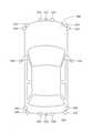
図1は、本実施形態に係る駐車支援システム10のシステム構成を示すブロック図である。図2は、本実施形態に係る駐車支援システム10を搭載した車両200の上面図である。図3は、本実施形態に係る車両200のダッシュボード290の構成を示す図である。図1~図3を参照して駐車支援システム10の構成を説明する。<< Configuration of parking support system >>
FIG. 1 is a block diagram showing a system configuration of the
図1に示すように、駐車支援システム10は、自動駐車制御ユニット100、カメラ群210、ソナー群220、慣性センサ241、車輪速センサ242、入力機器群250、出力機器群260、ブレーキシステム270、駆動システム275、トランスミッションシステム280、およびEPSシステム285を含んで構成される。カメラ群210、ソナー群220、慣性センサ241、車輪速センサ242、入力機器群250、出力機器群260、ブレーキシステム270、駆動システム275、トランスミッションシステム280、およびEPSシステム285は、直接に自動駐車制御ユニット100に結線されていてもよいし、CAN(Controller Area Network)を介して接続されていてもよい。 As shown in FIG. 1, the
≪駐車支援システムの構成:センサ類≫
カメラ群210は、図2に示す車両200に搭載された複数台のカメラ211~214である。詳しくは、車両200は、車両200の前方に設けられ、車両200の前方を撮像するカメラ211を備える。また、車両200は、車両200の後方に設けられ、車両200の後方を撮像するカメラ213を備える。<< Configuration of parking support system: Sensors >>
The
本実施形態では、車両200は、車両200の右ドアミラーの先端に設けられ車両200の右側を撮像するカメラ212、および、車両200の左ドアミラーの先端に設けられ車両200の左側を撮像するカメラ214を備える。カメラ212,214は、ドアミラーの先端以外の箇所に設けられてもよいが、ドアミラーが撮像画像に大きく写り込むことがない箇所に設けられることが望ましい。
カメラ211~214が撮像した車両200の周辺の画像は、自動駐車制御ユニット100に出力される。画像には、路面や他車両、歩行者が含まれる(写っている)。In the present embodiment, the
The images around the
ソナー群220は、図2に示す車両200に搭載された複数台のソナー221~232である。詳しくは、本実施形態での車両200は、車両200の前方にほぼ等間隔で並ぶ4台のソナー221~224を備える。4台のソナー221~224は、車両200の前方の障害物を検知する。また、車両200は、車両200の後方にほぼ等間隔で並ぶ4台のソナー227~230を備える。4台のソナー227~230は、車両200の後方の障害物を検知する。 The sonar group 220 is a plurality of
さらに、本実施形態での車両200は、車両200の右前方部側方にソナー225を備える。ソナー225は、車両200の右前方から右側の障害物を検知する。また、車両200は、車両200の右後方部側方にソナー226を備える。ソナー226は、車両200の右後方から右側の障害物を検知する。
車両200は、車両200の左前方部側方にソナー232を備える。ソナー232は、車両200の左前方から左側の障害物を検知する。また、車両200は、車両200の左後方部側方にソナー231を備える。ソナー231は、車両200の左後方から左側の障害物を検知する。
側面にあるソナー225,226,231,232は、近距離にあり、車両200が巻き込む可能性のある障害物を検知する。ソナー221~232が検知した障害物の情報は、自動駐車制御ユニット100に出力される。Further, the
The
上記したカメラやソナーの台数や設置位置は上記の内容に限定されるものではなく、台数を増減したり、設置位置を変更したりしてもよい。但し、カメラ、ソナーとも、極力、車両200の全周の状況を検知できるように台数や設置位置を選択することが望ましい。
また、車両200は、レーダやLIDAR(Light Detection and Ranging)を備えてもよい。レーダは、車両や歩行者を含む物標にレーダ波を照射する一方、物標で反射されたレーダ波を受信することにより、物標までの距離や物標の方位を含む物標の分布情報を取得する。LIDARは、例えば、照射光に対する散乱光の検出に要する時間を計測することにより、物標の有無、および物標までの距離を検出する。駐車支援システム10は、レーダとLIDARの双方を用いて、物標を検知するようにしてもよい。
慣性センサ241は、車両200の加速度を検出するセンサである。車輪速センサ242は、車両200の各車輪の車輪速を検出するセンサである。The number and installation position of the above-mentioned cameras and sonars are not limited to the above contents, and the number of cameras and sonars may be increased or decreased or the installation position may be changed. However, it is desirable to select the number and installation position of both the camera and sonar so that the situation around the entire circumference of the
Further, the
The inertia sensor 241 is a sensor that detects the acceleration of the
≪自動駐車システムの構成:入出力装置≫
出力機器群260(図1参照)は、ダッシュボード290(図3参照)に備えられ、車室内の乗員に各種情報を提示する。表示装置263は、運転席に正対する位置に設けられるメータパネルであって、例えば、スピードメータ、タコメータ、オドメータ、シフト位置情報、灯火類の点灯状況情報などが表示される。
ダッシュボード290右側の表示装置264には、カメラ212(図2参照)が撮像した車両200の右側における後方および下方の画像が表示される。ダッシュボード280左側の表示装置261には、カメラ214が撮像した車両200の左側における後方および下方の画像が表示される。≪Automatic parking system configuration: Input / output device≫
The output device group 260 (see FIG. 1) is provided on the dashboard 290 (see FIG. 3) and presents various information to the occupants in the vehicle interior. The
The
車幅方向に横長の表示装置262は、マルチインフォメーションパネルであって、例えば、車両200周辺の地図情報、地図上における車両200の現在位置情報、現在の走行路・予定経路に関する交通情報(信号情報を含む)などが表示される。また、表示装置262には、斜上面視画像および直上面視画像が表示される(後記する図5~図11参照)。
出力機器群260には、画像を出力する表示装置261~264の他に、音声を出力するスピーカが含まれる。The
The output device group 260 includes speakers that output audio in addition to the
入力機器群250は、ダッシュボード290やステアリングホイール291(図3参照)に備えられるスイッチである。表示装置262は、タッチパネルディスプレイであって、入力機器群250の1つである。自動駐車スイッチ251は、ステアリングホイール291に備わる入力機器である。運転手が、自動駐車スイッチ251を押すことで、自動駐車制御ユニット100が、自動駐車処理(後記する図4参照)を開始する。 The
≪自動駐車システムの構成:動力系≫
図1に戻って、ブレーキシステム270は、車両200の制動を行うシステムである。ブレーキシステム270は、車両200の制動を行うブレーキ装置やブレーキ装置を制御するブレーキコントロールユニットを備える。≪Automatic parking system configuration: Power system≫
Returning to FIG. 1, the
駆動システム275は、車両200を走行させるシステムである。例えば、車両200がハイブリッド車ならば、駆動システム275は、駆動源としてエンジンおよびモータ・ジェネレータの他に、ハイブリッドコントロールユニットを備える。車両200がガソリン車ならば、エンジンのみを駆動源とする。車両200が燃料電池車を含む電気自動車ならば、モータのみを駆動源とする。 The
トランスミッションシステム280は、車両200の変速を行うシステムである。トランスミッションシステム280は、車両200の変速を行うトランスミッションと、トランスミッションを制御するトランスミッションコントロールユニットと、トランスミッションと接続されたシフトレバーとを備える。 The
EPSシステム285は、運転者の操舵をアシストする電動パワーステアリングシステムである。EPSシステム285は、ステアリングホイール291が設けられた操舵軸と、操舵軸を回転駆動する駆動モータと、駆動モータを制御するEPSコントロールユニットとを備える。EPSシステム285は、駆動モータを駆動源として操舵軸を回転させ、運転者がステアリングホイール291を回転させて操舵する操作をアシストする。 The
≪駐車支援システムの構成:自動駐車制御ユニット≫
自動駐車制御ユニット100(駐車支援装置)は、ECU(Electronic Control Unit)から構成され、制御プログラムに基づいて実行する処理によって、認識部110、挙動制御部120、自動駐車制御部130、および表示制御部140の機能を実現する。なお、制御プログラム(単にプログラムとも記す)は、自動駐車制御ユニット100に記憶される。<< Configuration of parking support system: Automatic parking control unit >>
The automatic parking control unit 100 (parking support device) is composed of an ECU (Electronic Control Unit), and a recognition unit 110, a
認識部110は、カメラ群210が撮像した画像、およびソナー群220が検知した障害物の情報から車両周辺(外界)を認識する。例えば、認識部110は、カメラ群210が撮像した画像から、駐車枠331(後記する図5参照)を認識(検出)する。認識部110は、車両200が駐車可能な駐車スペース(後記する図6記載の駐車スペース枠332に囲われた領域)を認識(検出)する。 The recognition unit 110 recognizes the periphery of the vehicle (outside world) from the image captured by the
挙動制御部120は、ブレーキシステム270、駆動システム275、トランスミッションシステム280、およびEPSシステム285に指示して、車両200の操舵、加減速を行う。挙動制御部120は、自動駐車制御部130が出力した目標移動経路を車両200が走行するように、ブレーキシステム270、駆動システム275、トランスミッションシステム280、およびEPSシステム285を制御する。 The
自動駐車制御部130は、自動駐車処理(後記する図4参照)を実行し、駐車支援システム10全体を制御する。詳しくは、自動駐車スイッチ251が押されたことを検知すると、自動駐車制御部130は、表示制御部140に自動駐車機能画面300~306(後記する図5~図11参照)を表示するように指示する。次に、自動駐車制御部130は、認識部110に駐車スペース枠332(後記する図6参照)の位置を表示制御部140に出力するように指示する。表示制御部140は、認識部110が出力した駐車スペース枠332を表示する。 The automatic
ブレーキペダルが操作されて(踏まれて)車両200が停止し、運転手により駐車スペースが選択されると、自動駐車制御部130は、現在の停止位置から選択された駐車スペース(目標駐車位置)までの障害物を回避する目標移動経路を算出する。障害物の情報は、ソナー群220から得られる。自動駐車制御部130は、目標移動経路を挙動制御部120に出力する。挙動制御部120の制御下で車両200は、駐車スペースに移動し停止する。続いて、自動駐車制御部130は、表示制御部140に、自動駐車機能画面の表示を終了するように指示する。 When the brake pedal is operated (stepped on) to stop the
表示制御部140は、カメラ群210が撮像した画像を合成して、斜上面視画像を生成し、表示装置262に出力する。斜上面視画像には、車両200の後方から前方を向いた視点から見える斜上面視画像(後記する図5の前方斜上面視画像311参照)と、車両200の前方から後方を向いた視点から見える斜上面視画像(後記する図9記載の後方斜上面視画像312参照)とがある。表示制御部140は、カメラ群210が撮像した画像を合成して、車両200を直上方から見下ろす視点から見える直上面視画像313(後記する図5~図11参照)を生成し、表示装置262に出力する。表示装置262には、斜上面視画像と直上面視画像とが並んで表示される。 The
表示制御部140は、車両が前進しているときには車両の後方から前方を向いた視点から見える前方斜上面視画像を生成して表示装置262に出力する。このとき、表示制御部140は、車両200のフロント領域を半透明にし、運転手の死角となっている車両の前側が見えるように前方斜上面視画像を生成する(後記する図8参照)。 The
表示制御部140は、車両が後進しているときには車両の前方から後方を向いた視点から見える後方斜上面視画像を生成して表示装置262に出力する。このとき、表示制御部140は、車両200のバック領域を半透明にし、運転手の死角となっている車両の後側が見えるように後方斜上面視画像を生成する(後記する図9参照)。
なお、表示制御部140が、車両200のフロント領域やバック領域を常に半透明にするとは限らない。表示制御部140が、車両200のフロント領域やバック領域を半透明にするタイミングについては後記する。The
The
≪自動駐車処理≫
駐車支援システム10の動作を説明する前に、駐車支援システム10の操作方法を説明する。運転手が、自動駐車スイッチ251(図3参照)をオンにすると、駐車支援システム10が起動し、自動駐車機能画面300(後記する図5参照)が表示装置262に表示される。駐車支援システム10は、駐車枠を認識し、車両200が駐車可能な駐車スペースを探し出して、自動駐車機能画面301(後記する図6参照)を表示する。≪Automatic parking process≫
Before explaining the operation of the
運転手は、駐車する駐車スペースの近くで車両200を止める。続いて運転手は、表示装置262(タッチパネルディスプレイ)に表示された駐車する駐車スペースをタッチして、駐車する駐車スペースを選択する。すると、駐車支援システム10は、スピーカから「自動駐車運転を始めます。ハンドルから手を離し、ブレーキペダルから足を離して下さい。」という音声メッセージを出力する。
音声メッセージを聞いた運転手が、ブレーキペダルの操作を止める(ブレーキペダルから足を離す)。駐車支援システム10は、車両200を走行させて、選択された駐車スペースに停止し、自動駐車機能画面の表示を終了する。The driver stops the
The driver who hears the voice message stops operating the brake pedal (takes his foot off the brake pedal). The
図4は、本実施形態に係る自動駐車処理のフローチャートである。以下、運転手が、車両200を前進走行させながら、並列駐車の駐車場内で駐車スペースを探しているところから説明を始める。
ステップS11において自動駐車制御部130は、自動駐車スイッチ251(図4では「自動駐車SW」と記載)が押されたならば(ステップS11→YES)ステップS12に進み、自動駐車スイッチ251が押されていないならば(ステップS11→NO)ステップS11に戻る。FIG. 4 is a flowchart of the automatic parking process according to the present embodiment. Hereinafter, the explanation starts from the place where the driver is searching for a parking space in the parking lot of parallel parking while moving the
In step S11, the automatic
ステップS12において自動駐車制御部130は、表示制御部140に自動駐車機能画面の表示を指示する。表示制御部140は、カメラ群210が撮像した画像から前方斜上面視画像および直上面視画像を生成して表示装置262に表示する。
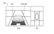
図5は、本実施形態に係る自動駐車機能画面300を説明するための図である。自動駐車機能画面300として、前方斜上面視画像311と、直上面視画像313とが表示されている。車両200は、前進しているので前方斜上面視画像311が表示されている。後進している場合には、後方斜上面視画像312(後記する図9参照)が表示される。In step S12, the automatic
FIG. 5 is a diagram for explaining the automatic
前方斜上面視画像311、および直上面視画像313には、カメラ群210が撮像した駐車枠331を含めた車両200の周辺が表示されている。また、自車両321である車両200も重ねて表示されている。自車両321は、透けて表示される。透けた自車両321については、後記する図8、図9を参照して説明する。 The front oblique
図4に戻って、ステップS13において自動駐車制御部130は、認識部110に駐車スペース枠を表示するように指示する。認識部110は、カメラ群210が撮像した画像から駐車枠331を認識し、さらに車両が駐車可能な駐車スペースを探索して検出する。認識部110は、検出した駐車スペースの位置を表示制御部140に出力する。表示制御部140は、前方斜上面視画像311および直上面視画像313に駐車スペースを表示する。 Returning to FIG. 4, in step S13, the automatic
図6は、本実施形態に係る駐車スペースを表示した自動駐車機能画面301を説明するための図である。表示制御部140は、駐車スペースの枠を点線の駐車スペース枠332として重ねて前方斜上面視画像311および直上面視画像313を生成して、表示装置262に出力する。 FIG. 6 is a diagram for explaining an automatic
図4に戻って、ステップS14において自動駐車制御部130は、ブレーキが操作された(ブレーキペダルが踏まれた)ならば(ステップS14→YES)ステップS15に進み、ブレーキが操作されていないならば(ステップS14→NO)ステップS13に戻る。ステップS15に進んだ時点で、車両200は停止している。自動駐車制御部130は、ブレーキ操作の状態をブレーキシステム270から取得する。 Returning to FIG. 4, in step S14, the automatic
ステップS15において自動駐車制御部130は、駐車位置(駐車スペース)が選択されたならば(ステップS15→YES)ステップS16に進み、駐車位置が選択されていないならば(ステップS15→NO)ステップS13に戻る。運転手は、タッチパネルディスプレイである表示装置262に表示された駐車スペースのなかで、駐車を希望する駐車スペースにタッチすることで駐車位置を選択する。
駐車位置が選択されると、自動駐車制御部130は、選択された駐車スペースを強調して表示するように表示制御部140に指示する。指示を受けると、表示制御部140は、選択された駐車スペースを強調して表示する。In step S15, the automatic
When the parking position is selected, the automatic
図7は、本実施形態に係る選択された駐車スペース333が強調表示された自動駐車機能画面302を説明するための図である。表示制御部140は、選択された駐車スペース333を強調された領域(図7では格子模様でハッチング)として前方斜上面視画像311および直上面視画像313を生成して、表示装置262に出力する。 FIG. 7 is a diagram for explaining an automatic
図4に戻って、ステップS16において自動駐車制御部130は、自動駐車の開始メッセージを出力する。例えば、「自動駐車運転を始めます。ハンドルから手を離し、ブレーキペダルから足を離して下さい。」という音声をスピーカから出力する。自動駐車制御部130は、同じ趣旨のテキストメッセージを表示装置262に表示するように表示制御部140に指示してもよい。 Returning to FIG. 4, in step S16, the automatic
ステップS17において自動駐車制御部130は、ブレーキが操作されている(ブレーキペダルが踏まれたまま)ならば(ステップS17→YES)ステップS17に戻り、ブレーキが操作されていない(ブレーキペダルが踏まれていない)ならば(ステップS17→NO)ステップS18に進む。運転手が、ブレーキペダルから足を離すと、ステップS18に進む。 In step S17, the automatic
ステップS18において自動駐車制御部130は、現在停止している位置から選択された駐車スペース333(図7参照)までの障害物を回避する目標移動経路を算出する。障害物の情報は、ソナー群220から得られる。自動駐車制御部130は、目標移動経路を挙動制御部120に出力する。目標移動経路を受け付けると挙動制御部120は、車両200が目標移動経路を走行するように、ブレーキシステム270、駆動システム275、トランスミッションシステム280、およびEPSシステム285を制御する。 In step S18, the automatic
以下では、ステップS18で算出された目標移動経路は、最初に車両200が前進して、ステアリングホイール291を右に切って切り返し位置で一旦停止し、次に切り返して後進して選択された駐車スペース333(図7参照)に入庫する経路であるとして説明する。
図8は、本実施形態に係る車両200が前進中の自動駐車機能画面303を説明するための図である。自動駐車中で車両200が前進しているときには、表示制御部140は、前方斜上面視画像311を生成して、表示装置262に出力する。駐車スペースは選択済みであるため、前方斜上面視画像311および直上面視画像313は、駐車スペース枠332(図6参照)を含まない。直上面視画像313には選択された駐車スペース333が強調して表示されている。しかし、選択された駐車スペース333は車両200の後方にあるため、前方斜上面視画像311には含まれない。In the following, in the target movement route calculated in step S18, the
FIG. 8 is a diagram for explaining the automatic
前方斜上面視画像311において、自車両321である車両200と駐車枠331が一部重なっているが、車両200の前方部分(フロント領域とも記す)は透けており、駐車枠331が見えている(図8では駐車枠331を点線で記載)。なお、自車両321が透ける度合いは、前方斜上面視画像311で上側(前側)が高く(より透ける)、下側(後側)が低く(より不透明)、車両200の後側より前側の方がより見えるようになっている(図8では、前側より後側を濃くハッチング)。 In the front oblique
図9は、本実施形態に係る車両200が後進中の自動駐車機能画面304を説明するための図である。自動駐車中で車両200が後進しているときには、表示制御部140は、後方斜上面視画像312を生成して、表示装置262に出力する。駐車スペースは選択済みであるため、後方斜上面視画像312および直上面視画像313は、駐車スペース枠332(図6参照)を含まない。後方斜上面視画像312、および直上面視画像313には選択された駐車スペース333が表示されている。 FIG. 9 is a diagram for explaining the automatic
後方斜上面視画像312において、自車両321である車両200と駐車枠331が一部重なっているが、車両200の後方部分(バック領域とも記す)は透けており、駐車枠331と選択された駐車スペース333とが見えている(図9では駐車枠331を点線で記載)。なお、自車両321が透ける度合いは、後方斜上面視画像312で上側(後側)が高く(より透ける)、下側(前側)が低く(より不透明)、車両200の前側より後側の方がより見えるようになっている(図9では、後側より前側を濃くハッチング)。 In the rear oblique
図10は、本実施形態に係る選択された駐車スペース333に停止した直後の自動駐車機能画面305を説明するための図である。後進して停止したため、表示制御部140は、後方斜上面視画像312を生成して表示装置262に出力し続けている。選択された駐車スペース333への駐車は完了しており、選択された駐車スペース333は表示されていない。後方斜上面視画像312において、自車両321である車両200と駐車枠331が一部重なっているが、車両200の後方部分は透けており、駐車枠331が見えている(図10では駐車枠331を点線で記載)。 FIG. 10 is a diagram for explaining the automatic
図4に戻って、ステップS19において自動駐車制御部130は、表示制御部140に、自車両321の半透明表示の終了を指示する。指示を受けて表示制御部140は、自車両321である車両200の半透明表示を終了する。
図11は、本実施形態に係る自車両321の半透明表示が終了した自動駐車機能画面306を説明するための図である。後方斜上面視画像312において、自車両321は半透明ではなく、自車両321である車両200と重なっている駐車枠331は見えない。
図4に戻って、ステップS20において自動駐車制御部130は、ステップS19における半透明表示の終了し、所定の時間が経過したら、自動駐車機能画面306の表示を終了する。Returning to FIG. 4, in step S19, the automatic
FIG. 11 is a diagram for explaining the automatic
Returning to FIG. 4, in step S20, the automatic
≪駐車支援システムの特徴≫
駐車支援システム10は、車両200が前進しているときには、カメラ群210が撮像した画像から前方斜上面視画像311を合成して表示装置262に表示する。また、駐車支援システム10は、車両200が後進しているときには、カメラ群210が撮像した画像から後方斜上面視画像312を合成して表示装置262に表示する。≪Characteristics of parking support system≫
When the
前方斜上面視画像311には、前方(フロント領域)が半透明になった自車両321が含まれる(図8参照)。また、後方斜上面視画像312には、後方(バック領域)が半透明になった自車両321が含まれる(図9参照)。進行方向に応じて自車両321の一部を半透明にしたことで、駐車支援システム10は、進行方向で運転手の死角となっている車両周辺の状況を表示することができる。これにより、運転手に安心感を与えることができる。 The front oblique
≪変形例≫
本発明は、上記した実施形態の記載だけに限定されない。上記した実施形態において自動駐車制御ユニット100は、1つのECUで構成されるとしたが複数であってもよい。
上記した実施形態において、自動駐車中に斜上面視画像(3次元ビュー画像)の自車両が半透明で表示されている。自動駐車中に限らず、MVC(Multi View Camera)の起動など、車両周辺画像の表示指示があった場合に、半透明表示の自車両を含む斜上面視画像を表示するようにしてもよい。≪Variation example≫
The present invention is not limited to the description of the above-described embodiment. In the above-described embodiment, the automatic
In the above-described embodiment, the own vehicle in the oblique top view image (three-dimensional view image) is displayed semi-transparently during automatic parking. Not limited to automatic parking, when there is an instruction to display a vehicle peripheral image such as activation of an MVC (Multi View Camera), an oblique top view image including the own vehicle in a semi-transparent display may be displayed.
上記した実施形態では、自動駐車完了後に、自車両の半透明表示を終了しているが(図4のステップS19参照)、自車両の半透明表示を継続してもよい。
また、上記した実施形態では、自動駐車スイッチ251が押されて自動駐車機能画面300が表示された時点で自車両が半透明表示なっている(図4記載のステップS11~S12、図5、図6参照)。これに対して、駐車位置が選択されるまで(図5~図6に対応)は不透明表示であり、ステップS15で駐車位置が選択されから半透明表示するようにしてもよい(図7~図10に対応)。
上記した実施形態における自動駐車の開始手順は、自動駐車スイッチのオン(ステップS11参照)、ブレーキ操作(ステップS14参照)、駐車位置選択(ステップS15参照)、ブレーキ操作の停止(ステップS17参照)であったが、他の手順であってもよい。In the above-described embodiment, the semi-transparent display of the own vehicle is finished after the automatic parking is completed (see step S19 in FIG. 4), but the semi-transparent display of the own vehicle may be continued.
Further, in the above-described embodiment, the own vehicle is displayed semi-transparently when the
The procedure for starting automatic parking in the above-described embodiment is as follows: on (see step S11), brake operation (see step S14), parking position selection (see step S15), and stop of brake operation (see step S17). There was, but other procedures may be used.
上記した実施形態では、前方斜上面視画像311における自車両321(フロント領域)の半透明表示と、後方斜上面視画像312における自車両321(バック領域)の半透明表示とは、自車両321の画像中で下側から上側に透ける度合いが同様に段階的に高くなっている(図5~図10ではハッチングについて濃さの変化の度合い(グラデーション)が同様)。これに対して、前方斜上面視画像311と後方斜上面視画像312とで、自車両321の半透明表示を異なるようにしてもよい。運転手の死角領域は後側が広いので、後方斜上面視画像312における自車両321(バック領域)について、透ける度合いが高い領域を広くするようにしてもよい。 In the above-described embodiment, the semi-transparent display of the own vehicle 321 (front area) in the front oblique
図12は、本実施形態の変形例に係る自車両321Aの画像において透ける度合いが高い領域が広い後方斜上面視画像312Aを説明するための図である。図10記載の後方斜上面視画像312の自車両321と比較すると透ける度合いが高い領域が広くなっている。このため、運転手の死角領域がより鮮明に表示され、運転手は車両200の後方の状況をより把握しやすくなっている。 FIG. 12 is a diagram for explaining a rear oblique
上記した実施形態および変形例では、自車両321,321Aは、下側から上側に半透明の度合いが段階的に高くなっている。半透明と不透明の2段階にしてもよい。また、前方斜上面視画像における自車両(フロント領域)の半透明領域と、後方斜上面視画像における自車両(バック領域)の半透明領域の範囲が異なるようにしてもよい。 In the above-described embodiment and modification, the degree of translucency of the
10 駐車支援システム
100 自動駐車制御ユニット(駐車支援装置)
110 認識部
120 挙動制御部
130 自動駐車制御部
140 表示制御部
200 車両
210 カメラ群
211~214 カメラ(撮像装置)
220 ソナー群
221~232 ソナー
250 入力機器群
251 自動駐車スイッチ
260 出力機器群
261~264 表示装置
270 ブレーキシステム
275 駆動システム
280 トランスミッションシステム
285 EPSシステム
300~306 自動駐車機能画面
311 前方斜上面視画像(斜上面視画像、車両周辺状況の画像、3次元ビュー画像)
312 後方斜上面視画像(斜上面視画像、車両周辺状況の画像、3次元ビュー画像)
313 直上面視画像(俯瞰画像)
321,321A 自車両(車体画像)
331 駐車枠
332 駐車スペース枠
333 選択された駐車スペース(目標駐車位置)10
110
220
312 Rear oblique top view image (oblique top view image, image of vehicle surroundings, 3D view image)
313 Direct top view image (overhead image)
3211,321A own vehicle (body image)
331
Claims (9)
Translated fromJapanese前記車両の挙動制御を行う挙動制御部と、
所定の手段で決定した目標駐車位置への前記車両の駐車動作を行う自動駐車制御部と、
前記車両が備える撮像装置が撮像した画像から車両周辺状況の画像を生成して、前記車両に備わる表示装置に表示する表示制御部とを備え、
前記表示制御部は、前記車両の車体画像と前記車両周辺状況の画像とを重ねて表示を行うと共に、前記車体画像のドライバーの死角となる部分領域を半透明にし、前記車両の進行方向に応じて、半透明になる前記車体画像の部分領域を切り換えること
を特徴とする駐車支援装置。A recognition unit that recognizes the outside world of the vehicle,
The behavior control unit that controls the behavior of the vehicle and
An automatic parking control unit that performs a parking operation of the vehicle to a target parking position determined by a predetermined means,
It is provided with a display control unit that generates an image of a vehicle peripheral situation from an image captured by the image pickup device provided in the vehicle and displays it on a display device provided in the vehicle.
The display control unitsuperimposes and displays an image of the vehicle body of the vehicle and an image of the situation around the vehicle, and makes apartial region of the vehicle body image, which is a blind spot of the driver, semi-transparent, according to the traveling direction of the vehicle. A parking support device characterized by switching apartial area of the vehicle body image that becomes translucent.
前記車両が前進しているときは、前記車体画像のフロント領域を半透明にし、
前記車両が後進しているときは、前記車体画像のバック領域を半透明にする
ことを特徴とする請求項1に記載の駐車支援装置。The display control unit
When the vehicle is moving forward, the front area of the vehicle body image is made translucent.
The parking support device according to claim 1, wherein when the vehicle is moving backward, the back area of the vehicle body image is made translucent.
前記車両の半透明にした領域に、実際の路面の画像を重ね合わせる
ことを特徴とする請求項1に記載の駐車支援装置。The display control unit
The parking support device according to claim 1, wherein an image of an actual road surface is superimposed on the translucent area of the vehicle.
前記車両の3次元ビュー画像、および自車両の全周に亘る画像を生成する
ことを特徴とする請求項1に記載の駐車支援装置。The display control unit
The parking support device according to claim 1, wherein a three-dimensional view image of the vehicle and an image over the entire circumference of the own vehicle are generated.
前記自車両の全周に亘る画像に含まれる前記車体画像は不透明である
ことを特徴とする請求項4に記載の駐車支援装置。The vehicle body image included in the three-dimensional view image is translucent.
The parking support device according to claim 4, wherein the vehicle body image included in the image over the entire circumference of the own vehicle is opaque.
ことを特徴とする請求項1に記載の駐車支援装置。The parking support device according to claim 1, wherein the translucent area of the vehicle is made opaque when the parking operation of the vehicle is completed.
ことを特徴とする請求項2に記載の駐車支援装置。The parking support device according to claim 2, wherein the translucent range differs between the front area and the back area.
前記駐車支援装置は、
車両の外界を認識するステップと、
前記車両の挙動制御を行うステップと、
所定の手段で決定した目標駐車位置への前記車両の駐車動作を行うステップと、
前記車両が備える撮像装置が撮像した画像から車両周辺状況の画像を生成して、前記車両に備わる表示装置に表示するステップと、
前記車両の車体画像と前記車両周辺状況の画像とを重ねて表示を行うと共に、前記車体画像のドライバーの死角となる部分領域を半透明にし、前記車両の進行方向に応じて、半透明になる前記車体画像の部分領域を切り換えるステップと
を実行とすることを特徴とする駐車支援方法。It is a parking support method for parking support devices.
The parking support device is
Steps to recognize the outside world of the vehicle and
The step of controlling the behavior of the vehicle and
A step of parking the vehicle to a target parking position determined by a predetermined means, and
A step of generating an image of a vehicle peripheral situation from an image captured by an image pickup device provided in the vehicle and displaying it on a display device provided in the vehicle.
The vehicle body image of the vehicle and the image of the vehicle surroundingsare superimposed and displayed, and thepartial area of the vehicle body image that becomes the driver's blind spot is made translucent, and becomes translucent according to the traveling direction of the vehicle. A parking support method characterized in that a step of switching apartial area of a vehicle body image is executed.
Priority Applications (3)
| Application Number | Priority Date | Filing Date | Title |
|---|---|---|---|
| JP2019225906AJP7018923B2 (en) | 2019-12-13 | 2019-12-13 | Parking Assistance Equipment, Parking Assistance Methods and Programs |
| CN202011446635.6ACN113060127B (en) | 2019-12-13 | 2020-12-08 | Parking assist device, parking assist method, and program |
| US17/118,710US11697408B2 (en) | 2019-12-13 | 2020-12-11 | Parking assisting device, parking assisting method and storage medium storing program for the parking assisting device |
Applications Claiming Priority (1)
| Application Number | Priority Date | Filing Date | Title |
|---|---|---|---|
| JP2019225906AJP7018923B2 (en) | 2019-12-13 | 2019-12-13 | Parking Assistance Equipment, Parking Assistance Methods and Programs |
Publications (2)
| Publication Number | Publication Date |
|---|---|
| JP2021097281A JP2021097281A (en) | 2021-06-24 |
| JP7018923B2true JP7018923B2 (en) | 2022-02-14 |
Family
ID=76316565
Family Applications (1)
| Application Number | Title | Priority Date | Filing Date |
|---|---|---|---|
| JP2019225906AActiveJP7018923B2 (en) | 2019-12-13 | 2019-12-13 | Parking Assistance Equipment, Parking Assistance Methods and Programs |
Country Status (3)
| Country | Link |
|---|---|
| US (1) | US11697408B2 (en) |
| JP (1) | JP7018923B2 (en) |
| CN (1) | CN113060127B (en) |
Cited By (1)
| Publication number | Priority date | Publication date | Assignee | Title |
|---|---|---|---|---|
| US20210179086A1 (en)* | 2019-12-13 | 2021-06-17 | Honda Motor Co., Ltd. | Parking assisting device, parking assisting method and storage medium storing program for the parking assisting device |
Families Citing this family (2)
| Publication number | Priority date | Publication date | Assignee | Title |
|---|---|---|---|---|
| US12054097B2 (en)* | 2020-12-15 | 2024-08-06 | Panasonic Automotive Systems Company Of America, Division Of Panasonic Corporation Of North America | Target identification for vehicle see-through applications |
| JP7632338B2 (en)* | 2022-02-16 | 2025-02-19 | トヨタ自動車株式会社 | Remote image display method and remote image display system |
Citations (5)
| Publication number | Priority date | Publication date | Assignee | Title |
|---|---|---|---|---|
| JP2014036326A (en) | 2012-08-08 | 2014-02-24 | Honda Motor Co Ltd | Bird's eye image display device |
| JP2014072604A (en) | 2012-09-28 | 2014-04-21 | Fujitsu Ten Ltd | Image processing system, image processing device, image processing method and program |
| JP2014198531A (en) | 2013-03-29 | 2014-10-23 | アイシン精機株式会社 | Image display controller, image display system, and display unit |
| JP2017126834A (en) | 2016-01-12 | 2017-07-20 | 株式会社デンソー | Driving support device and driving support method |
| JP2019103044A (en) | 2017-12-06 | 2019-06-24 | クラリオン株式会社 | Image display device and parking support system |
Family Cites Families (49)
| Publication number | Priority date | Publication date | Assignee | Title |
|---|---|---|---|---|
| JP3149870B2 (en)* | 1999-05-11 | 2001-03-26 | 株式会社豊田自動織機製作所 | Vehicle reverse support device |
| US7212653B2 (en)* | 2001-12-12 | 2007-05-01 | Kabushikikaisha Equos Research | Image processing system for vehicle |
| JP4593070B2 (en)* | 2001-12-12 | 2010-12-08 | 株式会社エクォス・リサーチ | Image processing apparatus for vehicle |
| JP3968271B2 (en)* | 2002-06-25 | 2007-08-29 | 株式会社オートネットワーク技術研究所 | Vehicle periphery visual recognition device |
| JP3979330B2 (en)* | 2003-04-02 | 2007-09-19 | トヨタ自動車株式会社 | Image display device for vehicle |
| JP3797343B2 (en)* | 2003-05-12 | 2006-07-19 | 株式会社デンソー | Vehicle periphery display device |
| JP2005001570A (en)* | 2003-06-12 | 2005-01-06 | Equos Research Co Ltd | Parking assistance device |
| JP5380941B2 (en)* | 2007-10-01 | 2014-01-08 | 日産自動車株式会社 | Parking support apparatus and method |
| JP5421788B2 (en)* | 2008-02-20 | 2014-02-19 | クラリオン株式会社 | Vehicle periphery image display system |
| JP5118605B2 (en)* | 2008-10-30 | 2013-01-16 | クラリオン株式会社 | Vehicle periphery image display system |
| JP5134504B2 (en) | 2008-11-06 | 2013-01-30 | クラリオン株式会社 | Vehicle perimeter monitoring system |
| DE102009020328A1 (en)* | 2009-05-07 | 2010-11-11 | Bayerische Motoren Werke Aktiengesellschaft | A method for displaying differently well visible objects from the environment of a vehicle on the display of a display device |
| JP5108837B2 (en)* | 2009-07-13 | 2012-12-26 | クラリオン株式会社 | Vehicle blind spot image display system and vehicle blind spot image display method |
| EP2512134B1 (en)* | 2009-12-07 | 2020-02-05 | Clarion Co., Ltd. | Vehicle periphery monitoring system |
| US20120249789A1 (en)* | 2009-12-07 | 2012-10-04 | Clarion Co., Ltd. | Vehicle peripheral image display system |
| JP5187369B2 (en)* | 2010-09-24 | 2013-04-24 | 株式会社デンソー | Reverse parking assist device for vehicle and program for reverse parking assist device |
| JP5516992B2 (en)* | 2010-11-30 | 2014-06-11 | アイシン精機株式会社 | Parking position adjustment device |
| JP6056612B2 (en)* | 2013-03-29 | 2017-01-11 | アイシン精機株式会社 | Image display control device and image display system |
| JP6148887B2 (en)* | 2013-03-29 | 2017-06-14 | 富士通テン株式会社 | Image processing apparatus, image processing method, and image processing system |
| US9280202B2 (en)* | 2013-05-10 | 2016-03-08 | Magna Electronics Inc. | Vehicle vision system |
| JP6380410B2 (en)* | 2014-01-10 | 2018-08-29 | アイシン精機株式会社 | Image display control device and image display system |
| JP6565148B2 (en)* | 2014-09-05 | 2019-08-28 | アイシン精機株式会社 | Image display control device and image display system |
| US20180134217A1 (en)* | 2015-05-06 | 2018-05-17 | Magna Mirrors Of America, Inc. | Vehicle vision system with blind zone display and alert system |
| US20170061689A1 (en)* | 2015-08-24 | 2017-03-02 | Caterpillar Inc. | System for improving operator visibility of machine surroundings |
| JP7010221B2 (en)* | 2016-07-13 | 2022-01-26 | ソニーグループ株式会社 | Image generator, image generation method, and program |
| JP6877115B2 (en)* | 2016-09-27 | 2021-05-26 | 株式会社東海理化電機製作所 | Vehicle visibility device |
| JP6876236B2 (en)* | 2016-09-30 | 2021-05-26 | 株式会社アイシン | Display control device |
| DE102016223391A1 (en)* | 2016-11-25 | 2018-05-30 | Conti Temic Microelectronic Gmbh | METHOD AND DEVICE FOR PRODUCING A VEHICLE ENVIRONMENT VIEW ON A VEHICLE |
| JP6839044B2 (en)* | 2017-07-24 | 2021-03-03 | 本田技研工業株式会社 | Driving support device and driving support method |
| CN110945866B (en)* | 2017-08-03 | 2021-07-27 | 三菱电机株式会社 | Vehicle surrounding image display device and vehicle surrounding image display method |
| JP7056034B2 (en)* | 2017-08-14 | 2022-04-19 | 株式会社アイシン | Peripheral monitoring device |
| JP6504529B1 (en)* | 2017-10-10 | 2019-04-24 | マツダ株式会社 | Vehicle display device |
| JP6740991B2 (en)* | 2017-11-10 | 2020-08-19 | 株式会社デンソー | Display processor |
| JP7426174B2 (en)* | 2018-10-26 | 2024-02-01 | 現代自動車株式会社 | Vehicle surrounding image display system and vehicle surrounding image display method |
| JP7283059B2 (en)* | 2018-11-28 | 2023-05-30 | 株式会社アイシン | Perimeter monitoring device |
| EP3663941B1 (en)* | 2018-12-07 | 2022-07-13 | Volvo Car Corporation | Evaluation of a simulated vehicle-related feature |
| KR20210100611A (en)* | 2018-12-11 | 2021-08-17 | 소니그룹주식회사 | Image processing apparatus, image processing method and image processing system |
| KR20210100610A (en)* | 2018-12-11 | 2021-08-17 | 소니그룹주식회사 | Image processing apparatus, image processing method and image processing system |
| US10896335B2 (en)* | 2019-01-07 | 2021-01-19 | Ford Global Technologies, Llc | Adaptive transparency of virtual vehicle in simulated imaging system |
| CN110293962B (en)* | 2019-05-08 | 2021-04-06 | 重庆长安汽车股份有限公司 | Automatic parking space display method and system based on panoramic image |
| JP2021008140A (en)* | 2019-06-28 | 2021-01-28 | トヨタ自動車株式会社 | Vehicle interior display device of self-driving vehicle |
| JP7280006B2 (en)* | 2019-08-06 | 2023-05-23 | アルパイン株式会社 | Image processing device, image processing method and image processing program |
| JP2021043815A (en)* | 2019-09-12 | 2021-03-18 | アイシン精機株式会社 | Image processing device |
| JP7363343B2 (en)* | 2019-10-11 | 2023-10-18 | 株式会社アイシン | Parking assistance device, parking assistance method, and parking assistance program |
| JP7065068B2 (en)* | 2019-12-13 | 2022-05-11 | 本田技研工業株式会社 | Vehicle surroundings monitoring device, vehicle, vehicle surroundings monitoring method and program |
| JP7018923B2 (en)* | 2019-12-13 | 2022-02-14 | 本田技研工業株式会社 | Parking Assistance Equipment, Parking Assistance Methods and Programs |
| JP7426607B2 (en)* | 2020-03-30 | 2024-02-02 | パナソニックIpマネジメント株式会社 | Video display system, video display method, and vehicle |
| JP7610932B2 (en)* | 2020-06-29 | 2025-01-09 | フォルシアクラリオン・エレクトロニクス株式会社 | Image processing device and image processing method |
| JP7304910B2 (en)* | 2021-03-24 | 2023-07-07 | 本田技研工業株式会社 | Vehicle, control method and program |
- 2019
- 2019-12-13JPJP2019225906Apatent/JP7018923B2/enactiveActive
- 2020
- 2020-12-08CNCN202011446635.6Apatent/CN113060127B/enactiveActive
- 2020-12-11USUS17/118,710patent/US11697408B2/enactiveActive
Patent Citations (5)
| Publication number | Priority date | Publication date | Assignee | Title |
|---|---|---|---|---|
| JP2014036326A (en) | 2012-08-08 | 2014-02-24 | Honda Motor Co Ltd | Bird's eye image display device |
| JP2014072604A (en) | 2012-09-28 | 2014-04-21 | Fujitsu Ten Ltd | Image processing system, image processing device, image processing method and program |
| JP2014198531A (en) | 2013-03-29 | 2014-10-23 | アイシン精機株式会社 | Image display controller, image display system, and display unit |
| JP2017126834A (en) | 2016-01-12 | 2017-07-20 | 株式会社デンソー | Driving support device and driving support method |
| JP2019103044A (en) | 2017-12-06 | 2019-06-24 | クラリオン株式会社 | Image display device and parking support system |
Cited By (2)
| Publication number | Priority date | Publication date | Assignee | Title |
|---|---|---|---|---|
| US20210179086A1 (en)* | 2019-12-13 | 2021-06-17 | Honda Motor Co., Ltd. | Parking assisting device, parking assisting method and storage medium storing program for the parking assisting device |
| US11697408B2 (en)* | 2019-12-13 | 2023-07-11 | Honda Motor Co., Ltd. | Parking assisting device, parking assisting method and storage medium storing program for the parking assisting device |
Also Published As
| Publication number | Publication date |
|---|---|
| CN113060127A (en) | 2021-07-02 |
| US20210179086A1 (en) | 2021-06-17 |
| US11697408B2 (en) | 2023-07-11 |
| CN113060127B (en) | 2024-05-07 |
| JP2021097281A (en) | 2021-06-24 |
Similar Documents
| Publication | Publication Date | Title |
|---|---|---|
| JP7354649B2 (en) | Peripheral monitoring device | |
| JP6806156B2 (en) | Peripheral monitoring device | |
| CN112477758B (en) | Peripheral monitoring device | |
| US9751562B2 (en) | Park exit assist system | |
| US20210179087A1 (en) | Parking assist device, parking assist method, and computer program product | |
| US11180139B2 (en) | Driving support device and driving support method | |
| JP2021000972A (en) | Parking support system | |
| JP7018923B2 (en) | Parking Assistance Equipment, Parking Assistance Methods and Programs | |
| CN107792177B (en) | Parking assistance device | |
| JP2020121638A (en) | Display control device | |
| JP2021119074A (en) | Parking support method and parking support device | |
| JP2021160667A (en) | Parking support device, parking support system, and parking support method | |
| JP2021000959A (en) | Parking support system | |
| JP2014065342A (en) | Parking support device, control method, and program | |
| JP7065068B2 (en) | Vehicle surroundings monitoring device, vehicle, vehicle surroundings monitoring method and program | |
| JP7130923B2 (en) | display controller | |
| JP7009785B2 (en) | Peripheral monitoring device | |
| JP7283514B2 (en) | display controller | |
| JP6717012B2 (en) | Travel control device | |
| JP2014069721A (en) | Periphery monitoring device, control method, and program | |
| JP6977318B2 (en) | Peripheral display device | |
| JP6998359B2 (en) | Parking support system | |
| JP7314514B2 (en) | display controller | |
| JP2012061989A (en) | Device and method for image processing | |
| JP6953915B2 (en) | Peripheral monitoring device |
Legal Events
| Date | Code | Title | Description |
|---|---|---|---|
| A621 | Written request for application examination | Free format text:JAPANESE INTERMEDIATE CODE: A621 Effective date:20200831 | |
| A977 | Report on retrieval | Free format text:JAPANESE INTERMEDIATE CODE: A971007 Effective date:20211028 | |
| A131 | Notification of reasons for refusal | Free format text:JAPANESE INTERMEDIATE CODE: A131 Effective date:20211102 | |
| A521 | Request for written amendment filed | Free format text:JAPANESE INTERMEDIATE CODE: A523 Effective date:20211210 | |
| TRDD | Decision of grant or rejection written | ||
| A01 | Written decision to grant a patent or to grant a registration (utility model) | Free format text:JAPANESE INTERMEDIATE CODE: A01 Effective date:20220118 | |
| A61 | First payment of annual fees (during grant procedure) | Free format text:JAPANESE INTERMEDIATE CODE: A61 Effective date:20220201 | |
| R150 | Certificate of patent or registration of utility model | Ref document number:7018923 Country of ref document:JP Free format text:JAPANESE INTERMEDIATE CODE: R150 |