JP7018700B2 - Systems and methods for selecting communication networks within sensor networks - Google Patents
Systems and methods for selecting communication networks within sensor networksDownload PDFInfo
- Publication number
- JP7018700B2 JP7018700B2JP2016140329AJP2016140329AJP7018700B2JP 7018700 B2JP7018700 B2JP 7018700B2JP 2016140329 AJP2016140329 AJP 2016140329AJP 2016140329 AJP2016140329 AJP 2016140329AJP 7018700 B2JP7018700 B2JP 7018700B2
- Authority
- JP
- Japan
- Prior art keywords
- network
- sensor
- power line
- stack
- control module
- Prior art date
- Legal status (The legal status is an assumption and is not a legal conclusion. Google has not performed a legal analysis and makes no representation as to the accuracy of the status listed.)
- Active
Links
- 238000004891communicationMethods0.000titleclaimsdescription94
- 238000000034methodMethods0.000titleclaimsdescription21
- 230000005540biological transmissionEffects0.000description6
- 238000010586diagramMethods0.000description5
- 238000005352clarificationMethods0.000description2
- 238000001514detection methodMethods0.000description2
- 238000013507mappingMethods0.000description2
- RZVHIXYEVGDQDX-UHFFFAOYSA-N9,10-anthraquinoneChemical compoundC1=CC=C2C(=O)C3=CC=CC=C3C(=O)C2=C1RZVHIXYEVGDQDX-UHFFFAOYSA-N0.000description1
- 230000015572biosynthetic processEffects0.000description1
- 230000007613environmental effectEffects0.000description1
- 230000006870functionEffects0.000description1
- 230000002093peripheral effectEffects0.000description1
Images


Classifications
- H—ELECTRICITY
- H04—ELECTRIC COMMUNICATION TECHNIQUE
- H04B—TRANSMISSION
- H04B3/00—Line transmission systems
- H04B3/54—Systems for transmission via power distribution lines
- H04B3/544—Setting up communications; Call and signalling arrangements
- H—ELECTRICITY
- H04—ELECTRIC COMMUNICATION TECHNIQUE
- H04L—TRANSMISSION OF DIGITAL INFORMATION, e.g. TELEGRAPHIC COMMUNICATION
- H04L69/00—Network arrangements, protocols or services independent of the application payload and not provided for in the other groups of this subclass
- H04L69/18—Multiprotocol handlers, e.g. single devices capable of handling multiple protocols
- G—PHYSICS
- G08—SIGNALLING
- G08C—TRANSMISSION SYSTEMS FOR MEASURED VALUES, CONTROL OR SIMILAR SIGNALS
- G08C17/00—Arrangements for transmitting signals characterised by the use of a wireless electrical link
- G08C17/02—Arrangements for transmitting signals characterised by the use of a wireless electrical link using a radio link
- H—ELECTRICITY
- H04—ELECTRIC COMMUNICATION TECHNIQUE
- H04B—TRANSMISSION
- H04B3/00—Line transmission systems
- H04B3/54—Systems for transmission via power distribution lines
- H—ELECTRICITY
- H04—ELECTRIC COMMUNICATION TECHNIQUE
- H04L—TRANSMISSION OF DIGITAL INFORMATION, e.g. TELEGRAPHIC COMMUNICATION
- H04L41/00—Arrangements for maintenance, administration or management of data switching networks, e.g. of packet switching networks
- H04L41/08—Configuration management of networks or network elements
- H04L41/085—Retrieval of network configuration; Tracking network configuration history
- H04L41/0853—Retrieval of network configuration; Tracking network configuration history by actively collecting configuration information or by backing up configuration information
- H04L41/0856—Retrieval of network configuration; Tracking network configuration history by actively collecting configuration information or by backing up configuration information by backing up or archiving configuration information
- H—ELECTRICITY
- H04—ELECTRIC COMMUNICATION TECHNIQUE
- H04W—WIRELESS COMMUNICATION NETWORKS
- H04W48/00—Access restriction; Network selection; Access point selection
- H04W48/18—Selecting a network or a communication service
- H—ELECTRICITY
- H04—ELECTRIC COMMUNICATION TECHNIQUE
- H04L—TRANSMISSION OF DIGITAL INFORMATION, e.g. TELEGRAPHIC COMMUNICATION
- H04L67/00—Network arrangements or protocols for supporting network services or applications
- H04L67/01—Protocols
- H04L67/12—Protocols specially adapted for proprietary or special-purpose networking environments, e.g. medical networks, sensor networks, networks in vehicles or remote metering networks
- H—ELECTRICITY
- H04—ELECTRIC COMMUNICATION TECHNIQUE
- H04W—WIRELESS COMMUNICATION NETWORKS
- H04W4/00—Services specially adapted for wireless communication networks; Facilities therefor
- H04W4/70—Services for machine-to-machine communication [M2M] or machine type communication [MTC]
- H—ELECTRICITY
- H04—ELECTRIC COMMUNICATION TECHNIQUE
- H04W—WIRELESS COMMUNICATION NETWORKS
- H04W84/00—Network topologies
- H04W84/18—Self-organising networks, e.g. ad-hoc networks or sensor networks
- H—ELECTRICITY
- H04—ELECTRIC COMMUNICATION TECHNIQUE
- H04W—WIRELESS COMMUNICATION NETWORKS
- H04W88/00—Devices specially adapted for wireless communication networks, e.g. terminals, base stations or access point devices
- H04W88/02—Terminal devices
- H04W88/06—Terminal devices adapted for operation in multiple networks or having at least two operational modes, e.g. multi-mode terminals
- Y—GENERAL TAGGING OF NEW TECHNOLOGICAL DEVELOPMENTS; GENERAL TAGGING OF CROSS-SECTIONAL TECHNOLOGIES SPANNING OVER SEVERAL SECTIONS OF THE IPC; TECHNICAL SUBJECTS COVERED BY FORMER USPC CROSS-REFERENCE ART COLLECTIONS [XRACs] AND DIGESTS
- Y04—INFORMATION OR COMMUNICATION TECHNOLOGIES HAVING AN IMPACT ON OTHER TECHNOLOGY AREAS
- Y04S—SYSTEMS INTEGRATING TECHNOLOGIES RELATED TO POWER NETWORK OPERATION, COMMUNICATION OR INFORMATION TECHNOLOGIES FOR IMPROVING THE ELECTRICAL POWER GENERATION, TRANSMISSION, DISTRIBUTION, MANAGEMENT OR USAGE, i.e. SMART GRIDS
- Y04S40/00—Systems for electrical power generation, transmission, distribution or end-user application management characterised by the use of communication or information technologies, or communication or information technology specific aspects supporting them
- Y04S40/18—Network protocols supporting networked applications, e.g. including control of end-device applications over a network
Landscapes
- Engineering & Computer Science (AREA)
- Computer Networks & Wireless Communication (AREA)
- Signal Processing (AREA)
- Computer Security & Cryptography (AREA)
- Power Engineering (AREA)
- Physics & Mathematics (AREA)
- General Physics & Mathematics (AREA)
- Mobile Radio Communication Systems (AREA)
- Cable Transmission Systems, Equalization Of Radio And Reduction Of Echo (AREA)
- Selective Calling Equipment (AREA)
- Arrangements For Transmission Of Measured Signals (AREA)
Description
Translated fromJapanese開示のシステムは、航空機のフレキシブルなネットワークシステムに関し、より具体的には、無線通信プロトコルに基づく第1のセンサーネットワーク、又は、電力線通信プロトコルに基づく第2のセンサーネットワークのいずれかを選択するためのシステム及び方法に関する。 The disclosed system relates to a flexible network system of an aircraft, and more specifically, for selecting either a first sensor network based on a radio communication protocol or a second sensor network based on a power line communication protocol. Regarding systems and methods.
航空機は、飛行制御や各種操作のための様々なセンサーを含む。これらのセンサーは、センサーによって収集されたデータを演算システムに送信し、センサーによって収集されたデータを演算システムによって分析するための、航空機センサーネットワークの一部でありうる。例えば、航空機の客室用の環境制御システムは、様々な温度センサー及び空気流センサーを利用して、客室内の望ましい環境を維持するのに必要な変化を特定することができる。 Aircraft include various sensors for flight control and various operations. These sensors can be part of an aircraft sensor network for transmitting the data collected by the sensors to the computing system and analyzing the data collected by the sensors by the computing system. For example, an environmental control system for an aircraft cabin can utilize various temperature and airflow sensors to identify the changes needed to maintain the desired environment in the cabin.
使用する航空機センサーを増やすと、航空機内の配線数が増える。配線は、航空機のコスト及び重量を増すとともに、設置に時間がかかる場合がある。航空機内の配線を減らすために、無線センサーネットワークを用いることができる。しかしながら、航空機で無線ネットワークを実施することは、いくつかの固有の問題を伴う。航空機内で無線ネットワークを実施しようとする際に発生する問題の例として、例えば、電源およびバッテリーの制約、無線周波数(RF)チャネル障害、セキュリティ、及び、物理-論理マッピング(physical to logical mapping)がある。特に、既存の無線方法は、無線媒体の固有の性質による干渉を受けた場合に、常に安全とは限らない。また、広範囲の帯域幅が利用可能である場合を除いて、無線ノードの正確な物理-論理マッピングは達成されないことがある。従って、当技術分野においては、上述した問題を克服する安定且つフレキシブルな無線センサーネットワークのための技術が、ずっと必要とされてきた。 Increasing the number of aircraft sensors used will increase the number of wires in the aircraft. Wiring can increase the cost and weight of the aircraft and can be time consuming to install. Wireless sensor networks can be used to reduce wiring in the aircraft. However, implementing a wireless network on an aircraft has some inherent problems. Examples of problems that arise when trying to implement wireless networks in an aircraft include power and battery constraints, radio frequency (RF) channel failures, security, and physical to logical mapping. be. In particular, existing radio methods are not always safe when interfered with by the unique nature of the radio medium. Also, accurate physical-logical mapping of radio nodes may not be achieved unless a wide range of bandwidth is available. Therefore, in the art, a technique for a stable and flexible wireless sensor network that overcomes the above-mentioned problems has been required for a long time.
一態様において、センサーネットワークが開示され、当該センサーネットワークは、無線通信プロトコルに基づく第1のネットワークと、電力線通信プロトコルに基づく第2のネットワークと、第1のネットワーク及び第2のネットワークのうちの一方と通信する少なくとも1つのセンサーノードとを含む。センサーノードは、少なくとも1つのセンサー、及び、当該少なくとも1つのセンサーと通信する制御モジュールを含む。制御モジュールは、センサーネットワークの少なくとも1つの動作パラメータに基づいて、第1のネットワーク及び第2のネットワークのうちの一方を選択するための制御ロジックを含む。 In one embodiment, a sensor network is disclosed, wherein the sensor network is one of a first network based on a wireless communication protocol, a second network based on a power line communication protocol, and a first network and a second network. Includes at least one sensor node that communicates with. The sensor node includes at least one sensor and a control module that communicates with the at least one sensor. The control module includes control logic for selecting one of the first network and the second network based on at least one operating parameter of the sensor network.
別の態様において、航空機のセンサーネットワーク内の第1のネットワーク及び第2のネットワークの一方を選択する方法が開示される。当該方法は、制御モジュールによって、センサーネットワークの少なくとも1つの動作パラメータを検出することを含む。当該方法は、制御モジュールによって、センサーネットワークの少なくとも1つの動作パラメータに基づいて、第1のネットワーク及び第2のネットワークのうちの一方を選択することとをさらに含む。第1のネットワークは、無線通信プロトコルに基づくものであり、第2のネットワークは、電力線通信プロトコルに基づくものであり、制御モジュールは、第1のネットワーク及び第2のネットワークのうちの一方と通信する少なくとも1つのセンサーノードの一部である。 In another embodiment, a method of selecting one of a first network and a second network within an aircraft sensor network is disclosed. The method comprises detecting at least one operating parameter of the sensor network by means of a control module. The method further comprises selecting one of a first network and a second network by the control module based on at least one operating parameter of the sensor network. The first network is based on the wireless communication protocol, the second network is based on the power line communication protocol, and the control module communicates with one of the first network and the second network. It is part of at least one sensor node.
開示の方法及びシステムの他の目的及び利点は、以下の説明、添付図面、及び、添付の特許請求の範囲によって、明らかになるであろう。 Other objectives and advantages of the disclosure method and system will be apparent by the following description, accompanying drawings, and the attached claims.
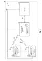
図1は、開示のセンサーネットワーク10を示すブロック図である。センサーネットワーク10は、1つ又は複数のセンサーノード20(モートと呼ばれることもある)、データ集信装置22、及び、サーバー24を含む。センサーネットワーク10は、センサーノード20によって収集されたデータをサーバー24に送信するための2つの異なる通信プロトコルを含む、ハイブリッドのネットワークである。具体的には、以下に詳しく説明するように、センサーネットワーク10は、無線ネットワーク又は電力線通信のいずれかを用いて、センサーノード20によって収集されたデータを伝達するための安定且つフレキシブルなネットワークを提供する。また、以下により詳しく説明するように、ネットワークのうちの一方が利用できない場合、センサーネットワーク10は、データ通信サービスが中断しないよう、容易にもう一方のネットワークに切り替わる。 FIG. 1 is a block diagram showing the disclosed
図1に示した実施形態において、センサーネットワーク10は、航空機26の一部である。ただし、センサーネットワーク10は、航空機26に限定されず、例えば、自動車などの他の環境でも使用することもできる。航空機26は、開示の性質上限定されるものではないが、航空機ネットワークは、一般的に、比較的速いデータ伝送速度を必要としない。従って、以下に説明するように、無線媒体ならびに電力線通信は、それぞれ、比較的低いデータ伝送速度を有する通信プロトコルに基づくものとすることができる。 In the embodiment shown in FIG. 1, the
センサーノード20のぞれぞれは、アンテナ30を含み、各センサーノード20は、無線接続32を介して、残りのセンサーノード20並びにデータ集信装置22と通信することができる。無線接続32は、例えば、無線周波数(RF)通信プロトコルに基づくものである。一実施形態において、無線接続32は、一秒あたり数百キロバイトのオーダーの比較的低いデータ伝送速度を有するRF通信プロトコルに基づくものであってよい。比較的低いデータ速度を有するRF通信プロトコルの一例は、IEEE(the Institute of Electrical and Electronics Engineers)802.15.4プロトコルに基づく通信プロトコルである。なお、IEEE802.15.4プロトコルは、7層OSI(オープンシステムインターコネクション:Open Systems Interconnect)モデルのうちの、物理(PHY)層やメディアアクセス制御(MAC)層などの、下位のネットワーク層を規定するのみである。PHY層は、第1層と呼ばれることがあり、ネットワーク層における最下層である。MAC層は、第2層と呼ばれることがある。なお、上位の層は、IEEE802.15.4プロトコルによって規定されない。IEEE802.15.4プロトコルに基づく無線通信プロトコルの例は、ZigBee(登録商標)、WirelessHART(登録商標)、および6LoWPANを含むが、これらに限定されない。 Each of the
各センサーノード20は、電力線通信38を介して、センサーノード同士の通信、並びに、データ集信装置22及びサーバー24との通信が可能である。また、電力線通信38は、例えば狭帯域電力線通信などの比較的低いデータ伝送速度を有する通信プロトコルに基づいたものであってよい。非限定的な一実施形態において、電力線通信38は、IEEE1901.2プロトコルに基づくものであってもよい。なお、狭帯域電力線通信は、典型的には、約500キロヘルツ(kHz)未満の周波数帯域で動作する。なお、電力線通信38は、狭帯域電力線通信のみに限定されるべきではないが、狭帯域通信では、航空機26に設けられた他のシステムとの干渉が低減される。また、一実施形態において、電力線通信38は、航空機26内の既存の交流(AC)又は直流(DC)の電力線のいずれかを用いることができ、これは、ひいては、航空機26の費用及び重量の低減につながる。具体的には、例えば、電力線通信38は、航空機26内の既存の115VのACライン、又は既存の28VのDCラインを使用することができる。 Each
センサーノード20は、例えば温度、圧力、速度、高度などの航空機26内の動作状況を示す検出情報を収集するための1つ又は複数のセンサー(図示せず)を含みうる。また、センサーノード20は、センサーによって収集された検出情報を、それぞれの制御モジュール40によって処理することができる。制御モジュール40は、特定用途向け集積回路(ASIC)、電子回路、組合せ論理回路、フィールドプログラマブルゲートアレイ(FPGA)、若しくは、コードを実行するハードウェアもしくはソフトウェアを含むプロセッサ(共有、専用、もしくはグループ)であるか、その一部であってよく、或いは、システム・オン・チップのように、これら要素のいくつか又はすべてを組み合わせたものであるか、若しくはその組合せの一部であってもよい。制御モジュール40は、無線接続32及び電力線通信38による両方の通信用にメモリに保存された複数のスタック構成を含み、これについては、以下により詳しく説明するとともに、図3に示している。センサーノード20は、センサーによって検出された動作状況を示すデータを、無線接続32又は電力線通信38のいずれかを介して、センサーネットワーク10内の他のセンサーノード20ならびにデータ集信装置22に送信することができる。 The
データ集信装置22は、アンテナ42を含む。無線接続32は、それぞれのアンテナ30、42を介して、センサーノード20をデータ集信装置22に接続する。データ集信装置22は、センサーノード20からデータを収集し、センサーノード20から受信したデータを、データ接続44によってサーバー24に送信することができる。接続44は、例えばイーサネット接続など、データを送信するための任意のタイプの接続であってよい。データ集信装置22は、センサーノード20から受信したデータをサーバー24に送信するための少なくとも1つの制御モジュール50を含む。制御モジュール50は、無線接続32及び電力線通信38による両方の通信用にメモリに保存された複数のスタック構成を含み、これについては、以下により詳しく説明するとともに、図3に示している。制御モジュール40及び制御モジュール50のいずれもが、無線接続32又は電力線通信38のいずれかに基づく通信を選択するための制御ロジックを含む。 The
図2は、インターフェイス64を介して2つのトランシーバー60、62と通信する制御モジュール50のブロック図である。具体的には、トランシーバーのうちの一方は、無線接続32(図1)と通信するRFトランシーバー60である。RFトランシーバー60は、無線接続32を介する送受信を行うためのものである。もう一方のトランシーバー62は、電力線通信38(図1)のための電力線通信(PLC)トランシーバーである。PLCトランシーバー62は、電力線通信38を介する送受信を行うためのものである。 FIG. 2 is a block diagram of a
RFトランシーバー60とPLCトランシーバー62の両方が、インターフェイス64と通信する。インターフェイス64は、例えば、IEEE802.15.4プロトコルに基づいたエンハンスト(enhanced)・シリアル周辺装置インターフェイス(serial peripheral interface: SPI)であってもよい。なお、SPIインターフェイスは、RFトランシーバー60及びPLCトランシーバー62の両方に共通である。インターフェイス64は、RFトランシーバー60及びPLCトランシーバー62からの通信を制御モジュール50に送信することができる。 Both the
図3は、制御モジュール50(図1及び図2)のメモリならびに制御モジュール40(図1に示す)のメモリに保存された、例示的なネットワークスタック構成70を示す。具体的には、スタック70は、第1の電力線通信スタック71、及び、第2の無線接続スタック80を含む。電力線通信スタック71は、図2に示したPLCトランシーバー62と通信するための1つ又は複数のスタックオプションを含む。図示した例示的な実施形態においては、電力線通信スタック71は、それぞれがOSIモデルに基づく2つのスタック71a、71bを含む。ただし、この図示例は、限定的なものではなく、別の実施形態においては、ネットワークスタック構成70は、Zigbee Stack(登録商標)など、別のプロトコルに基づくものであってもよい。 FIG. 3 shows an exemplary
図3は、複数の層、すなわち、PHY層72a、MAC層74a、ネットワーク層76a、及び、トランスポート層78aを含む、電力線通信スタック71aを示している。同様に、PHY層72b、MAC層74b、ネットワーク層76b、及び、トランスポート層78bを含む電力線通信スタック71bも示している。なお、簡潔化及び明確化のために、2つのスタック71a、71bにおける上位の3層、すなわち、セッション層、プレゼンテーション層、及び、アプリケーション層は、図3に示していない。しかし、電力線通信スタック71a、71bは、いずれも、これらの層を含む。 FIG. 3 shows a power
当業者であれば容易に理解するように、PHY層72a、72bは、物理的媒体に対するメッセージの送受信を行うことができる。ネットワークスタック構成70が制御モジュール40のメモリに保存されている場合、物理的媒体は、図1に示したセンサーノード20のセンサーモジュール(図示せず)でありうる。これに代えて、ネットワークスタック構成70が制御モジュール50のメモリに保存されている場合、物理的媒体は、PLCトランシーバー62(図2)でありうる。MAC層74a、74bは、ネットワーク層76a、76bとPHY層72a、72bの間のインターフェイスの役割を行うことができる。図3に示すように、MAC層74a、74bは、いずれも、IEEE802.15.4プロトコルに適合している。なお、IEEE802.15.4プロトコルは、電力線通信用に意図されていない。従って、MAC層74a、74bは、電力線通信用に適合又は改変されている。PLCトランシーバー62からのデータが、各PHY層72a、72bから上方に、スタックを通ってアプリケーション層(図示せず)まで進行するため、ネットワーク層76b、76b及びトランスポート層78a、78bは、PHY層72及びMAC層74よりも上位の層と考えることができる。ネットワークスタック構成70が制御モジュール40のメモリに保存されている場合、データは、次に、電力線通信38を介して送信される。ネットワークスタック構成70が制御モジュール50のメモリに保存されている場合、データは、次に、接続44を介して、サーバー24(図1)に送信される。 As those skilled in the art will easily understand, the PHY layers 72a and 72b can send and receive messages to and from a physical medium. When the
例示的な実施形態において、図3に示すように、ネットワーク層76aは、6LoWPANプロトコルに基づく通信に用いることができる。具体的には、ネットワーク層76aは、インターネットプロトコル バージョン6(IPv6)に基づいてデータパケットをトランスポート層78aに送信することができる。同様に、ネットワーク層76bは、インターネットプロトコル バージョン4(IPv4)に基づく通信に用いることができる。ネットワーク層76bは、ユーザーデータグラム プロトコル(UDP)に基づいてデータパケットをトランスポート層78bに送信することができる。なお、図3は、開示の性質上単なる例示であり、ネットワーク層76a、76b及びトランスポート層78a、78bは、別のプロトコルに基づくものであってもよい。なお、電力線通信スタック71は、2つのスタック71a、71bを含むが、これは開示の性質上単なる例示であり、他のタイプの通信プロトコルを包含する任意の数のスタックも含まれうる。 In an exemplary embodiment, as shown in FIG. 3, the
引き続き図3を参照すると、無線接続スタック80は、図2に示したRFトランシーバー60と通信するための1つ又は複数のスタックオプションを含む。図示の実施形態において、無線接続スタック80は、2つのスタック80a、80bを含む。具体的には、図3は、PHY層82a、MAC層84a、ネットワーク層86a、及び、トランスポート層88aを含む、無線接続スタック80aを示している。同様に、図3は、PHY層82b、MAC層84b、ネットワーク層86b、及び、トランスポート層88bを含む、無線接続スタック80bを示している。なお、簡潔化及び明確化のために、2つのスタック80a、80bにおける上位の3層、すなわち、セッション層、プレゼンテーション層、及び、アプリケーション層は、図3に示していない。 Continuing with reference to FIG. 3, the
PHY層82a、82bは、物理的装置に対するメッセージの送受信を行うことができる。ネットワークスタック構成80が制御モジュール40のメモリに保存されている場合、物理的装置は、図1に示したセンサーノード20のセンサー(図示せず)でありうる。これに代えて、ネットワークスタック構成80が制御モジュール50のメモリに保存されている場合、物理的装置は、RFトランシーバー60(図2)でありうる。電力線スタック71aのネットワーク層76aと同様に、無線接続スタック80aのネットワーク層86aは、6LoWPANに基づく通信に用いることができる。同様に、無線接続スタック80bのネットワーク層86bは、IPv4に基づくものとすることができる。 The PHY layers 82a and 82b can send and receive messages to and from the physical device. When the
図1及び図3を参照すると、制御モジュール40、50のそれぞれが、ネットワークスタック構成70の電力線通信スタック71又は無線接続スタック80のいずれかを選択するための制御ロジックを含みうる。特定のスタックの選択は、センサーネットワーク10の少なくとも1つの動作パラメータに基づいて行われうる。具体的には、特定のスタックの選択は、ネットワークスタック構成70の1つ又は複数の層(すなわち、PHY層、MAC層、ネットワーク層、トランスポート層、セッション層、プレゼンテーション層、及び、アプリケーション層)が利用不可能であるかどうかに基づいて行われうる。なお、一実施形態において、無線接続32(図1)が利用不可能な場合や、無線ネットワークを介した送信に適さない機密性の高いデータをセンサーネットワーク10(図1)上で伝達する場合を除いて使用されるデフォルトのスタックとして、無線接続スタック80を設定してもよい。例えば、無線接続スタック80のPHY層82a、82bに影響するジャミング(jamming)又は他のチャネル障害が存在するという通信を制御モジュール50が受信した場合、或いは制御モジュールがそのように判定した場合、制御モジュール50は、データ送信用に電力線通信スタック71を選択するであろう。 Referring to FIGS. 1 and 3, each of the
1つのアプローチにおいて、PHY層72a、72b、82a、82bの利用の可否に基づいて、制御モジュール40、50が、ネットワークスタック構成70のうちの電力線通信スタック71又は無線接続スタック80のいずれかを選択した後、制御モジュール40、50は、電力線通信スタック71又は無線接続スタック80のいずれかにおける特定のスタックを選択する。特定のスタックの選択は、スタックの上位層によって規定された通信プロトコルに基づいて行われうる。なお、上位層は、MAC層の上の5つの層(すなわち、ネットワーク層、トランスポート層、セッション層、プレゼンテーション層、及びアプリケーション層)を含む。例えば、センサーネットワーク10(図1)が音声データを送信しているという通信を制御モジュール40、50が受信した場合、或いは制御モジュールがそのように判定した場合、トランスポート層によって規定されるUDPが使用されうる。従って、電力線通信スタック71が既に選択されている場合、制御モジュール50によって電力線通信スタック71bが選択される。同様に、無線接続スタック80が既に選択されている場合、制御モジュール50によって無線接続スタック80bが選択される。 In one approach, the
なお、制御モジュール40(図1)は、ネットワークスタック構成70内のスタックのうちの1つを選択するための、制御モジュール50と同様の制御ロジックを含む。ただし、制御モジュール50は、例えばネットワーク形成及びセキュリティキー管理などの、様々な関連するセンサノード20を調整するために追加の機能を備えていてもよい。 The control module 40 (FIG. 1) includes the same control logic as the
図面を概括的に参照すると、開示されたセンサーネットワーク10は、通信のための無線接続ならびに電力線通信の両方を含むハイブリッドのネットワークを提供する。なお、電力線通信は、航空機26内の既存のAC又はDCの電力線のいずれかを用いることができ、これによって、有線接続に関連する費用及び重量が低減される。なお、特定のネットワークスタックを選択するための開示のアプローチは、制御モジュール40、50内の既存のハードウェアを使用する。最後に、航空機の電力システムは、負荷及び信号伝搬環境などの固有の課題を含んでいる。従って、狭帯域電力線通信を使用することが特に有利であり、これによれば航空機に設けられた他のシステムとの干渉が低減される。 With reference to the drawings in general, the disclosed
また、本開示は、以下の付記による実施形態を含む。 The present disclosure also includes embodiments according to the following appendices.
付記1.無線通信プロトコルに基づく第1のネットワークと、
電力線通信プロトコルに基づく第2のネットワークと、
前記第1のネットワーク及び前記第2のネットワークのうちの一方と通信する少なくとも1つのセンサーノードと、を含むセンサーネットワークであって、
前記少なくとも1つのセンサーノードは、少なくとも1つのセンサー、及び、前記少なくとも1つのセンサーと通信する制御モジュールを含み、前記制御モジュールは、前記センサーネットワークの少なくとも1つの動作パラメータに基づいて、前記第1のネットワーク及び前記第2のネットワークのうちの一方を選択するための制御ロジックを含む、センサーネットワーク。
A second network based on the power line communication protocol,
A sensor network comprising at least one sensor node communicating with one of the first network and the second network.
The at least one sensor node includes at least one sensor and a control module that communicates with the at least one sensor, wherein the control module is based on at least one operating parameter of the sensor network. A sensor network that includes a network and control logic for selecting one of the second networks.
付記2.前記制御モジュールは、メモリを含み、前記制御モジュールの前記メモリには、ネットワークスタック構成が保存されている、付記1に記載のセンサーネットワーク。 Appendix 2. The sensor network according to
付記3.前記ネットワークスタック構成は、前記無線通信プロトコルに基づく少なくとも1つの無線スタック、及び、前記電力線通信プロトコルに基づく少なくとも1つの電力線スタックを含む、付記2に記載のセンサーネットワーク。 Appendix 3. The sensor network according to Appendix 2, wherein the network stack configuration includes at least one wireless stack based on the wireless communication protocol and at least one power line stack based on the power line communication protocol.
付記4.前記少なくとも1つの無線スタック及び前記少なくとも1つの電力線スタックは、いずれも、7層オープンシステムインターコネクション(OSI)モデルに基づいており、前記少なくとも1つの無線スタック及び前記少なくとも1つの電力線スタックは、それぞれが複数の層を含む、付記3に記載のセンサーネットワーク。
付記5.前記少なくとも1つの動作パラメータは、前記少なくとも1つの無線スタック又は前記少なくとも1つの電力線スタックの前記複数の層のうちの特定の層が利用不可能かどうかに基づく、付記4に記載のセンサーネットワーク。
付記6.前記少なくとも1つの動作パラメータは、前記少なくとも1つの無線スタック又は前記少なくとも1つの電力線スタックの物理(PHY)層が利用不可能かどうかに基づく、付記4に記載のセンサーネットワーク。 Appendix 6. The sensor network according to
付記7.前記少なくとも1つの動作パラメータは、前記少なくとも1つの無線スタック又は前記少なくとも1つの電力線スタックにおける上位の層に基づく、付記4に記載のセンサーネットワーク。 Appendix 7. The sensor network according to
付記8.前記無線通信プロトコルは、IEEE(Institute of Electrical and Electronics Engineers)802.15.4プロトコルに基づくものである、付記1に記載のセンサーネットワーク。
付記9.前記電力線通信プロトコルは、約500キロヘルツ(kHz)未満の周波数帯域で動作する狭帯域電力線通信である、付記1に記載のセンサーネットワーク。 Appendix 9. The sensor network according to
付記10.前記電力線通信は、航空機内の既存の交流(AC)電力線及び既存の直流(DC)電力線のうちの一方を用いる、付記1に記載のセンサーネットワーク。
付記11.前記第1のネットワーク及び前記第2のネットワークのうちの一方と通信するデータ集信装置を含み、前記データ集信装置は、第2の制御モジュールを含む、付記1に記載のセンサーネットワーク。 Appendix 11. The sensor network according to
付記12.前記第2の制御モジュールは、前記センサーネットワークの前記少なくとも1つの動作パラメータに基づいて、前記第1のネットワーク及び前記第2のネットワークのうちの一方を選択するための制御ロジックを含む、付記11に記載のセンサーネットワーク。 Appendix 12. The second control module includes control logic for selecting one of the first network and the second network based on the at least one operating parameter of the sensor network, according to Appendix 11. Described sensor network.
付記13.前記第2の制御モジュールは、メモリを含み、前記制御モジュールの前記メモリには、ネットワークスタック構成が保存されている、付記11に記載のセンサーネットワーク。 Appendix 13. The sensor network according to Appendix 11, wherein the second control module includes a memory, and the memory of the control module stores a network stack configuration.
付記14.航空機のセンサーネットワーク内の第1のネットワーク及び第2のネットワークの一方を選択する方法であって、
制御モジュールによって、前記センサーネットワークの少なくとも1つの動作パラメータを検出することと、
前記制御モジュールによって、前記センサーネットワークの前記少なくとも1つの動作パラメータに基づいて、前記第1のネットワーク及び前記第2のネットワークのうちの一方を選択することと、を含み、
前記第1のネットワークは、無線通信プロトコルに基づくものであり、前記第2のネットワークは、電力線通信プロトコルに基づくものであり、前記制御モジュールは、前記第1のネットワーク及び前記第2のネットワークのうちの一方と通信する少なくとも1つのセンサーノードの一部である、方法。Appendix 14. A method of selecting one of the first network and the second network in the sensor network of an aircraft.
The control module detects at least one operating parameter of the sensor network.
The control module comprises selecting one of the first network and the second network based on the at least one operating parameter of the sensor network.
The first network is based on a wireless communication protocol, the second network is based on a power line communication protocol, and the control module is among the first network and the second network. A method that is part of at least one sensor node that communicates with one.
付記15.前記制御モジュールのメモリ内に保存されたネットワークスタック構成を提供することを含む、付記14に記載の方法。
付記16.前記ネットワークスタック構成内に、前記無線通信プロトコルに基づく少なくとも1つの無線スタックと、前記電力線通信プロトコルに基づく少なくとも1つの電力線スタックとを含む、付記15に記載の方法。 Appendix 16. 25. The method of
付記17.前記少なくとも1つの無線スタック及び前記少なくとも1つの電力線スタックは、いずれも、7層オープンシステムインターコネクション(OSI)モデルに基づいており、前記少なくとも1つの無線スタック及び前記少なくとも1つの電力線スタックは、いずれも、複数の層を含む、付記16に記載の方法。 Appendix 17. The at least one radio stack and the at least one power line stack are both based on a 7-layer open system interconnection (OSI) model, and the at least one radio stack and the at least one power line stack are both. , The method according to Appendix 16, comprising a plurality of layers.
付記18.前記第1のネットワーク及び前記第2のネットワークのうちの一方と通信するデータ集信装置を含み、前記データ集信装置は、第2の制御モジュールを含む、付記14に記載の方法。 Appendix 18. 14. The method of Appendix 14, comprising a data concentrator that communicates with one of the first network and the second network, wherein the data concentrator comprises a second control module.
付記19.前記第2の制御モジュールによって、前記センサーネットワークの前記少なくとも1つの動作パラメータに基づいて、前記第1のネットワーク及び前記第2のネットワークのうちの一方を選択することを含む、付記18に記載の方法。 Appendix 19. 18. The method of Addendum 18, comprising selecting one of the first network and the second network by the second control module based on the at least one operating parameter of the sensor network. ..
付記20.前記制御モジュールのメモリにネットワークスタック構成を保存することを含む、付記18に記載の方法。
本明細書に記載された装置及び方法の形態は、本開示の好ましい態様を構成するが、本開示は、装置及び方法のこれらの厳密な形態に限定されるものではなく、本開示の範囲から逸脱することなく変更が可能であるということを理解されたい。 Although the embodiments of the devices and methods described herein constitute preferred embodiments of the present disclosure, the present disclosure is not limited to these exact forms of the devices and methods, but within the scope of the present disclosure. Please understand that changes are possible without deviation.
Claims (10)
Translated fromJapaneseサーバーと、
前記サーバーに接続されたセンサーデータ集信装置と、
無線通信プロトコルに基づく第1のネットワークと、
前記センサーデータ集信装置と前記サーバーとに接続された電力線通信プロトコルに基づく第2のネットワークと、を含み、
前記センサーデータ集信装置は、前記電力線通信プロトコルに基づく少なくとも1つの電力線スタックと前記無線通信プロトコルに基づく少なくとも1つの無線スタックとを保存する第1のメモリを含む、第1の制御モジュールを有し、前記少なくとも1つの電力線スタックは第1のメディアアクセス制御(МAC)層を含み、前記少なくとも1つの無線スタックは第2のメディアアクセス制御(МAC)層を含み、前記第1のMAC層と前記第2のMAC層は両方前記無線通信プロトコルに適合しており、
前記センサーネットワークはさらに、前記第1のネットワーク及び前記第2のネットワークのうちの選択された一方を介して前記センサーデータ集信装置と通信し、前記第2のネットワークを介して前記サーバーと通信する少なくとも1つのセンサーノードと、を含み、
前記少なくとも1つのセンサーノードは、少なくとも1つのセンサー、及び、前記少なくとも1つのセンサーと通信する第2の制御モジュールを含み、前記第2の制御モジュールは、前記第1のネットワーク又は前記第2のネットワークを選択し、前記第1のネットワークと前記第2のネットワークとを介して前記センサーデータ集信装置と通信し、前記第2のネットワークを介して前記サーバーと通信するための制御ロジックを含み、前記第1の制御モジュール及び前記第2の制御モジュールによる前記第1のネットワーク又は前記第2のネットワークの選択は前記センサーネットワークの少なくとも1つの動作パラメータに基づいており、前記第1のネットワークは、前記第1の制御モジュール又は前記第2の制御モジュールが機密データを送るのでない限り使用されるデフォルトの接続である、センサーネットワーク。A sensor network that selects either a wireless connection or a wired connection.
With the server
The sensor data collector connected to the server and
The first network based on the wireless communication protocol and
Includes a second network based on a power line communication protocol connected to the sensor data collector and the server.
The sensor data collector has a first control module including a first memory for storing at least one power line stack based on the power line communication protocol and at least one radio stack based on the radio communication protocol. The at least one power line stack includes a first media access control (МAC) layer, the at least one radio stack includes a second media access control (МAC) layer, the first MAC layer and the first. Both MAC layers of 2 are compatible with the wireless communication protocol.
The sensor network further communicates with the sensor data collector viaa selected one of the first network and the second network, and communicates with the server via the second network. Including at least one sensor node,
The at least one sensor node includes at least one sensor and a second control module that communicates with the at least one sensor, wherein the second control module is the first network or the second network. The control logic for communicating with the sensor data collector via the first network and the second network and communicating with the server via the second network is included. The selection of the first network or the second network by the first control module and the second control module is based on at least one operating parameter of the sensor network, wherein the first network is the first. A sensor network, which is the default connection used unless one control module or the second control module sends sensitive data.
前記センサーノード内の第1の制御モジュールによって、前記センサーネットワークの少なくとも1つの動作パラメータを検出し、この際に、前記第1のネットワークは、前記制御モジュールが機密データを送るのでない限り使用されるデフォルトの接続であり、前記デフォルトの接続においては、前記第1の制御モジュールが、電力線通信プロトコルに基づく少なくとも1つの電力線スタックと無線通信プロトコルに基づく少なくとも1つの無線スタックとを保存するメモリを含み、前記少なくとも1つの電力線スタックは第1のメディアアクセス制御(МAC)層を含み、前記少なくとも1つの無線スタックは第2のメディアアクセス制御(МAC)層を含み、前記第1のMAC層及び前記第2のMAC層は両方とも前記無線通信プロトコルに適合していることと、
前記第1の制御モジュールによって、前記センサーネットワークの前記少なくとも1つの動作パラメータに基づいて、前記第1のネットワーク又は前記第2のネットワークを選択することと、を含み、
前記センサーノードは、前記無線通信プロトコルに基づく前記第1のネットワークを介して前記センサーデータ集信装置と通信し、前記センサーノードは、前記電力線通信プロトコルに基づく前記第2のネットワークを介して前記センサーデータ集信装置及び前記サーバーと通信し、前記第1の制御モジュールは、前記第1のネットワーク及び前記第2のネットワークと通信する少なくとも1つのセンサーノードの一部である、方法。
A method of selecting one of a first network and a second network in the sensor network of an aircraft, wherein the first network is a wireless communication protocol network connected between a sensor node and a sensor data collector. The second network is a power line communication protocol network connected between the sensor node and the sensor data collector, and between the sensor node and the server.
A first control module within the sensornode detects at least one operating parameter of the sensor network, wherein the first network is used unless the control module sends sensitive data. A default connection, wherein in the default connection, the first control module comprises a memory for storing at least one power line stack based on the power line communication protocol and at least one radio stack based on the radio communication protocol. The at least one power line stack includes a first media access control (МAC) layer, the at least one radio stack includes a second media access control (МAC) layer, the first MAC layer and the second. Both MAC layers are compliant with the wireless communication protocol.
The first control module comprises selecting the first network or the second network based on the at least one operating parameter of the sensor network.
The sensor node communicates with the sensor data collector via the first network based on the wireless communication protocol, and the sensor node communicates with the sensor via the second network based on the power line communication protocol. A method of communicating with a data collector and said server, wherein the first control module is part of at least one sensor node communicating with said first network and said second network.
Applications Claiming Priority (2)
| Application Number | Priority Date | Filing Date | Title |
|---|---|---|---|
| US14/809,829 | 2015-07-27 | ||
| US14/809,829US10057388B2 (en) | 2015-07-27 | 2015-07-27 | System and method for selecting a communication network in a sensor network |
Publications (2)
| Publication Number | Publication Date |
|---|---|
| JP2017028691A JP2017028691A (en) | 2017-02-02 |
| JP7018700B2true JP7018700B2 (en) | 2022-02-14 |
Family
ID=56131379
Family Applications (1)
| Application Number | Title | Priority Date | Filing Date |
|---|---|---|---|
| JP2016140329AActiveJP7018700B2 (en) | 2015-07-27 | 2016-07-15 | Systems and methods for selecting communication networks within sensor networks |
Country Status (4)
| Country | Link |
|---|---|
| US (1) | US10057388B2 (en) |
| EP (1) | EP3125614B1 (en) |
| JP (1) | JP7018700B2 (en) |
| CN (1) | CN106411362B (en) |
Families Citing this family (12)
| Publication number | Priority date | Publication date | Assignee | Title |
|---|---|---|---|---|
| US11900090B2 (en) | 2015-10-27 | 2024-02-13 | Airwatch Llc | Enforcement of updates for devices unassociated with a directory service |
| US10860304B2 (en)* | 2015-10-27 | 2020-12-08 | Airwatch Llc | Enforcement of updates for devices unassociated with a directory service |
| US9986411B1 (en) | 2016-03-09 | 2018-05-29 | Senseware, Inc. | System, method and apparatus for node selection of a sensor network |
| CN107276987A (en)* | 2017-05-17 | 2017-10-20 | 厦门奥普拓自控科技有限公司 | A kind of the special line physical isolation industrial data means of communication and system |
| FR3069680B1 (en)* | 2017-07-25 | 2019-09-20 | Airbus Operations | DEVICE MANAGING INTERFACES IN AN AIRCRAFT |
| US11510097B2 (en) | 2017-11-16 | 2022-11-22 | Distech Controls Inc. | Environment control device and method for inferring an optimal wireless data transfer rate using a neural network |
| US10616121B2 (en)* | 2017-11-16 | 2020-04-07 | Distech Controls Inc. | Inference server and environment control device for inferring an optimal wireless data transfer rate |
| CN109728953A (en)* | 2018-12-30 | 2019-05-07 | 联想(北京)有限公司 | A kind of configuration device and method |
| CN112436868B (en)* | 2020-11-24 | 2022-11-11 | 国网江苏省电力有限公司 | Method and system for transmitting multiplexing data of distributed photovoltaic power channels |
| US12192101B2 (en)* | 2020-12-04 | 2025-01-07 | The Boeing Company | Secure data connections in low data rate networks |
| NO347347B1 (en)* | 2021-11-09 | 2023-09-25 | Dimeq As | Adaptable Communication System for a Vessel |
| CN116208193B (en)* | 2021-12-01 | 2024-02-06 | 杭州联芯通半导体有限公司 | Method for wireless channel frequency hopping synchronization in PLC and RF integrated network |
Citations (6)
| Publication number | Priority date | Publication date | Assignee | Title |
|---|---|---|---|---|
| JP2011114443A (en) | 2009-11-25 | 2011-06-09 | Hitachi Ltd | Communication device and watt-hour meter |
| JP2011244388A (en) | 2010-05-21 | 2011-12-01 | Sharp Corp | Wired communication system and terminator used for the same |
| JP2012195936A (en) | 2011-03-09 | 2012-10-11 | General Electric Co <Ge> | System, method, and apparatus for reducing network congestion in smart utility meter |
| JP2014172607A (en) | 2013-03-05 | 2014-09-22 | Boeing Co | Aircraft data transmission modules |
| JP2015502711A (en) | 2011-11-21 | 2015-01-22 | クゥアルコム・インコーポレイテッドQualcomm Incorporated | Hybrid networking system with seamless path switching of streams |
| JP2015115646A (en) | 2013-12-09 | 2015-06-22 | パナソニックIpマネジメント株式会社 | Meter reading device, management device, communication method, program, and communication system |
Family Cites Families (23)
| Publication number | Priority date | Publication date | Assignee | Title |
|---|---|---|---|---|
| US6563418B1 (en) | 2000-12-08 | 2003-05-13 | Cisco Technology, Inc. | Automotive network and adapter |
| US7069312B2 (en)* | 2002-12-06 | 2006-06-27 | Microsoft Corporation | Network location signature for disambiguating multicast messages in dual-IP stack and/or multi-homed network environments |
| KR100559026B1 (en)* | 2003-05-30 | 2006-03-10 | 엘지전자 주식회사 | Home network system |
| US7289887B2 (en)* | 2003-09-08 | 2007-10-30 | Smartsynch, Inc. | Systems and methods for remote power management using IEEE 802 based wireless communication links |
| US7965673B2 (en)* | 2003-09-09 | 2011-06-21 | Sony Corporation | System and method for multi-link communication in home network |
| WO2005032158A2 (en)* | 2003-09-23 | 2005-04-07 | Arkados, Inc. | Integrated universal network adapter |
| US20050085259A1 (en)* | 2003-10-15 | 2005-04-21 | Conner W. S. | Technique to coordinate wireless network over a power line or other wired back channel |
| US7904578B1 (en)* | 2003-10-30 | 2011-03-08 | At&T Intellectual Property I, L.P. | Bandwidth and topology management device for home networks |
| US7719416B2 (en)* | 2005-09-09 | 2010-05-18 | Microstrain, Inc. | Energy harvesting, wireless structural health monitoring system |
| GB0922091D0 (en)* | 2009-12-17 | 2010-02-03 | Gigle Networks Ltd | Communications apparatus |
| US8188855B2 (en)* | 2008-11-06 | 2012-05-29 | Current Technologies International Gmbh | System, device and method for communicating over power lines |
| CN101437308B (en)* | 2008-12-23 | 2010-06-02 | 南京航空航天大学 | Self-healing wireless strain sensor network system and its implementation method |
| US20120223840A1 (en)* | 2009-06-05 | 2012-09-06 | Leviton Manufacturing Co., In. | Smart grid over power line communication network |
| CN103238305A (en)* | 2010-05-28 | 2013-08-07 | 安全第一公司 | Accelerator system for use with secure data storage |
| EP2617150B1 (en)* | 2010-09-14 | 2020-07-01 | Sony Corporation | Communication device using spatial diversity, communications system and method |
| US8836467B1 (en)* | 2010-09-28 | 2014-09-16 | Icontrol Networks, Inc. | Method, system and apparatus for automated reporting of account and sensor zone information to a central station |
| WO2012069950A1 (en)* | 2010-11-25 | 2012-05-31 | Koninklijke Philips Electronics N.V. | System and method for optimizing data transmission to nodes of a wireless mesh network |
| US20120218120A1 (en)* | 2011-02-24 | 2012-08-30 | General Electric Company | Meter processing communication system |
| US8799510B2 (en)* | 2011-07-05 | 2014-08-05 | Cisco Technology, Inc. | Managing host routes for local computer networks with a plurality of field area routers |
| KR101304426B1 (en) | 2011-12-08 | 2013-09-05 | 주식회사 넥스트컨버젼스그룹 | Ship system using Power Line Communication |
| US20130201316A1 (en)* | 2012-01-09 | 2013-08-08 | May Patents Ltd. | System and method for server based control |
| US9191209B2 (en)* | 2013-06-25 | 2015-11-17 | Google Inc. | Efficient communication for devices of a home network |
| CN203938304U (en)* | 2014-04-30 | 2014-11-12 | 湖北和航科技发展有限公司 | A kind of elevator long distance supervisory systems that adopts power line carrier communication |
- 2015
- 2015-07-27USUS14/809,829patent/US10057388B2/enactiveActive
- 2016
- 2016-06-10EPEP16174010.5Apatent/EP3125614B1/enactiveActive
- 2016-07-15JPJP2016140329Apatent/JP7018700B2/enactiveActive
- 2016-07-25CNCN201610590592.6Apatent/CN106411362B/enactiveActive
Patent Citations (6)
| Publication number | Priority date | Publication date | Assignee | Title |
|---|---|---|---|---|
| JP2011114443A (en) | 2009-11-25 | 2011-06-09 | Hitachi Ltd | Communication device and watt-hour meter |
| JP2011244388A (en) | 2010-05-21 | 2011-12-01 | Sharp Corp | Wired communication system and terminator used for the same |
| JP2012195936A (en) | 2011-03-09 | 2012-10-11 | General Electric Co <Ge> | System, method, and apparatus for reducing network congestion in smart utility meter |
| JP2015502711A (en) | 2011-11-21 | 2015-01-22 | クゥアルコム・インコーポレイテッドQualcomm Incorporated | Hybrid networking system with seamless path switching of streams |
| JP2014172607A (en) | 2013-03-05 | 2014-09-22 | Boeing Co | Aircraft data transmission modules |
| JP2015115646A (en) | 2013-12-09 | 2015-06-22 | パナソニックIpマネジメント株式会社 | Meter reading device, management device, communication method, program, and communication system |
Non-Patent Citations (1)
| Title |
|---|
| RF Sensor Node Development Platform for 6LoWPAN and 2.4 GHz Applications,TI Designs,米国,Texas Instruments,2014年03月,page 1-27 |
Also Published As
| Publication number | Publication date |
|---|---|
| JP2017028691A (en) | 2017-02-02 |
| EP3125614B1 (en) | 2021-04-21 |
| CN106411362A (en) | 2017-02-15 |
| US20170034316A1 (en) | 2017-02-02 |
| EP3125614A1 (en) | 2017-02-01 |
| US10057388B2 (en) | 2018-08-21 |
| CN106411362B (en) | 2021-06-25 |
Similar Documents
| Publication | Publication Date | Title |
|---|---|---|
| JP7018700B2 (en) | Systems and methods for selecting communication networks within sensor networks | |
| US8570922B2 (en) | Efficient addressing in wireless hart protocol | |
| CN101682541B (en) | Method and apparatus for routing packets over a network using a directed graph | |
| US11509580B2 (en) | Partial source routing for cross-network routing | |
| US7167081B2 (en) | Communication module and process for networking within and between powered communication devices over a multi-phase power distribution system or subsystem | |
| EP2381619B1 (en) | System and method for unique identifier exchange during auto-negotiatiom | |
| US20080274766A1 (en) | Combined Wired and Wireless Communications with Field Devices in a Process Control Environment | |
| US12362965B2 (en) | Relay device, vehicle, communication method, and communication program | |
| US12266225B2 (en) | On-vehicle communication system, switch device, communication control method, and communication control program | |
| CN112615806B (en) | Communication device and communication method | |
| EP3796596B1 (en) | Bidirectional forwarding detection control packet to indicate maintenance mode operation | |
| CN112470487B (en) | Method and apparatus for remote monitoring and diagnostics of field devices | |
| EP2573983A2 (en) | Network system and method for determining network path | |
| US12135663B2 (en) | Method, equipment, communication program, on-board device having these equipments | |
| EP3427539B1 (en) | Three-address scheme for forwarding frames in a wireless mesh network | |
| Siddikov et al. | Data Transfer Methods and Algorithms in Wireless Sensor Networks for IoT-based Remote Monitoring System of Hybrid Energy Supply Sources | |
| Makashov et al. | Anti-jamming Wireless Sensor Network Model | |
| EP1758306B1 (en) | Method and device for transmitting a control signal of a resilient packet ring media access control | |
| JP2014165829A (en) | Radio communication device | |
| CN116886465A (en) | Automatic routing method, device and system of gateway and Modbus gateway | |
| CN116805915A (en) | Ethernet devices, data transmission methods, devices, equipment, media and vehicles | |
| Chau et al. | Efficient and robust data collection using compact micro hardware, distributed bus architectures and optimizing software | |
| Estremote et al. | Development of heterogeneous node network using microcontroller with protocols CAN and Zigbee | |
| HK1163977B (en) | System and method for network management in the link between the network devices |
Legal Events
| Date | Code | Title | Description |
|---|---|---|---|
| A621 | Written request for application examination | Free format text:JAPANESE INTERMEDIATE CODE: A621 Effective date:20190708 | |
| A977 | Report on retrieval | Free format text:JAPANESE INTERMEDIATE CODE: A971007 Effective date:20200805 | |
| A131 | Notification of reasons for refusal | Free format text:JAPANESE INTERMEDIATE CODE: A131 Effective date:20200818 | |
| A521 | Request for written amendment filed | Free format text:JAPANESE INTERMEDIATE CODE: A523 Effective date:20201118 | |
| A131 | Notification of reasons for refusal | Free format text:JAPANESE INTERMEDIATE CODE: A131 Effective date:20210511 | |
| A521 | Request for written amendment filed | Free format text:JAPANESE INTERMEDIATE CODE: A523 Effective date:20210806 | |
| TRDD | Decision of grant or rejection written | ||
| A01 | Written decision to grant a patent or to grant a registration (utility model) | Free format text:JAPANESE INTERMEDIATE CODE: A01 Effective date:20220125 | |
| A61 | First payment of annual fees (during grant procedure) | Free format text:JAPANESE INTERMEDIATE CODE: A61 Effective date:20220201 | |
| R150 | Certificate of patent or registration of utility model | Ref document number:7018700 Country of ref document:JP Free format text:JAPANESE INTERMEDIATE CODE: R150 | |
| R250 | Receipt of annual fees | Free format text:JAPANESE INTERMEDIATE CODE: R250 |