JP7017851B2 - Fault diagnosis system and processing unit - Google Patents
Fault diagnosis system and processing unitDownload PDFInfo
- Publication number
- JP7017851B2 JP7017851B2JP2016234076AJP2016234076AJP7017851B2JP 7017851 B2JP7017851 B2JP 7017851B2JP 2016234076 AJP2016234076 AJP 2016234076AJP 2016234076 AJP2016234076 AJP 2016234076AJP 7017851 B2JP7017851 B2JP 7017851B2
- Authority
- JP
- Japan
- Prior art keywords
- processing
- diagnosis
- sensor
- unit
- processing mode
- Prior art date
- Legal status (The legal status is an assumption and is not a legal conclusion. Google has not performed a legal analysis and makes no representation as to the accuracy of the status listed.)
- Active
Links
- 238000012545processingMethods0.000titleclaimsdescription185
- 238000003745diagnosisMethods0.000titleclaimsdescription113
- 238000000034methodMethods0.000claimsdescription21
- 230000005856abnormalityEffects0.000claimsdescription19
- 230000008569processEffects0.000claimsdescription19
- 230000008859changeEffects0.000claimsdescription9
- 238000005070samplingMethods0.000description24
- 238000005259measurementMethods0.000description9
- 230000004048modificationEffects0.000description8
- 238000012986modificationMethods0.000description8
- 238000010586diagramMethods0.000description7
- 230000004043responsivenessEffects0.000description4
- 238000002474experimental methodMethods0.000description3
- 230000006870functionEffects0.000description3
- 230000004044responseEffects0.000description3
- XEEYBQQBJWHFJM-UHFFFAOYSA-NIronChemical compound[Fe]XEEYBQQBJWHFJM-UHFFFAOYSA-N0.000description2
- 238000004364calculation methodMethods0.000description2
- 238000002405diagnostic procedureMethods0.000description2
- 239000010687lubricating oilSubstances0.000description2
- 238000004590computer programMethods0.000description1
- 238000001514detection methodMethods0.000description1
- 230000000694effectsEffects0.000description1
- 230000014509gene expressionEffects0.000description1
- 230000010365information processingEffects0.000description1
- 239000000203mixtureSubstances0.000description1
- 238000000465mouldingMethods0.000description1
- 238000004088simulationMethods0.000description1
Images


Classifications
- G—PHYSICS
- G05—CONTROLLING; REGULATING
- G05B—CONTROL OR REGULATING SYSTEMS IN GENERAL; FUNCTIONAL ELEMENTS OF SUCH SYSTEMS; MONITORING OR TESTING ARRANGEMENTS FOR SUCH SYSTEMS OR ELEMENTS
- G05B19/00—Programme-control systems
- G05B19/02—Programme-control systems electric
- G05B19/04—Programme control other than numerical control, i.e. in sequence controllers or logic controllers
- G05B19/042—Programme control other than numerical control, i.e. in sequence controllers or logic controllers using digital processors
- B—PERFORMING OPERATIONS; TRANSPORTING
- B60—VEHICLES IN GENERAL
- B60W—CONJOINT CONTROL OF VEHICLE SUB-UNITS OF DIFFERENT TYPE OR DIFFERENT FUNCTION; CONTROL SYSTEMS SPECIALLY ADAPTED FOR HYBRID VEHICLES; ROAD VEHICLE DRIVE CONTROL SYSTEMS FOR PURPOSES NOT RELATED TO THE CONTROL OF A PARTICULAR SUB-UNIT
- B60W50/00—Details of control systems for road vehicle drive control not related to the control of a particular sub-unit, e.g. process diagnostic or vehicle driver interfaces
- B60W50/02—Ensuring safety in case of control system failures, e.g. by diagnosing, circumventing or fixing failures
- B60W50/0205—Diagnosing or detecting failures; Failure detection models
- G—PHYSICS
- G05—CONTROLLING; REGULATING
- G05B—CONTROL OR REGULATING SYSTEMS IN GENERAL; FUNCTIONAL ELEMENTS OF SUCH SYSTEMS; MONITORING OR TESTING ARRANGEMENTS FOR SUCH SYSTEMS OR ELEMENTS
- G05B23/00—Testing or monitoring of control systems or parts thereof
- G05B23/02—Electric testing or monitoring
- G—PHYSICS
- G07—CHECKING-DEVICES
- G07C—TIME OR ATTENDANCE REGISTERS; REGISTERING OR INDICATING THE WORKING OF MACHINES; GENERATING RANDOM NUMBERS; VOTING OR LOTTERY APPARATUS; ARRANGEMENTS, SYSTEMS OR APPARATUS FOR CHECKING NOT PROVIDED FOR ELSEWHERE
- G07C5/00—Registering or indicating the working of vehicles
- G07C5/08—Registering or indicating performance data other than driving, working, idle, or waiting time, with or without registering driving, working, idle or waiting time
- G07C5/0808—Diagnosing performance data
- G—PHYSICS
- G05—CONTROLLING; REGULATING
- G05B—CONTROL OR REGULATING SYSTEMS IN GENERAL; FUNCTIONAL ELEMENTS OF SUCH SYSTEMS; MONITORING OR TESTING ARRANGEMENTS FOR SUCH SYSTEMS OR ELEMENTS
- G05B2219/00—Program-control systems
- G05B2219/20—Pc systems
- G05B2219/26—Pc applications
- G05B2219/2637—Vehicle, car, auto, wheelchair
- G—PHYSICS
- G05—CONTROLLING; REGULATING
- G05B—CONTROL OR REGULATING SYSTEMS IN GENERAL; FUNCTIONAL ELEMENTS OF SUCH SYSTEMS; MONITORING OR TESTING ARRANGEMENTS FOR SUCH SYSTEMS OR ELEMENTS
- G05B2219/00—Program-control systems
- G05B2219/30—Nc systems
- G05B2219/37—Measurements
- G05B2219/37434—Measuring vibration of machine or workpiece or tool
Landscapes
- Engineering & Computer Science (AREA)
- Automation & Control Theory (AREA)
- Physics & Mathematics (AREA)
- General Physics & Mathematics (AREA)
- Human Computer Interaction (AREA)
- Transportation (AREA)
- Mechanical Engineering (AREA)
- Testing Of Devices, Machine Parts, Or Other Structures Thereof (AREA)
- Testing And Monitoring For Control Systems (AREA)
Description
Translated fromJapanese本発明は、故障診断システムに関する。 The present invention relates to a failure diagnosis system.
例えばモータ、ギヤモータ、ギヤボックスなどの機器の故障を検知するための故障診断システムが知られている。故障診断システムは、一般に、診断対象装置に配置されるセンサと、センサからの情報に基づいて診断対象装置に異常が発生しているか否かを判定する処理ユニットと、を備える。従来では、例えば特許文献1に記載されるような故障診断システムが提案されている。 For example, a failure diagnosis system for detecting a failure of a device such as a motor, a gear motor, or a gear box is known. The failure diagnosis system generally includes a sensor arranged in the diagnosis target device and a processing unit for determining whether or not an abnormality has occurred in the diagnosis target device based on information from the sensor. Conventionally, for example, a failure diagnosis system as described in Patent Document 1 has been proposed.
本発明のある態様の例示的な目的のひとつは、より利便性の高い故障診断システムを提供することにある。 One of the exemplary objects of an aspect of the present invention is to provide a more convenient failure diagnosis system.
本発明のある態様の故障診断システムは、複数の診断対象装置の各々に設けられ、対応する診断対象装置の診断対象情報を検知するセンサと、1台または複数台の診断対象装置に対して設けられ、センサにより検知された診断対象情報を処理する処理ユニットと、を備える。処理ユニットは、第1処理モードと、第1処理モードと異なる処理を行う第2処理モードとを実行可能であり、選択された処理モードにより診断対象情報を処理する。 The failure diagnosis system of a certain aspect of the present invention is provided in each of a plurality of diagnosis target devices, and is provided for a sensor for detecting the diagnosis target information of the corresponding diagnosis target device and one or more diagnosis target devices. It is provided with a processing unit that processes the diagnosis target information detected by the sensor. The processing unit can execute the first processing mode and the second processing mode that performs processing different from the first processing mode, and processes the diagnosis target information according to the selected processing mode.
なお、以上の構成要素の任意の組み合わせや、本発明の構成要素や表現を方法、装置、システムなどの間で相互に置換したものもまた、本発明の態様として有効である。 It should be noted that any combination of the above components and those in which the components and expressions of the present invention are mutually replaced between methods, devices, systems and the like are also effective as aspects of the present invention.
本発明によれば、より利便性の高い故障診断システムを提供できる。 According to the present invention, it is possible to provide a more convenient failure diagnosis system.
以下、各図面に示される同一または同等の構成要素、部材、工程には、同一の符号を付するものとし、適宜重複した説明は省略する。また、各図面における部材の寸法は、理解を容易にするために適宜拡大、縮小して示される。また、各図面において実施の形態を説明する上で重要ではない部材の一部は省略して表示する。 Hereinafter, the same or equivalent components, members, and processes shown in the drawings shall be designated by the same reference numerals, and redundant description thereof will be omitted as appropriate. Further, the dimensions of the members in each drawing are shown in an appropriately enlarged or reduced size for easy understanding. In addition, some of the members that are not important for explaining the embodiment in each drawing are omitted and displayed.
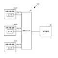
図1は、実施の形態に係る故障診断システム100の構成を示す模式図である。故障診断システム100は、ギヤモータ2で総称されるギヤモータ2a、2b、2cの異常を検知し、その解析を支援する。なお、故障診断システム100は、例えばモータ、ギヤボックス、エンジン、工作機械、成型機などのギヤモータ2以外の診断対象装置の異常を検知するのに用いられてもよい。 FIG. 1 is a schematic diagram showing a configuration of a
故障診断システム100は、センサ10で総称されるセンサ10a、10b、10cと、処理ユニット20と、端末装置30と、を備える。本実施の形態では、センサ10a、10b、10cはそれぞれ、処理ユニット20と有線で接続される。また、処理ユニット20は、端末装置30と有線または無線で接続される。なお、図1では、処理ユニット20に3つのセンサ10が接続される場合を示しているが、処理ユニット20のセンサ接続ポートのポート数の範囲内であれば、処理ユニット20に接続されるセンサ10の数は問わない。したがって、例えば、処理ユニット20にセンサ10が1つのみ接続されてもよい。 The
センサ10a、10b、10cはそれぞれ、ギヤモータ2a、2b、2cに取り付けられる。センサ10は、本実施の形態では振動センサであり、対応するギヤモータ2に生じている振動を検知し、振動の大きさを示す振動情報(診断対象情報)を生成して処理ユニット20に送信する。なお、図1では、各ギヤモータ2に1つのセンサ10が取り付けられる場合を示しているが、各ギヤモータ2に2つ以上のセンサ10が取り付けられてもよい。もちろん、一部のギヤモータ2にだけ2つ以上のセンサ10が取り付けられてもよい。また、ギヤモータ2におけるセンサ10の取付位置は、異常検知に適した位置を実験やシミュレーション等により定めればよい。 The
処理ユニット20は、各センサ10から送られた振動情報に対して所定の処理を実行する。本実施の形態では、処理ユニット20は、センサ10a、10b、10cから送られた振動情報に基づき、ギヤモータ2a、2b、2cに異常が発生しているか否かを判定する診断処理を繰り返し実行する。そして、処理ユニット20は、判定結果を端末装置30に送信する。 The
端末装置30は、ユーザが操作する情報処理装置である。端末装置30は、ギヤモータ2に異常が発生している否かを判定する診断処理に関する設定情報(以下、「診断設定情報」と呼ぶ)を入力するための入力画面(図4で後述)を表示させる。端末装置30は、入力画面に対して入力された診断設定情報を処理ユニット20へアップロードする。また、端末装置30は、処理ユニット20から送られた診断処理の判定結果を所定の表示部に表示する。ユーザは、表示部に表示された判定結果を確認することにより、ギヤモータ2に異常が発生したことを知ることができる。 The
図2は、処理ユニット20の機能および構成を示すブロック図である。ここに示す各ブロックは、ハードウェア的には、コンピュータのCPUやメモリをはじめとする素子や機械装置で実現でき、ソフトウェア的にはコンピュータプログラム等によって実現されるが、ここでは、それらの連携によって実現される機能ブロックを描いている。したがって、これらの機能ブロックはハードウェア、ソフトウェアの組合せによっていろいろなかたちで実現できることは、当業者には理解されるところである。以降のブロック図についても同様である。 FIG. 2 is a block diagram showing the functions and configurations of the
処理ユニット20は、診断処理を実行するデータ処理部40と、そのデータ処理のための各種データを記憶する記憶領域であるデータ保持部50と、を含む。 The
データ保持部50は、センサ情報保持部51と、設定情報保持部52と、を含む。センサ情報保持部51は、センサに関する情報を保持する。図3は、センサ情報保持部51のデータ構造図である。センサ情報保持部51は、センサ種別と、有効サンプリング周波数とを対応づけて保持する。センサ種別はセンサの種類を示し、有効サンプリング周波数はそのセンサに対する有効なサンプリング周波数の範囲を示す。高応答な種類のセンサほど、有効サンプリング周波数の上限値は高くなる。センサ情報保持部51には、例えば、処理ユニット20に接続される又は接続される可能性のあるセンサに関する情報を登録すればよい。 The
設定情報保持部52は、診断設定情報を保持する。診断設定情報は、後述する図4の入力画面で入力される各種設定情報であり、例えば、処理モード、サンプリング周波数等を含む。 The setting
データ処理部40は、入力画面提供部41と、入力情報取得部42と、診断対象情報取得部43と、診断結果提供部44と、処理時間特定部45と、入力情報チェック部46と、処理実行部47と、を含む。 The
入力画面提供部41は、端末装置30からアクセスを受け付け、診断設定情報の入力画面を端末装置30に送信して表示させる。図4は、診断設定情報の入力画面を示す。本実施の形態では、入力画面の各フィールドに設定情報が入力される度に、その内容が端末装置30から処理ユニット20にアップロードされる。 The input
接続センサ数フィールド61には、処理ユニット20に接続されるセンサ10の数を入力する。本実施の形態の処理ユニット20は、センサ10を接続するためのセンサ接続ポートを12個有するため、接続センサ数フィールド61には1~12の値を設定できる。タブ62(ポート1~ポート12)をクリックすると、対応するセンサ接続ポートに接続されるセンサ10に関する診断設定情報の入力画面に切り替わる。つまり、本実施の形態では、接続されるセンサ10ごとに、処理モード等の診断設定情報を設定できる。なお、タブ62は、実際にセンサ10が接続されているセンサ接続ポートのみ選択可能となる。 In the number of connected
センサ種別フィールド63では、センサ情報保持部51が保持するセンサ種別の中から、対応するセンサ10のセンサ種別を選択する。例えば、センサ情報保持部51が保持するデータが図3の状態の場合、センサ種別フィールド63ではセンサ種別「AAA」またはセンサ種別「BBB」を選択できる。 In the
処理モードフィールド64では、対応するセンサ10から取得される振動情報に対して実行する処理を示す処理モードを選択する。本実施の形態では、処理モードとして第1処理モードまたは第2処理モードを選択できる。第1処理モードおよび第2処理モードについては後述する。 In the
サンプリング周波数フィールド65には、センサ10から送られてくる振動情報を診断対象情報取得部43が取得する頻度が入力される。計測時間フィールド66には、1回の診断処理で診断対象情報取得部43がセンサ10から送られてくる振動情報を取得する時間を設定する。別の言い方をすると、計測時間フィールド66には、1回の診断にどれだけの時間分の振動情報を使用するかを設定する。診断処理間隔フィールド67には、診断処理を実行する間隔を設定する。 In the
サンプリング周波数、計測時間、診断処理間隔の各フィールドには、設定可能な値の範囲が表示される。入力画面提供部41は、センサ種別が選択されるとそのセンサ種別の有効サンプリング周波数がサンプリング周波数の設定範囲として設定された入力画面に更新する。図4では、ポート1に接続されるセンサ10に関する情報としてセンサ種別に「AAA」が選択されたため、サンプリング周波数フィールド65の設定範囲には、センサ種別「AAA」のセンサの有効サンプリング周波数「1.0~25.6」(図3参照)が設定されている。また、入力画面提供部41は、処理モード、サンプリング周波数および計測時間が入力されると、処理時間特定部45が後述のように特定する診断処理時間(後述)を、診断処理間隔の下限値として設定された入力画面に更新する。また、サンプリング周波数が高くなると、取得される振動情報のデータ量が大きくなり、処理ユニット20のストレージ等を圧迫する。したがって、入力画面提供部41は、入力されたサンプリング周波数が高いほど、計測時間の上限値が小さくなるよう入力画面を更新してもよい。 The sampling frequency, measurement time, and diagnostic processing interval fields display a range of configurable values. When the sensor type is selected, the input
図2に戻り、入力情報取得部42は、端末装置30からアップロードされる診断設定情報を取得して、設定情報保持部52に登録する。 Returning to FIG. 2, the input
処理時間特定部45は、処理ユニット20に接続されるすべてのセンサ10に関する診断処理が同時に開始された場合にそれらすべての診断処理が終了するまでに要する時間(以下、「診断処理時間」という)を特定する。診断処理時間には、診断対象情報取得部43が各センサ10から取得する振動情報を読み込むすなわちストレージやメモリにロードする「読込時間」と、読み込んだ各センサ10からの振動情報に基づいて対応するギヤモータ2に異常が発生しているか否かを判定する「判定時間」とが含まれる。したがって、処理時間特定部45は、読込時間と診断時間を合計した時間を診断処理時間として特定する。 The processing
読込時間は、読み込む振動情報のデータ量によって決まる。したがって、処理時間特定部45は、設定情報保持部52を参照して、振動情報のデータ量に影響する診断設定情報であるサンプリング周波数と計測時間とに基づいて、読込時間を特定する。なお、読込時間には処理ユニット20のCPU(またはコア)の数および処理性能、ストレージやメモリの性能等が影響するため、読込時間を特定する計算式については、実験等により定めればよい。 The reading time is determined by the amount of vibration information to be read. Therefore, the processing
判定時間は、判定に使用される振動情報のデータ量、および、異常が発生しているか否かを判定する方法すなわち振動情報に対して実行する処理内容によって決まる。したがって、処理時間特定部45は、設定情報保持部52を参照して、サンプリング周波数と計測時間と処理モードとに基づいて判定時間を特定する。なお、判定時間には処理ユニット20のCPU(またはコア)の数および処理性能、ストレージやメモリの性能等が影響するため、判定時間を特定する計算式については、実験等により定めればよい。 The determination time is determined by the amount of vibration information data used for determination, the method of determining whether or not an abnormality has occurred, that is, the processing content to be executed for the vibration information. Therefore, the processing
入力情報チェック部46は、入力された診断設定情報が設定範囲内の値であるか否かをチェックする。本実施の形態では、入力情報チェック部46は、設定範囲から外れた診断設定情報があれば、自動修正する。具体的には、入力情報チェック部46は、入力された診断設定情報が下限値より小さい場合は下限値に、上限値より大きい場合は上限値に自動修正する。例えば、入力情報チェック部46は、診断処理間隔に設定された値が診断処理間隔に設定できる下限値であって、処理時間特定部45により特定された診断処理時間よりも小さい場合は、診断処理時間を診断処理間隔に修正する。入力画面提供部41は、端末装置30に表示される入力画面を、自動修正された値が入力された入力画面に更新してもよい。 The input
診断対象情報取得部43は、各センサ10から、診断間隔の度に、設定されたサンプリング周波数で、設定された計測時間、振動情報を取得する。例えば、ポート1に接続されるセンサ10に関する診断設定情報が図4の状態の場合、診断対象情報取得部43は、60分に一度、センサ10からサンプリング周波数3.2kHzの頻度で10.0秒間、振動情報を取得する。 The diagnosis target
処理実行部47は、各センサ10から取得された各振動情報に対して、設定されている処理モードに応じた処理を実行する。 The
本実施の形態では、処理実行部47は、第1処理モードが設定されている場合は振動情報に対して簡易診断を実行し、第2処理モードが設定されている場合は振動情報に対して精密診断を実行する。ここで、精密診断は、簡易診断よりも高度な処理であり、同じ情報量の振動情報を処理したときに処理開始から処理終了までの時間が簡易診断よりも長い処理をいう。 In the present embodiment, the
簡易診断は、例えば、振動情報が示す振動のピーク値の大きさが所定のしきい値を越えている場合に異常が発生していると判定する診断(以下、「ピーク値診断」とも呼ぶ)や、振動情報が示す振動の実効値の大きさが所定のしきい値を越えている場合に異常が発生していると判定する診断(以下、「実効値診断」とも呼ぶ)である。 The simple diagnosis is, for example, a diagnosis in which an abnormality is determined when the magnitude of the peak value of vibration indicated by vibration information exceeds a predetermined threshold value (hereinafter, also referred to as "peak value diagnosis"). Or, it is a diagnosis (hereinafter, also referred to as "effective value diagnosis") in which it is determined that an abnormality has occurred when the magnitude of the effective value of vibration indicated by the vibration information exceeds a predetermined threshold value.
精密診断は、例えば、振動情報に基づく振動波形に対してFFT(Fast Fourier Transform)を実行し、その結果得られる各周波数の振動成分のうちのある特定の周波数またはある範囲の周波数の振動成分が所定の閾値を越えている場合に異常が発生していると判定する診断(以下、「FFT診断」とも呼ぶ)である。また例えば、精密診断は、振動情報に基づく振動波形の包絡線に対してFFTを実行し、その結果得られる各周波数の振動成分のうちのある特定の周波数またはある範囲の周波数の振動成分が所定の閾値を越えている場合に異常が発生していると判定する診断(以下、「H-FFT診断」とも呼ぶ)である。 In the precise diagnosis, for example, an FFT (Fast Fourier Transform) is executed on a vibration waveform based on vibration information, and the vibration component of a specific frequency or a range of frequencies among the vibration components of each frequency obtained as a result is determined. This is a diagnosis (hereinafter, also referred to as “FFT diagnosis”) in which it is determined that an abnormality has occurred when a predetermined threshold is exceeded. Further, for example, in the precision diagnosis, an FFT is executed on the envelope of the vibration waveform based on the vibration information, and the vibration component of a specific frequency or a range of frequencies among the vibration components of each frequency obtained as a result is predetermined. This is a diagnosis (hereinafter, also referred to as “H-FFT diagnosis”) in which it is determined that an abnormality has occurred when the threshold value of is exceeded.
診断結果提供部44は、診断処理の判定結果を示す診断結果画面を端末装置30に送信して表示させる。なお、診断結果提供部44は、異常が発生していると判定された場合にだけ、判定結果を示す診断結果画面を端末装置30に送信して表示させてもよい。 The diagnosis
以上のように構成された故障診断システム100の動作を説明する。処理ユニット20は、入力画面に入力された診断設定情報を取得する。処理ユニット20は、設定可能な範囲外の値が入力されている場合は診断設定情報を自動修正する。処理ユニット20は、所定のスタート指示を受けると、各センサ10から、診断設定情報で設定された診断処理間隔の度に、設定されたサンプリング周波数の頻度で、設定された計測時間、振動情報を取得する。処理ユニット20は、取得した振動情報に基づき、診断処理を実行する。具体的には、処理ユニット20は、第1処理モードが設定されたセンサ10から送られた振動情報に対しては第1処理モードの診断処理を実行し、第2処理モードが設定されたセンサ10から送られた振動情報に対しては第2処理モードの診断処理を実行する。そして、処理ユニット20は、診断結果画面を端末装置30に送信して表示させる。ユーザは、診断結果画面を確認して、ギヤモータ2に異常が発生しているか否かを把握する。 The operation of the
以上説明した実施の形態に係る故障診断システム100によれば、センサ10から取得した振動情報に対して実行する処理を、簡易診断を実行する第1処理モードと精密診断を実行する第2処理モードのうちから選択できる。 According to the
ここで、例えば、診断精度が低くても構わない場合、すなわち末期レベルの故障を検知できればよい場合、応答周波数が比較的低いセンサ10を用いることができ、診断内容も比較的簡易な処理で足りる。また例えば、高い診断精度が要求される場合、すなわち故障部位の特定や故障に至る前の予兆を検知することが要求される場合、応答周波数が比較的高いセンサ10を用いる必要があり、診断内容もより高度な処理が必要となる。 Here, for example, when the diagnosis accuracy may be low, that is, when it is sufficient to detect a failure at the terminal level, the
これに対し、実施の形態に係る故障診断システム100によれば、上述のように、振動情報に対して実行する処理を第1処理モードと第2処理モードのうちから選択できる、すなわち診断対象や診断目的等に応じた診断精度に容易に変更できるため、ユーザの利便性が向上する。 On the other hand, according to the
また、実施の形態に係る故障診断システム100によれば、ユーザが入力した診断設定情報に基づいて診断処理時間を特定できる。特定された診断時間は、入力画面における処理間隔の設定範囲の最小値として表示される。例えば振動情報に対して実行する処理モードが変更され、それにより診断処理時間が変わった場合でも、診断処理時間が特定され、入力画面に表示される。したがって、ユーザ自身が設定可能な処理間隔の範囲を算出する必要がないため、ユーザの負担が軽減される。 Further, according to the
また、実施の形態に係る故障診断システム100によれば、設定可能な範囲外の値が診断設定情報として入力された場合、自動修正される。例えば、処理間隔に入力された診断設定情報が下限値より小さい場合は、下限値が診断設定情報として設定される。これにより、有効でない設定のまま診断が実行されてしまうのを抑止できる。また、設定情報をユーザが修正する必要がないため、ユーザの負担が軽減する。 Further, according to the
以上、実施の形態に係る故障診断システムについて説明した。これらの実施の形態は例示であり、それらの各構成要素や各処理プロセスの組合せにいろいろな変形例が可能なこと、またそうした変形例も本発明の範囲にあることは当業者に理解されるところである。以下変形例を示す。 The failure diagnosis system according to the embodiment has been described above. It will be appreciated by those skilled in the art that these embodiments are exemplary and that various variations of each of these components and combinations of processing processes are possible and that such modifications are also within the scope of the invention. By the way. A modified example is shown below.
(変形例1)
実施の形態では、処理実行部47は、第1処理モードが選択されている場合は振動情報に対して簡易診断を実行し、第2処理モードが選択されている場合は振動情報に対して精密診断を実行する場合について説明したが、これに限られない。(Modification 1)
In the embodiment, the
例えば、処理実行部47は、第1処理モードが選択されている場合は振動情報自体を処理ユニット20の外部装置(例えば端末装置30)に出力(送信)し、第2処理モードが選択されている場合は簡易診断および/または精密診断を実行してもよい。 For example, when the first processing mode is selected, the
また例えば、3つ以上の処理モードの中から所望の処理モードを選択できるよう構成されてもよい。 Further, for example, it may be configured so that a desired processing mode can be selected from three or more processing modes.
例えば、図4の入力画面は、処理モードフィールド64において、第1処理モード、第2処理モードまたは第3処理モードのいずれかを選択できるよう構成されてもよい。そして、処理実行部47は例えば、第1処理モードが選択されている場合は振動情報自体を処理ユニット20の外部装置に出力し、第2処理モードが選択されている場合は簡易診断を実行し、第3処理モードが選択されている場合は精密診断を実行してもよい。 For example, the input screen of FIG. 4 may be configured so that any one of the first processing mode, the second processing mode, and the third processing mode can be selected in the
また例えば、図4の入力画面は、処理モードフィールド64において、第1処理モード、第2処理モード、第3処理モードおよび第4処理モードのいずれかを選択できるよう構成されてもよい。そして、処理実行部47は例えば、第1処理モードが選択されている場合はピーク値診断を実行し、第2処理モードが選択されている場合は実効値診断を実効し、第3処理モードが選択されている場合はFFT診断を実行し、第4処理モードが選択されている場合はH-FFT診断を実行してもよい。また、複数の処理モードを選択できるようにしてもよい。 Further, for example, the input screen of FIG. 4 may be configured so that any one of a first processing mode, a second processing mode, a third processing mode, and a fourth processing mode can be selected in the
(変形例2)
実施の形態では、入力情報チェック部46は、入力画面に入力された診断処理間隔が処理時間特定部45により特定された診断処理時間より短い場合、診断処理時間を診断処理間隔として設定する場合について説明したが、これに限られず、例えば、診断処理間隔の変更および/または接続するセンサ10の個数の変更を促す報知をしてもよい。入力情報チェック部46は、例えば、図5に示す報知画面を端末装置30に送信して表示させることにより報知してもよい。なお、図5では、診断時間の変更を促す内容が表示されているが、診断時間の変更に加えて、または診断時間の変更に変えて、センサの個数の変更を促す内容が表示されてもよい。(Modification 2)
In the embodiment, the input
(変形例3)
実施の形態では、ユーザが入力画面において処理モード、サンプリング周波数を入力する場合について説明したが、これに限られない。(Modification 3)
In the embodiment, the case where the user inputs the processing mode and the sampling frequency on the input screen has been described, but the present invention is not limited to this.
例えば、接続されるべきセンサ10の種類に応じて処理モードが自動で設定されてもよい。この場合、センサ情報保持部51は、センサ種別と、処理モードとを対応付けて保持してもい。例えば、比較的応答性の低いセンサには簡易診断を実行する第1処理モードを対応付け、比較的応答性の高いセンサには精密診断を実行する第2処理モードを対応付けてもよい。入力情報チェック部46は、センサ情報保持部51を参照して、入力画面のセンサ種別フィールド63に入力されたセンサ種別に対応する処理モードを自動で設定してもよい。 For example, the processing mode may be automatically set according to the type of the
また例えば、接続されるべきセンサ10の種類に応じてサンプリング周波数が自動で設定されてもよい。この場合、センサ情報保持部51は、センサ種別と、サンプリング周波数とを対応付けて保持してもよい。例えば、比較的応答性の低いセンサには比較的低いサンプリング周波数を対応付け、比較的応答性の高いセンサには比較的高いサンプリング周波数を対応付けてもよい。入力情報チェック部46は、センサ情報保持部51を参照して、入力画面のセンサ種別フィールド63に入力されたセンサ種別に対応するサンプリング周波数を自動で設定してもよい。 Further, for example, the sampling frequency may be automatically set according to the type of the
(変形例4)
端末装置30が、処理ユニット20の機能の一部を有していてもよい。例えば、入力画面提供部41、処理時間特定部45、入力情報チェック部46およびセンサ情報保持部51を、処理ユニット20の代わりに端末装置30が有していてもよい。(Modification example 4)
The
(変形例5)
実施の形態では、故障診断システム100は、ギヤモータ2に生じている振動に基づいて、ギヤモータ2に異常が生じているか否か判定する場合について説明したが、これに限られない。例えば、故障診断システム100は、ギヤモータ2に生じている振動に代えて、あるいはギヤモータ2に生じている振動に加えて、ギヤモータ2のモータ電流、温度、潤滑油の鉄粉濃度の少なくとも1つに基づいて、ギヤモータ2に異常が生じているか否かを診断してもよい。すなわち、振動情報に代えて、または振動情報に加えて、モータ電流、温度、または潤滑油の鉄粉濃度に関する情報の少なくとも1つを診断対象情報としてもよい。ギヤモータ2以外の診断対象装置の場合も同様である。つまり、故障診断システム100は、診断対象装置の異常を判断するのに適した診断対象情報を用いるようにすればよい。(Modification 5)
In the embodiment, the case where the
(変形例6)
実施の形態では、1台の処理ユニット20に対して1台の端末装置30が設置される場合について説明したが、複数台の処理ユニット20に対して1台の端末装置30が設置されてもよい。(Modification 6)
In the embodiment, the case where one
上述した実施の形態と変形例の任意の組み合わせもまた本発明の実施の形態として有用である。組み合わせによって生じる新たな実施の形態は、組み合わされる実施の形態および変形例それぞれの効果をあわせもつ。 Any combination of the embodiments and modifications described above is also useful as an embodiment of the present invention. The new embodiments resulting from the combination have the effects of the combined embodiments and variants.
2 ギヤモータ、 10 センサ、 20 処理ユニット、 30 端末装置、 47 処理実行部、 100 故障診断システム。 2 gear motor, 10 sensor, 20 processing unit, 30 terminal device, 47 processing execution unit, 100 failure diagnosis system.
Claims (7)
Translated fromJapanese1台または複数台の診断対象装置に対して設けられ、センサにより検知された診断対象情報を処理する処理ユニットと、
外部装置と、
を備え、
前記処理ユニットは、
診断における処理として、第1処理モードと、第1処理モードと異なる処理を行う第2処理モードとを実行可能であり、前記第1処理モードおよび前記第2処理モードのうちユーザによって予め選択された処理モードにより診断対象情報を処理し、
第1処理モードにおいては、診断対象情報に基づいて対応する診断対象装置に異常が発生しているか否かを判定する判定処理を行わず、診断対象情報を前記外部装置に出力する処理を行い、第2処理モードにおいては、前記判定処理を行うことを特徴とする故障診断システム。Sensors provided in each of the plurality of diagnostic target devices to detect the diagnostic target information of the corresponding diagnostic target devices, and
A processing unit provided for one or more diagnostic target devices and processing diagnostic target information detected by a sensor, and a processing unit.
With an external device
Equipped with
The processing unit is
As the processing in the diagnosis, a first processing mode and a second processing mode that performs processing different from the first processing mode can be executed, andthe first processing mode and the second processing mode are selected in advance by the user . Diagnosis target information is processed according to the processing mode.
In the first processing mode, the determination processing for determining whether or not an abnormality has occurred in the corresponding diagnosis target device based on the diagnosis target information is not performed, andthe diagnosis target information is output to the external device. , A failure diagnosis system characterized in that the determination process is performed in the second process mode.
Priority Applications (5)
| Application Number | Priority Date | Filing Date | Title |
|---|---|---|---|
| JP2016234076AJP7017851B2 (en) | 2016-12-01 | 2016-12-01 | Fault diagnosis system and processing unit |
| PCT/JP2017/041895WO2018101132A1 (en) | 2016-12-01 | 2017-11-21 | Failure diagnosis system |
| DE112017006122.9TDE112017006122T5 (en) | 2016-12-01 | 2017-11-21 | Fault diagnosis system |
| CN201780060209.9ACN109997087B (en) | 2016-12-01 | 2017-11-21 | Fault diagnosis system |
| US16/415,663US11422544B2 (en) | 2016-12-01 | 2019-05-17 | Failure diagnosis system |
Applications Claiming Priority (1)
| Application Number | Priority Date | Filing Date | Title |
|---|---|---|---|
| JP2016234076AJP7017851B2 (en) | 2016-12-01 | 2016-12-01 | Fault diagnosis system and processing unit |
Publications (2)
| Publication Number | Publication Date |
|---|---|
| JP2018092310A JP2018092310A (en) | 2018-06-14 |
| JP7017851B2true JP7017851B2 (en) | 2022-02-09 |
Family
ID=62241464
Family Applications (1)
| Application Number | Title | Priority Date | Filing Date |
|---|---|---|---|
| JP2016234076AActiveJP7017851B2 (en) | 2016-12-01 | 2016-12-01 | Fault diagnosis system and processing unit |
Country Status (5)
| Country | Link |
|---|---|
| US (1) | US11422544B2 (en) |
| JP (1) | JP7017851B2 (en) |
| CN (1) | CN109997087B (en) |
| DE (1) | DE112017006122T5 (en) |
| WO (1) | WO2018101132A1 (en) |
Families Citing this family (2)
| Publication number | Priority date | Publication date | Assignee | Title |
|---|---|---|---|---|
| JP7481220B2 (en)* | 2020-09-29 | 2024-05-10 | Ntn株式会社 | Condition monitoring system and data analysis device |
| JP2023013798A (en)* | 2021-07-16 | 2023-01-26 | 新東工業株式会社 | Screen generation method, screen generation device, and program |
Citations (4)
| Publication number | Priority date | Publication date | Assignee | Title |
|---|---|---|---|---|
| WO2013088914A1 (en) | 2011-12-12 | 2013-06-20 | 本田技研工業株式会社 | Hybrid vehicle diagnostic device and diagnostic method |
| JP2013210945A (en) | 2012-03-30 | 2013-10-10 | Toshiba Corp | Waveform analyzing device and waveform analyzing method |
| JP2014186631A (en) | 2013-03-25 | 2014-10-02 | Hitachi Constr Mach Co Ltd | Diagnosis processing system, terminal equipment and server |
| JP2017151923A (en) | 2016-02-26 | 2017-08-31 | 株式会社アニモ | Gateway device and program |
Family Cites Families (40)
| Publication number | Priority date | Publication date | Assignee | Title |
|---|---|---|---|---|
| JP2556916B2 (en)* | 1990-01-12 | 1996-11-27 | 三菱電機株式会社 | Fault diagnosis device |
| JP3221184B2 (en)* | 1993-10-13 | 2001-10-22 | 株式会社日立製作所 | Failure diagnosis apparatus and method |
| WO1996003744A1 (en)* | 1994-07-27 | 1996-02-08 | Sony Corporation | Diagnosis of machine or apparatus, and apparatus therefor |
| JPH09305216A (en)* | 1996-05-16 | 1997-11-28 | Kubota Corp | Work machine inspection system |
| JPH09329529A (en)* | 1996-06-11 | 1997-12-22 | Calsonic Corp | Fault diagnosing apparatus for automobile |
| JP3980760B2 (en)* | 1997-07-23 | 2007-09-26 | 株式会社東芝 | Plant monitoring device |
| JP3965772B2 (en)* | 1998-05-01 | 2007-08-29 | 日産自動車株式会社 | Fault diagnosis device for vehicles |
| JP2003022125A (en)* | 2001-05-02 | 2003-01-24 | Ricoh Co Ltd | Periodic diagnostic device for a device, periodic diagnostic method for a device, and a device to be periodically diagnosed by a customer |
| JP2003088178A (en) | 2001-09-12 | 2003-03-20 | Sumitomo Heavy Ind Ltd | Gear motor with inverter |
| JP3621683B2 (en)* | 2002-02-06 | 2005-02-16 | 三菱電機株式会社 | Engine control device with mode switching function |
| GB0216858D0 (en)* | 2002-07-19 | 2002-08-28 | Bae Systems Plc | Fault diagnosis system |
| JP3871050B2 (en)* | 2002-12-20 | 2007-01-24 | 日本精工株式会社 | Abnormality diagnosis device |
| JP4506075B2 (en)* | 2002-11-27 | 2010-07-21 | トヨタ自動車株式会社 | Fuel cell diagnostic device |
| JP2005009924A (en)* | 2003-06-17 | 2005-01-13 | Honda Motor Co Ltd | Failure diagnosis device for temperature sensor circuit |
| DE112004002834B4 (en) | 2004-04-23 | 2012-12-06 | Hewlett-Packard Development Co., L.P. | Diagnostic device and method |
| JP2006113002A (en)* | 2004-10-18 | 2006-04-27 | Nsk Ltd | Abnormality diagnosis system for mechanical equipment |
| US20060184027A1 (en)* | 2005-01-06 | 2006-08-17 | Kabushiki Kaisha Toshiba | Diagnostic imaging system, magnetic resonance imaging apparatus, and method of diagnostic imaging |
| DE102006024376B4 (en) | 2006-05-24 | 2016-03-24 | Schaeffler Technologies AG & Co. KG | Rolling bearings with different guide pockets |
| DE102006024378A1 (en)* | 2006-05-24 | 2007-11-29 | Siemens Ag | Electronic control device of an electric drive system, electronic drive unit of an electric drive system and electric drive system |
| US8036847B2 (en)* | 2008-09-25 | 2011-10-11 | Rockwell Automation Technologies, Inc. | Maximum information capture from energy constrained sensor nodes |
| US20100305806A1 (en)* | 2009-06-02 | 2010-12-02 | Chadwick Todd Hawley | Portable Multi-Modal Emergency Situation Anomaly Detection and Response System |
| JP2011090382A (en)* | 2009-10-20 | 2011-05-06 | Mitsubishi Heavy Ind Ltd | Monitoring system |
| US8498776B2 (en)* | 2009-11-17 | 2013-07-30 | GM Global Technology Operations LLC | Fault diagnosis and prognosis using diagnostic trouble code markov chains |
| JP5337909B2 (en)* | 2010-03-30 | 2013-11-06 | 株式会社東芝 | Anomaly detection device |
| CN102870057B (en)* | 2010-04-08 | 2015-01-28 | 株式会社日立制作所 | Diagnostic device, diagnostic method, and diagnostic program for mechanical equipment |
| WO2012176357A1 (en)* | 2011-06-21 | 2012-12-27 | 日本精工株式会社 | Abnormality diagnosis method for torque detection device, and electric power steering device |
| JP2013024617A (en)* | 2011-07-18 | 2013-02-04 | Denso Corp | Battery state monitoring device |
| CN103814335A (en)* | 2011-09-30 | 2014-05-21 | 住友重机械工业株式会社 | Shovel, shovel management device, and shovel management method |
| JP5858839B2 (en)* | 2012-03-26 | 2016-02-10 | 住友重機械工業株式会社 | Work machine abnormality diagnosis device |
| CN102736615B (en)* | 2012-03-31 | 2014-08-13 | 深圳市元征科技股份有限公司 | Vehicle failure diagnosis method |
| KR20140007178A (en)* | 2012-07-09 | 2014-01-17 | 엘지전자 주식회사 | Diagnostic system for home appliance |
| CN203012501U (en)* | 2012-11-12 | 2013-06-19 | 中国船舶重工集团公司第七一一研究所 | Multipurpose diagnosable signal acquisition module |
| JP2014225080A (en)* | 2013-05-15 | 2014-12-04 | Ntn株式会社 | Monitoring system, diagnostic apparatus and monitoring terminal thereof |
| CN103614335A (en) | 2013-10-29 | 2014-03-05 | 王景文 | Simple separating and purifying method of ovarian granulosa cells |
| CN106030426B (en)* | 2014-02-12 | 2018-09-28 | 三菱电机株式会社 | Plotting unit and control system |
| JP6554325B2 (en)* | 2014-08-01 | 2019-07-31 | ローム株式会社 | Insulated synchronous rectification type DC / DC converter and feedback circuit thereof, synchronous rectification controller thereof, power supply device using the same, power supply adapter and electronic device |
| CN104333593B (en)* | 2014-11-04 | 2018-04-17 | 成都乐创自动化技术股份有限公司 | Motion controller long-range control method, method for diagnosing faults and tele-control system |
| CN105988454A (en)* | 2015-01-28 | 2016-10-05 | 博世汽车服务技术(苏州)有限公司 | Vehicle fault diagnosis apparatus and vehicle fault diagnosis system comprising vehicle fault diagnosis apparatus |
| CN105302112A (en)* | 2015-10-23 | 2016-02-03 | 中国电子科技集团公司第十研究所 | Intelligent fault diagnosis system for ICNI system |
| CN105424364A (en)* | 2015-11-09 | 2016-03-23 | 北京交通大学 | Diagnostic method and device of train bearing failure |
- 2016
- 2016-12-01JPJP2016234076Apatent/JP7017851B2/enactiveActive
- 2017
- 2017-11-21DEDE112017006122.9Tpatent/DE112017006122T5/enactivePending
- 2017-11-21WOPCT/JP2017/041895patent/WO2018101132A1/ennot_activeCeased
- 2017-11-21CNCN201780060209.9Apatent/CN109997087B/enactiveActive
- 2019
- 2019-05-17USUS16/415,663patent/US11422544B2/enactiveActive
Patent Citations (4)
| Publication number | Priority date | Publication date | Assignee | Title |
|---|---|---|---|---|
| WO2013088914A1 (en) | 2011-12-12 | 2013-06-20 | 本田技研工業株式会社 | Hybrid vehicle diagnostic device and diagnostic method |
| JP2013210945A (en) | 2012-03-30 | 2013-10-10 | Toshiba Corp | Waveform analyzing device and waveform analyzing method |
| JP2014186631A (en) | 2013-03-25 | 2014-10-02 | Hitachi Constr Mach Co Ltd | Diagnosis processing system, terminal equipment and server |
| JP2017151923A (en) | 2016-02-26 | 2017-08-31 | 株式会社アニモ | Gateway device and program |
Also Published As
| Publication number | Publication date |
|---|---|
| JP2018092310A (en) | 2018-06-14 |
| US11422544B2 (en) | 2022-08-23 |
| DE112017006122T5 (en) | 2019-08-14 |
| WO2018101132A1 (en) | 2018-06-07 |
| CN109997087A (en) | 2019-07-09 |
| CN109997087B (en) | 2022-07-01 |
| US20190271974A1 (en) | 2019-09-05 |
Similar Documents
| Publication | Publication Date | Title |
|---|---|---|
| JP6998781B2 (en) | Failure diagnosis system | |
| EP3090269B1 (en) | System for condition monitoring of electric machine, mobile phone and method thereof | |
| CN104879228B (en) | An adaptive method for zero-point drift of engine pressure sensor | |
| EP3605036B1 (en) | Vibration analyser, and machine component diagnosis system | |
| JP6837893B2 (en) | Failure diagnosis system | |
| JP6542096B2 (en) | Failure diagnosis system | |
| JP5884415B2 (en) | Torque measuring device | |
| JP7017851B2 (en) | Fault diagnosis system and processing unit | |
| US7890271B2 (en) | Revolution indicator and a program for the revolution indicator | |
| JP4788543B2 (en) | Parameter estimation device for engine bench system | |
| CN106841853A (en) | A kind of Aerospace vehicle test system and Aerospace vehicle test method | |
| JP2008203051A (en) | Parameter estimation apparatus of engine bench system | |
| JP2018173333A (en) | Fault diagnosis system | |
| JPWO2019049199A1 (en) | Data display system, display device, and data display method | |
| WO2019176742A1 (en) | Failure diagnosis system | |
| CN108562813A (en) | A kind of test device of SiC Mosfet electrical properties | |
| JP5251768B2 (en) | Test apparatus and test method | |
| JP5855667B2 (en) | Calibration detection system and method | |
| JP2018092403A (en) | Diagnostic device and diagnostic method | |
| JP6249803B2 (en) | Inverter test system | |
| JP2015033063A (en) | Device for detecting open fault in a/d converter and method for detecting open fault in a/d converter | |
| US11280666B2 (en) | Diagnosis system | |
| CN111610756B (en) | Providing operating parameters of an automation device | |
| JP2017181315A5 (en) | ||
| JP2024001949A5 (en) |
Legal Events
| Date | Code | Title | Description |
|---|---|---|---|
| A621 | Written request for application examination | Free format text:JAPANESE INTERMEDIATE CODE: A621 Effective date:20190314 | |
| A131 | Notification of reasons for refusal | Free format text:JAPANESE INTERMEDIATE CODE: A131 Effective date:20200107 | |
| A521 | Request for written amendment filed | Free format text:JAPANESE INTERMEDIATE CODE: A523 Effective date:20200306 | |
| A131 | Notification of reasons for refusal | Free format text:JAPANESE INTERMEDIATE CODE: A131 Effective date:20200714 | |
| A521 | Request for written amendment filed | Free format text:JAPANESE INTERMEDIATE CODE: A523 Effective date:20200904 | |
| A131 | Notification of reasons for refusal | Free format text:JAPANESE INTERMEDIATE CODE: A131 Effective date:20210105 | |
| A521 | Request for written amendment filed | Free format text:JAPANESE INTERMEDIATE CODE: A523 Effective date:20210226 | |
| A131 | Notification of reasons for refusal | Free format text:JAPANESE INTERMEDIATE CODE: A131 Effective date:20210629 | |
| A521 | Request for written amendment filed | Free format text:JAPANESE INTERMEDIATE CODE: A523 Effective date:20210819 | |
| TRDD | Decision of grant or rejection written | ||
| A01 | Written decision to grant a patent or to grant a registration (utility model) | Free format text:JAPANESE INTERMEDIATE CODE: A01 Effective date:20220125 | |
| A61 | First payment of annual fees (during grant procedure) | Free format text:JAPANESE INTERMEDIATE CODE: A61 Effective date:20220128 | |
| R150 | Certificate of patent or registration of utility model | Ref document number:7017851 Country of ref document:JP Free format text:JAPANESE INTERMEDIATE CODE: R150 |