JP7015672B2 - gasket - Google Patents
gasketDownload PDFInfo
- Publication number
- JP7015672B2 JP7015672B2JP2017205497AJP2017205497AJP7015672B2JP 7015672 B2JP7015672 B2JP 7015672B2JP 2017205497 AJP2017205497 AJP 2017205497AJP 2017205497 AJP2017205497 AJP 2017205497AJP 7015672 B2JP7015672 B2JP 7015672B2
- Authority
- JP
- Japan
- Prior art keywords
- outer peripheral
- peripheral side
- inner peripheral
- peripheral surface
- base portion
- Prior art date
- Legal status (The legal status is an assumption and is not a legal conclusion. Google has not performed a legal analysis and makes no representation as to the accuracy of the status listed.)
- Active
Links
- 230000002093peripheral effectEffects0.000claimsdescription349
- 238000007789sealingMethods0.000claimsdescription34
- 229920001971elastomerPolymers0.000claimsdescription12
- 239000000463materialSubstances0.000claimsdescription6
- 238000010586diagramMethods0.000description4
- 239000000446fuelSubstances0.000description2
- 238000000034methodMethods0.000description2
- 238000003860storageMethods0.000description2
- 238000004073vulcanizationMethods0.000description2
- 229920002943EPDM rubberPolymers0.000description1
- 244000043261Hevea brasiliensisSpecies0.000description1
- 229920000459Nitrile rubberPolymers0.000description1
- 229920000800acrylic rubberPolymers0.000description1
- 238000001125extrusionMethods0.000description1
- 229920001973fluoroelastomerPolymers0.000description1
- 238000005304joiningMethods0.000description1
- 238000004519manufacturing processMethods0.000description1
- 239000002184metalSubstances0.000description1
- 229920003052natural elastomerPolymers0.000description1
- 229920001194natural rubberPolymers0.000description1
- 230000000149penetrating effectEffects0.000description1
- 229920000058polyacrylatePolymers0.000description1
- 229920002379silicone rubberPolymers0.000description1
- 239000004945silicone rubberSubstances0.000description1
- 239000007787solidSubstances0.000description1
Images


Landscapes
- Gasket Seals (AREA)
- Casings For Electric Apparatus (AREA)
Description
Translated fromJapanese本発明は、ガスケットに関する。 The present invention relates to gaskets.
例えば電気自動車のバッテリーケース、インバーターケース、燃料電池スタック収納ケース等の大型のケースは、ケース本体及びカバーを有し、ケース本体にカバーが装着される構成を有する。このようなケースにおいて、ケース本体とカバーとの間には、両者の隙間をシールするためのガスケットが配置される(例えば、特許文献1参照)。 For example, a large case such as a battery case, an inverter case, or a fuel cell stack storage case for an electric vehicle has a case body and a cover, and the cover is attached to the case body. In such a case, a gasket for sealing the gap between the case body and the cover is arranged (see, for example, Patent Document 1).
特許文献1に記載のガスケットは、例えば、まずゴム材等で直線状に形成され、端部同士が接合されて環状に形成され、ケース本体及びカバーの外形に沿う形状となるように一部に湾曲部分が設けられる。このようなガスケットの湾曲部分は、外周側が外周方向に引っ張られ、内周側が内周方向に収縮するように応力が加わって変形した状態となっている。そのため、ガスケットがケース本体とカバーとで挟まれる場合、湾曲部分では、直線部分に比べて弾性変形しにくくなる可能性がある。この場合、ガスケットの直線部分と湾曲部分との間でシールの程度に差が生じる可能性がある。 The gasket described in Patent Document 1 is, for example, first formed linearly with a rubber material or the like, and the ends thereof are joined to form an annular shape, and the gasket is partially formed so as to have a shape along the outer shape of the case body and the cover. A curved portion is provided. The curved portion of such a gasket is in a deformed state in which the outer peripheral side is pulled in the outer peripheral direction and stress is applied so that the inner peripheral side contracts in the inner peripheral direction. Therefore, when the gasket is sandwiched between the case body and the cover, the curved portion may be less likely to be elastically deformed than the straight portion. In this case, there may be a difference in the degree of sealing between the straight portion and the curved portion of the gasket.
本発明は、上記に鑑みてなされたものであり、均一なシールを確保することが可能なガスケットを提供することを目的とする。 The present invention has been made in view of the above, and an object of the present invention is to provide a gasket capable of ensuring a uniform seal.
本発明に係るガスケットは、ゴム材を用いて形成され、第1部材と当該第1部材に装着される第2部材との間に配置され、前記第1部材と前記第2部材との隙間をシールする環状のガスケットであって、環状であり外周部に一周に亘って第1凹部が設けられた外周側基部と、前記外周側基部から前記第1部材側かつ外周側に突出する環状の第1リップ部と、前記外周側基部から前記第2部材側かつ外周側に突出する環状の第2リップ部と、を有する外周側シール部と、環状であり前記外周側シール部の内周側に配置された内周側基部と、前記内周側基部から前記第1部材側かつ外周側に突出する環状の第3リップ部と、前記内周側基部から前記第2部材側かつ外周側に突出する環状の第4リップ部と、を有する内周側シール部と、板状に形成され、前記外周側シール部と前記内周側シール部との間に配置され、前記外周側基部と前記内周側基部とを連結する連結部とを備える。The gasket according to the present invention isformed by using a rubber material, is arranged between the first member and the second member mounted on the first member, and has a gap between the first member and the second member. An annular gasket for sealing, the outer peripheral side base portion which is annular and has a first concave portion extending around the outer peripheral portion, and the annular first portion protruding from the outer peripheral side base portion to the first member side and the outer peripheral side. An outer peripheral side seal portion having one lip portion, an annular second lip portion protruding from the outer peripheral side base portion to the second member side and the outer peripheral side, and an annular seal portion on the inner peripheral side of the outer peripheral side seal portion.An arranged inner peripheral side base portion, an annular third lip portion protruding from the inner peripheral side base portion to the first member side and the outer peripheral side, and an annular third lip portion protruding from the inner peripheral side base portion to the second member side and the outer peripheral side. An inner peripheral side sealing portion having a protruding annular fourth lip portion, aplate-shaped shape, and arranged between the outer peripheral side sealing portion and the inner peripheral side sealing portion, the outer peripheral side base portion and the said It is provided with a connecting portion for connecting to the inner peripheral side base portion.
上記のガスケットにおいて、前記第1リップ部は、前記外周側基部の外周部に接続される第1外周面と、前記外周側基部の内周部に接続され突出方向の先端側に向けて前記第1外周面側に傾いた形状の第1内周面とを有し、前記第2リップ部は、前記外周側基部の外周部に接続される第2外周面と、前記外周側基部の内周部に接続され突出方向の先端側に向けて前記第2外周面側に傾いた形状の第2内周面とを有し、前記第3リップ部は、前記内周側基部の外周部に接続される第3外周面と、前記内周側基部の内周部に接続され突出方向の先端側に向けて前記第3外周面側に傾いた形状の第3内周面とを有し、前記第4リップ部は、前記内周側基部の外周部に接続される第4外周面と、前記内周側基部の内周部に接続され突出方向の先端側に向けて前記第4外周面側に傾いた形状の第4内周面とを有してもよい。 In the above gasket, the first lip portion is connected to the first outer peripheral surface connected to the outer peripheral portion of the outer peripheral side base portion and the inner peripheral portion of the outer peripheral side base portion, and is connected to the tip end side in the protruding direction. 1 It has a first inner peripheral surface inclined toward the outer peripheral surface side, and the second lip portion has a second outer peripheral surface connected to the outer peripheral portion of the outer peripheral side base portion and an inner peripheral surface of the outer peripheral side base portion. It has a second inner peripheral surface that is connected to the portion and is inclined toward the tip side in the protruding direction toward the second outer peripheral surface side, and the third lip portion is connected to the outer peripheral portion of the inner peripheral side base portion. It has a third outer peripheral surface to be formed, and a third inner peripheral surface having a shape connected to the inner peripheral portion of the inner peripheral side base and inclined toward the tip end side in the protruding direction toward the third outer peripheral surface side. The fourth lip portion is connected to the fourth outer peripheral surface connected to the outer peripheral portion of the inner peripheral side base portion and the fourth outer peripheral surface side connected to the inner peripheral portion of the inner peripheral side base portion and directed toward the tip end side in the protruding direction. It may have a fourth inner peripheral surface having an inclined shape.
上記のガスケットにおいて、前記第1凹部部は、円筒面状である。In the above gasket, the first concaveportion has a cylindrical surface shape.
上記のガスケットにおいて、前記内周側基部は、内部に一周に亘って中空部を有してもよい。 In the above gasket, the inner peripheral side base portion may have a hollow portion inside the gasket.
本発明によれば、均一なシールを確保することが可能なガスケットを提供することができる。 According to the present invention, it is possible to provide a gasket capable of ensuring a uniform seal.
以下、本発明に係るガスケットの実施形態を図面に基づいて説明する。なお、この実施形態によりこの発明が限定されるものではない。また、下記実施形態における構成要素には、当業者が置換可能かつ容易なもの、あるいは実質的に同一のものが含まれる。 Hereinafter, embodiments of the gasket according to the present invention will be described with reference to the drawings. The present invention is not limited to this embodiment. In addition, the components in the following embodiments include those that can be easily replaced by those skilled in the art, or those that are substantially the same.
図1は、本実施形態に係るガスケット100の一例を示す斜視図である。図1に示すガスケット100は、ケース本体201及びカバー202を有するケース200のうち、ケース本体201とカバー202との間に配置される。ケース本体201にカバー202が装着される場合、ケース本体201の第1面Saと、カバー202の第2面Sbとが対向する。ガスケット100は、ケース本体201とカバー202との間に挟まれた状態で、当該ケース本体201の第1面Saとカバー202の第2面Sbとの隙間をシールする。なお、図1では、ガスケット100がケース本体201上に載置され、ケース本体201からカバー202が取り外された状態を示している。 FIG. 1 is a perspective view showing an example of the
本実施形態において、ケース200は、例えば5m程度の周長を有する大型のケースである。このようなケース200としては、例えば電気自動車のバッテリーケース、インバーターケース、燃料電池スタック収納ケース等が挙げられる。本実施形態において、ケース200(ケース本体201及びカバー202)の外形が八角形状である構成を例に挙げているが、これに限定されず、四角形、六角形等の多角形状であってもよいし、円形状又は楕円形状であってもよい。また、図1では、ケース本体201及びカバー202が厚みを有する箱状の構成として示しているが、これに限定されず、ケース本体201及びカバー202の少なくとも一方が板状であってもよい。 In the present embodiment, the
ケース200のケース本体201及びカバー202の少なくとも一方には、ガスケット100を位置決めするための溝部又は突起部等の位置決め部が設けられる。本実施形態では、ケース本体201に溝状の位置決め部201aが設けられた構成を例に挙げて説明する。位置決め部201aは、ケース本体201の外周に沿って形成される。位置決め部201aの幅方向(位置決め部201aの底面に平行な方向であって、位置決め部201aが延びる方向に直交する方向)の寸法は、ガスケット100を収容可能な寸法に設定される。ガスケット100は、位置決め部201aに収容され、位置決め部201aに倣った状態で配置される。なお、位置決め部201aは、設けられなくてもよい。 At least one of the
ガスケット100は、例えばゴム材を用いて帯状に形成され、ケース200の外周に沿って環状に設けられる。ガスケット100を構成するゴム材としては、例えばニトリルゴム、アクリルゴム、EPDM、CR、シリコーンゴム、フッ素ゴム、天然ゴム等が挙げられる。 The
以下、ガスケット100の構成を説明するにあたり、本実施形態のケース200に設けられた場合を例として、ガスケット100に対してケース本体201が配置される側をケース本体201側と表記し、カバー202が配置される側をカバー202側と表記する。また、ケース本体201側を下側と表記し、カバー202側を上側と表記する場合がある。なお、ケース本体201とカバー202との位置関係については上記に限定されず、ケース本体201側が上側であり、カバー202側が下側であってもよい。また、ケース本体201とカバー202とは、上下に配置された構成に限定されず、水平方向又は他の方向に配置された構成であってもよい。 Hereinafter, in explaining the configuration of the
ガスケット100は、ケース本体201及びカバー202の外形に対応した形状を有している。本実施形態において、ガスケット100は、八角形状であり、8つの直線部分101と、8つの湾曲部分102とを有する。直線部分101は、ケース本体201及びカバー202の辺部に対応する部分である。湾曲部分102は、ケース本体201及びカバー202の角部に対応する部分である。湾曲部分102は、例えばケース本体201及びカバー202の角部の角度に応じて円弧状に形成される。なお、湾曲部分102は、円弧状に限定されず、他の形状であってもよい。また、ガスケット100は、ケース本体201及びカバー202の外形に対応した形状に限定されず、例えば全体が湾曲している構成であってもよい。また、ガスケット100は、ケース本体201及びカバー202の外形に応じて変形可能であってもよい。 The
図2は、図1におけるA-A断面に沿った形状を示す図である。図2は、ガスケット100の直線部分101の縦断面形状を示している。本実施形態において、縦断面形状は、ガスケット100が延びる方向と直交する平面で切断した断面をいうものとする。図2に示すように、ガスケット100は、外周側シール部10と、内周側シール部20と、連結部30とを備えている。外周側シール部10、内周側シール部20及び連結部30は、それぞれ環状であり、外周側から内周側にかけて、外周側シール部10、連結部30、内周側シール部20の順に配置される。このため、ガスケット100は、外周側又は内周側に倒れることなく、安定して支持されることになる。 FIG. 2 is a diagram showing a shape along a cross section taken along the line AA in FIG. FIG. 2 shows the vertical cross-sectional shape of the
外周側シール部10は、外周側基部11と、第1リップ部12と、第2リップ部13とを有する。外周側基部11は、環状であり、外周部に第1凹部11aを有する。第1凹部11aは、外周側シール部10の外周部に一周に亘って設けられる。第1凹部11aは、例えば縦断面形状において円弧状である。 The outer peripheral
第1リップ部12は、環状であり、外周側基部11からケース本体201側かつ外周側に突出している。第1リップ部12は、外周面(第1外周面)12aと、内周面(第1内周面)12bと、先端部12cとを有する。外周面12aは、外周側基部11の外周部に接続される。内周面12bは、外周側基部11の内周部に接続され、第1リップ部12の突出方向の先端側に向けて外周面12a側に傾いた形状である。先端部12cは、第1リップ部12の突出方向の先端に配置され、外周面12aと内周面12bとを接続する。先端部12cは、湾曲した形状を有しているが、これに限定されず、角部を有する形状であってもよい。図2に示すように、ガスケット100をケース本体201の溝部201a上に載置した状態において、第1リップ部12は、外周面12aと内周面12bとにより、先端部12cに向けて先細りの形状を有する。また、第1リップ部12は、内周面12bが突出方向の先端側に向けて外周面12a側に傾いた形状を有していることにより、外周側基部11からケース本体201側かつ外周側に突出した形状を有する。 The
第2リップ部13は、環状であり、外周側基部11からカバー202側かつ外周側に突出している。第2リップ部13は、上記の第1リップ部12と同様の構成を有する。つまり、第2リップ部13は、外周面(第2外周面)13aと、内周面(第2内周面)13bと、先端部13cとを有する。外周面13aは、外周側基部11の外周部に接続される。内周面13bは、外周側基部11の内周部に接続され、第2リップ部13の突出方向の先端側に向けて外周面13a側に傾いた形状である。先端部13cは、第2リップ部13の突出方向の先端に配置され、外周面13aと内周面13bとを接続する。先端部13cは、湾曲した形状を有しているが、これに限定されず、角部を有する形状であってもよい。図2に示すように、ガスケット100をケース本体201の溝部201a上に載置した状態において、第2リップ部13は、外周面13aと内周面13bとにより、先端に向けて先細りの形状を有する。また、第2リップ部13は、内周面13bが突出方向の先端側に向けて外周面13a側に傾いた形状を有していることにより、外周側基部11からケース本体201側かつ外周側に突出した形状を有する。外周側基部11からカバー202側かつ外周側に突出した形状を有する。なお、第2リップ部13は、第1リップ部12と形状、寸法等が異なってもよい。 The
内周側シール部20は、内周側基部21と、第3リップ部22と、第4リップ部23とを有する。内周側基部21は、環状である。The inner peripheral
第3リップ部22は、環状であり、内周側基部21からケース本体201側かつ外周側に突出している。第3リップ部22は、外周面(第3外周面)22aと、内周面(第3内周面)22bと、先端部22cとを有する。外周面22aは、内周側基部21の外周部に接続される。内周面22bは、内周側基部21の内周部に接続され、第3リップ部22の突出方向の先端側に向けて外周面22a側に傾いた形状である。先端部22cは、第3リップ部22の突出方向の先端に配置され、外周面22aと内周面22bとを接続する。先端部22cは、湾曲した形状を有しているが、これに限定されず、角部を有する形状であってもよい。図2に示すように、ガスケット100をケース本体201の位置決め部201a上に載置した状態において、第3リップ部22は、外周面22aと内周面22bとにより、先端部22cに向けて先細りの形状を有する。また、第3リップ部22は、内周面22bが突出方向の先端側に向けて外周面22a側に傾いた形状を有していることにより、内周側基部21からケース本体201側かつ外周側に突出した形状を有する。 The
第4リップ部23は、環状であり、内周側基部21からカバー202側かつ外周側に突出している。第4リップ部23は、上記の第3リップ部22と同様の構成を有する。つまり、第4リップ部23は、外周面(第4外周面)23aと、内周面(第4内周面)23bと、先端部23cとを有する。外周面23aは、内周側基部21の外周部に接続される。内周面23bは、内周側基部21の内周部に接続され、第4リップ部23の突出方向の先端側に向けて外周面23a側に傾いた形状である。先端部23cは、第4リップ部23の突出方向の先端に配置され、外周面23aと内周面23bとを接続する。先端部23cは、湾曲した形状を有しているが、これに限定されず、角部を有する形状であってもよい。図2に示すように、ガスケット100をケース本体201の位置決め部201a上に載置した状態において、第4リップ部23は、外周面23aと内周面23bとにより、先端に向けて先細りの形状を有する。また、第4リップ部23は、内周面23bが突出方向の先端側に向けて外周面23a側に傾いた形状を有していることにより、内周側基部21からカバー202側かつ外周側に突出した形状を有する。なお、第4リップ部23は、第3リップ部22と形状、寸法等が異なってもよい。 The
連結部30は、外周側シール部10と内周側シール部20との間に配置される。連結部30は、外周側基部11と内周側基部21とを連結する。連結部30は、例えば板状であるが、これに限定されない。連結部30は、上下方向の中心位置AX上に配置される。したがって、ガスケット100は、中心位置AXに対して、上方側と下方側とが対称な形状となっている。このため、ガスケット100は、上下方向のいずれをケース本体201に対向させ、いずれをカバー202側に対向させてもよい。なお、連結部30の位置は、中心位置AX上に限定されず、中心位置AXに対して上側又は下側に偏って配置されてもよい。 The connecting
連結部30は、外周側連結部31及び内周側連結部32を有する。外周側連結部31は、外周側基部11に連結される。内周側連結部32は、内周側基部21に連結される。外周側連結部31は、外周側基部11側に向けて広がる湾曲面を有する。この湾曲面は、例えば縦断面形状において円弧状とすることができる。内周側連結部32は、内周側基部21側に向けて広がる湾曲面を有する。この湾曲面は、例えば縦断面形状において円弧状とすることができる。 The connecting
上記のガスケット100は、例えば以下の過程により製造可能である。まず、加硫処理を行う前のゴム材を用いて、押し出し成型法等により、外周側シール部10、内周側シール部20及び連結部30の各部に対応する構成を有する直線状のゴム部材を形成する。その後、ゴム部材に加硫処理を行う。この加硫処理の際、ゴム部材の端部同士を熱により溶融させて接合することで、環状のガスケット100が形成される。その後、ケース本体201及びカバー202の外形に応じた形状となるように、ガスケット100に直線部分101及び湾曲部分102を形成する。 The
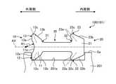
図3は、図1におけるB-B断面に沿った形状を示す図である。図3は、ガスケット100の湾曲部分102の断面構成を示している。図3に示すように、ガスケット100の湾曲部分102は、外周側が外周方向に引っ張られ、内周側が内周方向に収縮するように応力が加わって変形した状態となっている。なお、図3では、湾曲部分102の構成をわかりやすく示すため、実際よりも変形量を大きく示している。 FIG. 3 is a diagram showing a shape along a BB cross section in FIG. 1. FIG. 3 shows the cross-sectional configuration of the
外周側に配置される外周側シール部10には、外周方向に引っ張られる応力が加えられる。この応力により、外周側基部11の外周部は上下に伸びるように変形しようとする。本実施形態において、外周側基部11の外周部には第1凹部11aが設けられる。そのため、外周側基部11は、第1凹部11aが上下方向に開くように変形する。この外周側基部11の変形により、外周側基部11の外周部に無理な力が掛かることなく、第1リップ部12が下方側に向けて突出し、第2リップ部13が上方側に向けて突出する。 A stress that is pulled in the outer peripheral direction is applied to the outer peripheral
外周側基部11の変形により、第1リップ部12及び第2リップ部13は、図3における二点鎖線に示すように、直線部分101と比べて内周側に向いてはいるものの、先端部12c、13cがそれぞれ外周側に向けて突出した状態となっている。したがって、直線部分101及び湾曲部分102のそれぞれにおいて、第1リップ部12及び第2リップ部13は、先端部12c、13cが外周側に向けて突出した状態となっている。 Due to the deformation of the outer peripheral
一方、内周側に配置される内周側シール部20には、内周方向に収縮する応力が加えられる。この応力により、内周側基部21の外周部についても上下に伸びるように変形しようとする。この内周側基部21の変形により、内周側基部21の外周部に無理な力が掛かることなく、第3リップ部22が下方側に向けて突出し、第4リップ部23が上方側に向けて突出する。On the other hand, a stress that contracts in the inner peripheral direction is applied to the inner peripheral
内周側基部21の変形により、第3リップ部22及び第4リップ部23は、図3における二点鎖線に示すように、直線部分101と比べて内周側に向いてはいるものの、先端部22c、23cがそれぞれ外周側に向けて突出した状態となっている。したがって、直線部分101及び湾曲部分102のそれぞれにおいて、第3リップ部22及び第4リップ部23は、先端部22c、23cが外周側に向けて突出した状態となっている。 Due to the deformation of the inner
ガスケット100をケース本体201上に載置した状態で、カバー202を装着することにより、ガスケット100がケース本体201とカバー202との間に挟まれる。例えば、直線部分101及び湾曲部分102のそれぞれにおいて、第1リップ部12及び第2リップ部13は、先端部12c、13cが外周側に向けて突出している。つまり、第1リップ部12及び第2リップ部13は、先端部12c、13cが周方向の全体に亘って、同一側である外周側に向けて突出している。また、第1リップ部12は、先端部12cが内周面12b側の位置でケース本体201に当接している。 By mounting the
この状態からカバー202を装着する場合、カバー202が第2リップ部13の先端部13cのうち内周面13b側の位置に当接し、第2リップ部13を下方に押圧する。図4は、ガスケット100の湾曲部分102において、ケース本体201とカバー202との間に挟まれた状態を示す断面図である。図4に示すように、ガスケット100は、第1リップ部12の先端部12cのうち内周面12b側の位置がケース本体201によって押圧され、第2リップ部13の先端部13cのうち内周面13b側の位置がカバー202によって押圧された状態で挟まれる。これにより、第1リップ部12及び第2リップ部13は、同一側である外周側に弾性変形する。第1リップ部12及び第2リップ部13が周方向の全体に亘って外周側に弾性変形した状態になることで、外周側シール部10において安定したシール性が確保される。 When the
また、内周側シール部20においても同様に、ガスケット100は、第3リップ部22の先端部22cのうち内周面22b側の位置がケース本体201によって押圧され、第4リップ部23の先端部23cのうち内周面23b側の位置がカバー202によって押圧された状態で挟まれる。これにより、第3リップ部22及び第4リップ部23は、同一側である外周側に弾性変形する。第3リップ部22及び第4リップ部23が周方向の全体に亘って外周側に弾性変形した状態になることで、内周側シール部20において十分な変形が確保され、かつ安定したシール性が確保される。 Similarly, in the inner peripheral
このように、本実施形態に係るガスケット100は、ケース本体201と当該ケース本体201に装着されるカバー202との間に配置され、ケース本体201とカバー202との隙間をシールする環状のガスケット100であって、環状であり外周部に一周に亘って第1凹部11aが設けられた外周側基部11と、外周側基部11からケース本体201側かつ外周側に突出する環状の第1リップ部12と、外周側基部11からカバー202側かつ外周側に突出する環状の第2リップ部13と、を有する外周側シール部10と、環状であり外周側シール部10の内周側に配置された内周側基部21と、内周側基部21からケース本体201側かつ外周側に突出する環状の第3リップ部22と、内周側基部21からカバー202側かつ外周側に突出する環状の第4リップ部23と、を有する内周側シール部20と、外周側シール部10と内周側シール部20との間に配置され、外周側基部11と内周側基部21とを連結する連結部30とを備える。As described above, the
この構成により、外周側シール部10と内周側シール部20とが連結部30によって連結された状態で並んで配置されるため、ガスケット100が外周側又は内周側に倒れることを抑制できる。このため、ガスケット100が安定して配置される。また、ガスケット100は、第1リップ部12、第2リップ部13、第3リップ部22及び第4リップ部23が設けられることにより、湾曲部分102において外周側シール部10及び内周側シール部20が弾性変形しにくくなることを抑制できる。このため、ガスケット100は、ケース本体201とカバー202とで挟まれる場合、直線部分101及び湾曲部分102のいずれの部分においても、外周側シール部10及び内周側シール部20が同程度に弾性変形することになる。これにより、ガスケット100の周方向の全体に亘って均一なシールを確保することができる。 With this configuration, since the outer peripheral
また、本実施形態に係るガスケット100において、第1リップ部12は、外周側基部11の外周部に接続される外周面12aと、外周側基部11の内周部に接続され突出方向の先端側に向けて外周面12a側に傾いた形状の内周面12bとを有し、第2リップ部13は、外周側基部11の外周部に接続される外周面13aと、外周側基部11の内周部に接続され突出方向の先端側に向けて外周面13a側に傾いた形状の内周面13bとを有し、第3リップ部22は、内周側基部21の外周部に接続される外周面22aと、内周側基部21の内周部に接続され突出方向の先端側に向けて外周面22a側に傾いた形状の内周面22bとを有し、第4リップ部23は、内周側基部21の外周部に接続される外周面23aと、内周側基部21の内周部に接続され突出方向の先端側に向けて外周面23a側に傾いた形状の内周面23bとを有する。このため、第1リップ部12、第2リップ部13、第3リップ部22及び第4リップ部23は、先端に向けて先細りの形状となる。また、第1リップ部12は、外周側基部11からケース本体201側かつ外周側に突出した形状となり、第2リップ部13は、外周側基部11からカバー202側かつ外周側に突出した形状となる。これにより、ガスケット100がケース本体201とカバー202とで挟まれる場合、第1リップ部12及び第2リップ部13は、同一側である外周側に弾性変形しやすくなる。同様に、第3リップ部22は、内周側基部21からケース本体201側かつ外周側に突出した形状となり、第4リップ部23は、内周側基部21からカバー202側かつ外周側に突出した形状となるため、ガスケット100がケース本体201とカバー202とで挟まれる場合、第3リップ部22及び第4リップ部23は、同一側である外周側に弾性変形しやすくなる。このように、第1リップ部12、第2リップ部13、第3リップ部22及び第4リップ部23が周方向の全体に亘って外周側に弾性変形した状態になることで、外周側シール部10において安定したシール性を確保することができる。 Further, in the
また、本実施形態に係るガスケット100において、第1凹部11aは、円筒面状である。Further, in the
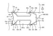
本発明の技術範囲は上記実施形態に限定されるものではなく、本発明の趣旨を逸脱しない範囲で適宜変更を加えることができる。例えば、上記実施形態では、内周側基部21が中実状に設けられた構成を例に挙げて説明したが、これに限定されない。図5は、本実施形態に係るガスケットの他の例を示す断面図である。図5に示すガスケット100Aにおいて、内周側基部21Aは、内部に一周に亘って中空部24を有する。この構成により、内周側シール部20Aでは、内周側基部21Aの内周部に対する応力が中空部24によって吸収される。このため、当該応力が連結部30から外周側シール部10側に伝達されることが抑制され、当該応力による外周側シール部10の変形が抑制される。 The technical scope of the present invention is not limited to the above-described embodiment, and changes can be made as appropriate without departing from the spirit of the present invention. For example, in the above embodiment, the configuration in which the inner peripheral
また、上記した実施形態では、ガスケット100が位置決め部201aに収容された状態で載置される構成を例に挙げて説明したが、これに限定されない。例えば、ガスケット100が、ボルト等の固定部材によりケース本体201及びカバー202の一方に固定される構成であってもよい。この場合、ガスケット100には、固定部材を貫通させるための貫通孔が設けられる。この貫通孔は、例えば連結部30に設けることができる。なお、貫通孔は、外周側シール部10及び内周側シール部20の一部に掛かるように設けられてもよい。また、貫通孔には、固定部材を通過させる金属環が取り付けられてもよい。貫通孔は、例えばガスケット100を製造する際、直線状のゴム部材を形成した後、当該ゴム部材に対して加工することで形成することができる。なお、貫通孔は、ゴム部材の端部同士を接合した後に加工して形成してもよい。 Further, in the above-described embodiment, the configuration in which the
10 外周側シール部
11 外周側基部
11a 第1凹部
12 第1リップ部
12a,13a,22a,23a 外周面
12b,13b,22b,23b 内周面
12c,13c,22c,23c 先端部
13 第2リップ部
20,20A 内周側シール部
21,21A 内周側基部
22 第3リップ部
23 第4リップ部
24 中空部
30 連結部
31 外周側連結部
32 内周側連結部
100,100A ガスケット
101 直線部分
102 湾曲部分
200 ケース
201 ケース本体
201a 位置決め部
202 カバー
AX 中心位置
Sa 第1面
Sb 第2面10 Outer peripheral
2 2
Claims (3)
Translated fromJapanese環状であり外周部に一周に亘って第1凹部が設けられた外周側基部と、前記外周側基部から前記第1部材側かつ外周側に突出する環状の第1リップ部と、前記外周側基部から前記第2部材側かつ外周側に突出する環状の第2リップ部と、を有する外周側シール部と、
環状であり前記外周側シール部の内周側に配置された内周側基部と、前記内周側基部から前記第1部材側かつ外周側に突出する環状の第3リップ部と、前記内周側基部から前記第2部材側かつ外周側に突出する環状の第4リップ部と、を有する内周側シール部と、
板状に形成され、前記外周側シール部と前記内周側シール部との間に配置され、前記外周側基部と前記内周側基部とを連結する連結部と
を備えるガスケット。It is an annular gasketformed by using a rubber material , arranged between the first member and the second member mounted on the first member, and sealing the gap between the first member and the second member. hand,
An outer peripheral side base portion that is annular and has a first concave portion extending around the outer peripheral portion, an annular first lip portion that protrudes from the outer peripheral side base portion to the first member side and the outer peripheral side, and the outer peripheral side base portion. The outer peripheral side sealing portion having the annular second lip portion protruding from the second member side and the outer peripheral side, and the outer peripheral side sealing portion.
An annular third lip portion that is annular and is arranged onthe inner peripheral side of the outer peripheral side seal portion, and an annular third lip portion that protrudes from the inner peripheral side base portion to the first member side and the outer peripheral side, and the inner portion. An inner peripheral side sealing portion having an annular fourth lip portion protruding from the peripheral side base portion to the second member side and the outer peripheral side, and an inner peripheral side sealing portion.
A gasketformed in a plate shape, arranged between the outer peripheral side seal portion and the inner peripheral side seal portion, and provided with a connecting portion for connecting the outer peripheral side base portion and the inner peripheral side base portion.
前記第2リップ部は、前記外周側基部の外周部に接続される第2外周面と、前記外周側基部の内周部に接続され突出方向の先端側に向けて前記第2外周面側に傾いた形状の第2内周面とを有し、
前記第3リップ部は、前記内周側基部の外周部に接続される第3外周面と、前記内周側基部の内周部に接続され突出方向の先端側に向けて前記第3外周面側に傾いた形状の第3内周面とを有し、
前記第4リップ部は、前記内周側基部の外周部に接続される第4外周面と、前記内周側基部の内周部に接続され突出方向の先端側に向けて前記第4外周面側に傾いた形状の第4内周面とを有する
請求項1に記載のガスケット。The first lip portion is connected to the first outer peripheral surface connected to the outer peripheral portion of the outer peripheral side base portion and the first outer peripheral surface side connected to the inner peripheral portion of the outer peripheral side base portion and toward the tip end side in the protruding direction. It has a first inner peripheral surface with an inclined shape, and has an inclined shape.
The second lip portion is connected to a second outer peripheral surface connected to the outer peripheral portion of the outer peripheral side base portion and is connected to the inner peripheral portion of the outer peripheral side base portion to the second outer peripheral surface side toward the tip end side in the protruding direction. It has a second inner peripheral surface with an inclined shape, and has a second inner peripheral surface.
The third lip portion is connected to a third outer peripheral surface connected to the outer peripheral portion of the inner peripheral side base portion and the third outer peripheral surface connected to the inner peripheral portion of the inner peripheral side base portion and directed toward the tip end side in the protruding direction. It has a third inner peripheral surface that is inclined to the side, and has a third inner peripheral surface.
The fourth lip portion is connected to a fourth outer peripheral surface connected to the outer peripheral portion of the inner peripheral side base portion and a fourth outer peripheral surface connected to the inner peripheral portion of the inner peripheral side base portion and directed toward the tip end side in the protruding direction. The gasket according to claim 1, which has a fourth inner peripheral surface having a shape inclined to the side.
請求項1又は請求項2に記載のガスケット。The gasket according to claim 1or2 , wherein the inner peripheral side base portion has a hollow portion inside the entire circumference.
Priority Applications (1)
| Application Number | Priority Date | Filing Date | Title |
|---|---|---|---|
| JP2017205497AJP7015672B2 (en) | 2017-10-24 | 2017-10-24 | gasket |
Applications Claiming Priority (1)
| Application Number | Priority Date | Filing Date | Title |
|---|---|---|---|
| JP2017205497AJP7015672B2 (en) | 2017-10-24 | 2017-10-24 | gasket |
Publications (2)
| Publication Number | Publication Date |
|---|---|
| JP2019078325A JP2019078325A (en) | 2019-05-23 |
| JP7015672B2true JP7015672B2 (en) | 2022-02-03 |
Family
ID=66627679
Family Applications (1)
| Application Number | Title | Priority Date | Filing Date |
|---|---|---|---|
| JP2017205497AActiveJP7015672B2 (en) | 2017-10-24 | 2017-10-24 | gasket |
Country Status (1)
| Country | Link |
|---|---|
| JP (1) | JP7015672B2 (en) |
Families Citing this family (1)
| Publication number | Priority date | Publication date | Assignee | Title |
|---|---|---|---|---|
| JP7437950B2 (en)* | 2020-01-22 | 2024-02-26 | 株式会社デンソーテン | electronic control unit |
Citations (2)
| Publication number | Priority date | Publication date | Assignee | Title |
|---|---|---|---|---|
| JP2005090178A (en) | 2003-09-19 | 2005-04-07 | Nishikawa Rubber Co Ltd | Joint gasket |
| JP2017514087A (en) | 2014-04-17 | 2017-06-01 | ビスタデルテク・リミテッド・ライアビリティ・カンパニーVistadeltek, Llc | Super-sealed gasket for joining high purity fluid passages |
Family Cites Families (1)
| Publication number | Priority date | Publication date | Assignee | Title |
|---|---|---|---|---|
| JPS615448Y2 (en)* | 1980-12-12 | 1986-02-19 |
- 2017
- 2017-10-24JPJP2017205497Apatent/JP7015672B2/enactiveActive
Patent Citations (2)
| Publication number | Priority date | Publication date | Assignee | Title |
|---|---|---|---|---|
| JP2005090178A (en) | 2003-09-19 | 2005-04-07 | Nishikawa Rubber Co Ltd | Joint gasket |
| JP2017514087A (en) | 2014-04-17 | 2017-06-01 | ビスタデルテク・リミテッド・ライアビリティ・カンパニーVistadeltek, Llc | Super-sealed gasket for joining high purity fluid passages |
Also Published As
| Publication number | Publication date |
|---|---|
| JP2019078325A (en) | 2019-05-23 |
Similar Documents
| Publication | Publication Date | Title |
|---|---|---|
| WO2016006393A1 (en) | Gasket | |
| JP5786974B2 (en) | Battery case | |
| JP7715748B2 (en) | Gaskets and sealing structures | |
| KR101947589B1 (en) | Gasket | |
| WO2014054300A1 (en) | Sealing structure | |
| JP2019075235A (en) | Grommet | |
| JP7015672B2 (en) | gasket | |
| JP6948911B2 (en) | gasket | |
| JP6513894B1 (en) | gasket | |
| WO2015159595A1 (en) | Battery pack | |
| JP6372160B2 (en) | Gasket and gasket mounting structure | |
| JP6896924B2 (en) | accumulator | |
| WO2020044910A1 (en) | Gasket | |
| KR101384681B1 (en) | Cover gasket having carrier with improved assemblability | |
| JP2012122518A (en) | Gasket | |
| JP2017182998A (en) | Battery pack | |
| JP2015056568A (en) | Housing and developing housing | |
| CN106151519B (en) | Sealing structure | |
| JP2015155711A (en) | Gas utilization system | |
| CN221897109U (en) | Seals, sealing structures and industrial equipment | |
| JP6885785B2 (en) | Gasket and engine | |
| JP5916960B1 (en) | Terminal box | |
| JP6122176B1 (en) | Waterproof case device | |
| WO2016173543A1 (en) | Elastic sealing element and sealing assembly | |
| JP2011007248A (en) | Gasket |
Legal Events
| Date | Code | Title | Description |
|---|---|---|---|
| RD01 | Notification of change of attorney | Free format text:JAPANESE INTERMEDIATE CODE: A7426 Effective date:20171109 | |
| A521 | Request for written amendment filed | Free format text:JAPANESE INTERMEDIATE CODE: A821 Effective date:20171110 | |
| A621 | Written request for application examination | Free format text:JAPANESE INTERMEDIATE CODE: A621 Effective date:20201015 | |
| A977 | Report on retrieval | Free format text:JAPANESE INTERMEDIATE CODE: A971007 Effective date:20210625 | |
| A131 | Notification of reasons for refusal | Free format text:JAPANESE INTERMEDIATE CODE: A131 Effective date:20210629 | |
| A521 | Request for written amendment filed | Free format text:JAPANESE INTERMEDIATE CODE: A523 Effective date:20210818 | |
| TRDD | Decision of grant or rejection written | ||
| A01 | Written decision to grant a patent or to grant a registration (utility model) | Free format text:JAPANESE INTERMEDIATE CODE: A01 Effective date:20220111 | |
| A61 | First payment of annual fees (during grant procedure) | Free format text:JAPANESE INTERMEDIATE CODE: A61 Effective date:20220124 | |
| R150 | Certificate of patent or registration of utility model | Ref document number:7015672 Country of ref document:JP Free format text:JAPANESE INTERMEDIATE CODE: R150 | |
| R250 | Receipt of annual fees | Free format text:JAPANESE INTERMEDIATE CODE: R250 |