JP7014531B2 - Printing equipment - Google Patents
Printing equipmentDownload PDFInfo
- Publication number
- JP7014531B2 JP7014531B2JP2017121112AJP2017121112AJP7014531B2JP 7014531 B2JP7014531 B2JP 7014531B2JP 2017121112 AJP2017121112 AJP 2017121112AJP 2017121112 AJP2017121112 AJP 2017121112AJP 7014531 B2JP7014531 B2JP 7014531B2
- Authority
- JP
- Japan
- Prior art keywords
- recording paper
- cassette
- printer
- printing apparatus
- base plate
- Prior art date
- Legal status (The legal status is an assumption and is not a legal conclusion. Google has not performed a legal analysis and makes no representation as to the accuracy of the status listed.)
- Active
Links
Images


Classifications
- B—PERFORMING OPERATIONS; TRANSPORTING
- B41—PRINTING; LINING MACHINES; TYPEWRITERS; STAMPS
- B41J—TYPEWRITERS; SELECTIVE PRINTING MECHANISMS, i.e. MECHANISMS PRINTING OTHERWISE THAN FROM A FORME; CORRECTION OF TYPOGRAPHICAL ERRORS
- B41J29/00—Details of, or accessories for, typewriters or selective printing mechanisms not otherwise provided for
- B41J29/02—Framework
- B—PERFORMING OPERATIONS; TRANSPORTING
- B41—PRINTING; LINING MACHINES; TYPEWRITERS; STAMPS
- B41J—TYPEWRITERS; SELECTIVE PRINTING MECHANISMS, i.e. MECHANISMS PRINTING OTHERWISE THAN FROM A FORME; CORRECTION OF TYPOGRAPHICAL ERRORS
- B41J2/00—Typewriters or selective printing mechanisms characterised by the printing or marking process for which they are designed
- B41J2/315—Typewriters or selective printing mechanisms characterised by the printing or marking process for which they are designed characterised by selective application of heat to a heat sensitive printing or impression-transfer material
- B41J2/32—Typewriters or selective printing mechanisms characterised by the printing or marking process for which they are designed characterised by selective application of heat to a heat sensitive printing or impression-transfer material using thermal heads
- B—PERFORMING OPERATIONS; TRANSPORTING
- B41—PRINTING; LINING MACHINES; TYPEWRITERS; STAMPS
- B41J—TYPEWRITERS; SELECTIVE PRINTING MECHANISMS, i.e. MECHANISMS PRINTING OTHERWISE THAN FROM A FORME; CORRECTION OF TYPOGRAPHICAL ERRORS
- B41J11/00—Devices or arrangements of selective printing mechanisms, e.g. ink-jet printers or thermal printers, for supporting or handling copy material in sheet or web form
- B41J11/007—Conveyor belts or like feeding devices
- B—PERFORMING OPERATIONS; TRANSPORTING
- B41—PRINTING; LINING MACHINES; TYPEWRITERS; STAMPS
- B41J—TYPEWRITERS; SELECTIVE PRINTING MECHANISMS, i.e. MECHANISMS PRINTING OTHERWISE THAN FROM A FORME; CORRECTION OF TYPOGRAPHICAL ERRORS
- B41J15/00—Devices or arrangements of selective printing mechanisms, e.g. ink-jet printers or thermal printers, specially adapted for supporting or handling copy material in continuous form, e.g. webs
- B41J15/04—Supporting, feeding, or guiding devices; Mountings for web rolls or spindles
- B41J15/044—Cassettes or cartridges containing continuous copy material, tape, for setting into printing devices
- B—PERFORMING OPERATIONS; TRANSPORTING
- B41—PRINTING; LINING MACHINES; TYPEWRITERS; STAMPS
- B41J—TYPEWRITERS; SELECTIVE PRINTING MECHANISMS, i.e. MECHANISMS PRINTING OTHERWISE THAN FROM A FORME; CORRECTION OF TYPOGRAPHICAL ERRORS
- B41J29/00—Details of, or accessories for, typewriters or selective printing mechanisms not otherwise provided for
- B41J29/02—Framework
- B41J29/023—Framework with reduced dimensions
- B—PERFORMING OPERATIONS; TRANSPORTING
- B41—PRINTING; LINING MACHINES; TYPEWRITERS; STAMPS
- B41J—TYPEWRITERS; SELECTIVE PRINTING MECHANISMS, i.e. MECHANISMS PRINTING OTHERWISE THAN FROM A FORME; CORRECTION OF TYPOGRAPHICAL ERRORS
- B41J29/00—Details of, or accessories for, typewriters or selective printing mechanisms not otherwise provided for
- B41J29/04—Means for attaching machines to baseboards
- B—PERFORMING OPERATIONS; TRANSPORTING
- B41—PRINTING; LINING MACHINES; TYPEWRITERS; STAMPS
- B41J—TYPEWRITERS; SELECTIVE PRINTING MECHANISMS, i.e. MECHANISMS PRINTING OTHERWISE THAN FROM A FORME; CORRECTION OF TYPOGRAPHICAL ERRORS
- B41J29/00—Details of, or accessories for, typewriters or selective printing mechanisms not otherwise provided for
- B41J29/12—Guards, shields or dust excluders
- B41J29/13—Cases or covers
- B—PERFORMING OPERATIONS; TRANSPORTING
- B41—PRINTING; LINING MACHINES; TYPEWRITERS; STAMPS
- B41J—TYPEWRITERS; SELECTIVE PRINTING MECHANISMS, i.e. MECHANISMS PRINTING OTHERWISE THAN FROM A FORME; CORRECTION OF TYPOGRAPHICAL ERRORS
- B41J3/00—Typewriters or selective printing or marking mechanisms characterised by the purpose for which they are constructed
- B41J3/36—Typewriters or selective printing or marking mechanisms characterised by the purpose for which they are constructed for portability, i.e. hand-held printers or laptop printers
- B—PERFORMING OPERATIONS; TRANSPORTING
- B41—PRINTING; LINING MACHINES; TYPEWRITERS; STAMPS
- B41J—TYPEWRITERS; SELECTIVE PRINTING MECHANISMS, i.e. MECHANISMS PRINTING OTHERWISE THAN FROM A FORME; CORRECTION OF TYPOGRAPHICAL ERRORS
- B41J3/00—Typewriters or selective printing or marking mechanisms characterised by the purpose for which they are constructed
- B41J3/44—Typewriters or selective printing mechanisms having dual functions or combined with, or coupled to, apparatus performing other functions
- B41J3/445—Printers integrated in other types of apparatus, e.g. printers integrated in cameras
- G—PHYSICS
- G06—COMPUTING OR CALCULATING; COUNTING
- G06F—ELECTRIC DIGITAL DATA PROCESSING
- G06F3/00—Input arrangements for transferring data to be processed into a form capable of being handled by the computer; Output arrangements for transferring data from processing unit to output unit, e.g. interface arrangements
- G06F3/12—Digital output to print unit, e.g. line printer, chain printer
- G06F3/1201—Dedicated interfaces to print systems
- G06F3/1223—Dedicated interfaces to print systems specifically adapted to use a particular technique
- G06F3/1237—Print job management
- G06F3/1253—Configuration of print job parameters, e.g. using UI at the client
- G06F3/1256—User feedback, e.g. print preview, test print, proofing, pre-flight checks
Landscapes
- Engineering & Computer Science (AREA)
- Theoretical Computer Science (AREA)
- Human Computer Interaction (AREA)
- Physics & Mathematics (AREA)
- General Engineering & Computer Science (AREA)
- General Physics & Mathematics (AREA)
- Sheets, Magazines, And Separation Thereof (AREA)
- Printers Characterized By Their Purpose (AREA)
- Handling Of Cut Paper (AREA)
- Accessory Devices And Overall Control Thereof (AREA)
- Telephone Set Structure (AREA)
Description
Translated fromJapanese本発明は、印刷装置に関する。 The present invention relates to a printing apparatus.
従来より、携帯型のプリンタが存在しているが、このようなプリンタは箱形に形成されており比較的大きく、バッグ等に入れられて持ち運ばれていた。また、プリンタには記録紙や記録紙を入れるホルダ等も必要であり、これらも一緒に持ち運ぶ場合が多い。 Conventionally, portable printers have existed, but such printers are formed in a box shape and are relatively large, and have been carried in a bag or the like. In addition, the printer also requires a recording paper, a holder for storing the recording paper, and the like, and these are often carried together.
近年は、スマートフォン等の携帯情報端末が普及しており、携帯情報端末を用いて、他の情報端末と同様に記録紙に印刷したいといったニーズが考えられる。携帯情報端末は携帯性を有することを特徴としているため、携帯情報端末に接続されるプリンタも小型で携帯性の高いものが好ましい。 In recent years, mobile information terminals such as smartphones have become widespread, and there is a need to use mobile information terminals to print on recording paper in the same manner as other information terminals. Since the mobile information terminal is characterized by having portability, it is preferable that the printer connected to the mobile information terminal is also small and highly portable.
よって、携帯情報端末に接続される、小型で持ち運びやすい印刷装置が求められている。 Therefore, there is a demand for a compact and easy-to-carry printing device connected to a mobile information terminal.
本実施の形態の一観点によれば、記録紙に印刷をするプリンタと、前記プリンタを保持するベース板と、前記ベース板の一方の面に取り付けられ、携帯情報端末を保持するジャケットと、前記ベース板の他方の面に取り付けられ、記録紙を収容するカセットと、を有することを特徴とする。 According to one aspect of the present embodiment, a printer that prints on recording paper, a base plate that holds the printer, a jacket that is attached to one surface of the base plate and holds a portable information terminal, and the like. It is characterized by having a cassette attached to the other side of the base plate and accommodating a recording paper.
開示の印刷装置によれば、小型で持ち運びやすい、携帯情報端末に接続される印刷装置を得ることができる。 According to the disclosed printing apparatus, it is possible to obtain a printing apparatus connected to a portable information terminal, which is small and easy to carry.
本発明を実施するための形態について、以下に説明する。尚、同じ部材等については、同一の符号を付して説明を省略する。本願において、X1-X2方向、Y1-Y2方向、Z1-Z2方向を相互に直交する方向とする。また、X1-X2方向及びY1-Y2方向を含む面をXY面と記載し、Y1-Y2方向及びZ1-Z2方向を含む面をYZ面と記載し、Z1-Z2方向及びX1-X2方向を含む面をZX面と記載する。 The embodiment for carrying out the present invention will be described below. The same members and the like are designated by the same reference numerals and the description thereof will be omitted. In the present application, the X1-X2 direction, the Y1-Y2 direction, and the Z1-Z2 direction are defined as directions orthogonal to each other. Further, the surface including the X1-X2 direction and the Y1-Y2 direction is described as an XY surface, the surface including the Y1-Y2 direction and the Z1-Z2 direction is described as a YZ surface, and the Z1-Z2 direction and the X1-X2 direction are described. The surface including the surface is referred to as a ZX surface.
(印刷装置)
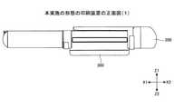
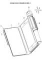
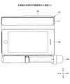
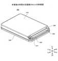
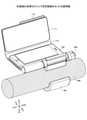
本実施の形態における印刷装置について、図1~図12に基づき説明する。図1は、本実施の形態における印刷装置の斜視図であり、図2は上面図であり、図3は正面図であり、図4は背面図である。図5は、ジャケット110の上蓋111を開いた状態の斜視図であり、図6は上面図であり、図7は底面図であり、図8は正面図であり、図9は背面図であり、図10は側面図である。図11は、印刷装置を上面から見た分解斜視図であり、図12は底面から見た分解斜視図である。(Printing equipment)
The printing apparatus according to this embodiment will be described with reference to FIGS. 1 to 12. 1 is a perspective view of the printing apparatus according to the present embodiment, FIG. 2 is a top view, FIG. 3 is a front view, and FIG. 4 is a rear view. 5 is a perspective view of the
本実施の形態におけるプリンタは、スマートフォン等の携帯情報端末100から受信した情報を記録紙に印刷するものである。印刷装置は、スマホジャケット(以下「ジャケット」)110、ペン型のプリンタ200、記録紙を収容するカセット300、ベース板400を有している。また、スマートフォン等の携帯情報端末100を用いて他から受信した情報を、プリンタを用いて印刷してもよい。 The printer in the present embodiment prints information received from a
(ジャケット)
ジャケット110は合成皮革等により形成されている。携帯情報端末100は、X1-X2方向の長さがY1-Y2方向の長さよりも長い略長方形であって、やや厚い平板状の形状のものであり、ジャケット110はこれに対応した形状の上蓋111と下蓋112とを有している。上蓋111と下蓋112とは、Y1側端部においてX1-X2方向に沿って形成された折り曲げ部113により接続されている。(Jacket)
The
携帯情報端末100にジャケット110が取り付けられた状態では、携帯情報端末100は、ジャケット110の上蓋111と下蓋112との間に挟まれる。具体的には、下蓋112の内側面112aの上に携帯情報端末100の裏面100bを設置し、折り曲げ部113において上蓋111を折り曲げることにより、携帯情報端末100の表面100aが上蓋111により覆われる。携帯情報端末100の表面100aは上蓋111により覆われ、裏面100bは下蓋112により覆われる。 When the
ジャケット110には、上蓋111の折り曲げ部113と接続されている側とは反対側に、磁石を内蔵したマグネット114が設けられている。プリンタ200を保持するクリップ411、412の磁性体材料を含んでいる部分がマグネット114に磁力により引き付けられるため、マグネットを用いることで上蓋111により携帯情報端末100を覆った状態を維持することができる。 The
(プリンタ)
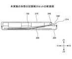
次に、プリンタ200について、図13及び図14に基づき説明する。図13は、プリンタ200の斜視図であり、図14はプリンタ部分の断面図である。プリンタ200は外観が円柱状に形成されており、プリンタ機能と無線による通信機能とを有しているIoT(Internet of Things)デバイスである。(Printer)
Next, the
プリンタ200は、サーマルヘッド等の印刷ヘッド211、プラテンローラ212、給紙ローラ213、記録紙ガイド214、加圧バネ、制御基板216、内蓋250、外蓋260を有している。印刷ヘッド211は加圧バネのバネ力によりプラテンローラ212に押されている。記録紙は、微粘着性の給紙ローラ213が設けられている側から、記録紙ガイド214に沿ってプリンタ200に入り、印刷ヘッド211とプラテンローラ212との間で挟まれた状態で、プラテンローラ212により搬送されながら印刷されて排紙される。制御基板216には、プリンタ200の制御を行う電子回路や電子部品が搭載されている。 The
内蓋250及び外蓋260は円筒状であり、外蓋260の内側に内蓋250が入るように形成されている。内蓋250には、その母線に沿って開口している給紙口251及び排紙口252が設けられており、外蓋260にはその母線に沿って開口している給紙口261及び排紙口262が設けられている。外蓋260は、その内側に内蓋250が入れられた状態で内蓋250に対し回転可能である。プリンタ200により印刷を行う際には、内蓋250の給紙口251と外蓋260の給紙口261の位置が一致して開いており、内蓋250の排紙口252と外蓋260の排紙口262の位置が一致して開いている。このように開いている給紙口251及び給紙口261より記録紙がプリンタ200に入り、排紙口252及び排紙口262より排紙される。 The
プリンタ200においては、印刷が可能な給紙口251、261が開放している状態で、記録紙が収納されたカセット300を給紙口261に接続できる。プリンタ200で印刷を行う際には、印刷データが携帯情報端末100よりプリンタ200にBLE(Bluetooth Low Energy)等の無線通信により送信される。プリンタ200はアンテナから印刷データを受信し、記録紙に印刷が行われる。 In the
プリンタ200の筐体内部には、充電池であるリチウムイオン電池が入れられた電源280が設けられている。リチウムイオン電池より供給された電力により、プリンタ200を駆動することができる。 Inside the housing of the
プリンタ200は、直径が約18mm、長さは約165mmと小型であり、ストレスを伴うことなく持ち運びができる。プリンタ200にはフック290が設けられており、ペンと同様に衣服の胸のポケット等にさした状態で持ち運ぶことが可能である。 The
(ベース板)
次に、ベース板400について、図15及び図16に基づき説明する。図15はベース板400を上面から見た斜視図であり、図16は底面から見た斜視図である。(Base plate)
Next, the
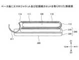
ベース板400は樹脂材料等により形成されており、XY面に略平行な板状であって、携帯情報端末100やジャケット110の下蓋112の形状に対応して、X1-X2方向の幅がY1-Y2方向の幅よりも長い略長方形の平板状に形成されている。ベース板400のY2側のX1-X2方向に沿った側部には、プリンタ200を取り付けるためのクリップ411、412が設けられている。クリップ411、412は、プリンタ200が入れられるように円環の一部を取り除いた形状に形成されている。プリンタ200がクリップ411、412に取り付けられ保持されている状態では、プリンタ200の長手方向はX1-X2方向となり、記録紙150はY2方向に排出される。 The
また、図11及び図12に示されるように、ベース板400のZ1側の面400aには、ジャケット110の下蓋112が取り付けられ、ベース板400のZ2側の面400bにはカセット300が取り付けられる。また、Z2側の面400bのX2側の端部近傍には、バランスをとるための錘420が設けられている。 Further, as shown in FIGS. 11 and 12, the
(カセット)
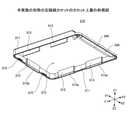
次に、カセット300について、図17から図21に基づき説明する。図17は、カセット300を上面から見た斜視図であり、図18は側面図であり、図19は分解斜視図であり、図20は上蓋を底面から見た斜視図であり、図21は断面図である。尚、本実施の形態における記録紙は、ラベル用紙等であってもよい。(cassette)
Next, the
カセット300は、上蓋310、下蓋320、第1の搬送ローラ330、第2の搬送ローラ340を有している。カセット300は、Y1-Y2方向の長さがX1-X2方向よりも長い略長方形に形成されている。よって、上蓋310及び下蓋320もY1-Y2方向の長さがX1-X2方向よりも長い。 The
上蓋310の周囲には、Z2側に延びる側壁311が設けられている。側壁311の内側は、Z1側が凹んだ凹部312となる。また、側壁311の内側には、Z2方向に延びる記録紙ガイド313が5個設けられている。具体的には、X1側のY1-Y2方向に沿った側壁311の内側には、Y1-Y2方向に沿って2つの記録紙ガイド313が設けられており、X2側のY1-Y2方向に沿った側壁311の内側には、Y1-Y2方向に沿って2つの記録紙ガイド313が設けられている。Y1-Y2方向に沿って、X1側とX2側に設けられた記録紙ガイド313は対向している。また、Y1側のX1-X2方向に沿った側壁311の内側には記録紙ガイド313が1つ設けられている。 A
各々の記録紙ガイド313のZ2側の先端には、外側に広がる傾斜部313aが形成されている。後述するように、印刷装置により記録紙150に印刷することにより、積み重ねられた記録紙150は減少し、印刷装置は下方向、即ち、Z2方向に下がるが、傾斜部313aを設けることにより、印刷装置がX1-X2方向やY1-Y2方向にずれてバランスを崩し、積み重ねられた記録紙150が倒れることを防いでいる。即ち、傾斜部313aを設けることにより、上蓋310の側壁311の内側は、なだらかな末広がりとなり、記録紙150が上蓋310の凹部312に入り込みやすくなっている。具体的には、記録紙150の側面となるX1-X2方向、及び、Y1-Y2方向が揃っておらず、凸凹していても、記録紙150に印刷がなされ下に降下した際に、傾斜部313aにより記録紙150が、上蓋310の凹部312に入り込み、これにより、印刷装置がX1-X2方向やY1-Y2方向にずれてバランスを崩し、積み重ねられた記録紙150が倒れることを防いでいる。 An
上蓋310のY2側には、第1の搬送ローラ330及び第2の搬送ローラ340が、X1-X2方向が長手方向となるように設けられている。更に、この近傍には、記録紙をプリンタに供給するための開口314が形成されている。また、側壁311のY1側の内側には、記録紙ガイド313の両側に2つのロック溝315が設けられている。 On the Y2 side of the
下蓋320の周囲には、Z1側に延びる側壁321が設けられている。側壁321の内側はZ2側が凹んだ凹部322となる。また、側壁321の内側には、Z1側に延びる記録紙ガイド323が2個設けられている。具体的には、X1側のY1-Y2方向に沿った側壁321の内側、及び、X2側のY1-Y2方向に沿った側壁321の内側に、各々記録紙ガイド323が設けられている。2つの記録紙ガイド323は対向している。また、Y1側のX1-X2方向に沿った側壁321の内側には、X1-X2方向に沿って2つの記録紙ガイド324が設けられており、各々の記録紙ガイド324のZ1側の先端の近傍には、ロック爪324aが設けられている。また、Y2側のX1-X2方向に沿った側壁321の内側には、X1-X2方向に沿ったロック爪325が設けられている。 A
上蓋310と下蓋320とは、凹部312と凹部322とが対向した状態で接続される。この状態で、下蓋320の記録紙ガイド324の先端に設けられたロック爪324aが、上蓋310の側壁311の内側に設けられているロック溝315に入り込み、また、下蓋320のロック爪325が上蓋310の開口314の縁に引っ掛かり、上蓋310と下蓋320との接続状態が維持される。凹部312と凹部322との間に形成される空間内に記録紙を設置することができる。 The
凹部322の底面322aには板バネ350が設けられている。板バネ350は、図21に示すように、上蓋310と下蓋320との間に収納されている記録紙150の枚数が少なくなった場合に、バネ力により記録紙150をZ1方向に持ちあげ、記録紙150を第2の搬送ローラ340に接触させる機能を有している。これにより、カセット300に収納されている記録紙150の枚数が少なくなっても、円滑に記録紙150を供給することができる。 A
本実施の形態においては、上蓋310と下蓋320とが接続されている状態でカセット300を用いてもよいが、上蓋310と下蓋320とを分離し、上蓋310と下蓋320との間に記録紙を設置してもよい。図22から図24に示すように、凹部312と凹部322とを対向させた状態で、上蓋310と下蓋320の間に積み重ねられた記録紙150を設置してもよい。尚、図22は、この状態を示す斜視図であり、図23は側面図であり、図24は正面図である。 In the present embodiment, the
上蓋310と下蓋320とが接続されている状態では、記録紙150は上蓋310と下蓋320との間の空間内に設置されるため、あまり多くの枚数を収納することができない。これに対し、上蓋310と下蓋320とを分離した状態では、上蓋310と下蓋320との間に多くの枚数の記録紙150を設置することができ、記録紙150が多い場合に対応できる。尚、本実施の形態において用いられる記録紙150の大きさは、例えば、A8(52mm×74mm)である。 When the
本実施の形態では、記録紙として単票を用いている。ロール紙を用いた場合には、印刷装置を小型にすることに伴い半径の小さなロール紙を用いることが必要となるが、半径の小さなロール紙を用いると、印刷後に強いカールが残ってしまい取り扱いにくい。このことは、印刷装置が小さくなればなるほど強くなる。よって、本実施の形態では、小型になってもカール等が残ることのない単票を記録紙として用いている。但し、本実施の形態による印刷装置でロール紙を用いることも当然可能である。 In this embodiment, a single sheet is used as the recording paper. When roll paper is used, it is necessary to use roll paper with a small radius due to the miniaturization of the printing device. However, if roll paper with a small radius is used, strong curls remain after printing and it is handled. Hateful. This becomes stronger as the printing device becomes smaller. Therefore, in the present embodiment, a single sheet that does not leave curls or the like even when the size is reduced is used as the recording paper. However, it is of course possible to use roll paper in the printing apparatus according to the present embodiment.
(ジャケットとカセットとの接続)
次に、互いに接続された状態のジャケット110とカセット300について、図25から図28に基づき説明する。尚、図25は互いに接続されたジャケット110とカセット300とを底面から見た斜視図であり、図26は上面から見た斜視図であり、図27は側面図であり、図28は正面図である。尚、図25から図28に示されているカセット300は、携帯する際に開口314よりゴミ等が入るのを防ぐため、開口314が開口蓋により閉じられている状態のものを示している。(Connection between jacket and cassette)
Next, the
本実施の形態においては、上述したように、ベース板400のZ1側の面400aには、ジャケット110の下蓋112の外側面112bが取り付けられ、ベース板400のZ2側の面400bには、上蓋310の外側の面が取り付けられる。 In the present embodiment, as described above, the
印刷装置は、ベース板400、ジャケット110、カセット300の各々が分離されるものであってもよい。また、ベース板400とジャケット110が一体化されたものであってもよく、ベース板400とカセット300が一体化されたものであってもよい。更には、ベース板400、ジャケット110、カセット300が一体化されたものであってもよい。 The printing apparatus may be one in which each of the
また、ベース板400の面400bの、カセット300が取り付けられていないX1側には、プリンタ200を駆動するための不図示のバッテリを設置してもよい。この場合、プリンタ200から電源280を取り外し、ベース板400に取り付けられたバッテリと接続してもよい。 Further, a battery (not shown) for driving the
本実施の形態における印刷装置は、図25から図28に示す状態のクリップ411、412にプリンタ200を入れることにより、図1から図10に示す印刷装置となる。この際、カセット300の開口314にプリンタ200の一部が入り込み、開口314と給紙口251及び排紙口252とがつながった状態となる。 The printing device according to the present embodiment becomes the printing device shown in FIGS. 1 to 10 by inserting the
(印刷動作)
次に、印刷装置の印刷について、図29に基づき説明する。図29はプリンタ200とカセット300とが接続されている状態を示す。尚、図29では、便宜上、上蓋310と下蓋320とが接続されている状態を示しており、ジャケット110及びベース板400は省略されている。(Printing operation)
Next, printing of the printing apparatus will be described with reference to FIG. 29. FIG. 29 shows a state in which the
クリップ411、412にプリンタ200を入れ、カセット300の開口314とプリンタ200の給紙口251及び排紙口252とがつながった状態では、プリンタ200の給紙ローラ213とカセット300の第1の搬送ローラ330とが接触した状態となる。第1の搬送ローラ330は給紙ローラ213の回転を受けて回転する。カセット300には、第1の搬送ローラ330の回転に伴い第2の搬送ローラ340を回転させる第1のギア371及び第2のギア372が設けられている。第1の搬送ローラ330には第1のギア371が接続されており、第1のギア371には第2のギア372が接続されており、第2のギア372には第2の搬送ローラ340が接続されている。尚、図29においては、第1のギア371及び第2のギア372の歯は、便宜上省略されている。 When the
プリンタ200で印刷を行う際には、記録紙を印刷ヘッド211に向けて搬送するために、給紙ローラ213が図示反時計回りに回転する。給紙ローラ213が反時計回りに回転すると、給紙ローラ213に接触している第1の搬送ローラ330は時計回りに回転し、この回転が第1のギア371及び第2のギア372を介し第2の搬送ローラ340に伝達される。第1の搬送ローラ330が時計回りに回転すると、第1のギア371が反時計回りに回転し、第2のギア372が時計回りに回転し、第2の搬送ローラ340が反時計回りに回転する。 When printing is performed by the
第2の搬送ローラ340は一番上の記録紙の表面と接触しており、第2の搬送ローラ340が反時計回りに回転することにより、記録紙はY2方向に動き、プリンタ200に向けて搬送され、開口314と給紙口251及び排紙口252とがつながっている領域を通り、給紙ローラ213と第1の搬送ローラ330との間に挟まれて、印刷ヘッド211に向けて搬送される。第1の搬送ローラ330及び第2の搬送ローラ340は、ワンウェイ機能を有している。 The
印刷装置において印刷を行う場合には、ジャケット110の上蓋111を開き、携帯情報端末100に設けられたタッチパネルを操作することにより、印刷の指示を携帯情報端末100に入力する。携帯情報端末100のタッチパネル操作で指示などを入力することにより、携帯情報端末100のメモリに記憶された印刷情報や印刷を指示するための信号が、BLE等の通信により印刷装置に送信され、この情報に基づき記録紙に印刷が行われる。 When printing is performed by the printing device, the printing instruction is input to the
(印刷装置の使用方法)
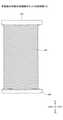
次に、本実施の形態における印刷装置の使用方法について、図30に基づき説明する。本実施の形態では、カセット300の上蓋310と下蓋320とを分離し、上蓋310の凹部312と下蓋320の凹部322とを対向させた状態で、上蓋310と下蓋320との間に積み重ねられた記録紙150を設置する。このように記録紙150を設置することにより、カセット300の大きさに関係なく、多くの枚数、例えば、100~300枚の記録紙150をカセット300に設置することが可能であり、多数の記録紙に印刷を行いたい場合に対応できる。カセット300の上蓋310と下蓋320とを分離することにより、積み重ねられた記録紙150の側面、即ち、X1-X2方向やY1-Y2方向に側壁を有しない仮想のスタックホルダー(VSH:virtual stack holder)が形成される。尚、Z2方向が重力方向である。本実施の形態における印刷装置を持ち運ぶ際には、カセット300の上蓋310と下蓋320とを接続した状態で持ち運ぶ。(How to use the printing device)
Next, a method of using the printing apparatus in the present embodiment will be described with reference to FIG. In the present embodiment, the
本実施の形態においては、図30に示すように、記録紙150を高く積み重ねた状態でも、印刷装置がバランスを崩すことなく図30に示される状態を維持するために、ベース板400のX2側の端部近傍には重心を調節する重心調節部となる錘420が設けられている。錘420は、印刷装置の重心が記録紙150の紙面の中心と一致するように重さや設置位置が調整される。錘420を設けることにより、上蓋310と下蓋320との間に多くの枚数の記録紙150を設置しても、印刷装置がバランスを崩すことはなく、積み重ねられた記録紙150が崩れることはない。錘420は、ベース板400に、プリンタ200、ジャケット110及びカセット300の上蓋310が取り付けられ、ジャケット110に携帯情報端末が保持されている状態のものの重心と、記録紙150の紙面の中心とが一致するように取り付けられている。尚、錘420は、長手方向は、携帯情報端末のヘッド側となるX2方向側が軽くなる為、回転モーメントを相殺するように調整するため、ヘッド側となるX2方向側の底面に設けられている。また、記録紙150の幅方向には、携帯情報端末は均等であるため、ジャケット110とプリンタ200、カセット300の上蓋310による重心設計を行う。 In the present embodiment, as shown in FIG. 30, in order to maintain the state shown in FIG. 30 without losing the balance of the printing apparatus even when the
このように記録紙150の上に印刷装置を設置している状態では、印刷装置の自重が積み重ねられた記録紙150に加わる。このため、一番上の記録紙150は、カセット300の第2の搬送ローラ340と接触している。 In the state where the printing apparatus is installed on the
このため、上述したように、第2の搬送ローラ340が反時計回りに回転すると、一番上の記録紙150はY2方向に搬送され、給紙口251及び排紙口252に向けて搬送される。尚、上から2枚目以降の記録紙150が一番上の記録紙150とともに搬送されることを防ぐため、上蓋310には記録紙係止部が設けられていてもよい。記録紙係止部は、一番上の記録紙150が第2の搬送ローラ340が反時計回りに回転し、Y2方向に搬送された際に、2枚目以降の記録紙150のY2方向側の端部を押さえ、一番目の記録紙150とともに搬送されることを防ぐためのものである。 Therefore, as described above, when the
印刷装置により記録紙150に印刷を行うと、積み重ねられた記録紙150は徐々に減り、図31に示されるような状態となる。更に印刷を行うことにより、図32に示すように上蓋310と下蓋320とが接続される。この状態では、記録紙150は、図21に示されるように下蓋320に設けられた板バネ350により上方向、即ち、Z1方向に押し上げられるため、一番上の記録紙150の表面が第2の搬送ローラ340と接触している状態が維持される。 When printing is performed on the
また、印刷装置は、図33及び図34に示すように、長い記録紙151に印刷をすることも可能である。図33はこの状態の様子を示す斜視図であり、図34は上面図である。 The printing apparatus can also print on the
図33及び図34状態では、記録紙151の長手方向がX1-X2方向となるように設置し、プリンタ200は電源280を外してベース板400のX2側の端に設置する。このため、クリップの位置もベース板400のY2側の側面ではなく、X2側の側面に設けられる。この状態では、プリンタ200は長手方向がY1-Y2方向となるように設置され、記録紙151はX2方向に排出される。 In the states of FIGS. 33 and 34, the
(クリップ型カセット)
本実施の形態におけるカセットは、図35及び図36に示されるように、円筒状に形成されたクリップ型のカセット301であってもよい。クリップ型のカセット301における開口部301aを形成しているクリップ部分は、腕クリップであり、腕等に取り付けることができる。記録紙は、カセット301の内部に設置することができる。このカセット301は、開口部301aに印刷装置を支持するための円柱状の支持体500を入れることにより、図37に示されるように、支持体500に自由に取り付けることができ、印刷等の作業における自由度を高めることができる。(Clip type cassette)
As shown in FIGS. 35 and 36, the cassette in the present embodiment may be a clip-
カセット301の内部には、長さが150mmの長い記録紙(長票)であれば20~30枚程度入れることができる。カセット301の円筒部分の半径は大きいため、記録紙のカール等は殆どない。カセット301の内部には、長票ではなく、長さの短い短票を入れることも可能であり、この場合には、カセット301の内部に100~150枚程度の短票を入れることができる。 About 20 to 30 sheets of long recording paper (long sheet) having a length of 150 mm can be put inside the
このような印刷装置においても、携帯情報端末100からの情報をタッチパネルによる操作に基づき、記録紙に印刷して出力することができる。 Even in such a printing device, the information from the
以上、本発明の実施に係る形態について説明したが、上記内容は、発明の内容を限定するものではない。 Although the embodiment of the present invention has been described above, the above contents do not limit the contents of the invention.
100 携帯情報端末
110 ジャケット
200 プリンタ
212 プラテンローラ
213 給紙ローラ
251、261 給紙口
252、262 排紙口
260 外蓋
300 カセット
310 上蓋
313、323、324 記録紙ガイド
314 開口
315 ロック溝
320 下蓋
324a、325 ロック爪
330 第1の搬送ローラ
340 第2の搬送ローラ
350 板バネ
400 ベース板
411、412 クリップ
420 錘100
Claims (7)
Translated fromJapanese前記プリンタを保持するクリップを備えたベース板と、
前記ベース板の一方の面に取り付けられ、記録紙を収容するカセットと、
を有し、
前記ベース板の他方の面に携帯情報端末を保持するジャケットが取り付けられ、
前記プリンタ及び前記カセットは前記ベース板に着脱可能である
ことを特徴とする印刷装置。A printer that prints on chart paper and
A base plate with a clip to hold the printer and
A cassette attached to one side of the base plate and accommodating recording paper,
Have,
A jacket for holding a personal digital assistant is attached tothe other surface of the base plate.
The printer and the cassette can be attached to and detached from the base plate.
A printing device characterized by that.
前記カセットは、前記給紙ローラに接して回転する第1の搬送ローラと、前記第1の搬送ローラの回転に伴い回転する、前記カセットに収容された記録紙の表面に接触する第2の搬送ローラと、
を有することを特徴とする請求項1から3のいずれか一項に記載の印刷装置。The printer has a paper feed roller that feeds the recording paper.
The cassette has a first transfer roller that rotates in contact with the paper feed roller and a second transfer that contacts the surface of the recording paper housed in the cassette, which rotates with the rotation of the first transfer roller. With Laura,
The printing apparatus according to any one of claims 1 to 3, wherein the printing apparatus is characterized by having.
前記記録紙は、前記上蓋と前記下蓋との間に積み重ねられることを特徴とする請求項1から4のいずれか一項に記載の印刷装置。The cassette has an upper lid and a lower lid separable from the upper lid.
The printing apparatus according to any one of claims 1 to 4, wherein the recording paper is stacked between the upper lid and the lower lid.
Priority Applications (6)
| Application Number | Priority Date | Filing Date | Title |
|---|---|---|---|
| JP2017121112AJP7014531B2 (en) | 2017-06-21 | 2017-06-21 | Printing equipment |
| US15/993,820US10442224B2 (en) | 2017-06-21 | 2018-05-31 | Printing apparatus |
| EP18176486.1AEP3418062B1 (en) | 2017-06-21 | 2018-06-07 | Printing apparatus |
| CN201810597158.XACN109094209B (en) | 2017-06-21 | 2018-06-12 | Printing device |
| CN202110123071.0ACN112959824B (en) | 2017-06-21 | 2018-06-12 | Printing device |
| KR1020180070248AKR20180138538A (en) | 2017-06-21 | 2018-06-19 | Printing device |
Applications Claiming Priority (1)
| Application Number | Priority Date | Filing Date | Title |
|---|---|---|---|
| JP2017121112AJP7014531B2 (en) | 2017-06-21 | 2017-06-21 | Printing equipment |
Publications (2)
| Publication Number | Publication Date |
|---|---|
| JP2019005923A JP2019005923A (en) | 2019-01-17 |
| JP7014531B2true JP7014531B2 (en) | 2022-02-01 |
Family
ID=62563078
Family Applications (1)
| Application Number | Title | Priority Date | Filing Date |
|---|---|---|---|
| JP2017121112AActiveJP7014531B2 (en) | 2017-06-21 | 2017-06-21 | Printing equipment |
Country Status (5)
| Country | Link |
|---|---|
| US (1) | US10442224B2 (en) |
| EP (1) | EP3418062B1 (en) |
| JP (1) | JP7014531B2 (en) |
| KR (1) | KR20180138538A (en) |
| CN (2) | CN109094209B (en) |
Families Citing this family (2)
| Publication number | Priority date | Publication date | Assignee | Title |
|---|---|---|---|---|
| JP7476043B2 (en) | 2020-09-07 | 2024-04-30 | 東芝テック株式会社 | Color changing device |
| JP7499122B2 (en) | 2020-09-07 | 2024-06-13 | 東芝テック株式会社 | Mobile Printer |
Citations (4)
| Publication number | Priority date | Publication date | Assignee | Title |
|---|---|---|---|---|
| JP2002529280A (en) | 1998-11-09 | 2002-09-10 | シルバーブルック リサーチ プロプライエタリイ、リミテッド | Digital camera device with built-in printer |
| JP2003500236A (en) | 1999-05-25 | 2003-01-07 | シルバーブルック リサーチ プロプライエタリー リミテッド | Compact color printer module |
| US20060023251A1 (en) | 2001-12-07 | 2006-02-02 | Zih Corp. | Printer attachable to various models and types of portable devices and terminals for operation therewith |
| JP2014103642A (en) | 2012-11-22 | 2014-06-05 | Dainippon Printing Co Ltd | Mounting fixture for mobile terminal |
Family Cites Families (20)
| Publication number | Priority date | Publication date | Assignee | Title |
|---|---|---|---|---|
| JPH02119436U (en)* | 1989-03-10 | 1990-09-26 | ||
| JPH0452163A (en)* | 1990-06-19 | 1992-02-20 | Matsushita Electric Ind Co Ltd | Printer device |
| JPH07249135A (en)* | 1994-03-08 | 1995-09-26 | Hitachi Ltd | Paper issuing device |
| JP3061571B2 (en)* | 1996-07-16 | 2000-07-10 | アルプス電気株式会社 | Paper cassette |
| JPH11138911A (en) | 1997-11-07 | 1999-05-25 | F & F:Kk | Printing equipment |
| AUPP702098A0 (en)* | 1998-11-09 | 1998-12-03 | Silverbrook Research Pty Ltd | Image creation method and apparatus (ART73) |
| AU2004201738B2 (en) | 1999-05-25 | 2006-04-06 | Zamtec Limited | A stackable printer system |
| JP2001072261A (en)* | 1999-09-03 | 2001-03-21 | Fuji Photo Film Co Ltd | Recording paper package |
| JP2001253137A (en) | 2000-03-10 | 2001-09-18 | Fuji Photo Film Co Ltd | Portable printer |
| JP2003094750A (en) | 2001-09-20 | 2003-04-03 | F & F:Kk | Printer |
| JP2003256075A (en) | 2002-03-01 | 2003-09-10 | Nippon Acty Systems Co Ltd | Case for portable electronic terminal |
| JP2004350022A (en) | 2003-05-22 | 2004-12-09 | Alps Electric Co Ltd | Repeating device for mobile device |
| JP4581531B2 (en)* | 2004-07-27 | 2010-11-17 | ソニー株式会社 | Paper discharge tray, paper supply / discharge device, image forming device, and information display device |
| JP4851366B2 (en)* | 2007-03-02 | 2012-01-11 | 株式会社リコー | Sheet conveying apparatus, image reading apparatus, and image forming apparatus |
| CN102806779A (en)* | 2011-06-01 | 2012-12-05 | 鸿富锦精密工业(深圳)有限公司 | Portable printer |
| CN203510998U (en)* | 2013-09-17 | 2014-04-02 | 杭州仁盈科技有限公司 | Multifunctional portable intelligent service terminal device |
| CN104714597A (en)* | 2013-12-13 | 2015-06-17 | 代明远 | Carrying device of laptop |
| CN106274077A (en)* | 2015-05-29 | 2017-01-04 | 周利英 | Multipurpose printer |
| CN205498372U (en)* | 2016-04-08 | 2016-08-24 | 北京清青蓝图科技有限公司 | Portable removal print system based on believe a little that public serves platform |
| CN206287669U (en)* | 2016-11-30 | 2017-06-30 | 山东东营烟草有限公司 | A kind of portable price tag printer |
- 2017
- 2017-06-21JPJP2017121112Apatent/JP7014531B2/enactiveActive
- 2018
- 2018-05-31USUS15/993,820patent/US10442224B2/enactiveActive
- 2018-06-07EPEP18176486.1Apatent/EP3418062B1/enactiveActive
- 2018-06-12CNCN201810597158.XApatent/CN109094209B/enactiveActive
- 2018-06-12CNCN202110123071.0Apatent/CN112959824B/enactiveActive
- 2018-06-19KRKR1020180070248Apatent/KR20180138538A/ennot_activeCeased
Patent Citations (4)
| Publication number | Priority date | Publication date | Assignee | Title |
|---|---|---|---|---|
| JP2002529280A (en) | 1998-11-09 | 2002-09-10 | シルバーブルック リサーチ プロプライエタリイ、リミテッド | Digital camera device with built-in printer |
| JP2003500236A (en) | 1999-05-25 | 2003-01-07 | シルバーブルック リサーチ プロプライエタリー リミテッド | Compact color printer module |
| US20060023251A1 (en) | 2001-12-07 | 2006-02-02 | Zih Corp. | Printer attachable to various models and types of portable devices and terminals for operation therewith |
| JP2014103642A (en) | 2012-11-22 | 2014-06-05 | Dainippon Printing Co Ltd | Mounting fixture for mobile terminal |
Also Published As
| Publication number | Publication date |
|---|---|
| CN112959824A (en) | 2021-06-15 |
| CN109094209B (en) | 2023-03-24 |
| CN109094209A (en) | 2018-12-28 |
| EP3418062A1 (en) | 2018-12-26 |
| US10442224B2 (en) | 2019-10-15 |
| KR20180138538A (en) | 2018-12-31 |
| EP3418062B1 (en) | 2021-12-15 |
| US20180370262A1 (en) | 2018-12-27 |
| JP2019005923A (en) | 2019-01-17 |
| CN112959824B (en) | 2023-03-28 |
Similar Documents
| Publication | Publication Date | Title |
|---|---|---|
| CN103207646B (en) | Portable terminal with supporting plate | |
| JPH05507803A (en) | portable computer | |
| WO1992000197A1 (en) | Portable printer | |
| JP7014531B2 (en) | Printing equipment | |
| EP3502021B1 (en) | Sheet cassette | |
| US20230115479A1 (en) | Printing device and printing method | |
| JP7244608B2 (en) | Recording paper cassette | |
| JP7322268B2 (en) | Recording paper cassette | |
| JP6901352B2 (en) | Recording paper cassette and printing equipment | |
| JP2002059608A (en) | Printer | |
| JP2001253557A (en) | Printing paper sheet storing cassette | |
| JP2001253556A (en) | Printing paper sheet storing cassette | |
| JP4290843B2 (en) | Printing paper storage cassette | |
| JP3284716B2 (en) | Printing device | |
| JP2001253559A (en) | Printing paper sheet storing cassette | |
| JP2001253564A (en) | Printing sheet storing cassette | |
| JP2001253554A (en) | Printing paper sheet storing cassette | |
| JP2001253560A (en) | Printing paper sheet storing cassette | |
| CN113696635A (en) | Printing device | |
| JP2001253555A (en) | Printing paper sheet storing cassette | |
| JP2001253565A (en) | Printing sheet storing cassette | |
| JP2004123321A (en) | Sheet material feeding device and image forming device | |
| JP2006289898A (en) | Printing device |
Legal Events
| Date | Code | Title | Description |
|---|---|---|---|
| A621 | Written request for application examination | Free format text:JAPANESE INTERMEDIATE CODE: A621 Effective date:20200618 | |
| A977 | Report on retrieval | Free format text:JAPANESE INTERMEDIATE CODE: A971007 Effective date:20210414 | |
| A131 | Notification of reasons for refusal | Free format text:JAPANESE INTERMEDIATE CODE: A131 Effective date:20210420 | |
| A521 | Request for written amendment filed | Free format text:JAPANESE INTERMEDIATE CODE: A523 Effective date:20210618 | |
| A131 | Notification of reasons for refusal | Free format text:JAPANESE INTERMEDIATE CODE: A131 Effective date:20210907 | |
| A521 | Request for written amendment filed | Free format text:JAPANESE INTERMEDIATE CODE: A523 Effective date:20211108 | |
| TRDD | Decision of grant or rejection written | ||
| A01 | Written decision to grant a patent or to grant a registration (utility model) | Free format text:JAPANESE INTERMEDIATE CODE: A01 Effective date:20220104 | |
| A61 | First payment of annual fees (during grant procedure) | Free format text:JAPANESE INTERMEDIATE CODE: A61 Effective date:20220120 | |
| R150 | Certificate of patent or registration of utility model | Ref document number:7014531 Country of ref document:JP Free format text:JAPANESE INTERMEDIATE CODE: R150 | |
| R250 | Receipt of annual fees | Free format text:JAPANESE INTERMEDIATE CODE: R250 |