JP7010026B2 - Printer and printer control method - Google Patents
Printer and printer control methodDownload PDFInfo
- Publication number
- JP7010026B2 JP7010026B2JP2018011333AJP2018011333AJP7010026B2JP 7010026 B2JP7010026 B2JP 7010026B2JP 2018011333 AJP2018011333 AJP 2018011333AJP 2018011333 AJP2018011333 AJP 2018011333AJP 7010026 B2JP7010026 B2JP 7010026B2
- Authority
- JP
- Japan
- Prior art keywords
- printing unit
- state
- information
- unit
- display
- Prior art date
- Legal status (The legal status is an assumption and is not a legal conclusion. Google has not performed a legal analysis and makes no representation as to the accuracy of the status listed.)
- Active
Links
Images


Classifications
- G—PHYSICS
- G06—COMPUTING OR CALCULATING; COUNTING
- G06F—ELECTRIC DIGITAL DATA PROCESSING
- G06F3/00—Input arrangements for transferring data to be processed into a form capable of being handled by the computer; Output arrangements for transferring data from processing unit to output unit, e.g. interface arrangements
- G06F3/12—Digital output to print unit, e.g. line printer, chain printer
- G06F3/1201—Dedicated interfaces to print systems
- G06F3/1223—Dedicated interfaces to print systems specifically adapted to use a particular technique
- G06F3/1229—Printer resources management or printer maintenance, e.g. device status, power levels
- G06F3/1234—Errors handling and recovery, e.g. reprinting
- G06F3/1235—Errors handling and recovery, e.g. reprinting caused by end of consumables, e.g. paper, ink, toner
- H—ELECTRICITY
- H04—ELECTRIC COMMUNICATION TECHNIQUE
- H04N—PICTORIAL COMMUNICATION, e.g. TELEVISION
- H04N1/00—Scanning, transmission or reproduction of documents or the like, e.g. facsimile transmission; Details thereof
- H04N1/0035—User-machine interface; Control console
- H04N1/00405—Output means
- H04N1/00408—Display of information to the user, e.g. menus
- G—PHYSICS
- G06—COMPUTING OR CALCULATING; COUNTING
- G06F—ELECTRIC DIGITAL DATA PROCESSING
- G06F3/00—Input arrangements for transferring data to be processed into a form capable of being handled by the computer; Output arrangements for transferring data from processing unit to output unit, e.g. interface arrangements
- G06F3/12—Digital output to print unit, e.g. line printer, chain printer
- G06F3/1201—Dedicated interfaces to print systems
- G06F3/1202—Dedicated interfaces to print systems specifically adapted to achieve a particular effect
- G06F3/121—Facilitating exception or error detection and recovery, e.g. fault, media or consumables depleted
- G—PHYSICS
- G06—COMPUTING OR CALCULATING; COUNTING
- G06F—ELECTRIC DIGITAL DATA PROCESSING
- G06F3/00—Input arrangements for transferring data to be processed into a form capable of being handled by the computer; Output arrangements for transferring data from processing unit to output unit, e.g. interface arrangements
- G06F3/12—Digital output to print unit, e.g. line printer, chain printer
- G06F3/1201—Dedicated interfaces to print systems
- G06F3/1278—Dedicated interfaces to print systems specifically adapted to adopt a particular infrastructure
- G06F3/1285—Remote printer device, e.g. being remote from client or server
Landscapes
- Engineering & Computer Science (AREA)
- Theoretical Computer Science (AREA)
- Human Computer Interaction (AREA)
- Physics & Mathematics (AREA)
- General Engineering & Computer Science (AREA)
- General Physics & Mathematics (AREA)
- Multimedia (AREA)
- Signal Processing (AREA)
- Accessory Devices And Overall Control Thereof (AREA)
- Printers Characterized By Their Purpose (AREA)
Description
Translated fromJapanese本発明は、プリンター、及びプリンターの制御方法に関する。 The present invention relates to a printer and a method for controlling the printer.
従来、複数の印刷部を有するプリンターにおいて、印刷部の状態を出力する技術が知られている(例えば、特許文献1参照)。特許文献1には、エラーを検出した印字部以外の印字部で、エラーを検出した印字部のエラー情報を印字し、また、エラー情報を液晶表示器に表示する技術を開示する。 Conventionally, in a printer having a plurality of printing units, a technique for outputting the state of the printing unit is known (see, for example, Patent Document 1).
しかしながら、特許文献1の構成では、ある印刷部がエラー状態にあり、液晶表示器にそのエラー情報が表示されている場合、印刷を実行する印刷部として他の印刷部が選択されていたとしても、当該他の印刷部に関する情報が液晶表示器に表示されないという不都合がある。
そこで、本発明は、上述した事情に鑑みてなされたものであり、複数の印刷部を有するプリンターにおいて、印刷部に関する情報を適切に表示できるようにする。However, in the configuration of
Therefore, the present invention has been made in view of the above circumstances, and makes it possible to appropriately display information about a printing unit in a printer having a plurality of printing units.
上記課題を解決するために、本発明は、第1印刷部と第2印刷部とを有し、選択されたいずれか一方により印刷を実行するプリンターであって、前記第1印刷部、及び前記第2印刷部の状態が印刷可能状態であるか印刷不可能状態であるかを検出する検出部と、情報を表示するディスプレーと、前記検出部の検出結果に基づいて、前記第1印刷部の状態を示す第1印刷部状態情報、及び前記第2印刷部の状態を示す第2印刷部状態情報を前記ディスプレーに表示させる制御部と、を備え、前記制御部は、前記第1印刷部が選択されており、前記第1印刷部の状態が前記印刷可能状態である場合、前記第1印刷部状態情報、及び前記第2印刷部状態情報を前記ディスプレーに表示させ、前記第1印刷部が選択されており、前記第1印刷部の状態が前記印刷不可能状態である場合、前記第1印刷部の前記印刷不可能状態に関する情報を前記ディスプレーに表示させる。
本発明によれば、選択されている印刷部の状態に応じて、ディスプレーが表示する印刷部に関する情報を異ならせることができ、複数の印刷部を有するプリンターにおいて、印刷部に関する情報を適切に表示できる。In order to solve the above problems, the present invention is a printer having a first printing unit and a second printing unit, and printing is executed by either of the selected printing units, the first printing unit and the printing unit. Based on the detection unit that detects whether the state of the second printing unit is printable or printable, the display that displays information, and the detection result of the detection unit, the first printing unit The first printing unit includes a first printing unit state information indicating a state and a control unit for displaying the state information of the second printing unit indicating the state of the second printing unit on the display. When the state of the first print unit is selected and the state of the first print unit is the printable state, the state information of the first print unit and the state information of the second print unit are displayed on the display, and the first print unit displays the state information of the first print unit. When the state of the first printing unit is selected and the state of the first printing unit is the non-printable state, information regarding the non-printable state of the first printing unit is displayed on the display.
According to the present invention, the information about the printing unit displayed on the display can be different depending on the state of the selected printing unit, and the information about the printing unit can be appropriately displayed in the printer having a plurality of printing units. can.
また、本発明は、前記印刷不可能状態は、復帰可能状態と復帰不可能状態とを含み、前記制御部は、前記第1印刷部または前記第2印刷部の状態が前記復帰不可能状態である場合、前記第1印刷部、及び前記第2印刷部のいずれが選択されているかに関わらず、前記第1印刷部または前記第2印刷部の前記復帰不可能状態に関する情報を前記ディスプレーに表示させる。
本発明によれば、第1印刷部、及び第2印刷部のいずれが選択されているかに関わらず、復帰不可能状態に関する情報をディスプレーに表示するため、ユーザーに復帰不可能状態に関する情報を確実に認識させることができる。Further, in the present invention, the non-recoverable state includes a recoverable state and a non-recoverable state, and the control unit is in a state where the first printing unit or the second printing unit is in the non-recoverable state. If there is, the display displays information about the irreversible state of the first printing unit or the second printing unit regardless of whether the first printing unit or the second printing unit is selected. Let me.
According to the present invention, regardless of whether the first printing unit or the second printing unit is selected, the information on the non-recoverable state is displayed on the display, so that the user can be sure of the information on the non-recoverable state. Can be recognized by.
また、本発明は、前記印刷不可能状態に関する情報は、前記印刷不可能状態の解消に関する情報である。
本発明によれば、第1印刷部の状態が印刷不可能状態である場合、印刷不可能状態の解消に関する情報を表示するため、速やかに印刷不可能状態を解消できるようにユーザーを支援できる。Further, in the present invention, the information regarding the non-printable state is information regarding the elimination of the non-printable state.
According to the present invention, when the state of the first printing unit is the non-printable state, the information regarding the resolution of the non-printable state is displayed, so that the user can be assisted so that the non-printable state can be promptly resolved.
また、本発明は、前記第1印刷部状態情報は、前記第1印刷部による印刷において消耗する第1消耗品の状態を示す第1消耗品状態情報であり、前記第2印刷部状態情報は、前記第2印刷部による印刷において消耗する第2消耗品の状態を示す第2消耗品状態情報である。
本発明によれば、第1印刷部状態情報が第1消耗品状態情報であり、第2印刷部状態情報が第2消耗品状態情報であるため、消耗品の状態(例えば、消耗品の有無)をユーザーは認識できる。Further, in the present invention, the first printing unit state information is the first consumables state information indicating the state of the first consumables consumed in printing by the first printing unit, and the second printing unit state information is , The second consumables state information indicating the state of the second consumables consumed in printing by the second printing unit.
According to the present invention, since the first printing unit status information is the first consumables status information and the second printing unit status information is the second consumables status information, the status of the consumables (for example, the presence or absence of consumables). ) Can be recognized by the user.
また、上記課題を解決するために、本発明は、第1印刷部と第2印刷部とを有するプリンターの制御方法であって、前記第1印刷部または前記第2印刷部のいずれで印刷するかを選択し、前記第1印刷部、及び前記第2印刷部の状態が印刷可能状態であるか印刷不可能状態であるかを検出し、前記第1印刷部が選択されており、前記第1印刷部の状態が前記印刷可能状態である場合、前記第1印刷部の状態を示す第1印刷部状態情報、及び前記第2印刷部の状態を示す第2印刷部状態情報をディスプレーに表示させ、前記第1印刷部が選択されており、前記第1印刷部の状態が前記印刷不可能状態である場合、前記第1印刷部の前記印刷不可能状態に関する情報を前記ディスプレーに表示させる。
本発明によれば、選択されている印刷部の状態に応じて、ディスプレーが表示する印刷部に関する情報を異ならせることができ、複数の印刷部を有するプリンターにおいて、印刷部に関する情報を適切に表示できる。Further, in order to solve the above problems, the present invention is a control method for a printer having a first printing unit and a second printing unit, and printing is performed by either the first printing unit or the second printing unit. Is selected, and it is detected whether the state of the first printing unit and the second printing unit is in a printable state or a printable state, and the first printing unit is selected, and the first printing unit is selected. When the state of the 1-printing unit is the printable state, the state information of the first printing unit indicating the state of the first printing unit and the state information of the second printing unit indicating the state of the second printing unit are displayed on the display. When the first printing unit is selected and the state of the first printing unit is the non-printable state, information regarding the non-printable state of the first printing unit is displayed on the display.
According to the present invention, the information about the printing unit displayed on the display can be different depending on the state of the selected printing unit, and the information about the printing unit can be appropriately displayed in the printer having a plurality of printing units. can.
図1は、複合処理装置1の外観斜視図である。
以下、複数の印刷部を有するプリンターとして複合処理装置1を例に、本発明の実施形態を説明する。複合処理装置1は、シート状の小切手4や帳票類等の読取対象物(読取対象媒体)に対し、この読取対象物に記録された磁気インク文字の読み取り、この読取対象物の両面の光学的読み取り、及び、この読取対象物への印刷を行う装置である。また、複合処理装置1は、クレジットカード等のカード型の媒体に記録された磁気情報を読み取るリーダーとしての機能を有する装置である。また、複合処理装置1は、ロール紙Rに文字や画像等を印刷しロール紙Rを切断することにより、文字や画像等が印刷された紙片を発行する装置である。FIG. 1 is an external perspective view of the combined
Hereinafter, an embodiment of the present invention will be described by taking the combined
本実施形態では、読取対象物として小切手4を例示する。小切手4は、所定の模様や装飾が施されたシートに金額、振出人、通し番号、サインなどが記録された帳票である。これら金額、振出人、通し番号、サインなどは表面4aにあり、裏面4bには裏書き欄が設けられている。この裏書き欄には、後述するインクジェットヘッド10(図2参照)によって、裏書きに係る所定の文字または画像が印刷される。また、小切手4の表面4aには小切手4の長辺方向に延びる磁気インク文字列4cが形成されている。磁気インク文字列4cは、磁気インクで印刷された複数の磁気インク文字が並んだものであり、磁気的または光学的に読み取ることができる。
また、ロール紙Rは、加熱により発色する感熱紙であり、複合処理装置1は、後述するサーマルヘッド65(図3参照)によりロール紙Rの印刷面を加熱することで文字や画像を印刷する。In this embodiment, the
Further, the roll paper R is a thermal paper that develops color by heating, and the
複合処理装置1は、本体下部を覆う下部ケース11、及び下部ケース11に被せられるカバー12からなる外装を有し、外装の内部に複合処理装置1の本体13(図2参照)が収容されている。複合処理装置1の前面には、小切手4を挿入する挿入口14が開口しており、挿入口14の奥には複数の小切手4を積層して収納できるストッカー15が設けられている。このストッカー15は、前面側へ向かって引き出し自在に構成される。また、複合処理装置1は、下部ケース11の前面に電源スイッチ70を有する。電源スイッチ70は、例えば電力の導通状態と遮断状態とを切り替える機械的機構を有するメカニカルスイッチである。 The
カバー12には、上面視で略U字形状に、小切手4の搬送路W(図2参照)となるスリット18が形成されている。スリット18は、上述したストッカー15に連通すると共に、複合処理装置1の前面側に設けられたポケット19に連通している。ストッカー15に収納された小切手4は、1枚ずつ複合処理装置1の内部に取り込まれ、スリット18を通る間に処理されて、処理後の小切手4はポケット19に排出される。ポケット19は複数の小切手4を溜めることができる。 The
また、カバー12には、ポケット19の後方、且つ、搬送路Wの内側(排紙口63側)に、カバー12から上方に突出してディスプレー80を支持する支持部90が設けられる。ディスプレー80は、支持部90においてユーザーが視認可能な位置で支持される。支持部90には、ディスプレー80の下方に、操作スイッチ131が2つ設けられる。 Further, the
図1に示すように、ストッカー15の側方には、磁気カードリーダーユニット20が設けられている。磁気カードリーダーユニット20は、カバー12に形成されたカードスリット21と、このカードスリット21に対応して設けられたMCR(Magnetic Card Reader/Magnetic Stripe Reader)ヘッド22(図3参照)とを備え、カードスリット21を通るカード類に磁気的に記録された情報をMCRヘッド22によって読み取る。 As shown in FIG. 1, a magnetic
図2は、複合処理装置1の外装内部に収容されている本体13の構成を示す平面図である。 FIG. 2 is a plan view showing the configuration of the
ストッカー15の一側面には、ホッパー25が設けられている。このホッパー25は、ホッパー駆動モーター26(図3参照)により、図中矢印方向に回動可能に構成されており、ストッカー15に貯留された小切手4をストッカー15の他方の側面側に付勢する。
ストッカー15の他方の側面には、後述するASF(Automatically Sheet Feeder)モーター27(図3参照)により駆動されるピックアップローラー28が配置されている。ホッパー25がピックアップローラー28側に回動すると、ストッカー15に収容された小切手4のうち1枚は、この回動に応じてピックアップローラー28に付勢され、ピックアップローラー28に接触して、ピックアップローラー28の回転に応じて搬送路Wに引き込まれる。
ストッカー15の奥には、一対のローラーで構成されるASFローラー29が配置されている。ASFローラー29の2つのローラーは、搬送路Wの両側に配置され、一方は後述するASFモーター27の動力により回転し、他方のローラーは従動ローラーである。ピックアップローラー28に接した小切手4は、ASFローラー29に挟まれて、スリット18内を下流側へ搬送される。A
On the other side of the
At the back of the
ストッカー15の所定の位置には、ASF用紙検出器31(図3参照)が設けられている。ASF用紙検出器31は、例えば透過型光センサーで構成され、ストッカー15における小切手4の有無を検出する。
また、ストッカー15において、ホッパー25の待機位置には、ホッパー位置検出器32(図3参照)が設けられている。ホッパー位置検出器32は、例えば透過型光センサーで構成され、ホッパー25が待機位置に位置しているか否かを検出する。An ASF paper detector 31 (see FIG. 3) is provided at a predetermined position of the
Further, in the
ASFローラー29の下流側には、小切手4の表面4aに接して磁気インク文字列4cを磁気的に読み取るMICR(Magnetic Ink Character Recognition)ヘッド35が配置されている。MICRヘッド35には、MICRローラー36が対向配置される。MICRローラー36はMICRヘッド35側に付勢されており、小切手4をMICRヘッド35に押しつけながら回転して、小切手4を、磁気インク文字列4cの読み取りに適した速度で搬送する。MICRヘッド35の上流側には、ASFローラー29により繰り出された小切手4をMICRヘッド35に案内する、一対のローラーからなるアシストローラー37が配置されている。 On the downstream side of the
また、アシストローラー37とMICRヘッド35との間には、用紙長検出器38が配置されている。用紙長検出器38は、例えば反射型光センサーで構成され、その検出位置において搬送路Wを通る小切手4の有無を検出することにより、小切手4の先端及び後端を検出する。用紙長検出器38の検出値は、後述する制御部100(図3参照)により取得され、この検出値の変化に基づいて小切手4の長さが求められる。 Further, a
MICRヘッド35の下流側には、搬送路Wを挟んで対向する一対のローラーを有する第1搬送ローラー40が設けられ、さらに、この第1搬送ローラー40の下流側には第2搬送ローラー41が設けられている。これら第1搬送ローラー40、及び、第2搬送ローラー41は、搬送モーター42(図3参照)によって回転駆動されるローラーである。小切手4は、これらローラーによってインクジェットプリンターユニット44へ搬送される。 On the downstream side of the
インクジェットプリンターユニット44は、インクジェットヘッド10を備えている。インクジェットヘッド10は、本体13の前部に収容されているインクカートリッジ45からインクの供給を受けて、小切手4にインクを吐出する。インクジェットヘッド10は、いわゆるラインインクジェットヘッドであり、小切手4に対する印刷の際、一定の速度で搬送される小切手4の裏面4bに対してインクを吐出し、画像を印刷する。この小切手4の裏面4bに印刷される画像は、いわゆる裏書きと呼ばれる文字や記号等である。 The
インクジェットヘッド10の上流側であって、インクジェットヘッド10と、第2搬送ローラー41との間には、中間検出器46が設けられている。中間検出器46は、例えば反射型光センサーで構成され、検出位置における小切手4の有無を検出する。 An
インクジェットヘッド10の下流には、小切手4を光学的に読み取るCIS(Contact Image Sensor)ユニットが配置されている。このCISユニットは、小切手4の表面4aを読み取る表面CISユニット47と、裏面4bを読み取る裏面CISユニット48とを有し、小切手4の両面を光学的に読み取り可能である。表面CISユニット47と裏面CISユニット48とは、搬送路Wを挟んで対向配置されている。また、CISユニットの上流側には第1CISローラー50が配置され、下流側には第2CISローラー51が配置されている。これら第1CISローラー50、及び、第2CISローラー51は、搬送モーター42によって回転駆動されるローラーであり、CISユニットによって読み取り中の小切手4が、これらローラーにより安定して搬送される。 A CIS (Contact Image Sensor) unit that optically reads the
第2CISローラー51の下流には、排出検出器52が設けられている。排出検出器52は、例えば反射型光センサーで構成され、検出位置における小切手4の有無を検出する。 An
表面CISユニット47、及び裏面CISユニット48の下流側には、上述したポケット19が設けられている。ポケット19は、メインポケット19aとサブポケット19bとに区画されており、搬送路Wを形成するスリット18が分岐してそれぞれのポケット19に連通している。メインポケット19a、及びサブポケット19bは、それぞれ複数の小切手4を収納できる。
スリット18が分岐した位置には、小切手4が排出されるポケット19を、メインポケット19aとサブポケット19bのいずれかに切り替える切替板54が配置されている。切替板54は、メインポケット19aに連通する経路とサブポケット19bに連通する経路のいずれか一方を塞ぐことで小切手4を他方に案内するガイドであり、切替板駆動モーター55によって駆動される。切替板54からメインポケット19aに繋がる経路には排出ローラー56が設けられ、また、切替板54からサブポケット19bに繋がる経路には排出ローラー57が設けられている。小切手4は、切替板54に案内されて、排出ローラー56または57により、いずれかのポケット19aまたは19bに排出される。
複合処理装置1は、MICRヘッド35による磁気インク文字列4cの読み取り結果に基づいて、小切手4が正しくセットされていると判別した場合、小切手4をメインポケット19aに排出し、小切手4が正しくセットされていないと判別した場合、サブポケット19bに排出する。The
At the position where the
When the
また、図1、及び図2に示すように、複合処理装置1の中央部には、文字や画像等が印刷された紙片を発行するサーマルプリンターユニット60が設けられている。
図1に示すように、サーマルプリンターユニット60は、ユニット本体の上部を覆うプリンターカバー61を備えている。このプリンターカバー61は、カバー12に対して開閉自在に取り付けられている。プリンターカバー61が開くと、ロール紙Rを収容可能な空間であるロール紙収容部62が露出し、ロール紙Rの装填や交換等が可能となる。プリンターカバー61を閉じた状態において、プリンターカバー61の前端には排紙口63が形成され、ロール紙収容部62に収容されたロール紙Rは、排紙口63を介して外部に排出される。
サーマルプリンターユニット60は、ロール紙収容部62に収容されたロール紙Rを、搬送路において搬送するプラテン(不図示)と、プラテンと対向配置されたサーマルヘッド65(図3参照)と、サーマルヘッド65の下流側に配置され、搬送方向に対し直交する方向にロール紙Rを切断するカッターユニット66とを備えている。サーマルプリンターユニット60は、プラテンを駆動してロール紙Rを搬送方向に搬送しつつ、サーマルヘッド65によりロール紙Rに文字や画像等を印刷し、カッターユニット66によりロール紙Rを切断することで、紙片を発行する。Further, as shown in FIGS. 1 and 2, a
As shown in FIG. 1, the
The
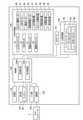
図3は、複合処理装置1の機能的構成を示す図である。
複合処理装置1は、制御部100と、記憶部110と、表示部120と、入力部130と、通信部140と、小切手印刷部150と、ロール紙印刷部160とを備える。FIG. 3 is a diagram showing a functional configuration of the combined
The
制御部100は、CPU等のプロセッサー(図示略)や、ROM、RAM、ASIC、信号処理回路等を備え、複合処理装置1の各部を制御する。制御部100は、例えばCPU等のプロセッサーが、ROMに記憶されたプログラムをRAMに読み出して処理を実行し、また例えばASICに実装された機能により処理を実行し、また例えば信号処理回路で信号処理を行って処理を実行する等、ハードウェア及びソフトウェアの協働により処理を実行する。 The
制御部100は、機能ブロックとして、状態検出部1000(検出部)と、表示制御部1001(制御部)とを備える。これらの機能ブロックは、CPUが制御プログラムに従って演算処理を実行することで実現される機能をブロックとして便宜的に示したものであり、特定のアプリケーションソフトウェアやハードウェアを示すものではない。これら機能ブロックについては、後述する。 The
記憶部110は、ハードディスクや、EEPROM、SSD(Solid State Drive)等の不揮発性メモリーを備え、各種データを書き換え可能に記憶する。 The
表示部120は、ディスプレー80を備える。本実施形態のディスプレー80は、モノクロ4階調の表示を行う表示装置であり、制御部100の制御に従って、種々の情報を表示する。また、表示部120は、複数のLEDを備え、制御部100の制御に従って、LEDを所定の態様で点灯/消灯/点滅を実行する。 The
入力部130は、複合処理装置1に設けられた操作スイッチ131等の入力装置を備え、ユーザーの入力装置に対する操作を検出し、制御部100に出力する。制御部100は、入力部130からの入力に対応する処理を実行する。 The
通信部140は、制御部100の制御で、所定の通信規格に従って外部装置であるホストコンピューター3と通信する。ホストコンピューター3は、複合処理装置1を制御する制御装置であり、例えば、デスクトップ型、ラップトップ型、或いはタブレット型のパーソナルコンピューターである。また、ホストコンピューター3は、複合処理装置1を制御するための専用のコンピューターでもよい。 The
小切手印刷部150は、小切手処理を実行する。小切手処理とは、インクジェットヘッド10による印刷の他、MICRヘッド35による読み取りや、表面CISユニット47及び裏面CISユニット48による読み取り等、小切手4の搬送に伴う処理を含む。
小切手印刷部150は、インクジェットヘッド10、ホッパー駆動モーター26、ASFモーター27、搬送モーター42、切替板駆動モーター55、MICRヘッド35、表面CISユニット47、裏面CISユニット48、ASF用紙検出器31、ホッパー位置検出器32、用紙長検出器38、中間検出器46、及び排出検出器52を備える。The
The
小切手印刷部150は、制御部100の制御に従って、インクジェットヘッド10に駆動電流を供給し、小切手4への印刷を行う。 The
また、小切手印刷部150は、制御部100の制御に従って、ホッパー駆動モーター26に駆動電流や駆動パルスを出力しホッパー25を回動させる。また、小切手印刷部150は、制御部100の制御に従って、ASFモーター27、及び搬送モーター42に駆動電流や駆動パルスを出力してこれらモーターを動作させる。この動作に伴って、これらモーターに接続されたローラーは、駆動される。また、小切手印刷部150は、制御部100の制御に従って、切替板駆動モーター55に駆動電流や駆動パルスを出力して切替板54を移動させ、小切手4の排出先を、メインポケット19a又はサブポケット19bに切り替える。 Further, the
また、小切手印刷部150は、制御部100の制御に従って、MICRヘッド35、表面CISユニット47、及び、裏面CISユニット48のそれぞれに対応する情報を読み取らせる。小切手印刷部150は、MICRヘッド35、表面CISユニット47、及び、裏面CISユニット48のそれぞれが出力する読取信号を制御部100に出力する。 Further, the
また、小切手印刷部150は、制御部100の制御に従って、ASF用紙検出器31、ホッパー位置検出器32、用紙長検出器38、中間検出器46、及び、排出検出器52のそれぞれに電流を供給して、所定周期で出力値を取得する。小切手印刷部150は、取得した出力値を制御部100に出力する。 Further, the
ロール紙印刷部160は、上述したサーマルプリンターユニット60を備え、制御部100の制御に従って、紙片を発行する。 The roll
以下の説明では、小切手印刷部150とロール紙印刷部160とを区別することなく総称する場合、印刷部と表現する。 In the following description, the
次に、制御部100の機能ブロックについて説明する。制御部100は、機能ブロックとして、状態検出部1000と、表示制御部1001とを備える。 Next, the functional block of the
状態検出部1000は、小切手印刷部150の状態、及び、ロール紙印刷部160の状態について、印刷可能状態であるか印刷不可能状態であるかを検出する。
小切手印刷部150の状態が印刷可能状態であるとは、インクジェットヘッド10による印刷が可能な状態を示し、小切手印刷部150の状態が印刷不可能状態であるとは、インクジェットヘッド10による印刷が不可能な状態を示す。例えば、インクカートリッジ45のインク残量が所定値以下となるインク切れとなった場合、小切手印刷部150の状態は、印刷不可能状態である。また、何かしらの要因でMICRヘッド35が読取不可能な状態である場合、小切手印刷部150は、小切手処理を実行できず、インクジェットヘッド10による印刷を行えない。したがって、小切手印刷部150の状態が印刷不可能状態であるとは、小切手処理が実行できないことに起因した、インクジェットヘッド10による印刷が不可能な状態を含んでもよい。
ロール紙印刷部160の状態が印刷可能状態であるとは、サーマルヘッド65による印刷が可能な状態を示し、ロール紙印刷部160の状態が印刷不可能状態であるとは、サーマルヘッド65による印刷が不可能な状態を示す。例えば、ロール紙Rの残量が所定値以下となるロール紙切れが発生した場合、ロール紙印刷部160の状態は印刷不可能状態である。The
The state of the
The state of the roll
状態検出部1000は、インク残量や、各ヘッドの状態、各モーターの状態、及び各検出器の状態を所定の方法により取得し、取得結果に基づいて小切手印刷部150の状態が印刷可能状態であるか印刷不可能状態であるかを検出する。また、状態検出部1000は、ロール紙Rの残量や、サーマルヘッド65の状態、カッターユニット66の状態等を所定の方法により取得し、取得結果に基づいてロール紙印刷部160の状態が印刷可能状態であるか印刷不可能状態であるかを検出する。 The
状態検出部1000が検出する印刷不可能状態には、復帰可能状態と復帰不可能状態が含まれる。復帰可能状態とは、ユーザーの作業により容易に解消可能な印刷不可能状態であり、例えば、インク切れやロール紙切れ等の状態である。復帰不可能状態とは、ユーザーの作業では容易に解消できず、複合処理装置1の専門家の作業が必要となる蓋然性の高い印刷不可能状態である。例えば、復帰不可能状態としては、各ヘッドの動作エラーや、各モーターの動作エラー、各検出器の動作エラー等が挙げられる。 The non-printable state detected by the
表示制御部1001は、ディスプレー80に、複合処理装置1の状態等の各種情報を表示させる。以下、表示制御部1001による表示制御を主に、複合処理装置1の動作を説明する。 The
図4は、複合処理装置1の動作を示すフローチャートである。 FIG. 4 is a flowchart showing the operation of the combined
図4に示すフローチャートの開始時点では、複合処理装置1の状態が、小切手処理部150、又はロール紙印刷部160による印刷実行を待機している待機状態であるものとする。 At the start of the flowchart shown in FIG. 4, it is assumed that the state of the combined
状態検出部1000は、小切手印刷部150、及び、ロール紙印刷部160の状態が印刷可能状態であるか印刷不可能状態であるかを検出する(ステップS1)。 The
小切手印刷部150またはロール紙印刷部160が印刷不可能状態にある場合、状態検出部1000は、さらに、小切手印刷部150またはロール紙印刷部160の状態が復帰不可能状態であるか否かを判別する(ステップS2)。 When the
小切手印刷部150またはロール紙印刷部160の状態が復帰不可能状態である場合(ステップS2:YES)、表示制御部1001はステップS3の処理を実行する。ステップS3の処理については、後述する。 When the state of the
また、小切手印刷部150及びロール紙印刷部160の状態が復帰不可能状態でない場合(ステップS2:NO)、すなわち、小切手印刷部150及びロール紙印刷部160の状態が、印刷可能状態、或いは復帰可能状態である場合、制御部100はステップS4の処理を実行する。 Further, when the states of the
制御部100は、ステップS4において、小切手印刷部150とロール紙印刷部160のいずれが選択されているかを判別する(ステップS4)。 The
印刷部の選択は、例えばホストコンピューター3から送信されるコマンドにより、所定のタイミングで行われる。例えば、ホストコンピューター3は、実行する処理に応じて、印刷部を決定し、印刷部の選択を指示するコマンドを複合処理装置1に送信する。複合処理装置1の制御部100は、受信したコマンドに応じて、複数ある印刷部から印刷を実行する1の印刷部を選択する。なお、印刷部の選択を指示するコマンドは、小切手印刷部150またはロール紙印刷部160のいずれかを指定する形態であってもよいし、印刷媒体として小切手またはロール紙を指定する形態であってもよい。例えば、コマンドにより印刷媒体として小切手が指定された場合、制御部100は小切手印刷部150を選択し、コマンドにより印刷媒体としてロール紙が指定された場合、制御部100はロール紙印刷部160を選択する。 The selection of the printing unit is performed at a predetermined timing by, for example, a command transmitted from the
小切手印刷部150及びロール紙印刷部160が、印刷を実行する印刷部として選択されていない場合(ステップS4:NO)、表示制御部1001は、ステップS1での状態検出部1000による検出結果に基づいて、複合処理装置1の状態情報をディスプレー80に表示させる。 When the
小切手印刷部150及びロール紙印刷部160の状態が印刷可能状態である場合(ステップS5:NO)、表示制御部1001は、印刷可能状態であることを示す小切手印刷部状態情報KJJ、及び印刷可能状態であることを示すロール紙印刷部状態情報RJJをディスプレー80に表示させる(ステップS6)。 When the
図5は、小切手印刷部状態情報KJJ、及びロール紙印刷部状態情報RJJの一例を示す図である。 FIG. 5 is a diagram showing an example of the check printing section status information KJJ and the roll paper printing section status information RJJ.
小切手印刷部状態情報KJJは、例えば、小切手印刷部150による印刷において消耗するインクの状態を示すインク状態情報IJJである。インク状態情報IJJは、インクを図案化した画像情報GJ1と、小切手印刷部150の状態を明示する明示情報MJ1とを含む。
また、ロール紙印刷部状態情報RJJは、例えば、ロール紙印刷部160による印刷において消耗するロール紙Rの状態を示すロール紙状態情報PJJである。ロール紙状態情報PJJは、ロール紙Rを図案化した画像情報GJ2と、ロール紙印刷部160の状態を明示する明示情報MJ2とを含む。
図5に示す明示情報MJ1、MJ2は、チェックマークで示された情報であり、小切手印刷部150、及びロール紙印刷部160の状態が印刷可能状態であることを示している。The check printing unit status information KJJ is, for example, ink status information IJJ indicating the status of ink consumed in printing by the
Further, the roll paper printing unit state information RJJ is, for example, roll paper state information PJJ indicating the state of the roll paper R that is consumed in printing by the roll
The explicit information MJ1 and MJ2 shown in FIG. 5 are the information indicated by the check marks, and indicate that the
このように、小切手印刷部状態情報KJJとロール紙印刷部状態情報RJJとを同時に表示させることで、どの印刷部がどのような状態であるかをユーザーに認識させることができる。 In this way, by displaying the check printing section status information KJJ and the roll paper printing section status information RJJ at the same time, it is possible to make the user recognize which printing section is in what state.
図5に示すように、表示制御部1001は、小切手印刷部状態情報KJJ(インク状態情報IJJ)とロール紙印刷部状態情報RJJ(ロール紙状態情報PJJ)との他に、ディスプレー80の下方に近接して配置された操作スイッチ131によって選択可能に構成されたボタンを示すボタン情報BJ1、BJ2をディスプレー80に表示させる。ボタン情報BJ1は、インクジェットヘッド10のクリーニングの実行を指示する情報であり、ディスプレー80の表示領域において、インク状態情報IJJと対応する位置に表示される。また、ボタン情報BJ2は、ロール紙Rの紙送りを指示する情報であり、ディスプレー80の表示領域において、ロール紙状態情報PJJと対応する位置に表示される。このように、ボタン情報BJ1,BJ2は、操作スイッチ131の機能を表している。 As shown in FIG. 5, the
表示制御部1001は、印刷を実行する印刷部として小切手印刷部150が選択されている場合、ボタン情報BJ1のみディスプレー80に表示させ、ロール紙印刷部160が選択されている場合、ボタン情報BJ2のみディスプレー80に表示させ、いずれの印刷部も選択されていない場合、ボタン情報BJ1、BJ2のそれぞれをディスプレー80に表示させてもよい。この場合、ユーザーは、複合処理装置1の状態について、どの印刷部が選択されているのか、或いはいずれの印刷部も選択されていないのかを容易に認識できる。
また、ボタン情報BJ1,BJ2の表示の有無は、対応する消耗品の状態に応じて選択してもよい。例えば、ボタン情報BJ1は、インク残量が所定値以下の場合には非表示またはグレーアウト表示にしてもよい。また、ボタン情報BJ2は、ロール紙の残量が所定置以下の場合には非表示またはグレーアウト表示にしてもよい。インクの残量が少ない場合にはインクジェットヘッド10のクリーニングを実行できない場合があり、ロール紙Rの残量が少ない場合にはロール紙の紙送りを実行できない場合があるため、ボタン情報BJ1、BJ2を非表示またはグレーアウト表示にすることが好ましい。The
Further, the presence / absence of the display of the button information BJ1 and BJ2 may be selected according to the state of the corresponding consumable item. For example, the button information BJ1 may be hidden or grayed out when the ink remaining amount is equal to or less than a predetermined value. Further, the button information BJ2 may be hidden or grayed out when the remaining amount of the roll paper is less than or equal to a predetermined position. If the remaining amount of ink is low, the cleaning of the
図4に示すフローチャートの説明に戻り、小切手印刷部150またはロール紙印刷部160の状態が印刷不可能状態である場合(ステップS5:YES)、表示制御部1001は、小切手印刷部状態情報KJJ、及びロール紙印刷部状態情報RJJをディスプレー80に表示させる(ステップS7)。 Returning to the description of the flowchart shown in FIG. 4, when the state of the
図6は、小切手印刷部状態情報KJJ、及びロール紙印刷部状態情報RJJの一例を示す図である。
図6では、ロール紙印刷部160の状態が印刷不可能状態である場合を例示する。FIG. 6 is a diagram showing an example of the check printing section status information KJJ and the roll paper printing section status information RJJ.
FIG. 6 illustrates a case where the roll
図6と図5とを比較して明らかな通り、図6に示すロール紙印刷部状態情報RJJ)は、記号「×」を示す明示情報MJ2を含む。「×」を示す明示情報MJ2は、ロール紙印刷部160の状態が印刷不可能状態であることを示している。
同様に、小切手印刷部150の状態が印刷不可能状態である場合には、小切手印刷部状態情報KJJの明示情報MJ1は、記号「×」となる。また、小切手印刷部150とロール紙印刷部160とが印刷不可能状態である場合には、小切手印刷部状態情報KJJの明示情報MJ1とロール紙印刷部状態情報RJJの明示情報MJ2とが、記号「×」となる。As is clear from the comparison between FIGS. 6 and 5, the roll paper printing unit state information RJJ) shown in FIG. 6 includes the explicit information MJ2 indicating the symbol “x”. The explicit information MJ2 indicating "x" indicates that the state of the roll
Similarly, when the state of the
このように、表示制御部1001は、印刷不可能状態の印刷部について、印刷部の状態が印刷不可能状態であること示す情報を、他の印刷部の状態情報と同時にディスプレー80に表示させる。これにより、ユーザーは、どの印刷部が印刷不可能状態であるかを認識できる。 As described above, the
図4に示すフローチャートの説明に戻り、ステップS1での状態検出部1000による印刷部の状態検出結果、及び、ステップS4での制御部100による印刷部の選択判別結果に基づいて、表示制御部1001は、以下のとおり、ディスプレー80に表示させる情報を変更する。 Returning to the description of the flowchart shown in FIG. 4, the
小切手印刷部150が選択されており(ステップS8:「小切手印刷部」)、各印刷部の状態が印刷可能状態である場合(ステップS9:「印刷可能状態」)、表示制御部1001は、印刷可能状態であることを示す小切手印刷部状態情報KJJ、及び印刷可能状態であることを示すロール紙印刷部状態情報RJJをディスプレー80に表示させる(ステップS10)。また、表示制御部1001は、ボタン情報BJ1、BJ2のうち、ボタン情報BJ1のみディスプレー80に表示させる。これにより、ユーザーは、各印刷部の状態が印刷可能状態であり、選択されている印刷部が小切手印刷部150であると認識できる。 When the
次いで、制御部100は、小切手処理を開始するか否かを判別する(ステップS14)。例えば、制御部100は、ホストコンピューター3から小切手処理の実行を指示する制御コマンドを受信し、ストッカー15に小切手4が収容されておりASF用紙検出器31が小切手4を検出している場合、小切手処理を開始すると判別する。制御部100は、小切手処理を開始すると判別すると(ステップS14:YES)、小切手印刷部150を制御して小切手処理を実行する(ステップS15)。小切手処理を実行しない場合には(ステップS14:NO)、処理をステップ1に移行させる。 Next, the
ステップS9の説明に戻り、小切手印刷部150が選択されており(ステップS8:「小切手印刷部」)、ロール紙印刷部160の状態が印刷不可能状態である場合(ステップS9:「ロール紙印刷部が印刷不可能状態」)、表示制御部1001は、印刷可能状態であることを示す小切手印刷部状態情報KJJ、及び、印刷不可能状態であることを示すロール紙印刷部状態情報RJJをディスプレー80に表示させる(ステップS11)。例えば、表示制御部1001は、チェックマークを示す明示情報MJ1を含む小切手印刷部状態情報KJJ、及び、記号「×」を示す明示情報MJ2を含むロール紙印刷部状態情報RJJをディスプレー80に表示させる。また、表示制御部1001は、ボタン情報BJ1をディスプレー80に表示させる。すなわち、表示制御部1001は、図6に示す各情報のうち、ボタン情報BJ2以外の情報をディスプレー80に表示させる。
これにより、ユーザーは、ロール紙印刷部160が印刷不可能状態であり、選択されている印刷部が小切手印刷部150であることを認識できる。Returning to the description of step S9, when the
As a result, the user can recognize that the roll
また、小切手印刷部150が選択されており(ステップS8:「小切手印刷部」)、小切手印刷部150の状態が印刷不可能状態である場合(ステップS9:「小切手印刷部が印刷不可能状態」)、表示制御部1001は、小切手印刷部150の印刷不可能状態に関する情報をディスプレー80に表示させる(ステップS12)。印刷不可能状態に関する情報とは、例えば解消情報KSJである。 Further, when the
図7A、図7B、図7C、及び図7Dは、印刷不可能状態に関する情報としての解消情報KSJの一例を示す図である。インク切れが原因で小切手印刷部150が印刷不可能状態となった場合の、インク切れの状態を解消する操作手順を、図7A~図7Dの順に示している。すなわち、新しいインクカートリッジ45を準備し(図7A)、複合処理装置1の本体13のインクカートリッジ収容部のカバーを開けてインクカートリッジ45を挿入し(図7B)、インクカートリッジ45の上面中央部分を押して所定位置に装填し(図7C)、インクカートリッジ収容部のカバーを閉じる(図7D)、というインクカートリッジ45を装填(又は交換)する一連の操作を、ディスプレー80に表示させる。 7A, 7B, 7C, and 7D are diagrams showing an example of the resolution information KSJ as information regarding the non-printable state. The operation procedure for resolving the out-of-ink state when the
このように、図7A~図7Dのそれぞれが示す解消情報KSJは、インク切れの状態を解消する操作を図案化した画像情報である。印刷不可能状態を解消する操作を図案化した画像情報を解消情報KSJとしてディスプレー80に表示させることで、ユーザーは、印刷不可能状態を解消する操作を認識できる。 As described above, the elimination information KSJ shown in each of FIGS. 7A to 7D is image information that is a design of an operation for eliminating the ink-out state. By displaying the image information, which is a design of the operation for resolving the non-printable state, on the
なお、表示制御部1001は、ステップS12において、図7A~図7Dに示すように印刷不可能状態を解消するために表示すべき解消情報KSJが複数ある場合、所定期間経過する度に、操作手順に従って表示を切り替えてもよい。この場合に、図7Dの表示の後、再び図7Aから表示を行うことで、図7A~図7Dの一連の表示を繰り返し行っても良い。また、表示制御部1001は、ディスプレー80に表示している解消情報KSJの操作が行われたことを検出した場合に、次に行うべき操作を示す解消情報KSJの表示に切り替えてもよい。例えば、図7Bに示す操作が行われた場合に、次に要求される操作である図7Cに示す解消情報KSJを表示するようにしてもよい。 When there are a plurality of resolution information KSJs to be displayed in order to resolve the unprintable state as shown in FIGS. 7A to 7D in step S12, the
このように、表示制御部1001は、選択されている小切手印刷部150の状態が印刷不可能状態である場合、小切手印刷部150の印刷不可能状態に関する情報をディスプレー80に表示させる。本実施形態の場合、印刷不可能状態に関する情報は、印刷不可能状態を解消するための操作手順を示す解消情報KSJである。これにより、複合処理装置1は、小切手印刷部150の印刷不可能状態を速やかに解消できるようにユーザーを支援できる。 As described above, when the selected
以上のように、表示制御部1001は、小切手印刷部150が選択されており、小切手印刷部150の状態が印刷可能状態である場合、小切手印刷部状態情報KJJ、及びロール紙印刷部状態情報RJJをディスプレー80に表示させる。また、表示制御部1001は、小切手印刷部150が選択されており、小切手印刷部150の状態が印刷不可能状態である場合、小切手印刷部150の印刷不可能状態に関する情報(解消情報KSJ)をディスプレー80に表示させる。
これにより、表示制御部1001は、選択されている小切手印刷部150の状態に応じて、ディスプレー80に表示する印刷部に関する情報(小切手印刷部状態情報KJJや、ロール紙印刷部状態情報RJJ、解消情報KSJ等を含む)を異ならせるため、小切手印刷部150及びロール紙印刷部160を有する複合処理装置1において、小切手印刷部150及びロール紙印刷部160に関する情報を適切に表示できる。
なお、ここでは、小切手印刷部150は第1印刷部に相当し、ロール紙印刷部160は第2印刷部に相当し、小切手印刷部状態情報KJJは第1印刷部状態情報に相当し、ロール紙印刷部状態情報RJJは第2印刷部状態情報に相当する。また、インクは第1消耗品に相当し、インク状態情報IJJは第1消耗品状態情報に相当し、ロール紙は第2消耗品に相当し、ロール紙状態情報PJJは第2消耗品状態情報に相当する。As described above, when the
As a result, the
Here, the
図4に示すフローチャートの説明に戻り、制御部100は、状態検出部1000の検出結果に基づいて、小切手印刷部150の印刷不可能状態が解消されたか否かを判別する(ステップS13)。制御部100は、小切手印刷部150の印刷不可能状態が解消されていないと判別した場合(ステップS13:NO)、処理をステップS12に戻す。
一方で、制御部100は、小切手印刷部150の印刷不可能状態が解消されたと判別した場合(ステップS13:YES)、処理をステップS14に移行させる。また、表示制御部1001は、小切手印刷部状態情報KJJを印刷不可能状態を示す情報から印刷可能状態を示す情報に切り替えてディスプレー80に表示する。Returning to the description of the flowchart shown in FIG. 4, the
On the other hand, when the
ステップS8の説明に戻り、ロール紙印刷部160が選択されており(ステップS8:「ロール紙印刷部」)、各印刷部が印刷可能状態である場合(ステップS16:「印刷可能状態」)、表示制御部1001は、印刷可能状態であることを示す小切手印刷部状態情報KJJ、及び印刷可能状態であることを示すロール紙印刷部状態情報RJJをディスプレー80に表示させる(ステップS17)。また、表示制御部1001は、ボタン情報BJ1、BJ2のうち、ボタン情報BJ2のみディスプレー80に表示させる。これにより、ユーザーは、各印刷部が印刷可能状態であり、選択されている印刷部がロール紙印刷部160であると認識できる。 Returning to the description of step S8, when the roll
次いで、制御部100は、文字や画像等が印刷された紙片の発行を開始するか否かを判別する(ステップS21)。例えば、制御部100は、ホストコンピューター3から紙片の発行を指示する制御コマンドまたはロール紙Rに印刷する印刷データを受信した場合、紙片の発行を開始すると判別する。制御部100は、紙片の発行を開始すると判別すると(ステップS21:YES)、ロール紙Rに文字や画像等を印刷し、ロール紙Rの印刷された部分をカットして紙片を発行する(ステップS22)。紙片の発行を実行しない場合には(ステップS21:NO)、処理をステップ1に移行させる。 Next, the
ステップS16の説明に戻り、ロール紙印刷部160が選択されており(ステップS8:「ロール紙印刷部」)、小切手印刷部150の状態が印刷不可能状態である場合(ステップS16:「小切手印刷部が印刷不可能状態」)、表示制御部1001は、印刷不可能状態であることを示す小切手印刷部状態情報KJJ、及び、印刷可能状態であることを示すロール紙印刷部状態情報RJJをディスプレー80に表示させる(ステップS18)。例えば、表示制御部1001は、記号「×」を示す明示情報MJ1を含む小切手印刷部状態情報KJJ、及び、チェックマークを示す明示情報MJ2を含むロール紙印刷部状態情報RJJをディスプレー80に表示させる。また、表示制御部1001は、ボタン情報BJ2をディスプレー80に表示させる。
これにより、ユーザーは、小切手印刷部150が印刷不可能状態であり、選択されている印刷部がロール紙印刷部160であることを認識できる。Returning to the description of step S16, when the roll
As a result, the user can recognize that the
ステップS16の説明に戻り、ロール紙印刷部160が選択されており(ステップS8:「ロール紙印刷部」)、ロール紙印刷部160の状態が印刷不可能状態である場合(ステップS16:「ロール紙印刷部が印刷不可能状態」)、表示制御部1001は、ロール紙印刷部160の印刷不可能状態に関する情報をディスプレー80に表示させる(ステップS19)。前述した通り本実施形態の場合、印刷不可能状態に関する情報は、印刷不可能状態を解消するための操作手順を示す解消情報KSJである。 Returning to the description of step S16, when the roll
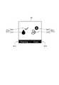
図8は、印刷不可能状態に関する情報としての解消情報KSJの一例を示す図である。 FIG. 8 is a diagram showing an example of the resolution information KSJ as information regarding the unprintable state.
ロール紙切れが原因でロール紙印刷部160が印刷不可能状態となった場合の、ロール紙切れの状態を解消する操作手順の一部を図8に示している。図8は、ロール紙切れを解消する3つの操作、すなわち、プリンターカバー61を開け(操作手順1)、ロール紙Rの先端部分をロール部分から引き出した状態でロール紙Rをロール紙収容部62に装填し(操作手順2)、プリンターカバー61を閉じる(操作手順3)、という一連の操作のうち、2つめの操作であるロール紙Rの装填に係る表示を示している。 FIG. 8 shows a part of the operation procedure for resolving the out-of-roll state when the roll
このように、図8が示す解消情報KSJは、ロール紙切れを解消する操作を図案化した画像情報である。これにより、ユーザーは印刷不可能状態を解消する操作を認識できる。また、複合処理装置1は、ロール紙印刷部160の印刷不可能状態を速やかに解消できるようにユーザーを支援できる。 As described above, the elimination information KSJ shown in FIG. 8 is image information that is a design of an operation for eliminating a roll of paper. As a result, the user can recognize the operation of resolving the non-printable state. Further, the
表示制御部1001は、ステップS19において、ステップS12と同様に、ディスプレー80に表示する解消情報KSJが複数ある場合、所定期間経過する度に、表示を切り替えてもよい。また、表示制御部1001は、ディスプレー80に表示している解消情報KSJの操作が行われたことを検出した場合に、次に行うべき操作を示す解消情報KSJの表示に切り替えてもよい。 In step S19, the
図4に示すフローチャートの説明に戻り、制御部100は、ロール紙印刷部160の印刷不可能状態が解消されたか否かを判別する(ステップS20)。制御部100は、ロール紙印刷部160の印刷不可能状態が解消されていないと判別した場合(ステップS20:NO)、処理をステップS19に戻す。
一方で、制御部100は、ロール紙印刷部160の印刷不可能状態が解消されたと判別した場合(ステップS20:YES)、処理をステップS21に移行させる。また、表示制御部1001は、ロール紙印刷部状態情報RJJを印刷不可能状態から印刷可能状態に切り替えてディスプレー80に表示する。Returning to the description of the flowchart shown in FIG. 4, the
On the other hand, when the
以上のように、表示制御部1001は、ロール紙印刷部160が選択されており、ロール紙印刷部160の状態が印刷可能状態である場合、小切手印刷部状態情報KJJ、及びロール紙印刷部状態情報RJJをディスプレー80に表示させる。また、表示制御部1001は、ロール紙印刷部160が選択されており、ロール紙印刷部160の状態が印刷不可能状態である場合、ロール紙印刷部160の印刷不可能状態に関する情報(解消情報KSJ)をディスプレー80に表示させる。
これにより、表示制御部1001は、選択されているロール紙印刷部160の状態に応じて、ディスプレー80が表示する印刷部に関する情報(小切手印刷部状態情報KJJや、ロール紙印刷部状態情報RJJ、解消情報KSJ等を含む)を異ならせるため、小切手印刷部150及びロール紙印刷部160に関する情報を適切に表示できる。
なお、ここでは、ロール紙印刷部160は第1印刷部に相当し、小切手印刷部150は第2印刷部に相当し、ロール紙印刷部状態情報RJJは第1印刷部状態情報に相当し、小切手印刷部状態情報KJJは第2印刷部状態情報に相当する。また、ロール紙Rは第1消耗品に相当し、ロール紙状態情報PJJは第1消耗品状態情報に相当し、インクは第2消耗品に相当し、インク状態情報IJJは第2消耗品状態情報に相当する。As described above, when the roll
As a result, the
Here, the roll
図4に示すフローチャートのステップS2の説明に戻り、小切手印刷部150またはロール紙印刷部160の少なくともいずれかの状態が復帰不可能状態である場合(ステップS2:YES)、表示制御部1001は、復帰不可能状態に関する情報をディスプレー80に表示させる(ステップS3)。 Returning to the description of step S2 of the flowchart shown in FIG. 4, when at least one of the
図9は、復帰不可能状態に関する情報の一例を示す図である。 FIG. 9 is a diagram showing an example of information regarding the non-recoverable state.
表示制御部1001は、復帰不可能状態に関する情報として、復帰不可能状態の要因となったエラーを識別するエラーコードECDをディスプレー80に表示させる。これにより、ユーザーは、ディスプレー80に表示されたエラーコードECDに基づいて、複合処理装置1のマニュアル等を参照し、復帰不可能状態となったエラーがどのようなエラーであるかを認識できる。 The
特に、表示制御部1001は、小切手印刷部150またはロール紙印刷部160のいずれが選択されているかに関わらず、小切手印刷部150またはロール紙印刷部160が復帰不可能状態である場合、復帰不可能状態に関する情報を表示する。すなわち、複合処理装置1は、発生したエラーの種類に応じて、印刷部の選択状態によらず、エラー情報をディスプレー80に表示する。これにより、表示制御部1001は、選択されていない印刷部が復帰不可能状態になった場合でも、ユーザーに復帰不可能状態に関する情報を確実に認識させることができる。 In particular, the
以上、説明したように、複合処理装置1は、小切手印刷部150とロール紙印刷部160とを有し、選択されたいずれか一方により印刷を実行する。複合処理装置1は、小切手印刷部150、及びロール紙印刷部160の状態が印刷可能状態であるか印刷不可能状態であるかを検出する状態検出部1000と、情報を表示するディスプレー80と、状態検出部1000の検出結果に基づいて、小切手印刷部状態情報KJJ、及びロール紙印刷部状態情報RJJをディスプレー80に表示させる表示制御部1001と、を備える。
表示制御部1001は、小切手印刷部150(第1印刷部)が選択されており、小切手印刷部150が印刷可能状態である場合、小切手印刷部状態情報KJJ(第1印刷部状態情報)、及びロール紙印刷部状態情報RJJ(第2印刷部状態情報)をディスプレー80に表示させ、小切手印刷部150が選択されており、小切手印刷部150が印刷不可能状態である場合、小切手印刷部150の印刷不可能状態に関する情報をディスプレー80に表示させる。
また、表示制御部1001は、ロール紙印刷部160(第1印刷部)が選択されており、ロール紙印刷部160が印刷可能状態である場合、ロール紙印刷部状態情報RJJ(第1印刷部状態情報)、及び小切手印刷部状態情報KJJ(第2印刷部状態情報)をディスプレー80に表示させ、ロール紙印刷部160が選択されており、ロール紙印刷部160が印刷不可能状態である場合、ロール紙印刷部160の印刷不可能状態に関する情報をディスプレー80に表示させる。As described above, the
When the check printing unit 150 (first printing unit) is selected for the
When the roll paper printing unit 160 (first printing unit) is selected for the
この構成によれば、選択されている印刷部の状態に応じて、ディスプレー80が表示する印刷部に関する情報を異ならせることができ、小切手印刷部150、及びロール紙印刷部160を有する複合処理装置1において、印刷部に関する情報を適切に表示できる。 According to this configuration, the information about the printing unit displayed by the
また、印刷不可能状態は、復帰可能状態と復帰不可能状態とを含む。表示制御部1001は、小切手印刷部150またはロール紙印刷部160の状態が復帰不可能状態である場合、小切手印刷部150、及びロール紙印刷部160のいずれが選択されているかに関わらず、小切手印刷部150またはロール紙印刷部160の復帰不可能状態に関する情報を前記ディスプレー80に表示させる。 Further, the non-printable state includes a recoverable state and a non-recoverable state. When the state of the
この構成によれば、小切手印刷部150、及びロール紙印刷部160のいずれが選択されているかに関わらず、復帰不可能状態に関する情報をディスプレー80に表示するため、表示制御部1001は、ユーザーに復帰不可能状態に関する情報を確実に認識させることができる。 According to this configuration, regardless of whether the
また、印刷不可能状態に関する情報は、印刷不可能状態の解消に関する情報である。 Further, the information regarding the non-printable state is information regarding the elimination of the non-printable state.
この構成によれば、表示制御部1001は、小切手印刷部150の状態が印刷不可能状態である場合、小切手印刷部150の印刷不可能状態の解消に関する情報(図7A~図7Dの解消情報KSJ)を表示し、ロール紙印刷部160の状態が印刷不可能状態である場合、ロール紙印刷部160の印刷不可能状態の解消に関する情報(図8の解消情報KSJ)を表示する。そのため、複合処理装置1は、速やかに印刷部の印刷不可能状態を解消できるようにユーザーを支援できる。 According to this configuration, when the state of the
また、小切手印刷部状態情報KJJは、小切手印刷部150による印刷において消耗するインクの状態を示すインク状態情報IJJである。小切手印刷部150が第1印刷部に相当する場合、インクは第1消耗品に相当し、インク状態情報IJJは第1消耗品状態情報に相当する。また、小切手印刷部150が第2印刷部に相当する場合、インクは第2消耗品に相当し、インク状態情報IJJは第2消耗品状態情報に相当する。
また、ロール紙印刷部状態情報RJJは、ロール紙印刷部160による印刷において消耗するロール紙Rの状態を示すロール紙状態情報PJJである。ロール紙印刷部160が第1印刷部に相当する場合、ロール紙Rは第1消耗品に相当し、ロール紙状態情報PJJは第1消耗品状態情報に相当する。また、ロール紙印刷部160が第2印刷部に相当する場合、ロール紙Rは第2消耗品に相当し、ロール紙状態情報PJJは第2消耗品状態情報に相当する。
この構成によれば、ユーザーは消耗品の状態を認識できる。Further, the check printing unit status information KJJ is ink status information IJJ indicating the status of ink consumed in printing by the
Further, the roll paper printing unit state information RJJ is roll paper state information PJJ indicating the state of the roll paper R that is consumed in printing by the roll
According to this configuration, the user can recognize the state of consumables.
このように、複合処理装置1は、選択された印刷部が印刷可能状態であるとき、他の印刷部が第2のエラー状態、例えば復帰不可能な印刷不可能状態にある場合を除いて、各印刷部の状態をディスプレー80に同時に表示する。
また、複合処理装置1は、選択された印刷部が第1のエラー状態、例えば復帰可能な印刷不可能状態にあるとき、第1のエラー状態の解消に関する情報をディスプレー80に表示する。なお、非選択の印刷部が第1のエラー状態にあっても、第1のエラー状態の解消に関する情報をディスプレー80に表示することはない。選択された印刷部は、非選択の印刷部の第1のエラー状態が解消されたか否かに因らず、動作可能であるため、複合処理装置1は、非選択の印刷部の第1のエラー状態の解消に関する情報はディスプレー80に表示しない。第1のエラー状態にある印刷部が選択されたときに、第1のエラー状態の解消に関する情報をディスプレー80に表示させればよい。
また、複合処理装置1は、印刷部が第2のエラー状態にあるとき、印刷部の選択状態に因らず、第2のエラー状態にあることを示すエラー情報をディスプレー80に表示する。As described above, when the selected printing unit is in the printable state, the combined
Further, when the selected printing unit is in a first error state, for example, a recoverable non-printable state, the combined
Further, when the printing unit is in the second error state, the
上述した実施形態は、あくまでも本発明の一態様を示すものであり、本発明の範囲内で任意に変形および応用が可能である。 The above-described embodiment shows only one aspect of the present invention, and can be arbitrarily modified and applied within the scope of the present invention.
例えば、上述した実施形態では、複合処理装置1が有する印刷部として小切手印刷部150及びロール紙印刷部160を例示した。しかしながら、複合処理装置は、複数の印刷部を有すればよく、印刷部の個数や印刷形式、印刷媒体の種類等は限定されない。 For example, in the above-described embodiment, the
また、上述した実施形態では、小切手印刷部150とロール紙印刷部160のいずれも選択されていない場合(ステップS4:NO)を想定したが、ホストコンピューター3から印刷部の選択を指示するコマンドを受信していない場合には、予め定められたいずれかの印刷部が選択されていることとしてもよい。例えば、小切手印刷部150が選択された状態を初期値としてもよい。この場合には、上述したステップS5~S7の処理は不要となる。 Further, in the above-described embodiment, it is assumed that neither the
また、例えば、上述した複合処理装置1の制御方法(プリンターの制御方法)が、複合処理装置1が備えるコンピューター、又は、複合処理装置1に接続される外部装置を用いて実現される場合、本発明を、当該方法を実現するためにコンピューターが実行するプログラム、このプログラムをコンピューターで読み取り可能に記録した記録媒体、或いは、このプログラムを伝送する伝送媒体の態様で構成することも可能である。 Further, for example, when the above-mentioned control method of the combined processing device 1 (printer control method) is realized by using a computer included in the combined
また、制御部100の機能は、複数のプロセッサー、又は、半導体チップにより実現してもよい。例えば、制御部100が、SoC(System-on-a-Chip)やMCU(Micro Control Unit)、FPGA(Field-Programmable Gate Array)等の副処理装置(co-processor)をさらに備える構成であってもよい。また、制御部100は、CPU及び副処理装置の双方を協働させるか、あるいは双方のうちの一方を選択的に用いて各種の制御を行ってもよい。 Further, the function of the
また、例えば、図4の処理単位は、複合処理装置1の処理を理解容易にするために、主な処理内容に応じて分割したものであり、処理単位の分割の仕方や名称によって、本発明が限定されることはない。処理内容に応じて、さらに多くの処理単位に分割してもよい。また、1つの処理単位がさらに多くの処理を含むように分割してもよい。また、その処理の順番は、本発明の趣旨に支障のない範囲で適宜に入れ替えてもよい。 Further, for example, the processing unit of FIG. 4 is divided according to the main processing contents in order to make the processing of the
また、図3に示した各機能部は機能的構成を示すものであって、具体的な実装形態は特に限定されない。つまり、必ずしも各機能部に個別に対応するハードウェアが実装される必要はなく、一つのプロセッサーがプログラムを実行することで複数の機能部の機能を実現する構成とすることも勿論可能である。また、上述した実施形態においてソフトウェアで実現される機能の一部をハードウェアとしてもよく、或いは、ハードウェアで実現される機能の一部をソフトウェアで実現してもよい。その他、複合処理装置1の他の各部の具体的な細部構成についても、本発明の趣旨を逸脱しない範囲で任意に変更可能である。 Further, each functional unit shown in FIG. 3 shows a functional configuration, and a specific mounting form is not particularly limited. That is, it is not always necessary to implement hardware corresponding to each functional unit individually, and it is of course possible to realize the functions of a plurality of functional units by executing a program by one processor. Further, a part of the functions realized by the software in the above-described embodiment may be realized by the hardware, or a part of the functions realized by the hardware may be realized by the software. In addition, the specific detailed configuration of each of the other parts of the
1…複合処理装置(プリンター)、3…ホストコンピューター、10…インクジェットヘッド、22…MCRヘッド、26…ホッパー駆動モーター、27…ASFモーター、31…ASF用紙検出器、32…ホッパー位置検出器、35…MICRヘッド、36…MICRローラー、38…用紙長検出器、42…搬送モーター、46…中間検出器、47…表面CISユニット、48…裏面CISユニット、52…排出検出器、55…切替板駆動モーター、60…サーマルプリンターユニット、65…サーマルヘッド、66…カッターユニット、80…ディスプレー、100…制御部、110…記憶部、130…入力部、140…通信部、150…小切手印刷部(第1印刷部、第2印刷部)、160…ロール紙印刷部(第1印刷部、第2印刷部)、1000…状態検出部(検出部)、IJJ…インク状態情報(第1消耗品状態情報、第2消耗品状態情報)、KJJ…小切手印刷部状態情報(第1印刷部状態情報、第2印刷部状態情報)、KSJ…解消情報(解消に関する情報)、PJJ…ロール紙状態情報(第1消耗品状態情報、第2消耗品状態情報)、R…ロール紙(第1消耗品、第2消耗品)、RJJ…ロール紙印刷部状態情報(第1印刷部状態情報、第2印刷部状態情報)。 1 ... Composite processing device (printer), 3 ... Host computer, 10 ... Inkjet head, 22 ... MCR head, 26 ... Hopper drive motor, 27 ... ASF motor, 31 ... ASF paper detector, 32 ... Hopper position detector, 35 ... MICR head, 36 ... MICR roller, 38 ... Paper length detector, 42 ... Conveyor motor, 46 ... Intermediate detector, 47 ... Front surface CIS unit, 48 ... Back surface CIS unit, 52 ... Emission detector, 55 ... Switching plate drive Motor, 60 ... Thermal printer unit, 65 ... Thermal head, 66 ... Cutter unit, 80 ... Display, 100 ... Control unit, 110 ... Storage unit, 130 ... Input unit, 140 ... Communication unit, 150 ... Check printing unit (1st) Printing unit, 2nd printing unit), 160 ... Roll paper printing unit (1st printing unit, 2nd printing unit), 1000 ... Status detection unit (detection unit), IJJ ... Ink status information (1st consumables status information, 2nd consumables status information), KJJ ... check printing section status information (1st printing section status information, 2nd printing section status information), KSJ ... resolution information (information regarding resolution), PJJ ... roll paper status information (1st) Consumables status information, 2nd consumables status information), R ... Roll paper (1st consumables, 2nd consumables), RJJ ... Roll paper Printing section status information (1st printing section status information, 2nd printing section status) information).
Claims (6)
Translated fromJapanese外部装置と通信可能な通信部と、
前記第1印刷部、及び前記第2印刷部の状態が印刷可能状態であるか印刷不可能状態であるかを検出する検出部と、
情報を表示するディスプレーと、
前記検出部の検出結果に基づいて、前記第1印刷部の状態を示す第1印刷部状態情報、及び前記第2印刷部の状態を示す第2印刷部状態情報を前記ディスプレーに表示させる制御部と、を備え、
前記制御部は、
前記外部装置から受信したコマンドによって前記第1印刷部が選択されており、前記第1印刷部の状態が前記印刷可能状態である場合、前記第1印刷部状態情報、及び前記第2印刷部状態情報の両方を前記ディスプレーに表示させ、
前記外部装置から受信したコマンドによって前記第1印刷部が選択されており、前記第1印刷部の状態が前記印刷不可能状態である場合、前記第1印刷部の前記印刷不可能状態に関する情報を前記ディスプレーに表示させる、
プリンター。A printer having a first printing unit and a second printing unit, and performing printing by one of the selected units.
A communication unit that can communicate with external devices,
A detection unit that detects whether the state of the first printing unit and the second printing unit is a printable state or a printable state, and
A display that displays information and
Based on the detection result of the detection unit, the control unit that displays the state information of the first printing unit indicating the state of the first printing unit and the state information of the second printing unit indicating the state of the second printing unit on the display. And with
The control unit
When the first printing unit is selectedby a command received from the external device and the state of the first printing unit is the printable state, the first printing unit status information and the second printing unit state Displayboth of the information on the display
When the first printing unit is selectedby a command received from the external device and the state of the first printing unit is the unprintable state, information regarding the unprintable state of the first printing unit is displayed. Displayed on the display
printer.
前記制御部は、前記第1印刷部または前記第2印刷部の状態が前記復帰不可能状態である場合、前記第1印刷部、及び前記第2印刷部のいずれが選択されているかに関わらず、前記第1印刷部または前記第2印刷部の前記復帰不可能状態に関する情報を前記ディスプレーに表示させる、
請求項1に記載のプリンター。The non-printable state includes a recoverable state and a non-recoverable state.
When the state of the first printing unit or the second printing unit is the irreversible state, the control unit may select either the first printing unit or the second printing unit. , Information on the non-recoverable state of the first printing unit or the second printing unit is displayed on the display.
The printer according to claim 1.
請求項1又は2に記載のプリンター。The information regarding the non-printable state is information regarding the elimination of the non-printable state.
The printer according to claim 1 or 2.
前記第2印刷部状態情報は、前記第2印刷部による印刷において消耗する第2消耗品の状態を示す第2消耗品状態情報である、
請求項1から3のいずれか一項に記載のプリンター。The first printing unit status information is first consumables status information indicating the status of the first consumables that are consumed in printing by the first printing unit.
The second printing unit status information is second consumables status information indicating the status of the second consumables that are consumed in printing by the second printing unit.
The printer according to any one of claims 1 to 3.
前記検出部の検出結果に基づいて、前記第1印刷部の動作を指示するための情報であって、選択可能に構成された第1情報と、前記第2印刷部の動作を指示するための情報であって、選択可能に構成された第2情報を前記ディスプレーに表示させ、Information for instructing the operation of the first printing unit based on the detection result of the detection unit, the first information configured to be selectable, and the information for instructing the operation of the second printing unit. The second information, which is information and is configured to be selectable, is displayed on the display.
前記外部装置から受信したコマンドによって前記第1印刷部が選択されており、前記第2印刷部の状態が前記印刷不可能状態である場合、前記第2情報を非表示にして、前記第1情報を表示させる、When the first printing unit is selected by a command received from the external device and the state of the second printing unit is the non-printable state, the second information is hidden and the first information is displayed. To display,
請求項1に記載のプリンター。The printer according to claim 1.
前記第1印刷部または前記第2印刷部のいずれで印刷するかを選択し、
前記第1印刷部、及び前記第2印刷部の状態が印刷可能状態であるか印刷不可能状態であるかを検出し、
外部装置から受信したコマンドによって前記第1印刷部が選択されており、前記第1印刷部の状態が前記印刷可能状態である場合、前記第1印刷部の状態を示す第1印刷部状態情報、及び前記第2印刷部の状態を示す第2印刷部状態情報の両方をディスプレーに表示させ、
前記外部装置から受信したコマンドによって前記第1印刷部が選択されており、前記第1印刷部の状態が前記印刷不可能状態である場合、前記第1印刷部の前記印刷不可能状態に関する情報を前記ディスプレーに表示させる、
プリンターの制御方法。It is a control method of a printer having a first printing unit and a second printing unit.
Select whether to print in the first printing section or the second printing section.
It is detected whether the state of the first printing unit and the second printing unit is a printable state or a printable state, and the state is detected.
When the first printing unit is selectedby a command received from an external device and the state of the first printing unit is the printable state, the first printing unit status information indicating the state of the first printing unit, And the second print section status informationindicating the state of the second print section is displayed on the display.
When the first printing unit is selectedby a command received from the external device and the state of the first printing unit is the unprintable state, information regarding the unprintable state of the first printing unit is displayed. Displayed on the display
How to control the printer.
Priority Applications (2)
| Application Number | Priority Date | Filing Date | Title |
|---|---|---|---|
| JP2018011333AJP7010026B2 (en) | 2018-01-26 | 2018-01-26 | Printer and printer control method |
| US16/256,244US10606529B2 (en) | 2018-01-26 | 2019-01-24 | Printer and method for controlling printer |
Applications Claiming Priority (1)
| Application Number | Priority Date | Filing Date | Title |
|---|---|---|---|
| JP2018011333AJP7010026B2 (en) | 2018-01-26 | 2018-01-26 | Printer and printer control method |
Publications (2)
| Publication Number | Publication Date |
|---|---|
| JP2019127000A JP2019127000A (en) | 2019-08-01 |
| JP7010026B2true JP7010026B2 (en) | 2022-01-26 |
Family
ID=67393434
Family Applications (1)
| Application Number | Title | Priority Date | Filing Date |
|---|---|---|---|
| JP2018011333AActiveJP7010026B2 (en) | 2018-01-26 | 2018-01-26 | Printer and printer control method |
Country Status (2)
| Country | Link |
|---|---|
| US (1) | US10606529B2 (en) |
| JP (1) | JP7010026B2 (en) |
Citations (5)
| Publication number | Priority date | Publication date | Assignee | Title |
|---|---|---|---|---|
| JP2002127547A (en) | 2000-10-26 | 2002-05-08 | Riso Kagaku Corp | Multi-layer printing device |
| JP2002219840A (en) | 2001-01-26 | 2002-08-06 | Matsushita Electric Ind Co Ltd | Image recording device |
| JP2013052571A (en) | 2011-09-02 | 2013-03-21 | Toshiba Tec Corp | Printer and printing method |
| JP2015167312A (en) | 2014-03-04 | 2015-09-24 | キヤノン株式会社 | Image forming apparatus |
| JP2018001458A (en) | 2016-06-28 | 2018-01-11 | 株式会社沖データ | Image formation apparatus and failure notification system |
Family Cites Families (4)
| Publication number | Priority date | Publication date | Assignee | Title |
|---|---|---|---|---|
| JPH08310046A (en)* | 1995-05-18 | 1996-11-26 | Brother Ind Ltd | Recording device |
| US20050024411A1 (en)* | 2003-05-30 | 2005-02-03 | Hitachi Printing Solutions, Ltd. | Printer system |
| US8351071B2 (en)* | 2006-01-10 | 2013-01-08 | Canon Kabushiki Kaisha | Print control apparatus, print apparatus, print system, print method, and storage medium |
| US9463647B1 (en)* | 2015-07-15 | 2016-10-11 | Toshiba Tec Kabushiki Kaisha | Printer and method for operating the same |
- 2018
- 2018-01-26JPJP2018011333Apatent/JP7010026B2/enactiveActive
- 2019
- 2019-01-24USUS16/256,244patent/US10606529B2/enactiveActive
Patent Citations (5)
| Publication number | Priority date | Publication date | Assignee | Title |
|---|---|---|---|---|
| JP2002127547A (en) | 2000-10-26 | 2002-05-08 | Riso Kagaku Corp | Multi-layer printing device |
| JP2002219840A (en) | 2001-01-26 | 2002-08-06 | Matsushita Electric Ind Co Ltd | Image recording device |
| JP2013052571A (en) | 2011-09-02 | 2013-03-21 | Toshiba Tec Corp | Printer and printing method |
| JP2015167312A (en) | 2014-03-04 | 2015-09-24 | キヤノン株式会社 | Image forming apparatus |
| JP2018001458A (en) | 2016-06-28 | 2018-01-11 | 株式会社沖データ | Image formation apparatus and failure notification system |
Also Published As
| Publication number | Publication date |
|---|---|
| US20190235808A1 (en) | 2019-08-01 |
| JP2019127000A (en) | 2019-08-01 |
| US10606529B2 (en) | 2020-03-31 |
Similar Documents
| Publication | Publication Date | Title |
|---|---|---|
| JP5803504B2 (en) | Medium processing apparatus and method for controlling medium processing apparatus | |
| JP2010221603A (en) | Printing device | |
| US20070231043A1 (en) | Label-printing apparatus and label-printing program recorded on a computer readable recording medium | |
| JP5974499B2 (en) | RECORDING DEVICE, CONTROL DEVICE, AND RECORDING DEVICE CONTROL METHOD | |
| JP7010026B2 (en) | Printer and printer control method | |
| JP2013082202A (en) | Medium processing device, and method for controlling the same | |
| CN103029433B (en) | Multifunction device and method of controlling a multifunction device | |
| JP7031328B2 (en) | Printing device and control method of printing device | |
| BR102012018164A2 (en) | media processing device, check processing device and method for controlling a media processing device | |
| US9180685B1 (en) | Printer apparatus | |
| CN110936733B (en) | Printer and control method, computer-readable storage medium, electronic device | |
| JP2013071414A (en) | Medium treatment apparatus, method for controlling the same, and program | |
| WO2010050245A1 (en) | Printing apparatus and printing method | |
| JP2016038611A (en) | Recording system, information setting method, and recording apparatus | |
| JP4534467B2 (en) | Printing method | |
| JP5899750B2 (en) | Medium processing apparatus, method for controlling medium processing apparatus, and program | |
| JP6992409B2 (en) | Printing device and control method of printing device | |
| JP2013146939A (en) | Medium processing apparatus, and method for controlling the same | |
| JP2013077187A (en) | Medium processing device, control method of medium processing device, and program | |
| JP2013021489A (en) | Reading apparatus, reading apparatus control method, and storage medium | |
| JP5924126B2 (en) | Medium processing apparatus and POS system | |
| JP5906638B2 (en) | Medium processing apparatus, method for controlling medium processing apparatus, and program | |
| JP5811745B2 (en) | Medium processing apparatus, method for controlling medium processing apparatus, and program | |
| JP2013026763A (en) | Reader, control method of the same, and program | |
| JP2000036068A (en) | Printing device |
Legal Events
| Date | Code | Title | Description |
|---|---|---|---|
| A621 | Written request for application examination | Free format text:JAPANESE INTERMEDIATE CODE: A621 Effective date:20201106 | |
| A977 | Report on retrieval | Free format text:JAPANESE INTERMEDIATE CODE: A971007 Effective date:20211007 | |
| A131 | Notification of reasons for refusal | Free format text:JAPANESE INTERMEDIATE CODE: A131 Effective date:20211012 | |
| A521 | Request for written amendment filed | Free format text:JAPANESE INTERMEDIATE CODE: A523 Effective date:20211203 | |
| TRDD | Decision of grant or rejection written | ||
| A01 | Written decision to grant a patent or to grant a registration (utility model) | Free format text:JAPANESE INTERMEDIATE CODE: A01 Effective date:20211214 | |
| A61 | First payment of annual fees (during grant procedure) | Free format text:JAPANESE INTERMEDIATE CODE: A61 Effective date:20211227 | |
| R150 | Certificate of patent or registration of utility model | Ref document number:7010026 Country of ref document:JP Free format text:JAPANESE INTERMEDIATE CODE: R150 |