JP7009960B2 - A method of vaporizing the fluid discharged by a heat generating element, a vaporizer, and a discharge head. - Google Patents
A method of vaporizing the fluid discharged by a heat generating element, a vaporizer, and a discharge head.Download PDFInfo
- Publication number
- JP7009960B2 JP7009960B2JP2017231725AJP2017231725AJP7009960B2JP 7009960 B2JP7009960 B2JP 7009960B2JP 2017231725 AJP2017231725 AJP 2017231725AJP 2017231725 AJP2017231725 AJP 2017231725AJP 7009960 B2JP7009960 B2JP 7009960B2
- Authority
- JP
- Japan
- Prior art keywords
- heat generating
- generating element
- fluid
- layer
- surface area
- Prior art date
- Legal status (The legal status is an assumption and is not a legal conclusion. Google has not performed a legal analysis and makes no representation as to the accuracy of the status listed.)
- Active
Links
- 239000012530fluidSubstances0.000titleclaimsdescription71
- 230000008016vaporizationEffects0.000titleclaimsdescription31
- 239000006200vaporizerSubstances0.000titleclaimsdescription30
- 238000000034methodMethods0.000titleclaimsdescription15
- 239000010410layerSubstances0.000claimsdescription84
- 238000010438heat treatmentMethods0.000claimsdescription47
- 239000011241protective layerSubstances0.000claimsdescription30
- 238000009834vaporizationMethods0.000claimsdescription21
- 239000000758substrateSubstances0.000claimsdescription9
- 238000007599dischargingMethods0.000claimsdescription4
- 230000003213activating effectEffects0.000claims1
- 239000000919ceramicSubstances0.000description22
- 238000010521absorption reactionMethods0.000description12
- 239000000463materialSubstances0.000description11
- 239000007788liquidSubstances0.000description7
- 239000011521glassSubstances0.000description6
- 229910052751metalInorganic materials0.000description6
- 239000002184metalSubstances0.000description6
- 238000004519manufacturing processMethods0.000description5
- PNEYBMLMFCGWSK-UHFFFAOYSA-Naluminium oxideInorganic materials[O-2].[O-2].[O-2].[Al+3].[Al+3]PNEYBMLMFCGWSK-UHFFFAOYSA-N0.000description4
- 238000010586diagramMethods0.000description3
- ZOKXTWBITQBERF-UHFFFAOYSA-NMolybdenumChemical compound[Mo]ZOKXTWBITQBERF-UHFFFAOYSA-N0.000description2
- PXHVJJICTQNCMI-UHFFFAOYSA-NNickelChemical compound[Ni]PXHVJJICTQNCMI-UHFFFAOYSA-N0.000description2
- VYPSYNLAJGMNEJ-UHFFFAOYSA-NSilicium dioxideChemical compoundO=[Si]=OVYPSYNLAJGMNEJ-UHFFFAOYSA-N0.000description2
- PCEXQRKSUSSDFT-UHFFFAOYSA-N[Mn].[Mo]Chemical compound[Mn].[Mo]PCEXQRKSUSSDFT-UHFFFAOYSA-N0.000description2
- 238000005422blastingMethods0.000description2
- 238000010329laser etchingMethods0.000description2
- 229910052750molybdenumInorganic materials0.000description2
- 239000011733molybdenumSubstances0.000description2
- 229920003023plasticPolymers0.000description2
- 239000004033plasticSubstances0.000description2
- 239000002002slurrySubstances0.000description2
- 229910001220stainless steelInorganic materials0.000description2
- 239000010935stainless steelSubstances0.000description2
- WFKWXMTUELFFGS-UHFFFAOYSA-NtungstenChemical compound[W]WFKWXMTUELFFGS-UHFFFAOYSA-N0.000description2
- 239000010937tungstenSubstances0.000description2
- 229910052721tungstenInorganic materials0.000description2
- 229910052582BNInorganic materials0.000description1
- PZNSFCLAULLKQX-UHFFFAOYSA-NBoron nitrideChemical compoundN#BPZNSFCLAULLKQX-UHFFFAOYSA-N0.000description1
- OKTJSMMVPCPJKN-UHFFFAOYSA-NCarbonChemical compound[C]OKTJSMMVPCPJKN-UHFFFAOYSA-N0.000description1
- 229910052581Si3N4Inorganic materials0.000description1
- 229910000831SteelInorganic materials0.000description1
- 230000015572biosynthetic processEffects0.000description1
- 238000009835boilingMethods0.000description1
- 229910052799carbonInorganic materials0.000description1
- 239000004020conductorSubstances0.000description1
- PMHQVHHXPFUNSP-UHFFFAOYSA-Mcopper(1+);methylsulfanylmethane;bromideChemical compoundBr[Cu].CSCPMHQVHHXPFUNSP-UHFFFAOYSA-M0.000description1
- 238000012377drug deliveryMethods0.000description1
- 239000003571electronic cigaretteSubstances0.000description1
- 238000010574gas phase reactionMethods0.000description1
- 229920001903high density polyethylenePolymers0.000description1
- 239000004700high-density polyethyleneSubstances0.000description1
- 238000007373indentationMethods0.000description1
- 150000002739metalsChemical class0.000description1
- 238000000465mouldingMethods0.000description1
- 229910052759nickelInorganic materials0.000description1
- 150000004767nitridesChemical class0.000description1
- 229920000515polycarbonatePolymers0.000description1
- 239000004417polycarbonateSubstances0.000description1
- 239000004800polyvinyl chlorideSubstances0.000description1
- 229920000915polyvinyl chloridePolymers0.000description1
- 239000011148porous materialSubstances0.000description1
- 239000000377silicon dioxideSubstances0.000description1
- HQVNEWCFYHHQES-UHFFFAOYSA-Nsilicon nitrideChemical compoundN12[Si]34N5[Si]62N3[Si]51N64HQVNEWCFYHHQES-UHFFFAOYSA-N0.000description1
- 229910052709silverInorganic materials0.000description1
- 239000004332silverSubstances0.000description1
- 238000005245sinteringMethods0.000description1
- 239000007787solidSubstances0.000description1
- 239000010959steelSubstances0.000description1
- 239000000126substanceSubstances0.000description1
- 230000003746surface roughnessEffects0.000description1
- 229910000811surgical stainless steelInorganic materials0.000description1
- 238000002560therapeutic procedureMethods0.000description1
- 239000011800void materialSubstances0.000description1
Images


Classifications
- A—HUMAN NECESSITIES
- A61—MEDICAL OR VETERINARY SCIENCE; HYGIENE
- A61M—DEVICES FOR INTRODUCING MEDIA INTO, OR ONTO, THE BODY; DEVICES FOR TRANSDUCING BODY MEDIA OR FOR TAKING MEDIA FROM THE BODY; DEVICES FOR PRODUCING OR ENDING SLEEP OR STUPOR
- A61M15/00—Inhalators
- A61M15/06—Inhaling appliances shaped like cigars, cigarettes or pipes
- F—MECHANICAL ENGINEERING; LIGHTING; HEATING; WEAPONS; BLASTING
- F22—STEAM GENERATION
- F22B—METHODS OF STEAM GENERATION; STEAM BOILERS
- F22B1/00—Methods of steam generation characterised by form of heating method
- F22B1/28—Methods of steam generation characterised by form of heating method in boilers heated electrically
- F22B1/287—Methods of steam generation characterised by form of heating method in boilers heated electrically with water in sprays or in films
- A—HUMAN NECESSITIES
- A24—TOBACCO; CIGARS; CIGARETTES; SIMULATED SMOKING DEVICES; SMOKERS' REQUISITES
- A24F—SMOKERS' REQUISITES; MATCH BOXES; SIMULATED SMOKING DEVICES
- A24F40/00—Electrically operated smoking devices; Component parts thereof; Manufacture thereof; Maintenance or testing thereof; Charging means specially adapted therefor
- A24F40/40—Constructional details, e.g. connection of cartridges and battery parts
- A24F40/46—Shape or structure of electric heating means
- A—HUMAN NECESSITIES
- A24—TOBACCO; CIGARS; CIGARETTES; SIMULATED SMOKING DEVICES; SMOKERS' REQUISITES
- A24F—SMOKERS' REQUISITES; MATCH BOXES; SIMULATED SMOKING DEVICES
- A24F40/00—Electrically operated smoking devices; Component parts thereof; Manufacture thereof; Maintenance or testing thereof; Charging means specially adapted therefor
- A24F40/40—Constructional details, e.g. connection of cartridges and battery parts
- A24F40/48—Fluid transfer means, e.g. pumps
- A24F40/485—Valves; Apertures
- A—HUMAN NECESSITIES
- A61—MEDICAL OR VETERINARY SCIENCE; HYGIENE
- A61M—DEVICES FOR INTRODUCING MEDIA INTO, OR ONTO, THE BODY; DEVICES FOR TRANSDUCING BODY MEDIA OR FOR TAKING MEDIA FROM THE BODY; DEVICES FOR PRODUCING OR ENDING SLEEP OR STUPOR
- A61M11/00—Sprayers or atomisers specially adapted for therapeutic purposes
- A61M11/04—Sprayers or atomisers specially adapted for therapeutic purposes operated by the vapour pressure of the liquid to be sprayed or atomised
- A61M11/041—Sprayers or atomisers specially adapted for therapeutic purposes operated by the vapour pressure of the liquid to be sprayed or atomised using heaters
- A61M11/042—Sprayers or atomisers specially adapted for therapeutic purposes operated by the vapour pressure of the liquid to be sprayed or atomised using heaters electrical
- A—HUMAN NECESSITIES
- A61—MEDICAL OR VETERINARY SCIENCE; HYGIENE
- A61M—DEVICES FOR INTRODUCING MEDIA INTO, OR ONTO, THE BODY; DEVICES FOR TRANSDUCING BODY MEDIA OR FOR TAKING MEDIA FROM THE BODY; DEVICES FOR PRODUCING OR ENDING SLEEP OR STUPOR
- A61M15/00—Inhalators
- A61M15/0001—Details of inhalators; Constructional features thereof
- A61M15/0021—Mouthpieces therefor
- F—MECHANICAL ENGINEERING; LIGHTING; HEATING; WEAPONS; BLASTING
- F17—STORING OR DISTRIBUTING GASES OR LIQUIDS
- F17C—VESSELS FOR CONTAINING OR STORING COMPRESSED, LIQUEFIED OR SOLIDIFIED GASES; FIXED-CAPACITY GAS-HOLDERS; FILLING VESSELS WITH, OR DISCHARGING FROM VESSELS, COMPRESSED, LIQUEFIED, OR SOLIDIFIED GASES
- F17C13/00—Details of vessels or of the filling or discharging of vessels
- F—MECHANICAL ENGINEERING; LIGHTING; HEATING; WEAPONS; BLASTING
- F17—STORING OR DISTRIBUTING GASES OR LIQUIDS
- F17C—VESSELS FOR CONTAINING OR STORING COMPRESSED, LIQUEFIED OR SOLIDIFIED GASES; FIXED-CAPACITY GAS-HOLDERS; FILLING VESSELS WITH, OR DISCHARGING FROM VESSELS, COMPRESSED, LIQUEFIED, OR SOLIDIFIED GASES
- F17C7/00—Methods or apparatus for discharging liquefied, solidified, or compressed gases from pressure vessels, not covered by another subclass
- F17C7/02—Discharging liquefied gases
- F17C7/04—Discharging liquefied gases with change of state, e.g. vaporisation
- H—ELECTRICITY
- H05—ELECTRIC TECHNIQUES NOT OTHERWISE PROVIDED FOR
- H05B—ELECTRIC HEATING; ELECTRIC LIGHT SOURCES NOT OTHERWISE PROVIDED FOR; CIRCUIT ARRANGEMENTS FOR ELECTRIC LIGHT SOURCES, IN GENERAL
- H05B3/00—Ohmic-resistance heating
- H05B3/40—Heating elements having the shape of rods or tubes
- H05B3/42—Heating elements having the shape of rods or tubes non-flexible
- H05B3/44—Heating elements having the shape of rods or tubes non-flexible heating conductor arranged within rods or tubes of insulating material
- A—HUMAN NECESSITIES
- A24—TOBACCO; CIGARS; CIGARETTES; SIMULATED SMOKING DEVICES; SMOKERS' REQUISITES
- A24F—SMOKERS' REQUISITES; MATCH BOXES; SIMULATED SMOKING DEVICES
- A24F40/00—Electrically operated smoking devices; Component parts thereof; Manufacture thereof; Maintenance or testing thereof; Charging means specially adapted therefor
- A24F40/10—Devices using liquid inhalable precursors
- A—HUMAN NECESSITIES
- A61—MEDICAL OR VETERINARY SCIENCE; HYGIENE
- A61M—DEVICES FOR INTRODUCING MEDIA INTO, OR ONTO, THE BODY; DEVICES FOR TRANSDUCING BODY MEDIA OR FOR TAKING MEDIA FROM THE BODY; DEVICES FOR PRODUCING OR ENDING SLEEP OR STUPOR
- A61M2205/00—General characteristics of the apparatus
- A61M2205/36—General characteristics of the apparatus related to heating or cooling
- A61M2205/3653—General characteristics of the apparatus related to heating or cooling by Joule effect, i.e. electric resistance
- A—HUMAN NECESSITIES
- A61—MEDICAL OR VETERINARY SCIENCE; HYGIENE
- A61M—DEVICES FOR INTRODUCING MEDIA INTO, OR ONTO, THE BODY; DEVICES FOR TRANSDUCING BODY MEDIA OR FOR TAKING MEDIA FROM THE BODY; DEVICES FOR PRODUCING OR ENDING SLEEP OR STUPOR
- A61M2205/00—General characteristics of the apparatus
- A61M2205/82—Internal energy supply devices
- A61M2205/8206—Internal energy supply devices battery-operated
- A—HUMAN NECESSITIES
- A61—MEDICAL OR VETERINARY SCIENCE; HYGIENE
- A61M—DEVICES FOR INTRODUCING MEDIA INTO, OR ONTO, THE BODY; DEVICES FOR TRANSDUCING BODY MEDIA OR FOR TAKING MEDIA FROM THE BODY; DEVICES FOR PRODUCING OR ENDING SLEEP OR STUPOR
- A61M2205/00—General characteristics of the apparatus
- A61M2205/82—Internal energy supply devices
- A61M2205/8237—Charging means
Landscapes
- Engineering & Computer Science (AREA)
- Health & Medical Sciences (AREA)
- Life Sciences & Earth Sciences (AREA)
- General Health & Medical Sciences (AREA)
- Biomedical Technology (AREA)
- Heart & Thoracic Surgery (AREA)
- Hematology (AREA)
- Anesthesiology (AREA)
- Animal Behavior & Ethology (AREA)
- Public Health (AREA)
- Veterinary Medicine (AREA)
- Bioinformatics & Cheminformatics (AREA)
- Pulmonology (AREA)
- General Engineering & Computer Science (AREA)
- Mechanical Engineering (AREA)
- Sustainable Development (AREA)
- Sustainable Energy (AREA)
- Physics & Mathematics (AREA)
- Thermal Sciences (AREA)
- Particle Formation And Scattering Control In Inkjet Printers (AREA)
- Surface Heating Bodies (AREA)
- Feeding, Discharge, Calcimining, Fusing, And Gas-Generation Devices (AREA)
- Resistance Heating (AREA)
Description
Translated fromJapanese本発明は、発熱素子(heating element)、気化装置(vaporization device)、および吐出ヘッドによって吐出された流体を気化させる方法に関するものであり、特に、発熱素子、気化装置、および気化効率を向上させた吐出ヘッドによって吐出された流体を気化させる方法に関するものである。 The present invention relates to a method for vaporizing a fluid discharged by a heating element, a vaporization device, and a discharge head, and in particular, has improved the heating element, the vaporization device, and the vaporization efficiency. It relates to a method of vaporizing the fluid discharged by the discharge head.
気化ヒーターの加熱面に流体を噴射する時、気化装置の気化ヒーターから液体が排出されないよう、100%の流体を気化することが非常に望ましい。気化ヒーターは、迅速に加熱できる程十分に小さくなくてはならないが、発熱素子に吐出される全ての流体および流体滴を受け止められる表面面積を持たなければならないという問題が存在する。一般的な金属箔の発熱素子は、発熱素子表面の表面粗度が低いため、微小液体/ヒーター界面を備えた平滑面を有する。したがって、発熱素子の表面にぶつかる一部の流体滴が散乱したり、発熱素子の表面にかなりの層の流体が既に存在する場合は、発熱素子から流体滴が吐出されたりする。そのため、気化装置から蒸気のみが排出される代わりに、蒸気中に液滴が混入して、気化装置から排出される可能性がある。ある用途において、液体の排出は、望ましくない。また、気化されなかった流体が、気化装置の内側で蓄積するため、気化装置の動作を低下させる可能性がある。 When injecting a fluid onto the heated surface of the vaporizer, it is highly desirable to vaporize 100% of the fluid so that the liquid is not discharged from the vaporizer of the vaporizer. The vaporization heater must be small enough to heat quickly, but there is the problem that it must have a surface area that can receive all the fluids and fluid droplets ejected into the heating element. A heat generating element of a general metal leaf has a smooth surface provided with a micro liquid / heater interface because the surface roughness of the surface of the heat generating element is low. Therefore, some of the fluid droplets that collide with the surface of the heat generating element are scattered, or if a considerable layer of fluid already exists on the surface of the heat generating element, the fluid droplets are discharged from the heat generating element. Therefore, instead of discharging only the steam from the vaporizer, there is a possibility that droplets are mixed in the steam and discharged from the vaporizer. In some applications, liquid drainage is undesirable. In addition, the unvaporized fluid accumulates inside the vaporizer, which may reduce the operation of the vaporizer.
気化装置から液滴が排出されるのを防ぐため、発熱素子の表面に吐出された流体の流れを発熱素子で効果的に受け止めて、発熱素子の表面に広げるとともに、流体が発熱素子の表面に到達する速度とおよそ同じ速度で完全に気化させて、発熱素子の表面に液体が堆積するのを回避しなければならない。 In order to prevent droplets from being discharged from the vaporizer, the heat generating element effectively receives the flow of the fluid discharged on the surface of the heat generating element and spreads it on the surface of the heat generating element, and the fluid is spread on the surface of the heat generating element. It must be completely vaporized at about the same rate as it reaches to avoid liquid deposits on the surface of the heating element.
以上の観点から、本発明の実施形態は、気化装置に用いる発熱素子、発熱素子を含む気化装置、および吐出ヘッドによって吐出された流体を気化させる方法を提供する。発熱素子は、基板の上に配置されるよう構成された導電層を含み、発熱素子は、発熱素子の大きさによって定義される平面表面面積よりも大きい流体気化の実効表面積(effective surface area, ESA)を有するよう構成される。 From the above viewpoint, the embodiment of the present invention provides a heating element used in the vaporizing device, a vaporizing device including the heating element, and a method for vaporizing the fluid discharged by the discharge head. The heating element includes a conductive layer configured to be placed on the substrate, and the heating element is an effective surface area (ESA) of fluid vaporization that is larger than the planar surface area defined by the size of the heating element. ).
1つの実施形態において、発熱素子は、さらに、導電層の上に配置されるよう構成された保護層と;保護層の上に配置されるよう構成され、少なくとも約50%の多孔率を有する多孔層とを含む。 In one embodiment, the heating element is further configured with a protective layer configured to be placed on top of the conductive layer; porosity configured to be placed on top of the protective layer and having a porosity of at least about 50%. Including layers.
1つの実施形態において、発熱素子は、矩形形状を有するよう構成され、式ESA>L×Wで定義される流体気化の実効表面積を有する。式中、ESAは、実効表面積であり、Lは、発熱素子の長さであり、Wは、発熱素子の幅である。 In one embodiment, the heating element is configured to have a rectangular shape and has an effective surface area for fluid vaporization as defined by the formula ESA> L × W. In the formula, ESA is the effective surface area, L is the length of the heat generating element, and W is the width of the heat generating element.
1つの実施形態において、多孔層は、グリットブラスト(grit blast)加工された表面組織を有する。 In one embodiment, the porous layer has a grit blasted surface texture.
1つの実施形態において、多孔層は、約0.5mm~約3.0mmの範囲の厚さを有する。 In one embodiment, the porous layer has a thickness in the range of about 0.5 mm to about 3.0 mm.
1つの実施形態において、基板、導電層、保護層、および多孔層は、合わせて約4.0mm~約1.0cmの範囲の厚さを有する。 In one embodiment, the substrate, conductive layer, protective layer, and porous layer together have a thickness in the range of about 4.0 mm to about 1.0 cm.
1つの実施形態において、多孔層は、約50%~約95%の範囲の多孔率を有する。 In one embodiment, the porous layer has a porosity in the range of about 50% to about 95%.
1つの実施形態において、導電層は、セラミック基板の上に堆積されるよう構成されたスクリーン印刷された導電層である。 In one embodiment, the conductive layer is a screen-printed conductive layer configured to be deposited on a ceramic substrate.
1つの実施形態において、多孔層は、レーザーエッチングされたセラミック層である。 In one embodiment, the porous layer is a laser-etched ceramic layer.
1つの実施形態において、多孔層は、焼結され、粗いグリットが堆積したセラミック層である。 In one embodiment, the porous layer is a ceramic layer that is sintered and has coarse grit deposited on it.
本発明の別の実施形態において、気化装置は、筐体と;筐体に取り付けられたマウスピースと;マウスピースに隣接して配置され、吐出ヘッドから吐出された流体を気化する前記実施形態のいずれか1つに基づく発熱素子とを含む。 In another embodiment of the invention, the vaporizer is located adjacent to the housing; the mouthpiece attached to the housing; the mouthpiece, and vaporizes the fluid discharged from the discharge head. Includes a heating element based on any one.
本発明のさらなる実施形態は、吐出ヘッドから吐出された実質的に全ての流体を気化させることができるように、吐出ヘッドから吐出された流体を気化させる方法を提供する。この方法は、吐出ヘッドを有するよう構成された気化装置および吐出ヘッドに隣接する発熱素子を提供することと;発熱素子に流体を吐出することと;流体の吐出中に発熱素子を起動することと;発熱素子を使用して実質的に全ての流体を気化させることとを含む。発熱素子は、基板の上に配置されるよう構成された導電層を有し、発熱素子は、発熱素子の大きさによって定義される平面表面面積よりも大きい流体気化の実効表面積(ESA)を有するよう構成される。 A further embodiment of the present invention provides a method of vaporizing the fluid discharged from the discharge head so that substantially all the fluid discharged from the discharge head can be vaporized. This method provides a vaporizer configured to have a discharge head and a heat generating element adjacent to the discharge head; discharges the fluid to the heat generating element; and activates the heat generating element during the discharge of the fluid. Includes the use of heating elements to vaporize virtually all fluids. The heating element has a conductive layer configured to be disposed on the substrate, and the heating element has an effective surface area (ESA) for fluid vaporization that is larger than the planar surface area defined by the size of the heating element. It is configured as follows.
1つの実施形態において、発熱素子は、さらに、導電層の上に配置されるよう構成された保護層と;保護層の上に配置されるよう構成され、少なくとも約50%の多孔率を有する多孔層とを含む。 In one embodiment, the heating element is further configured with a protective layer configured to be placed on top of the conductive layer; porosity configured to be placed on top of the protective layer and having a porosity of at least about 50%. Including layers.
1つの実施形態において、この方法は、さらに、発熱素子の多孔層によって流体を吸収することを含み、発熱素子の多孔率は、式ESA>L×Wで定義される。式中、ESAは、発熱素子の実効表面積であり、Lは、発熱素子の長さであり、Wは、発熱素子の幅であり、発熱素子は、矩形形状を有するよう構成され、発熱素子は、流体に露出される。 In one embodiment, the method further comprises absorbing the fluid by a porous layer of the heating element, the porosity of the heating element being defined by the formula ESA> L × W. In the formula, ESA is the effective surface area of the heat-generating element, L is the length of the heat-generating element, W is the width of the heat-generating element, the heat-generating element is configured to have a rectangular shape, and the heat-generating element is , Exposed to fluid.
1つの実施形態において、多孔層は、発熱素子の保護層に焼結された粗いガラスフリット(glass frit)として堆積される。 In one embodiment, the porous layer is deposited as a sintered coarse glass frit on the protective layer of the heating element.
1つの実施形態において、多孔層は、保護層または発熱素子の保護層の上に配置されるよう構成されたセラミック層をグリットブラスト加工することによって形成される。 In one embodiment, the porous layer is formed by grit blasting a ceramic layer configured to be placed on a protective layer or a protective layer of a heating element.
1つの実施形態において、多孔層は、保護層または発熱素子の保護層の上に配置されるよう構成されたセラミック層をレーザーエッチングすることによって形成される。 In one embodiment, the porous layer is formed by laser etching a ceramic layer configured to be placed on a protective layer or a protective layer of a heating element.
本発明において、改良された発熱素子および気化装置の発熱素子の気化効率を向上させる方法を得ることができる。 In the present invention, it is possible to obtain an improved heat generating element and a method for improving the vaporization efficiency of the heat generating element of the vaporizer.
開示した実施形態の他の特徴および利点は、下記の詳細説明、図面、および請求項を参照することによって証明される。
流体吐出装置の用途のうちの1つは、二次機能が実行される別の装置に溶液を噴射することである。一般的な二次機能は、溶液の中身を気化させて溶液をガス状物質として搬送できるように、ヒーターを使用して溶液を気化させることである。このような技術の応用は、電子タバコ、蒸気療法、気体状薬剤送達、マイクロラボ(micro-lab)の気相反応等に用いる計量および気化装置を含むが、本発明はこれに限定されない。このような装置に関わる問題は、流体の効率の良い気化である。本発明は、改良された発熱素子、および気化装置の発熱素子の気化効率を向上させる方法について説明する。 One of the uses of a fluid discharge device is to inject a solution into another device that performs a secondary function. A common secondary function is to vaporize the solution using a heater so that the contents of the solution can be vaporized and the solution can be transported as a gaseous substance. Applications of such techniques include, but are not limited to, metering and vaporization devices used for e-cigarettes, vapor therapy, gaseous drug delivery, micro-lab gas phase reactions and the like. The problem with such devices is the efficient vaporization of fluids. The present invention describes an improved heat generating element and a method for improving the vaporization efficiency of the heat generating element of the vaporizer.
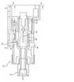
本発明は、図1および図2に示した気化装置10、および図3~図8に示した発熱素子に関するものである。気化装置10は、幅広い用途に使用することができ、下記に詳述するように、発熱素子に液体を吐出して、蒸気流を提供する。気化装置10は、一般的に、気化装置10によって生成された蒸気を吸引するためのマウスピース12を有する電子タバコ等の携帯用デバイスである。マウスピース12は、蒸気の流れを気化装置10から出すための導管14を含む。気化装置10の主な構成要素は、筐体16、取り外し可能なカートリッジカバー18、取り外し可能な流体供給カートリッジ20、流体供給カートリッジ20と関連する吐出ヘッド22、発熱素子24、および吐出ヘッド22から吐出された流体を気化するためのホルダー26を含む。気化装置10に関する他の構成要素は、充電式電源28、主回路基板30、および気化ドライバーカード32を含む。気化装置10の拡大部分を図2に示す。 The present invention relates to the
マウスピース12、および気化装置10の筐体16は、気化装置10によって吐出および気化される流体と適合性(compatible)があるという条件で、プラスチック、金属、ガラス、セラミック等の幅広い材料で作られる。特に適切な材料は、ポリ塩化ビニル、高密度ポリエチレン、ポリカーボネート、ステンレス鋼、サージカルスチール(surgical steel)、ニッケルめっき鋼等から選択される。マウスピース12や、流体および蒸気と接触する筐体16を含む全ての部品は、プラスチックで作られてもよい。導管14は、ステンレス鋼等の金属または気化装置10によって生成された熱および蒸気に対して耐性のある他の材料で作られてもよい。 The
図1に示すように、筐体16は、発熱素子24(下記に詳述する)および吐出ヘッド22に論理回路を提供する主回路基板30および気化ドライバーカード32を含んでもよい。充電式電源28は、筐体16内に収納されてもよい。別の実施形態において、取り外し可能な非充電式電池を筐体16内に収納してもよい。USB(Universal-Serial-Bus、図示せず)等の電気接続を使用して充電式電源28を再充電し、吐出ヘッド22および発熱素子24のプログラム設定を変更してもよい。微小流体吐出ヘッド22は、吐出ヘッド22によって吐出された流体を提供する流体供給カートリッジ20と流体連通する。 As shown in FIG. 1, the
吐出ヘッド22に背圧コントロールを提供するため、入口空気流制御装置を含んでもよい。入口空気流制御装置は、吐出ヘッド22に負圧がかかり過ぎないよう、ダンパースライド(damper slide)34と、発熱素子24および吐出ヘッド22に隣接する導管14に空気を出す空気導入孔36とを含んでもよい。 An inlet airflow control device may be included to provide back pressure control to the
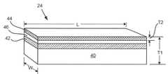
気化装置10の重要な構成要素は、図3に示した発熱素子24である。発熱素子24は、一般的に、高温固体セラミックベース(基板)40で作られ、その上に印刷された、または堆積した、あるいはセラミックベース40の中に埋め込まれた抵抗または導電層42を有する。抵抗または導電層42の材料は、銀および/またはカーボンスクリーン印刷された材料、タングステン、モリブデン、モリブデン-マンガン等を含む発熱素子に通常使用される幅広い材料から選択されるが、本発明はこれに限定されない。 An important component of the
上述したように、マウスピース12の導管14から蒸気のみが排出されるよう、吐出ヘッド22から吐出された実質的に全ての流体を気化させるのが望ましい。したがって、発熱素子24は、保護層46の上に形成された流体吸収または捕獲層44を含むのが望ましい。保護層46は、流体吸収または捕獲層44と抵抗または導電層42の間に配置され、セラミックベース40と同じ材料、または実質的に非多孔質の他の適切な高温材料で作られてもよい。保護層46の他の適切な材料は、アルミナ、窒化アルミニウム、シリカ、または窒化ケイ素を含むが、本発明はこれに限定されない。 As described above, it is desirable to vaporize substantially all the fluid discharged from the
発熱素子24の全体の厚さT1は、約4.0mm~約1.0cmまでの範囲であってもよい。言い換えると、1つの実施形態において、基板40、抵抗または導電層42、保護層46、および流体吸収または捕獲層44(すなわち、多孔層44、詳細は下記を参照)は、合わせて約4.0mm~約1.0cmの範囲の厚さを有する。流体吸収または捕獲層44の厚さT2は、約0.5mm~約3mm(例えば、約1mm~約2mm)の範囲であってもよい。抵抗または導電層42および保護層46の厚さは、本発明の実施形態では重要ではない。抵抗または導電層42が埋め込まれる場合、保護層46は必要としない。 The total thickness T1 of the
1つの実施形態において、図3に示すように、流体吸収または捕獲層44は、保護層46の上に堆積した少なくとも約50%の多孔率を有する多孔層である。別の実施形態において、流体吸収または捕獲層44の多孔率は、約60%~約85%の範囲であってよい。少なくとも約50%の多孔率とは、流体吸収または捕獲層44が多孔質であるか、または流体吸収または捕獲層44の全体の体積に対して少なくとも50%の空所(void space)体積を提供する凹みまたは空洞を有することを意味する。多孔率の範囲は、多孔層の実用限界である工学的判断に基づく。流体吸収または捕獲層44の質量をできるだけ小さくして、昇温速度を最適化し、流体吸収または捕獲層44を加熱する電力消費を最小化する。低質量は、95%の高多孔率を現実的な上限として選択する必要がある。95%以上の多孔率になると、構造が弱くなり過ぎて製造が困難になる。流体吸収または捕獲層44の最小多孔率として50%の多孔率が選択される。50%以下の多孔率になると、構造内の閉鎖された/隔絶された細孔により流体吸収または捕獲層44のウィッキング(wicking)特性が悪くなる。 In one embodiment, as shown in FIG. 3, the fluid absorption or
上述したように、幅W、長さL、および厚さTを有する矩形の発熱素子については、発熱素子24が式ESA>L×Wで定義される流体気化の実効表面積(ESA)を有するようにさらに定義される。円形の発熱素子については、発熱素子の実効表面積(ESA)がESA>II×R2で定義され、Rは、気化流体に露出される発熱素子の半径である。発熱素子24は、矩形または円形に限定されず、三角形、複雑形状等を含む任意の形状を使用してもよい。したがって、発熱素子24の実効表面積(ESA)は、保護層46の正規寸法よりも大きい。As described above, for a rectangular heating element having a width W, a length L, and a thickness T, the
別の実施形態において、図4に示すように、グリットブラスト加工されたセラミック層またはレーザーエッチングされたセラミック層48を使用して、吐出ヘッド22から吐出された流体を捕獲することができる。したがって、図のように、セラミック層48を保護層46に塗布してから、グリットブラスト加工またはレーザーエッチングを行って、セラミック層48に凹み(indentation)50を形成し、発熱素子24の実効表面積を大幅に増やすことができる。別の実施形態において、セラミック層48を追加してブラスト加工またはエッチングを行うのに対し、保護層46自体をグリットブラスト加工またはレーザーエッチングしてもよい。グリットブラスト加工またはレーザーエッチングされたセラミック層48または保護層46の表面は、多孔層44のように、その表面に液体のたまりを作るのを防ぐのに効果的であり、発熱素子24に吐出された流体のより迅速な気化を提供することができる。 In another embodiment, as shown in FIG. 4, a grit-blasted ceramic layer or a laser-etched
本発明の1つの実施形態に基づき、発熱素子24を作成する1つの方法を図5~図7において概略的に示す。発熱素子24は、92重量%~96重量%のアルミナセラミックベース40に埋め込まれたタングステン、モリブデン、またはモリブデン-マンガン等の高沸点の金属発熱材料(metal heating material)を含有し、導電層42を形成するセラミックベース40を含む。例えば、1つまたはそれ以上の上記金属の金属発熱抵抗スラリー(metal heating resistance slurry)をセラミックグリーン体のテープ成形に印刷してもよい。そして、複数層のセラミックグリーン体を4重量%~8重量%の焼結助剤を用いて高温で一体に積層して、セラミックベース40のアルミナセラミック発熱基板を形成する。セラミックベース40の材料は、窒化アルミナおよび立方窒化ホウ素を含むが、本発明はこれに限定されない。 Based on one embodiment of the present invention, one method for producing the
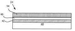
プロセスの次のステップにおいて、図6に示すように、導電層42に塗布された保護層46にガラスフリットの層54を塗布して、層54を提供する。ガラスフリットは、スクリーン印刷されたペーストまたはスラリーとして発熱素子24の表面に塗布することができる。 In the next step of the process, as shown in FIG. 6, the
プロセスの最後のステップにおいて、図7に示すように、ガラスフリットを発熱素子24に焼結して、約0.5mm~約3mm(例えば、約1mm~約2mm)の範囲の厚さを有する多孔表面56を提供する。吐出ヘッド22から発熱素子24に流体を吐出すると、流体は、焼結されたガラスフリット層に吸収され、流体含有多孔層58(図8)を形成する。流体含有多孔層58は、実効発熱素子表面面積の増加を提供するため、液体のより効果的な気化を行うことができる。 In the final step of the process, as shown in FIG. 7, the glass frit is sintered into the
10 気化装置
12 マウスピース
14 導管
16 筐体
18 カートリッジカバー
20 流体供給カートリッジ
22 吐出ヘッド/微小流体吐出ヘッド
24 発熱素子
26 ホルダー
28 充電式電源
30 主回路基板
32 気化ドライバーカード
34 ダンパースライド
36 空気導入孔
40 セラミックベース
42 導電層/抵抗または導電層
44 流体吸収または捕獲層/多孔層
46 保護層
48 セラミック層
50 凹み
54 層
56 多孔表面
58 流体含有多孔層
L 長さ
T1 全体の厚さ
T2 厚さ
W 幅10
Claims (8)
Translated fromJapanese前記発熱素子が、
基板の上に配置されるよう構成された導電層と、
前記導電層の上に配置されるよう構成された保護層と、
前記保護層の上に配置されるよう構成され、少なくとも50%の多孔率を有する多孔層と、を含み、
前記多孔層の前記保護層と反対側の主面には、前記多孔層を貫通しない複数の凹部が形成されており、
前記発熱素子が、前記発熱素子の大きさによって定義される平面表面面積よりも大きい、前記多孔層の前記主面における凹凸の表面積により規定される流体気化の実効表面積を有するよう構成された
発熱素子。A heat generating element used in a vaporizer,
The heat generating elementis
A conductive layer configured to be placed on top of the substrate,
A protective layer configured to be placed on the conductive layer,
Containing a porous layer configured to be placed on top of the protective layer and having a porosity of at least 50% .
A plurality of recesses that do not penetrate the porous layer are formed on the main surface of the porous layer opposite to the protective layer.
The heat generating element is configured to have an effective surface area for fluid vaporizationdefined by the surface area of the unevenness on the main surface of the porous layer, which is larger than the plane surface area defined by the size of the heat generating element. ..
式中、ESAが、前記実効表面積であり、
Lが、前記発熱素子の長さであり、
Wが、前記発熱素子の幅である
請求項1に記載の発熱素子。The heating element is configured to have a rectangular shape and has the effective surface area of fluid vaporization as defined by the formula ESA> L × W.
In the formula, ESA is the effective surface area.
L is the length of the heat generating element.
The heat generating element according to claim1 , wherein W is the width of the heat generating element.
請求項1または2に記載の発熱素子。The porous layer is0 . 5mm-3 . The heat generating element according to claim1 or2 , which has a thickness in the range of 0 mm.
請求項1~3のいずれか1項に記載の発熱素子。4. The substrate, the conductive layer, the protective layer, andthe porous layer are combined. 0 mmto 1 . The heat generating element according to any one of claims1 to3 , which has a thickness in the range of 0 cm.
請求項1~4のいずれか1項に記載の発熱素子。The heat generating element according to any one of claims1 to4 , wherein the porous layer hasa porosity in the range of 50%to 95%.
前記筐体に取り付けられたマウスピースと、
前記マウスピースに隣接して配置され、吐出ヘッドから吐出された流体を気化する請求項1~5のいずれか1項に記載の発熱素子と、を含む
気化装置。With the housing
The mouthpiece attached to the housing and
A vaporizer comprising the heat generating element according to any one of claims 1 to5 , which is arranged adjacent to the mouthpiece and vaporizes the fluid discharged from the discharge head.
前記吐出ヘッドを有するよう構成された気化装置および前記吐出ヘッドに隣接する発熱素子を提供することと、
前記発熱素子に前記流体を吐出することと、
流体の吐出中に前記発熱素子を起動することと、
前記発熱素子を使用して実質的に全ての前記流体を気化させることと、を含み、
前記発熱素子が、
基板の上に配置されるよう構成された導電層と、
前記導電層の上に配置されるよう構成された保護層と、
前記保護層の上に配置されるよう構成され、少なくとも50%の多孔率を有する多孔層と、を有し、
前記多孔層の前記保護層と反対側の主面には、前記多孔層を貫通しない複数の凹部が形成されており、
前記発熱素子が、前記発熱素子の大きさによって定義される平面表面面積よりも大きい、前記多孔層の前記主面における凹凸の表面積により規定される流体気化の実効表面積を有するよう構成された
方法。It is a method of vaporizing the fluid discharged from the discharge head.
To provide a vaporizer configured to have the discharge head and a heating element adjacent to the discharge head.
Discharging the fluid to the heat generating element and
Activating the heat generating element while discharging the fluid and
Including, using the heating element to vaporize substantially all of the fluid.
The heat generating elementis
A conductive layer configured to be placed on top of the substrate,
A protective layer configured to be placed on the conductive layer,
With a porous layer configured to be placed on top of the protective layer and having a porosity of at least 50% .
A plurality of recesses that do not penetrate the porous layer are formed on the main surface of the porous layer opposite to the protective layer.
A method configured such that the heating element has an effective surface area for fluid vaporization that is larger than the plane surface area defined by the size of the heating element and is defined by the surface areaof the irregularities on the main surface of the porous layer .
前記発熱素子が、矩形形状を有するよう構成され、式ESA>L×Wで定義される流体気化の前記実効表面積を有し、
式中、ESAが、前記発熱素子の前記実効表面積であり、
Lが、前記発熱素子の長さであり、
Wが、前記発熱素子の幅であり、
前記発熱素子が、前記流体に露出される
請求項7に記載の方法。Further comprising absorbing the fluid by the porous layer of the heating element.
The heatingelement isconfigured to have a rectangular shape and hasthe effective surface area of fluid vaporization as defined by the formula ESA> L × W.
In the formula, ESA is the effective surface area of the heat generating element.
L is the length of the heat generating element.
W is the width of the heat generating element.
The method according to claim7 ,wherein the heat generating element is exposed to the fluid.
Applications Claiming Priority (2)
| Application Number | Priority Date | Filing Date | Title |
|---|---|---|---|
| US15/369,961 | 2016-12-06 | ||
| US15/369,961US9993027B1 (en) | 2016-12-06 | 2016-12-06 | Heater element for a vaporization device |
Publications (2)
| Publication Number | Publication Date |
|---|---|
| JP2018088918A JP2018088918A (en) | 2018-06-14 |
| JP7009960B2true JP7009960B2 (en) | 2022-01-26 |
Family
ID=60582491
Family Applications (1)
| Application Number | Title | Priority Date | Filing Date |
|---|---|---|---|
| JP2017231725AActiveJP7009960B2 (en) | 2016-12-06 | 2017-12-01 | A method of vaporizing the fluid discharged by a heat generating element, a vaporizer, and a discharge head. |
Country Status (4)
| Country | Link |
|---|---|
| US (1) | US9993027B1 (en) |
| EP (1) | EP3332657B1 (en) |
| JP (1) | JP7009960B2 (en) |
| CN (2) | CN115778013A (en) |
Families Citing this family (18)
| Publication number | Priority date | Publication date | Assignee | Title |
|---|---|---|---|---|
| US10857311B2 (en) | 2010-01-12 | 2020-12-08 | Omega Life Science Ltd. | Method and apparatus for producing fine concentrated aerosol |
| IL251512B (en) | 2014-10-13 | 2022-06-01 | Omega Life Science Ltd | Mist sprayers |
| GB2561867B (en) | 2017-04-25 | 2021-04-07 | Nerudia Ltd | Aerosol delivery system |
| US10314342B2 (en)* | 2017-10-20 | 2019-06-11 | Altria Client Services Llc | E-vaping device using a jet dispensing cartridge, and method of operating the e-vaping device |
| WO2020019120A1 (en)* | 2018-07-23 | 2020-01-30 | 湖北中烟工业有限责任公司 | Ceramic heater and preparation method and use of ceramic heater |
| CN109222243A (en)* | 2018-09-27 | 2019-01-18 | 广东奥迪威传感科技股份有限公司 | A kind of electronic cigarette |
| MX2021009073A (en) | 2019-01-31 | 2021-09-10 | Dynavap Llc | INDIRECT EXOTHERMIC VAPORIZATION MATRIX. |
| CN110183225A (en)* | 2019-05-29 | 2019-08-30 | 肇庆市天华电子科技有限公司 | Electronic cigarette ceramic heating sheet and manufacturing method thereof |
| WO2020243822A1 (en) | 2019-06-05 | 2020-12-10 | Canopy Growth Corporation | Convection and conduction vaporizer and method for operating the same |
| US20220304383A1 (en)* | 2019-06-25 | 2022-09-29 | Philip Morris Products S.A. | An aerosol-generating system and a cartridge for an aerosol-generating system having improved heating assembly |
| CN112385901A (en)* | 2019-10-23 | 2021-02-23 | 湖北中烟工业有限责任公司 | Heating element and preparation method and application thereof |
| CN110953564A (en)* | 2019-11-15 | 2020-04-03 | 天津神菱燃气设备有限公司 | Vacuum electric wall-mounted boiler |
| CN111053298B (en)* | 2019-12-20 | 2022-03-15 | 深圳麦克韦尔科技有限公司 | Flexible heating element and manufacturing method thereof, flexible heating assembly and aerosol generator |
| CN111387555A (en) | 2020-02-27 | 2020-07-10 | 深圳麦克韦尔科技有限公司 | Electronic atomization device, atomization assembly, atomization element and manufacturing method thereof |
| EP4152985A1 (en)* | 2020-05-22 | 2023-03-29 | JT International SA | Layered heater assembly |
| CN114246369A (en)* | 2020-09-23 | 2022-03-29 | 深圳市合元科技有限公司 | Aerosol generating device and infrared heater |
| WO2023030962A1 (en)* | 2021-08-31 | 2023-03-09 | Jt International Sa | Liquid jet inhalation device |
| CN116941827A (en)* | 2022-04-20 | 2023-10-27 | 深圳麦克韦尔科技有限公司 | Electronic atomization device, atomizer, atomizing core and preparation method thereof |
Citations (4)
| Publication number | Priority date | Publication date | Assignee | Title |
|---|---|---|---|---|
| JP2005034021A (en) | 2003-07-17 | 2005-02-10 | Seiko Epson Corp | Electronic Cigarette |
| JP2012506263A (en) | 2008-10-23 | 2012-03-15 | ブッフベルガー,ヘルムート | Inhaler |
| WO2015066127A1 (en) | 2013-10-31 | 2015-05-07 | R. J. Reynolds Tobacco Company | Aerosol delivery device including a bubble jet head and related method |
| JP2015532828A (en) | 2012-09-04 | 2015-11-16 | アール・ジエイ・レイノルズ・タバコ・カンパニー | Electronic smoking article comprising one or more microheaters |
Family Cites Families (15)
| Publication number | Priority date | Publication date | Assignee | Title |
|---|---|---|---|---|
| DE69724559T2 (en)* | 1996-06-17 | 2004-07-15 | Japan Tobacco Inc. | FLAVORED ARTICLE |
| US6715859B2 (en) | 2001-06-06 | 2004-04-06 | Hewlett -Packard Development Company, L.P. | Thermal ink jet resistor passivation |
| US20090032034A1 (en) | 2002-11-26 | 2009-02-05 | Steinberg Dan A | Vaporization pipe with flame filter |
| US7195343B2 (en)* | 2004-08-27 | 2007-03-27 | Lexmark International, Inc. | Low ejection energy micro-fluid ejection heads |
| CN200944675Y (en)* | 2005-11-23 | 2007-09-05 | 费罗技术控股公司 | Heating element and liquid container using the same |
| US20130220314A1 (en) | 2012-02-29 | 2013-08-29 | General Electric Company | Medical vaporizer with porous vaporization element |
| GB2504076A (en) | 2012-07-16 | 2014-01-22 | Nicoventures Holdings Ltd | Electronic smoking device |
| US20140123989A1 (en)* | 2012-11-05 | 2014-05-08 | The Safe Cig, Llc | Device and method for vaporizing a fluid |
| WO2015031836A1 (en)* | 2013-08-29 | 2015-03-05 | Loec, Inc. | Electronic smoking device configured for automated assembly |
| US9872520B1 (en)* | 2014-06-26 | 2018-01-23 | Jeffrey Alan Elson | Vaporizer with means to power and recharge electrical devices |
| WO2016108694A1 (en)* | 2014-12-31 | 2016-07-07 | UTVG Global IP B.V. | Personal electronic delivery system, atomizer assembly, use thereof and corresponding production method |
| DE202015006397U1 (en)* | 2014-12-31 | 2015-12-07 | UTVG Global IP B.V. | Personal electronic delivery system |
| CN107846972B (en) | 2014-12-31 | 2020-09-15 | 尤特维吉环球爱普公司 | Personal electronic delivery system, atomizer assembly, use thereof and corresponding production method |
| MY197817A (en) | 2015-04-23 | 2023-07-18 | Altria Client Services Llc | Unitary heating element and heater assemblies, cartridges, and e-vapor devices including a unitary heating element |
| CN105725281A (en)* | 2016-05-04 | 2016-07-06 | 湖北中烟工业有限责任公司 | Compound functional atomizer and electronic cigarette containing same |
- 2016
- 2016-12-06USUS15/369,961patent/US9993027B1/enactiveActive
- 2017
- 2017-12-01JPJP2017231725Apatent/JP7009960B2/enactiveActive
- 2017-12-04CNCN202211661469.0Apatent/CN115778013A/enactivePending
- 2017-12-04CNCN201711258438.XApatent/CN108150989A/enactivePending
- 2017-12-05EPEP17205555.0Apatent/EP3332657B1/enactiveActive
Patent Citations (4)
| Publication number | Priority date | Publication date | Assignee | Title |
|---|---|---|---|---|
| JP2005034021A (en) | 2003-07-17 | 2005-02-10 | Seiko Epson Corp | Electronic Cigarette |
| JP2012506263A (en) | 2008-10-23 | 2012-03-15 | ブッフベルガー,ヘルムート | Inhaler |
| JP2015532828A (en) | 2012-09-04 | 2015-11-16 | アール・ジエイ・レイノルズ・タバコ・カンパニー | Electronic smoking article comprising one or more microheaters |
| WO2015066127A1 (en) | 2013-10-31 | 2015-05-07 | R. J. Reynolds Tobacco Company | Aerosol delivery device including a bubble jet head and related method |
Also Published As
| Publication number | Publication date |
|---|---|
| EP3332657A1 (en) | 2018-06-13 |
| US9993027B1 (en) | 2018-06-12 |
| JP2018088918A (en) | 2018-06-14 |
| CN115778013A (en) | 2023-03-14 |
| EP3332657B1 (en) | 2020-08-05 |
| US20180153215A1 (en) | 2018-06-07 |
| CN108150989A (en) | 2018-06-12 |
Similar Documents
| Publication | Publication Date | Title |
|---|---|---|
| JP7009960B2 (en) | A method of vaporizing the fluid discharged by a heat generating element, a vaporizer, and a discharge head. | |
| US9968136B1 (en) | Heater element for a vaporization device | |
| CN111163656B (en) | Reservoir for an inhaler, in particular for an electronic cigarette product | |
| CN113141678A (en) | Method for manufacturing heating element | |
| US9961940B2 (en) | Vaporizing assembly and vapor generating device | |
| CN109315024B (en) | Heater assembly for an aerosol-generating system | |
| ES2717539T3 (en) | Continuously heating unit for an aerosol generator system | |
| RU2673616C2 (en) | Unit of the evaporator | |
| CN111109665A (en) | Electronic atomization device and atomizer and heating body thereof | |
| CN107708453A (en) | Electron Aerosol Delivery System | |
| CN107708452A (en) | Electron Aerosol Delivery System | |
| KR20190021215A (en) | Cartridge for an e-belling device with an open microchannel | |
| CN117044999A (en) | Heating element, atomizer and electronic atomizing device | |
| EP3425998B1 (en) | Heater for a vaporization device, the vaporization device and method for vaporizing fluid thereof | |
| US10757759B2 (en) | Heater for a vaporization device | |
| CN220831954U (en) | Aerosol generating structure and electronic atomization device | |
| CN219422192U (en) | Mounting seat, atomizing core, atomizing device and atomizing equipment | |
| KR102874249B1 (en) | Method for manufacturing an electrically operable heating body for an inhaler | |
| CN118436128A (en) | Heating components, atomizing cores, atomizing devices and atomizing equipment | |
| KR20230153214A (en) | Ceramic atomizer | |
| KR20230155931A (en) | Ceramic atomizer for aerosol-generating device with different pore sizes | |
| WO2023102746A1 (en) | Atomization core, atomizer, and electronic atomization device | |
| KR20240110332A (en) | Ceramic atomizer for aerosol-generating device with different pore sizes and manufacturing method thereof | |
| CN118489960A (en) | Mounting seat, atomizing core, atomizing device and atomizing equipment | |
| HK40004656A (en) | Heater assembly for an aerosol-generating system |
Legal Events
| Date | Code | Title | Description |
|---|---|---|---|
| A621 | Written request for application examination | Free format text:JAPANESE INTERMEDIATE CODE: A621 Effective date:20200907 | |
| A131 | Notification of reasons for refusal | Free format text:JAPANESE INTERMEDIATE CODE: A131 Effective date:20210713 | |
| A521 | Request for written amendment filed | Free format text:JAPANESE INTERMEDIATE CODE: A523 Effective date:20210830 | |
| TRDD | Decision of grant or rejection written | ||
| A01 | Written decision to grant a patent or to grant a registration (utility model) | Free format text:JAPANESE INTERMEDIATE CODE: A01 Effective date:20211214 | |
| A61 | First payment of annual fees (during grant procedure) | Free format text:JAPANESE INTERMEDIATE CODE: A61 Effective date:20211227 | |
| R150 | Certificate of patent or registration of utility model | Ref document number:7009960 Country of ref document:JP Free format text:JAPANESE INTERMEDIATE CODE: R150 |