JP7009010B2 - Endpoint detection algorithm for atomic layer etching (ALE) - Google Patents
Endpoint detection algorithm for atomic layer etching (ALE)Download PDFInfo
- Publication number
- JP7009010B2 JP7009010B2JP2019512283AJP2019512283AJP7009010B2JP 7009010 B2JP7009010 B2JP 7009010B2JP 2019512283 AJP2019512283 AJP 2019512283AJP 2019512283 AJP2019512283 AJP 2019512283AJP 7009010 B2JP7009010 B2JP 7009010B2
- Authority
- JP
- Japan
- Prior art keywords
- oes
- processing
- data
- average
- determining
- Prior art date
- Legal status (The legal status is an assumption and is not a legal conclusion. Google has not performed a legal analysis and makes no representation as to the accuracy of the status listed.)
- Active
Links
Images


Classifications
- H—ELECTRICITY
- H01—ELECTRIC ELEMENTS
- H01J—ELECTRIC DISCHARGE TUBES OR DISCHARGE LAMPS
- H01J37/00—Discharge tubes with provision for introducing objects or material to be exposed to the discharge, e.g. for the purpose of examination or processing thereof
- H01J37/32—Gas-filled discharge tubes
- H01J37/32009—Arrangements for generation of plasma specially adapted for examination or treatment of objects, e.g. plasma sources
- H—ELECTRICITY
- H01—ELECTRIC ELEMENTS
- H01J—ELECTRIC DISCHARGE TUBES OR DISCHARGE LAMPS
- H01J37/00—Discharge tubes with provision for introducing objects or material to be exposed to the discharge, e.g. for the purpose of examination or processing thereof
- H01J37/32—Gas-filled discharge tubes
- H01J37/32917—Plasma diagnostics
- H01J37/32935—Monitoring and controlling tubes by information coming from the object and/or discharge
- H01J37/32963—End-point detection
- H—ELECTRICITY
- H01—ELECTRIC ELEMENTS
- H01J—ELECTRIC DISCHARGE TUBES OR DISCHARGE LAMPS
- H01J37/00—Discharge tubes with provision for introducing objects or material to be exposed to the discharge, e.g. for the purpose of examination or processing thereof
- H01J37/32—Gas-filled discharge tubes
- H01J37/32917—Plasma diagnostics
- H01J37/32935—Monitoring and controlling tubes by information coming from the object and/or discharge
- H01J37/32972—Spectral analysis
- H—ELECTRICITY
- H01—ELECTRIC ELEMENTS
- H01L—SEMICONDUCTOR DEVICES NOT COVERED BY CLASS H10
- H01L21/00—Processes or apparatus adapted for the manufacture or treatment of semiconductor or solid state devices or of parts thereof
- H01L21/02—Manufacture or treatment of semiconductor devices or of parts thereof
- H01L21/04—Manufacture or treatment of semiconductor devices or of parts thereof the devices having potential barriers, e.g. a PN junction, depletion layer or carrier concentration layer
- H01L21/18—Manufacture or treatment of semiconductor devices or of parts thereof the devices having potential barriers, e.g. a PN junction, depletion layer or carrier concentration layer the devices having semiconductor bodies comprising elements of Group IV of the Periodic Table or AIIIBV compounds with or without impurities, e.g. doping materials
- H01L21/30—Treatment of semiconductor bodies using processes or apparatus not provided for in groups H01L21/20 - H01L21/26
- H01L21/302—Treatment of semiconductor bodies using processes or apparatus not provided for in groups H01L21/20 - H01L21/26 to change their surface-physical characteristics or shape, e.g. etching, polishing, cutting
- H01L21/306—Chemical or electrical treatment, e.g. electrolytic etching
- H01L21/3065—Plasma etching; Reactive-ion etching
- H01L21/30655—Plasma etching; Reactive-ion etching comprising alternated and repeated etching and passivation steps, e.g. Bosch process
- H—ELECTRICITY
- H01—ELECTRIC ELEMENTS
- H01L—SEMICONDUCTOR DEVICES NOT COVERED BY CLASS H10
- H01L22/00—Testing or measuring during manufacture or treatment; Reliability measurements, i.e. testing of parts without further processing to modify the parts as such; Structural arrangements therefor
- H01L22/10—Measuring as part of the manufacturing process
- H01L22/12—Measuring as part of the manufacturing process for structural parameters, e.g. thickness, line width, refractive index, temperature, warp, bond strength, defects, optical inspection, electrical measurement of structural dimensions, metallurgic measurement of diffusions
- H—ELECTRICITY
- H01—ELECTRIC ELEMENTS
- H01J—ELECTRIC DISCHARGE TUBES OR DISCHARGE LAMPS
- H01J2237/00—Discharge tubes exposing object to beam, e.g. for analysis treatment, etching, imaging
- H01J2237/32—Processing objects by plasma generation
- H01J2237/33—Processing objects by plasma generation characterised by the type of processing
- H01J2237/334—Etching
- H—ELECTRICITY
- H01—ELECTRIC ELEMENTS
- H01L—SEMICONDUCTOR DEVICES NOT COVERED BY CLASS H10
- H01L22/00—Testing or measuring during manufacture or treatment; Reliability measurements, i.e. testing of parts without further processing to modify the parts as such; Structural arrangements therefor
- H01L22/20—Sequence of activities consisting of a plurality of measurements, corrections, marking or sorting steps
- H01L22/26—Acting in response to an ongoing measurement without interruption of processing, e.g. endpoint detection, in-situ thickness measurement
Landscapes
- Engineering & Computer Science (AREA)
- Physics & Mathematics (AREA)
- Plasma & Fusion (AREA)
- Chemical & Material Sciences (AREA)
- Analytical Chemistry (AREA)
- Manufacturing & Machinery (AREA)
- Computer Hardware Design (AREA)
- Microelectronics & Electronic Packaging (AREA)
- Power Engineering (AREA)
- General Physics & Mathematics (AREA)
- Condensed Matter Physics & Semiconductors (AREA)
- Spectroscopy & Molecular Physics (AREA)
- Drying Of Semiconductors (AREA)
- Plasma Technology (AREA)
- Polarising Elements (AREA)
- Investigating, Analyzing Materials By Fluorescence Or Luminescence (AREA)
Description
Translated fromJapanese原子層エッチング(ALE)は、層毎のエッチングを原子スケールの正確さで可能にするプラズマエッチング技術である。ALEは、たとえば、吸着反応と脱着反応との間で連続する複数ステップのサイクルを使用して薄い材料層を除去するための技術を実施する。ALEは、連続エッチングを代替するものであり、原子層の堆積に対する重要な同等物と見られている。 Atomic layer etching (ALE) is a plasma etching technique that enables layer-by-layer etching with atomic scale accuracy. ALE implements techniques for removing thin material layers using, for example, a continuous multi-step cycle between an adsorption reaction and a desorption reaction. ALE is an alternative to continuous etching and is seen as an important equivalent to atomic layer deposition.
エンドポイントの検出(EPD)は、エッチングされた材料が、下の層に対して取り除かれたことを検出することにより、プラズマエッチング処理を停止するか変更するために使用される。エッチングされた材料のタイプ、及び、エッチング処理のパラメータに応じて、エッチング処理のエンドポイントにおけるプラズマの光放射スペクトルの変化が発せられ、検出が比較的容易である場合があり、逆に、希薄で、検出が比較的困難である場合がある。たとえば、開いている比率が低い材料のエッチングは、光学発光分光法(OES)データの処理のための現在のアルゴリズムを使用した、エンドポイントの検出を困難にする場合がある。したがって、光学発光分光法(OES)データに基づくエッチングのエンドポイントの検出を、そのような困難なエッチング処理の条件においてより強固にすることに、向上が必要である。 Endpoint detection (EPD) is used to stop or change the plasma etching process by detecting that the etched material has been removed against the underlying layer. Depending on the type of material etched and the parameters of the etching process, changes in the light emission spectrum of the plasma at the etching process endpoint may occur, which may be relatively easy to detect, and conversely, dilute. , May be relatively difficult to detect. For example, etching low open ratio materials can make endpoint detection difficult using current algorithms for processing optical emission spectroscopy (OES) data. Therefore, improvements are needed to enhance the detection of etching endpoints based on optical emission spectroscopy (OES) data under such difficult etching conditions.
関連出願の相互参照
本出願は、2016年9月2日に出願された、「ENDPOINT DETECTION ALGORITHM FOR ATOMIC LAYER ETCHING」と題する、同時係属中の米国仮特許出願第62/382,904号に基づくとともに、優先権を主張する。この文献の内容は、その全体が、本明細書に組み込まれる。本出願は、2016年2月25日に出願され、「METHOD OF ENDPOINT DETECTION OF PLASMA ETCHING PROCESS USING MULTIVARIATE ANALYSIS」と題する、同時係属中の米国非仮特許出願第15/053,368号(参照番号TTI-240US2-CON)に関連する。この出願は、現在は米国特許第9,330,990号である、2013年10月17日に出願され、「METHOD OF ENDPOINT DETECTION OF PLASMA ETCHING PROCESS USING MULTIVARIATE ANALYSIS」と題する、同時係属中の米国非仮特許出願第14/056,059号(参照番号TTI-240)の継続出願である。この出願は、2012年10月17日に出願され、「METHOD OF ENDPOINT DETECTION OF PLASMA ETCHING PROCESS USING MULTIVARIATE ANALYSIS」と題する、米国仮特許出願第61/715,047号(参照番号TTI-240PROV)に基づくとともに、その優先権を主張する。この文献は、その全体が、参照することによって本明細書に組み込まれる。Cross-reference to related applications This application is based on the co-pending US Provisional Patent Application No. 62 / 382,904, entitled "ENDPOINT DESECTION ALGORTIHM FOR ATOMIC LAYER ETCHING", filed September 2, 2016. , Claim priority. The entire content of this document is incorporated herein by reference in its entirety. This application was filed on February 25, 2016 and is co-pending US Non-Provisional Patent Application No. 15 / 053,368, entitled "METHOD OF ENDPOINT EDITION OF PLASMA ETCHING PROCESS USING MULTIVARIATE ANALYSIS". -240US2-CON). This application is now U.S. Pat. No. 9,330,990, filed on October 17, 2013, entitled "METHOD OF ENDPOINT EDITION OF PLASMA ETCHING PROCESS USING MULTIVARIATE ANALYSIS". This is a continuation application of provisional patent application No. 14 / 056,059 (reference number TTI-240). This application was filed on October 17, 2012 and is based on US Provisional Patent Application No. 61 / 715,047 (reference number TTI-240) entitled "METHOD OF ENDPOINT EDITION OF PLASMA ETCHING PROCESS USING MULTIVARIATE ANALYSIS". At the same time, insist on its priority. This document is incorporated herein by reference in its entirety.
詳細な説明は、添付図面を参照して記載される。図中、参照符号のもっとも左の数字(複数可)は、その参照符号が最初に現れる図を示している。同じ数が、同様の特徴及び構成要素を参照するために、図面を通して使用される。 A detailed description will be given with reference to the accompanying drawings. In the figure, the leftmost number (s) of the reference code indicates the figure in which the reference code appears first. The same number is used throughout the drawing to refer to similar features and components.
本明細書に記載されるのは、複数処理のステップのプラズマエッチング処理システムにおける、処理ステップまたは処理ステップの組合せの、エンドポイントの検出のための構造、プラットフォーム、及び方法である。複数処理のステップの処理システムは、たとえば、原子層エッチング(ALE)処理であり、ALE処理は、プラズマエッチング処理システムからの、検出された、または得られた光学発光分光法(OES)データとしての、連続信号カーブによって示される場合がある。この実施例では、連続信号カーブ(すなわち、検出されたOESデータ)は、過渡信号(たとえば、処理ステップ間のスパイクまたはノイズ)を含む場合があり、したがって、連続信号カーブは、本明細書に記載のエンドポイントの検出を実施する前に、さらに同期、フィルタリング、及び平均化される場合がある。 Described herein are structures, platforms, and methods for endpoint detection of a process step or a combination of process steps in a multi-process step plasma etching system. The multi-step processing system is, for example, an atomic layer etching (ALE) processing, where the ALE processing is as detected or obtained optical emission spectroscopy (OES) data from a plasma etching processing system. , May be indicated by a continuous signal curve. In this embodiment, the continuous signal curve (ie, the detected OES data) may include transient signals (eg, spikes or noise between processing steps), and thus the continuous signal curve is described herein. Further synchronization, filtering, and averaging may occur before performing endpoint detection.
一実施態様では、同期され、フィルタリングされ、かつ平均化された連続信号カーブは、さらに、たとえば、複数処理のステップの吸着ステップ処理の平均を示す場合がある第1の不動部分、及び/または、たとえば、複数処理のステップの脱着ステップ処理の平均を示す場合がある、第2の不動部分を提供するように輪郭が描かれ、及び/または、識別される場合がある。この実施態様では、エンドポイント検出処理は、第1の不動部分のみ、第2の不動部分のみ、または、第1の不動部分と第2の不動部分との平均に基づく場合がある。他の実施態様では、過渡部/ノイズの値を無視できる場合、エンドポイント検出は、検出された連続信号カーブを直接利用する場合がある。すなわち、過渡信号を無視できる、検出された、同期された連続信号カーブまたはOESのデータである。 In one embodiment, the synchronized, filtered, and averaged continuous signal curves further include, for example, a first immovable portion that may represent the average of adsorption step processing of multiple processing steps, and / or. For example, it may be contoured and / or identified to provide a second immovable portion, which may indicate the average of the desorption step processes of the multi-process steps. In this embodiment, the endpoint detection process may be based on only the first immovable portion, only the second immovable portion, or the average of the first immovable portion and the second immovable portion. In another embodiment, endpoint detection may directly utilize the detected continuous signal curve if the transient / noise value is negligible. That is, the detected, synchronized continuous signal curve or OES data in which the transient signal is negligible.
本明細書に記載のように、第1の不動部分は、連続信号カーブまたはOESデータのフィルタリングされた上側エンベロープ(すなわち、吸着ステップ処理)の平均を示す場合がある。一方、第2の不動部分は、連続信号カーブまたはOESデータのフィルタリングされた下側エンベロープ(すなわち、脱着ステップ処理)の平均を示す場合がある。 As described herein, the first immobile portion may represent the average of the continuous signal curve or the filtered upper envelope (ie, adsorption step processing) of the OES data. The second immovable portion, on the other hand, may represent the average of the continuous signal curve or the filtered lower envelope (ie, desorption step processing) of the OES data.
フィルタリングされた上側エンベロープとフィルタリングされた下側エンベロープとは、OESデータの上側エンベロープと下側エンベロープとのそれぞれに現れ得る、過渡信号の除去を示している。 The filtered upper envelope and the filtered lower envelope indicate the elimination of transient signals that may appear in the upper and lower envelopes of the OES data, respectively.
一実施形態では、OESデータは、センサにより、エッチング処理ブロックから、特に、プラズマエッチング処理システムのプラズマ処理チャンバから検出及び取得される。センサによる検出及び取得は、プラズマ処理チャンバで、たとえば、ステップ処理(たとえば、吸着ステップ処理または脱着ステップ処理)の開始に関して同期され、及び/または、複数処理のステップの周期的な切替え(たとえば、吸着ステップ処理と脱着ステップ処理との間の切替え)と同期される。この実施例では、同期は、ハードウェア、ソフトウェア、またはハードウェアとソフトウェアとの両方の組合せによって実施される場合がある。 In one embodiment, the OES data is detected and acquired by the sensor from the etching processing block, particularly from the plasma processing chamber of the plasma etching processing system. Detection and acquisition by the sensor is synchronized in the plasma processing chamber, for example, with respect to the start of a step process (eg, adsorption step process or desorption step process), and / or periodic switching of multiple process steps (eg, adsorption). It is synchronized with (switching between step processing and desorption step processing). In this embodiment, synchronization may be performed by hardware, software, or a combination of hardware and software.
同期したOESデータにより、平滑化またはフィルタリング、平均化、及びエンドポイントの検出がその後に実施され得る。特に、過渡信号のフィルタリングは、たとえば、過渡信号が存在する、識別された期間(複数可)または信号の部分(複数可)を除くことによって実施され得る。過渡信号のフィルタリングの後に、移動平均フィルタなどのフィルタを使用することによって平均化を実施して、第1の不動部分、第2の不動部分、または第1の不動部分と第2の不動部分との両方の平均を生成する場合がある。 Synchronized OES data can be followed by smoothing or filtering, averaging, and endpoint detection. In particular, transient signal filtering can be performed, for example, by excluding the identified period (s) or portion of the signal (s) in which the transient signal is present. After filtering the transient signal, averaging is performed by using a filter such as a moving average filter to perform the first immovable part, the second immovable part, or the first immovable part and the second immovable part. May generate an average of both.
したがって、第1の不動部分、第2の不動部分、または第1の不動部分と第2の不動部分との両方の平均に基づき、エンドポイントの検出は、参照出願(すなわち、米国出願第61/715,047号、米国出願第14/056,059号、及び米国出願第15/053,368号)に記載のような統合アルゴリズムなどの主成分分析(PCA)を使用して、または、他の技術のPCAではない方法を使用することにより、判定される場合がある。 Therefore, endpoint detection is based on the average of both the first immovable part, the second immovable part, or the first immovable part and the second immovable part, and the endpoint detection is in reference application (ie, US application 61 / Using Principal Component Analysis (PCA), such as as described in 715,047, US Application 14/056,059, and US Application 15/053,368), or other. It may be determined by using a method that is not a technical PCA.
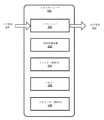
図1は、本明細書の実施形態に記載されるようなエッチング処理の間の、エンドポイントの検出の概観を示す例示的シナリオ100である。シナリオ100は、プラズマ処理システム、または、ALE処理などの、周期的に繰り返される複数ステップのプラズマ処理を利用する、任意の他のタイプのエッチングシステムである場合がある。 FIG. 1 is an
図示のように、OESモジュール102は、エッチング処理ブロック104に、有線または無線接続108を通して接続されている場合がある。エッチング処理ブロック104は、本明細書では、プラズマエッチングまたは、プラズマベースの処理である任意の他の処理を実施するブロック機構として簡略化されている。さらに、エッチング処理ブロック104は、たとえば、エッチング処理ブロック104において、エッチング処理の操作の間、OESデータ(または連続信号カーブ)を検出及び取得するセンサ106を含む場合がある。この実施例では、センサ106は、さらなる処理のために、取得したデータをOESモジュール102に送信する。 As shown, the
本明細書に記載のように、センサ106によるOESデータの取得は、エッチング処理ブロック104によって実施されるエッチング処理と同期される場合がある。その理由は、エンドポイントの検出が、処理ステップ(吸着ステップの処理など)が別の処理ステップ(脱着ステップの処理など)にシフトするか切り替わる、またはその逆の際の特定の時間または期間を認識しているためである。これに関し、エンドポイントの検出は、2つの方法で特定の時間または期間を認識することである。第1の方法は、ハードウェア構成要素を通してOESデータを直接受信することによるものであり、第2の方法は、過渡信号を確認し、過渡信号をフィルタリングし、以下にさらに論じるように、平均化された第1の不動部分と第2の不動部分とを提供するように構成されたソフトウェアを使用することによるものである。 As described herein, the acquisition of OES data by the sensor 106 may be synchronized with the etching process performed by the etching process block 104. The reason is that endpoint detection recognizes a specific time or time period when a processing step (such as the processing of a adsorption step) shifts or switches to another processing step (such as the processing of a desorption step) or vice versa. Because it is doing. In this regard, endpoint detection is the recognition of a particular time or period in two ways. The first method is by receiving OES data directly through the hardware components, the second method is to identify the transient signals, filter the transient signals and average them as discussed further below. This is due to the use of software configured to provide a first immovable portion and a second immovable portion.
図1を引き続き参照すると、OESモジュール102による処理には、たとえば、トランシーバ構成要素(図示せず)を通して取得されたOESデータを受信することと、受信されたOESデータを同期させることと、受信されたOESデータに存在し得る過渡信号のフィルタリングまたはカットオフと、周期的に繰り返される複数ステップのプラズマ処理における各処理ステップの平均の判定(たとえば、移動平均フィルタの使用)と、平滑化されたOESデータのエンドポイントを判定するためのアルゴリズム(たとえば、統合アルゴリズム)の適用と、が含まれる場合がある。この実施例では、OESモジュール102は、本発明の範囲を逸脱することなく、任意の適切なハードウェア、ソフトウェア、ファームウェア、またはこれらの組合せで実施され得る。さらに、OESモジュール102は、たとえば、エッチング処理ブロック104などの、プラズマ処理システムのプラズマ処理チャンバに直接結合されるか組み込まれている場合がある。 With reference to FIG. 1, the processing by the
エッチング処理ブロック104は、たとえば、ALE処理を含む、プラズマベースの処理システムを利用する場合がある。ALE処理は、周期的に繰り返される吸着ステップ(すなわち、連続信号カーブの上側エンベロープ)と、周期的に繰り返される脱着ステップ(すなわち、連続信号カーブの下側エンベロープ)にさらに輪郭が描かれる場合がある、複数ステップの処理(すなわち、連続信号カーブによって示される)を含む場合がある。この実施例では、エッチング処理ブロック104に接続されたセンサ106は、処理ブロック104によって実施されたプラズマ処理システムのプラズマ処理チャンバから、複数ステップの処理データ(すなわち、OESデータ)を検出及び取得する場合がある。OESデータが取得されると、センサ106は、取得されたOESデータをOESモジュール102に、有線または無線接続108を通して送信する場合がある。 The etching process block 104 may utilize a plasma-based processing system, including, for example, an ALE process. The ALE process may be further contoured in a periodically repeated adsorption step (ie, the upper envelope of the continuous signal curve) and a periodically repeated desorption step (ie, the lower envelope of the continuous signal curve). , May include multi-step processing (ie, indicated by a continuous signal curve). In this embodiment, the sensor 106 connected to the etching processing block 104 detects and acquires processing data (that is, OES data) of a plurality of steps from the plasma processing chamber of the plasma processing system implemented by the processing block 104. There is. When the OES data is acquired, the sensor 106 may transmit the acquired OES data to the
OESモジュール102は、センサ106を通して取得されたOESデータを受信するトランシーバ(図示せず)を含む場合がある。一実施態様では、OESモジュール102は、OESデータの取得における同期を促進するように構成されている場合がある。たとえば、センサ106は、エッチング処理ブロック104上の周期的な複数ステップのプラズマ処理の処理ステップの周期的な切替えに関し、OESデータのサンプリングの取得を同期させるために、エッチング処理ブロック104の操作と同期する。 The
さらに、OESモジュール102は、OESデータのプラズマステップ処理を同期させ、同期したOESデータ(または、ALE処理信号と呼ばれる場合がある)上の過渡信号のフィルタリングを促進し、フィルタリングされたOESデータの平均化を促進し、最後に、平滑化したALE処理信号またはOESデータのエンドポイントの判定を促進するように構成されている場合がある。 In addition, the
本明細書に記載のように、OESデータの同期、フィルタリングなどは、エンドポイントの分析または判定の前のデータの平滑化と呼ばれる場合がある。さらに、エンドポイントの検出には、相互参照する関連出願に記載の方法が利用される場合がある。特に、統合アルゴリズムが、複数ステップのプラズマ処理の各ステップ処理(すなわち、第1の不動部分または第2の不動部分)に基づくか、以下にさらに論じるように、複数ステップのプラズマ処理の少なくとも2つのステップ処理の平均(すなわち、第1の不動部分と第2の不動部分との平均)に基づいて、適用される場合がある。 As described herein, OES data synchronization, filtering, etc. may be referred to as data smoothing prior to endpoint analysis or determination. In addition, the methods described in cross-referenced related applications may be used to detect endpoints. In particular, the integrated algorithm is based on each step of the multi-step plasma process (ie, the first immovable portion or the second immovable portion), or at least two of the multi-step plasma processes, as further discussed below. It may be applied based on the average of the step processing (ie, the average of the first immovable part and the second immovable part).
さらに、OESモジュール102は、処理されたOESデータに基づいて制御パラメータを出力するように構成されている場合がある。出力された制御パラメータは、たとえば、エッチング処理ブロック104により、プラズマ処理システムの動作の間に、パラメータの調整のために、利用される場合がある。たとえば、センサ106によるOESデータのサンプリングの取得には、周期的な複数ステップのプラズマ処理の処理ステップの周期的な切替えに関する同期が必要である場合がある。換言すると、センサ106は、周期的な複数ステップのプラズマ処理の処理ステップの周期的な切替えに関するOESデータの取得の調整のために、出力制御パラメータを受信する場合がある。 Further, the
OESデータの取得において、センサ106は、たとえば、エッチング処理ブロック104におけるプラズマ処理システムのスペクトル(すなわち、OESデータ)を測定する分光計を含む場合がある。スペクトルは、この実施例では、波長または周波数の関数としての光の強度を含む場合がある。センサ106は、他の光検出器がプラズマ処理システムのプラズマ処理チャンバにおける光の強度を測定するために利用される場合があることから、分光計には限定されない場合がある。 In acquiring OES data, the sensor 106 may include, for example, a spectrometer that measures the spectrum (ie, OES data) of the plasma processing system in the etching processing block 104. The spectrum may include, in this example, the intensity of light as a function of wavelength or frequency. The sensor 106 may not be limited to a spectrometer, as other photodetectors may be used to measure the intensity of light in the plasma processing chamber of the plasma processing system.
本明細書に記載の実施形態が、同期され、フィルタリングされるなどするデータのソースとしてプラズマ処理システムを参照しているが、他のエッチング処理システムが、エッチング処理ブロック104において利用され得、また、本明細書に記載のものと同じ処理が、エンドポイントの判定の前に、信号をより強固にするために適用される場合がある。 Although the embodiments described herein refer to a plasma processing system as a source of data to be synchronized, filtered, etc., other etching processing systems may be utilized in the etching processing block 104 as well. The same processing as described herein may be applied to make the signal stronger prior to endpoint determination.
図2は、本明細書の本実施態様に記載されるようなOESモジュール102の例示的な概略ブロック図である。図示のように、OESモジュール102は、トランシーバ200と、信号同期装置202と、フィルタ204と、メモリ206と、プロセッサ208とを含む場合がある。OESモジュール102は、入力信号210及び出力信号212をさらに示している。OESモジュール102は、信号同期装置202、フィルタ204、及びメモリ206などのハードウェア構成要素によって実施されているものであるが、プロセッサ208は、これらハードウェア構成要素の機能を実行するソフトウェアアルゴリズムを実施するように構成されている場合がある。 FIG. 2 is an exemplary schematic block diagram of the
たとえば、ソフトウェアアルゴリズムは、センサ106による信号の検出及び取得(すなわち、連続信号カーブまたはOESデータの取得)の同期、及び、OESデータの複数処理のステップ(たとえば、吸着のステップ処理及び脱着のステップ処理)の同期を実施する場合がある。さらに、ソフトウェアアルゴリズムは、OESデータの過渡信号の検出、識別、及びフィルタリングと、フィルタリングされたOESデータの第1の不動部分(たとえば、吸着ステップ処理)を生成するための、フィルタリングされたOESデータの判定及び平均化と、フィルタリングされたOESデータの第2の不動部分(たとえば、脱着ステップ処理)を生成するための、フィルタリングされたデータの判定及び平均化とを実施する場合がある。 For example, the software algorithm may synchronize the detection and acquisition of a signal by the sensor 106 (ie, acquisition of a continuous signal curve or OES data), and multiple processing steps of OES data (eg, adsorption step processing and desorption step processing). ) May be performed. In addition, the software algorithm detects, identifies, and filters transient signals in the OES data and in the filtered OES data to generate a first immovable portion of the filtered OES data (eg, adsorption step processing). Determination and averaging may be performed and determination and averaging of the filtered data to generate a second immovable portion of the filtered OES data (eg, desorption step processing).
さらにまた、ソフトウェアアルゴリズムは、吸着ステップ処理(すなわち、第1の不動部分)の平均に基づくか、脱着ステップ処理(すなわち、第2の不動部分)の平均に基づくか、吸着ステップ処理の平均と脱着ステップ処理の平均との組合せの平均(すなわち、第1の不動部分と第2の不動部分との組合せの平均)に基づくエンドポイントの検出を実施する場合がある。さらに、ソフトウェアアルゴリズムは、過渡信号が存在しない(すなわち、無視できる過渡信号)場合では、検出された連続信号カーブまたはOESデータの原データの平均に基づくエンドポイントの検出を実施する場合がある。原データの平均は、この実施態様では、取得されたOESデータに存在する、無視できる過渡信号を除外しないか、フィルタリングしないことを示している。 Furthermore, the software algorithm is based on the average of the adsorption step process (ie, the first immovable portion) or the desorption step process (ie, the second immovable part), or the average of the adsorption step process and the desorption. Endpoint detection may be performed based on the average of the combination with the average of the step processing (ie, the average of the combination of the first immovable part and the second immovable part). In addition, software algorithms may perform endpoint detection based on the average of the detected continuous signal curves or the original data of the OES data in the absence of transient signals (ie, negligible transient signals). The averaging of the source data indicates that in this embodiment, the acquired OES data does not exclude or filter the negligible transient signals present.
図2を引き続き参照すると、トランシーバ200は、センサ106から、連続信号カーブまたはOESデータ(プラズマ処理システムの間)などの入力信号210を受信する、回路、ソフトウェア、またはそれらの組合せを含む場合がある。トランシーバ200による受信及び送信は、特定の予め規定された時間内に実施され得るか、構成される場合があるように、継続的方式で実施され得る。トランシーバ200は、センサ106によるOESデータの同期及び制御信号の取得のため、ならびに、プラズマ処理条件の切替えの方式またはタイミングなど、エッチング処理ブロック104のさらなる同期及び制御操作のために、出力信号212(たとえば、出力制御パラメータ)を送信するようにさらに構成されている場合がある。たとえば、センサ106によるOESデータの検出及び取得は、エッチング処理ブロック104によって周期的に繰り返される少なくとも2つの処理ステップと同期される。この実施例では、出力信号212は、必要な制御パラメータに、センサ106及びエッチング処理ブロック104の動作を同期させることを促進する場合がある。 With reference to FIG. 2, the
前述の実施例のハードウェア構成要素の代替形態として、ソフトウェアアルゴリズムが、OESデータの同期を実施する場合がある。たとえば、プロセッサ208は、吸着ステップ処理、脱着ステップ処理、過渡信号部分、及び、OESデータ上の条件の他の変更を示す場合がある、連続信号カーブの部分を識別するソフトウェアアルゴリズムを実施する場合がある。 As an alternative to the hardware components of the embodiments described above, software algorithms may perform OES data synchronization. For example,
一実施態様では、同期され、フィルタリングされ、かつ、平均化されることになる入力信号210は、エンドポイントの検出のための様々な態様を提供する場合がある。たとえば、これらの態様は、吸着ステップのみ(すなわち、第1の不動部分)の平均、脱着ステップのみ(すなわち、第2の時間に依存する光信号の部分)の平均、特定の時間内の吸着ステップと脱着ステップとの組合せ、第1の時間内の吸着ステップと第2の異なる時間内の脱着ステップとの組合せ、及び、他の異なる組合せを含んでいる。この実施例では、ソフトウェアアルゴリズムは、入力信号210の特定の態様に基づくエンドポイントの検出を実施する場合がある。さらに、各態様に関するエンドポイントの検出は、エンドポイントの検出の目的のための処理のために、信号210の可能性のあるベストな態様を得るために、比較される場合がある。 In one embodiment, the
たとえば、OESモジュール102は、第1の不動部分(すなわち、吸着ステップ処理)に基づくプラズマ処理システムのエンドポイントを判定するように構成されている。この実施例では、センサ106は、OESデータ、特に、周期的に繰り返される吸着ステップ処理上のOESデータを取得するように構成される場合がある。すなわち、センサ106は、サイクルタイムの増大または減少、時間内の過渡信号、プラズマ塩素処理における反応のための吸着の速度定数の増大、作動温度などを検出するように構成されている場合がある。これらパラメータ(すなわち、作動温度、サイクル時間の増大または減少など)は、吸着強度信号によって示される場合があり、エンドポイントの判定のために、信号同期装置202、フィルタ(複数可)204、及びプロセッサ208によるさらなる処理のために、トランシーバ200による入力信号210として受信される場合がある。 For example, the
別の実施例では、OESモジュール102は、時間に基づく吸着及び脱着のステップの信号の組合せなど、周期的に繰り返される複数ステップ処理の組合せに基づくプラズマ処理システムのエンドポイントを判定するように構成されている。この実施例では、センサ106は、周期的に繰り返される吸着及び脱着のステップ処理に関するOESデータを取得するように構成されている場合がある。すなわち、センサ106は、周期的な吸着及び脱着のステップ処理のそれぞれのサイクルタイムの増大または減少、周期的に繰り返される複数ステップのプラズマ処理の処理ステップ内の切替えに関連する、プラズマ処理ガス及び他のプラズマ処理条件の切替えに起因する時間内の過渡信号、プラズマ塩素処理の反応、温度に関する吸着及び/または脱着の速度定数の増大などを検出するように構成されている場合がある。 In another embodiment, the
前述の実施例では、検出されたパラメータ(すなわち、温度、サイクルタイムの増大または減少など)は、単一の連続信号カーブまたはOESデータによって示される場合がある。一実施形態では、ハードウェア構成要素(すなわち、信号同期装置、フィルタなど)、またはソフトウェアアルゴリズム、またはそれらの組合せは、単一の連続信号カーブまたはOESデータの、吸着ステップ処理(すなわち、第1の不動部分)の平均と、脱着ステップ処理(すなわち、第2の不動部分)の平均との輪郭を描くとともに計算する場合がある。 In the above embodiments, the detected parameters (ie, temperature, increase or decrease in cycle time, etc.) may be indicated by a single continuous signal curve or OES data. In one embodiment, a hardware component (ie, a signal synchronizer, a filter, etc.), or a software algorithm, or a combination thereof, is a single continuous signal curve or OES data adsorption step process (ie, first). The average of the immovable part) and the average of the desorption step processing (that is, the second immovable part) may be drawn and calculated.
本明細書に記載するように、信号同期装置202は、出力信号212をエッチング処理ブロック104及び/またはセンサ106に送信することにより、同期を実施するように構成されている場合がある。たとえば、少なくとも2つの周期的に繰り返される処理ステップの同期には、それらのそれぞれのサイクルタイムの調整、それらのそれぞれのサンプリング周期のインターバルの調整、作動温度、プラズマ塩素処理の反応に関する吸着及び/または脱着の速度定数の増大または減少などが含まれる場合がある。本実施例では、同期により、フィルタ204による処理の前に、入力信号210を同調または同期させるように、特定の基準ポイントまたはシークエンスが確立される場合がある。 As described herein, the
別の実施例では、信号同期装置202は、周期的な複数ステップのプラズマ処理の処理ステップの周期的な切替え(すなわち、吸着ステップ処理から脱着ステップ処理へ、またはその逆)に関する正確なタイミングで、OES信号のサンプリングを生じさせるために、OESデータの同期した取得と、プラズマ処理条件の切替えとを促進する場合がある。 In another embodiment, the
入力信号210のエラーに起因して、信号同期装置202が、少なくとも2つの周期的に繰り返される処理ステップの同期を実施できないかもしれない場合、プロセッサ208は、必要な出力信号のパラメータをセンサ106に送信することにより、入力信号210内のエラーの収集を促進するように構成されている場合がある。 If the
単一の周期的に繰り返されるステップ処理(すなわち、吸着ステップ処理または脱着ステップ処理)に関し、信号の同期が実施されない(すなわち、バイパスされる)場合があり、単一の周期的に繰り返されるステップ処理(すなわち、入力信号210)は、エンドポイントの検出の前に、過渡信号のフィルタリングを経る場合がある。このエンドポイントの検出は、統合アルゴリズムまたは主成分分析(PCA)、または、任意の他のタイプのPCAではない方法の適用を通して実施される。 For a single cyclically repeated step process (ie, adsorption step process or desorption step process), signal synchronization may not be performed (ie, bypassed) and a single cyclically repeated step process. (Ie, the input signal 210) may go through transient signal filtering prior to endpoint detection. Detection of this endpoint is performed through the application of an integrated algorithm or principal component analysis (PCA), or any other type of non-PCA method.
本明細書に記載のように、相互参照する関連出願の統合アルゴリズムは、単一の周期的に繰り返される処理の個別のエンドポイントの判定に関して採用されている。さらに、統合アルゴリズムも、受信したOESデータの複数ステップ処理に関するエンドポイントの判定のために利用され得る。 As described herein, the cross-referenced related application integration algorithm has been adopted for determining the individual endpoints of a single cyclically repeated process. In addition, integration algorithms can also be used to determine endpoints for multi-step processing of received OES data.
同期された少なくとも2つの周期的に繰り返される処理ステップの、信号同期装置202の出力からの取得の後に、フィルタ(複数可)204は、吸着ステップ処理から脱着ステップ処理へ、及びその逆のプラズマシステムの周期的な切替えの間に生じる場合がある過渡信号を、カットオフするように構成されている場合がある。 After acquisition of at least two synchronously cyclically repeated processing steps from the output of the
たとえば、過渡信号は、受信されたOESデータのスペクトル内の、各サンプリングインターバルの開始時か、すべての時間の後に、生じるように検出される場合がある。別の実施例では、過渡信号は、吸着または脱着の強い光信号が、所定の閾値より上である場合に検出される場合がある。これら実施例では、フィルタ204は、各サンプリングインターバルの開始時、または、所定の閾値を使用する場合、検出された過渡信号が閾値を超えた場合に、過渡信号を除去するように構成されている場合がある。閾値は、この場合、過渡信号の存在を規定する。 For example, transient signals may be detected within the spectrum of received OES data to occur at the beginning of each sampling interval or after all times. In another embodiment, the transient signal may be detected when the strong adsorption or desorption optical signal is above a predetermined threshold. In these embodiments, the
過渡信号の除去または最小化により、フィルタリングされた吸着の強い光信号が、以下にさらに論じるような別のフィルタリング処理をさらに経る場合がある。同様に、脱着の強い光信号に関し、前の記載で論じたものと同じ手順(たとえば、閾値の使用)が、脱着の強い光信号から過渡信号をカットオフするために適用される場合がある。 Due to the elimination or minimization of transient signals, the filtered strong optical signal of adsorption may undergo additional filtering processes as further discussed below. Similarly, for strongly desorbed optical signals, the same procedures as discussed above (eg, the use of thresholds) may be applied to cut off transient signals from strongly desorbed optical signals.
吸着及び/または脱着の強い光信号からの過渡信号の除去の後に、フィルタ204は、別のアルゴリズムを実施するか、フィルタリングされたOESデータを平均化するように、フィルタ反応機能(たとえば、移動平均フィルタ)を適用するように構成されている場合がある。移動平均フィルタは、この場合、各データポイントを、特定のスパン内で規定された隣接するデータポイントの平均と置き換えることによってデータを平滑化する場合がある。さらに、移動平均フィルタは、以下に図3でさらに論じるように、第1の不動部分、第2の不動部分、または第1の不動部分と第2の不動部分との平均を生成する場合がある。 After removal of transient signals from strongly adsorbed and / or desorbed optical signals,
吸着及び/または脱着の強い光信号の平滑化及び平均化の後に、エンドポイントが、統合アルゴリズムによって検出される。相互参照した関連出願におけるエンドポイントの判定は、適用可能であり得るように、本明細書に採用される。 After smoothing and averaging of strongly adsorbed and / or desorbed optical signals, endpoints are detected by an integrated algorithm. The endpoint determination in the cross-referenced related application is adopted herein as may be applicable.
1つまたは複数のプロセッサ208は、単一の処理ユニットコントローラであるか、複数の処理ユニットコントローラである場合があり、それらのすべてが、単一もしくは複数の計算ユニットまたは複数のコアを含む場合がある。プロセッサ(複数可)208は、動作命令に基づき、周期的な複数ステップ処理信号を操作する場合がある、1つまたは複数のマイクロプロセッサ、マイクロコンピュータ、マイクロコントローラ、デジタル信号プロセッサ、中央処理ユニット、ステートマシン、論理回路、及び/または任意のデバイスとして実施される場合がある。他の能力の内、プロセッサ(複数可)208は、メモリ206または他のコンピュータ可読記録媒体に貯蔵された、コンピュータ可読命令またはプロセッサアクセス可能命令をフェッチ及び実行するように構成されている場合がある。たとえば、プロセッサ(複数可)208は、吸着ステップ処理、脱着ステップ処理、またはこれら両方の組合せか平均に基づくエンドポイントの判定を判定するように構成されている場合がある。 One or
メモリ206は、本明細書に記載の様々な機能を実施するように、プロセッサ(複数可)208によって実行される命令を貯蔵するための、非制定法のコンピュータ可読記録媒体の実施例である。たとえば、メモリ206は、概して、揮発性メモリと不揮発性メモリ(たとえば、RAM、ROMなど)との両方を含む場合がある。メモリ206は、本明細書では、メモリまたはコンピュータ可読記録媒体と称される場合がある。メモリ206は、本明細書の実施態様に記載の動作及び機能を実行するために構成された特定のマシンのように、プロセッサ(複数可)208によって実行され得る、コンピュータ可読命令、プロセッサ実行可能プログラム指示をコンピュータプログラムコードとして貯蔵することが可能である。
メモリ206は、本明細書に記載のエンドポイントの判定のための1つまたは複数のアプリケーション(図示せず)をさらに貯蔵する場合がある。このアプリケーションは、予め構成され/インストールされ、かつ、ダウンロード可能なアプリケーションを含む場合がある。さらに、メモリ206は、本明細書に記載のように、エンドポイントの判定のための処理を経るOESデータを貯蔵する場合がある。たとえば、メモリ206は、信号同期装置202、フィルタ(複数可)204などの出力を貯蔵する。 The
図3は、本明細書に記載のOESモジュールによって収集及び処理されたOESデータ300の例示的なグラフ表示である。OESデータ300は、時間またはサイクルにわたって光強度の量が異なる単一の連続信号カーブ302を含む場合がある。光強度の量は、垂直な「Y」軸により、時間にわたって示されている。この時間は、水平な「X」軸によって示される場合がある。さらに、単一の連続信号カーブ302の上側エンベロープと下側エンベロープとは、吸着ステップ処理と脱着ステップ処理とのそれぞれなど、周期的な複数ステップ処理を示す場合がある。 FIG. 3 is an exemplary graphical representation of the
単一の連続信号カーブ302は、さらに、上側エンベロープに存在する場合がある、過渡信号304-2、304-4、…、304-nを含み、これにより、単一の連続信号カーブ302の吸着ステップ処理が示される。同様に、過渡信号306-2、306-4、…、306-nが下側エンベロープに存在する場合があり、これにより、単一の連続信号カーブ302の脱着ステップ処理が示される。これら過渡信号304及び306は、複数ステップのプラズマ処理の周期的な切替えの間、または、サイクルの特定の持続時間にわたって周期的に生じる場合がある、ノイズ、スパイク、または不要な信号を示す場合がある。 The single
一実施形態では、フィルタ204は、フィルタ204による平均化(たとえば、移動平均フィルタの適用)の前に、単一の連続信号カーブ302を平滑化するように、過渡信号304及び306をカットオフするか除去するように構成されている場合がある。たとえば、プロセッサ208は、周期的な切替えステップ処理の各々の始点からの特定の時間の間に生じる過渡信号304及び306を検出する場合がある。この実施例では、フィルタ204は、サイクルの特定の時間内にある単一の連続信号カーブ302の一部をカットオフする場合がある。別の実施例では、プロセッサ208は、所定の閾値を使用して、過渡信号304及び306の存在を検出する場合がある。この他の実施例では、フィルタ204は、過渡信号の存在を示す、所定の閾値の上の単一の連続信号カーブ302の一部をカットオフする場合がある。 In one embodiment, the
過渡信号304及び306の除去の後に、フィルタ204は、たとえば、移動平均フィルタを適用して、単一の連続信号カーブ302の残りの上側エンベロープ及び残りの下側エンベロープの平均を計算する場合がある。図3に示すように、吸着ステップ処理を示す残りの上側エンベロープの平均は、第1の不動部分308の称される場合があり、一方、脱着ステップ処理を示す残りの下側エンベロープの平均は、第2の不動部分310と称される場合がある。 After removal of the
一実施形態では、第1の不動部分308は、過渡信号304を除去した後の、吸着ステップ処理の信号部分の平均を含んでいる。同様に、第2の不動部分310は、過渡信号306を除去した後の、脱着ステップ処理の信号部分の平均を含んでいる。さらに、図3は、第1の不動部分308と第2の不動部分310との組合せの、計算された平均を示す場合がある平均信号312を示している。 In one embodiment, the first
別の実施態様では、過渡信号304及び306の値が無視できる場合、第1の不動部分308及び第2の不動部分310は、過渡信号304及び306をフィルタリングする必要なく、直接計算される場合がある。この他の実施態様では、平均信号312は、受信した単一の連続信号カーブ302に直接基づく場合がある。 In another embodiment, if the values of the
上述の図2のOESモジュール102を参照すると、OESモジュール102は、第1の不動部分308、第2の不動部分310、及び/または平均信号312に基づくエンドポイントの検出を実施する場合がある。エンドポイントの検出を参照すると、相互参照した関連出願の統合アルゴリズムは、OESデータ300のエンドポイントを判定するために利用される場合がある。 With reference to the
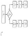
図4は、プラズマエッチング処理システムにおける周期的に繰り返される複数処理のステップのエンドポイントの検出のための例示的処理400を示している。本方法が記載される順番は、限定として解釈されることは意図しておらず、任意の数の記載の方法のブロックを、本方法、または代替的方法を実施する任意の順番で組み合わせることができる。さらに、個別のブロックは、本明細書に記載の主題の精神及び範囲から逸脱することなく、本方法から除去される場合がある。さらに、本方法は、本発明の範囲を逸脱することなく、任意の適切なハードウェア、ソフトウェア、ファームウェア、またはこれらの組合せで実施され得る。 FIG. 4 shows an
ブロック402では、データの検出及び取得が実施される。たとえば、プラズマ処理システムに関し、光検出デバイス(すなわち、センサ106)が、光学発光分光法(OES)データ(たとえば、OESデータ300)を、1つまたは複数のエッチング処理の実行のセットから取得するために利用される場合がある。相互参照した出願にさらに論じるように、スペクトルは、プラズマエッチング処理の実行のエッチングの各々の間に、n回取得される場合がある。ここで、nは2以上の整数である。連続したOESデータの取得(すなわち、スペクトルの取得)間のサンプリングインターバルは、0.01秒から1.0秒に変化する場合がある。取得されたOESデータのセットの各々、すなわち、スペクトルは、CCD(電荷結合デバイス)光検出デバイスのmピクセルに対応する、mの測定された光強度を含む場合があり、mピクセルの各ピクセルは、センサ106において光散乱デバイスとして通常は採用される回折格子によってピクセル上に投影された特定の光の波長に対応する。 At
前述の実施例では、取得されたOESデータ300は、トランシーバ200を通してOESモジュール102によって受信される場合がある。 In the above embodiment, the acquired
ブロック404では、OESが複数ステップ処理を含むかを判定する。 At
ブロック404における条件が、単一ステップ処理、すなわち、吸着ステップ処理のみか、脱着ステップ処理のみである場合、ブロック406の「NO」の分枝を辿り、吸着ステップ処理または脱着ステップ処理の過渡信号の除去が、たとえば、ブロック408における移動平均フィルタの適用の前に、適用される場合がある。ブロック408における信号の平均化により、第1の不動部分308、第2の不動部分310、及び/または、組み合わせられた第1の不動部分と第2の不動部分との平均である、平均信号312が生成される。 When the condition in the
ブロック410では、エンドポイントの検出が実施される。たとえば、エンドポイントの判定は、第1の不動部分308、第2の不動部分310、及び/または、平均信号312に基づく場合がある。 At
ブロック404における条件が、複数ステップ処理である場合、ブロック412の「YES」の分枝を辿り、受信したOESデータ(たとえば、OESデータ300)の同期が、信号同期装置202によって実施され得る。 When the condition in the
ブロック414では、過渡信号の除去が実施される。たとえば、フィルタ204は、単一の連続信号カーブ302の検出された過渡信号304及び306をカットオフする。 At
ブロック414では、複数ステップ処理のエンドポイントの検出が実施される。たとえば、相互参照した出願に記載されるような統合アルゴリズムが、エンドポイントを検出するために利用される場合がある。別の実施例では、他の従来技術のエンドポイントの検出も利用される場合がある。これら実施例では、エンドポイントの検出は、第1の不動部分308、第2の不動部分310、及び/または、組み合わせられた第1の不動部分と第2の不動部分との平均である、平均信号312に基づいている。 At
本発明に係る実現は、特定の実施形態の文脈において記載されてきた。これら実施形態は、限定ではなく、説明的ものであることを意味している。多くの変形形態、変更形態、追加形態、及び向上形態が可能である。したがって、複数の例が、単一の例として、本明細書に記載の構成要素に関して提供される場合がある。様々な構成要素、操作、及びデータの貯蔵の間の境界は、いくぶん自由裁量によるものであり、特定の操作は、特定の説明的構成の文脈で説明される。機能の他の割当てが予見され、また、添付の特許請求の範囲の範囲内となり得る。最後に、様々な構成において別々の構成要素として提供された構造及び機能は、組み合わせられた構造または構成要素として実施される場合がある。これら及び他の変形形態、変更形態、追加形態、及び向上形態は、添付の特許請求の範囲に規定されるような本発明の範囲内にあり得る。 The realization of the present invention has been described in the context of a particular embodiment. These embodiments are meant to be descriptive, not limiting. Many variants, modifications, additions, and improvements are possible. Accordingly, a plurality of examples may be provided as a single example with respect to the components described herein. The boundaries between the various components, operations, and storage of data are somewhat discretionary, and certain operations are described in the context of certain descriptive constructs. Other allocations of functionality are foreseen and may be within the scope of the appended claims. Finally, the structures and functions provided as separate components in various configurations may be implemented as combined structures or components. These and other variants, modifications, additions, and improvements may be within the scope of the invention as set forth in the appended claims.
図5は、本明細書に記載のプラズマエッチング処理システムにおける周期的に繰り返される複数処理のステップのエンドポイントの検出のための例示的処理500を示している。以下の例示的なエンドポイントの検出は、相互参照した出願に基づくものであり、それとして、読み手は、ブロック502からブロック514のさらなる議論及び説明に関し、相互参照した出願を見ることができる。さらに、エンドポイントの検出は、第1の不動部分308、第2の不動部分310、または、第1の不動部分と第2の不動部分との平均(すなわち、平均信号312)に適用される場合がある。さらにまた、当該技術の任意の他の方法が、本明細書に記載のように、エンドポイントを検出するために適用される場合がある。本方法が記載される順番は、限定として解釈されることは意図しておらず、任意の数の記載の方法のブロックを、本方法、または代替的方法を実施するための任意の順番で組み合わせることができる。さらに、個別のブロックは、本明細書に記載の主題の精神及び範囲から逸脱することなく、本方法から除去される場合がある。さらに、本方法は、本発明の範囲を逸脱することなく、任意の適切なハードウェア、ソフトウェア、ファームウェア、またはこれらの組合せで実施され得る。 FIG. 5 shows an
ブロック502では、予め計算され、貯蔵された平均光学発光分光法(OES)データマトリクス[Savg]の提供が実施される。
ブロック504では、予め計算され、貯蔵された構成要素の重みベクトル[P]の提供が実施される。
ブロック506では、周期的な複数ステップのプラズマ処理の間の所定のタイムインターバルにおける処理ステップからの光学発光分光法(OES)データセットの形成が実施される。 At
ブロック506では、光学発光分光法(OES)データセットの各々から、予め提供された平均光学発光分光法(OES)データマトリクス[Savg]を減じて、光学発光分光法(OES)データセットの各々を低減する。In
ブロック508では、提供された主成分の重みベクトル[P]を使用して、変換された光学発光分光法(OES)データベクトル[T]の少なくとも1つの要素を計算することにより、低減され、かつ、平準化されていない光学発光分光法(OES)データセットの各々を、変換された光学発光分光法(OES)データに変換させる。
ブロック510では、変換された光学発光分光法(OES)データベクトル[T]の計算された少なくとも1つの要素から、トレンド変数f(Ti)のさらなる計算が実施される。At
ブロック512では、周期的な複数ステップのプラズマ処理の間の、トレンド変数f(Ti)の計算された値からの周期的な複数ステップのプラズマ処理の第1のエンドポイントの検出が実施される。At
本発明に係る実現は、特定の実施形態の文脈において記載されてきた。これら実施形態は、限定ではなく、説明的なものであることを意味している。多くの変形形態、変更形態、追加形態、及び向上形態が可能である。したがって、複数の例が、単一の例として、本明細書に記載の構成要素に関して提供される場合がある。様々な構成要素、操作、及びデータの貯蔵の間の境界は、いくぶん自由裁量によるものであり、特定の操作は、特定の説明的構成の文脈で説明される。機能の他の割当てが予見され、また、添付の特許請求の範囲の範囲内となり得る。最後に、様々な構成において別々の構成要素として提供された構造及び機能は、組み合わせられた構造または構成要素として実施される場合がある。これら及び他の変形形態、変更形態、追加形態、及び向上形態は、添付の特許請求の範囲に規定されるような本発明の範囲内にあり得る。 The realization of the present invention has been described in the context of a particular embodiment. These embodiments are meant to be descriptive, not limiting. Many variants, modifications, additions, and improvements are possible. Accordingly, a plurality of examples may be provided as a single example with respect to the components described herein. The boundaries between the various components, operations, and storage of data are somewhat discretionary, and certain operations are described in the context of certain descriptive constructs. Other allocations of functionality are foreseen and may be within the scope of the appended claims. Finally, the structures and functions provided as separate components in various configurations may be implemented as combined structures or components. These and other variants, modifications, additions, and improvements may be within the scope of the invention as set forth in the appended claims.
Claims (17)
Translated fromJapanese基板の複数ステップのプラズマ処理を実施する前記プラズマ処理システムのプラズマ処理チャンバから光学発光分光法(OES)データを受信することであって、周期的な前記複数ステップのプラズマ処理が、周期的に繰り返される少なくとも2つの処理ステップを含んでいる、受信することと、
前記受信したOESデータの第1の不動部分を判定することであって、前記第1の不動部分が、前記複数ステップのプラズマ処理のフィルタリングされた処理ステップの平均である、判定することと、
前記受信されたOESデータの第2の不動部分を判定することであって、前記第2の不動部分が、原子層エッチング(ALE)処理の脱着ステップの平均である、判定することと、
前記第1の不動部分と前記第2の不動部分との平均を判定することと、
前記平均に基づいて第1のエンドポイントを判定することと、を含み、
前記第1の不動部分が、前記複数ステップのプラズマ処理の前記少なくとも2つの処理ステップの選択された処理ステップの間に取得された前記OESデータの上側エンベロープから得られ、
前記選択された処理ステップが、原子層エッチング(ALE)処理の吸着ステップである、方法。A method for determining processing endpoint data in a plasma processing system.
Receiving optical emission spectroscopy (OES) data from the plasma processing chamber of the plasma processing system that performs the multi-step plasma processing of the substrate, the periodic plasma processing of the multi-step is repeated periodically. Containing at least two processing steps, receiving and
Determining the first immovable portion of the received OES data, determining that the first immovable portion is the average of the filtered processing steps of the plurality of steps of plasma processing.
Determining the second immovable portion of the received OES data, determining that the second immobile portion is the average of the desorption steps of the atomic layer etching (ALE) process.
Determining the average of the first immovable portion and the second immovable portion,
Includingdetermining the first endpoint based on the average .
The first immovable portion is obtained from the upper envelope of the OES data acquired during the selected processing steps of the at least two processing steps of the multi-step plasma processing.
The method, wherein the selected treatment step is an adsorption step of an atomic layer etching (ALE) treatment .
予め計算され、貯蔵された平均光学発光分光法(OES)データマトリクス[Savg]を提供することと、
予め計算され、貯蔵された主要構成要素の重みベクトル[P]を提供することと、
前記周期的な複数ステップのプラズマ処理の間の所定のタイムインターバルにおける第1の不動部分から光学発光分光法(OES)データセットを形成することと、
光学発光分光法(OES)データセットの各々から、前記予め提供された平均光学発光分光法(OES)データマトリクス[Savg]を減じて、光学発光分光法(OES)データセットの各々を低減することと、
前記提供された主成分の重みベクトル[P]を使用して、変換された光学発光分光法(OES)データベクトル[T]の少なくとも1つの要素を計算することにより、低減され、かつ、平準化されていない光学発光分光法(OES)データセットの各々を、変換された光学発光分光法(OES)データに変換させることと、
前記変換された光学発光分光法(OES)データベクトル[T]の前記計算された少なくとも1つの要素から、トレンド変数f(Ti)をさらに計算することと、
前記周期的な複数ステップのプラズマ処理の間の、前記トレンド変数f(Ti)の前記計算された値から前記周期的な複数ステップのプラズマ処理の前記第1のエンドポイントを検出することと、をさらに含む、請求項1に記載の方法。Determining the first endpoint
To provide a pre-computed and stored average optical emission spectroscopy (OES) data matrix [Savg ].
To provide a pre-computed and stored weight vector [P] of the main components,
Forming an optical emission spectroscopy (OES) dataset from a first immovable portion in a predetermined time interval between the periodic multi-step plasma processes.
Each of the optical emission spectroscopy (OES) datasets is reduced by subtracting the previously provided average optical emission spectroscopy (OES) data matrix [Savg ] from each of the optical emission spectroscopy (OES) datasets. That and
Reduced and leveled by computing at least one element of the transformed optical emission spectroscopy (OES) data vector [T] using the provided principal component weight vector [P]. Converting each of the unexposed Optical Emission Spectroscopy (OES) datasets into converted Optical Emission Spectroscopy (OES) data, and
Further calculation of the trend variable f (Ti) from the calculated at least one element of the converted optical emission spectroscopy (OES ) data vector [T].
To detect the first endpoint of the periodic multi-step plasma process from the calculated value of the trend variable f (Ti ) during the periodic multi-step plasma process. The method according to claim 1, further comprising.
基板の複数ステップのプラズマ処理を実施するプラズマ処理システムのプラズマ処理チャンバから光学発光分光法(OES)データを受信することであって、前記複数ステップのプラズマ処理が、周期的に繰り返される少なくとも2つの処理ステップを含んでいる、受信することと、
各処理ステップの過渡信号をフィルタリングすることと、
前記受信したOESデータの第1の不動部分を判定することであって、前記第1の不動部分が、前記複数ステップのプラズマ処理の前記フィルタリングされた処理ステップの平均である、判定することと、
前記受信されたOESデータの第2の不動部分を判定することであって、前記第2の不動部分が、原子層エッチング(ALE)処理の脱着ステップの平均である、判定することと、
前記第1の不動部分と前記第2の不動部分との平均を判定することと、
前記平均に基づいて第1のエンドポイントを判定することと、を含む、プラズマ処理のエンドポイントを判定する処理を実行させるプログラムを貯蔵し、
前記第1の不動部分が、前記複数ステップのプラズマ処理の前記少なくとも2つの処理ステップの選択された処理ステップの間に取得された前記OESデータの上側エンベロープから得られ、
前記選択された処理ステップが、原子層エッチング(ALE)処理の吸着ステップである、非一時的なコンピュータ可読媒体。For one or more controllers
Receiving optical emission spectroscopy (OES) data from the plasma processing chamber of a plasma processing system that performs multi-step plasma processing of the substrate, wherein the multi-step plasma processing is periodically repeated at least two. Including processing steps, receiving and
Filtering the transient signal of each processing step and
The determination is to determine the first immovable portion of the received OES data, wherein the first immovable portion is the average of the filtered processing steps of the plurality of steps of plasma processing.
Determining the second immovable portion ofthe received OES data, determining that the second immobile portion is the average of the desorption steps of the atomic layer etching (ALE) process.
Determining the average of the first immovable portion and the second immovable portion,
A program for performing a process of determining the endpoint of plasma processing, includingdetermining the first endpoint based on the average, is stored.
The first immovable portion is obtained from the upper envelope of the OES data acquired during the selected processing steps of the at least two processing steps of the multi-step plasma processing.
A non-temporary computer-readable mediumin which the selected processing step is an adsorption step of an atomic layer etching (ALE) processing .
前記プラズマ処理チャンバに結合されたセンサであって、前記センサが、光学発光分光法(OES)データによって示された前記少なくとも2つの処理ステップを検出する、前記センサと、
前記センサ及び前記プラズマ処理チャンバに結合されたOESモジュールであって、前記OESモジュールが、
前記センサから前記OESデータを受信するステップと、
前記受信したOESデータの過渡信号を除去するステップと、
前記OESデータの第1の不動部分を判定するステップであって、前記第1の不動部分が、前記複数ステップのプラズマ処理のフィルタリングされた処理ステップの平均である、判定するステップと、
前記OESデータの第2の不動部分を判定するステップであって、前記第2の不動部分が、原子層エッチング(ALE)処理の脱着ステップの平均である、判定するステップと、
前記第1の不動部分と前記第2の不動部分との平均を判定するステップと、
前記平均に基づいてエンドポイントを判定するステップと、を実施するように構成されている、前記OESモジュールと、を備え、
前記第1の不動部分が、前記複数ステップのプラズマ処理のフィルタリングされた吸着ステップの平均であり、
前記吸着ステップの処理が、原子層エッチング(ALE)処理である、プラズマ処理システム。A plasma processing chamber for carrying out a multi-step plasma treatment of a substrate, wherein the multi-step plasma treatment includes at least two processing steps that are periodically repeated.
A sensor coupled to the plasma processing chamber, wherein the sensor detects at least two processing steps indicated by optical emission spectroscopy (OES) data.
An OES module coupled to the sensor and the plasma processing chamber, wherein the OES module
The step of receiving the OES data from the sensor and
The step of removing the transient signal of the received OES data and
A step of determining the first immovable portion of the OES data, wherein the first immovable portion is the average of the filtered processing steps of the plasma processing of the plurality of steps.
A step of determining the second immovable portion ofthe OES data, the step of determining that the second immovable portion is the average of the desorption steps of the atomic layer etching (ALE) treatment.
A step of determining the average of the first immovable portion and the second immovable portion, and
The OES module, which is configured to perform astep of determining an endpoint based on the average , comprises.
The first immovable portion is the average of the filtered adsorption steps of the plurality of steps of plasma treatment.
A plasma processing systemin which the processing of the adsorption step is an atomic layer etching (ALE) processing .
Applications Claiming Priority (3)
| Application Number | Priority Date | Filing Date | Title |
|---|---|---|---|
| US201662382904P | 2016-09-02 | 2016-09-02 | |
| US62/382,904 | 2016-09-02 | ||
| PCT/US2017/049663WO2018045197A1 (en) | 2016-09-02 | 2017-08-31 | Endpoint detection algorithm for atomic layer etching (ale) |
Publications (2)
| Publication Number | Publication Date |
|---|---|
| JP2019526939A JP2019526939A (en) | 2019-09-19 |
| JP7009010B2true JP7009010B2 (en) | 2022-01-25 |
Family
ID=61280723
Family Applications (1)
| Application Number | Title | Priority Date | Filing Date |
|---|---|---|---|
| JP2019512283AActiveJP7009010B2 (en) | 2016-09-02 | 2017-08-31 | Endpoint detection algorithm for atomic layer etching (ALE) |
Country Status (7)
| Country | Link |
|---|---|
| US (1) | US10453653B2 (en) |
| JP (1) | JP7009010B2 (en) |
| KR (1) | KR102489218B1 (en) |
| CN (1) | CN109643673B (en) |
| SG (1) | SG11201901731WA (en) |
| TW (1) | TWI769175B (en) |
| WO (1) | WO2018045197A1 (en) |
Families Citing this family (8)
| Publication number | Priority date | Publication date | Assignee | Title |
|---|---|---|---|---|
| US10529633B2 (en)* | 2017-12-06 | 2020-01-07 | International Business Machines Corporation | Method of integrated circuit (IC) chip fabrication |
| US10910201B1 (en) | 2019-08-22 | 2021-02-02 | Tokyo Electron Limited | Synthetic wavelengths for endpoint detection in plasma etching |
| KR102833984B1 (en)* | 2020-08-31 | 2025-07-15 | 삼성전자주식회사 | Monitoring method of semiconductor device and manufacturing method of semiconductor device including the same |
| US11437289B2 (en)* | 2020-09-30 | 2022-09-06 | Hitachi High-Tech Corporation | Plasma processing apparatus and plasma processing method |
| KR102699055B1 (en)* | 2021-11-19 | 2024-08-23 | 세메스 주식회사 | Substrate treating apparatus and process control method thereof |
| US12306044B2 (en) | 2022-09-20 | 2025-05-20 | Tokyo Electron Limited | Optical emission spectroscopy for advanced process characterization |
| US12362158B2 (en) | 2022-10-25 | 2025-07-15 | Tokyo Electron Limited | Method for OES data collection and endpoint detection |
| US12158374B2 (en) | 2022-10-25 | 2024-12-03 | Tokyo Electron Limited | Time-resolved OES data collection |
Citations (3)
| Publication number | Priority date | Publication date | Assignee | Title |
|---|---|---|---|---|
| US20090029489A1 (en) | 2007-07-24 | 2009-01-29 | Dms. Co. Ltd. | Endpoint Detection Device For Realizing Real-Time Control Of Plasma Reactor, Plasma Reactor With Endpoint Detection Device, And Endpoint Detection Method |
| JP2015532544A (en) | 2012-10-17 | 2015-11-09 | 東京エレクトロン株式会社 | Plasma endpoint detection using multivariate analysis |
| JP2016146384A (en) | 2015-02-06 | 2016-08-12 | 株式会社東芝 | Semiconductor manufacturing device and semiconductor manufacturing method |
Family Cites Families (56)
| Publication number | Priority date | Publication date | Assignee | Title |
|---|---|---|---|---|
| IT649689A (en) | 1960-07-05 | |||
| US3612692A (en) | 1968-11-21 | 1971-10-12 | Ibm | Dielectric film thickness monitoring and control system and method |
| US4147435A (en) | 1977-06-30 | 1979-04-03 | International Business Machines Corporation | Interferometric process and apparatus for the measurement of the etch rate of opaque surfaces |
| US5014217A (en) | 1989-02-09 | 1991-05-07 | S C Technology, Inc. | Apparatus and method for automatically identifying chemical species within a plasma reactor environment |
| US5353790A (en) | 1992-01-17 | 1994-10-11 | Board Of Regents, The University Of Texas System | Method and apparatus for optical measurement of bilirubin in tissue |
| US5347460A (en) | 1992-08-25 | 1994-09-13 | International Business Machines Corporation | Method and system employing optical emission spectroscopy for monitoring and controlling semiconductor fabrication |
| US5308414A (en) | 1992-12-23 | 1994-05-03 | International Business Machines Corporation | Method and apparatus for optical emission end point detection in plasma etching processes |
| US5450205A (en) | 1993-05-28 | 1995-09-12 | Massachusetts Institute Of Technology | Apparatus and method for real-time measurement of thin film layer thickness and changes thereof |
| IL107549A (en) | 1993-11-09 | 1996-01-31 | Nova Measuring Instr Ltd | Device for measuring the thickness of thin films |
| US5980767A (en) | 1994-02-25 | 1999-11-09 | Tokyo Electron Limited | Method and devices for detecting the end point of plasma process |
| US6149761A (en)* | 1994-12-08 | 2000-11-21 | Sumitomo Metal Industries Limited | Etching apparatus and etching system using the method thereof |
| JPH08232087A (en)* | 1994-12-08 | 1996-09-10 | Sumitomo Metal Ind Ltd | Etching end point detection method and etching apparatus |
| EP0756318A1 (en)* | 1995-07-24 | 1997-01-29 | International Business Machines Corporation | Method for real-time in-situ monitoring of a trench formation process |
| US5658423A (en)* | 1995-11-27 | 1997-08-19 | International Business Machines Corporation | Monitoring and controlling plasma processes via optical emission using principal component analysis |
| US5751416A (en) | 1996-08-29 | 1998-05-12 | Mississippi State University | Analytical method using laser-induced breakdown spectroscopy |
| US6060328A (en) | 1997-09-05 | 2000-05-09 | Advanced Micro Devices, Inc. | Methods and arrangements for determining an endpoint for an in-situ local interconnect etching process |
| US6535779B1 (en) | 1998-03-06 | 2003-03-18 | Applied Materials, Inc. | Apparatus and method for endpoint control and plasma monitoring |
| US6081334A (en) | 1998-04-17 | 2000-06-27 | Applied Materials, Inc | Endpoint detection for semiconductor processes |
| US6090302A (en) | 1998-04-23 | 2000-07-18 | Sandia | Method and apparatus for monitoring plasma processing operations |
| US6132577A (en) | 1998-04-23 | 2000-10-17 | Sandia Corporation | Method and apparatus for monitoring plasma processing operations |
| US6381008B1 (en) | 1998-06-20 | 2002-04-30 | Sd Acquisition Inc. | Method and system for identifying etch end points in semiconductor circuit fabrication |
| US6419846B1 (en) | 1999-09-08 | 2002-07-16 | Advanced Micro Devices, Inc. | Determining endpoint in etching processes using principal components analysis of optical emission spectra |
| US6582618B1 (en) | 1999-09-08 | 2003-06-24 | Advanced Micro Devices, Inc. | Method of determining etch endpoint using principal components analysis of optical emission spectra |
| US7030335B2 (en) | 2000-03-17 | 2006-04-18 | Applied Materials, Inc. | Plasma reactor with overhead RF electrode tuned to the plasma with arcing suppression |
| JP3565774B2 (en) | 2000-09-12 | 2004-09-15 | 株式会社日立製作所 | Plasma processing apparatus and processing method |
| US6745095B1 (en) | 2000-10-04 | 2004-06-01 | Applied Materials, Inc. | Detection of process endpoint through monitoring fluctuation of output data |
| TW544791B (en) | 2000-11-28 | 2003-08-01 | Tokyo Electron Ltd | Apparatus for 2-D spatially resolved optical emission and absorption spectroscopy |
| US6815653B2 (en) | 2002-04-15 | 2004-11-09 | Taiwan Semiconductor Manufacturing Co., Ltd | Method and apparatus for early detection of material accretion and peeling in plasma system |
| US20030236759A1 (en)* | 2002-06-21 | 2003-12-25 | Tsung-Hsuan Ho | Neural network for determining the endpoint in a process |
| US6830939B2 (en) | 2002-08-28 | 2004-12-14 | Verity Instruments, Inc. | System and method for determining endpoint in etch processes using partial least squares discriminant analysis in the time domain of optical emission spectra |
| WO2004032177A2 (en) | 2002-09-30 | 2004-04-15 | Tokyo Electron Limited | Apparatus and method for use of optical system with plasma proc essing system |
| TWI240326B (en) | 2002-10-31 | 2005-09-21 | Tokyo Electron Ltd | Method and apparatus for determining an etch property using an endpoint signal |
| TWI240601B (en) | 2002-11-26 | 2005-09-21 | Tokyo Electron Ltd | Plasma processing system and method |
| US6969619B1 (en)* | 2003-02-18 | 2005-11-29 | Novellus Systems, Inc. | Full spectrum endpoint detection |
| US20060006139A1 (en)* | 2003-05-09 | 2006-01-12 | David Johnson | Selection of wavelengths for end point in a time division multiplexed process |
| US7328126B2 (en) | 2003-09-12 | 2008-02-05 | Tokyo Electron Limited | Method and system of diagnosing a processing system using adaptive multivariate analysis |
| US7241397B2 (en) | 2004-03-30 | 2007-07-10 | Tokyo Electron Limited | Honeycomb optical window deposition shield and method for a plasma processing system |
| US7334477B1 (en) | 2004-12-22 | 2008-02-26 | Lam Research Corporation | Apparatus and methods for the detection of an arc in a plasma processing system |
| JP4640828B2 (en) | 2006-03-17 | 2011-03-02 | 東京エレクトロン株式会社 | Plasma processing method and plasma processing apparatus |
| CN100568448C (en) | 2007-01-12 | 2009-12-09 | 北京北方微电子基地设备工艺研究中心有限责任公司 | Device and method for detecting end point of plasma etching equipment |
| JP2010518597A (en)* | 2007-02-02 | 2010-05-27 | レクサス リサーチ リミテッド | Method and apparatus for determining process parameters of a plasma etching process |
| US7427519B2 (en) | 2007-07-25 | 2008-09-23 | Macronix International Co., Ltd. | Method of detecting end point of plasma etching process |
| JP2009054818A (en) | 2007-08-28 | 2009-03-12 | Tokyo Electron Ltd | Plasma processing apparatus, plasma processing method and final point detection method |
| JP5192850B2 (en) | 2008-02-27 | 2013-05-08 | 株式会社日立ハイテクノロジーズ | Etching end point judgment method |
| US8158017B2 (en) | 2008-05-12 | 2012-04-17 | Lam Research Corporation | Detection of arcing events in wafer plasma processing through monitoring of trace gas concentrations |
| KR101520453B1 (en) | 2009-02-10 | 2015-05-20 | 삼성전자주식회사 | Optical apparatus for plasma |
| JP5383265B2 (en) | 2009-03-17 | 2014-01-08 | 株式会社日立ハイテクノロジーズ | Etching apparatus, analysis apparatus, etching processing method, and etching processing program |
| US8415884B2 (en) | 2009-09-08 | 2013-04-09 | Tokyo Electron Limited | Stable surface wave plasma source |
| WO2011063407A2 (en) | 2009-11-23 | 2011-05-26 | The University Of Notre Dame Du Lac | Methods and apparatus for plasma based adaptive optics |
| US20110139748A1 (en)* | 2009-12-15 | 2011-06-16 | University Of Houston | Atomic layer etching with pulsed plasmas |
| NL2005863A (en) | 2009-12-28 | 2011-06-29 | Asml Netherlands Bv | Calibration method and apparatus. |
| US8173451B1 (en) | 2011-02-16 | 2012-05-08 | Tokyo Electron Limited | Etch stage measurement system |
| US20130016344A1 (en) | 2011-07-14 | 2013-01-17 | Larry Bullock | Method and Apparatus for Measuring Process Parameters of a Plasma Etch Process |
| KR20130062791A (en) | 2011-12-05 | 2013-06-13 | 삼성전자주식회사 | Plasma diagnostic apparatus and method |
| US9200950B2 (en) | 2014-02-25 | 2015-12-01 | Applied Materials, Inc. | Pulsed plasma monitoring using optical sensor and a signal analyzer forming a mean waveform |
| US9548189B2 (en)* | 2015-04-23 | 2017-01-17 | Lam Research Corporation | Plasma etching systems and methods using empirical mode decomposition |
- 2017
- 2017-03-08USUS15/453,555patent/US10453653B2/enactiveActive
- 2017-08-31WOPCT/US2017/049663patent/WO2018045197A1/ennot_activeCeased
- 2017-08-31JPJP2019512283Apatent/JP7009010B2/enactiveActive
- 2017-08-31CNCN201780053849.7Apatent/CN109643673B/enactiveActive
- 2017-08-31KRKR1020197007338Apatent/KR102489218B1/enactiveActive
- 2017-08-31SGSG11201901731WApatent/SG11201901731WA/enunknown
- 2017-09-01TWTW106129897Apatent/TWI769175B/enactive
Patent Citations (3)
| Publication number | Priority date | Publication date | Assignee | Title |
|---|---|---|---|---|
| US20090029489A1 (en) | 2007-07-24 | 2009-01-29 | Dms. Co. Ltd. | Endpoint Detection Device For Realizing Real-Time Control Of Plasma Reactor, Plasma Reactor With Endpoint Detection Device, And Endpoint Detection Method |
| JP2015532544A (en) | 2012-10-17 | 2015-11-09 | 東京エレクトロン株式会社 | Plasma endpoint detection using multivariate analysis |
| JP2016146384A (en) | 2015-02-06 | 2016-08-12 | 株式会社東芝 | Semiconductor manufacturing device and semiconductor manufacturing method |
Also Published As
| Publication number | Publication date |
|---|---|
| TW201820186A (en) | 2018-06-01 |
| JP2019526939A (en) | 2019-09-19 |
| KR20190039770A (en) | 2019-04-15 |
| CN109643673A (en) | 2019-04-16 |
| WO2018045197A1 (en) | 2018-03-08 |
| SG11201901731WA (en) | 2019-03-28 |
| KR102489218B1 (en) | 2023-01-16 |
| TWI769175B (en) | 2022-07-01 |
| CN109643673B (en) | 2024-01-30 |
| US20180068831A1 (en) | 2018-03-08 |
| US10453653B2 (en) | 2019-10-22 |
Similar Documents
| Publication | Publication Date | Title |
|---|---|---|
| JP7009010B2 (en) | Endpoint detection algorithm for atomic layer etching (ALE) | |
| US10488377B2 (en) | Systems and methods to process data in chromatographic systems | |
| CN108351331B (en) | Chromatographic mass spectrometry data processing method and processing device | |
| US9915624B2 (en) | Optical metrology for in-situ measurements | |
| WO2009076299A2 (en) | Implementation of advanced endpoint functions within third party software by using a plug-in approach | |
| KR101835437B1 (en) | Plasma processing apparatus and operating method of plasma processing apparatus | |
| JP6875224B2 (en) | Plasma processing equipment and semiconductor equipment manufacturing system | |
| US9767997B2 (en) | Plasma processing apparatus and operational method thereof | |
| JP6804694B1 (en) | Etching equipment, etching methods and detectors | |
| US7746473B2 (en) | Full spectrum adaptive filtering (FSAF) for low open area endpoint detection | |
| JP7419566B2 (en) | Systems, equipment, and methods for spectral filtering | |
| JP5742749B2 (en) | Chromatograph data processing apparatus and data processing method | |
| JP6929645B2 (en) | Multi-trace quantification | |
| JP2014072264A (en) | Plasma processing apparatus | |
| KR102264366B1 (en) | An adaptable-modular optical sensor based process control system, and method of operation thereof | |
| Ma et al. | An analysis of noise on optical emission spectroscopy measurements | |
| JP7673992B2 (en) | Improved control for semiconductor processing systems. | |
| CN120234596B (en) | Peak extraction method, thickness measurement method and equipment | |
| TWI893072B (en) | Detecting method and plasma processing apparatus | |
| JP2005340547A (en) | Plasma processing equipment |
Legal Events
| Date | Code | Title | Description |
|---|---|---|---|
| A621 | Written request for application examination | Free format text:JAPANESE INTERMEDIATE CODE: A621 Effective date:20200619 | |
| A131 | Notification of reasons for refusal | Free format text:JAPANESE INTERMEDIATE CODE: A131 Effective date:20210216 | |
| A521 | Request for written amendment filed | Free format text:JAPANESE INTERMEDIATE CODE: A523 Effective date:20210514 | |
| A131 | Notification of reasons for refusal | Free format text:JAPANESE INTERMEDIATE CODE: A131 Effective date:20210629 | |
| A521 | Request for written amendment filed | Free format text:JAPANESE INTERMEDIATE CODE: A523 Effective date:20210928 | |
| TRDD | Decision of grant or rejection written | ||
| A01 | Written decision to grant a patent or to grant a registration (utility model) | Free format text:JAPANESE INTERMEDIATE CODE: A01 Effective date:20211207 | |
| A711 | Notification of change in applicant | Free format text:JAPANESE INTERMEDIATE CODE: A711 Effective date:20220105 | |
| A61 | First payment of annual fees (during grant procedure) | Free format text:JAPANESE INTERMEDIATE CODE: A61 Effective date:20220105 | |
| R150 | Certificate of patent or registration of utility model | Ref document number:7009010 Country of ref document:JP Free format text:JAPANESE INTERMEDIATE CODE: R150 | |
| R250 | Receipt of annual fees | Free format text:JAPANESE INTERMEDIATE CODE: R250 |