JP7006714B2 - Positioning system, position measuring device, position measuring method and program - Google Patents
Positioning system, position measuring device, position measuring method and programDownload PDFInfo
- Publication number
- JP7006714B2 JP7006714B2JP2020050996AJP2020050996AJP7006714B2JP 7006714 B2JP7006714 B2JP 7006714B2JP 2020050996 AJP2020050996 AJP 2020050996AJP 2020050996 AJP2020050996 AJP 2020050996AJP 7006714 B2JP7006714 B2JP 7006714B2
- Authority
- JP
- Japan
- Prior art keywords
- light emitting
- image
- emitting means
- space
- height
- Prior art date
- Legal status (The legal status is an assumption and is not a legal conclusion. Google has not performed a legal analysis and makes no representation as to the accuracy of the status listed.)
- Active
Links
Images


Classifications
- G—PHYSICS
- G06—COMPUTING OR CALCULATING; COUNTING
- G06T—IMAGE DATA PROCESSING OR GENERATION, IN GENERAL
- G06T7/00—Image analysis
- G06T7/50—Depth or shape recovery
- G—PHYSICS
- G06—COMPUTING OR CALCULATING; COUNTING
- G06T—IMAGE DATA PROCESSING OR GENERATION, IN GENERAL
- G06T7/00—Image analysis
- G06T7/20—Analysis of motion
- G06T7/285—Analysis of motion using a sequence of stereo image pairs
- G—PHYSICS
- G01—MEASURING; TESTING
- G01B—MEASURING LENGTH, THICKNESS OR SIMILAR LINEAR DIMENSIONS; MEASURING ANGLES; MEASURING AREAS; MEASURING IRREGULARITIES OF SURFACES OR CONTOURS
- G01B11/00—Measuring arrangements characterised by the use of optical techniques
- G01B11/002—Measuring arrangements characterised by the use of optical techniques for measuring two or more coordinates
- G—PHYSICS
- G06—COMPUTING OR CALCULATING; COUNTING
- G06T—IMAGE DATA PROCESSING OR GENERATION, IN GENERAL
- G06T7/00—Image analysis
- G06T7/20—Analysis of motion
- G06T7/246—Analysis of motion using feature-based methods, e.g. the tracking of corners or segments
- G—PHYSICS
- G06—COMPUTING OR CALCULATING; COUNTING
- G06T—IMAGE DATA PROCESSING OR GENERATION, IN GENERAL
- G06T7/00—Image analysis
- G06T7/70—Determining position or orientation of objects or cameras
- G06T7/73—Determining position or orientation of objects or cameras using feature-based methods
- H—ELECTRICITY
- H04—ELECTRIC COMMUNICATION TECHNIQUE
- H04B—TRANSMISSION
- H04B10/00—Transmission systems employing electromagnetic waves other than radio-waves, e.g. infrared, visible or ultraviolet light, or employing corpuscular radiation, e.g. quantum communication
- H04B10/11—Arrangements specific to free-space transmission, i.e. transmission through air or vacuum
- H04B10/114—Indoor or close-range type systems
- H04B10/116—Visible light communication
- G—PHYSICS
- G06—COMPUTING OR CALCULATING; COUNTING
- G06T—IMAGE DATA PROCESSING OR GENERATION, IN GENERAL
- G06T2200/00—Indexing scheme for image data processing or generation, in general
- G06T2200/04—Indexing scheme for image data processing or generation, in general involving 3D image data
- G—PHYSICS
- G06—COMPUTING OR CALCULATING; COUNTING
- G06T—IMAGE DATA PROCESSING OR GENERATION, IN GENERAL
- G06T2207/00—Indexing scheme for image analysis or image enhancement
- G06T2207/10—Image acquisition modality
- G06T2207/10024—Color image
- G—PHYSICS
- G06—COMPUTING OR CALCULATING; COUNTING
- G06T—IMAGE DATA PROCESSING OR GENERATION, IN GENERAL
- G06T2207/00—Indexing scheme for image analysis or image enhancement
- G06T2207/30—Subject of image; Context of image processing
- G06T2207/30204—Marker
- G—PHYSICS
- G06—COMPUTING OR CALCULATING; COUNTING
- G06T—IMAGE DATA PROCESSING OR GENERATION, IN GENERAL
- G06T2207/00—Indexing scheme for image analysis or image enhancement
- G06T2207/30—Subject of image; Context of image processing
- G06T2207/30241—Trajectory
Landscapes
- Engineering & Computer Science (AREA)
- Physics & Mathematics (AREA)
- General Physics & Mathematics (AREA)
- Computer Vision & Pattern Recognition (AREA)
- Theoretical Computer Science (AREA)
- Multimedia (AREA)
- Electromagnetism (AREA)
- Computer Networks & Wireless Communication (AREA)
- Signal Processing (AREA)
- Length Measuring Devices By Optical Means (AREA)
Description
Translated fromJapanese本発明は、位置測定システム、位置測定装置、位置測定方法及びプログラムに関する。 The present invention relates to a position measuring system, a position measuring device, a position measuring method and a program.
従来、可視光通信を利用して、複数台のカメラが発光手段であるマーカーを撮像し、空間におけるマーカーの三次元の位置を特定する技術が開示されている(例えば、特許文献1参照)。 Conventionally, a technique has been disclosed in which a plurality of cameras image a marker as a light emitting means by using visible light communication and specify a three-dimensional position of the marker in space (see, for example, Patent Document 1).
しかしながら、空間に死角が多い場合には、1つの撮像手段としてのカメラでしかマーカーを撮像することができない場合がある。このような場合には、マーカーの三次元の位置を特定することができないため、作業員が手作業で三次元位置を記録する等の必要が生じ、煩雑であった。 However, when there are many blind spots in the space, the marker may be imaged only by a camera as one imaging means. In such a case, since the three-dimensional position of the marker cannot be specified, it is necessary for the worker to manually record the three-dimensional position, which is complicated.
本願発明は、上記問題点に鑑みてなされたもので、撮像手段の数によらずに、発光手段の三次元位置を特定可能とすることを目的とする。 The present invention has been made in view of the above problems, and an object of the present invention is to make it possible to specify a three-dimensional position of a light emitting means regardless of the number of imaging means.
上記目的を達成するため、本発明に係る位置測定システムは、
空間を移動可能であって、前記空間における自身の識別情報に対応する光を発光する第1の発光手段と、
撮像手段と、
前記撮像手段によって取得される画像の撮像範囲から、前記第1の発光手段が第1の高さに存在する場合の前記第1の発光手段の発光体像を検出するとともに、前記第1の発光手段が第2の高さに存在する場合の前記第1の発光手段の発光体像を検出する検出手段と、
前記検出手段により検出された前記第1の発光手段が前記第1の高さに存在する場合の前記画像における前記第1の発光手段の発光体像の位置と、前記検出手段により検出された前記第1の発光手段が前記第2の高さに存在する場合の前記画像における前記第1の発光手段の発光体像の位置とに基づいて、前記空間における前記第1の発光手段の三次元の位置を取得する位置取得手段と、
を備えることを特徴とする。In order to achieve the above object, the position measurement system according to the present invention is
A first light emitting means that can move in space and emits light corresponding to its own identification information in the space.
Imaging means and
From the image pickup range of the image acquired by the image pickup means, the light emitting body image of the first light emitting means when the first light emitting means is present at the first height is detected, and the first light emitting means is emitted. A detection means for detecting a light emitting body image of the first light emitting means when the means is present at a second height, and a detection means.
The position of the light emitting body image of the first light emitting means in the image when the first light emitting means detected by the detecting means is present at the first height, and the above-mentioned detected by the detecting means. Three-dimensional of the first light emitting means in the space based on the position of the light emitting body image of the first light emitting means in the image when the first light emitting means is present at the second height. Position acquisition means to acquire the position and
It is characterized by having.
上記目的を達成するため、本発明に係る位置測定システムは、
空間を移動可能であって、前記空間における自身の識別情報に対応する光を発光する第1の発光手段と、
前記第1の発光手段と鉛直方向に所定の間隔を維持しながら移動可能な第2の発光手段と、
撮像手段と、
前記撮像手段によって取得される画像の撮像範囲から、前記画像における前記第1の発光手段の発光体像とともに前記第2の発光手段の発光体像を検出する検出手段と、
前記検出手段により検出された前記画像における前記第1の発光手段の発光体像の位置と、前記検出手段により検出された前記画像における前記第2の発光手段の発光体像の位置とに基づいて、前記空間における前記第1の発光手段の三次元の位置を取得する位置取得手段と、
を備えることを特徴とする。In order to achieve the above object, the position measurement system according to the present invention is
A first light emitting means that can move in space and emits light corresponding to its own identification information in the space.
A second light emitting means that can move while maintaining a predetermined distance in the vertical direction from the first light emitting means, and a second light emitting means.
Imaging means and
A detection means for detecting a light emitting body image of the first light emitting means and a light emitting body image of the second light emitting means in the image from the image pickup range of the image acquired by the image pickup means.
Based on the position of the illuminant image of the first light emitting means in the image detected by the detection means and the position of the illuminant image of the second light emitting means in the image detected by the detection means. , A position acquisition means for acquiring a three-dimensional position of the first light emitting means in the space, and
It is characterized by having.
上記目的を達成するため、本発明に係る位置測定システムは、
空間を移動可能であって、前記空間における自身の識別情報に対応する光を発光する第1の発光手段と、
既知の高さに設置され、前記空間における平面上の位置が前記第1の発光手段と同一であると見なされる第2の発光手段と、
撮像手段と、
前記撮像手段によって取得される画像の撮像範囲から、前記画像における前記第1の発光手段の発光体像とともに前記第2の発光手段の発光体像を検出する検出手段と、
前記検出手段により検出された前記画像における前記第1の発光手段の発光体像の位置と、前記検出手段により検出された前記画像における前記第2の発光手段の発光体像の位置とに基づいて、前記空間における前記第1の発光手段の三次元の位置を取得する位置取得手段と、
を備えることを特徴とする。In order to achieve the above object, the position measurement system according to the present invention is
A first light emitting means that can move in space and emits light corresponding to its own identification information in the space.
A second light emitting means, which is installed at a known height and whose position on a plane in the space is considered to be the same as that of the first light emitting means.
Imaging means and
A detection means for detecting a light emitting body image of the first light emitting means and a light emitting body image of the second light emitting means in the image from the image pickup range of the image acquired by the image pickup means.
Based on the position of the illuminant image of the first light emitting means in the image detected by the detection means and the position of the illuminant image of the second light emitting means in the image detected by the detection means. , A position acquisition means for acquiring a three-dimensional position of the first light emitting means in the space, and
It is characterized by having.
上記目的を達成するため、本発明に係る位置測定装置は、
撮像手段と、
前記撮像手段によって取得される画像の撮像範囲から、空間を移動可能であって、前記空間における自身の識別情報に対応する光を発光する発光手段が第1の高さに存在する場合の前記発光手段の発光体像を検出するとともに、前記発光光手段が第2の高さに存在する場合の前記発光手段の発光体像を検出する検出手段と、
前記検出手段により検出された前記発光手段が前記第1の高さに存在する場合の前記画像における前記発光手段の発光体像の位置と、前記検出手段により検出された前記発光手段が前記第2の高さに存在する場合の前記画像における前記発光手段の発光体像の位置とに基づいて、前記空間における前記発光手段の三次元の位置を取得する位置取得手段と、
を備えることを特徴とする。In order to achieve the above object, the position measuring device according to the present invention is
Imaging means and
The light emission when the light emitting means which can move in space from the image pickup range of the image acquired by the image pickup means and emits light corresponding to its own identification information in the space exists at the first height. A detection means for detecting a light emitting body image of the means and a detecting means for detecting a light emitting body image of the light emitting means when the light emitting light means is present at a second height.
The position of the light emitting body image of the light emitting means in the image when the light emitting means detected by the detecting means is present at the first height, and the light emitting means detected by the detecting means are the second. A position acquisition means for acquiring a three-dimensional position of the light emitting means in the space based on the position of the light emitting body image of the light emitting means in the image when the light emitting means is present at the height of the above.
It is characterized by having.
上記目的を達成するため、本発明に係る位置測定装置は、
撮像手段と、
前記撮像手段によって取得される画像の撮像範囲から、前記画像における、空間を移動可能であって、前記空間における自身の識別情報に対応する光を発光する第1の発光手段の発光体像と、前記第1の発光手段と鉛直方向に所定の間隔を維持しながら移動可能な第2の発光手段の発光体像とを検出する検出手段と、
前記検出手段により検出された前記画像における前記第1の発光手段の発光体像の位置と、前記検出手段により検出された前記画像における前記第2の発光手段の発光体像の位置とに基づいて、前記空間における前記第1の発光手段の三次元の位置を取得する位置取得手段と、
を備えることを特徴とする。In order to achieve the above object, the position measuring device according to the present invention is
Imaging means and
An image of a light emitting body of a first light emitting means that can move in space in the image and emits light corresponding to its own identification information in the space from the imaging range of the image acquired by the image pickup means. A detection means for detecting the light emitting means of the first light emitting means and a light emitting body image of the second light emitting means that can move while maintaining a predetermined interval in the vertical direction.
Based on the position of the illuminant image of the first light emitting means in the image detected by the detection means and the position of the illuminant image of the second light emitting means in the image detected by the detection means. , A position acquisition means for acquiring a three-dimensional position of the first light emitting means in the space, and
It is characterized by having.
上記目的を達成するため、本発明に係る位置測定装置は、
撮像手段と、
前記撮像手段によって取得される画像の撮像範囲から、前記画像における、空間を移動可能であって、前記空間における自身の識別情報に対応する光を発光する第1の発光手段の発光体像と、既知の高さに設置され、前記空間における平面上の位置が前記第1の発光手段と同一であると見なされる第2の発光手段の発光体像を検出する検出手段と、
前記検出手段により検出された前記画像における前記第1の発光手段の発光体像の位置と、前記検出手段により検出された前記画像における前記第2の発光手段の発光体像の位置とに基づいて、前記空間における前記第1の発光手段の三次元の位置を取得する位置取得手段と、
を備えることを特徴とする。In order to achieve the above object, the position measuring device according to the present invention is
Imaging means and
An image of a light emitting body of a first light emitting means that can move in space in the image and emits light corresponding to its own identification information in the space from the imaging range of the image acquired by the image pickup means. A detection means installed at a known height and detecting a light emitting body image of a second light emitting means whose position on a plane in the space is considered to be the same as that of the first light emitting means.
Based on the position of the illuminant image of the first light emitting means in the image detected by the detection means and the position of the illuminant image of the second light emitting means in the image detected by the detection means. , A position acquisition means for acquiring a three-dimensional position of the first light emitting means in the space, and
It is characterized by having.
上記目的を達成するため、本発明に係る位置測定方法は、
撮像ステップと、
前記撮像ステップにおいて取得される画像の撮像範囲から、空間を移動可能であって、前記空間における自身の識別情報に対応する光を発光する発光手段が第1の高さに存在する場合の前記発光手段の発光体像を検出するとともに、前記発光手段が第2の高さに存在する場合の前記発光手段の発光体像を検出する検出ステップと、
前記検出ステップにおいて検出された前記発光手段が前記第1の高さに存在する場合の前記画像における前記発光手段の発光体像の位置と、前記検出ステップにおいて検出された前記発光手段が前記第2の高さに存在する場合の前記画像における前記発光手段の発光体像の位置とに基づいて、前記空間における前記発光手段の三次元の位置を取得する位置取得ステップと、
を含むことを特徴とする。In order to achieve the above object, the position measurement method according to the present invention is:
Imaging step and
The light emission when there is a light emitting means at a first height that can move in space from the image pickup range of the image acquired in the image pickup step and emits light corresponding to its own identification information in the space. A detection step of detecting a light emitting body image of the means and detecting a light emitting body image of the light emitting means when the light emitting means is present at a second height.
The position of the light emitting body image of the light emitting means in the image when the light emitting means detected in the detection step is present at the first height, and the light emitting means detected in the detection step is the second. A position acquisition step of acquiring a three-dimensional position of the light emitting means in the space based on the position of the light emitting body image of the light emitting means in the image when the light emitting means is present at the height of
It is characterized by including.
上記目的を達成するため、本発明に係る位置測定方法は、
撮像ステップと、
前記撮像ステップにおいて取得される画像の撮像範囲から、前記画像における、空間を移動可能であって、前記空間における自身の識別情報に対応する光を発光する第1の発光手段の発光体像と、前記第1の発光手段と鉛直方向に所定の間隔を維持しながら移動可能な第2の発光手段の発光体像とを検出する検出ステップと、
前記検出ステップにおいて検出された前記画像における前記第1の発光手段の発光体像の位置と、前記検出ステップにおいて検出された前記画像における前記第2の発光手段の発光体像の位置とに基づいて、前記空間における前記第1の発光手段の三次元の位置を取得する位置取得ステップと、
を含むことを特徴とする。In order to achieve the above object, the position measurement method according to the present invention is:
Imaging step and
From the imaging range of the image acquired in the imaging step, an image of a light emitting body of a first light emitting means that can move in space in the image and emits light corresponding to its own identification information in the space. A detection step for detecting a light emitting body image of the first light emitting means and a second light emitting means that can move while maintaining a predetermined interval in the vertical direction.
Based on the position of the illuminant image of the first light emitting means in the image detected in the detection step and the position of the illuminant image of the second light emitting means in the image detected in the detection step. , A position acquisition step for acquiring a three-dimensional position of the first light emitting means in the space, and
It is characterized by including.
上記目的を達成するため、本発明に係る位置測定方法は、
撮像ステップと、
前記撮像ステップにおいて取得される画像の撮像範囲から、前記画像における、空間を移動可能であって、前記空間における自身の識別情報に対応する光を発光する第1の発光手段の発光体像と、既知の高さに設置され、前記空間における平面上の位置が前記第1の発光手段と同一であると見なされる第2の発光手段の発光体像を検出する検出ステップと、
前記検出ステップにおいて検出された前記画像における前記第1の発光手段の発光体像の位置と、前記検出ステップにおいて検出された前記画像における前記第2の発光手段の発光体像の位置とに基づいて、前記空間における前記第1の発光手段の三次元の位置を取得する位置取得手段と、
を含むことを特徴とする。In order to achieve the above object, the position measurement method according to the present invention is:
Imaging step and
From the imaging range of the image acquired in the imaging step, an image of a light emitting body of a first light emitting means that can move in space in the image and emits light corresponding to its own identification information in the space. A detection step for detecting a light emitter image of a second light emitting means, which is installed at a known height and whose position on a plane in the space is considered to be the same as that of the first light emitting means.
Based on the position of the illuminant image of the first light emitting means in the image detected in the detection step and the position of the illuminant image of the second light emitting means in the image detected in the detection step. , A position acquisition means for acquiring a three-dimensional position of the first light emitting means in the space, and
It is characterized by including.
上記目的を達成するため、本発明に係るプログラムは、
コンピュータを、
撮像手段、
前記撮像手段によって取得される画像の撮像範囲から、空間を移動可能であって、前記空間における自身の識別情報に対応する光を発光する発光手段が第1の高さに存在する場合の前記発光手段の発光体像を検出するとともに、前記発光手段が第2の高さに存在する場合の前記発光手段の発光体像を検出する検出手段、
前記検出手段により検出された前記発光手段が前記第1の高さに存在する場合の前記画像における前記発光手段の発光体像の位置と、前記検出手段により検出された前記発光手段が前記第2の高さに存在する場合の前記画像における前記発光手段の発光体像の位置とに基づいて、前記空間における前記発光手段の三次元の位置を取得する位置取得手段、
として機能させることを特徴とするプログラム。In order to achieve the above object, the program according to the present invention
Computer,
Imaging means,
The light emission when the light emitting means which can move in space from the image pickup range of the image acquired by the image pickup means and emits light corresponding to its own identification information in the space exists at the first height. A detection means that detects a light emitting body image of the means and also detects a light emitting body image of the light emitting means when the light emitting means is present at a second height.
The position of the light emitting body image of the light emitting means in the image when the light emitting means detected by the detecting means is present at the first height, and the light emitting means detected by the detecting means are the second. A position acquisition means for acquiring a three-dimensional position of the light emitting means in the space based on the position of the light emitting body image of the light emitting means in the image when the light emitting means is present at the height of the above.
A program characterized by functioning as.
上記目的を達成するため、本発明に係るプログラムは、
コンピュータを、
撮像手段、
前記撮像手段によって取得される画像の撮像範囲から、前記画像における、空間を移動可能であって、前記空間における自身の識別情報に対応する光を発光する第1の発光手段の発光体像と、前記第1の発光手段と鉛直方向に所定の間隔を維持しながら移動可能な第2の発光手段の発光体像とを検出する検出手段、
前記検出手段により検出された前記画像における前記第1の発光手段の発光体像の位置と、前記検出手段により検出された前記画像における前記第2の発光手段の発光体像の位置とに基づいて、前記空間における前記第1の発光手段の三次元の位置を取得する位置取得手段、
として機能させることを特徴とする。In order to achieve the above object, the program according to the present invention
Computer,
Imaging means,
An image of a light emitting body of a first light emitting means that can move in space in the image and emits light corresponding to its own identification information in the space from the imaging range of the image acquired by the image pickup means. A detection means for detecting a light emitting body image of the first light emitting means and a second light emitting means that can move while maintaining a predetermined interval in the vertical direction.
Based on the position of the illuminant image of the first light emitting means in the image detected by the detection means and the position of the illuminant image of the second light emitting means in the image detected by the detection means. , A position acquisition means for acquiring a three-dimensional position of the first light emitting means in the space,
It is characterized by functioning as.
上記目的を達成するため、本発明に係るプログラムは、
コンピュータを、
撮像手段、
前記撮像手段によって取得される画像の撮像範囲から、前記画像における、空間を移動可能であって、前記空間における自身の識別情報に対応する光を発光する第1の発光手段の発光体像と、既知の高さに設置され、前記空間における平面上の位置が前記第1の発光手段と同一であると見なされる第2の発光手段の発光体像を検出する検出手段、
前記検出手段により検出された前記画像における前記第1の発光手段の発光体像の位置と、前記検出手段により検出された前記画像における前記第2の発光手段の発光体像の位置とに基づいて、前記空間における前記第1の発光手段の三次元の位置を取得する位置取得手段、
として機能させることを特徴とする。In order to achieve the above object, the program according to the present invention
Computer,
Imaging means,
An image of a light emitting body of a first light emitting means that can move in space in the image and emits light corresponding to its own identification information in the space from the imaging range of the image acquired by the image pickup means. A detecting means, which is installed at a known height and detects a light emitting body image of a second light emitting means whose position on a plane in the space is considered to be the same as that of the first light emitting means.
Based on the position of the illuminant image of the first light emitting means in the image detected by the detection means and the position of the illuminant image of the second light emitting means in the image detected by the detection means. , A position acquisition means for acquiring a three-dimensional position of the first light emitting means in the space,
It is characterized by functioning as.
本発明によれば、撮像手段の数によらずに、発光手段の三次元位置を特定可能となる。 According to the present invention, it is possible to specify the three-dimensional position of the light emitting means regardless of the number of imaging means.
以下、図面を参照して、本発明の第1の実施形態に係る情報処理システムとしての可視光通信システムを説明する。 Hereinafter, a visible light communication system as an information processing system according to the first embodiment of the present invention will be described with reference to the drawings.
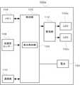
図1は、可視光通信システム1の構成の一例を示す図である。図1に示すように、可視光通信システム1が適用される空間Sには、棚400a、400bが設置されており、フォークリフト100aと、カメラ200a、200b、200c、200d(以下、カメラ200a、200b、200c、200dのそれぞれを限定しない場合には、適宜「カメラ200」と称する)と、ハブ210と、サーバ300とが含まれる。空間Sは、互いに直交する水平方向のX軸及びY軸と、これらX軸及びY軸の双方に直交する鉛直方向のZ軸によって規定され、これらX軸、Y軸及びZ軸の座標によって空間S内の各位置が特定される。 FIG. 1 is a diagram showing an example of the configuration of the visible light communication system 1. As shown in FIG. 1, in the space S to which the visible light communication system 1 is applied,
フォークリフト100aは、鉛直方向(Z軸方向)に移動するフォーク101aと、当該フォーク101aに取り付けられるマーカー(発光体)であるLED(Light Emitting Diode)102a、102bとを含む。フォーク101aが移動してもLED102aとLED102bとのZ軸方向の距離は不変である。サーバ300は、ハブ210を介してカメラ200a~200dを接続する。 The
フォークリフト100aに取り付けられたLED102a、102bは、それぞれ送信対象の情報である自身のZ軸方向の位置に関する情報(高さ情報)としての自身の識別情報(ID:Identification)に対応して、発光の態様を時系列に変化させ、可視光通信により送信する。 The
一方、カメラ200は、空間S全体の撮像を行う。サーバ300は、カメラ200の撮像により得られた空間S全体の画像から、画像におけるLED102a、102bの位置を取得し、更にLED102a、102bの時系列的に変化する発光の内容を復号し、フォークリフト100aからのLED102a、102bのIDを取得する。 On the other hand, the
図2は、フォークリフト100aの構成の一例を示す図である。図2に示すように、フォークリフト100aは、LED102a、102b、制御部103、メモリ104、加速度センサー108、通信部110、駆動部112、及び、電池150を含む。 FIG. 2 is a diagram showing an example of the configuration of the
制御部103は、例えばCPU(Central Processing Unit)によって構成される。制御部103は、メモリ104に記憶されたプログラムに従ってソフトウェア処理を実行することにより、フォークリフト100aが具備する各種機能を制御する。 The
メモリ104は、例えばRAM(Random Access Memory)やROM(Read Only Memory)である。メモリ104は、フォークリフト100aにおける制御等に用いられる各種情報(プログラム等)を記憶する。 The
加速度センサー108はX軸及びY軸によって規定されるXY平面におけるフォークリフト100aの加速度を検出する。 The
通信部110は、例えばLAN(Local Area Network)カードである。通信部110は、サーバ300等との間で無線通信を行う。 The
制御部103内には発光制御部124が構成される。発光制御部124は、フォーク101aの鉛直方向(Z軸方向)の移動を検知し、当該フォーク101aに取り付けられたLED102a、102bの空間SにおけるZ軸方向の位置を特定する。更に、発光制御部124は、空間SにおけるLED102a、102bの高さに対応する、LED102a、102bのZ軸方向の位置に関する情報(高さ情報)を生成する。ここで、発光制御部124は、LED102aについて、当該LED102aの高さ情報であるIDに対応して発光態様を時系列に変化させる発光パターンを決定し、LED102bについて、当該LED102bの高さ情報であるIDに対応して発光態様を時系列に変化させる発光パターンを決定する。 A light
更に、発光制御部124は、発光パターンの情報を駆動部112へ出力する。駆動部112は、発光制御部124からのLED102aの発光パターンの情報に応じて、LED102aの発光の態様を時間的に変化させるための駆動信号を生成し、発光制御部124からのLED102bの発光パターンの情報に応じて、LED102bの発光の態様を時間的に変化させるための駆動信号を生成する。LED102a、102bは、駆動部112から出力される駆動信号に応じて、発光の態様を時間的に変化する光を発する。例えば、発光色は3原色であり、可視光通信における色変調に用いる波長帯の色である赤(R)、緑(G)、青(B)の何れかである。 Further, the light
図3は、カメラ200とサーバ300の構成の一例を示す図である。図3に示すように、カメラ200とサーバ300とはハブ210を介して接続される。カメラ200は、撮像部202及びレンズ203を含む。サーバ300は、制御部302、画像処理部304、メモリ305、操作部306、表示部307及び通信部308を含む。 FIG. 3 is a diagram showing an example of the configuration of the
カメラ200内のレンズ203は、ズームレンズ等により構成される。レンズ203は、サーバ300内の操作部306からのズーム制御操作、及び、制御部302による合焦制御により移動する。レンズ203の移動によって撮像部202が撮像する撮像画角や光学像が制御される。 The
撮像部202は、規則的に二次元配列された複数の受光素子により、撮像面を含む受光面が構成される。受光素子は、例えば、CCD(Charge Coupled Device)、CMOS(Complementary Metal Oxide Semiconductor)等の撮像デバイスである。撮像部202は、レンズ203を介して入光された光学像を、サーバ300内の制御部302からの制御信号に基づいて所定範囲の撮像画角で撮像(受光)し、その撮像画角内の画像信号をデジタルデータに変換してフレームを生成する。また、撮像部202は、撮像とフレームの生成とを時間的に連続して行い、連続するフレームのデジタルデータを画像処理部304に出力する。 In the
画像処理部304は、制御部302からの制御信号に基づいて、撮像部202から出力されたフレームのデジタルデータを制御部302へ出力する。 The
制御部302は、例えばCPU等のプロセッサによって構成される。制御部302は、メモリ305に記憶されたプログラムに従ってソフトウェア処理を実行することにより、サーバ300が具備する各種機能を制御する。 The
メモリ305は、例えばRAMやROMである。メモリ305は、サーバ300における制御等に用いられる各種情報(プログラム等)を記憶する。また、メモリ305は、空間Sにおける各カメラ200の設置位置、撮像方向及び撮影範囲の情報と、LED102aとLED102bとのZ軸方向の距離の情報とを記憶している。 The
操作部306は、テンキーやファンクションキー等によって構成され、ユーザの操作内容を入力するために用いられるインタフェースである。表示部307は、例えば、LCD(Liquid Crystal Display)、PDP(Plasma Display Panel)、EL(Electro Luminescence)ディスプレイ等によって構成される。表示部307は、制御部302から出力された画像信号に従って画像を表示する。通信部308は、例えばLANカードである。通信部308は、外部の通信装置との間で通信を行う。 The
制御部302には、検出部332、高さ情報取得部334及び位置情報取得部336が構成される。 The
検出部332は、撮像部202が出力する複数のフレームのデジタルデータそれぞれについて、当該フレームを構成する各画素の輝度値を取得する。次に、検出部332は、フレームにおいて輝度値が所定値以上である画素の位置をLED102a、102bの位置であるとみなす。 The
更に、検出部332は、フレーム内のLED102a、102bの位置における発光態様の変化に基づいて復号処理を行う。 Further, the
高さ情報取得部334は、検出部332による復号処理により得られた、LED102a、102bが送信した高さ情報を取得する。位置情報取得部336は、LED102aの高さ情報であるIDと、LED102bの高さ情報であるIDとに基づいて、LED102a、102bの三次元の位置を取得する。 The height
図4は、LED102a、102bの三次元の位置取得の態様を示す図である。図4に示す例では、LED102aとLED102bとの距離は不変の値aである。LED102aは高さ情報として自身のIDに対応する発光を行い、LED102bは高さ情報として自身のIDに対応する発光を行う。 FIG. 4 is a diagram showing a mode of three-dimensional position acquisition of
この場合、位置情報取得部336は、画像におけるLED102a、102bの位置と、撮像方向及び撮影範囲の情報とに基づいて、角度θ1、θ2を算出する。 In this case, the position
次に、位置情報取得部336は、X軸及びY軸によって規定されるXY平面におけるカメラ200aとLED102a、102bとの距離Xを、メモリ305に記憶された空間SにおけるLED102aとLED102bとのZ軸方向の距離(ここではa)と、算出したθ1、θ2とを用いて、X=a/(tanθ1-tanθ2)により算出する。 Next, the position
更に、位置情報取得部336は、空間Sにおけるカメラ200aの設置位置のZ座標HcとLED102aのZ座標との差分Z1をZ1=X*tanθ1により算出し、カメラ200aの設置位置のZ座標とLED102bのZ座標との差分Z2をZ2=X*tanθ2により算出する。これにより、空間SにおけるLED102a、102bの三次元の位置が特定される。 Further, the position
図5は、カメラ200及びサーバ300が行う処理の一例を示すフローチャートである。上述したように、フォークリフト100aにおいて、LED102aは自身の高さ情報として自身のIDに対応する発光を行い、LED102bは自身の高さ情報として自身のIDに対応する発光を行う。 FIG. 5 is a flowchart showing an example of processing performed by the
この場合、カメラ200が撮像を行うと(ステップS101)、サーバ300の制御部302内の検出部332は、撮像によって得られたフレームを構成する各画素の輝度値を取得し、輝度値が所定値以上である画素の位置をLED102a、102bの位置であるとみなし、LED102a、102bの位置における発光態様の変化に基づいて復号処理を行う。高さ情報取得部334は、検出部332による復号処理により得られた、LED102a、102bが送信した高さ情報としてのIDを取得する(ステップS102)。 In this case, when the
位置情報取得部336は、LED102a、102bのそれぞれの高さ情報であるID、すなわち2つの高さ情報であるIDを取得したか否かを判定する(ステップS103)。2つの高さ情報であるIDを取得していない場合には(ステップS103;NO)、ステップS102以降の動作が繰り返される。 The position
一方、2つの高さ情報であるIDを取得した場合には(ステップS103;YES)、位置情報取得部336は、2つの高さ情報に対応する高さの差分に基づいて、LED102a、102bの三次元の位置を取得する(ステップS104)。具体的な処理は、上述した通り、位置情報取得部336は、X軸及びY軸によって規定されるXY平面におけるカメラ200とLED102a、102bとの距離Xを、X=a/(tanθ1-tanθ2)により算出し、更に、カメラ200の設置位置のZ座標とLED102aのZ座標との差分Z1をZ1=X*tanθ1により、カメラ200の設置位置のZ座標とLED102bのZ座標との差分Z2をZ2=X*tanθ2によりそれぞれ算出する。 On the other hand, when the IDs that are the two height information are acquired (step S103; YES), the position
このように、第1の実施形態では、フォークリフト100aのフォーク101aに取り付けられたLED102a、102bは、それぞれ自身の高さ情報として自身のIDに対応する発光を行う。一方、サーバ300は、カメラ200の撮像によって得られたフレーム内のLED102a、102bの位置を特定し、更に、画像におけるLED102a、102bの位置と、空間Sにおける各カメラ200の設置位置、撮像方向及び撮影範囲の情報とに基づいて、LED102a、102bの三次元の位置を取得する。このようにして2つのLED102a、102bが用いられることにより、LED102a、102bを撮像可能なカメラ200が1台のみであっても、これらLED102a、102bの三次元の位置、更には、フォークリフト100aあるいはフォーク101aの三次元の位置を取得することができる。 As described above, in the first embodiment, the
次に、第2の実施形態について説明する。図6は、第2の実施形態に係る可視光通信システムの一例を示す図であり、図7は、フォークリフトの構成の一例を示す図である。図6に示す可視光通信システム1及び図7に示すフォークリフト100aは、第1の実施形態と比較すると、フォークリフト100aのフォーク101aにLED102bが取り付けられていない一方、フォークリフト100aの本体にLED102cが取り付けられている。なお、カメラ200及びサーバ300の構成は第1の実施形態と同様である。 Next, the second embodiment will be described. FIG. 6 is a diagram showing an example of a visible light communication system according to a second embodiment, and FIG. 7 is a diagram showing an example of a forklift configuration. In the visible light communication system 1 shown in FIG. 6 and the
本実施形態では、フォーク101aがZ軸方向に移動した場合、LED102aのみが移動し、LED102cはフォークリフト100aの本体に取り付けられているため、移動しない。本実施形態では、サーバ300内のメモリ305には、LED102cのZ座標が基準の高さの固定値として記憶されている。 In the present embodiment, when the
フォークリフト100aの制御部103内の発光制御部124は、フォーク101aの鉛直方向(Z軸方向)の移動を検知し、当該フォーク101aに取り付けられたLED102aの空間SにおけるZ軸方向の位置を特定する。更に、発光制御部124は、空間SにおけるLED102a、102cの高さに対応する、LED102a、102cのZ軸方向の位置に関する情報(高さ情報)を生成する。ここで、発光制御部124は、自身の識別情報を含んだIDを高さ情報として生成する。また、発光制御部124は、LED102cについては当該LED102cが基準の高さであることを示す情報と自身の識別情報とを含んだIDを高さ情報として生成する。更に、発光制御部124は、LED102aについて、当該LED102aの高さ情報であるIDに対応して発光態様を時系列に変化させる発光パターンを決定し、LED102cについて、当該LED102cの高さ情報であるIDに対応して発光態様を時系列に変化させる発光パターンを決定する。 The light emitting
更に、駆動部112は、発光制御部124からのLED102aの発光パターンの情報に応じて、LED102aの発光の態様を時間的に変化させるための駆動信号を生成し、発光制御部124からのLED102bの発光パターンの情報に応じて、LED102bの発光の態様を時間的に変化させるための駆動信号を生成する。LED102a、102cは、駆動部112から出力される駆動信号に応じて、発光の態様が時間的に変化する光を発する。 Further, the
サーバ300の制御部302における検出部332及び高さ情報取得部334は、第1の実施形態と同様の処理を行う。 The
位置情報取得部336は、LED102aの高さ情報であるIDと、LED102cの高さ情報であるIDとに基づいて、LED102a、102cの三次元の位置を取得する。 The position
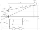
図8は、LED102a、102cの三次元の位置取得の態様を示す図である。図8に示す例では、LED102cは基準の高さに存在する。基準の高さを示すLED102cのZ座標Zpの情報はサーバ300内のメモリ305に記憶されている。LED102aは高さ情報として自身のIDに対応する発光を行い、LED102cは高さ情報として自身のIDに対応する発光を行う。 FIG. 8 is a diagram showing a mode of three-dimensional position acquisition of
この場合、位置情報取得部336は、画像におけるLED102a、102cの位置と、撮像方向及び撮影範囲の情報とに基づいて、角度θ1、θ2を算出する。 In this case, the position
次に、位置情報取得部336は、X軸及びY軸によって規定されるXY平面におけるカメラ200aとLED102a、102cとの距離Xを、空間Sにおけるカメラ200aの設置位置のZ座標Hcと、LED102cの基準の高さを示すZ座標Zpと、算出したθ1とを用いて、X=(Hc-Zp)/tanθ1により算出する。 Next, the position
更に、位置情報取得部336は、空間Sにおけるカメラ200の設置位置のZ座標HcとLED102aのZ座標との差分Z2を、算出したXとθ2とを用いて、Z2=X*tanθ2により算出する。これにより、空間SにおけるLED102a、102cの三次元の位置が特定される。 Further, the position
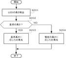
図9は、フォークリフト100aが行う処理の一例を示すフローチャートである。図9に示す処理は、LED102aの発光制御に関する処理であるがLED102cの発光制御も同様である。 FIG. 9 is a flowchart showing an example of the processing performed by the
図9に示すように、フォークリフト100aの制御部103内の発光制御部124は、LED102aの空間SにおけるZ軸方向の位置(高さ)を検出する(ステップS201)。 As shown in FIG. 9, the light
次に、発光制御部124は、LED102aが基準の高さであるか否かを判定する(ステップS202)。LED102aが基準の高さである場合(ステップS202;YES)、発光制御部124は、基準の高さであることを示す情報とLED102aの識別情報とを含んだIDを高さ情報として生成し、当該IDに対応する発光パターンでLED102aを発光させる(ステップS203)。 Next, the light
一方、LED102aが基準の高さでない場合(ステップS202;NO)、発光制御部124は、LED102aのZ座標と識別情報とを含んだIDを高さ情報として生成し、当該IDに対応する発光パターンでLED102aを発光させる(ステップS204)。 On the other hand, when the
その後、サーバ300は、上述した通り、LED102a、102cの三次元の位置を取得する。 After that, the
このように、第2の実施形態では、フォークリフト100aのフォーク101aに取り付けられたLED102aと本体に取り付けられたLED102cとは、それぞれ自身の高さ情報として自身のIDに対応する発光を行う。一方、サーバ300は、カメラ200の撮像によって得られたフレーム内のLED102a、102cの位置を特定し、メモリ305に記憶されたLED102cの基準の高さを示すZ座標Zpと、画像におけるLED102a、102cの位置と、空間Sにおける各カメラ200の設置位置と、撮像方向及び撮影範囲の情報とに基づいて、LED102a、102cの三次元の位置を取得する。このようにして2つのLED102a、102cが用いられることにより、LED102a、102cを撮像可能なカメラ200が1台のみであっても、これらLED102a、102cの三次元の位置、更には、フォークリフト100aあるいはフォーク101aの三次元の位置を取得することができる。 As described above, in the second embodiment, the
次に、第3の実施形態について説明する。図10は、第3の実施形態に係る可視光通信システムの一例を示す図であり、図11は、フォークリフトの構成の一例を示す図である。図10に示す可視光通信システム1及び図11に示すフォークリフト100aは、第1の実施形態と比較すると、フォークリフト100aのフォーク101aにLED102bが取り付けられていない一方、フォークリフト100a内にブザー114が取り付けられている。また、通信部110を利用してフォーク101aの上下方向への移動量情報を取得することができる。なお、カメラ200及びサーバ300の構成は第1の実施形態と同様である。 Next, a third embodiment will be described. FIG. 10 is a diagram showing an example of a visible light communication system according to a third embodiment, and FIG. 11 is a diagram showing an example of a forklift configuration. In the visible light communication system 1 shown in FIG. 10 and the
本実施形態では、フォーク101aがZ軸方向に移動した場合、LED102aが移動する。本実施形態では、サーバ300内のメモリ305には、LED102aの基準の高さのZ座標が固定値として記憶されている。基準の高さとは、フォーク101aが最も下の位置(初期位置)に存在する場合のLED101aの高さである。 In the present embodiment, when the
フォークリフト100aの制御部103内の発光制御部124は、LED102aの三次元の位置取得が行われる場合に、加速度センサー108からの加速度に基づいて、フォークリフト100aのXY平面における移動、停止を判別する。フォークリフト100aがXY平面において移動中である場合には、発光制御部124は、ブザー114を鳴動させて作業者にフォークリフト100aの停止を促す。 The light emitting
フォークリフト100aがXY平面において停止した後、発光制御部124は、フォーク101aの鉛直方向(Z軸方向)の移動を検知し、当該フォーク101aに取り付けられたLED102aの空間SにおけるZ軸方向の位置を特定する。ここで、発光制御部124は、フォーク101aが初期位置に存在する場合とフォーク101aが初期位置から移動した場合のそれぞれにおいて、LED102aの空間SにおけるZ軸方向の位置を特定する。 After the
更に、発光制御部124は、空間SにおけるLED102aの高さに対応する、LED102aのZ軸方向の位置に関する情報(高さ情報)を生成する。ここで、発光制御部124は、フォーク101aが初期位置に存在する場合に対応して、LED102aが基準の高さであることを示す情報と自身の識別情報とを含んだIDを高さ情報として生成する。また、発光制御部124は、フォーク101aが初期位置から移動した場合に対応して、LED102aのZ座標と自身の識別情報とを含んだIDを高さ情報として生成する。更に、発光制御部124は、フォーク101aが初期位置に存在する場合には、LED102aの高さ情報であるIDに対応して発光態様を時系列に変化させる発光パターンを決定する。また、発光制御部124は、フォーク101aが初期位置から移動した場合には、LED102aの高さ情報であるIDに対応して発光態様を時系列に変化させる発光パターンを決定する。 Further, the light
更に、駆動部112は、発光制御部124からのLED102aの発光パターンの情報に応じて、LED102aの発光の態様を時間的に変化させるための駆動信号を生成する。LED102aは、駆動部112から出力される駆動信号に応じて、発光の態様が時間的に変化する光を発する。これにより、LED102aは、フォーク101aが初期位置に存在する場合と、フォーク101aが初期位置から移動した場合とのそれぞれにおいて、LED102aの高さ情報であるIDに対応して発光態様がを時系列に変化させる発光を行うことになる。 Further, the
サーバ300の制御部302における検出部332及び高さ情報取得部334は、第1の実施形態と同様の処理を行う。 The
位置情報取得部336は、LED102aの高さ情報であるIDに基づいて、LED102aの三次元の位置を取得する。 The position
図12は、LED102aの三次元の位置取得の態様を示す図である。図12に示す例では、LED102aは、フォークリフト100aがXY平面において停止している間のフォーク101aの移動に伴って、基準の高さであるAの位置からBの位置に移動する。基準の高さを示すLED102cのZ座標Zpの情報はサーバ300内のメモリ305に記憶されている。LED102aはAの位置とBの位置のそれぞれにおいて、高さ情報として自身のIDに対応する発光を行う。 FIG. 12 is a diagram showing an aspect of three-dimensional position acquisition of the
この場合、位置情報取得部336は、Aの位置にあるLED102aとBの位置にあるLED102aの画像における位置と、撮像方向及び撮影範囲の情報とに基づいて、角度θ1、θ2を算出する。 In this case, the position
次に、位置情報取得部336は、X軸及びY軸によって規定されるXY平面におけるカメラ200aとLED102aとの距離Xを、空間Sにおけるカメラ200aの設置位置のZ座標Hcと、Aの位置のLED102aの基準の高さを示すZ座標Zpと、角度θ1とを用いて、X=(Hc-Zp)/tanθ1により算出する。 Next, the position
更に、位置情報取得部336は、空間Sにおけるカメラ200aの設置位置のZ座標HcとLED102aのZ座標との差分Z2を、算出したXとθ2とを用いて、Z2=X*tanθ2により算出する。これにより、空間SにおけるLED102aの三次元の位置が特定される。 Further, the position
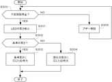
図13は、フォークリフト100aが行う処理の一例を示すフローチャートである。図13に示すように、フォークリフト100aの制御部103内の発光制御部124は、フォークリフト100aのXY平面における移動(平面移動)を停止しているか否かを判定する(ステップS300)。 FIG. 13 is a flowchart showing an example of the processing performed by the
フォークリフト100aが平面移動を停止している場合には(ステップS300;YES)、発光制御部124は、LED102aの空間SにおけるZ軸方向の位置(高さ)を検出する(ステップS301)。 When the
次に、発光制御部124は、LED102aが基準の高さであるか否かを判定する(ステップS302)。LED102aが基準の高さである場合(ステップS302;YES)、発光制御部124は、基準の高さであることを示す情報とLED102aの識別情報とを含んだIDを高さ情報として生成し、当該IDに対応する発光パターンでLED102aを発光させる(ステップS303)。 Next, the light
一方、LED102aが基準の高さでない場合(ステップS302;NO)、発光制御部124は、識別情報を含んだIDを高さ情報として生成し、当該IDに対応する発光パターンでLED102aを発光させる(ステップS304)。 On the other hand, when the
また、フォークリフト100aが平面移動中である場合には(ステップS300;NO)、発光制御部124は、ブザー114を鳴動させて作業者にフォークリフト100aの停止を促す(ステップS305)。その後は、ステップS300以降の動作が繰り返される。 When the
その後、サーバ300は、上述した通り、LED102aの三次元の位置を取得する。 After that, the
このように、第3の実施形態では、フォークリフト100aのフォーク101aに取り付けられたLED102aは、フォークリフト100aがXY平面での移動を停止している場合に、フォーク101aが初期位置に存在する場合と、初期位置から移動した場合のそれぞれに対応して、自身のIDに対応する発光を行う。一方、サーバ300は、カメラ200の撮像によって得られたフレーム内のLED102aについて、フォーク101aが初期位置に存在する場合の位置と、メモリ305に記憶されたLED102aの基準の高さを示すZ座標Zpと、画像における初期位置と移動後のLED102aの位置と、空間Sにおける各カメラ200の設置位置と、撮像方向及び撮影範囲の情報とに基づいて、LED102aの三次元の位置を取得する。このようにして1つのLED102aにおけるフォーク101aが初期位置に存在する場合の位置と、初期位置から移動した場合の位置が用いられることにより、LED102aを撮像可能なカメラ200が1台のみであっても、LED102aの三次元の位置、更には、フォークリフト100aあるいはフォーク101aの三次元の位置を取得することができる。 As described above, in the third embodiment, the
なお、本発明は、上記実施形態の説明及び図面によって限定されるものではなく、上記実施形態及び図面に適宜変更等を加えることは可能である。 The present invention is not limited to the description and drawings of the above-described embodiment, and it is possible to appropriately modify the above-described embodiments and drawings.
例えば、上述した第2の実施形態において、フォークリフト100a内の発光制御部124は、LED102cが基準の高さであることを示す情報と自身の識別情報とを含んだIDを高さ情報として生成し、対応する発光パターンによってLED102cを発光させた。しかし、これに限定されず、基準の高さに存在するLED102cについてはLED102aとは異なる発光態様、例えば異なる色で発光させることで、サーバ300が、LED102cが基準の高さに存在することを認識することができるようにしてもよい。 For example, in the second embodiment described above, the light
また、上述した第3の実施形態において、フォークリフト100a内の発光制御部124は、LED102aが基準の高さであることを示す情報と自身の識別情報とを含んだIDを高さ情報として生成し、対応する発光パターンによってLED102aを発光させた。しかし、これに限定されず、LED102aが基準の高さに存在する場合には、それ以外の場合とは異なる発光態様、例えば異なる色で発光させることで、サーバ300が、LED102aが基準の高さに存在することを認識することができるようにしてもよい。 Further, in the third embodiment described above, the light
また、フォークリフト100aは、LED102aの空間SにおけるZ軸方向の位置(高さ)を示すZ座標をサーバ300へ送信するようにしてもよい。送信方法は、可視光通信でもよいし、無線通信でもよい。 Further, the
また、上述した実施形態では、可視光である赤、緑、青の光を通信に用いる場合について説明したが、他の色の可視光を用いてもよい。また、情報が輝度の時間方向の変化のみによって変調される可視光通信においても本発明を適用することができる。 Further, in the above-described embodiment, the case where visible light such as red, green, and blue light is used for communication has been described, but visible light of other colors may be used. The present invention can also be applied to visible light communication in which information is modulated only by a change in brightness in the time direction.
また、フォークリフト100a内の光源はLEDに限定されない。例えば、表示装置を構成するLCD、PDP、ELディスプレイ等の一部に光源が構成されていてもよい。 Further, the light source in the
また、サーバ300は、カメラ200が内装されたものであってもよい。 Further, the
また、上記実施形態において、実行されるプログラムは、フレキシブルディスク、CD-ROM(Compact Disc - Read Only Memory)、DVD(Digital Versatile Disc)、MO(Magneto - Optical disc)等のコンピュータで読み取り可能な記録媒体に格納して配布し、そのプログラムをインストールすることにより、上述の処理を実行するシステムを構成することとしてもよい。 Further, in the above embodiment, the program to be executed is a computer-readable recording such as a flexible disc, a CD-ROM (Compact Disc-Read Only Memory), a DVD (Digital Versatile Disc), or an MO (Magneto-Optical disc). By storing it in a medium, distributing it, and installing the program, a system that executes the above-mentioned processing may be configured.
また、プログラムをインターネット等のネットワーク上の所定のサーバが有するディスク装置等に格納しておき、例えば、搬送波に重畳させて、ダウンロード等するようにしてもよい。 Further, the program may be stored in a disk device or the like owned by a predetermined server on a network such as the Internet, and may be superimposed on a carrier wave for downloading or the like.
なお、上述の機能を、OS(Operating System)が分担して実現する場合又はOSとアプリケーションとの協働により実現する場合等には、OS以外の部分のみを媒体に格納して配布してもよく、また、ダウンロード等してもよい。 If the above functions are shared by the OS (Operating System) or realized by collaboration between the OS and the application, only the parts other than the OS may be stored and distributed in the medium. Well, you may download it.
以上、本発明の好ましい実施形態について説明したが、本発明は係る特定の実施形態に限定されるものではなく、本発明には、特許請求の範囲に記載された発明とその均等の範囲が含まれる。以下に、本願出願の当初の特許請求の範囲に記載された発明を付記する。 Although the preferred embodiment of the present invention has been described above, the present invention is not limited to the specific embodiment, and the present invention includes the invention described in the claims and the equivalent range thereof. Will be. The inventions described in the original claims of the present application are described below.
(付記1)
空間を移動可能であって、前記空間における自身の識別情報に対応する光を発光する第1の発光手段と、
撮像手段と、
前記撮像手段によって取得される画像の撮像範囲から、前記第1の発光手段が第1の高さに存在する場合の前記第1の発光手段の発光体像を検出するとともに、前記第1の発光手段が第2の高さに存在する場合の前記第1の発光手段の発光体像を検出する検出手段と、
前記検出手段により検出された前記第1の発光手段が前記第1の高さに存在する場合の前記画像における前記第1の発光手段の発光体像の位置と、前記検出手段により検出された前記第1の発光手段が前記第2の高さに存在する場合の前記画像における前記第1の発光手段の発光体像の位置とに基づいて、前記空間における前記第1の発光手段の三次元の位置を取得する位置取得手段と、
を備えることを特徴とする位置測定システム。(Appendix 1)
A first light emitting means that can move in space and emits light corresponding to its own identification information in the space.
Imaging means and
From the image pickup range of the image acquired by the image pickup means, the light emitting body image of the first light emitting means when the first light emitting means is present at the first height is detected, and the first light emitting means is emitted. A detection means for detecting a light emitting body image of the first light emitting means when the means is present at a second height, and a detection means.
The position of the light emitting body image of the first light emitting means in the image when the first light emitting means detected by the detecting means is present at the first height, and the above-mentioned detected by the detecting means. Three-dimensional of the first light emitting means in the space based on the position of the light emitting body image of the first light emitting means in the image when the first light emitting means is present at the second height. Position acquisition means to acquire the position and
A position measurement system characterized by being equipped with.
(付記2)
空間を移動可能であって、前記空間における自身の識別情報に対応する光を発光する第1の発光手段と、
前記第1の発光手段と鉛直方向に所定の間隔を維持しながら移動可能な第2の発光手段と、
撮像手段と、
前記撮像手段によって取得される画像の撮像範囲から、前記画像における前記第1の発光手段の発光体像とともに前記第2の発光手段の発光体像を検出する検出手段と、
前記検出手段により検出された前記画像における前記第1の発光手段の発光体像の位置と、前記検出手段により検出された前記画像における前記第2の発光手段の発光体像の位置とに基づいて、前記空間における前記第1の発光手段の三次元の位置を取得する位置取得手段と、
を備えることを特徴とする位置測定システム。(Appendix 2)
A first light emitting means that can move in space and emits light corresponding to its own identification information in the space.
A second light emitting means that can move while maintaining a predetermined distance in the vertical direction from the first light emitting means, and a second light emitting means.
Imaging means and
A detection means for detecting a light emitting body image of the first light emitting means and a light emitting body image of the second light emitting means in the image from the image pickup range of the image acquired by the image pickup means.
Based on the position of the illuminant image of the first light emitting means in the image detected by the detection means and the position of the illuminant image of the second light emitting means in the image detected by the detection means. , A position acquisition means for acquiring a three-dimensional position of the first light emitting means in the space, and
A position measurement system characterized by being equipped with.
(付記3)
空間を移動可能であって、前記空間における自身の識別情報に対応する光を発光する第1の発光手段と、
既知の高さに設置され、前記空間における平面上の位置が前記第1の発光手段と同一であると見なされる第2の発光手段と、
撮像手段と、
前記撮像手段によって取得される画像の撮像範囲から、前記画像における前記第1の発光手段の発光体像とともに前記第2の発光手段の発光体像を検出する検出手段と、
前記検出手段により検出された前記画像における前記第1の発光手段の発光体像の位置と、前記検出手段により検出された前記画像における前記第2の発光手段の発光体像の位置とに基づいて、前記空間における前記第1の発光手段の三次元の位置を取得する位置取得手段と、
を備えることを特徴とする位置測定システム。(Appendix 3)
A first light emitting means that can move in space and emits light corresponding to its own identification information in the space.
A second light emitting means, which is installed at a known height and whose position on a plane in the space is considered to be the same as that of the first light emitting means.
Imaging means and
A detection means for detecting a light emitting body image of the first light emitting means and a light emitting body image of the second light emitting means in the image from the image pickup range of the image acquired by the image pickup means.
Based on the position of the illuminant image of the first light emitting means in the image detected by the detection means and the position of the illuminant image of the second light emitting means in the image detected by the detection means. , A position acquisition means for acquiring a three-dimensional position of the first light emitting means in the space, and
A position measurement system characterized by being equipped with.
(付記4)
前記検出手段により検出された前記第1の発光手段の発光体像に基づいて、前記識別情報を取得する取得手段を備え、
前記位置取得手段は、前記検出手段により検出された前記画像における前記第1の発光手段の発光体像の位置と、前記取得手段により取得された前記識別情報とに基づいて、前記空間における前記第1の発光手段の三次元の位置を取得することを特徴とする付記1に記載の位置測定システム。(Appendix 4)
An acquisition means for acquiring the identification information based on the illuminant image of the first light emitting means detected by the detection means is provided.
The position acquisition means is the first in the space based on the position of the illuminant image of the first light emitting means in the image detected by the detection means and the identification information acquired by the acquisition means. The position measurement system according to Appendix 1, wherein the position of the light emitting means of 1 is acquired in three dimensions.
(付記5)
前記位置取得手段は、更に、前記撮像手段の前記空間における設置位置と、撮像方向とに基づいて、前記空間における前記第1の発光手段の三次元の位置を取得することを特徴とする付記1~4の何れか1つに記載の位置測定システム。(Appendix 5)
Addendum 1 characterized in that the position acquisition means further acquires a three-dimensional position of the first light emitting means in the space based on the installation position of the image pickup means in the space and the image pickup direction. The position measurement system according to any one of 4 to 4.
(付記6)
撮像手段と、
前記撮像手段によって取得される画像の撮像範囲から、空間を移動可能であって、前記空間における自身の識別情報に対応する光を発光する発光手段が第1の高さに存在する場合の前記発光手段の発光体像を検出するとともに、前記第1の発光手段が第2の高さに存在する場合の前記発光手段の発光体像を検出する検出手段と、
前記検出手段により検出された前記発光手段が前記第1の高さに存在する場合の前記画像における前記発光手段の発光体像の位置と、前記検出手段により検出された前記発光手段が前記第2の高さに存在する場合の前記画像における前記発光手段の発光体像の位置とに基づいて、前記空間における前記発光手段の三次元の位置を取得する位置取得手段と、
を備えることを特徴とする位置測定装置。(Appendix 6)
Imaging means and
The light emission when the light emitting means which can move in space from the image pickup range of the image acquired by the image pickup means and emits light corresponding to its own identification information in the space exists at the first height. A detection means for detecting a light emitting body image of the means and a detecting means for detecting a light emitting body image of the light emitting means when the first light emitting means is present at a second height.
The position of the light emitting body image of the light emitting means in the image when the light emitting means detected by the detecting means is present at the first height, and the light emitting means detected by the detecting means are the second. A position acquisition means for acquiring a three-dimensional position of the light emitting means in the space based on the position of the light emitting body image of the light emitting means in the image when the light emitting means is present at the height of the above.
A position measuring device characterized by comprising.
(付記7)
撮像手段と、
前記撮像手段によって取得される画像の撮像範囲から、前記画像における、空間を移動可能であって、前記空間における自身の識別情報に対応する光を発光する第1の発光手段の発光体像と、前記第1の発光手段と鉛直方向に所定の間隔を維持しながら移動可能な第2の発光手段の発光体像とを検出する検出手段と、
前記検出手段により検出された前記画像における前記第1の発光手段の発光体像の位置と、前記検出手段により検出された前記画像における前記第2の発光手段の発光体像の位置とに基づいて、前記空間における前記第1の発光手段の三次元の位置を取得する位置取得手段と、
を備えることを特徴とする位置測定装置。(Appendix 7)
Imaging means and
An image of a light emitting body of a first light emitting means that can move in space in the image and emits light corresponding to its own identification information in the space from the imaging range of the image acquired by the image pickup means. A detection means for detecting the light emitting means of the first light emitting means and a light emitting body image of the second light emitting means that can move while maintaining a predetermined interval in the vertical direction.
Based on the position of the illuminant image of the first light emitting means in the image detected by the detection means and the position of the illuminant image of the second light emitting means in the image detected by the detection means. , A position acquisition means for acquiring a three-dimensional position of the first light emitting means in the space, and
A position measuring device characterized by comprising.
(付記8)
撮像手段と、
前記撮像手段によって取得される画像の撮像範囲から、前記画像における、空間を移動可能であって、前記空間における自身の識別情報に対応する光を発光する第1の発光手段の発光体像と、既知の高さに設置され、前記空間における平面上の位置が前記第1の発光手段と同一であると見なされる第2の発光手段の発光体像を検出する検出手段と、
前記検出手段により検出された前記画像における前記第1の発光手段の発光体像の位置と、前記検出手段により検出された前記画像における前記第2の発光手段の発光体像の位置とに基づいて、前記空間における前記第1の発光手段の三次元の位置を取得する位置取得手段と、
を備えることを特徴とする位置測定装置。(Appendix 8)
Imaging means and
An image of a light emitting body of a first light emitting means that can move in space in the image and emits light corresponding to its own identification information in the space from the imaging range of the image acquired by the image pickup means. A detection means installed at a known height and detecting a light emitting body image of a second light emitting means whose position on a plane in the space is considered to be the same as that of the first light emitting means.
Based on the position of the illuminant image of the first light emitting means in the image detected by the detection means and the position of the illuminant image of the second light emitting means in the image detected by the detection means. , A position acquisition means for acquiring a three-dimensional position of the first light emitting means in the space, and
A position measuring device characterized by comprising.
(付記9)
撮像ステップと、
前記撮像ステップにおいて取得される画像の撮像範囲から、空間を移動可能であって、前記空間における自身の識別情報に対応する光を発光する発光手段が第1の高さに存在する場合の前記発光手段の発光体像を検出するとともに、前記発光手段が第2の高さに存在する場合の前記発光手段の発光体像を検出する検出ステップと、
前記検出ステップにおいて検出された前記発光手段が前記第1の高さに存在する場合の前記画像における前記発光手段の発光体像の位置と、前記検出ステップにおいて検出された前記発光手段が前記第2の高さに存在する場合の前記画像における前記発光手段の発光体像の位置とに基づいて、前記空間における前記発光手段の三次元の位置を取得する位置取得ステップと、
を含むことを特徴とする位置測定方法。(Appendix 9)
Imaging step and
The light emission when there is a light emitting means at a first height that can move in space from the image pickup range of the image acquired in the image pickup step and emits light corresponding to its own identification information in the space. A detection step of detecting a light emitting body image of the means and detecting a light emitting body image of the light emitting means when the light emitting means is present at a second height.
The position of the light emitting body image of the light emitting means in the image when the light emitting means detected in the detection step is present at the first height, and the light emitting means detected in the detection step is the second. A position acquisition step of acquiring a three-dimensional position of the light emitting means in the space based on the position of the light emitting body image of the light emitting means in the image when the light emitting means is present at the height of
A position measuring method comprising.
(付記10)
撮像ステップと、
前記撮像ステップにおいて取得される画像の撮像範囲から、前記画像における、空間を移動可能であって、前記空間における自身の識別情報に対応する光を発光する第1の発光手段の発光体像と、前記第1の発光手段と鉛直方向に所定の間隔を維持しながら移動可能な第2の発光手段の発光体像とを検出する検出ステップと、
前記検出ステップにおいて検出された前記画像における前記第1の発光手段の発光体像の位置と、前記検出ステップにおいて検出された前記画像における前記第2の発光手段の発光体像の位置とに基づいて、前記空間における前記第1の発光手段の三次元の位置を取得する位置取得ステップと、
を含むことを特徴とする位置測定方法。(Appendix 10)
Imaging step and
From the imaging range of the image acquired in the imaging step, an image of a light emitting body of a first light emitting means that can move in space in the image and emits light corresponding to its own identification information in the space. A detection step for detecting a light emitting body image of the first light emitting means and a second light emitting means that can move while maintaining a predetermined interval in the vertical direction.
Based on the position of the illuminant image of the first light emitting means in the image detected in the detection step and the position of the illuminant image of the second light emitting means in the image detected in the detection step. , A position acquisition step for acquiring a three-dimensional position of the first light emitting means in the space, and
A position measuring method comprising.
(付記11)
撮像ステップと、
前記撮像ステップにおいて取得される画像の撮像範囲から、前記画像における、空間を移動可能であって、前記空間における自身の識別情報に対応する光を発光する第1の発光手段の発光体像と、既知の高さに設置され、前記空間における平面上の位置が前記第1の発光手段と同一であると見なされる第2の発光手段の発光体像を検出する検出ステップと、
前記検出ステップにおいて検出された前記画像における前記第1の発光手段の発光体像の位置と、前記検出ステップにおいて検出された前記画像における前記第2の発光手段の発光体像の位置とに基づいて、前記空間における前記第1の発光手段の三次元の位置を取得する位置取得手段と、
を含むことを特徴とする位置測定方法。(Appendix 11)
Imaging step and
From the imaging range of the image acquired in the imaging step, an image of a light emitting body of a first light emitting means that can move in space in the image and emits light corresponding to its own identification information in the space. A detection step for detecting a light emitter image of a second light emitting means, which is installed at a known height and whose position on a plane in the space is considered to be the same as that of the first light emitting means.
Based on the position of the illuminant image of the first light emitting means in the image detected in the detection step and the position of the illuminant image of the second light emitting means in the image detected in the detection step. , A position acquisition means for acquiring a three-dimensional position of the first light emitting means in the space, and
A position measuring method comprising.
(付記12)
コンピュータを、
撮像手段、
前記撮像手段によって取得される画像の撮像範囲から、空間を移動可能であって、前記空間における自身の識別情報に対応する光を発光する発光手段が第1の高さに存在する場合の前記発光手段の発光体像を検出するとともに、前記発光手段が第2の高さに存在する場合の前記発光手段の発光体像を検出する検出手段、
前記検出手段により検出された前記発光手段が前記第1の高さに存在する場合の前記画像における前記発光手段の発光体像の位置と、前記検出手段により検出された前記発光手段が前記第2の高さに存在する場合の前記画像における前記発光手段の発光体像の位置とに基づいて、前記空間における前記発光手段の三次元の位置を取得する位置取得手段、
として機能させることを特徴とするプログラム。(Appendix 12)
Computer,
Imaging means,
The light emission when the light emitting means which can move in space from the image pickup range of the image acquired by the image pickup means and emits light corresponding to its own identification information in the space exists at the first height. A detection means that detects a light emitting body image of the means and also detects a light emitting body image of the light emitting means when the light emitting means is present at a second height.
The position of the light emitting body image of the light emitting means in the image when the light emitting means detected by the detecting means is present at the first height, and the light emitting means detected by the detecting means are the second. A position acquisition means for acquiring a three-dimensional position of the light emitting means in the space based on the position of the light emitting body image of the light emitting means in the image when the light emitting means is present at the height of the above.
A program characterized by functioning as.
(付記13)
コンピュータを、
撮像手段、
前記撮像手段によって取得される画像の撮像範囲から、前記画像における、空間を移動可能であって、前記空間における自身の識別情報に対応する光を発光する第1の発光手段の発光体像と、前記第1の発光手段と鉛直方向に所定の間隔を維持しながら移動可能な第2の発光手段の発光体像とを検出する検出手段、
前記検出手段により検出された前記画像における前記第1の発光手段の発光体像の位置と、前記検出手段により検出された前記画像における前記第2の発光手段の発光体像の位置とに基づいて、前記空間における前記第1の発光手段の三次元の位置を取得する位置取得手段、
として機能させることを特徴とするプログラム。(Appendix 13)
Computer,
Imaging means,
An image of a light emitting body of a first light emitting means that can move in space in the image and emits light corresponding to its own identification information in the space from the imaging range of the image acquired by the image pickup means. A detection means for detecting a light emitting body image of the first light emitting means and a second light emitting means that can move while maintaining a predetermined interval in the vertical direction.
Based on the position of the illuminant image of the first light emitting means in the image detected by the detection means and the position of the illuminant image of the second light emitting means in the image detected by the detection means. , A position acquisition means for acquiring a three-dimensional position of the first light emitting means in the space,
A program characterized by functioning as.
(付記14)
コンピュータを、
撮像手段、
前記撮像手段によって取得される画像の撮像範囲から、前記画像における、空間を移動可能であって、前記空間における自身の識別情報に対応する光を発光する第1の発光手段の発光体像と、既知の高さに設置され、前記空間における平面上の位置が前記第1の発光手段と同一であると見なされる第2の発光手段の発光体像を検出する検出手段、
前記検出手段により検出された前記画像における前記第1の発光手段の発光体像の位置と、前記検出手段により検出された前記画像における前記第2の発光手段の発光体像の位置とに基づいて、前記空間における前記第1の発光手段の三次元の位置を取得する位置取得手段、
として機能させることを特徴とするプログラム。(Appendix 14)
Computer,
Imaging means,
An image of a light emitting body of a first light emitting means that can move in space in the image and emits light corresponding to its own identification information in the space from the imaging range of the image acquired by the image pickup means. A detecting means, which is installed at a known height and detects a light emitting body image of a second light emitting means whose position on a plane in the space is considered to be the same as that of the first light emitting means.
Based on the position of the illuminant image of the first light emitting means in the image detected by the detection means and the position of the illuminant image of the second light emitting means in the image detected by the detection means. , A position acquisition means for acquiring a three-dimensional position of the first light emitting means in the space,
A program characterized by functioning as.
1…可視光通信システム、100a…フォークリフト、101a…フォーク、102a、102b、102c…LED、103、302…制御部、104、305…メモリ、200、200a、200b、200c、200d…カメラ、108…加速度センサー、110、308…通信部、112…駆動部、114…ブザー、124…発光制御部、150…電池、202…撮像部、203…レンズ、210…ハブ、300…サーバ、304…画像処理部、306…操作部、307…表示部、332…検出部、334…高さ情報取得部、336…位置情報取得部、400a、400b…棚、S…空間 1 ... Visible light communication system, 100a ... Forklift, 101a ... Fork, 102a, 102b, 102c ... LED, 103, 302 ... Control unit, 104, 305 ... Memory, 200, 200a, 200b, 200c, 200d ... Camera, 108 ... Accelerometer, 110, 308 ... Communication unit, 112 ... Drive unit, 114 ... Buzzer, 124 ... Light emission control unit, 150 ... Battery, 202 ... Imaging unit, 203 ... Lens, 210 ... Hub, 300 ... Server, 304 ... Image processing Unit, 306 ... Operation unit, 307 ... Display unit, 332 ... Detection unit, 334 ... Height information acquisition unit, 336 ... Position information acquisition unit, 400a, 400b ... Shelf, S ... Space
Claims (14)
Translated fromJapanese撮像手段と、
前記撮像手段によって取得される画像の撮像範囲から、前記第1の発光手段が第1の高さに存在する場合の前記第1の発光手段の発光体像を検出するとともに、前記第1の発光手段が第2の高さに存在する場合の前記第1の発光手段の発光体像を検出する検出手段と、
前記検出手段により検出された前記第1の発光手段が前記第1の高さに存在する場合の前記画像における前記第1の発光手段の発光体像の位置と、前記検出手段により検出された前記第1の発光手段が前記第2の高さに存在する場合の前記画像における前記第1の発光手段の発光体像の位置とに基づいて、前記空間における前記第1の発光手段の三次元の位置を取得する位置取得手段と、
を備えることを特徴とする位置測定システム。A first light emitting means that can move in space and emits light corresponding to its own identification information in the space.
Imaging means and
From the image pickup range of the image acquired by the image pickup means, the light emitting body image of the first light emitting means when the first light emitting means is present at the first height is detected, and the first light emitting means is emitted. A detection means for detecting a light emitting body image of the first light emitting means when the means is present at a second height, and a detection means.
The position of the light emitting body image of the first light emitting means in the image when the first light emitting means detected by the detecting means is present at the first height, and the above-mentioned detected by the detecting means. Three-dimensional of the first light emitting means in the space based on the position of the light emitting body image of the first light emitting means in the image when the first light emitting means is present at the second height. Position acquisition means to acquire the position and
A position measurement system characterized by being equipped with.
前記第1の発光手段と鉛直方向に所定の間隔を維持しながら移動可能な第2の発光手段と、
撮像手段と、
前記撮像手段によって取得される画像の撮像範囲から、前記画像における前記第1の発光手段の発光体像とともに前記第2の発光手段の発光体像を検出する検出手段と、
前記検出手段により検出された前記画像における前記第1の発光手段の発光体像の位置と、前記検出手段により検出された前記画像における前記第2の発光手段の発光体像の位置とに基づいて、前記空間における前記第1の発光手段の三次元の位置を取得する位置取得手段と、
を備えることを特徴とする位置測定システム。A first light emitting means that can move in space and emits light corresponding to its own identification information in the space.
A second light emitting means that can move while maintaining a predetermined distance in the vertical direction from the first light emitting means, and a second light emitting means.
Imaging means and
A detection means for detecting a light emitting body image of the first light emitting means and a light emitting body image of the second light emitting means in the image from the image pickup range of the image acquired by the image pickup means.
Based on the position of the illuminant image of the first light emitting means in the image detected by the detection means and the position of the illuminant image of the second light emitting means in the image detected by the detection means. , A position acquisition means for acquiring a three-dimensional position of the first light emitting means in the space, and
A position measurement system characterized by being equipped with.
既知の高さに設置され、前記空間における平面上の位置が前記第1の発光手段と同一であると見なされる第2の発光手段と、
撮像手段と、
前記撮像手段によって取得される画像の撮像範囲から、前記画像における前記第1の発光手段の発光体像とともに前記第2の発光手段の発光体像を検出する検出手段と、
前記検出手段により検出された前記画像における前記第1の発光手段の発光体像の位置と、前記検出手段により検出された前記画像における前記第2の発光手段の発光体像の位置とに基づいて、前記空間における前記第1の発光手段の三次元の位置を取得する位置取得手段と、
を備えることを特徴とする位置測定システム。A first light emitting means that can move in space and emits light corresponding to its own identification information in the space.
A second light emitting means, which is installed at a known height and whose position on a plane in the space is considered to be the same as that of the first light emitting means.
Imaging means and
A detection means for detecting a light emitting body image of the first light emitting means and a light emitting body image of the second light emitting means in the image from the image pickup range of the image acquired by the image pickup means.
Based on the position of the illuminant image of the first light emitting means in the image detected by the detection means and the position of the illuminant image of the second light emitting means in the image detected by the detection means. , A position acquisition means for acquiring a three-dimensional position of the first light emitting means in the space, and
A position measurement system characterized by being equipped with.
前記位置取得手段は、前記検出手段により検出された前記画像における前記第1の発光手段の発光体像の位置と、前記取得手段により取得された前記識別情報とに基づいて、前記空間における前記第1の発光手段の三次元の位置を取得することを特徴とする請求項1に記載の位置測定システム。An acquisition means for acquiring the identification information based on the illuminant image of the first light emitting means detected by the detection means is provided.
The position acquisition means is the first in the space based on the position of the illuminant image of the first light emitting means in the image detected by the detection means and the identification information acquired by the acquisition means. The position measurement system according to claim 1, wherein the position of the light emitting means of 1 is acquired in three dimensions.
前記撮像手段によって取得される画像の撮像範囲から、空間を移動可能であって、前記空間における自身の識別情報に対応する光を発光する発光手段が第1の高さに存在する場合の前記発光手段の発光体像を検出するとともに、前記発光手段が第2の高さに存在する場合の前記発光手段の発光体像を検出する検出手段と、
前記検出手段により検出された前記発光手段が前記第1の高さに存在する場合の前記画像における前記発光手段の発光体像の位置と、前記検出手段により検出された前記発光手段が前記第2の高さに存在する場合の前記画像における前記発光手段の発光体像の位置とに基づいて、前記空間における前記発光手段の三次元の位置を取得する位置取得手段と、
を備えることを特徴とする位置測定装置。Imaging means and
The light emission when the light emitting means which can move in space from the image pickup range of the image acquired by the image pickup means and emits light corresponding to its own identification information in the space exists at the first height. A detection means for detecting a light emitting body image of the means and a detecting means for detecting a light emitting body image of the light emitting means when the light emitting means is present at a second height.
The position of the light emitting body image of the light emitting means in the image when the light emitting means detected by the detecting means is present at the first height, and the light emitting means detected by the detecting means are the second. A position acquisition means for acquiring a three-dimensional position of the light emitting means in the space based on the position of the light emitting body image of the light emitting means in the image when the light emitting means is present at the height of the above.
A position measuring device characterized by comprising.
前記撮像手段によって取得される画像の撮像範囲から、前記画像における、空間を移動可能であって、前記空間における自身の識別情報に対応する光を発光する第1の発光手段の発光体像と、前記第1の発光手段と鉛直方向に所定の間隔を維持しながら移動可能な第2の発光手段の発光体像とを検出する検出手段と、
前記検出手段により検出された前記画像における前記第1の発光手段の発光体像の位置と、前記検出手段により検出された前記画像における前記第2の発光手段の発光体像の位置とに基づいて、前記空間における前記第1の発光手段の三次元の位置を取得する位置取得手段と、
を備えることを特徴とする位置測定装置。Imaging means and
An image of a light emitting body of a first light emitting means that can move in space in the image and emits light corresponding to its own identification information in the space from the imaging range of the image acquired by the image pickup means. A detection means for detecting the light emitting means of the first light emitting means and a light emitting body image of the second light emitting means that can move while maintaining a predetermined interval in the vertical direction.
Based on the position of the illuminant image of the first light emitting means in the image detected by the detection means and the position of the illuminant image of the second light emitting means in the image detected by the detection means. , A position acquisition means for acquiring a three-dimensional position of the first light emitting means in the space, and
A position measuring device characterized by comprising.
前記撮像手段によって取得される画像の撮像範囲から、前記画像における、空間を移動可能であって、前記空間における自身の識別情報に対応する光を発光する第1の発光手段の発光体像と、既知の高さに設置され、前記空間における平面上の位置が前記第1の発光手段と同一であると見なされる第2の発光手段の発光体像を検出する検出手段と、
前記検出手段により検出された前記画像における前記第1の発光手段の発光体像の位置と、前記検出手段により検出された前記画像における前記第2の発光手段の発光体像の位置とに基づいて、前記空間における前記第1の発光手段の三次元の位置を取得する位置取得手段と、
を備えることを特徴とする位置測定装置。Imaging means and
An image of a light emitting body of a first light emitting means that can move in space in the image and emits light corresponding to its own identification information in the space from the imaging range of the image acquired by the image pickup means. A detection means installed at a known height and detecting a light emitting body image of a second light emitting means whose position on a plane in the space is considered to be the same as that of the first light emitting means.
Based on the position of the illuminant image of the first light emitting means in the image detected by the detection means and the position of the illuminant image of the second light emitting means in the image detected by the detection means. , A position acquisition means for acquiring a three-dimensional position of the first light emitting means in the space, and
A position measuring device characterized by comprising.
前記撮像ステップにおいて取得される画像の撮像範囲から、空間を移動可能であって、前記空間における自身の識別情報に対応する光を発光する発光手段が第1の高さに存在する場合の前記発光手段の発光体像を検出するとともに、前記発光手段が第2の高さに存在する場合の前記発光手段の発光体像を検出する検出ステップと、
前記検出ステップにおいて検出された前記発光手段が前記第1の高さに存在する場合の前記画像における前記発光手段の発光体像の位置と、前記検出ステップにおいて検出された前記発光手段が前記第2の高さに存在する場合の前記画像における前記発光手段の発光体像の位置とに基づいて、前記空間における前記発光手段の三次元の位置を取得する位置取得ステップと、
を含むことを特徴とする位置測定方法。Imaging step and
The light emission when there is a light emitting means at a first height that can move in space from the image pickup range of the image acquired in the image pickup step and emits light corresponding to its own identification information in the space. A detection step of detecting a light emitting body image of the means and detecting a light emitting body image of the light emitting means when the light emitting means is present at a second height.
The position of the light emitting body image of the light emitting means in the image when the light emitting means detected in the detection step is present at the first height, and the light emitting means detected in the detection step is the second. A position acquisition step of acquiring a three-dimensional position of the light emitting means in the space based on the position of the light emitting body image of the light emitting means in the image when the light emitting means is present at the height of
A position measuring method comprising.
前記撮像ステップにおいて取得される画像の撮像範囲から、前記画像における、空間を移動可能であって、前記空間における自身の識別情報に対応する光を発光する第1の発光手段の発光体像と、前記第1の発光手段と鉛直方向に所定の間隔を維持しながら移動可能な第2の発光手段の発光体像とを検出する検出ステップと、
前記検出ステップにおいて検出された前記画像における前記第1の発光手段の発光体像の位置と、前記検出ステップにおいて検出された前記画像における前記第2の発光手段の発光体像の位置とに基づいて、前記空間における前記第1の発光手段の三次元の位置を取得する位置取得ステップと、
を含むことを特徴とする位置測定方法。Imaging step and
From the imaging range of the image acquired in the imaging step, an image of a light emitting body of a first light emitting means that can move in space in the image and emits light corresponding to its own identification information in the space. A detection step for detecting a light emitting body image of the first light emitting means and a second light emitting means that can move while maintaining a predetermined interval in the vertical direction.
Based on the position of the illuminant image of the first light emitting means in the image detected in the detection step and the position of the illuminant image of the second light emitting means in the image detected in the detection step. , A position acquisition step for acquiring a three-dimensional position of the first light emitting means in the space, and
A position measuring method comprising.
前記撮像ステップにおいて取得される画像の撮像範囲から、前記画像における、空間を移動可能であって、前記空間における自身の識別情報に対応する光を発光する第1の発光手段の発光体像と、既知の高さに設置され、前記空間における平面上の位置が前記第1の発光手段と同一であると見なされる第2の発光手段の発光体像を検出する検出ステップと、
前記検出ステップにおいて検出された前記画像における前記第1の発光手段の発光体像の位置と、前記検出ステップにおいて検出された前記画像における前記第2の発光手段の発光体像の位置とに基づいて、前記空間における前記第1の発光手段の三次元の位置を取得する位置取得手段と、
を含むことを特徴とする位置測定方法。Imaging step and
From the imaging range of the image acquired in the imaging step, an image of a light emitting body of a first light emitting means that can move in space in the image and emits light corresponding to its own identification information in the space. A detection step for detecting a light emitter image of a second light emitting means, which is installed at a known height and whose position on a plane in the space is considered to be the same as that of the first light emitting means.
Based on the position of the illuminant image of the first light emitting means in the image detected in the detection step and the position of the illuminant image of the second light emitting means in the image detected in the detection step. , A position acquisition means for acquiring a three-dimensional position of the first light emitting means in the space, and
A position measuring method comprising.
撮像手段、
前記撮像手段によって取得される画像の撮像範囲から、空間を移動可能であって、前記空間における自身の識別情報に対応する光を発光する発光手段が第1の高さに存在する場合の前記発光手段の発光体像を検出するとともに、前記発光手段が第2の高さに存在する場合の前記発光手段の発光体像を検出する検出手段、
前記検出手段により検出された前記発光手段が前記第1の高さに存在する場合の前記画像における前記発光手段の発光体像の位置と、前記検出手段により検出された前記発光手段が前記第2の高さに存在する場合の前記画像における前記発光手段の発光体像の位置とに基づいて、前記空間における前記発光手段の三次元の位置を取得する位置取得手段、
として機能させることを特徴とするプログラム。Computer,
Imaging means,
The light emission when the light emitting means which can move in space from the image pickup range of the image acquired by the image pickup means and emits light corresponding to its own identification information in the space exists at the first height. A detection means that detects a light emitting body image of the means and also detects a light emitting body image of the light emitting means when the light emitting means is present at a second height.
The position of the light emitting body image of the light emitting means in the image when the light emitting means detected by the detecting means is present at the first height, and the light emitting means detected by the detecting means are the second. A position acquisition means for acquiring a three-dimensional position of the light emitting means in the space based on the position of the light emitting body image of the light emitting means in the image when the light emitting means is present at the height of the above.
A program characterized by functioning as.
撮像手段、
前記撮像手段によって取得される画像の撮像範囲から、前記画像における、空間を移動可能であって、前記空間における自身の識別情報に対応する光を発光する第1の発光手段の発光体像と、前記第1の発光手段と鉛直方向に所定の間隔を維持しながら移動可能な第2の発光手段の発光体像とを検出する検出手段、
前記検出手段により検出された前記画像における前記第1の発光手段の発光体像の位置と、前記検出手段により検出された前記画像における前記第2の発光手段の発光体像の位置とに基づいて、前記空間における前記第1の発光手段の三次元の位置を取得する位置取得手段、
として機能させることを特徴とするプログラム。Computer,
Imaging means,
An image of a light emitting body of a first light emitting means that can move in space in the image and emits light corresponding to its own identification information in the space from the imaging range of the image acquired by the image pickup means. A detection means for detecting a light emitting body image of the first light emitting means and a second light emitting means that can move while maintaining a predetermined interval in the vertical direction.
Based on the position of the illuminant image of the first light emitting means in the image detected by the detection means and the position of the illuminant image of the second light emitting means in the image detected by the detection means. , A position acquisition means for acquiring a three-dimensional position of the first light emitting means in the space,
A program characterized by functioning as.
撮像手段、
前記撮像手段によって取得される画像の撮像範囲から、前記画像における、空間を移動可能であって、前記空間における自身の識別情報に対応する光を発光する第1の発光手段の発光体像と、既知の高さに設置され、前記空間における平面上の位置が前記第1の発光手段と同一であると見なされる第2の発光手段の発光体像を検出する検出手段、
前記検出手段により検出された前記画像における前記第1の発光手段の発光体像の位置と、前記検出手段により検出された前記画像における前記第2の発光手段の発光体像の位置とに基づいて、前記空間における前記第1の発光手段の三次元の位置を取得する位置取得手段、
として機能させることを特徴とするプログラム。Computer,
Imaging means,
An image of a light emitting body of a first light emitting means that can move in space in the image and emits light corresponding to its own identification information in the space from the imaging range of the image acquired by the image pickup means. A detecting means, which is installed at a known height and detects a light emitting body image of a second light emitting means whose position on a plane in the space is considered to be the same as that of the first light emitting means.
Based on the position of the illuminant image of the first light emitting means in the image detected by the detection means and the position of the illuminant image of the second light emitting means in the image detected by the detection means. , A position acquisition means for acquiring a three-dimensional position of the first light emitting means in the space,
A program characterized by functioning as.
Priority Applications (3)
| Application Number | Priority Date | Filing Date | Title |
|---|---|---|---|
| JP2020050996AJP7006714B2 (en) | 2020-03-23 | 2020-03-23 | Positioning system, position measuring device, position measuring method and program |
| US17/195,472US11783497B2 (en) | 2020-03-23 | 2021-03-08 | Position measuring device, position measuring method, and recording medium |
| CN202110262758.2ACN113432528B (en) | 2020-03-23 | 2021-03-10 | Position measuring device, position measuring method, and recording medium |
Applications Claiming Priority (1)
| Application Number | Priority Date | Filing Date | Title |
|---|---|---|---|
| JP2020050996AJP7006714B2 (en) | 2020-03-23 | 2020-03-23 | Positioning system, position measuring device, position measuring method and program |
Publications (2)
| Publication Number | Publication Date |
|---|---|
| JP2021148712A JP2021148712A (en) | 2021-09-27 |
| JP7006714B2true JP7006714B2 (en) | 2022-01-24 |
Family
ID=77748750
Family Applications (1)
| Application Number | Title | Priority Date | Filing Date |
|---|---|---|---|
| JP2020050996AActiveJP7006714B2 (en) | 2020-03-23 | 2020-03-23 | Positioning system, position measuring device, position measuring method and program |
Country Status (3)
| Country | Link |
|---|---|
| US (1) | US11783497B2 (en) |
| JP (1) | JP7006714B2 (en) |
| CN (1) | CN113432528B (en) |
Citations (10)
| Publication number | Priority date | Publication date | Assignee | Title |
|---|---|---|---|---|
| CN1290850A (en) | 2000-10-31 | 2001-04-11 | 上海交通大学 | Non-contact six-freedom motion measuring and analysing system |
| US20090081619A1 (en) | 2006-03-15 | 2009-03-26 | Israel Aircraft Industries Ltd. | Combat training system and method |
| JP2009288172A (en) | 2008-05-30 | 2009-12-10 | Fuji Xerox Co Ltd | Indicating device, object recognizing device and program |
| JP2010223909A (en) | 2009-03-25 | 2010-10-07 | Fuji Xerox Co Ltd | Position/attitude recognizing method, part holding method, part arranging method, part assembling method, position/attitude recognizing apparatus, part holding apparatus, part arranging apparatus and part assembling apparatus |
| DE102017102256A1 (en) | 2016-11-14 | 2018-05-17 | Osram Oled Gmbh | DEVICE, REFERENCE OBJECT FOR A DEVICE AND METHOD FOR OPERATING A DEVICE FOR DETERMINING A PRESENTED INFORMATION OF AN OBJECT ALONG A TRANSPORT TRACK |
| CN108051005A (en) | 2017-11-30 | 2018-05-18 | 天津大学 | The single PSD detection methods of Target space position and posture |
| JP2018113600A (en) | 2017-01-12 | 2018-07-19 | カシオ計算機株式会社 | Light emitting device, imaging device, information transmission system, information transmission method and program |
| WO2019163260A1 (en) | 2018-02-20 | 2019-08-29 | ソニー株式会社 | Information processing apparatus, information processing method, and program |
| EP3557191A1 (en) | 2018-04-20 | 2019-10-23 | CSEM Centre Suisse d'Electronique et de Microtechnique SA - Recherche et Développement | System and method for improving the accuracy of a position of an object |
| JP2020502491A (en) | 2016-10-25 | 2020-01-23 | トリナミクス ゲゼルシャフト ミット ベシュレンクテル ハフツング | Detector for optical detection of at least one object |
Family Cites Families (11)
| Publication number | Priority date | Publication date | Assignee | Title |
|---|---|---|---|---|
| US8280398B2 (en) | 2004-03-03 | 2012-10-02 | Nec Corporation | Positioning system, positioning method, and program thereof |
| JPWO2005124687A1 (en) | 2004-06-16 | 2008-04-17 | 国立大学法人 東京大学 | Marker tracking method in optical motion capture system, optical motion capture method and system |
| EP2863827B1 (en)* | 2012-06-21 | 2022-11-16 | Globus Medical, Inc. | Surgical robot platform |
| JP2014086149A (en)* | 2012-10-19 | 2014-05-12 | Toshiba Corp | Identification device, identification method, and program |
| US10062178B2 (en)* | 2014-03-28 | 2018-08-28 | Philips Lighting Holding B.V. | Locating a portable device based on coded light |
| JP6464281B2 (en)* | 2015-11-06 | 2019-02-06 | 富士フイルム株式会社 | Information processing apparatus, information processing method, and program |
| WO2018016081A1 (en)* | 2016-07-22 | 2018-01-25 | 富士通株式会社 | Position estimation program, position estimation device, and position estimation method |
| US9857162B1 (en)* | 2016-09-22 | 2018-01-02 | Qualcomm Incorporated | Mobile device positioning using modulated light signals and coarse positioning information |
| US10922839B2 (en) | 2017-11-07 | 2021-02-16 | Casio Computer Co., Ltd. | Location obtaining system, location obtaining device, location obtaining method, and non-transitory computer-readable recording medium |
| JP7069691B2 (en) | 2017-12-20 | 2022-05-18 | カシオ計算機株式会社 | Position calculation system, position calculation device, position calculation method and program |
| US11361466B2 (en)* | 2018-11-30 | 2022-06-14 | Casio Computer Co., Ltd. | Position information acquisition device, position information acquisition method, recording medium, and position information acquisition system |
- 2020
- 2020-03-23JPJP2020050996Apatent/JP7006714B2/enactiveActive
- 2021
- 2021-03-08USUS17/195,472patent/US11783497B2/enactiveActive
- 2021-03-10CNCN202110262758.2Apatent/CN113432528B/enactiveActive
Patent Citations (10)
| Publication number | Priority date | Publication date | Assignee | Title |
|---|---|---|---|---|
| CN1290850A (en) | 2000-10-31 | 2001-04-11 | 上海交通大学 | Non-contact six-freedom motion measuring and analysing system |
| US20090081619A1 (en) | 2006-03-15 | 2009-03-26 | Israel Aircraft Industries Ltd. | Combat training system and method |
| JP2009288172A (en) | 2008-05-30 | 2009-12-10 | Fuji Xerox Co Ltd | Indicating device, object recognizing device and program |
| JP2010223909A (en) | 2009-03-25 | 2010-10-07 | Fuji Xerox Co Ltd | Position/attitude recognizing method, part holding method, part arranging method, part assembling method, position/attitude recognizing apparatus, part holding apparatus, part arranging apparatus and part assembling apparatus |
| JP2020502491A (en) | 2016-10-25 | 2020-01-23 | トリナミクス ゲゼルシャフト ミット ベシュレンクテル ハフツング | Detector for optical detection of at least one object |
| DE102017102256A1 (en) | 2016-11-14 | 2018-05-17 | Osram Oled Gmbh | DEVICE, REFERENCE OBJECT FOR A DEVICE AND METHOD FOR OPERATING A DEVICE FOR DETERMINING A PRESENTED INFORMATION OF AN OBJECT ALONG A TRANSPORT TRACK |
| JP2018113600A (en) | 2017-01-12 | 2018-07-19 | カシオ計算機株式会社 | Light emitting device, imaging device, information transmission system, information transmission method and program |
| CN108051005A (en) | 2017-11-30 | 2018-05-18 | 天津大学 | The single PSD detection methods of Target space position and posture |
| WO2019163260A1 (en) | 2018-02-20 | 2019-08-29 | ソニー株式会社 | Information processing apparatus, information processing method, and program |
| EP3557191A1 (en) | 2018-04-20 | 2019-10-23 | CSEM Centre Suisse d'Electronique et de Microtechnique SA - Recherche et Développement | System and method for improving the accuracy of a position of an object |
Also Published As
| Publication number | Publication date |
|---|---|
| US20210295539A1 (en) | 2021-09-23 |
| CN113432528A (en) | 2021-09-24 |
| JP2021148712A (en) | 2021-09-27 |
| US11783497B2 (en) | 2023-10-10 |
| CN113432528B (en) | 2023-08-08 |
Similar Documents
| Publication | Publication Date | Title |
|---|---|---|
| CN111256662B (en) | Position information acquisition device, position information acquisition method, recording medium, and position information acquisition system | |
| JP2005033703A (en) | Image processing system, projector, program, information storage medium, and image processing method | |
| JP7582825B2 (en) | MOBILE BODY POSITION DETERMINATION APPARATUS, MOBILE BODY POSITION DETERMINATION METHOD, AND PROGRAM | |
| US11676286B2 (en) | Information management apparatus, information management method, and non-transitory recording medium | |
| CN115112099A (en) | Position positioning device for moving body, and position positioning method for moving body | |
| JP2024128014A (en) | MOBILE BODY MANAGEMENT DEVICE, MOBILE BODY MANAGEMENT SYSTEM, MOBILE BODY MANAGEMENT METHOD, AND PROGRAM | |
| JP2019176356A (en) | Projector, and method for controlling projector | |
| JP7409425B2 (en) | Position calculation system, position calculation device, position calculation method and program | |
| JP7006714B2 (en) | Positioning system, position measuring device, position measuring method and program | |
| JP7396336B2 (en) | Location information acquisition device, location information acquisition method, and program | |
| EP1933227A1 (en) | Position detecting apparatus | |
| US20210306540A1 (en) | Information processing device, information processing method, and recording medium | |
| JP7499809B2 (en) | Teacher data generation system, teacher data generation method, and program | |
| JP7294505B2 (en) | Teaching data generation method, teaching data generation device and program | |
| JP2014525100A (en) | Display system | |
| CN109756667B (en) | Position acquisition system, position acquisition device, position acquisition method, and recording medium | |
| JP7052775B2 (en) | Position acquisition device, position acquisition method and program | |
| CN112788311B (en) | Information acquisition method and information acquisition device | |
| JP2012226507A (en) | Emitter identification device, emitter identification method and emitter identification program | |
| KR102530307B1 (en) | Subject position detection system | |
| JP2025147400A (en) | Position measurement system, position measurement method and program | |
| JP2021125859A (en) | Display output control device, display output control system, display output control method and program | |
| JP2019086511A (en) | Position calculation system, position calculation device, position calculation method and program |
Legal Events
| Date | Code | Title | Description |
|---|---|---|---|
| A621 | Written request for application examination | Free format text:JAPANESE INTERMEDIATE CODE: A621 Effective date:20201208 | |
| TRDD | Decision of grant or rejection written | ||
| A01 | Written decision to grant a patent or to grant a registration (utility model) | Free format text:JAPANESE INTERMEDIATE CODE: A01 Effective date:20211207 | |
| A61 | First payment of annual fees (during grant procedure) | Free format text:JAPANESE INTERMEDIATE CODE: A61 Effective date:20211220 | |
| R150 | Certificate of patent or registration of utility model | Ref document number:7006714 Country of ref document:JP Free format text:JAPANESE INTERMEDIATE CODE: R150 |