JP7005379B2 - Product data processing device - Google Patents
Product data processing deviceDownload PDFInfo
- Publication number
- JP7005379B2 JP7005379B2JP2018030602AJP2018030602AJP7005379B2JP 7005379 B2JP7005379 B2JP 7005379B2JP 2018030602 AJP2018030602 AJP 2018030602AJP 2018030602 AJP2018030602 AJP 2018030602AJP 7005379 B2JP7005379 B2JP 7005379B2
- Authority
- JP
- Japan
- Prior art keywords
- printer unit
- housing
- receipt
- unit
- sensor
- Prior art date
- Legal status (The legal status is an assumption and is not a legal conclusion. Google has not performed a legal analysis and makes no representation as to the accuracy of the status listed.)
- Active
Links
Images


Classifications
- B—PERFORMING OPERATIONS; TRANSPORTING
- B41—PRINTING; LINING MACHINES; TYPEWRITERS; STAMPS
- B41J—TYPEWRITERS; SELECTIVE PRINTING MECHANISMS, i.e. MECHANISMS PRINTING OTHERWISE THAN FROM A FORME; CORRECTION OF TYPOGRAPHICAL ERRORS
- B41J29/00—Details of, or accessories for, typewriters or selective printing mechanisms not otherwise provided for
- B41J29/38—Drives, motors, controls or automatic cut-off devices for the entire printing mechanism
- G—PHYSICS
- G07—CHECKING-DEVICES
- G07G—REGISTERING THE RECEIPT OF CASH, VALUABLES, OR TOKENS
- G07G1/00—Cash registers
- G07G1/0018—Constructional details, e.g. of drawer, printing means, input means
- B—PERFORMING OPERATIONS; TRANSPORTING
- B41—PRINTING; LINING MACHINES; TYPEWRITERS; STAMPS
- B41J—TYPEWRITERS; SELECTIVE PRINTING MECHANISMS, i.e. MECHANISMS PRINTING OTHERWISE THAN FROM A FORME; CORRECTION OF TYPOGRAPHICAL ERRORS
- B41J29/00—Details of, or accessories for, typewriters or selective printing mechanisms not otherwise provided for
- B41J29/12—Guards, shields or dust excluders
- B41J29/13—Cases or covers
- G—PHYSICS
- G07—CHECKING-DEVICES
- G07G—REGISTERING THE RECEIPT OF CASH, VALUABLES, OR TOKENS
- G07G1/00—Cash registers
- G07G1/0018—Constructional details, e.g. of drawer, printing means, input means
- G07G1/0027—Details of drawer or money-box
- G—PHYSICS
- G07—CHECKING-DEVICES
- G07G—REGISTERING THE RECEIPT OF CASH, VALUABLES, OR TOKENS
- G07G5/00—Receipt-giving machines
Landscapes
- Physics & Mathematics (AREA)
- General Physics & Mathematics (AREA)
- Accessory Devices And Overall Control Thereof (AREA)
- Cash Registers Or Receiving Machines (AREA)
Description
Translated fromJapanese本発明の実施形態は、例えば、レシートを発行するプリンタを備えた商品データ処理装置に関する。 An embodiment of the present invention relates to, for example, a product data processing apparatus including a printer for issuing a receipt.
従来、商品のコード情報を読み取るスキャナ及びレシートを発行するプリンタを一体に備えたPOS(point of sales)端末が知られている。商品のコード情報をスキャナにかざすため、スキャナの手前側には、商品を取り扱うための比較的大きな作業スペースが必要となる。よって、このPOS端末では、プリンタの上方にスキャナを重ねて配置し、プリンタの前方のスペースを作業スペースとして利用している。 Conventionally, a POS (point of sales) terminal having a scanner for reading product code information and a printer for issuing receipts is known. In order to hold the product code information over the scanner, a relatively large work space for handling the product is required on the front side of the scanner. Therefore, in this POS terminal, the scanner is placed on top of the printer, and the space in front of the printer is used as a work space.
一方、プリンタのレシートロールが無くなった場合、或いはプリンタでジャムが発生した場合、プリンタをPOS端末の筐体から前方の作業スペースまで引き出して、レシートロールを交換したり、ジャム処理を行なったりする。 On the other hand, when the receipt roll of the printer is exhausted, or when jam occurs in the printer, the printer is pulled out from the housing of the POS terminal to the work space in front of the printer, and the receipt roll is replaced or jam processing is performed.
レシートロールの交換やジャム処理作業は、商品を購入する客を待たせた状態で行うことが多く、できるだけ短時間で作業を終了して、レシートを速やかに客に渡すことが望ましい。 Receipt roll replacement and jam processing work are often performed with the customer who purchases the product waiting, and it is desirable to complete the work in the shortest possible time and promptly hand over the receipt to the customer.
しかし、上述した従来のPOS端末のようにプリンタを作業スペースへ引き出して作業する場合、作業終了後にプリンタを筐体内の元の位置に戻してからレシートを発行可能な状態になるため、レシート発行までの時間がその分長くなる。また、プリンタを元の位置に戻した時点でジャムが解消していない場合などには、再びプリンタを引き出してジャム処理作業をする必要があり、作業が煩雑で多くの時間を要することになる。 However, when the printer is pulled out to the work space and the work is performed like the above-mentioned conventional POS terminal, the receipt can be issued after the printer is returned to the original position in the housing after the work is completed. Time will be longer by that amount. Further, if the jam is not resolved when the printer is returned to the original position, it is necessary to pull out the printer again to perform the jam processing work, which is complicated and takes a lot of time.
よって、レシートロールの交換やジャム処理作業の終了後にレシートを速やかに発行することができる商品データ処理装置の開発が望まれている。 Therefore, it is desired to develop a product data processing apparatus capable of promptly issuing a receipt after the receipt roll is replaced or the jam processing work is completed.
実施形態に係る商品データ処理装置は、プリンタユニットと、プリンタユニットを引き出し可能に収容した筐体と、プリンタユニットのカバーの開閉状態を検出する開閉センサと、制御部と、を有する。制御部は、プリンタユニットを筐体から引き出した状態で開閉センサを介してカバーが閉じたことを検出した時点で、プリンタユニットによるレシートの発行が可能な場合に、プリンタユニットを筐体から引き出した状態でのプリンタユニットによるレシートの発行を許可する。
The product data processing device according to the embodiment includes a printer unit, a housing in which the printer unit is retractably housed, an open / close sensor for detecting an open / closed state of a cover of the printer unit, and a control unit. When the control unit detects that the cover is closed via the open / close sensor with the printer unit pulled out from the housing, theprinter unit is pulled out from the housing if the printer unit can issue a receipt. Allowsthe printer unit to issue receipts in the state .
以下、図面を参照しながら実施形態について詳細に説明する。
図1に示すように、実施形態に係る商品データ処理装置100(以下、単に装置100と称する)は、商品を販売する店の店員が対向する前面11を有する筐体10を有する。筐体10の背面側には、背面カバー20が着脱可能に取り付けられている。背面カバー20は、商品を購入する客が通る通路に対向する傾斜した背面21を有する。背面21は、客に対する各種情報を表示する表示面として機能する。Hereinafter, embodiments will be described in detail with reference to the drawings.
As shown in FIG. 1, the product data processing device 100 (hereinafter, simply referred to as the device 100) according to the embodiment has a
筐体10の前面11側には、読み取り対象となる商品を店員が取り扱うための比較的広い作業スペースSを確保する必要がある。筐体10の前面11は、作業スペースSをできるだけ広くするため、鉛直方向に沿った平らな(突起物の無い)平面に形成されている。筐体10の前面11を平らな垂直面にすると、スキャナユニット30の読取窓32に商品のバーコードをかざす際に、商品が突起物にぶつかることがなく、作業性を向上させることができる。 It is necessary to secure a relatively wide work space S on the
作業スペースSと筐体10の間には、商品を入れたカゴが装置100の筐体10に衝突することを防止するための保護ガイド110が取り付けられている。保護ガイド110は、カゴを置く台120の上面121から上方に突出して設けられている。保護ガイド110の形状は図示のものに限らずいかなる形状のものであってもよい。また、保護ガイド110は必須の構成ではない。 A
筐体10内には、スキャナユニット30およびプリンタユニット40が上下に並べて設けられている。本実施形態では、プリンタユニット40をスキャナユニット30の下に並べて筐体10内に収容配置した。このため、装置100の筐体10は、比較的縦長の構造を有する。 A
スキャナユニット30は、筐体10の前面11と面一に配置可能な前面31を有する。スキャナユニット30の前面31には、商品のバーコードを読み取るための読取窓32が設けられている。スキャナユニット30は、読取窓32を筐体10の前面11と略平行になる姿勢に配置可能であるとともに、筐体10の前面11に対して読取窓32を下方に傾斜した姿勢に配置可能である。つまり、スキャナユニット30は、読取窓32を任意の角度に傾斜させる図示しないチルト機構を備えている。 The
プリンタユニット40は、筐体10の下方に設けた収容部12に対して挿抜可能に設けられている。つまり、スキャナユニット30の下方に、プリンタユニット40を挿抜可能に収容するための矩形箱状の収容部12が設けられている。収容部12の前面側は、筐体10の前面11に開放している。収容部12の底には、図2および図3に示すように、プリンタユニット40の底面を支える2本のレール43、43(一方のみ図示)が設けられている。 The
2本のレール43、43は、図2および図3に示すように、筐体10の前方の作業スペースSに向けて収容部12から引き出し可能に設けられている。2本のレールは、筐体10から引き出した図示の状態で、プリンタユニット40を筐体10の前面11より手前側(作業スペースS側)に引き出した位置で支持する。また、2本のレール43、43は、プリンタユニット40を収容部12に押し込む際に、プリンタユニット40の底面を支えながら縮んでプリンタユニット40とともに収容部12内に収納される。 As shown in FIGS. 2 and 3, the two
プリンタユニット40内には、図示しないレシートロールが収容配置されている。レシートロールは、例えば、幅が数十ミリメートル程度で長さが数十メートルの細長いレシート用紙をロール状に巻いたものである。プリンタユニット40の前面41には、レシートロールから切り離したレシートを排出するための排出口42が設けられている。 A receipt roll (not shown) is housed and arranged in the
また、プリンタユニット40の上部には、レシートロールの交換及びジャム処理のため、プリンタユニット40の内部にアクセスするための開口部44が設けられている。開口部44には、開口部44を開閉するカバー46が設けられている。図3は、プリンタユニット40を筐体10の収容部12から引き出してカバー46を開いた状態を示す。 Further, an
プリンタユニット40を収容する収容部12は、筐体10の下端より上方に離間した位置に設けられている。これにより、プリンタユニット40にレシートロールを給紙する際に、プリンタユニット40を収容部12から前方に大きく引き出すことができる。つまり、筐体10の前面11側には、上述した保護ガイド110が設けられているため、保護ガイド110が台120の上面から上方に突出した高さより高い位置に収容部12を設け、収容部12から引き出したプリンタユニット40が保護ガイド110に干渉しないようにしている。 The
レシートロールは、交換回数を少なくするため、比較的大径のものが使用される。このため、レシートの排出口42を前面41に有するプリンタユニット40は、レシートロールの径方向、すなわちプリンタユニット40の上下方向および前後方向に所定の大きさを有する。このため、本実施形態では、プリンタユニット40を筐体10の下方に配置し、プリンタユニット40の背面側を背面カバー20の内面に向けて突出させた。 Receipt rolls with a relatively large diameter are used in order to reduce the number of replacements. Therefore, the
つまり、本実施形態では、スキャナユニット30より前後方向の寸法が大きいプリンタユニット40を筐体10の下方に配置した。そして、プリンタユニット40の上にスキャナユニット30を配置した。さらに、スキャナユニット30の前面31およびプリンタユニット40の前面41を筐体10の前面11と略面一に配置した。このため、筐体10の背面側を覆う背面カバー20を図示のように下方に向けて背面側に傾斜したくさび型にした。 That is, in the present embodiment, the
このように、比較的大きなプリンタユニット40を下方に配置し、比較的小さいスキャナユニット30を上方に配置することで、筐体10を安定して設置することができる。 By arranging the relatively
図1に示すように、装置100は、プロセッサを搭載した図示しない制御基板を内蔵した操作パネル50を有する。操作パネル50の制御基板は、装置100を制御する制御部として機能する。この他に、装置100は、オプションとして、操作パネル50の側面に取り付けたキーボード60、およびサブパネル70を備えている。 As shown in FIG. 1, the
操作パネル50は、前面側(店員側)に操作画面51を有し、筐体10の上端に回動可能に取り付けられている。つまり、操作パネル50は、操作画面51の向きを変更可能な状態で筐体10の上端に取り付けられている。操作パネル50は、スキャナユニット30のさらに上方に配置されている。操作パネル50は、画像を表示可能な操作画面51にタッチセンサを備え、操作画面51に表示されている各種ボタンに店員が指で触れることで各種の入力操作が可能となっている。 The
キーボード60は、カードリーダ61を備えている。キーボード60は、乗算キー、小計キーなどを有する。カードリーダ61は、クレジットカードやポイントカードに記録されたデータを読み取る。図1では、磁気カードを読み取り可能なカードリーダを示してあるが、接触式ICカードや非接触式ICカードを読み取り可能なものであってもよい。 The
サブパネル70は、アーム72を介して筐体10の側方に突出して取り付けられている。アーム72は、サブパネル70の操作面71を客に向けた図示の姿勢や操作面71を店員に向けた姿勢にサブパネル70を回動可能に支持している。サブパネル70は、客が操作する端末として使用可能であるとともに、店員が操作する補助端末としても使用可能である。 The sub-panel 70 is attached so as to project to the side of the
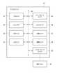
図4は、上述したプリンタユニット40の要部回路構成を示すブロック図である。プリンタユニット40は、操作パネル50に接続され、操作パネル50からのプリント要求に応じてレシートを発行する。 FIG. 4 is a block diagram showing a circuit configuration of a main part of the
プリンタユニット40は、プロセッサ81、メインメモリ82、印字ヘッド83、LEDランプ84、レシートロールセンサ85、ジャムセンサ86、収容センサ87、開閉センサ88、インタフェースユニット89、及び伝送路90等を備える。プロセッサ81、メインメモリ82、印字ヘッド83、LEDランプ84、レシートロールセンサ85、ジャムセンサ86、収容センサ87、開閉センサ88、およびインタフェースユニット89は、伝送路90を介して接続される。 The
プリンタユニット40においては、プロセッサ81及びメインメモリ82を伝送路90で接続することによって、プリンタユニット40を制御するための情報処理を行うコンピュータを構成する。なお、プリンタユニット40は、伝送路90に接続された補助記憶ユニットをさらに備え、この補助記憶ユニットを補助記憶部分として含んで上記のコンピュータが構成されてもよい。当該補助記憶ユニットとしては、例えばEEPROM(登録商標)(electric erasable programmable read-only memory)が用いられる。補助記憶ユニットとしては、HDD(hard disc drive)又はSSD(solid state drive)などを適用することもできる。 In the
プロセッサ81は、上記コンピュータの中枢部分に相当する。プロセッサ81は、オペレーティングシステム、ファームウェア及びアプリケーションプログラムに従って、プリンタユニット40としての各種の機能を実現するべく各部を制御する。 The
メインメモリ82は、上記コンピュータの主記憶部分に相当する。メインメモリ82は、不揮発性のメモリ領域と揮発性のメモリ領域とを含む。メインメモリ82は、不揮発性のメモリ領域ではオペレーティングシステム、ファームウェア及びアプリケーションプログラムを記憶する。またメインメモリ82は、プロセッサ81が各部を制御するための処理を実行する上で必要なデータを不揮発性又は揮発性のメモリ領域で記憶する場合もある。メインメモリ82は、揮発性のメモリ領域を、プロセッサ81によってデータが適宜書き換えられるワークエリアとして使用する。 The
印字ヘッド83は、プロセッサ81による指示の下に任意の画像や文字をレシートロールに対してプリントする。印字ヘッド83は、例えば、周知のサーマルヘッドである。印字ヘッド83は、プリンタユニット40の上部に設けたカバー46の内側に取り付けられている。つまり、印字ヘッド83は、プリンタユニット40とともに収容部12から引き出し可能となっている。このため、プリンタユニット40を収容部12から引き出した状態でもカバー46を閉じた状態であればレシート用紙への印字が可能である。 The print head 83 prints an arbitrary image or character on the receipt roll under the instruction of the
LEDランプ84は、オペレータに対し、プリンタユニット40の状態を知らせるための報知手段として機能する。LEDランプ84は、プリンタユニット40の前面41に設けられている。LEDランプ84は、プリンタユニット40が印字可能な状態にある場合に緑色で点灯するように制御され、プリンタユニット40が印字禁止状態である場合に赤色で点灯するように制御される。 The
レシートロールセンサ85は、プリンタユニット40内にレシートロールが正常に装着されていることを検出する。ジャムセンサ86は、プリンタユニット40においてレシート用紙のジャムが発生していることを検出する。レシートロールセンサ85及びジャムセンサ86は、プリンタユニット40の異常を検出する異常センサとして機能する。 The
収容センサ87は、プリンタユニット40の筐体10への収容状態を検出する。つまり、収容センサ87は、プリンタユニット40が装置100の収容部12内に正常に装着されていることを検出する。具体的には、収容センサ87は、プリンタユニット40が収容部12に装着されていることを検出するとともに、プリンタユニット40が装置100の筐体10から引き出された図2、3の状態であることを検出する。 The
開閉センサ88は、プリンタユニット40のカバー46の開閉状態を検出する。具体的には、開閉センサ88は、カバー46がプリンタユニット40の開口部44を塞ぐ閉位置に配置されていることを検出するとともに、カバー46が開口部44を全開にする図3に示す開位置に配置されていることを検出する。 The open /
カバー46は、プリンタユニット40を図2に示す位置に引き出した状態で図3に示すように開くことができる。言い換えると、カバー46は、プリンタユニット40を装置100の筐体10の収容部12内に収容した状態では開くことができない。 The
インタフェースユニット89には、操作パネル50が例えば通信ケーブルを介して接続される。インタフェースユニット89は、操作パネル50との間での各種データの送受信を行う。インタフェースユニット89としては、例えばUSB(universal serial bus)等の周知の規格に準拠した既製のデバイスを用いることができる。 An
伝送路90は、アドレスバス、データバス及び制御信号線等を含み、接続された各部の間で授受されるデータ及び制御信号を伝送する。 The
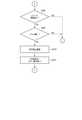
以下、上述したプリンタユニット40の第1の動作例について、図5を参照して説明する。 Hereinafter, the first operation example of the
プリンタユニット40が、操作パネル50からの要求に応じてレシートを発行することが可能な動作状態に設定されると、プロセッサ81は、メインメモリ82に記憶されたファームウェア又はアプリケーションプログラムに従って以下に説明する情報処理を実行する。 When the
Act1として、プロセッサ81は、レシート用紙切れであるか否かを判断する。レシート用紙切れであるか否かは、レシート用紙を搬送する経路にレシート用紙を検出するセンサを設け、このセンサの出力により判断する。或いは、プリンタユニット40内に収容配置したレシートロールのレシート用紙の残量を確認し、予め設定したしきい値と比較することで、レシート用紙切れであるか否かを判断してもよい。この場合、レシート用紙の残量は、例えば、新たなレシートロールに交換した後、装置100によるレシート発行枚数をカウントし、予め設定したレシートの平均長さとレシート発行枚数を乗算することで算出することができる。プロセッサ81は、Act1でレシート用紙切れを判断した場合(Act1;YES)、Act3へと進む。 As Act1, the
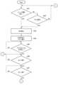
Act1でレシート用紙切れではないことを判断した場合(Act1;NO)、プロセッサ81は、Act2として、ジャムセンサ86を介してジャムの有無を検出して、プリンタユニット40にてレシート用紙のジャムが発生しているか否かを判断する。プロセッサ81は、Act2でジャムが発生していることを判断した場合(Act2;YES)、Act3へと進む。一方、Act2でジャムが発生していないことを判断した場合(Act2;NO)、プロセッサ81は、Act1に戻る。 When it is determined by Act1 that the receipt paper is not out (Act1; NO), the
Act3として、プロセッサ81は、まず、プリンタユニット40によるレシート用紙への印字を禁止する。次に、プロセッサ81は、Act4として、LEDランプ84を赤色で点灯させるとともに、操作画面51を介してエラー表示をするための信号を操作パネル50へ送信する。この際、エラー表示は、レシートロール切れやジャム発生をオペレータに報知する内容である。 As Act3, the
そして、プロセッサ81は、Act5として、レシートロールの交換或いはジャム処理のため、プリンタユニット40が筐体10の収容部12から引き出されたか否かを判断する。このとき、プロセッサ81は、収容センサ87を介して、プリンタユニット40が図2に図示した引き出し位置へ引き出された状態であるか否かを検出する。Act5でプリンタユニット40が引き出された状態であることを判断した場合(Act5;YES)、プロセッサ81は、Act6へ進む。 Then, the
Act6として、プロセッサ81は、開閉センサ88を介して、プリンタユニット40のカバー46が図3に示す状態に開かれたか否かを判断する。Act6でカバー46が開かれた状態であることを判断した後(Act6;YES)、Act7として、プロセッサ81は、開閉センサ88を介して、プリンタユニット40のカバー46が閉じられたか否かを判断する。Act7でカバー46が閉じられたことをプロセッサ81が判断するまで(Act7;NO)、すなわちカバー46が開かれている状態のとき、オペレータは、レシートロールの交換作業やジャム処理作業を実施する。 As Act6, the
Act7でカバー46が閉じられたことを判断すると(Act7;YES)、プロセッサ81は、Act8として、レシートロールセンサ85を介して、レシートロールがプリンタユニット40内の所定位置に正常に装着されているか否かを判断する。また、Act7でカバー46が閉じられたことを判断すると(Act7;YES)、プロセッサ81は、Act9として、ジャムセンサ86を介して、プリンタユニット40内でレシート用紙のジャムが無いことを確認する。 When it is determined by Act7 that the
そして、Act8でレシートロールが正常に装着されていることを判断し、且つAct9でジャムが無いことを判断した場合(Act8;YES、Act9;YES)、プロセッサ81は、Act10として、Act3で設定した印字禁止を解除してレシートロールへの印字を許可し、Act11へ進む。 Then, when it is determined in Act8 that the receipt roll is normally attached and there is no jam in Act9 (Act8; YES, Act9; YES), the
Act11として、プロセッサ81は、LEDランプ84を緑色で点灯させるとともに、操作画面51を介して表示していたエラー表示を終了するための信号を操作パネル50へ送信する。これにより、LEDランプ84が緑色で点灯する。 As
この状態で、プリンタユニット40は、図2に示す位置に引き出されたままであるが、レシートロールへの印字が可能な状態となり、レシートの発行が可能な状態となる。つまり、第1の動作例によると、プリンタユニット40がレシートを発行可能な状態で且つカバー46が閉じられた状態であれば、プリンタユニット40を引き出したままレシートの発行が可能であり、客にレシートを速やかに発行することができる。 In this state, the
また、第1の動作例によると、プリンタユニット40を引き出した状態でも、プリンタユニット40に異常が無い状態でカバー46が閉じられると、レシートの発行が可能であることを報知するLEDランプ84を緑色で点灯させる。このため、オペレータは、プリンタユニット40を収容部12へ収容する前にプリンタユニット40が正常に動作可能であることを判断することができ、レシートロールの交換作業やジャム処理作業の終了を速い段階で知ることができる。これにより、プリンタユニット40を収容部12へ押し込んでから動作確認する必要がなく、客に対してレシートを速やかに発行することができる。 Further, according to the first operation example, even when the
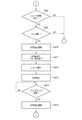
次に、プリンタユニット40の第2の動作例について、図7、8を参照して説明する。なお、Act1~Act11は上述した第1の動作例と略同じであるため、ここではその説明の大部分を省略する。
Next, a second operation example of the
第2の動作例では、プロセッサ81は、Act8でレシートロール有りを判断し且つAct9でジャム無しを判断した後、Act10として、Act3で設定した印字禁止を解除してレシートの発行を一枚だけ許可する。このとき、プロセッサ81は、Act3で印字禁止にする直前にスキャンした商品のコード情報に基づくレシートの発行を一枚だけ許可し、Act11へ進む。 In the second operation example, the
そして、プロセッサ81は、Act11として、LEDランプ84を緑色で点灯させるとともに、操作画面51を介して表示していたエラー表示を終了するための信号を操作パネル50へ送信し、Act12へ進む。Act12として、プロセッサ81は、レシートを一枚だけ発行し、Act13へ進む。 Then, the
この後、プロセッサ81は、Act13として、プリンタユニット40によるレシート用紙への印字を禁止し、Act14へ進む。そして、Act14として、プロセッサ81は、収容センサ87を介して、プリンタユニット40が収容部12へ収容されたか否かを判断し、プリンタユニット40が収容部12へ収容された場合(Act14;YES)に、Act15へ進む。 After that, the
最後に、Act15として、プロセッサ81は、Act13で設定した印字禁止状態を解除し、Act1へ戻る。 Finally, as Act 15, the
以上のように、第2の動作例によると、プリンタユニット40を引き出したままの状態で一枚だけレシートの発行を許可するようにしたため、レシートロールの交換作業或いはジャム処理作業の終了を待っている客に対してレシートを速やかに発行することができる。 As described above, according to the second operation example, since the issuance of only one receipt is permitted with the
また、第2の動作例によると、一度だけレシートを発行した後、プリンタユニット40を収容部12へ収容するまで、プリンタユニット40による印字を禁止するようにしたため、プリンタユニット40を引き出した状態のまま処理を続けることを防止することができる。 Further, according to the second operation example, after issuing the receipt only once, printing by the
以上述べた実施形態の商品データ処理装置によれば、プリンタユニット40におけるレシートロールの交換作業やジャム処理作業の後、プリンタユニット40を筐体10から引き出した状態のまま、レシートの発行が可能となる。このため、レシートロールの交換やジャム処理作業の終了後にレシートを速やかに発行することができ、利便性を向上させることができる。 According to the product data processing apparatus of the above-described embodiment, it is possible to issue a receipt while the
上述した実施形態は、例として提示したものであり、発明の範囲を限定することは意図していない。上述した実施形態は、その他の様々な形態で実施されることが可能であり、発明の要旨を逸脱しない範囲で、種々の省略、置き換え、変更を行うことができる。上述した実施形態やその変形は、発明の範囲や要旨に含まれると同様に、特許請求の範囲に記載された発明とその均等の範囲に含まれるものである。 The embodiments described above are presented as examples and are not intended to limit the scope of the invention. The above-described embodiment can be implemented in various other embodiments, and various omissions, replacements, and changes can be made without departing from the gist of the invention. The above-described embodiments and modifications thereof are included in the scope and gist of the invention, as well as in the scope of the invention described in the claims and the equivalent scope thereof.
例えば、上述した実施形態では、レシートの発行を許可したことをオペレータに知らせる報知手段としてLEDランプ84を用いた場合について説明したが、これに限らず、音声案内を発生させるスピーカを報知手段として用いても良い。
以下、本願の出願当初の特許請求の範囲に記載された発明を付記する。
[1]
プリンタユニットと、
前記プリンタユニットを引き出し可能に収容した筐体と、
前記プリンタユニットのカバーの開閉状態を検出する開閉センサと、
前記プリンタユニットを前記筐体から引き出した状態で前記開閉センサを介して前記カバーが閉じたことを検出した時点で、前記プリンタユニットによるレシートの発行が可能な場合に、前記プリンタユニットによるレシートの発行を許可する制御部と、
を有する商品データ処理装置。
[2]
前記制御部がレシートの発行を許可したことをオペレータに知らせる報知手段をさらに有する、
[1]の商品データ処理装置。
[3]
前記報知手段は、前記プリンタユニットに設けられている、
[2]の商品データ処理装置。
[4]
前記カバーは、前記プリンタユニットの上部に設けられ、レシートロールに印字する印字ヘッドを備えている、
[1]の商品データ処理装置。
[5]
前記制御部は、前記開閉センサを介して前記カバーが閉じたことを検出た時点で、前記プリンタユニットによるレシートの発行が可能な場合に、前記プリンタユニットによるレシートの発行を1度だけ許可し、その後、レシートの発行を禁止する、
[1]の商品データ処理装置。
[6]
プリンタユニットと、
前記プリンタユニットを引き出し可能に収容した筐体と、
前記プリンタユニットの前記筐体への収容状態を検出する収容センサと、
前記プリンタユニットのカバーの開閉状態を検出する開閉センサと、
前記プリンタユニットの異常を検出する異常センサと、
前記異常センサにより前記異常が検出されたことに応じて前記プリンタユニットによる印字を禁止し、前記収容センサにより前記プリンタユニットが前記筐体に収容されていないことが検出され、かつ前記開閉センサにより前記カバーが開いていることが検出された後、前記開閉センサにより前記カバーが閉じていることが検出され、かつ前記異常センサにより前記異常が検出されていない場合に、前記プリンタユニットによる印字を許可する制御部と、
を有する商品データ処理装置。
[7]
前記制御部は、印字を許可した後、1枚の印刷物の発行のための印字を前記プリンタユニットにより行ってから前記収容センサにより前記プリンタユニットが前記筐体に収容されていることが検出されるまで、前記プリンタユニットによる印字を禁止する、
[6]の商品データ処理装置。
For example, in the above-described embodiment, the case where the
Hereinafter, the inventions described in the scope of claims at the time of filing the application of the present application will be added.
[1]
Printer unit and
A housing in which the printer unit can be pulled out and a housing
An open / close sensor that detects the open / closed state of the cover of the printer unit, and
Issuing a receipt by the printer unit when it is possible to issue a receipt by the printer unit at the time when it is detected through the open / close sensor that the cover is closed with the printer unit pulled out from the housing. The control unit that allows
Commodity data processing equipment.
[2]
Further having a notification means for notifying the operator that the control unit has permitted the issuance of the receipt.
The product data processing device of [1].
[3]
The notification means is provided in the printer unit.
[2] Product data processing device.
[4]
The cover is provided on the upper part of the printer unit and includes a print head for printing on a receipt roll.
The product data processing device of [1].
[5]
When the control unit detects that the cover is closed via the open / close sensor, if the printer unit can issue a receipt, the control unit permits the printer unit to issue a receipt only once. After that, the issuance of receipts is prohibited,
The product data processing device of [1].
[6]
Printer unit and
A housing in which the printer unit can be pulled out and a housing
An accommodation sensor that detects the accommodation state of the printer unit in the housing, and
An open / close sensor that detects the open / closed state of the cover of the printer unit, and
An abnormality sensor that detects an abnormality in the printer unit and
Printing by the printer unit is prohibited in response to the detection of the abnormality by the abnormality sensor, the accommodation sensor detects that the printer unit is not accommodated in the housing, and the open / close sensor indicates that the printing is not performed. After the cover is detected to be open, if the open / close sensor detects that the cover is closed and the abnormality sensor does not detect the abnormality, printing by the printer unit is permitted. Control unit and
Commodity data processing equipment.
[7]
After permitting printing, the control unit performs printing for printing one printed matter by the printer unit, and then the accommodating sensor detects that the printer unit is accommodated in the housing. Until, printing by the printer unit is prohibited.
[6] Product data processing device.
10…筐体、11…前面、12…収容部、30…スキャナユニット、40…プリンタユニット、42…排出口、43…レール、44…開口部、46…カバー、50…操作パネル、51…操作画面、81…プロセッサ、82…メインメモリ、83…印字ヘッド、84…LEDランプ、85…レシートロールセンサ、86…ジャムセンサ、87…収容センサ、88…開閉センサ、89…インタフェースユニット、90…伝送路、100…商品データ処理装置、S…作業スペース。 10 ... Housing, 11 ... Front, 12 ... Storage, 30 ... Scanner unit, 40 ... Printer unit, 42 ... Discharge port, 43 ... Rail, 44 ... Opening, 46 ... Cover, 50 ... Operation panel, 51 ... Operation Screen, 81 ... Processor, 82 ... Main memory, 83 ... Print head, 84 ... LED lamp, 85 ... Receipt roll sensor, 86 ... Jam sensor, 87 ... Accommodation sensor, 88 ... Open / close sensor, 89 ... Interface unit, 90 ... Transmission Road, 100 ... Product data processing device, S ... Work space.
Claims (7)
Translated fromJapanese前記プリンタユニットを引き出し可能に収容した筐体と、
前記プリンタユニットのカバーの開閉状態を検出する開閉センサと、
前記プリンタユニットを前記筐体から引き出した状態で前記開閉センサを介して前記カバーが閉じたことを検出した時点で、前記プリンタユニットによるレシートの発行が可能な場合に、前記プリンタユニットを前記筐体から引き出した状態での前記プリンタユニットによるレシートの発行を許可する制御部と、
を有する商品データ処理装置。Printer unit and
A housing in which the printer unit can be pulled out and a housing
An open / close sensor that detects the open / closed state of the cover of the printer unit, and
When it is detected that the cover is closed via the open / close sensor with the printer unit pulled out from the housing, if the printer unit can issue a receipt, the printer unit is mounted on thehousing. A control unit that allows the printer unit to issue a receiptwhen it is pulled out from the printer unit.
Commodity data processing equipment.
請求項1の商品データ処理装置。Further having a notification means for notifying the operator that the control unit has permitted the issuance of the receipt.
The product data processing device according to claim 1.
請求項2の商品データ処理装置。The notification means is provided in the printer unit.
The product data processing device according to claim 2.
請求項1の商品データ処理装置。The cover is provided on the upper part of the printer unit and includes a print head for printing on a receipt roll.
The product data processing device according to claim 1.
請求項1の商品データ処理装置。When the control unit detects that the cover is closed via the open / close sensor, if the printer unit can issue a receipt, the control unit permits the printer unit to issue a receipt only once. After that, the issuance of receipts is prohibited,
The product data processing device according to claim 1.
前記プリンタユニットを引き出し可能に収容した筐体と、
前記プリンタユニットの前記筐体への収容状態を検出する収容センサと、
前記プリンタユニットのカバーの開閉状態を検出する開閉センサと、
前記プリンタユニットの異常を検出する異常センサと、
前記異常センサにより前記異常が検出されたことに応じて前記プリンタユニットによる印字を禁止し、前記収容センサにより前記プリンタユニットが前記筐体に収容されていないことが検出され、かつ前記開閉センサにより前記カバーが開いていることが検出された後、前記開閉センサにより前記カバーが閉じていることが検出され、かつ前記異常センサにより前記異常が検出されていない場合に、前記プリンタユニットを前記筐体から引き出した状態での前記プリンタユニットによる印字を許可する制御部と、
を有する商品データ処理装置。Printer unit and
A housing in which the printer unit can be pulled out and a housing
An accommodation sensor that detects the accommodation state of the printer unit in the housing, and
An open / close sensor that detects the open / closed state of the cover of the printer unit, and
An abnormality sensor that detects an abnormality in the printer unit and
Printing by the printer unit is prohibited in response to the detection of the abnormality by the abnormality sensor, the accommodation sensor detects that the printer unit is not accommodated in the housing, and the open / close sensor indicates that the printing is not performed. After it is detected that the cover is open, when the open / close sensor detects that the cover is closed and the abnormality sensor does not detect the abnormality, theprinter unit is removed from the housing. A control unit that allows printing by the printer unitin the pulled out state, and
Commodity data processing equipment.
請求項6の商品データ処理装置。
After permitting printing, the control unit performs printing for printing one printed matter by the printer unit, and then the accommodation sensor detects that the printer unit is accommodated in the housing. Until then, printing by the printer unit is prohibited.
The product data processing device according to claim 6.
Priority Applications (8)
| Application Number | Priority Date | Filing Date | Title |
|---|---|---|---|
| JP2018030602AJP7005379B2 (en) | 2018-02-23 | 2018-02-23 | Product data processing device |
| CN202111385548.9ACN114067503B (en) | 2018-02-23 | 2019-01-28 | Commodity data processing device and control method |
| CN201910081420.XACN110189487B (en) | 2018-02-23 | 2019-01-28 | Product data processing device and control method |
| US16/280,437US11142010B2 (en) | 2018-02-23 | 2019-02-20 | Commodity-data processing apparatus |
| EP19158619.7AEP3531383B1 (en) | 2018-02-23 | 2019-02-21 | Commodity-data processing apparatus |
| US17/498,969US11904617B2 (en) | 2018-02-23 | 2021-10-12 | Commodity-data processing apparatus |
| JP2022000599AJP7303337B2 (en) | 2018-02-23 | 2022-01-05 | Product data processor |
| JP2023102417AJP7540045B2 (en) | 2018-02-23 | 2023-06-22 | Product data processing device |
Applications Claiming Priority (1)
| Application Number | Priority Date | Filing Date | Title |
|---|---|---|---|
| JP2018030602AJP7005379B2 (en) | 2018-02-23 | 2018-02-23 | Product data processing device |
Related Child Applications (1)
| Application Number | Title | Priority Date | Filing Date |
|---|---|---|---|
| JP2022000599ADivisionJP7303337B2 (en) | 2018-02-23 | 2022-01-05 | Product data processor |
Publications (2)
| Publication Number | Publication Date |
|---|---|
| JP2019144993A JP2019144993A (en) | 2019-08-29 |
| JP7005379B2true JP7005379B2 (en) | 2022-01-21 |
Family
ID=65657220
Family Applications (1)
| Application Number | Title | Priority Date | Filing Date |
|---|---|---|---|
| JP2018030602AActiveJP7005379B2 (en) | 2018-02-23 | 2018-02-23 | Product data processing device |
Country Status (4)
| Country | Link |
|---|---|
| US (2) | US11142010B2 (en) |
| EP (1) | EP3531383B1 (en) |
| JP (1) | JP7005379B2 (en) |
| CN (2) | CN114067503B (en) |
Families Citing this family (2)
| Publication number | Priority date | Publication date | Assignee | Title |
|---|---|---|---|---|
| JP6760618B1 (en) | 2019-07-17 | 2020-09-23 | Necプラットフォームズ株式会社 | POS terminal device |
| US11430096B2 (en)* | 2020-04-10 | 2022-08-30 | Ncr Corporation | Detecting and preventing receipt printer jams |
Citations (5)
| Publication number | Priority date | Publication date | Assignee | Title |
|---|---|---|---|---|
| JP2002160411A (en) | 2000-11-22 | 2002-06-04 | Seiko Epson Corp | Printer |
| JP2003091776A (en) | 2001-09-19 | 2003-03-28 | Sharp Corp | Electronic cash register |
| JP2004209862A (en) | 2003-01-07 | 2004-07-29 | Ricoh Co Ltd | Image forming apparatus, program, and recording medium |
| JP2009276973A (en) | 2008-05-14 | 2009-11-26 | Seiko Epson Corp | Printer, pos system, control method for printer and program |
| JP2010009492A (en) | 2008-06-30 | 2010-01-14 | Toshiba Tec Corp | Ticket issuing system |
Family Cites Families (32)
| Publication number | Priority date | Publication date | Assignee | Title |
|---|---|---|---|---|
| JPH0652442A (en)* | 1992-07-30 | 1994-02-25 | Tokyo Electric Co Ltd | Article sales data processor |
| US6065679A (en)* | 1996-09-06 | 2000-05-23 | Ivi Checkmate Inc. | Modular transaction terminal |
| US6042007A (en) | 1998-10-16 | 2000-03-28 | Ncr Corporation | Self-service computer assembly with integrated receipt printer |
| JP2004090443A (en)* | 2002-08-30 | 2004-03-25 | Seiko Epson Corp | Printer, method of outputting status information in printer, program for executing the method, computer-readable recording medium on which the program is recorded, and printer system |
| CN1286657C (en) | 2003-04-15 | 2006-11-29 | 精工爱普生株式会社 | Printer |
| JP3797622B2 (en)* | 2004-01-28 | 2006-07-19 | 東芝テック株式会社 | Payment terminal |
| US7986420B2 (en)* | 2006-11-29 | 2011-07-26 | International Business Machines Corporation | Sensing paper jam, out-of-paper, and cover open in a printer |
| GR1006823B (en)* | 2007-01-30 | 2010-07-01 | Ιντραλοτ Ανωνυμη Εταιρεια Ολοκληρωμενα Πληροφοριακα Συστηματα Και Υπηρεσιες Τυχερων Παιχνιδιων, | Small-sized lottery terminal |
| US20080182639A1 (en)* | 2007-01-30 | 2008-07-31 | Konstantinos Antonopoulos | Lottery terminal |
| JP5298954B2 (en)* | 2008-04-10 | 2013-09-25 | セイコーエプソン株式会社 | Printer recording paper transport control method and printer |
| JP5057098B2 (en) | 2008-10-29 | 2012-10-24 | Necインフロンティア株式会社 | Printer roll paper set structure |
| JP4773535B2 (en)* | 2009-02-13 | 2011-09-14 | 東芝テック株式会社 | Product sales data processing device |
| JP2011107774A (en)* | 2009-11-12 | 2011-06-02 | Toshiba Tec Corp | Commodity sales data processor and control program therefor |
| US8321052B2 (en)* | 2009-11-27 | 2012-11-27 | Ncr Corporation | Self-service kiosk with multiple secure service areas |
| BRPI1005607B1 (en)* | 2009-12-17 | 2021-02-23 | Seiko Epson Corporation | electronic device and method to control electronic device |
| WO2011131154A1 (en)* | 2010-04-21 | 2011-10-27 | Leung Yim Mui | Wireless cash register |
| CN101905578B (en)* | 2010-07-19 | 2012-07-11 | 山东新北洋信息技术股份有限公司 | Printer and control method thereof |
| JP5578978B2 (en)* | 2010-07-30 | 2014-08-27 | 光雄 沼尻 | Reception device |
| JP2013107258A (en) | 2011-11-21 | 2013-06-06 | Sinfonia Technology Co Ltd | Printer |
| CN202480556U (en)* | 2012-03-05 | 2012-10-10 | 毛大庆 | Miniprinter capable of popping up by pressing to change paper |
| JP6191310B2 (en)* | 2013-07-25 | 2017-09-06 | 株式会社寺岡精工 | Printing apparatus and sales data processing apparatus having the printing apparatus |
| JP5663070B2 (en) | 2013-10-04 | 2015-02-04 | Necプラットフォームズ株式会社 | Self POS system |
| JP6251154B2 (en) | 2014-11-11 | 2017-12-20 | 東芝テック株式会社 | Docking station and its control program |
| JP2016162147A (en)* | 2015-02-27 | 2016-09-05 | スター精密株式会社 | Printer/drawer-integrated type device and pos system |
| US9600026B2 (en)* | 2015-07-14 | 2017-03-21 | Zivelo Inc. | Interactive kiosk systems and methods for their manufacture |
| JP6704758B2 (en)* | 2016-03-07 | 2020-06-03 | 東芝テック株式会社 | Accounting equipment |
| JP2017228140A (en)* | 2016-06-23 | 2017-12-28 | 東芝テック株式会社 | Reading apparatus and program |
| JP2017228139A (en)* | 2016-06-23 | 2017-12-28 | 東芝テック株式会社 | POS device |
| CN206287667U (en)* | 2016-10-08 | 2017-06-30 | 南京凤源新材料科技有限公司 | A kind of built-in automation print system |
| CN206431427U (en)* | 2017-01-23 | 2017-08-22 | 天津科兴伟创科技有限公司 | A kind of high-definition laser printer |
| CN206921240U (en)* | 2017-06-23 | 2018-01-23 | 客如云科技(深圳)有限责任公司 | A kind of intelligent supermarket cash register |
| CN206819482U (en)* | 2017-07-06 | 2017-12-29 | 蒋亚利 | A kind of intelligent financial POS machine device |
- 2018
- 2018-02-23JPJP2018030602Apatent/JP7005379B2/enactiveActive
- 2019
- 2019-01-28CNCN202111385548.9Apatent/CN114067503B/enactiveActive
- 2019-01-28CNCN201910081420.XApatent/CN110189487B/enactiveActive
- 2019-02-20USUS16/280,437patent/US11142010B2/enactiveActive
- 2019-02-21EPEP19158619.7Apatent/EP3531383B1/enactiveActive
- 2021
- 2021-10-12USUS17/498,969patent/US11904617B2/enactiveActive
Patent Citations (5)
| Publication number | Priority date | Publication date | Assignee | Title |
|---|---|---|---|---|
| JP2002160411A (en) | 2000-11-22 | 2002-06-04 | Seiko Epson Corp | Printer |
| JP2003091776A (en) | 2001-09-19 | 2003-03-28 | Sharp Corp | Electronic cash register |
| JP2004209862A (en) | 2003-01-07 | 2004-07-29 | Ricoh Co Ltd | Image forming apparatus, program, and recording medium |
| JP2009276973A (en) | 2008-05-14 | 2009-11-26 | Seiko Epson Corp | Printer, pos system, control method for printer and program |
| JP2010009492A (en) | 2008-06-30 | 2010-01-14 | Toshiba Tec Corp | Ticket issuing system |
Also Published As
| Publication number | Publication date |
|---|---|
| US11904617B2 (en) | 2024-02-20 |
| US11142010B2 (en) | 2021-10-12 |
| EP3531383B1 (en) | 2023-04-19 |
| CN110189487B (en) | 2021-12-14 |
| US20190263161A1 (en) | 2019-08-29 |
| EP3531383A1 (en) | 2019-08-28 |
| CN114067503B (en) | 2024-06-07 |
| CN110189487A (en) | 2019-08-30 |
| US20220024235A1 (en) | 2022-01-27 |
| CN114067503A (en) | 2022-02-18 |
| JP2019144993A (en) | 2019-08-29 |
Similar Documents
| Publication | Publication Date | Title |
|---|---|---|
| JP6266499B2 (en) | Product sales data processing device | |
| US11904617B2 (en) | Commodity-data processing apparatus | |
| US20200035070A1 (en) | Registration settlement apparatus | |
| US20210042729A1 (en) | Commodity registration apparatus, checkout apparatus, and information processing method | |
| JP2019096035A (en) | Settlement device, registration settlement device and information processing program | |
| JP6158717B2 (en) | Coin receiving apparatus, settlement processing apparatus, and control program for settlement processing apparatus | |
| JP6266500B2 (en) | Merchandise sales data processing apparatus and control program thereof | |
| CN107818642A (en) | Checkout system, checkout apparatus and its control method, server | |
| JP7170445B2 (en) | Registered payment device and information processing program | |
| JP7303337B2 (en) | Product data processor | |
| JP2021073626A (en) | Money collection device and control program | |
| JP2023103475A (en) | Registration settlement device | |
| US10607205B2 (en) | Settlement apparatus, control program therefor, and checkout system | |
| JP7081001B2 (en) | Information processing equipment and its programs | |
| JP2020138550A (en) | Printers, recording media and sales data processing equipment | |
| JP7334321B2 (en) | Registration device and information processing program | |
| JP7149359B2 (en) | Automatic change machine and control program | |
| JP7304745B2 (en) | self checkout device | |
| JP7200201B2 (en) | Payment device and its control program | |
| JP6843205B2 (en) | Automatic change machine and payment processing device | |
| JP6914685B2 (en) | Coin payout device, payment device and its program | |
| JP2022168236A (en) | Registration devices, checkout systems and accounting devices | |
| JP2023115159A (en) | Settlement device, registration settlement device and information processing program | |
| JP2017152058A (en) | Settlement processing apparatus and control program of settlement processing apparatus |
Legal Events
| Date | Code | Title | Description |
|---|---|---|---|
| A621 | Written request for application examination | Free format text:JAPANESE INTERMEDIATE CODE: A621 Effective date:20201008 | |
| A977 | Report on retrieval | Free format text:JAPANESE INTERMEDIATE CODE: A971007 Effective date:20210825 | |
| A131 | Notification of reasons for refusal | Free format text:JAPANESE INTERMEDIATE CODE: A131 Effective date:20210831 | |
| A521 | Request for written amendment filed | Free format text:JAPANESE INTERMEDIATE CODE: A523 Effective date:20211026 | |
| TRDD | Decision of grant or rejection written | ||
| A01 | Written decision to grant a patent or to grant a registration (utility model) | Free format text:JAPANESE INTERMEDIATE CODE: A01 Effective date:20211207 | |
| A61 | First payment of annual fees (during grant procedure) | Free format text:JAPANESE INTERMEDIATE CODE: A61 Effective date:20220105 | |
| R150 | Certificate of patent or registration of utility model | Ref document number:7005379 Country of ref document:JP Free format text:JAPANESE INTERMEDIATE CODE: R150 |