JP7005253B2 - Image forming device - Google Patents
Image forming deviceDownload PDFInfo
- Publication number
- JP7005253B2 JP7005253B2JP2017188362AJP2017188362AJP7005253B2JP 7005253 B2JP7005253 B2JP 7005253B2JP 2017188362 AJP2017188362 AJP 2017188362AJP 2017188362 AJP2017188362 AJP 2017188362AJP 7005253 B2JP7005253 B2JP 7005253B2
- Authority
- JP
- Japan
- Prior art keywords
- toner
- image forming
- storage container
- image
- bottle
- Prior art date
- Legal status (The legal status is an assumption and is not a legal conclusion. Google has not performed a legal analysis and makes no representation as to the accuracy of the status listed.)
- Active
Links
Images


Classifications
- G—PHYSICS
- G03—PHOTOGRAPHY; CINEMATOGRAPHY; ANALOGOUS TECHNIQUES USING WAVES OTHER THAN OPTICAL WAVES; ELECTROGRAPHY; HOLOGRAPHY
- G03G—ELECTROGRAPHY; ELECTROPHOTOGRAPHY; MAGNETOGRAPHY
- G03G15/00—Apparatus for electrographic processes using a charge pattern
- G03G15/06—Apparatus for electrographic processes using a charge pattern for developing
- G03G15/08—Apparatus for electrographic processes using a charge pattern for developing using a solid developer, e.g. powder developer
- G03G15/0822—Arrangements for preparing, mixing, supplying or dispensing developer
- G03G15/0865—Arrangements for supplying new developer
- G—PHYSICS
- G03—PHOTOGRAPHY; CINEMATOGRAPHY; ANALOGOUS TECHNIQUES USING WAVES OTHER THAN OPTICAL WAVES; ELECTROGRAPHY; HOLOGRAPHY
- G03G—ELECTROGRAPHY; ELECTROPHOTOGRAPHY; MAGNETOGRAPHY
- G03G15/00—Apparatus for electrographic processes using a charge pattern
- G03G15/50—Machine control of apparatus for electrographic processes using a charge pattern, e.g. regulating differents parts of the machine, multimode copiers, microprocessor control
- G03G15/5016—User-machine interface; Display panels; Control console
- G—PHYSICS
- G03—PHOTOGRAPHY; CINEMATOGRAPHY; ANALOGOUS TECHNIQUES USING WAVES OTHER THAN OPTICAL WAVES; ELECTROGRAPHY; HOLOGRAPHY
- G03G—ELECTROGRAPHY; ELECTROPHOTOGRAPHY; MAGNETOGRAPHY
- G03G15/00—Apparatus for electrographic processes using a charge pattern
- G03G15/60—Apparatus which relate to the handling of originals
- G03G15/602—Apparatus which relate to the handling of originals for transporting
Landscapes
- Physics & Mathematics (AREA)
- General Physics & Mathematics (AREA)
- Engineering & Computer Science (AREA)
- Microelectronics & Electronic Packaging (AREA)
- Dry Development In Electrophotography (AREA)
- Control Or Security For Electrophotography (AREA)
Description
Translated fromJapanese本発明は、現像剤を収容した収容容器が着脱可能な画像形成装置に関する。The present invention relates to an image formingapparatus in which a container containing a developer can be attached and detached.
電子写真方式の画像形成装置は、感光体上に形成された静電潜像を、現像器内の現像剤を用いて現像することによって画像を形成する。現像器内に蓄積できる現像剤の量には限りがあるので、画像形成装置に着脱可能な収容容器から現像器へ適宜現像剤が補給される。なお、収容容器内の現像剤の量にも限りがあるので、収容容器内に現像剤がなくなると、収容容器から現像器へ現像剤が補給できなくなる。 The electrophotographic image forming apparatus forms an image by developing an electrostatic latent image formed on a photoconductor using a developer in a developing device. Since the amount of the developer that can be stored in the developer is limited, the developer is appropriately replenished from the container that can be attached to and detached from the image forming apparatus to the developer. Since the amount of the developer in the container is limited, when the developer runs out in the container, the developer cannot be replenished from the container to the developer.
また、収容容器が取り外された状態であっても画像形成動作を維持できる画像形成装置も知られている。つまり、ユーザは画像形成動作が中断されることなく収容容器を交換できる。 Further, an image forming apparatus capable of maintaining an image forming operation even when the storage container is removed is also known. That is, the user can replace the storage container without interrupting the image forming operation.
ここで、収容容器内の現像剤の量が所定量以上であるにも拘わらず、ユーザが収容容器を交換してしまうことがある。そこで、特許文献1に記載の画像形成装置は、収容容器が空となる前に収容容器が取り出された場合に、画像形成動作の実行を禁止している。特許文献1に記載の画像形成装置によれば、空ではない収容容器が再装着されることで画像形成動作が実行できるので、現像剤が残っている収容容器が廃棄されることを抑制できる。 Here, even though the amount of the developer in the storage container is equal to or more than a predetermined amount, the user may replace the storage container. Therefore, the image forming apparatus described in Patent Document 1 prohibits the execution of the image forming operation when the containing container is taken out before the containing container is emptied. According to the image forming apparatus described in Patent Document 1, since the image forming operation can be executed by reattaching the non-empty accommodating container, it is possible to prevent the accommodating container in which the developer remains from being discarded.
しかしながら、特許文献1の画像形成装置では、画像形成動作中に、空となる前のトナーボトルを取り外して別のトナーボトルに交換した場合に、画像形成装置の内部にシートが残留した状態で装置が停止する可能性がある。シートが装置内に残ってしまうと、ユーザには、元のトナーボトルに戻す作業に加え、内部に残ったシートの除去作業が生じ、煩雑である。 However, in the image forming apparatus of Patent Document 1, when the toner bottle before it is emptied is removed and replaced with another toner bottle during the image forming operation, the sheet remains inside the image forming apparatus. May stop. If the sheet remains in the device, the user needs to remove the sheet remaining inside in addition to the work of returning the toner bottle to the original one, which is complicated.
本発明の目的は、空ではないトナーボトルが他のトナーボトルに交換された場合であっても、画像形成装置の内部にシートが残存することを抑制することにある。 An object of the present invention is to prevent the sheet from remaining inside the image forming apparatus even when a non-empty toner bottle is replaced with another toner bottle.
上記目的を達成するために本発明は、搬送路に沿ってシートを搬送する搬送手段と、現像剤を蓄積する現像器を有し、前記現像器の現像剤を用いて、前記搬送手段により搬送された前記シートに画像を形成する画像形成手段と、前記現像器に補給するための現像剤を収容した収容容器が装着される装着部と、前記装着部に装着された収容容器から前記現像器へ現像剤を補給する補給手段と、前記装着部に装着された収容容器が交換条件を満たしていない状態で他の収容容器へ交換された場合、前記画像形成手段が前記搬送路に残ったシートへ画像を形成し終えた後に前記画像形成手段による画像形成を停止する停止手段と、前記装着された収容容器が前記交換条件を満たしていない状態で他の収容容器へ交換された場合、前記交換条件を満たしていない収容容器の再装着を促すための報知を実施する報知手段と、を有し、前記停止手段は、画像形成ジョブの投入後に、前記報知手段による報知が実施されているか否かを判定し、前記報知が実施されている場合に、前記画像形成手段による画像形成を停止することを特徴とする。In order to achieve the above object, the present invention has a transport means for transporting a sheet along a transport path and a developer for accumulating a developer, and the developer of the developer is used to transport the sheet by the transport means. An image forming means for forming an image on the sheet, a mounting portion on which a storage container containing a developer for supplying to the developing device is mounted, and a developing unit from a storage container mounted on the mounting portion. When the replenishment means for replenishing the developing agent and the storage container mounted on the mounting portion are replaced with another storage container in a state where the replacement conditions are not satisfied, the image forming means remains in the transport path. When the stop means for stopping the image formation by the image forming means after the image formation is completed andthe mounted storage container is replaced with another storage container in a state where the exchange conditions are not satisfied, the exchange is performed. It has a notification means for prompting the reattachment of a storage container that does not satisfy the conditions, and the stop means has whether or not the notification by the notification means is executed after the image forming job is input. Is determined, and when the notification is performed, the image formation by the image forming means is stopped .
本発明によれば、空ではないトナーボトルが他のトナーボトルに交換された場合であっても、画像形成装置の内部にシートが残存することを抑制できる。 According to the present invention, even when a non-empty toner bottle is replaced with another toner bottle, it is possible to prevent the sheet from remaining inside the image forming apparatus.
以下、図面を参照して本発明の実施の形態を説明する。 Hereinafter, embodiments of the present invention will be described with reference to the drawings.
(第1の実施の形態)
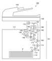
図1は、本発明の第1の実施の形態に係る画像形成装置の構成を示す概略断面図である。この画像形成装置100は、シートへの画像形成を行うプリンタ101と、原稿の画像の読み取りを行うリーダ102と、読み取り対象となる原稿の搬送を行うADFユニット103とを備える。(First Embodiment)
FIG. 1 is a schematic cross-sectional view showing the configuration of an image forming apparatus according to the first embodiment of the present invention. The
プリンタ101では、給紙カセット110に収納されたシートPが、ピックアップローラ111、給紙ローラ112及びリタードローラ113によって1枚ずつ給紙される。給紙カセット110から給紙されたシートPは、搬送手段としての搬送ローラ114によって搬送路116に沿って搬送される。シートPは、レジストローラ対115の位置に達すると、停止しているレジストローラ対115によって斜行補正が行われる。その後、レジストローラ対115の回転が開始されることで、シートPは、感光ドラム131と転写ローラ133との間の転写ニップ部へ搬送される。 In the
プリンタ101は、レーザスキャナ120、感光ドラム131、帯電ローラ132、転写ローラ133、及び現像器140を備える。これらが、シートに画像を形成する画像形成手段の主要部を構成する。プリンタ101は、シートPへ画像を形成する。プリンタ101では、回転駆動される感光ドラム131の外周面が、帯電ローラ132の作用によって所定の極性の電位に一様に帯電する。レーザスキャナ120は、帯電した感光ドラム131を光ビーム(レーザ光)によって露光する。具体的には、レーザスキャナ120は、画像情報(時系列のデジタル画素信号)に応じて変調されたレーザ光Lを出力し、帯電した感光ドラム131をレーザ光Lで走査することで、感光ドラム131上に静電潜像を形成する。なお、レーザスキャナ120は、リーダ102によって原稿の画像を読み取って得られた画像データ(画像情報)、またはPC等の外部装置からネットワークを介して受信した画像データに基づいて、レーザ光Lを出力する。 The
現像器140は現像剤を蓄積する。トナー補給部150には、現像剤(トナー)が収容された収容容器であるトナーボトルTが着脱可能である。トナー補給部150はトナーボトルTが装着される装着部として機能する。現像器140は、現像ローラ141を含み、トナー補給部150から供給(補給)されるトナーを用いて感光ドラム131上の静電潜像を現像してトナー画像を形成する。そのため、画像データに応じたトナーが現像器140から排出される。感光ドラム131上に形成されたトナー画像は、感光ドラム131の回転に伴って転写ニップ部へ移動する。感光ドラム131と逆極性の転写バイアスが転写ローラ133に印加されており、感光ドラム131上のトナー画像は転写ニップ部においてシートPの表面に転写される。 The
プリンタ101においてトナー画像が転写されたシートPは、定着器160内へ搬送される。定着器160は、定着ヒータ及び加圧ローラによって熱及び圧力をシートPに加えることで、シートP上のトナー画像をシートPに定着させる。このようにして画像が形成されたシートPは、定着器160の通過後、排紙ローラ170によって装置外部の排紙トレイ171へ排紙(排出)される。 The sheet P to which the toner image is transferred in the
また、シートPへ両面印刷が行われる場合には、第1面に対する画像形成が終了したシートPは、反転フラッパ181の位置を通過後、排紙ローラ170によって逆方向に搬送され、反転フラッパ181によって反転搬送路180へ導かれる。反転搬送路180に導かれたシートPは、搬送ローラ182、183によって、再びレジストローラ対115の位置へ搬送される。その際、シートPは、第1面に対する画像形成の際と比較して、第1面と第2面とが反転した状態となっている。その後、シートPは、第1面に対する上述の画像形成と同様に、第2面に対する画像形成が行われた後、排紙トレイ171へ排出される。 When double-sided printing is performed on the sheet P, the sheet P for which the image formation on the first surface is completed passes through the position of the
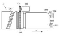
図2は、画像形成装置100のトナー補給部150に装着されたトナーボトルTの外観図である。トナーボトルTは、キャップ部222、トナーを収容する収容部207、ボトルモータ201からの回転駆動力が伝達される駆動伝達部206、トナーを排出する排出口(不図示)を備える。キャップ部222は、トナーボトルTの装着方向(矢印M方向)の奥側に突起222aを有する。画像形成装置100に設けられている検知手段としてのボトルセンサ203は、キャップ部222の突起222aを検出することに応じて、トナーボトルTが装着されていることを示す信号を出力する。また、キャップ部222には、トナーボトルTに関する情報を記録したメモリ223が貼り付けられている。 FIG. 2 is an external view of the toner bottle T attached to the
図3は、画像形成装置100におけるトナー補給部150の構成を示す概略図である。トナー補給部150には、トナーが予め充填されたトナーボトルTがユーザによって設置される。トナー補給部150は、トナーボトルT、ボトルモータ201、トナー搬送路210及び搬送路モータ211を備えている。トナー搬送路210は、トナーボトルTから排出されたトナーを一時的に蓄積するバッファ部として機能する。トナー搬送路210は、現像器140の一部である。 FIG. 3 is a schematic view showing the configuration of the
トナーボトルTの駆動伝達部206(図2)は、駆動ギア列214を介してボトルモータ201と接続されており、ボトルモータ201から駆動伝達部206に回転駆動力が与えられる。ボトルモータ201が回転することで、トナーボトルTは矢印A方向に回転する。トナーボトルTが回転することで、トナーボトルTの内部からトナーが排出されてトナー搬送路210内へ流入する。トナー搬送路210内にはスクリュー212が設けられている。スクリュー212の回転軸は、駆動ギア列(不図示)を介して搬送路モータ211と接続されており、搬送路モータ211から駆動ギア列を介してスクリュー212の回転軸に回転駆動力が与えられる。スクリュー212は、回転することで、トナー搬送路210内に流入したトナーを一方向(図3において左から右)へ搬送する。トナー搬送路210を通じて搬送されたトナーは、トナー搬送路210の端部において現像器140へ補給される。ボトルモータ201及び搬送路モータ211が、本発明における補給手段に該当する。 The drive transmission unit 206 (FIG. 2) of the toner bottle T is connected to the
トナー補給部150は、ボトルホームポジションセンサであるHPセンサ202、及び第2のセンサである第2のトナーセンサ213を備えている。HPセンサ202は、トナーボトルTの回転の基準となる位置(ホームポジション)を検知するためのセンサであり、トナーボトルTの回転制御に用いられる。第2のトナーセンサ213は、トナー搬送路210内に配置される。また、現像器140の内部には、現像器140内のトナーの有無を検知するための第1のセンサである第1のトナーセンサ221が備えられている。 The
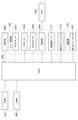
図4は、画像形成装置100の制御ブロック図である。画像形成装置100は、CPU400、ROM401、RAM402を備えている。ROM401には、画像形成装置100全体を制御するための制御プログラムが格納されている。RAM402は、揮発性の記憶デバイスであり、CPU400の作業領域として使用されるとともに、画像データ等の種々のデータを一時的に格納するために使用される。CPU400は、ROM401に格納された制御プログラムをRAM402に読み出して実行することによって、画像形成装置100全体を制御する。 FIG. 4 is a control block diagram of the
CPU400は、ボトルモータ201及び搬送路モータ211の動作を制御することで、トナー補給部150の動作を制御する。CPU400には、トナー補給部150のHPセンサ202、ボトルセンサ203及び第2のトナーセンサ213からそれぞれ出力される信号、及び現像器140の第1のトナーセンサ221から出力される信号が入力される。 The
読取部204(図2)は、画像形成装置100における装着位置に装着されたトナーボトルTのメモリ223に記録された「補給情報」を読み取ってCPU400へ通知する取得手段である。さらに読取部204は、CPU400から通知された補給情報をトナーボトルTのメモリ223へ書き込むこともできる。上記補給情報は、例えば、トナーボトルTの製造番号、トナーボトルTによる補給履歴、トナーボトルT内のトナーが「空」であるか否かの判定結果を示す情報を含む。トナーボトルTの製造番号は、トナーボトルT毎に割り振られており、トナーボトルTの各々を一意に特定するための識別情報となる。CPU400は、製造番号によりトナーボトルTの各々を識別する。なお、トナーボトルTによる補給履歴は例えば、トナーボトルTの回転回数である。CPU400は、トナーボトルTを1回転させる度に、読取部204によってトナーボトルTの回転回数の情報をメモリ223に記録する。トナーボトルTの回転回数はトナーボトルTからの補給回数に対応する。 The reading unit 204 (FIG. 2) is an acquisition means for reading "replenishment information" recorded in the
操作部300は表示部としてのタッチパネル(画面)を有する。操作部300のタッチパネルは、CPU400からの信号によって、ホーム画面、交換画面、警告画面等を表示する。さらに、タッチパネルはCPU400からの信号によって画像形成装置100の状態をユーザに通知する。なお、前述の画面を表示する構成はタッチパネルに限らず、例えば、ネットワークを通じて画像形成装置100と通信可能に接続されたPCのモニタであってもよい。 The
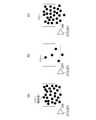
次に、第1のトナーセンサ221、第2のトナーセンサ213による、トナーの有無検知処理について図5で説明する。図5(a)、(b)、(c)は、移動しているトナーをトナーセンサ221、213が検知する様子を示す図である。トナー搬送路210内に設けられた第2のトナーセンサ213、及び現像器140内に設けられた第1のトナーセンサ221はいずれも透磁率センサである。そして、図5(a)、図5(c)に示すように、トナーセンサ221、213は、磁性体を含むトナーを検知した場合にはON(オン)状態の信号を出力し、図5(b)に示すようにトナーを検知していない場合にはOFF(オフ)状態の信号を出力する。即ち、トナーセンサ221、213の各々は、トナーを検知したか否かを示す信号を出力する。 Next, the presence / absence detection process of toner by the
ここで、トナーセンサ221は、重力方向において、現像器140の底面から所定の高さに設けられる。そのため、トナーセンサ221がトナーを検知した場合、現像器140は所定量以上のトナーが蓄積している。また、トナーセンサ213は、重力方向において、トナー搬送路210の底面から所定の高さに設けられる。そのため、トナーセンサ213がトナーを検知した場合、トナー搬送路210は所定量以上のトナーを蓄積している。なお、現像器140の底面からトナーセンサ221までの高さ、及び、トナー搬送路210の底面からトナーセンサ213までの高さは、適宜決定すればよい。 Here, the
本実施の形態においては、CPU400は、第2のトナーセンサ213及び第1のトナーセンサ221からの出力信号を100msec間隔でモニタリングすることで、トナー搬送路210及び現像器140内のトナーの有無を判定している。CPU400は、第2のトナーセンサ213によって、連続して所定の回数、トナーが検知されなかった場合、トナー搬送路210内にトナーが無いと判定する。これは、モニタリング間隔で取得される第2のトナーセンサ213からの信号が、所定の回数、続けてOFF状態であった場合であり、第2のトナーセンサ213の出力が、「トナー搬送路210内にトナー無し」という検知結果を示した場合に該当する。同様に、CPU400は、第1のトナーセンサ221によって、連続して所定の回数、トナーが検知されなかった場合、現像器140内にトナーが無いと判定する。これは、モニタリング間隔で取得される第1のトナーセンサ221からの信号が、所定の回数、続けてOFF状態であった場合であり、第1のトナーセンサ221の出力が、「現像器140内にトナー無し」という検知結果を示した場合に該当する。 In the present embodiment, the
なお、上記したトナーの有無検知処理は一例であり、他の処理を採用してもよい。また、トナーセンサ221、213にピエゾセンサを適用してトナーの有無を検知する構成を採用してもよい。 The above-mentioned toner presence / absence detection process is an example, and other processes may be adopted. Further, a configuration may be adopted in which a piezo sensor is applied to the
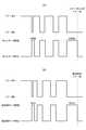
図6(a)は、トナーボトルT内のトナー空判定シーケンスを示す図である。図6(a)を用いて、トナーボトルT内のトナーが空になったか否かを判定する処理を説明する。前述したように、画像形成中に、画像データに応じたトナーが現像器140から排出される。現像器140内のトナーが無いと判定されると、トナー搬送路210から現像器140へトナーが補給される。そして、トナー搬送路210から現像器140へトナーへの補給が繰り返されると、やがて、トナー搬送路210内の第2のトナーセンサ213の検知結果から、トナー搬送路210内にトナーが無いと判定される。 FIG. 6A is a diagram showing a toner empty determination sequence in the toner bottle T. A process of determining whether or not the toner in the toner bottle T is empty will be described with reference to FIG. 6A. As described above, during image formation, toner corresponding to the image data is discharged from the
CPU400は、トナー搬送路210内にトナーが無いと判定すると、ボトルモータ201を制御してトナーボトルTを回転させる。これによりトナーボトルTからトナー搬送路210へトナーが適切に補給されれば、第2のトナーセンサ213の検知結果は、「トナー搬送路210内にトナー有り」を示すようになる。つまり、CPU400は、トナー搬送路210内のトナーが適量に保たれるように、ボトルモータ201を制御する。図6(a)の例では、ボトルモータ201を例えば5回、回転させることで、第2のトナーセンサ213の検知結果は、トナー無しからトナー有りに変化している。 When the
ここで、仮にトナーボトルT内のトナーの量が所定以下となると、トナーボトルTが回転してもトナー搬送路210内にトナーが補給されなくなる。図6(a)に示すように、トナーボトルTを例えば20回、回転させても、トナー搬送路210内にトナー無し、という検知結果が継続する。この場合、CPU400は、トナーボトルT内(収容容器内)のトナーが空となったと判定する。そしてCPU400は、上記補給情報として、トナーボトルT内のトナーが「空」であることを示す、トナー空情報=1を、当該トナーボトルTのメモリ223へ書き込む。それと共にCPU400は、記憶手段としてのRAM402に記憶されている、当該トナーボトルTの補給情報中においても、トナー空情報=1を格納する。なお、新品のトナーボトルTの補給情報におけるトナー空情報は、トナーが空でないことを示す、トナー空情報=0となっている。 Here, if the amount of toner in the toner bottle T is equal to or less than a predetermined amount, the toner will not be replenished in the
なお、トナーボトルTを20回、回転させることは、装着されたトナーボトルTからトナー搬送路210への所定の補給動作に該当する。従って、第2のトナーセンサ213の出力が、トナー搬送路210内にトナー無し、という検知結果を示した場合に、上記所定の補給動作を実施しても第2のトナーセンサ213の出力が変化しないと、トナーボトルT内のトナーが空であると判定される。そしてCPU400は、トナーボトルT内のトナーが空であることを示す情報をトナーボトルTのメモリ223へ書き込む。なお、上記所定の補給動作における回転回数は、例示した20回に限定されない。 Rotating the toner bottle T 20 times corresponds to a predetermined replenishment operation from the mounted toner bottle T to the
ところで、第2のトナーセンサ213は、基準量を基準としてトナー搬送路210内のトナーの有無を検知するとする。従って、トナー搬送路210内にトナー無し、と判定されても、必ずしもトナー搬送路210内のトナーが皆無になったことを意味しない。従って、トナーボトルT内のトナーが空であると判定されても、トナー搬送路210内に基準量以下ではあるがトナーが残っていれば、画像形成動作を継続できる可能性がある。 By the way, it is assumed that the
図6(b)は、トナー搬送路210内のトナー空判定シーケンスを示す図である。前述したように、画像形成中に、画像データに応じたトナーが現像器140から排出される。第1のトナーセンサ221は、基準量を基準として現像器140内のトナーの有無を検知する。トナーが現像器140から排出されてトナー残量が基準量を下回ると、第1のトナーセンサ221はOFF状態の信号を出力する。そして、上述したように第1のトナーセンサ221の出力が、現像器140内にトナー無し、という検知結果を示すと、CPU400は、搬送路モータ211を制御してスクリュー212を回転させる。一例として、CPU400は、搬送路モータ211を4sec駆動する。この動作が、トナー搬送路210から現像器140へトナーを補給する所定の補給動作に該当する。なお、搬送路モータ211を駆動する時間は4secに限定されない。 FIG. 6B is a diagram showing a toner empty determination sequence in the
現像器140へトナーが適切に補給されると、第1のトナーセンサ221の出力が、現像器140内にトナー有り、という検知結果を示すようになる。このように、CPU400は、現像器140内のトナーが一定量(基準量)保たれるように、搬送路モータ211を制御する。図6(b)では、搬送路モータ211を4sec駆動することで、第1のトナーセンサ221の検知結果は、トナー無しからトナー有りに変化している。 When the toner is appropriately replenished to the developing
また、トナー搬送路210内のトナーが空になると、搬送路モータ211を駆動しても現像器140内にトナーが補給されない。図6(b)に示すように、搬送路モータ211を例えば16sec駆動しても、現像器140内にトナー無し、という検知結果が継続する。この場合、CPU400は、トナー搬送路210内(バッファ部内)のトナーが空となったと判定する。従って、第1のトナーセンサ221の出力が、現像器140内にトナー無し、という検知結果を示した場合に、上記所定の補給動作を実施しても第1のトナーセンサ221の出力が変化しないと、トナー搬送路210内のトナーが空であると判定される。 Further, when the toner in the
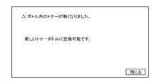
図7は、交換可能画面の一例を示す図である。この交換可能画面は、トナーボトルT内のトナーが空と判定された場合に、操作部300のタッチパネルに表示される。この交換可能画面により、トナーボトルT内のトナーが空であること、及び、トナーボトルTを新しいトナーボトルTに交換することが可能であること、がユーザに報知される。ユーザは、画像形成継続中においてもトナーボトルTの交換が可能である(これは、コンティニュアスランと呼ばれる。)。交換可能画面の「閉じるボタン」をユーザが押下すると、CPU400は、タッチパネル上の交換可能画面を消し、代わりにホーム画面を表示させる。ホーム画面は、後述する交換画面(図8)、及び警告画面(図9)とは異なる画面である。ホーム画面では例えば、ユーザは画像形成装置100の印刷設定を変更することができ、例えば、印刷枚数、印刷物の濃度、及び印刷モードを設定できる。従って、トナーボトルT内のトナーが空であると判定されたとしても、トナー搬送路210内に残トナーが有れば、ユーザはホーム画面から印刷モードを設定できる。 FIG. 7 is a diagram showing an example of a replaceable screen. This replaceable screen is displayed on the touch panel of the
図8は、交換画面の一例を示す図である。この交換画面は、トナー搬送路210内のトナーが空であると判定された場合に、操作部300のタッチパネルに表示される。この交換画面により、トナーボトルT内のトナーが空になったこと、及び、トナーボトルTを新しいトナーボトルTに交換する必要があること、がユーザに報知される。これにより、ユーザはトナーボトルTの交換を促される。交換画面の指示に従い、ユーザは画像形成装置100からトナーボトルTを取り出し(取り外し)、新しいトナーボトルTを装着する。ボトルセンサ203によってトナーボトルTが取り外されたことが検知された後に、ボトルセンサ203によってトナーボトルTが装着されたことが検知されると、CPU400は、タッチパネル上の交換画面を消し、代わりにホーム画面を表示させる。 FIG. 8 is a diagram showing an example of an exchange screen. This replacement screen is displayed on the touch panel of the
なお、交換画面が表示された状態でトナーボトルTが交換された直後は、通常、現像器140内、及びトナー搬送路210内が空である。そのためCPU400は、まずボトルモータ201を制御してトナーボトルTからトナー搬送路210へトナー補給を実行する。そしてCPU400は、第2のトナーセンサ213の出力がトナー搬送路210内にトナー有りを示すようになると、搬送路モータ211を制御し、トナー搬送路210から現像器140へのトナー補給を開始する。その後、現像器140内のトナーが有りと判定されると、画像形成装置100は画像形成動作が実行可能となる。 Immediately after the toner bottle T is replaced with the replacement screen displayed, the inside of the developing
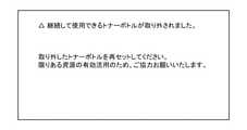
図9は、警告画面の一例を示す図である。この警告画面は、空でないまま取り外されたトナーボトルTを再装着すべきことをユーザに報知するための画面である。前述のトナーボトルT内のトナー空判定シーケンス(図6(a))によりトナーボトルT内のトナーが空であると判定される前に、トナーボトルTが取り出されると、そのトナーボトルTはそのまま廃棄されてしまうおそれがある。そこで、CPU400は、トナーボトルT内のトナーが空でない状態で取り外されて別のトナーボトルTに交換されたことを、ボトルセンサ203の検知結果から判定した場合、操作部300のタッチパネルに警告画面を表示させる。警告画面には、取り出されたトナーボトルTを再装着するように促すメッセージが表示される。これにより、ユーザが誤って交換不要なトナーボトルTを取り外して廃棄してしまうことを抑制できる。取り外したトナーボトルTをユーザが再装着すると警告画面は消え、タッチパネルにはホーム画面が表示されると共に、画像形成動作の禁止が解除される。 FIG. 9 is a diagram showing an example of a warning screen. This warning screen is a screen for notifying the user that the removed toner bottle T should be reattached without being empty. If the toner bottle T is taken out before it is determined by the toner empty determination sequence in the toner bottle T (FIG. 6A) that the toner in the toner bottle T is empty, the toner bottle T remains as it is. It may be discarded. Therefore, when the
図10は、警告画面表示処理のフローチャートである。この処理は、CPU400がROM401に格納されたプログラムをRAM402に読み出して実行することにより実現される。CPU400は、画像形成装置100の主電源がオンされた後、一定時間間隔で(例えば500msec毎に)この処理を実行する。図10の処理において、CPU400は、本発明における判定手段としての役割を果たす。 FIG. 10 is a flowchart of the warning screen display process. This process is realized by the
ステップS101において、CPU400は、ボトルセンサ203の検知結果に基づいて、トナーボトルTが取り出されたか否かを判別し、トナーボトルTが取り出されると、処理をステップS102に進める。なお、トナーボトルTが取り外されたとき、CPU400は、取り外される前に当該トナーボトルTから取得していた補給情報(製造番号を含む)を、消去することなくRAM402に保持させておく。 In step S101, the
ステップS102において、CPU400は、ボトルセンサ203の検知結果に基づいて、トナーボトルTが装着されたか否かを判別し、トナーボトルTが装着されると、処理をステップS103に進める。ステップS103では、CPU400は、新たに装着されたトナーボトルTと比較される比較対象のトナーボトルTが空であったか否かを判別する。ここで、ステップS103、S104で用いる「比較対象のトナーボトルT」には、警告画面の非表示中であれば、前回装着されていた(最後に取り外された)トナーボトルTが該当する。また、警告画面の表示中であれば、比較対象のトナーボトルTには、警告画面の表示前において最後に取り外されたトナーボトルT(つまり空でないまま取り外されたトナーボトルT)が該当する。警告画面の表示前において最後に取り外されたトナーボトルTが、前回装着されていたトナーボトルTと同一である場合もあり得る。ステップS103の判別の結果、比較対象のトナーボトルTのトナーが空であった場合(トナー空情報=1が格納されている場合)は、CPU400は、処理をステップS104に進める。一方、比較対象のトナーボトルTのトナーが空でなかった場合(トナー空情報=0が格納されている場合)は、CPU400は、処理をステップS105に進める。なお、ステップS103の判別の結果、比較対象のトナーボトルTのトナーが空であったことは、当該トナーボトルTが交換条件を満たすことに該当する。 In step S102, the
ステップS105では、CPU400は、比較対象のトナーボトルTと今回装着されたトナーボトルTの両者が同じであるか否かを、両者それぞれの補給情報中の製造番号の比較に基づき判別する。そして、製造番号同士が一致しない場合は、両者は異なるトナーボトルTであると決定されるので、CPU400は操作部300に警告画面(図9)を表示させ(ステップS108)、処理をステップS104に進める。この場合、トナーボトルTが交換条件を満たしていない状態で他のトナーボトルTへ交換された場合に該当する。一方、製造番号同士が一致する場合は、両者は同じトナーボトルTであると決定される。すなわち、空でないトナーボトルTが一旦取り外されたが、再装着されたと判定される。そこでCPU400は、警告画面を表示中であるか否かを判別し(ステップS106)、警告画面を表示中でなければ処理をステップS104に進める。一方、警告画面を表示中であれば、CPU400は、警告画面を非表示にしてから(ステップS107)、処理をステップS104に進める。 In step S105, the
ステップS104では、CPU400は、今回新たに装着されたトナーボトルTのメモリ223に記録されている補給情報を取得し、RAM402に格納されている現在のトナーボトルTの補給情報を、新たに取得した補給情報に更新する。その後、CPU400は図10の処理を終了する。詳細には、ステップS104においてCPU400は次のように処理する。まずCPU400は、警告画面の表示(ステップS108)を経た場合は、「警告画面の表示前に最後に取り外されたトナーボトルT」の補給情報を消去することなく、新たに装着されたトナーボトルTの補給情報を別途格納させる。「警告画面の表示前に最後に取り外されたトナーボトルT」の補給情報中の製造番号が保持されている場合は、これが次回の比較対象のトナーボトルTの識別情報となる。従って、警告画面の表示前に最後に取り外されたトナーボトルTは、次回のステップS103、S105において、比較対象のトナーボトルTとなる。一方、CPU400は、ステップS106または警告画面の非表示(ステップS107)を経た場合は、「警告画面の表示前に最後に取り外されたトナーボトルT」の補給情報を消去する。この場合、更新された後の補給情報中の製造番号が、次回の比較対象のトナーボトルTの識別情報となる。従って、今回装着されたトナーボトルTは、それが取り外された直後のステップS103、S105において、比較対象のトナーボトルTとなる。 In step S104, the
図10の処理によれば、空でないトナーボトルTから別のトナーボトルTに交換されると警告画面が表示される。そして、一旦取り外された空でないトナーボトルTが再装着されると警告画面が消去される。 According to the process of FIG. 10, a warning screen is displayed when the non-empty toner bottle T is replaced with another toner bottle T. Then, when the non-empty toner bottle T once removed is reattached, the warning screen is erased.
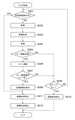
図11は、ジョブ処理のフローチャートである。この処理は、CPU400がROM401に格納されたプログラムをRAM402に読み出して実行することにより実現される。CPU400は、画像形成装置100の主電源がオンされた後、画像形成ジョブ(印刷ジョブ)が投入されると開始される。図11の処理において、CPU400は、本発明における停止手段としての役割を果たす。 FIG. 11 is a flowchart of job processing. This process is realized by the
ところで、警告画面(図9)は表示と非表示が切り替わるため、警告画面の表示動作は画像形成動作とは非同期である。また、警告画面が表示されている間、画像形成動作は禁止されるため(後述するステップS212)、画像形成動作は開始されない。図11では、画像形成動作開始後に警告画面が表示された場合に、画像形成動作の停止処理を実行してから画像形成動作を禁止状態にする処理を説明する。 By the way, since the warning screen (FIG. 9) is switched between display and non-display, the display operation of the warning screen is asynchronous with the image formation operation. Further, since the image forming operation is prohibited while the warning screen is displayed (step S212 described later), the image forming operation is not started. FIG. 11 describes a process of executing the process of stopping the image forming operation and then prohibiting the image forming operation when the warning screen is displayed after the start of the image forming operation.
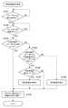
まず、画像形成ジョブの投入後、シートの給紙開始前に、ステップS201において、CPU400は、警告画面が表示中であるか否かを判別する。そして警告画面が表示中である場合は、CPU400は、画像形成の停止処理を実行し(ステップS211)、画像形成動作を禁止状態として(ステップS212)、図11の処理を終了する。ここで、画像形成の停止処理は、画像形成動作を禁止する前に、新たな給紙をすることなく且つ排紙が完了した状態とし、さらに搬送等の画像形成に関する動作を停止する処理である。従ってCPU400は、画像形成装置内にシートが残っている場合はそれを搬送して排紙させる処理を実行する。 First, after inputting the image forming job and before starting paper feeding of the sheet, in step S201, the
ステップS201の判別の結果、警告画面を表示していない場合、ステップS202で、CPU400は、給紙カセット110に収納されたシートをピックアップローラ111、給紙ローラ112及びリタードローラ113によって給紙する。次にCPU400は、ステップS203において、給紙したシートに対して画像形成を行い、ステップS204において、シートを装置外部の排紙トレイ171へ排紙する。次にCPU400は、ステップS205で、現像器140へのトナー補給が必要か否かを判定する。ステップS205において、第1のトナーセンサ221が、現像器140内にトナーがあることを示す信号を出力する場合、CPU400は現像器140へのトナー補給が必要ではないと判定する。CPU400は、現像器140へのトナー補給が必要でない場合は、継続して画像形成動作が可能であるので、処理をステップS209へ移行する。ステップS209では、CPU400は、今回の画像形成ジョブにおける画像形成すべき次ページの画像データが無いか否かを判別し、画像形成すべき次ページの画像データがある場合は、処理をステップS201に戻す。一方、画像形成すべき次ページの画像データが無い場合は、画像形成ジョブの印刷処理が終了したので、CPU400は、ステップS210で、ステップS211と同様に画像形成の停止処理を実行し、図11の処理を終了する。 If the warning screen is not displayed as a result of the determination in step S201, in step S202, the
また、ステップS205において、第1のトナーセンサ221が、現像器140内にトナーが無いことを示す信号を出力する場合、CPU400は現像器140へのトナー補給が必要であると判定する。現像器140へのトナー補給が必要である場合は、ステップS206で、CPU400は、搬送路モータ211を制御してスクリュー212を回転させてトナー補給動作を実行する。次にCPU400は、ステップS207において、前述のトナー搬送路210内のトナー空判定シーケンス(図6(b))に基づき、トナー搬送路210内のトナーが空であるか否かを判別する。そしてCPU400は、トナー搬送路210内のトナーが空でない場合は、処理をステップS209に進める。一方、トナー搬送路210内のトナーが空である場合は、CPU400は、ステップS208で、操作部300に交換画面(図8)を表示させ、処理をステップS211に進める。従って、CPU400は、画像形成動作中にトナー搬送路210内のトナーが空になると、給紙することなく且つ排紙が完了した状態で画像形成動作を禁止するよう制御する。 Further, in step S205, when the
なお、本実施の形態におけるジョブ処理においては、給紙及び排紙がページ毎に実施され、給紙されたシートが排出された後に次のシートが給紙される。従って、各ページの処理前に警告画面が表示中か否かが判別される(S201)。そのため、ステップS201の判別時点では、装置内にシートが残っていないのが通常であるため、速やかに画像形成の禁止状態に移行できる。しかしこれに限らず、排紙完了前に次のシートを給紙する構成としてもよい。この構成とする場合、画像形成装置100は連続して複数枚のシートに画像を順次形成する。CPU400は、ステップS204では排紙を開始し、シートが排紙されているか否かに拘わらず、次のステップS201では、新たにシートの給紙を開始前に、警告画面が表示中か否かを判別する。そして、警告画面が表示されている場合、CPU400は新たなシートの給紙を禁止すると共に、既に搬送路に残っているシートに対して画像形成を行い、搬送路に残っているすべてのシートに画像を形成し終えた後に、画像形成動作を停止する。なお、空でないトナーボトルTが再装着されて警告画面が表示状態から非表示状態へ変化した場合、CPU400は残りの画像を形成するために画像形成動作を再開する。 In the job processing in the present embodiment, paper feeding and paper ejection are performed page by page, and the next sheet is fed after the fed sheet is ejected. Therefore, it is determined whether or not the warning screen is being displayed before the processing of each page (S201). Therefore, at the time of determination in step S201, since it is normal that no sheet remains in the apparatus, it is possible to quickly shift to the prohibited state of image formation. However, the present invention is not limited to this, and the next sheet may be fed before the completion of paper ejection. With this configuration, the
ところで、ステップS201~S207、S209を繰り返している最中に、トナーボトルT内のトナーが空であると判定された場合は、交換可能画面(図7)が表示される。これにより、ユーザは、画像形成装置100が画像形成を停止することなく、トナーボトルTを交換できる。 By the way, if it is determined that the toner in the toner bottle T is empty while repeating steps S201 to S207 and S209, a replaceable screen (FIG. 7) is displayed. This allows the user to replace the toner bottle T without the
本実施の形態によれば、CPU400は、空でないトナーボトルTから別のトナーボトルTに交換されると警告画面を表示させる。また、CPU400は、画像形成ジョブの投入後、警告画面の表示中かどうかを判定し、警告画面の表示中の場合は、給紙することなく且つ排紙が完了した状態で画像形成動作を禁止するよう制御する。すなわち、トナーボトルTが交換条件を満たしていない状態で他のトナーボトルTへ交換された場合、搬送路に残ったシートへ画像を形成し終えた後に画像形成が停止される。よって、トナーが空でない収容容器から別の収容容器に交換された場合に、装置内にシートを残存させずに画像形成動作を禁止状態することができる。すなわち、空ではないトナーボトルが他のトナーボトルに交換された場合であっても、画像形成装置の内部にシートが残存することを抑制できる。シートが装置内部に残ることがないので、ユーザにとって装置内部からシートを取り除く作業が不要となる。また、元のトナーボトルTを再装着することで警告画面が非表示となり、画像形成動作の禁止が解除されるので、ユーザは元のトナーボトルTに戻すことで、画像形成動作を実行可能にすることができる。 According to this embodiment, the
(第2の実施の形態)
第1の実施の形態では、印刷ジョブにおけるページ毎に、警告画面が表示されているか否かを判定していた。これに対し本発明の第2の実施の形態では、ページ毎ではなく、警告画面が表示されているか否かをジョブ毎に判定する。図11に代えて図12を用いて本実施の形態を説明する。ジョブ処理以外の処理や構成は第1の実施の形態と同様である。(Second embodiment)
In the first embodiment, it is determined whether or not the warning screen is displayed for each page in the print job. On the other hand, in the second embodiment of the present invention, it is determined for each job whether or not the warning screen is displayed, not for each page. This embodiment will be described with reference to FIG. 12 instead of FIG. The processing and configuration other than the job processing are the same as those in the first embodiment.
図12は、ジョブ処理のフローチャートである。この処理は、CPU400がROM401に格納されたプログラムをRAM402に読み出して実行することにより実現される。CPU400は、画像形成装置100の主電源がオンされた後、画像形成ジョブが投入されると開始される。 FIG. 12 is a flowchart of job processing. This process is realized by the
まず、画像形成ジョブの投入後、シートの給紙開始前に、ステップS301において、CPU400は、給紙カセット110に収納されたシートをピックアップローラ111、給紙ローラ112及びリタードローラ113によって給紙する。CPU400は、続くステップS302~S307、S310、S311では、図11のステップS203~S208、S209、S210と同様の処理を実行する。なお、ステップS310での判別の結果、今回の画像形成ジョブにおける画像形成すべき次ページの画像データがある場合は、CPU400は処理をステップS301に戻す。ステップS307の後、CPU400は、ステップS308で、ステップS211と同様に画像形成の停止処理を実行し、処理をステップS309に進める。ステップS311の後、CPU400は、ステップS312で、警告画面が表示中であるか否かを判別し、警告画面が表示中でない場合は、図12の処理を終了する。一方、CPU400は、警告画面が表示中である場合は、処理をステップS309に進める。ステップS309では、CPU400は、画像形成動作を禁止状態として、図12の処理を終了する。 First, after inputting the image forming job and before starting paper feeding of the sheet, in step S301, the
本実施の形態によれば、トナーが空でない収容容器(トナーボトルT)から別の収容容器に交換された場合に、装置内にシートを残存させずに画像形成動作を禁止状態とするので、第1の実施の形態と同様の効果を奏することができる。また、元のトナーボトルTに戻すことで画像形成動作を実行可能にすることができる。 According to the present embodiment, when the toner is replaced from a non-empty container (toner bottle T) to another container, the image forming operation is prohibited without leaving a sheet in the apparatus. The same effect as that of the first embodiment can be obtained. Further, the image forming operation can be executed by returning to the original toner bottle T.
なお、本実施の形態において、複数の印刷ジョブが連結して投入された場合は、印刷ジョブの切れ目で画像形成動作を停止させてもよい。その場合、例えば、印刷ジョブ毎に画像データにジョブID情報を付与しておき、CPU400は、ステップS310で、ジョブID情報の変化により印刷ジョブの切れ目を判定する。そして、印刷ジョブの切れ目において、画像形成動作を停止した上で、警告画面が表示中であれば画像形成動作を禁止状態にしてもよい。これにより、CPU400は、画像形成ジョブの終了後に、警告画面が表示されているか否かを判別する。そしてCPU400は、警告画面が表示されている場合に、後続の画像形成ジョブがあるときは、後続の画像形成ジョブの開始前に、画像形成動作を禁止するよう制御する。 In the present embodiment, when a plurality of print jobs are connected and input, the image forming operation may be stopped at the break of the print jobs. In that case, for example, job ID information is added to the image data for each print job, and the
なお、図10のステップS108において、報知の一例として警告画面(図9)を表示させるとした。しかし、一旦取り外された、トナーが空でないトナーボトルTの再装着を促すための報知であればよく、報知の態様は問わない。従って、画面によらず音声による報知であってもよい。 In step S108 of FIG. 10, a warning screen (FIG. 9) is displayed as an example of notification. However, the notification may be any mode as long as it is a notification for prompting the reattachment of the toner bottle T whose toner is not empty once it has been removed. Therefore, the notification may be made by voice regardless of the screen.
以上、本発明をその好適な実施形態に基づいて詳述してきたが、本発明はこれら特定の実施形態に限られるものではなく、この発明の要旨を逸脱しない範囲の様々な形態も本発明に含まれる。上述の実施形態の一部を適宜組み合わせてもよい。 Although the present invention has been described in detail based on the preferred embodiments thereof, the present invention is not limited to these specific embodiments, and various embodiments within the range not deviating from the gist of the present invention are also included in the present invention. included. Some of the above-described embodiments may be combined as appropriate.
203 ボトルセンサ
400 CPU
T トナーボトル203
T toner bottle
Claims (9)
Translated fromJapanese現像剤を蓄積する現像器を有し、前記現像器の現像剤を用いて、前記搬送手段により搬送された前記シートに画像を形成する画像形成手段と、
前記現像器に補給するための現像剤を収容した収容容器が装着される装着部と、
前記装着部に装着された収容容器から前記現像器へ現像剤を補給する補給手段と、
前記装着部に装着された収容容器が交換条件を満たしていない状態で他の収容容器へ交換された場合、前記画像形成手段が前記搬送路に残ったシートへ画像を形成し終えた後に前記画像形成手段による画像形成を停止する停止手段と、
前記装着された収容容器が前記交換条件を満たしていない状態で他の収容容器へ交換された場合、前記交換条件を満たしていない収容容器の再装着を促すための報知を実施する報知手段と、を有し、
前記停止手段は、画像形成ジョブの投入後に、前記報知手段による報知が実施されているか否かを判定し、前記報知が実施されている場合に、前記画像形成手段による画像形成を停止することを特徴とする画像形成装置。A transport means for transporting the sheet along the transport path, and
An image forming means having a developing device for accumulating a developing agent and forming an image on the sheet conveyed by the conveying means by using the developing agent of the developing device.
A mounting portion on which a storage container containing a developer for replenishing the developer is mounted, and a mounting portion.
A replenishing means for replenishing the developer from the storage container mounted on the mounting portion to the developing unit, and
When the storage container mounted on the mounting portion is replaced with another storage container in a state where the replacement conditions are not satisfied, the image is obtained after the image forming means finishes forming an image on the sheet remaining in the transport path. A stop means for stopping image formation by the forming means, and a stop means.
When the mounted storage container is replaced with another storage container in a state where the replacement condition is not satisfied, a notification means for executing a notification for prompting the re-mounting of the storage container that does not meet the replacement condition, and a notification means. Have,
The stop means determines whether or not the notification by the notification means is executed after the input of the image forming job, and if the notification is executed, stops the image formation by the image forming means . An image forming device as a feature.
前記装着された収容容器は、前記判定手段により現像剤が空であると判定されたことにより前記交換条件が満たされることを特徴とする請求項1に記載の画像形成装置。It has a determination means for determining whether or not the developer in the storage container mounted on the mounting portion is empty.
The image forming apparatus according to claim 1, wherein the mounted container is satisfied with the exchange condition because the developer is determined to be empty by the determination means.
前記装着された収容容器が取り外されたことを検知する検知手段と、
前記装着された収容容器が取り外されたことが前記検知手段により検知された場合、前記取り外された収容容器に対応する前記取得手段により取得された識別情報、及び前記取り外された収容容器に関する前記判定手段の判定結果の情報を記憶する記憶手段と、を有し、
前記停止手段は、新たに装着された収容容器から取得された識別情報と前記記憶手段に記憶された識別情報との比較に基づいて、前記装着部に装着された収容容器が交換条件を満たしていない状態で他の収容容器へ交換されたか否かを判定することを特徴とする請求項2に記載の画像形成装置。An acquisition means for acquiring identification information uniquely identifying the storage container from the mounted storage container, and
A detection means for detecting that the mounted container has been removed, and
When the detection means detects that the mounted storage container has been removed, the identification information acquired by the acquisition means corresponding to the removed storage container and the determination regarding the removed storage container. It has a storage means for storing information on the determination result of the means, and has.
In the stopping means, the storage container mounted on the mounting portion satisfies the exchange condition based on the comparison between the identification information acquired from the newly mounted storage container and the identification information stored in the storage means. The image forming apparatus according to claim 2, wherein it is determined whether or not the container has been replaced with another container in a non-existent state.
Priority Applications (2)
| Application Number | Priority Date | Filing Date | Title |
|---|---|---|---|
| JP2017188362AJP7005253B2 (en) | 2017-09-28 | 2017-09-28 | Image forming device |
| US16/139,457US10444666B2 (en) | 2017-09-28 | 2018-09-24 | Image forming apparatus with removable developer container |
Applications Claiming Priority (1)
| Application Number | Priority Date | Filing Date | Title |
|---|---|---|---|
| JP2017188362AJP7005253B2 (en) | 2017-09-28 | 2017-09-28 | Image forming device |
Publications (2)
| Publication Number | Publication Date |
|---|---|
| JP2019066514A JP2019066514A (en) | 2019-04-25 |
| JP7005253B2true JP7005253B2 (en) | 2022-01-21 |
Family
ID=65806636
Family Applications (1)
| Application Number | Title | Priority Date | Filing Date |
|---|---|---|---|
| JP2017188362AActiveJP7005253B2 (en) | 2017-09-28 | 2017-09-28 | Image forming device |
Country Status (2)
| Country | Link |
|---|---|
| US (1) | US10444666B2 (en) |
| JP (1) | JP7005253B2 (en) |
Citations (5)
| Publication number | Priority date | Publication date | Assignee | Title |
|---|---|---|---|---|
| JP2001201898A (en) | 2000-01-20 | 2001-07-27 | Ricoh Co Ltd | Image recording device |
| JP2006071905A (en) | 2004-09-01 | 2006-03-16 | Fuji Xerox Co Ltd | Printing control device, method and program for making effective use of consumable article attached to the same |
| JP2015014811A (en) | 2014-10-22 | 2015-01-22 | 京セラドキュメントソリューションズ株式会社 | Image forming apparatus |
| JP2015072313A (en) | 2013-10-01 | 2015-04-16 | シャープ株式会社 | Image forming apparatus, control method of image forming apparatus, program, and recording medium |
| JP2015075701A (en) | 2013-10-10 | 2015-04-20 | シャープ株式会社 | Image forming apparatus and operation method thereof |
Family Cites Families (1)
| Publication number | Priority date | Publication date | Assignee | Title |
|---|---|---|---|---|
| JP2019066513A (en)* | 2017-09-28 | 2019-04-25 | キヤノン株式会社 | Image forming device |
- 2017
- 2017-09-28JPJP2017188362Apatent/JP7005253B2/enactiveActive
- 2018
- 2018-09-24USUS16/139,457patent/US10444666B2/enactiveActive
Patent Citations (5)
| Publication number | Priority date | Publication date | Assignee | Title |
|---|---|---|---|---|
| JP2001201898A (en) | 2000-01-20 | 2001-07-27 | Ricoh Co Ltd | Image recording device |
| JP2006071905A (en) | 2004-09-01 | 2006-03-16 | Fuji Xerox Co Ltd | Printing control device, method and program for making effective use of consumable article attached to the same |
| JP2015072313A (en) | 2013-10-01 | 2015-04-16 | シャープ株式会社 | Image forming apparatus, control method of image forming apparatus, program, and recording medium |
| JP2015075701A (en) | 2013-10-10 | 2015-04-20 | シャープ株式会社 | Image forming apparatus and operation method thereof |
| JP2015014811A (en) | 2014-10-22 | 2015-01-22 | 京セラドキュメントソリューションズ株式会社 | Image forming apparatus |
Also Published As
| Publication number | Publication date |
|---|---|
| US10444666B2 (en) | 2019-10-15 |
| JP2019066514A (en) | 2019-04-25 |
| US20190094756A1 (en) | 2019-03-28 |
Similar Documents
| Publication | Publication Date | Title |
|---|---|---|
| JP4735850B2 (en) | Consumable management apparatus, image forming apparatus, and program | |
| US7620334B2 (en) | Image forming apparatus having disablement of image formation based on detection of developer | |
| JP4671824B2 (en) | Image forming apparatus | |
| US20190094781A1 (en) | Image forming apparatus to and from which container containing developer can be mounted and removed | |
| US10401752B2 (en) | Image forming apparatus | |
| JP2015143760A (en) | image forming apparatus | |
| JP7005253B2 (en) | Image forming device | |
| JP6773017B2 (en) | Image forming device, consumables order timing notification method | |
| JP6508352B2 (en) | Image forming device | |
| JP5125641B2 (en) | Image forming apparatus and life determination method of imaging unit in the same | |
| US20170163834A1 (en) | Image forming apparatus capable of forming images based on image data, image forming method | |
| US10551783B2 (en) | Image forming apparatus | |
| JP2010281885A (en) | Image forming apparatus | |
| JP2007057732A (en) | Image forming apparatus and process cartridge | |
| JP2008122505A (en) | Image forming apparatus | |
| JP2020201355A (en) | Image forming apparatus | |
| JP4762559B2 (en) | Image forming apparatus | |
| JP2011197044A (en) | Image forming apparatus, method of controlling the same and program | |
| JP2009048112A (en) | Method for controlling conveyance of waste toner for image forming apparatus and image forming apparatus | |
| JP2006330460A (en) | Image forming apparatus | |
| JP2006106466A (en) | Image forming apparatus | |
| JP6659110B2 (en) | Image forming device | |
| JP2017156668A (en) | Image forming apparatus | |
| JP2005300738A (en) | Image forming apparatus | |
| CN114077173A (en) | Image forming apparatus and control method |
Legal Events
| Date | Code | Title | Description |
|---|---|---|---|
| A621 | Written request for application examination | Free format text:JAPANESE INTERMEDIATE CODE: A621 Effective date:20200917 | |
| A977 | Report on retrieval | Free format text:JAPANESE INTERMEDIATE CODE: A971007 Effective date:20210831 | |
| A131 | Notification of reasons for refusal | Free format text:JAPANESE INTERMEDIATE CODE: A131 Effective date:20210907 | |
| A521 | Request for written amendment filed | Free format text:JAPANESE INTERMEDIATE CODE: A523 Effective date:20211029 | |
| TRDD | Decision of grant or rejection written | ||
| A01 | Written decision to grant a patent or to grant a registration (utility model) | Free format text:JAPANESE INTERMEDIATE CODE: A01 Effective date:20211130 | |
| A61 | First payment of annual fees (during grant procedure) | Free format text:JAPANESE INTERMEDIATE CODE: A61 Effective date:20220105 | |
| R151 | Written notification of patent or utility model registration | Ref document number:7005253 Country of ref document:JP Free format text:JAPANESE INTERMEDIATE CODE: R151 |