JP7005094B2 - Septum - Google Patents
SeptumDownload PDFInfo
- Publication number
- JP7005094B2 JP7005094B2JP2018567605AJP2018567605AJP7005094B2JP 7005094 B2JP7005094 B2JP 7005094B2JP 2018567605 AJP2018567605 AJP 2018567605AJP 2018567605 AJP2018567605 AJP 2018567605AJP 7005094 B2JP7005094 B2JP 7005094B2
- Authority
- JP
- Japan
- Prior art keywords
- layer
- partition wall
- well
- wells
- microplate
- Prior art date
- Legal status (The legal status is an assumption and is not a legal conclusion. Google has not performed a legal analysis and makes no representation as to the accuracy of the status listed.)
- Active
Links
- 238000005192partitionMethods0.000claimsdescription41
- 229920002725thermoplastic elastomerPolymers0.000claimsdescription23
- 238000001704evaporationMethods0.000claimsdescription17
- 230000008020evaporationEffects0.000claimsdescription17
- 239000000853adhesiveSubstances0.000claimsdescription14
- 230000001070adhesive effectEffects0.000claimsdescription9
- 238000000034methodMethods0.000claimsdescription5
- 239000003153chemical reaction reagentSubstances0.000claimsdescription4
- 238000003780insertionMethods0.000claimsdescription4
- 230000037431insertionEffects0.000claimsdescription4
- 238000012545processingMethods0.000claimsdescription4
- 229920001577copolymerPolymers0.000claimsdescription3
- 229920001169thermoplasticPolymers0.000claimsdescription3
- 239000004416thermosoftening plasticSubstances0.000claimsdescription3
- 238000004026adhesive bondingMethods0.000claimsdescription2
- 229920006378biaxially oriented polypropylenePolymers0.000claimsdescription2
- 239000011127biaxially oriented polypropyleneSubstances0.000claimsdescription2
- 230000007246mechanismEffects0.000claimsdescription2
- 239000010410layerSubstances0.000description51
- 239000000463materialSubstances0.000description18
- 239000004743PolypropyleneSubstances0.000description13
- 229920001155polypropylenePolymers0.000description13
- 239000012790adhesive layerSubstances0.000description12
- 239000000523sampleSubstances0.000description10
- 238000002198surface plasmon resonance spectroscopyMethods0.000description6
- PPBRXRYQALVLMV-UHFFFAOYSA-NStyreneChemical compoundC=CC1=CC=CC=C1PPBRXRYQALVLMV-UHFFFAOYSA-N0.000description5
- 239000012530fluidSubstances0.000description5
- 239000007788liquidSubstances0.000description5
- 230000008901benefitEffects0.000description4
- 230000035515penetrationEffects0.000description4
- -1styrene ethylenebutylene styreneChemical class0.000description4
- 238000009423ventilationMethods0.000description4
- 238000004891communicationMethods0.000description3
- 238000000151depositionMethods0.000description3
- 239000004433Thermoplastic polyurethaneSubstances0.000description2
- 238000007792additionMethods0.000description2
- 230000008859changeEffects0.000description2
- 238000005520cutting processMethods0.000description2
- 230000008021depositionEffects0.000description2
- 238000000605extractionMethods0.000description2
- 239000011888foilSubstances0.000description2
- 238000012986modificationMethods0.000description2
- 230000004048modificationEffects0.000description2
- 229920000642polymerPolymers0.000description2
- 230000001681protective effectEffects0.000description2
- 238000005070samplingMethods0.000description2
- 229920001935styrene-ethylene-butadiene-styrenePolymers0.000description2
- 229920002803thermoplastic polyurethanePolymers0.000description2
- 238000010521absorption reactionMethods0.000description1
- 239000003522acrylic cementSubstances0.000description1
- 239000002313adhesive filmSubstances0.000description1
- 238000005273aerationMethods0.000description1
- 238000005452bendingMethods0.000description1
- 229920001400block copolymerPolymers0.000description1
- 238000011109contaminationMethods0.000description1
- 238000013461designMethods0.000description1
- 238000001514detection methodMethods0.000description1
- 229920001971elastomerPolymers0.000description1
- 238000002474experimental methodMethods0.000description1
- 238000002347injectionMethods0.000description1
- 239000007924injectionSubstances0.000description1
- 230000003993interactionEffects0.000description1
- 238000004519manufacturing processMethods0.000description1
- 238000005259measurementMethods0.000description1
- 239000000155meltSubstances0.000description1
- 230000004001molecular interactionEffects0.000description1
- 239000002861polymer materialSubstances0.000description1
- 238000002360preparation methodMethods0.000description1
- 230000004044responseEffects0.000description1
- 239000012488sample solutionSubstances0.000description1
- 238000003860storageMethods0.000description1
- 229920006132styrene block copolymerPolymers0.000description1
- 150000003440styrenesChemical class0.000description1
- 238000012360testing methodMethods0.000description1
- 229920006344thermoplastic copolyesterPolymers0.000description1
- 229920002397thermoplastic olefinPolymers0.000description1
- 229920006345thermoplastic polyamidePolymers0.000description1
- 229920005992thermoplastic resinPolymers0.000description1
- XLYOFNOQVPJJNP-UHFFFAOYSA-NwaterSubstancesOXLYOFNOQVPJJNP-UHFFFAOYSA-N0.000description1
Images


Classifications
- B—PERFORMING OPERATIONS; TRANSPORTING
- B01—PHYSICAL OR CHEMICAL PROCESSES OR APPARATUS IN GENERAL
- B01L—CHEMICAL OR PHYSICAL LABORATORY APPARATUS FOR GENERAL USE
- B01L3/00—Containers or dishes for laboratory use, e.g. laboratory glassware; Droppers
- B01L3/50—Containers for the purpose of retaining a material to be analysed, e.g. test tubes
- B01L3/508—Containers for the purpose of retaining a material to be analysed, e.g. test tubes rigid containers not provided for above
- B01L3/5085—Containers for the purpose of retaining a material to be analysed, e.g. test tubes rigid containers not provided for above for multiple samples, e.g. microtitration plates
- B01L3/50853—Containers for the purpose of retaining a material to be analysed, e.g. test tubes rigid containers not provided for above for multiple samples, e.g. microtitration plates with covers or lids
- B—PERFORMING OPERATIONS; TRANSPORTING
- B65—CONVEYING; PACKING; STORING; HANDLING THIN OR FILAMENTARY MATERIAL
- B65D—CONTAINERS FOR STORAGE OR TRANSPORT OF ARTICLES OR MATERIALS, e.g. BAGS, BARRELS, BOTTLES, BOXES, CANS, CARTONS, CRATES, DRUMS, JARS, TANKS, HOPPERS, FORWARDING CONTAINERS; ACCESSORIES, CLOSURES, OR FITTINGS THEREFOR; PACKAGING ELEMENTS; PACKAGES
- B65D51/00—Closures not otherwise provided for
- B65D51/002—Closures to be pierced by an extracting-device for the contents and fixed on the container by separate retaining means
- G—PHYSICS
- G01—MEASURING; TESTING
- G01N—INVESTIGATING OR ANALYSING MATERIALS BY DETERMINING THEIR CHEMICAL OR PHYSICAL PROPERTIES
- G01N35/00—Automatic analysis not limited to methods or materials provided for in any single one of groups G01N1/00 - G01N33/00; Handling materials therefor
- G01N35/10—Devices for transferring samples or any liquids to, in, or from, the analysis apparatus, e.g. suction devices, injection devices
- G01N35/1004—Cleaning sample transfer devices
- G—PHYSICS
- G01—MEASURING; TESTING
- G01N—INVESTIGATING OR ANALYSING MATERIALS BY DETERMINING THEIR CHEMICAL OR PHYSICAL PROPERTIES
- G01N35/00—Automatic analysis not limited to methods or materials provided for in any single one of groups G01N1/00 - G01N33/00; Handling materials therefor
- G01N35/10—Devices for transferring samples or any liquids to, in, or from, the analysis apparatus, e.g. suction devices, injection devices
- G01N35/1079—Devices for transferring samples or any liquids to, in, or from, the analysis apparatus, e.g. suction devices, injection devices with means for piercing stoppers or septums
- A—HUMAN NECESSITIES
- A61—MEDICAL OR VETERINARY SCIENCE; HYGIENE
- A61J—CONTAINERS SPECIALLY ADAPTED FOR MEDICAL OR PHARMACEUTICAL PURPOSES; DEVICES OR METHODS SPECIALLY ADAPTED FOR BRINGING PHARMACEUTICAL PRODUCTS INTO PARTICULAR PHYSICAL OR ADMINISTERING FORMS; DEVICES FOR ADMINISTERING FOOD OR MEDICINES ORALLY; BABY COMFORTERS; DEVICES FOR RECEIVING SPITTLE
- A61J1/00—Containers specially adapted for medical or pharmaceutical purposes
- A61J1/14—Details; Accessories therefor
- A61J1/1406—Septums, pierceable membranes
- B—PERFORMING OPERATIONS; TRANSPORTING
- B01—PHYSICAL OR CHEMICAL PROCESSES OR APPARATUS IN GENERAL
- B01L—CHEMICAL OR PHYSICAL LABORATORY APPARATUS FOR GENERAL USE
- B01L2200/00—Solutions for specific problems relating to chemical or physical laboratory apparatus
- B01L2200/06—Fluid handling related problems
- B01L2200/0684—Venting, avoiding backpressure, avoid gas bubbles
- B—PERFORMING OPERATIONS; TRANSPORTING
- B01—PHYSICAL OR CHEMICAL PROCESSES OR APPARATUS IN GENERAL
- B01L—CHEMICAL OR PHYSICAL LABORATORY APPARATUS FOR GENERAL USE
- B01L2200/00—Solutions for specific problems relating to chemical or physical laboratory apparatus
- B01L2200/14—Process control and prevention of errors
- B01L2200/142—Preventing evaporation
- B—PERFORMING OPERATIONS; TRANSPORTING
- B01—PHYSICAL OR CHEMICAL PROCESSES OR APPARATUS IN GENERAL
- B01L—CHEMICAL OR PHYSICAL LABORATORY APPARATUS FOR GENERAL USE
- B01L2300/00—Additional constructional details
- B01L2300/04—Closures and closing means
- B01L2300/041—Connecting closures to device or container
- B01L2300/044—Connecting closures to device or container pierceable, e.g. films, membranes
- B—PERFORMING OPERATIONS; TRANSPORTING
- B01—PHYSICAL OR CHEMICAL PROCESSES OR APPARATUS IN GENERAL
- B01L—CHEMICAL OR PHYSICAL LABORATORY APPARATUS FOR GENERAL USE
- B01L2300/00—Additional constructional details
- B01L2300/04—Closures and closing means
- B01L2300/046—Function or devices integrated in the closure
- B01L2300/048—Function or devices integrated in the closure enabling gas exchange, e.g. vents
- B—PERFORMING OPERATIONS; TRANSPORTING
- B01—PHYSICAL OR CHEMICAL PROCESSES OR APPARATUS IN GENERAL
- B01L—CHEMICAL OR PHYSICAL LABORATORY APPARATUS FOR GENERAL USE
- B01L2300/00—Additional constructional details
- B01L2300/08—Geometry, shape and general structure
- B01L2300/0887—Laminated structure
- B—PERFORMING OPERATIONS; TRANSPORTING
- B01—PHYSICAL OR CHEMICAL PROCESSES OR APPARATUS IN GENERAL
- B01L—CHEMICAL OR PHYSICAL LABORATORY APPARATUS FOR GENERAL USE
- B01L3/00—Containers or dishes for laboratory use, e.g. laboratory glassware; Droppers
- B01L3/50—Containers for the purpose of retaining a material to be analysed, e.g. test tubes
- B01L3/508—Containers for the purpose of retaining a material to be analysed, e.g. test tubes rigid containers not provided for above
- B01L3/5082—Test tubes per se
- B01L3/50825—Closing or opening means, corks, bungs
Landscapes
- Health & Medical Sciences (AREA)
- Chemical & Material Sciences (AREA)
- Analytical Chemistry (AREA)
- General Health & Medical Sciences (AREA)
- Immunology (AREA)
- Biochemistry (AREA)
- Life Sciences & Earth Sciences (AREA)
- General Physics & Mathematics (AREA)
- Physics & Mathematics (AREA)
- Pathology (AREA)
- Clinical Laboratory Science (AREA)
- Hematology (AREA)
- Chemical Kinetics & Catalysis (AREA)
- Engineering & Computer Science (AREA)
- Mechanical Engineering (AREA)
- Automatic Analysis And Handling Materials Therefor (AREA)
- Sampling And Sample Adjustment (AREA)
- Laminated Bodies (AREA)
- Devices For Use In Laboratory Experiments (AREA)
Description
Translated fromJapanese本発明は、検体もしくは試薬ウェルまたは容器を覆い、ピペット針などのサンプリング先端がウェルまたは容器にアクセスすることを可能にするタイプの隔壁に関する。特に、排他的ではないが、本発明は、同様の間隔を空けたピペット針のアレイによってアクセスされることを意図している概して小容量の試薬または検体ウェルのアレイを有する、マイクロタイタプレートとしても知られる、いわゆるマルチウェルマイクロプレートの複数のウェルを覆う隔壁に関する。 The present invention relates to a type of septum that covers a specimen or reagent well or container and allows a sampling tip, such as a pipette needle, to access the well or container. In particular, although not exclusive, the invention is also as a microtiter plate with an array of generally small volume reagents or sample wells intended to be accessed by an array of pipette needles with similar spacing. With respect to the known bulkhead covering multiple wells of a so-called multi-well microplate.
マイクロプレートカバーの主な機能は、特にウェルの内容物がおよそ1日または1週間保存される場合に、検体ウェルからの蒸発を抑制し、ウェルを汚染から保護することである。実用目的のために、カバーは、所望の材料がウェルに載置された後にユーザによって装着可能であるべきであるが、カバーを装着した後にピペット針などを介して材料をウェルに挿入することが、以下に定義される本発明によって可能である。このような機能は、エラストマ隔壁を使用して従来通り達成することができるが、いくつかの針穿刺後のそのような隔壁の耐久性は悪く、蒸発の増加をもたらす。 The main function of the microplate cover is to suppress evaporation from the sample well and protect the well from contamination, especially if the contents of the well are stored for approximately 1 day or 1 week. For practical purposes, the cover should be user attachable after the desired material has been placed in the well, but after the cover has been attached the material can be inserted into the well, such as through a pipette needle. , Is possible by the present invention as defined below. Such a function can still be achieved using elastomeric septa, but the durability of such septa after some needle punctures is poor, resulting in increased evaporation.
針が隔壁を通して挿入されたときに隔壁が伸長して針の周りをシールするように、ゴム状の隔壁をウェル上に設けることが知られている。こうした場合、例えば液体のような材料をウェルから引き抜く、または材料をウェル内に堆積させようとすると、ウェル内の圧力の減少または上昇を引き起こす可能性がある。これにより、針内での材料の吸収があまりにも少なくなるか、またはウェル内に堆積される材料が不十分となる。ウェルの通気は可能であるが、これはウェル内の蒸発を増加させるために不都合である。 It is known to provide a rubber-like partition on the well so that the partition extends and seals around the needle when the needle is inserted through the partition. In such cases, pulling a material, such as a liquid, from the well or attempting to deposit the material in the well can cause a decrease or increase in pressure in the well. This results in too little material absorption in the needle or insufficient material deposited in the wells. Aeration of the wells is possible, but this is inconvenient because it increases evaporation in the wells.
本発明者らは、蒸発を抑制し、かつ通気を行ってマイクロプレートウェル内の圧力変化を軽減するという2つの問題に対処するために新しい設計の隔壁が必要であることを認識した。本発明の実施形態は、これらの問題に対処する。 We have recognized the need for newly designed bulkheads to address the two issues of controlling evaporation and ventilating to mitigate pressure changes in microplate wells. Embodiments of the present invention address these issues.
例えば、複数の針がマイクロプレートのウェルのアレイの間隔と一致するようにアレイ状に配置され、それにより複数のサンプルをウェルから回収する、またはウェル内に堆積させることを可能にする、いわゆるオートサンプラで使用されるタイプのサンプリング針と組み合わせてカバーを使用する場合、さらなる課題が生じる。典型的には、このようなオートサンプラを使用するときに針を隔壁に連続的に挿入すると、閉じない穴が生じ、これにより蒸発が増加する。 For example, multiple needles are arranged in an array to match the spacing of the array of wells on the microplate, which allows multiple samples to be collected from the wells or deposited in the wells, the so-called auto. Further challenges arise when using the cover in combination with the type of sampling needle used in the sampler. Typically, continuous insertion of the needle into the septum when using such an autosampler results in a non-closed hole, which increases evaporation.
オートサンプラ針が低い力でサンプルに到達することができるように再シール可能である市販のマイクロプレートカバーが利用可能であるが、それらは針によって移動するフラップ/スリットを有する。このようなカバーの試験では、フラップによりしっかりとシールを行えないため、著しい蒸発を示す。さらに、フラップ/スリットは、ウェル内に曲がるためにウェル内の作業容積を減少させ、これはフラップがウェルの内容物に接触し得る危険性があるために望ましくない。いくつかのウェルプレートカバーは再使用可能であり、マイクロプレートウェル内に押し下げられる96個のキャップとして設計されたマットとして形成される。それらは著しくウェルの作業容積を減少させ、本質的に圧縮されたゴムは、貫通するには高い力が必要となる。従来の96ウェルのホイルは、最初の貫通前は蒸発が少ないが、貫通による蒸発が始まった後はこれらのホイルは針の外側から液体を拭き取らないので、いわゆる液体のキャリーオーバー(針/ピペットの外側の余分な液体)が問題である。 Commercially available microplate covers are available that can be resealed so that the autosampler needle can reach the sample with low force, but they have flaps / slits that are moved by the needle. Testing of such covers shows significant evaporation as the flaps do not provide a secure seal. In addition, flaps / slits reduce the working volume in the wells due to bending into the wells, which is not desirable due to the risk that the flaps may come into contact with the contents of the wells. Some well plate covers are reusable and are formed as mats designed as 96 caps that are pushed down into the microplate wells. They significantly reduce the working volume of the wells, and the essentially compressed rubber requires high force to penetrate. Traditional 96-well foils evaporate less before the first penetration, but after the evaporation by penetration begins, these foils do not wipe the liquid from the outside of the needle, so so-called liquid carryover (needle / pipette). The extra liquid on the outside of the) is the problem.
本発明者らは、複数回貫通した後でも閉じるので蒸発を低減し、挿入力を低く保ちつつ針を拭きながら引き抜く隔壁型カバーに特定の材料を使用することができることを認識した。本発明の実施形態は、この認識に対処する。 The inventors have recognized that a particular material can be used for the bulkhead cover, which closes even after multiple penetrations, reducing evaporation and pulling out while wiping the needle while keeping the insertion force low. Embodiments of the invention address this recognition.
本発明の第1の態様によれば、第1の外層であって、針が層を通して挿入されるときに形成される開口を少なくとも部分的に閉じることが可能な弾性共重合体を含むかまたはそれからなる第1の外層と、隔壁が取り付け可能なウェルまたは容器の口領域に隣接して隔壁を接着するための接着性の第2の層とを含む、自己接着性層状隔壁が提供される。 According to a first aspect of the invention, the first outer layer comprises or contains an elastic copolymer capable of at least partially closing the openings formed when the needle is inserted through the layer. A self-adhesive layered bulkhead is provided comprising a first outer layer comprising a second layer of adhesive for adhering the bulkhead adjacent to a well or container mouth region to which the bulkhead can be attached.
好ましくは、第1の層は、口領域の通気孔を除いて、口領域上に実質的に連続して延びる。 Preferably, the first layer extends substantially continuously over the mouth area, except for the vents in the mouth area.
好ましくは、第2の層は、口領域内に部分的にまたは完全に存在しない。 Preferably, the second layer is partially or completely absent within the mouth region.
好ましくは、隔壁は、第1および第2の層の間に第3の層を含み、前記第3の層は、第1の層に熱結合することが可能であり、かつ第2の層に接着することが可能な熱可塑性層を含むかまたはそれからなる。 Preferably, the partition wall comprises a third layer between the first and second layers, the third layer being capable of thermally bonding to the first layer and to the second layer. Includes or consists of a thermoplastic layer that can be adhered.
好ましくは、第3の層は、軸方向または二軸方向に配向したポリプロピレンフィルムである。 Preferably, the third layer is an axially or biaxially oriented polypropylene film.
好ましくは、第3の層は、隔壁を通す針の挿入前は口領域を横切って連続的である。 Preferably, the third layer is continuous across the mouth area prior to insertion of the needle through the septum.
好ましくは、第1の層は、第3および第2の層に面するその層の表面の口領域に凹部を含み、好ましくは通気孔は、凹部内に形成される。 Preferably, the first layer comprises a recess in the mouth region of the surface of the layer facing the third and second layers, preferably vents are formed within the recess.
好ましくは、第1の層は、熱可塑性エラストマ(TPE)、場合によりスチレンブロック共重合体、例えばスチレン系熱可塑性エラストマTPE-Sから、さらに場合によりスチレンエチレンブチレンスチレン(SEBS)により形成される。 Preferably, the first layer is formed from a thermoplastic elastomer (TPE), optionally a styrene block copolymer, such as a styrene-based thermoplastic elastomer TPE-S, and optionally a styrene ethylenebutylene styrene (SEBS).
好ましくは、第1および第3の層は、例えば熱と圧力を組み合わせて使用して共に結合される。 Preferably, the first and third layers are coupled together using, for example, a combination of heat and pressure.
本発明の第2の態様によれば、間隔を空けたウェルのアレイを含むマルチウェルマイクロプレートが提供され、少なくとも1つ、好ましくはすべての前記ウェルは、第1の態様による自己接着性層状隔壁によって覆われる。 According to a second aspect of the invention, a multi-well microplate containing an array of spaced wells is provided, at least one, preferably all said wells, being a self-adhesive layered partition wall according to the first aspect. Covered by.
本発明のさらなる態様によれば、第2の態様による少なくとも1つのマルチウェルプレートを含む、自動化サンプル処理を含むSPR機器または高分解能顕微鏡が提供される。 According to a further aspect of the invention, there is provided an SPR instrument or high resolution microscope comprising automated sample processing, comprising at least one multi-well plate according to the second aspect.
本発明のさらなる態様によれば、1つまたは複数の試薬もしくは検体ウェルにおける蒸発を抑制するための方法が提供され、方法は、第1の態様による隔壁でそのまたは各ウェルを覆うことと、前記隔壁をそのまたは各ウェルの口の周りに接着することとを含む。 A further aspect of the invention provides a method for suppressing evaporation in one or more reagents or sample wells, wherein the method comprises covering the or each well with a septum according to the first aspect. It involves gluing the bulkhead around its or the mouth of each well.
本発明の実施形態は、サンプルの抽出またはサンプルの堆積中にウェルを通気する一方で蒸発を除去または低減する、自己接着性隔壁を提供する。本発明のさらなる利点および利益は、以下の詳細な説明に照らし、当業者にとって容易に明らかになるであろう。 Embodiments of the invention provide self-adhesive septa that aerate wells during sample extraction or sample deposition while removing or reducing evaporation. Further advantages and benefits of the present invention will be readily apparent to those of skill in the art in the light of the following detailed description.
本発明は、添付の図面を参照して、より詳細に説明される。 The present invention will be described in more detail with reference to the accompanying drawings.
図1は、以下に定義される複数の層を有する本発明による隔壁10の断面図を示す。隔壁10は、図2に示すようにウェル7の上に接着されることが意図されており、針9または他のピペットデバイスが隔壁を穿孔することを可能にする。 FIG. 1 shows a cross-sectional view of a
隔壁10は、弾性射出成形された共重合体、この場合、スチレン系の熱可塑性エラストマ(TPE)の形態のブロック共重合体、例えばスチレン系熱可塑性エラストマTPE-Sから、Elasto Hexpol TPEから商品名Dryflexで入手可能なスチレンエチレンブチレンスチレン(SEBS)により形成された第1の層12から形成される。TPE-SEBS層12は、外向きの表面13と、内向きの表面15と、内向きの表面15の凹部14と、凹部14と外向きの表面13との間の流体連通を形成する通気開口16とを有する。隔壁10は、市販の感圧性低表面エネルギーアクリル系接着フィルム、この場合、3Mによって供給され、ポリエステル担体から形成され、担体の各面が前記接着剤、例えば3Mが販売する300LSE接着剤を有する製造者コード93015LEの両面接着フィルムから形成された第2の層22と、ポリマー材料、例えば軸方向または二軸方向に配向された、すなわち機械伸長されたポリプロピレン(PP)の連続フィルムから形成された第3の中間層32とをさらに含む。接着層の有無にかかわらず、PP層32は、TPE層12に熱結合され、すなわち面15はPP層32の対応する表面と接触され、約140℃の温度で約5秒間、約5バールの力で圧縮され、同じ圧力を維持しながらさらなる時間冷却することを可能にする。接着層22には剥離保護フィルム42が貼り付けられており、これは使用前に接着剤を保存するために使用直前に除去される。ウェル7の口領域17上に載置されることが意図されている領域24は、接着剤がないかまたは実質的になく、凹部14が口領域24と一致することに留意されたい。この接着剤のない領域は、接着層のディスク(すなわち、両面フィルム)を前記フィルムから切断することによって形成される。 The
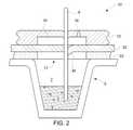
図2は、マイクロプレート5のウェル7を覆う、使用中の隔壁10の断面図を示す。図は、ウェル7に含まれる検体3の中に延びるピペットタイプの中空針9によって穿孔された隔壁10を示しているが、前記穿孔の前に、接着層22によって提供される接着シールにより、そしてウェル7の口17を閉じる連続PPポリマー層32によって隔壁10がウェル口17を覆って蒸発に対するシールを行うことは容易に明らかであろう。 FIG. 2 shows a cross-sectional view of a
引き続き図2を参照すると、下降する針9は、TPE層12を穿孔し、TPE材料の弾力性により、材料を引き裂いたり切断したりするのではなく、その材料を脇に押し付けて針の周りにシールを形成する。そして針はPP層32を通って切断し、フラップ34またはPP材料のスプリットを形成し、これは針の周りをシールするが、むしろ、ウェル7と凹部14との間の、そして通気孔16を介したウェル7の外側への流体連通を可能にする。ピペットとして作用する針への、または針からの流体材料の抽出または堆積は、差圧に関連する問題なしに行うことができる。加えて、接着層22は領域24に存在せず、これは針の接着剤による汚染が生じないという利点を有する。 Continuing with reference to FIG. 2, the descending
図3は、針9が除去された隔壁10の断面図を示す。この図において、TPE層12は、TPE材料の弾力性の結果として閉じられた、または実質的に閉じられた穿孔19を有する。この弾力性はまた、針が除去されるときに針を拭き取るように作用し、針の外側の周りの余分な流体が除去されるか、または実質的に除去されるため、これは針が供給された高分解能機器にとっては非常に有利である。PPフィルムのフラップ34は、ある程度その未切断位置に戻されなければならないが、ウェル7の完全なシールを形成しない。それにもかかわらず、その閉じられたまたは半分閉じられたフラップ34、および凹部14によって形成されたデッドスペースにより生じる限られた流体連通は、蒸発が問題にならないように、ウェル7内の液体の実質的な蒸発を抑制する。 FIG. 3 shows a cross-sectional view of the
図4は、マルチウェルマイクロプレート105のすべてのウェルに適用された隔壁100を示しており、この場合、12×8(96)ウェルのマイクロプレートの12個のウェル107を示す。実際には、剥離フィルム142(図5および図6)は除去され、接着層132(図5および図6)がマイクロプレート105と位置合わせされることで接着剤のない領域がウェル107の口の上に落ち、それによって図2および図3に示す配置と同様に各ウェル107の隔壁が提供される。使用中、プレート105は、オートサンプラ200の作業台201に載置され、オートサンプラ200は、機構(図示せず)によって少なくとも上下(Z)ならびに左右(X)に、そしてしばしばXおよびZ(Y)に垂直な方向、すなわち、図示のように用紙の内外に移動するように制御され、したがって二次元アレイにおける針109の2軸または3軸移動を提供する複数のアレイ状の針109を含むデバイスである。オートサンプラ針109は、使用中に集合的に駆動されて隔壁100をZ方向に貫通し、それぞれのウェル107の内容物103の少なくとも一部を収集するか、あるいは材料をウェル内に堆積させる。 FIG. 4 shows a
図5および図6は、隔壁100の構成をより詳細に示す。隔壁100の構成は、図1、図2および図3に関連して説明した構成と同様であり、同様の構成要素は同様の参照符号を有するが、図5および図6では前に数字「1」を付している。 5 and 6 show the configuration of the
図5は、通気開口116を有する、TPE層112の上表面113を示す。その層112はPP層132に熱結合され、次に接着層122および剥離フィルム142に接着され、そして除去を容易にするために2つの半体144に分割される。各層は、図4に示すマイクロプレート105に接続するために使用される層状構成要素の外側に露出した2つの翼部136だけを残して、共通の位置合わせ穴50を使用して位置合わせされる。 FIG. 5 shows the
図6は、各構成要素の下側、特にTPE層の下面115の複数の凹部114を示し、これらの各々は、接着剤のない口領域124と概ね一致する。 FIG. 6 shows the underside of each component, in particular the plurality of recesses 114 on the
2つの実施形態のみが説明され示されているに過ぎないが、本明細書で特許請求される本発明から逸脱することなく上記に対する修正、追加および省略が可能であることは、当業者には容易に明らかであろう。以下は、そのような修正、追加または省略の非網羅的な例である:
1)層をより明瞭に視覚化するために、図面は縮尺通りではない層を示している。実際には、TPE層12/112は、好ましくは合計で約0.8~1.2mmの厚さであるが、これは針の貫通が意図され、0.3mmの直径を有する開口16が位置する凹部14/114の厚さの約半分に過ぎない。PP層32/132は、好ましくは約10~20μmの厚さであり、接着層22/122は、好ましくは約150~200μmに剥離フィルムの厚さを加えた厚さである。したがって、8ミリメートル以上の深さとすることができる図示のウェルと比較して、隔壁はやや大きめに示されている。しかし、実用的な厚さの層であれば十分である。Although only two embodiments have been described and shown, those skilled in the art will appreciate that modifications, additions and omissions to the above may be made without departing from the invention claimed herein. It will be easy to see. The following is a non-exhaustive example of such modifications, additions or omissions:
1) In order to visualize the layers more clearly, the drawings show the layers that are not on scale. In practice, the
2)特定の材料は、本発明を実施するための1つの方法を提供するために記載されている。しかし、他の材料が実用的な変形であることは明らかであろう。例えば、記載されたTPE層12/112は代替的に、任意の針穿刺を完全にまたは実質的に「自己閉鎖」するのに十分な弾力性および靱性、すなわち適度な長さに伸張され、そして応力が除去されると、実質的にその元の形状に戻る能力を有する他の弾性熱可塑性エラストマから形成することができる。TPEの別の利点は、著しいクリープが存在しないことであり、これは隔壁が時間が経過してもその形状を保持することを意味する。TPEは、従来の熱可塑性樹脂と同様に溶融物として成形することができ、それによって製造コストを低減することができる。他の代替のTPE材料、例えば:熱可塑性オレフィン(TPE-o);熱可塑性ポリウレタン(TPU);熱可塑性コポリエステル;熱可塑性ポリアミドを使用することができる。 2) Specific materials are described to provide one method for carrying out the present invention. However, it will be clear that other materials are practical variants. For example, the described
3)隔壁10および100は、広範囲の用途に使用することができるが、特にその適用性は、少量の蒸発でも測定結果を大きく変える可能性がある高分解能顕微鏡、および表面プラズモン共鳴(SPR)機器のような特に敏感な機器によって分析されることを意図したサンプルの調製および保存におけるそれらの使用である。SPR機器は、センサ表面から約150nm以内の屈折率の変化に敏感な検出原理を使用して、リアルタイムで分子相互作用を監視する。2つの結合パートナー間の相互作用を調べるために、一方のパートナーを表面に結合し、他方を1つまたは複数のウェル7/107から収集された材料を含むサンプル溶液の連続流中で表面上を通過させた。SPR応答は、表面近くの質量濃度の変化に正比例する。したがって、前記ウェル内での蒸発は、SPR機器によって提供される読み取り値に直接影響する。このような機器は、自動化マルチウェルプレート処理およびサンプル収集システム(オートサンプラと呼ばれることもあり、図4に関連して上述した)を使用することがあるので、本明細書に記載の隔壁は、そのような使用に理想的である。隔壁10および100は、典型的には96、384、または1536ウェルを有するプレートが二次元アレイに形成されたマルチウェルプレートを覆うことが意図されているが、例えば手動で操作可能なサンプル収集針を用いて、それらが単一のサンプルウェルにも適用することができることは明らかであろう。隔壁10および100は、ユーザによってそれぞれのウェルに装着されるのが好ましいが、ウェルに供給されて既に接着されていることもあり、この場合、剥離フィルム42/142を使用する必要はない。実際には、隔壁は接着層を省略することもできるが、隔壁が層12/112および32/132だけを含むように、層32/132をそれぞれのウェルまたは複数のウェルの周りに直接熱結合させることもできる。上述の設計の隔壁を使用した実験は、50μlの水で満たされたウェルの場合に、最初の穿刺後、すなわち図3に示すように0.4%未満の蒸発を示し、それによって上述の層状構成の有効性を実証した。 3) The
3 検体
5 マイクロプレート
7 ウェル
9 中空針
10 隔壁
12 第1の外層/TPE-SEBS層
13 外向きの表面
14 凹部
15 内向きの表面
16 通気開口/通気孔
17 口領域/ウェル口
19 穿孔
22 第2の層/接着層
24 口領域
32 第3の中間層/連続PPポリマー層
34 フラップ
42 剥離保護フィルム
50 位置合わせ穴
100 隔壁
103 内容物
105 マルチウェイマイクロプレート
107 ウェル
109 オートサンプラ針
112 TPE層
113 上表面
114 凹部
115 下面
116 通気開口
122 接着層
124 口領域
132 接着層/PP層
136 翼部
142 剥離フィルム
144 半体
200 オートサンプラ
201 作業台3
Claims (13)
Translated fromJapanese前記隔壁(10、100)が、前記第1および第2の層(12、22、112、122)の間に第3の層(32、132)をさらに含み、前記第3の層(32、132)が、熱可塑性層からなり、
前記第3の層(32、132)が、前記隔壁(10、100)を通す針(9、109)の挿入前は前記口領域(17、24、124)を横切って連続的である、自己接着性層状隔壁(10、100)。A self-adhesive layered partition wall (10, 100), a first outer layer (12, 112), formed when the needle (9, 109) is inserted through the layer (12, 112). A first outer layer (12, 112) made of an elastic copolymer capable of at least partially closing the openings (16, 116) and a well (7, 107) to which the partition wall (10, 100) can be attached. Alternatively, it comprises an adhesive second layer (22, 122) for adhering the partition wall (10, 100) around the mouth region (17, 24, 124) of the container.
The partition wall (10, 100) further comprises a third layer (32, 132) between the first and second layers (12, 22, 112, 122), and the third layer (32, 132) consists of a thermoplastic layer
The third layer (32, 132) is continuous across the mouth region (17, 24, 124) prior to insertion of the needle (9, 109) through the partition (10, 100), self. Adhesive layered partition walls (10, 100).
Applications Claiming Priority (2)
| Application Number | Priority Date | Filing Date | Title |
|---|---|---|---|
| IN201611023320 | 2016-07-07 | ||
| PCT/US2017/040933WO2018009689A1 (en) | 2016-07-07 | 2017-07-06 | Septa |
Publications (2)
| Publication Number | Publication Date |
|---|---|
| JP2019529869A JP2019529869A (en) | 2019-10-17 |
| JP7005094B2true JP7005094B2 (en) | 2022-02-04 |
Family
ID=59485412
Family Applications (1)
| Application Number | Title | Priority Date | Filing Date |
|---|---|---|---|
| JP2018567605AActiveJP7005094B2 (en) | 2016-07-07 | 2017-07-06 | Septum |
Country Status (5)
| Country | Link |
|---|---|
| US (1) | US11179725B2 (en) |
| EP (1) | EP3481552B1 (en) |
| JP (1) | JP7005094B2 (en) |
| CN (1) | CN109475867B (en) |
| WO (1) | WO2018009689A1 (en) |
Families Citing this family (6)
| Publication number | Priority date | Publication date | Assignee | Title |
|---|---|---|---|---|
| US11467136B2 (en)* | 2017-12-20 | 2022-10-11 | Chromatography Research Supplies, Inc. | Chambered septum |
| EP3563929B1 (en)* | 2018-04-30 | 2022-04-13 | Firmenich SA | Apparatus for customized production of a flavoring agent mix |
| US11548008B2 (en) | 2018-07-17 | 2023-01-10 | Labcon, North America | Laboratory liquid handler head check planarity guide |
| FR3098798B1 (en)* | 2019-07-17 | 2023-12-22 | Erba Diagnostics Ltd | Reagent storage container including improved sealing sampling passage |
| EP3825004A1 (en)* | 2019-11-22 | 2021-05-26 | Koninklijke Philips N.V. | New multi-functional fluidic device for clamping biopsies |
| WO2024211726A2 (en)* | 2023-04-07 | 2024-10-10 | Integrated Liner Technologies, Inc. | Cap assembly and methods of using the same |
Citations (3)
| Publication number | Priority date | Publication date | Assignee | Title |
|---|---|---|---|---|
| JP2006284350A (en) | 2005-03-31 | 2006-10-19 | Fuji Photo Film Co Ltd | Dispenser, attaching method of pipette chip of dispenser and measuring instrument utilizing attenuation of total reflection |
| JP2010099036A (en) | 2008-10-24 | 2010-05-06 | Canon Inc | Container for treating biopolymer solution, and method for treating biopolymer solution |
| WO2012105171A1 (en) | 2011-01-31 | 2012-08-09 | コニカミノルタホールディングス株式会社 | Inspection chip, and inspection chip set provided with the inspection chip |
Family Cites Families (16)
| Publication number | Priority date | Publication date | Assignee | Title |
|---|---|---|---|---|
| US4632673A (en)* | 1983-06-15 | 1986-12-30 | Hantaaki Oy | Pierceable port for containers |
| SE470396B (en)* | 1992-12-04 | 1994-02-14 | Dicamed Ab | Valve device for aseptic injection and withdrawal of medical fluid in / out of containers and its use |
| AU7450296A (en)* | 1995-10-20 | 1997-05-07 | Beckman Instruments, Inc. | Vented probe and method for adding and removing a sample from a container |
| JP2001527438A (en)* | 1997-04-08 | 2001-12-25 | インジェクティムド インコーポレイテッド | Blood collection method and device |
| AU4424299A (en)* | 1999-02-01 | 2000-08-18 | 3M Innovative Properties Company | Poly(alpha-olefin) adhesive cover tapes for analytical receptacles |
| US6716396B1 (en)* | 1999-05-14 | 2004-04-06 | Gen-Probe Incorporated | Penetrable cap |
| US20020083686A1 (en)* | 2000-09-29 | 2002-07-04 | Audino Deborah C. | Heat sealing septum for storage plates |
| US6811752B2 (en)* | 2001-05-15 | 2004-11-02 | Biocrystal, Ltd. | Device having microchambers and microfluidics |
| US7854896B2 (en)* | 2001-09-25 | 2010-12-21 | Becton, Dickinson And Company | Closed system storage plates |
| GB0318242D0 (en)* | 2003-08-04 | 2003-09-03 | Glaxosmithkline Biolog Sa | Novel device |
| EP2086622A2 (en) | 2006-10-27 | 2009-08-12 | Sierra Molecular Corporation | Penetratable septum cap |
| US8783484B2 (en)* | 2007-08-31 | 2014-07-22 | Saint-Gobain Performance Plastics Corporation | Septa |
| US20110263461A1 (en) | 2010-04-23 | 2011-10-27 | Kumar Kastury | Methods and devices for collecting samples in a high throughput format |
| CN201759855U (en)* | 2010-06-30 | 2011-03-16 | 安徽双鹤药用包装有限公司 | Novel pull ring type combined cover for transfusion |
| CN203450544U (en)* | 2013-06-28 | 2014-02-26 | 安徽双鹤药用包装有限公司 | Bottle cover |
| CN105106014A (en)* | 2015-09-16 | 2015-12-02 | 安徽双鹤药用包装有限公司 | Infusion bottle cover |
- 2017
- 2017-07-06CNCN201780041900.2Apatent/CN109475867B/enactiveActive
- 2017-07-06USUS16/315,905patent/US11179725B2/enactiveActive
- 2017-07-06EPEP17745901.3Apatent/EP3481552B1/enactiveActive
- 2017-07-06JPJP2018567605Apatent/JP7005094B2/enactiveActive
- 2017-07-06WOPCT/US2017/040933patent/WO2018009689A1/ennot_activeCeased
Patent Citations (3)
| Publication number | Priority date | Publication date | Assignee | Title |
|---|---|---|---|---|
| JP2006284350A (en) | 2005-03-31 | 2006-10-19 | Fuji Photo Film Co Ltd | Dispenser, attaching method of pipette chip of dispenser and measuring instrument utilizing attenuation of total reflection |
| JP2010099036A (en) | 2008-10-24 | 2010-05-06 | Canon Inc | Container for treating biopolymer solution, and method for treating biopolymer solution |
| WO2012105171A1 (en) | 2011-01-31 | 2012-08-09 | コニカミノルタホールディングス株式会社 | Inspection chip, and inspection chip set provided with the inspection chip |
Also Published As
| Publication number | Publication date |
|---|---|
| EP3481552A1 (en) | 2019-05-15 |
| WO2018009689A1 (en) | 2018-01-11 |
| US20190308189A1 (en) | 2019-10-10 |
| JP2019529869A (en) | 2019-10-17 |
| CN109475867B (en) | 2022-09-13 |
| EP3481552B1 (en) | 2020-07-01 |
| US11179725B2 (en) | 2021-11-23 |
| CN109475867A (en) | 2019-03-15 |
Similar Documents
| Publication | Publication Date | Title |
|---|---|---|
| JP7005094B2 (en) | Septum | |
| EP1302243B1 (en) | Closed system storage plates | |
| US12121893B2 (en) | Pinch to open sample collection device | |
| US7981054B2 (en) | All-in-one biological specimen collecting, transporting and analyzing device | |
| AU684548B2 (en) | Assaying device | |
| US11130137B2 (en) | Diagnostic cartridges having flexible seals | |
| TWI693387B (en) | A disposable test kit | |
| KR102728424B1 (en) | Specimen vial container containing plurality of liquid | |
| US20060188404A1 (en) | Method and article for sealing a microplate | |
| CN107015013A (en) | Fluid holding plate and analysis box and the system and method for preparing measure | |
| US20090048534A1 (en) | Device for the Withdrawal, collection and Transport of Biological Specimens | |
| US20090216155A1 (en) | Test Device | |
| JP2009526210A (en) | Sample container for containing a small amount of liquid for analysis | |
| WO2017122372A1 (en) | Specimen collection device, holder for specimen collection device, and specimen pre-processing method that uses specimen collection device | |
| JP4938393B2 (en) | Microscope specimen plate | |
| US20190329257A1 (en) | System for diagnosing male infertility | |
| JP2008029244A (en) | Well plate | |
| US20180024073A1 (en) | Reach-extended test strip | |
| US20160220992A1 (en) | Accurate volume fluid collection card system | |
| JP2005172802A (en) | Plate for microscopic specimen | |
| JPH08160031A (en) | Mixing test method for visual observation of chemical reaction and mixing test appliance | |
| JP2006208373A (en) | Liquid sampling utilizing ribbed pipette tip for barrier penetration | |
| JP2022546568A (en) | A medium having a hydrophobic pattern and a break line defining a blood collection volume | |
| HK1129340B (en) | Vials and apparatus for obtaining an aliquot of a sample |
Legal Events
| Date | Code | Title | Description |
|---|---|---|---|
| RD03 | Notification of appointment of power of attorney | Free format text:JAPANESE INTERMEDIATE CODE: A7423 Effective date:20190521 | |
| A621 | Written request for application examination | Free format text:JAPANESE INTERMEDIATE CODE: A621 Effective date:20200525 | |
| A131 | Notification of reasons for refusal | Free format text:JAPANESE INTERMEDIATE CODE: A131 Effective date:20210201 | |
| A521 | Request for written amendment filed | Free format text:JAPANESE INTERMEDIATE CODE: A523 Effective date:20210406 | |
| A131 | Notification of reasons for refusal | Free format text:JAPANESE INTERMEDIATE CODE: A131 Effective date:20210531 | |
| A521 | Request for written amendment filed | Free format text:JAPANESE INTERMEDIATE CODE: A523 Effective date:20210727 | |
| A131 | Notification of reasons for refusal | Free format text:JAPANESE INTERMEDIATE CODE: A131 Effective date:20210816 | |
| A521 | Request for written amendment filed | Free format text:JAPANESE INTERMEDIATE CODE: A523 Effective date:20211101 | |
| TRDD | Decision of grant or rejection written | ||
| A01 | Written decision to grant a patent or to grant a registration (utility model) | Free format text:JAPANESE INTERMEDIATE CODE: A01 Effective date:20211206 | |
| A61 | First payment of annual fees (during grant procedure) | Free format text:JAPANESE INTERMEDIATE CODE: A61 Effective date:20211227 | |
| R150 | Certificate of patent or registration of utility model | Ref document number:7005094 Country of ref document:JP Free format text:JAPANESE INTERMEDIATE CODE: R150 | |
| R250 | Receipt of annual fees | Free format text:JAPANESE INTERMEDIATE CODE: R250 |