JP7003562B2 - Miller packet control program, mirror packet control method, and mirror packet control device - Google Patents
Miller packet control program, mirror packet control method, and mirror packet control deviceDownload PDFInfo
- Publication number
- JP7003562B2 JP7003562B2JP2017200496AJP2017200496AJP7003562B2JP 7003562 B2JP7003562 B2JP 7003562B2JP 2017200496 AJP2017200496 AJP 2017200496AJP 2017200496 AJP2017200496 AJP 2017200496AJP 7003562 B2JP7003562 B2JP 7003562B2
- Authority
- JP
- Japan
- Prior art keywords
- packet
- mirror
- monitor
- unit
- mirror packet
- Prior art date
- Legal status (The legal status is an assumption and is not a legal conclusion. Google has not performed a legal analysis and makes no representation as to the accuracy of the status listed.)
- Active
Links
Images


Classifications
- G—PHYSICS
- G06—COMPUTING OR CALCULATING; COUNTING
- G06F—ELECTRIC DIGITAL DATA PROCESSING
- G06F9/00—Arrangements for program control, e.g. control units
- G06F9/06—Arrangements for program control, e.g. control units using stored programs, i.e. using an internal store of processing equipment to receive or retain programs
- G06F9/44—Arrangements for executing specific programs
- G06F9/455—Emulation; Interpretation; Software simulation, e.g. virtualisation or emulation of application or operating system execution engines
- G06F9/45533—Hypervisors; Virtual machine monitors
- G06F9/45558—Hypervisor-specific management and integration aspects
- G—PHYSICS
- G06—COMPUTING OR CALCULATING; COUNTING
- G06F—ELECTRIC DIGITAL DATA PROCESSING
- G06F9/00—Arrangements for program control, e.g. control units
- G06F9/06—Arrangements for program control, e.g. control units using stored programs, i.e. using an internal store of processing equipment to receive or retain programs
- G06F9/46—Multiprogramming arrangements
- G06F9/48—Program initiating; Program switching, e.g. by interrupt
- G06F9/4806—Task transfer initiation or dispatching
- G06F9/4843—Task transfer initiation or dispatching by program, e.g. task dispatcher, supervisor, operating system
- G06F9/485—Task life-cycle, e.g. stopping, restarting, resuming execution
- G06F9/4856—Task life-cycle, e.g. stopping, restarting, resuming execution resumption being on a different machine, e.g. task migration, virtual machine migration
- G—PHYSICS
- G06—COMPUTING OR CALCULATING; COUNTING
- G06F—ELECTRIC DIGITAL DATA PROCESSING
- G06F9/00—Arrangements for program control, e.g. control units
- G06F9/06—Arrangements for program control, e.g. control units using stored programs, i.e. using an internal store of processing equipment to receive or retain programs
- G06F9/46—Multiprogramming arrangements
- G06F9/54—Interprogram communication
- G06F9/542—Event management; Broadcasting; Multicasting; Notifications
- H—ELECTRICITY
- H04—ELECTRIC COMMUNICATION TECHNIQUE
- H04L—TRANSMISSION OF DIGITAL INFORMATION, e.g. TELEGRAPHIC COMMUNICATION
- H04L45/00—Routing or path finding of packets in data switching networks
- H04L45/02—Topology update or discovery
- H—ELECTRICITY
- H04—ELECTRIC COMMUNICATION TECHNIQUE
- H04L—TRANSMISSION OF DIGITAL INFORMATION, e.g. TELEGRAPHIC COMMUNICATION
- H04L45/00—Routing or path finding of packets in data switching networks
- H04L45/02—Topology update or discovery
- H04L45/036—Updating the topology between route computation elements, e.g. between OpenFlow controllers
- H—ELECTRICITY
- H04—ELECTRIC COMMUNICATION TECHNIQUE
- H04L—TRANSMISSION OF DIGITAL INFORMATION, e.g. TELEGRAPHIC COMMUNICATION
- H04L45/00—Routing or path finding of packets in data switching networks
- H04L45/02—Topology update or discovery
- H04L45/08—Learning-based routing, e.g. using neural networks or artificial intelligence
- H—ELECTRICITY
- H04—ELECTRIC COMMUNICATION TECHNIQUE
- H04L—TRANSMISSION OF DIGITAL INFORMATION, e.g. TELEGRAPHIC COMMUNICATION
- H04L45/00—Routing or path finding of packets in data switching networks
- H04L45/74—Address processing for routing
- H—ELECTRICITY
- H04—ELECTRIC COMMUNICATION TECHNIQUE
- H04L—TRANSMISSION OF DIGITAL INFORMATION, e.g. TELEGRAPHIC COMMUNICATION
- H04L49/00—Packet switching elements
- H04L49/20—Support for services
- H04L49/208—Port mirroring
- H—ELECTRICITY
- H04—ELECTRIC COMMUNICATION TECHNIQUE
- H04L—TRANSMISSION OF DIGITAL INFORMATION, e.g. TELEGRAPHIC COMMUNICATION
- H04L49/00—Packet switching elements
- H04L49/70—Virtual switches
- G—PHYSICS
- G06—COMPUTING OR CALCULATING; COUNTING
- G06F—ELECTRIC DIGITAL DATA PROCESSING
- G06F9/00—Arrangements for program control, e.g. control units
- G06F9/06—Arrangements for program control, e.g. control units using stored programs, i.e. using an internal store of processing equipment to receive or retain programs
- G06F9/44—Arrangements for executing specific programs
- G06F9/455—Emulation; Interpretation; Software simulation, e.g. virtualisation or emulation of application or operating system execution engines
- G06F9/45533—Hypervisors; Virtual machine monitors
- G06F9/45558—Hypervisor-specific management and integration aspects
- G06F2009/4557—Distribution of virtual machine instances; Migration and load balancing
- G—PHYSICS
- G06—COMPUTING OR CALCULATING; COUNTING
- G06F—ELECTRIC DIGITAL DATA PROCESSING
- G06F9/00—Arrangements for program control, e.g. control units
- G06F9/06—Arrangements for program control, e.g. control units using stored programs, i.e. using an internal store of processing equipment to receive or retain programs
- G06F9/44—Arrangements for executing specific programs
- G06F9/455—Emulation; Interpretation; Software simulation, e.g. virtualisation or emulation of application or operating system execution engines
- G06F9/45533—Hypervisors; Virtual machine monitors
- G06F9/45558—Hypervisor-specific management and integration aspects
- G06F2009/45595—Network integration; Enabling network access in virtual machine instances
- H—ELECTRICITY
- H04—ELECTRIC COMMUNICATION TECHNIQUE
- H04L—TRANSMISSION OF DIGITAL INFORMATION, e.g. TELEGRAPHIC COMMUNICATION
- H04L12/00—Data switching networks
- H04L12/28—Data switching networks characterised by path configuration, e.g. LAN [Local Area Networks] or WAN [Wide Area Networks]
- H04L12/46—Interconnection of networks
- H04L12/4633—Interconnection of networks using encapsulation techniques, e.g. tunneling
- H—ELECTRICITY
- H04—ELECTRIC COMMUNICATION TECHNIQUE
- H04L—TRANSMISSION OF DIGITAL INFORMATION, e.g. TELEGRAPHIC COMMUNICATION
- H04L12/00—Data switching networks
- H04L12/28—Data switching networks characterised by path configuration, e.g. LAN [Local Area Networks] or WAN [Wide Area Networks]
- H04L12/46—Interconnection of networks
- H04L12/4641—Virtual LANs, VLANs, e.g. virtual private networks [VPN]
- H—ELECTRICITY
- H04—ELECTRIC COMMUNICATION TECHNIQUE
- H04L—TRANSMISSION OF DIGITAL INFORMATION, e.g. TELEGRAPHIC COMMUNICATION
- H04L2101/00—Indexing scheme associated with group H04L61/00
- H04L2101/60—Types of network addresses
- H04L2101/618—Details of network addresses
- H04L2101/622—Layer-2 addresses, e.g. medium access control [MAC] addresses
- H—ELECTRICITY
- H04—ELECTRIC COMMUNICATION TECHNIQUE
- H04L—TRANSMISSION OF DIGITAL INFORMATION, e.g. TELEGRAPHIC COMMUNICATION
- H04L61/00—Network arrangements, protocols or services for addressing or naming
- H04L61/09—Mapping addresses
- H04L61/10—Mapping addresses of different types
- H04L61/103—Mapping addresses of different types across network layers, e.g. resolution of network layer into physical layer addresses or address resolution protocol [ARP]
Landscapes
- Engineering & Computer Science (AREA)
- Software Systems (AREA)
- Theoretical Computer Science (AREA)
- Computer Networks & Wireless Communication (AREA)
- Signal Processing (AREA)
- Physics & Mathematics (AREA)
- General Engineering & Computer Science (AREA)
- General Physics & Mathematics (AREA)
- Computing Systems (AREA)
- Multimedia (AREA)
- Artificial Intelligence (AREA)
- Evolutionary Computation (AREA)
- Medical Informatics (AREA)
- Data Exchanges In Wide-Area Networks (AREA)
Description
Translated fromJapanese本発明は、ミラーパケット制御プログラム、ミラーパケット制御方法、およびミラーパケット制御装置に関する。 The present invention relates to a mirror packet control program, a mirror packet control method, and a mirror packet control device.
従来、仮想スイッチが有する特定のポートを通じてターゲットVM(Virtual Machine)にパケットが送受信される際、ターゲットVMに送受信されるパケットを複製したミラーパケットを生成して、別のポートを通じてモニタVMに転送するポートミラーリングの技術がある。 Conventionally, when a packet is sent / received to a target VM (Virtual Machine) through a specific port of a virtual switch, a mirror packet that duplicates the packet sent / received to the target VM is generated and transferred to the monitor VM through another port. There is port mirroring technology.
先行技術としては、例えば、主回線側のリンクアップを検知した際、冗長回線側のポートが瞬時にリンクダウン動作し、さらにリンクアップと同時に、同一ネットワーク全体へGARP(Gratuitous Address Resolution Protocol)パケットを送信するものがある。また、例えば、複数の仮想マシン間を流れるパケットからミラーリングされたパケットを収集し、トラフィック・経路情報を分析した結果、物理サーバと仮想マシンとの対応関係に変更があったことを認識した場合、監視装置へ構成情報の取得を指示する技術がある。また、例えば、単一ネットワークまたは複数ネットワーク上に存在するネットワークトラフィックをキャプチャする技術がある。 As prior art, for example, when a link-up on the main line side is detected, the port on the redundant line side operates the link down instantly, and at the same time as the link-up, a GARP (Gratuitous Addless Resolution Protocol) packet is sent to the entire network. I have something to send. Also, for example, when mirrored packets are collected from packets flowing between multiple virtual machines and traffic / route information is analyzed, it is recognized that the correspondence between the physical server and the virtual machine has changed. There is a technology to instruct the monitoring device to acquire configuration information. There is also a technique for capturing network traffic existing on a single network or a plurality of networks, for example.
しかしながら、上述した従来技術では、サーバ間でモニタVMが移動された場合に、モニタVMがミラーパケットを受信することができず、ミラーパケットが失われてしまうことがある。例えば、モニタVMの移動後に、仮想スイッチが移動前のモニタVMに通じるポートに対してミラーパケットを送信してしまい、ミラーパケットがモニタVMに受信されずに失われることがある。 However, in the above-mentioned conventional technique, when the monitor VM is moved between the servers, the monitor VM cannot receive the mirror packet, and the mirror packet may be lost. For example, after the monitor VM is moved, the virtual switch may send a mirror packet to the port leading to the monitor VM before the movement, and the mirror packet may be lost without being received by the monitor VM.
1つの側面では、本発明は、ミラーパケットが失われる確率を低減することができるミラーパケット制御プログラム、ミラーパケット制御方法、およびミラーパケット制御装置を提供することを目的とする。 In one aspect, it is an object of the present invention to provide a mirror packet control program, a mirror packet control method, and a mirror packet control device that can reduce the probability that a mirror packet will be lost.
1つの実施態様によれば、他装置から自装置への仮想マシンの移動完了の通知を検出したことに応じて、仮想マシンの識別情報と、当該仮想マシンにミラーパケットを送信する送信元の識別情報とを対応付けて表す第1対応情報を参照し、自装置へ移動完了した前記仮想マシンにミラーパケットを送信する送信元を特定し、特定した前記送信元が有する、前記送信元からミラーパケットを送信される仮想マシンの識別情報と、前記送信元から当該仮想マシンへのポートの識別情報とを対応付けて表す第2対応情報の削除指示を、前記送信元に送信するミラーパケット制御プログラム、ミラーパケット制御方法、およびミラーパケット制御装置が提案される。 According to one embodiment, the identification information of the virtual machine and the identification of the source for sending the mirror packet to the virtual machine are identified in response to the detection of the notification of the completion of the movement of the virtual machine from the other device to the own device. With reference to the first correspondence information represented in association with the information, the source for transmitting the mirror packet to the virtual machine that has been moved to the own device is specified, and the specified source has the mirror packet from the source. A mirror packet control program that sends a deletion instruction of the second correspondence information representing the identification information of the virtual machine to be transmitted and the identification information of the port from the source to the virtual machine to the source. A mirror packet control method and a mirror packet control device are proposed.
一態様によれば、ミラーパケットが失われる確率を低減することが可能になる。 According to one aspect, it is possible to reduce the probability that Miller packets will be lost.
以下に、図面を参照して、本発明にかかるミラーパケット制御プログラム、ミラーパケット制御方法、およびミラーパケット制御装置の実施の形態を詳細に説明する。 Hereinafter, embodiments of a mirror packet control program, a mirror packet control method, and a mirror packet control device according to the present invention will be described in detail with reference to the drawings.
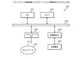
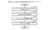
(実施の形態にかかるミラーパケット制御方法の一実施例)
図1は、実施の形態にかかるミラーパケット制御方法の一実施例を示す説明図である。図1において、ミラーパケット制御装置100は、VM(Virtual Machine)を動作させるコンピュータである。(An example of a Miller packet control method according to an embodiment)
FIG. 1 is an explanatory diagram showing an embodiment of the Miller Puckette control method according to the embodiment. In FIG. 1, the mirror
ミラーパケット制御装置100で動作するVMは、例えば、ポートミラーリングにより、第1VMからミラーパケットを送信される第2VMである。以下の説明では、第1VMを「ターゲットVM」と表記する場合がある。また、以下の説明では、第2VMを「モニタVM」と表記する場合がある。 The VM operating in the mirror
ここで、ポートミラーリングは、例えば、ターゲットVMを動作させるコンピュータが有する仮想スイッチにより実現される。例えば、仮想スイッチは、仮想スイッチからターゲットVMへのポートを通じて送受信されるパケットを複製したミラーパケットを、仮想スイッチからモニタVMへのポートを通じて転送する。 Here, port mirroring is realized, for example, by a virtual switch possessed by a computer that operates a target VM. For example, the virtual switch forwards a mirror packet that duplicates a packet sent and received from the virtual switch through the port to the target VM through the port from the virtual switch to the monitor VM.
しかしながら、モニタVMがライブマイグレーションを行った場合、モニタVMがミラーパケットを受信することができなくなることがある。ライブマイグレーションは、VMをコンピュータ間で移動させるマイグレーションの1種である。ライブマイグレーションは、VMを移動する際、VMが停止する時間の低減化を図る。 However, when the monitor VM performs live migration, the monitor VM may not be able to receive the mirror packet. Live migration is a type of migration that moves VMs between computers. Live migration aims to reduce the time that the VM is stopped when moving the VM.
例えば、モニタVMがライブマイグレーションを行った場合、仮想スイッチは、モニタVMが移動したことを検出することができない。このため、仮想スイッチは、モニタVMが移動した後も、移動前のモニタVMに通じるポートからミラーパケットを送信してしまい、ミラーパケットは、モニタVMが受信することができずに失われてしまう。また、モニタVMは、ミラーパケットが生成されたことを検出することができず、ミラーパケットについて再送要求することも困難である。 For example, if the monitor VM performs live migration, the virtual switch cannot detect that the monitor VM has moved. Therefore, even after the monitor VM has moved, the virtual switch sends a mirror packet from the port leading to the monitor VM before the move, and the mirror packet cannot be received by the monitor VM and is lost. .. Further, the monitor VM cannot detect that the mirror packet has been generated, and it is difficult to request retransmission of the mirror packet.
これに対し、仮想スイッチが、一定時間ごとに、モニタVMを動作させているコンピュータを調査し、ミラーパケットを送信するポートを更新する場合が考えられる。例えば、仮想スイッチが、一定時間ごとに、モニタVMへのミラーパケットをすべてのポートから送信し、ミラーパケットに対する応答を受信したポートを、モニタVMに通じるポートとして記憶する。 On the other hand, it is conceivable that the virtual switch investigates the computer operating the monitor VM at regular intervals and updates the port for transmitting the mirror packet. For example, the virtual switch sends a mirror packet to the monitor VM from all ports at regular intervals, and stores the port that receives the response to the mirror packet as a port leading to the monitor VM.
しかしながら、この場合であっても、モニタVMがミラーパケットを受信することができなくなることがある。例えば、モニタVMが移動してから、モニタVMを動作させているコンピュータを調査するまでの期間では、仮想スイッチは、移動前のモニタVMに通じるポートからミラーパケットを送信してしまう。また、モニタVMが移動しなくても、仮想スイッチが、一定時間ごとに、モニタVMを動作させているコンピュータを調査するため、処理負荷の増大化を招いてしまう。 However, even in this case, the monitor VM may not be able to receive the mirror packet. For example, in the period from the movement of the monitor VM to the investigation of the computer operating the monitor VM, the virtual switch sends a mirror packet from the port leading to the monitor VM before the movement. Further, even if the monitor VM does not move, the virtual switch investigates the computer operating the monitor VM at regular intervals, which causes an increase in the processing load.
このほか、仮想スイッチが、モニタVMがライブマイグレーションを行ったことに応じて、仮想基盤からL2ネットワークに流されるGARPパケットを検出した場合に、モニタVMが移動したことを検出するようにすることが考えられる。 In addition, the virtual switch may detect that the monitor VM has moved when it detects a ARP packet sent from the virtual infrastructure to the L2 network in response to the live migration of the monitor VM. Conceivable.
しかしながら、GARPパケットは、仮想スイッチに、モニタVMを動作させているコンピュータを調査させるためのパケットではない。そして、モニタVMとターゲットVMとが同じL2ネットワークに属していなければ、仮想スイッチは、GARPパケットを検出することができない。このため、仮想スイッチは、モニタVMが移動した後も、移動前のモニタVMに通じるポートからミラーパケットを送信してしまうことがある。 However, the ARP packet is not a packet for causing the virtual switch to investigate the computer running the monitor VM. Then, if the monitor VM and the target VM do not belong to the same L2 network, the virtual switch cannot detect the ARP packet. Therefore, the virtual switch may send a mirror packet from the port leading to the monitor VM before the movement even after the monitor VM has moved.
そこで、本実施の形態では、自装置に移動してきたモニタVMにミラーパケットを送信する送信元を特定し、特定した送信元に登録されたモニタVMに通じるポートの情報を削除させるミラーパケット制御方法について説明する。これによれば、本実施の形態は、モニタVMにミラーパケットを送信する送信元が、モニタVMに通じるポートの情報を更新するように仕向けて、ミラーパケットが失われることを防止することができる。 Therefore, in the present embodiment, a mirror packet control method is used in which a source for transmitting a mirror packet is specified to a monitor VM that has moved to the own device, and information on a port leading to the monitor VM registered in the specified source is deleted. Will be explained. According to this, in this embodiment, it is possible to prevent the mirror packet from being lost by inviting the source that sends the mirror packet to the monitor VM to update the information of the port leading to the monitor VM. ..
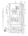
図1(a)の例では、ミラーパケット制御装置100と第1サーバ110と第2サーバ120とは、通信可能に接続されている。ミラーパケット制御装置100は、モニタVM102の識別情報と、モニタVM102にミラーパケットを送信する送信元の識別情報とを対応付けて表す第1対応情報を有する。第1対応情報は、例えば、図7に後述するモニタ管理テーブル700である。ミラーパケット制御装置100において、ホストOS(Operating System)nが実行されている。ホストOSnは、仮想スイッチを有する。仮想スイッチは、例えば、OVS(Open vSwitch)nである。仮想スイッチは、OVSでなくてもよい。 In the example of FIG. 1A, the Miller
また、第1サーバ110は、モニタVM102の識別情報と、自装置からモニタVM102に通じるポートの識別情報とを対応付けて表す第2対応情報を有する。第2対応情報は、例えば、図5に後述するミラーパケット用経路管理テーブル500である。第1サーバ110において、ホストOS1が実行されている。ホストOS1において、ターゲットVM101が実行されている。ホストOS1は、OVS1を有する。OVS1は、ターゲットVM101に対するパケットの送受信を制御する。 Further, the
OVS1は、例えば、ターゲットVM101に対して送受信されるパケットを複製したミラーパケットを、すべてのポートに対して出力する。そして、OVS1は、ミラーパケットに対する応答に基づいて、モニタVM102に通じるポートを特定し、第2対応情報を生成する。その後、OVS1は、生成した第2対応情報を参照し、ターゲットVM101に対して送受信されるパケットを複製したミラーパケットを、モニタVM102に通じるポートに出力する。 The OVS1 outputs, for example, a mirror packet that duplicates a packet transmitted / received to / from the target VM101 to all ports. Then, the
また、第2サーバ120は、ホストOS2を実行する。ホストOS2において、モニタVM102が実行されている。ホストOS2は、OVS2を有する。OVS2は、モニタVM102に対するパケットの送受信を制御する。次に、図1(b)の説明に移行し、モニタVM102がライブマイグレーションにより第2サーバ120から移動された場合について説明する。 Further, the
図1(b)の例では、モニタVM102が、ライブマイグレーションにより、第2サーバ120からミラーパケット制御装置100へ移動される。ここで、モニタVM102が移動した後、第2対応情報が更新されなければ、OVS1は、ターゲットVM101に対して送受信されるパケットを複製したミラーパケットを、第2サーバ120に通じるポートに出力してしまう可能性がある。このため、ミラーパケットは、モニタVM102に受信されずに失われてしまう。 In the example of FIG. 1 (b), the
そこで、ミラーパケット制御装置100において、OVSnは、他装置から自装置へのモニタVM102の移動完了の通知を検出したことに応じて、第1対応情報を参照し、自装置へ移動完了したモニタVM102にミラーパケットを送信する送信元を特定する。OVSnは、例えば、モニタVM102にミラーパケットを送信する送信元として第1サーバ110を特定する。 Therefore, in the Miller
そして、OVSnは、特定した送信元が有する第2対応情報を削除させる削除指示を、特定した送信元に送信する。OVSnは、第2対応情報の削除指示を、特定した第1サーバ110に送信する。これにより、OVSnは、モニタVM102の移動前後で、ミラーパケットを出力するポートが変化した可能性があり、ミラーパケットが失われる原因になりうる第2対応情報を削除させることができる。 Then, OVSn transmits a deletion instruction for deleting the second correspondence information possessed by the specified transmission source to the specified transmission source. OVSn sends a deletion instruction of the second correspondence information to the specified
一方で、第1サーバ110において、OVS1は、第2対応情報の削除指示を受け付けたことに応じて、第2対応情報を削除する。次に、OVS1は、第2対応情報の削除後、モニタVM102にミラーパケットを送信する際、すべてのポートに対してミラーパケットを出力する。そして、OVS1は、ミラーパケットに対する応答に基づいて、モニタVM102に通じるポートを特定し、第2対応情報を生成し直す。 On the other hand, in the
これにより、ミラーパケット制御装置100は、第1サーバ110が第2対応情報を生成し直すように仕向けることができる。このため、ミラーパケット制御装置100は、第1サーバ110のOVS1が、移動前のモニタVM102に通じるポートに対してミラーパケットを送信してしまうことを防止することができ、ミラーパケットが失われることを防止することができる。 As a result, the Miller
ここでは、ミラーパケット制御装置100が、ミラーパケットを受信する場合について説明したが、これに限らない。例えば、ミラーパケット制御装置100が、ミラーパケットを送信する場合があってもよい。具体的には、ミラーパケット制御装置100が、第1サーバ110としても動作可能である場合があってもよい。 Here, the case where the mirror
この場合、さらに、ミラーパケット制御装置100が、ミラーパケットを送信する際に、ミラーパケットを一旦退避させることが可能である場合があってもよい。ミラーパケットを一旦退避させることが可能である場合については、図27~図31を用いて動作例3に後述する。 In this case, further, the mirror
モニタVM102が、ターゲットVM101になる場合があってもよい。例えば、ターゲットVM101に送受信されるパケットを複製したミラーパケットを受信するモニタVM102が、他のモニタVM102に対応するターゲットVM101となる場合があってもよい。 The
(ポートミラーリングシステム200の一例)
次に、図2を用いて、図1に示したミラーパケット制御装置100を適用した、ポートミラーリングシステム200の一例について説明する。(Example of port mirroring system 200)
Next, an example of the
図2は、ポートミラーリングシステム200の一例を示す説明図である。図2において、ポートミラーリングシステム200は、複数のミラーパケット制御装置100と、管理装置201とを含む。 FIG. 2 is an explanatory diagram showing an example of the
ポートミラーリングシステム200において、それぞれのミラーパケット制御装置100と、管理装置201とは、有線または無線のネットワークを介して接続される。ネットワークは、例えば、LAN(Local Area Network)、WAN(Wide Area Network)、インターネットなどである。それぞれのミラーパケット制御装置100は、フルメッシュのオーバーレイネットワークを形成する。 In the
ミラーパケット制御装置100は、図1に示したように、自装置に移動してきたモニタVM102にミラーパケットを送信する送信元を特定し、特定した送信元に登録されたモニタVM102に通じるポートの情報を削除させるコンピュータである。また、ミラーパケット制御装置100は、ターゲットVM101を実行し、ポートミラーリングを実現し、図1に示した第1サーバ110として動作可能であってもよい。また、ミラーパケット制御装置100は、移動前のモニタVM102を実行し、図1に示した第2サーバ120として動作可能であってもよい。 As shown in FIG. 1, the mirror
それぞれのミラーパケット制御装置100が有する仮想スイッチは、例えば、VLAN(Virtual Local Area Network)を介して接続される。以下の説明では、それぞれのミラーパケット制御装置100を区別する場合には「ミラーパケット制御装置100-i」と表記する場合がある。iは、1~nの整数である。nは、ミラーパケット制御装置100の数である。ミラーパケット制御装置100は、例えば、サーバやPC(Personal Computer)である。 The virtual switch included in each Miller
管理装置201は、図9に後述する仮想マネージャ913やポートミラーマネージャ915を実行するコンピュータである。ポートミラーマネージャ915は、ターゲットVM101について入力されるパケットおよび出力されるパケットのうち、いずれのパケットを複製してモニタVM102に送信するかを設定し、ポートミラーリングを管理する。管理装置201は、例えば、サーバやPCである。ここでは、管理装置201が、ミラーパケット制御装置100とは異なる装置である場合について説明したが、これに限らない。例えば、管理装置201は、いずれかのミラーパケット制御装置100と一体であってもよい。 The
(ミラーパケット制御装置100のハードウェア構成例)
次に、図3を用いて、ミラーパケット制御装置100のハードウェア構成例について説明する。(Hardware configuration example of Miller packet control device 100)
Next, a hardware configuration example of the Miller
図3は、ミラーパケット制御装置100のハードウェア構成例を示すブロック図である。図3において、ミラーパケット制御装置100は、CPU(Central Processing Unit)301と、メモリ302と、ネットワークI/F(Interface)303と、記録媒体I/F304と、記録媒体305とを有する。また、各構成部は、バス300によってそれぞれ接続される。 FIG. 3 is a block diagram showing a hardware configuration example of the Miller
ここで、CPU301は、ミラーパケット制御装置100の全体の制御を司る。メモリ302は、例えば、ROM(Read Only Memory)、RAM(Random Access Memory)およびフラッシュROMなどを有する。具体的には、例えば、フラッシュROMやROMが各種プログラムを記憶し、RAMがCPU301のワークエリアとして使用される。メモリ302に記憶されるプログラムは、CPU301にロードされることで、コーディングされている処理をCPU301に実行させる。 Here, the
ネットワークI/F303は、通信回線を通じてネットワーク310に接続され、ネットワーク310を介して他のコンピュータに接続される。そして、ネットワークI/F303は、ネットワーク310と内部のインターフェースを司り、他のコンピュータからのデータの入出力を制御する。ネットワークI/F303には、例えば、モデムやLANアダプタなどを採用することができる。 The network I /
記録媒体I/F304は、CPU301の制御に従って記録媒体305に対するデータのリード/ライトを制御する。記録媒体I/F304は、例えば、ディスクドライブ、SSD(Solid State Drive)、USB(Universal Serial Bus)ポートなどである。記録媒体305は、記録媒体I/F304の制御で書き込まれたデータを記憶する不揮発メモリである。記録媒体305は、例えば、ディスク、半導体メモリ、USBメモリなどである。記録媒体305は、ミラーパケット制御装置100から着脱可能であってもよい。 The recording medium I /
ミラーパケット制御装置100は、上述した構成部のほか、例えば、キーボード、マウス、ディスプレイ、プリンタ、スキャナ、マイク、スピーカーなどを有してもよい。また、ミラーパケット制御装置100は、記録媒体I/F304や記録媒体305を複数有していてもよい。また、ミラーパケット制御装置100は、記録媒体I/F304や記録媒体305を有していなくてもよい。 The Miller
(管理装置201のハードウェア構成例)
ここで、管理装置201のハードウェア構成例については、図3に示したミラーパケット制御装置100のハードウェア構成例と同様であるため、説明を省略する。次に、ミラーパケット制御装置100や管理装置201が記憶する各種テーブルの記憶内容について説明する。(Hardware configuration example of management device 201)
Here, since the hardware configuration example of the
(トンネルポート管理テーブル400の記憶内容)
次に、図4を用いて、トンネルポート管理テーブル400の記憶内容の一例について説明する。トンネルポート管理テーブル400は、例えば、図3に示したミラーパケット制御装置100のメモリ302や記録媒体305の記憶領域により実現される。(Stored contents of tunnel port management table 400)
Next, an example of the stored contents of the tunnel port management table 400 will be described with reference to FIG. The tunnel port management table 400 is realized, for example, by the storage area of the
図4は、トンネルポート管理テーブル400の記憶内容の一例を示す説明図である。図4に示すように、トンネルポート管理テーブル400は、トンネルポートと、プロトコルと、ローカルIP(Internet Protocol)と、リモートIPとのフィールドを有する。トンネルポート管理テーブル400は、トンネルポートごとに各フィールドに情報を設定することにより、トンネルポート管理情報がレコードとして記憶される。 FIG. 4 is an explanatory diagram showing an example of the stored contents of the tunnel port management table 400. As shown in FIG. 4, the tunnel port management table 400 has fields for a tunnel port, a protocol, a local IP (Internet Protocol), and a remote IP. In the tunnel port management table 400, the tunnel port management information is stored as a record by setting information in each field for each tunnel port.
トンネルポートのフィールドには、トンネルポートを識別するIDが設定される。プロトコルのフィールドには、トンネルポートに対してパケットを出力する際に用いられるプロトコルを識別する名前が設定される。ローカルIPのフィールドには、トンネルポートに割り振られたローカルIPアドレスが設定される。リモートIPのフィールドには、トンネルポートに割り振られたリモートIPアドレスが設定される。 An ID that identifies the tunnel port is set in the field of the tunnel port. The protocol field is populated with a name that identifies the protocol used to output the packet to the tunnel port. The local IP address assigned to the tunnel port is set in the local IP field. The remote IP address assigned to the tunnel port is set in the remote IP field.
トンネルポート管理テーブル400は、ミラーパケット制御装置100によって生成される。ミラーパケット制御装置100は、トンネルポート管理テーブル400を用いることにより、トンネルポートに対してパケットを出力する際に、いずれのプロトコルを用いるかを特定可能にすることができる。 The tunnel port management table 400 is generated by the Miller
(ミラーパケット用経路管理テーブル500の記憶内容)
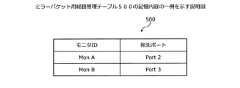
次に、図5を用いて、ミラーパケット用経路管理テーブル500の記憶内容の一例について説明する。ミラーパケット用経路管理テーブル500は、例えば、図3に示したミラーパケット制御装置100のメモリ302や記録媒体305の記憶領域により実現される。(Stored contents of the route management table 500 for mirror packets)
Next, an example of the stored contents of the Miller Puckette route management table 500 will be described with reference to FIG. The route management table 500 for mirror packets is realized, for example, by the storage area of the
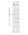
図5は、ミラーパケット用経路管理テーブル500の記憶内容の一例を示す説明図である。図5に示すように、ミラーパケット用経路管理テーブル500は、モニタIDと、宛先ポートとのフィールドを有する。ミラーパケット用経路管理テーブル500は、モニタVM102ごとに各フィールドに情報を設定することにより、ミラーパケット用経路管理情報がレコードとして記憶される。 FIG. 5 is an explanatory diagram showing an example of the stored contents of the Miller Puckette route management table 500. As shown in FIG. 5, the Miller Puckette route management table 500 has fields for a monitor ID and a destination port. In the mirror packet route management table 500, the mirror packet route management information is stored as a record by setting information in each field for each
モニタIDのフィールドには、モニタVM102を識別するIDが設定される。モニタVM102を識別するIDは、例えば、モニタVM102のポートを識別するIDである。宛先ポートのフィールドには、ミラーパケットを送信する仮想スイッチにおいてモニタVM102に通じる宛先ポートになるポートを識別するIDが設定される。 An ID that identifies the
ミラーパケット用経路管理テーブル500は、ミラーパケット制御装置100によって生成され更新される。ミラーパケット制御装置100は、ミラーパケット用経路管理テーブル500を用いることにより、ミラーパケットを生成した際、いずれのポートがモニタVM102に通じているかを特定することができる。このため、ミラーパケット制御装置100は、モニタVM102に通じるポートにミラーパケットを出力することができる。 The route management table 500 for mirror packets is generated and updated by the mirror
(ミラーポート管理テーブル600の記憶内容)
次に、図6を用いて、ミラーポート管理テーブル600の記憶内容の一例について説明する。ミラーポート管理テーブル600は、例えば、管理装置201の記憶領域により実現される。(Stored contents of mirror port management table 600)
Next, an example of the stored contents of the mirror port management table 600 will be described with reference to FIG. The mirror port management table 600 is realized, for example, by the storage area of the
図6は、ミラーポート管理テーブル600の記憶内容の一例を示す説明図である。図6に示すように、ミラーポート管理テーブル600は、IDと、名前と、ミラーポートIDと、ポートミラー方向と、モニタIDとのフィールドを有する。ミラーポート管理テーブル600は、ポートミラーリングによって複製されるパケットが流れるミラーポートごとに各フィールドに情報を設定することにより、ミラーポート管理情報がレコードとして記憶される。 FIG. 6 is an explanatory diagram showing an example of the stored contents of the mirror port management table 600. As shown in FIG. 6, the mirror port management table 600 has fields for an ID, a name, a mirror port ID, a port mirror direction, and a monitor ID. The mirror port management table 600 stores mirror port management information as a record by setting information in each field for each mirror port through which packets duplicated by port mirroring flow.
IDのフィールドには、レコードに割り振られたIDが設定される。名前のフィールドには、ポートミラーリングによって複製されるパケットが流れるミラーポートになるポートの名前が設定される。ミラーポートIDのフィールドには、ミラーポートを識別するIDが設定される。ポートミラー方向のフィールドには、ミラーポートをいずれの方向に流れるパケットを複製するかが設定される。モニタIDのフィールドには、ミラーパケットを受信するモニタVM102を識別するIDが設定される。 The ID assigned to the record is set in the ID field. The name field is populated with the name of the port that will be the mirror port through which packets replicated by port mirroring will flow. An ID that identifies the mirror port is set in the mirror port ID field. The field in the port mirror direction is set in which direction the packet flowing through the mirror port is to be duplicated. In the monitor ID field, an ID that identifies the
ミラーポート管理テーブル600は、管理装置201によって生成され更新される。管理装置201は、ミラーポート管理テーブル600を用いることにより、いずれのポートを流れるパケットを複製してミラーパケットを生成するかを特定し、いずれのモニタVM102にミラーパケットを送信するかを特定することができる。 The mirror port management table 600 is generated and updated by the
(モニタ管理テーブル700の記憶内容)
次に、図7を用いて、モニタ管理テーブル700の記憶内容の一例について説明する。モニタ管理テーブル700は、例えば、図3に示したミラーパケット制御装置100のメモリ302や記録媒体305の記憶領域により実現される。(Stored contents of monitor management table 700)
Next, an example of the stored contents of the monitor management table 700 will be described with reference to FIG. 7. The monitor management table 700 is realized, for example, by the storage area of the
図7は、モニタ管理テーブル700の記憶内容の一例を示す説明図である。図7に示すように、モニタ管理テーブル700は、IDと、名前と、ミラーポートIDと、ホストIDと、モニタIDとのフィールドを有する。モニタ管理テーブル700は、ポートミラーリングによって複製されるパケットが流れるミラーポートごとに各フィールドに情報を設定することにより、モニタ管理情報がレコードとして記憶される。 FIG. 7 is an explanatory diagram showing an example of the stored contents of the monitor management table 700. As shown in FIG. 7, the monitor management table 700 has fields for an ID, a name, a mirror port ID, a host ID, and a monitor ID. In the monitor management table 700, monitor management information is stored as a record by setting information in each field for each mirror port through which packets duplicated by port mirroring flow.
IDのフィールドには、レコードに割り振られたIDが設定される。名前のフィールドには、ポートミラーリングによって複製されるパケットが流れるミラーポートになるポートの名前が設定される。ミラーポートIDのフィールドには、ミラーポートを識別するIDが設定される。ホストIDのフィールドには、ミラーポートを有する演算装置を識別するIDが設定される。演算装置は、例えば、ミラーパケット制御装置100である。演算装置を識別するIDは、例えば、演算装置のホストOSを識別するIDである。モニタIDのフィールドには、ミラーパケットを受信するモニタVM102を識別するIDが設定される。 The ID assigned to the record is set in the ID field. The name field is populated with the name of the port that will be the mirror port through which packets replicated by port mirroring will flow. An ID that identifies the mirror port is set in the mirror port ID field. An ID that identifies an arithmetic unit having a mirror port is set in the host ID field. The arithmetic unit is, for example, the Miller
モニタ管理テーブル700は、ミラーパケット制御装置100によって生成され更新される。ミラーパケット制御装置100は、モニタ管理テーブル700を用いることにより、モニタVM102にミラーパケットを送信する送信元になる他のミラーパケット制御装置100を特定することができる。このため、ミラーパケット制御装置100は、ミラーパケット用経路管理テーブル500を更新することが好ましい他のミラーパケット制御装置100を特定することができる。 The monitor management table 700 is generated and updated by the Miller
(ミラーパケット制御装置100の機能的構成例)
次に、図8を用いて、ミラーパケット制御装置100の機能的構成例について説明する。(Example of functional configuration of Miller packet control device 100)
Next, a functional configuration example of the Miller
図8は、ミラーパケット制御装置100の機能的構成例を示すブロック図である。ミラーパケット制御装置100は、記憶部800を含む。ミラーパケット制御装置100は、取得部801と、第1検出部802と、特定部803と、第1送信部804とを含む。 FIG. 8 is a block diagram showing a functional configuration example of the Miller
ミラーパケット制御装置100は、更新部805と、第2送信部806とを含む。ミラーパケット制御装置100は、第2検出部807と、退避部808と、登録部809とを含む。ミラーパケット制御装置100は、出力部810を含む。 The Miller
記憶部800は、例えば、図3に示したメモリ302や記録媒体305などの記憶領域によって実現される。以下では、記憶部800が、ミラーパケット制御装置100に含まれる場合について説明するが、これに限らない。例えば、記憶部800が、ミラーパケット制御装置100とは異なる装置に含まれ、記憶部800の記憶内容がミラーパケット制御装置100から参照可能である場合があってもよい。 The
取得部801~出力部810は、制御部となる機能である。取得部801~出力部810は、具体的には、例えば、図3に示したメモリ302や記録媒体305などの記憶領域に記憶されたプログラムをCPU301に実行させることにより、または、ネットワークI/F303により、その機能を実現する。各機能部の処理結果は、例えば、図3に示したメモリ302や記録媒体305などの記憶領域に記憶される。 The
ミラーパケット制御装置100は、例えば、他装置からミラーパケットを送信されるVMが自装置に移動してきた場合、取得部801と、第1検出部802と、特定部803と、第1送信部804とによって動作する。以下では、他装置からミラーパケットを送信されるVMが自装置に移動してきた場合における、取得部801と、第1検出部802と、特定部803と、第1送信部804との動作について説明する。 In the mirror
記憶部800は、各機能部の処理に用いられる各種情報を記憶する。記憶部800は、例えば、第1対応情報を記憶する。第1対応情報は、VMの識別情報と、当該VMにミラーパケットを送信する送信元の識別情報とを対応付けて表す対応情報である。VMは、モニタVM102である。送信元は、ミラーポートを有する演算装置である。演算装置は、例えば、ミラーパケット制御装置100である。第1対応情報は、例えば、モニタVM102の識別情報と、モニタVM102にミラーパケットを送信する送信元になる演算装置の識別情報とを対応付けて表す。第1対応情報は、例えば、図7に示したモニタ管理テーブル700である。 The
記憶部800は、具体的には、他装置からミラーパケットを送信されるモニタVM102が自装置に移動してきた場合のために、特定部803によって用いられる図7に示したモニタ管理テーブル700を記憶する。これにより、記憶部800は、各機能部の処理に用いられる各種情報を、各機能部に参照可能にすることができる。 Specifically, the
第1検出部802は、他装置から自装置へのモニタVM102の移動完了の通知を検出する。通知は、例えば、GARP(Gratuitous Address Resolution Protocol)パケットである。第1検出部802は、例えば、仮想基盤からGARPパケットを受信する。 The
これにより、第1検出部802は、他装置から自装置にモニタVM102が移動してきたことを検出することができる。そして、第1検出部802は、自装置に移動してきたモニタVM102にミラーパケットを送信する送信元が、モニタVM102に通じるポートを正しく特定することができない状態である可能性があることを検出することができる。第1検出部802の動作は、具体的には、ポートミラーリングシステム200においては、図9に後述するライブマイグレーション完了検出部などによって実現される。 As a result, the
特定部803は、第1検出部802が他装置から自装置へのモニタVM102の移動完了の通知を検出したことに応じて、第1対応情報を参照し、自装置へ移動完了したモニタVM102にミラーパケットを送信する送信元を特定する。特定部803は、図7に示したモニタ管理テーブル700を参照し、自装置に移動してきたモニタVM102のポートを識別するモニタIDに対応付けられたホストIDを特定する。 The
これにより、特定部803は、自装置に移動してきたモニタVM102にミラーパケットを送信する、モニタVM102に通じるポートを正しく特定することができない状態である可能性がある送信元を特定することができる。特定部803の動作は、具体的には、ポートミラーリングシステム200においては、図9に後述する再学習通知パケット送信部などによって実現される。 As a result, the
第1送信部804は、特定部803が特定した送信元が有する第2対応情報の削除指示を、特定部803が特定した送信元に送信する。第2対応情報は、送信元からミラーパケットを送信されるモニタVM102の識別情報と、送信元からモニタVM102へのポートの識別情報とを対応付けて表す対応情報である。第2対応情報は、例えば、モニタVM102の識別情報と、自装置からモニタVM102に通じるポートの識別情報とを対応付けて表す。第2対応情報は、例えば、図5に示したミラーパケット用経路管理テーブル500である。削除指示は、第2対応情報を削除させる指示である。第1送信部804は、削除指示を、特定部803が特定したホストIDが示す他のミラーパケット制御装置100に送信する。 The
これにより、第1送信部804は、モニタVM102に通じるポートを正しく特定することができない状態である可能性がある送信元に、第2対応情報を削除させ、第2対応情報を生成し直すように仕向けることができる。このため、第1送信部804は、送信元において、移動前のモニタVM102に通じるポートに対してミラーパケットを送信してしまうことを防止することができ、ミラーパケットが失われることを防止することができる。 As a result, the
削除指示は、自装置に移動完了したモニタVM102の識別情報を含み、第2対応情報のうち、送信元から自装置に移動完了したモニタVM102へのポートの識別情報について削除させる指示であってもよい。これにより、第1送信部804は、送信元において第2対応情報を更新する際にかかる処理量の低減化を図ることができる。第1送信部804の動作は、具体的には、ポートミラーリングシステム200においては、図9に後述する再学習通知パケット送信部などによって実現される。 The deletion instruction includes the identification information of the monitor VM102 that has been moved to the own device, and even if it is an instruction to delete the identification information of the port from the source to the monitor VM102 that has been moved to the own device from the second correspondence information. good. As a result, the
また、ミラーパケット制御装置100は、自装置からミラーパケットを送信する場合、取得部801と、更新部805と、第2送信部806とによって動作する。以下では、自装置からミラーパケットを送信する場合における、取得部801と、更新部805と、第2送信部806との動作について説明する。 Further, when the Miller
記憶部800は、各機能部の処理に用いられる各種情報を記憶する。記憶部800は、例えば、第2対応情報を記憶する。記憶部800は、具体的には、自装置からミラーパケットを送信する場合のために、更新部805によって更新され、第2送信部806によって用いられる、図5に示したミラーパケット用経路管理テーブル500を記憶する。また、記憶部800は、具体的には、図4に示したトンネルポート管理テーブル400を記憶してもよい。これにより、記憶部800は、各機能部の処理に用いられる各種情報を、各機能部に参照可能にすることができる。 The
取得部801は、自装置が有する第2対応情報の削除指示を受け付ける。取得部801は、例えば、他のミラーパケット制御装置100の第1送信部804から送信された削除指示を受信する。これにより、取得部801は、自装置が、モニタVM102に通じるポートを正しく特定することができない状態である可能性があることを検出することができる。取得部801の動作は、具体的には、ポートミラーリングシステム200においては、図9に後述する経路管理テーブルフラッシュ部などによって実現される。 The
更新部805は、自装置が有する第2対応情報の削除指示を受け付けたことに応じて、第2対応情報を削除する。更新部805は、例えば、削除指示を受け付けたことに応じて、ミラーパケット用経路管理テーブル500を削除する。更新部805は、例えば、モニタVM102の識別情報を含む削除指示を受け付けたことに応じて、ミラーパケット用経路管理テーブル500のうち、削除指示に含まれるモニタVM102の識別情報に対応するレコードを削除してもよい。 The
これにより、更新部805は、モニタVM102に通じるポートを正しく特定することができない状態である可能性があるミラーパケット用経路管理テーブル500を一旦削除することができる。更新部805の動作は、具体的には、ポートミラーリングシステム200においては、図9に後述する経路管理テーブルフラッシュ部などによって実現される。 As a result, the
第2送信部806は、自装置からモニタVM102にミラーパケットを送信する際、第2対応情報を参照し、モニタVM102の識別情報に対応付けられた、自装置からモニタVM102へのポートの識別情報があるか否かを判定する。第2送信部806は、自装置からモニタVM102へのポートの識別情報がない場合、自装置から複数のポートのそれぞれのポートを通じてミラーパケットを送信する。 When the
これにより、第2送信部806は、いずれかのミラーパケット制御装置100に実行されているモニタVM102に、ミラーパケットが届くようにすることができ、モニタVM102から応答が返ってくるようにすることができる。第2送信部806の動作は、具体的には、ポートミラーリングシステム200においては、図9に後述するミラーパケット用経路学習部などによって実現される。 As a result, the
更新部805は、第2送信部806が送信したミラーパケットに対する応答に基づいて第2対応情報を更新する。更新部805は、例えば、ミラーパケットに対する応答を受信したポートを、モニタVM102に通じるポートとして設定し、ミラーパケット用経路管理テーブル500を更新する。 The
これにより、更新部805は、ミラーパケット用経路管理テーブル500を生成し直し、モニタVM102に通じるポートを正しく特定することができるようにすることができる。そして、更新部805は、移動前のモニタVM102に通じるポートに対してミラーパケットを送信してしまうことを防止することができ、ミラーパケットが失われることを防止することができる。更新部805の動作は、具体的には、ポートミラーリングシステム200においては、図9に後述するミラーパケット用経路学習部などによって実現される。 As a result, the
第2送信部806は、自装置からモニタVM102にミラーパケットを送信する際、第2対応情報を参照し、モニタVM102の識別情報に対応付けられた、自装置からモニタVM102へのポートの識別情報があるか否かを判定する。第2送信部806は、自装置からモニタVM102へのポートの識別情報がある場合、自装置からモニタVM102へのポートを通じてミラーパケットを送信する。 When the
これにより、第2送信部806は、いずれかのミラーパケット制御装置100に実行されているモニタVM102に、ミラーパケットが届くようにすることができる。第2送信部806の動作は、具体的には、ポートミラーリングシステム200においては、図9に後述するミラーパケット用経路学習部などによって実現される。 As a result, the
また、ミラーパケット制御装置100は、自装置からミラーパケットを送信する際に、ミラーパケットを一旦退避させておく場合、取得部801と、第2検出部807と、退避部808と、登録部809と、第2送信部806とによって動作する。以下では、自装置からミラーパケットを送信する際に、ミラーパケットを一旦退避させておく場合における、取得部801と、第2検出部807と、退避部808と、登録部809と、第2送信部806との動作について説明する。 Further, when the mirror
記憶部800は、例えば、自装置からミラーパケットを送信する際に、ミラーパケットを一旦退避させておく場合のために、退避部808および登録部809によって用いられる、図25および図26に後述する各種テーブルを記憶する。これにより、記憶部800は、各機能部の処理に用いられる各種情報を、各機能部に参照可能にすることができる。 The
第2検出部807は、第1VMについての入出力に用いられる入出力バッファに登録されたパケットを複製したミラーパケットが出力される第2VMの停止状態を検出する。第1VMは、仮想スイッチに接続され、パケットの入出力が行われるVMである。第1VMは、例えば、ターゲットVM101である。 The
入出力バッファとは、ターゲットVM101についてのパケットの入出力に用いられる記憶領域である。入出力バッファは、例えば、入力リングバッファと、出力リングバッファと、パケットバッファとの組み合わせである。入力リングバッファは、パケットの入力通知を記憶する記憶領域である。出力リングバッファは、パケットの出力通知を記憶する記憶領域である。パケットバッファは、入力または出力の対象になるパケットを記憶する記憶領域である。入力リングバッファと、出力リングバッファと、パケットバッファとについては、図27に後述する。 The input / output buffer is a storage area used for input / output of packets for the
第2VMとは、仮想スイッチに接続され、ミラーパケットが出力されるVMである。第2VMは、例えば、仮想スイッチに直接接続されていなくてもよい。第2VMは、仮想スイッチのいずれかのポートから通じる他の仮想スイッチに接続されてもよい。第2VMは、例えば、モニタVM102である。 The second VM is a VM that is connected to a virtual switch and outputs a mirror packet. The second VM may not be directly connected to the virtual switch, for example. The second VM may be connected to another virtual switch leading from any port of the virtual switch. The second VM is, for example, the
第2検出部807は、例えば、第2VMが動作中の演算装置から他の演算装置にライブマイグレーションを開始したことに応じて、第2VMの停止状態を検出する。演算装置は、例えば、ミラーパケット制御装置100である。第2検出部807は、具体的には、モニタVM102がライブマイグレーションを開始したとき、モニタVM102が停止状態になったことを検出する。第2検出部807は、具体的には、管理装置201からモニタVM102の状態を通知されることにより、モニタVM102が停止状態になったことを検出してもよい。第2検出部807は、具体的には、モニタVM102に対してポーリングを行うことにより、モニタVM102が停止状態になったことを検出してもよい。 The
第2検出部807は、例えば、第2VMが動作中の演算装置から他の演算装置にライブマイグレーションする場合において、動作中の演算装置から他の演算装置への第2VMに関する情報の転送量を監視してもよい。そして、第2検出部807は、転送量が閾値を下回ったことに応じて、第2VMの停止状態を検出する。これにより、第2検出部807は、モニタVM102が停止中であり、ミラーパケットをモニタVM102に送信すると、ミラーパケットが失われる可能性がある状態になったことを検出することができる。 The
第2検出部807は、第2VMの停止状態の解除を検出する。第2検出部807は、例えば、モニタVM102の停止状態の解除を検出する。第2検出部807は、具体的には、管理装置201からモニタVM102の状態を通知されることにより、モニタVM102が停止状態になったことを検出する。第2検出部807は、具体的には、モニタVM102に対してポーリングを行うことにより、モニタVM102の停止状態の解除を検出してもよい。 The
これにより、第2検出部807は、モニタVM102が動作中であり、ミラーパケットをモニタVM102に送信しても、ミラーパケットが失われない状態になったことを検出することができる。第2検出部807の動作は、具体的には、ポートミラーリングシステム200においては、図27に後述する割り込み設定部や割り込み解除部などによって実現される。 As a result, the
退避部808は、停止状態が検出されてから停止状態が解除されるまでの期間において第1VMについての入出力の対象となるパケットについては入出力バッファとは異なる退避バッファに蓄積しておく。退避部808は、例えば、入出力バッファに一旦登録されたパケットを、仮想スイッチで読み出して転送してしまう前に、あるいは、ターゲットVM101が読み出してしまう前に退避バッファに移動し、入出力バッファからは削除する。 The
退避部808は、仮想スイッチから第1VMに入力されるパケットについて複製しない状態に設定された場合には、第2VMの停止状態が検出されたことに応じて第1VMを停止してもよい。退避部808は、例えば、ターゲットVM101について入力されるパケットおよび出力されるパケットのうち、いずれのパケットを複製してモニタVM102に送信する設定であるかを判定する。そして、退避部808は、ターゲットVM101について入力されるパケットを複製しなくてよい設定であれば、停止状態が検出されてから停止状態が解除されるまでの期間においてターゲットVM101を停止する。 When the
この場合、退避部808は、停止状態が検出されてから停止状態が解除されるまでの期間において第1VMについての入出力の対象となるパケットについて退避バッファに蓄積しない。退避部808は、例えば、ターゲットVM101についての入出力の対象となるパケットを、退避バッファに蓄積せず、入出力バッファに登録する。 In this case, the
これにより、退避部808は、モニタVM102が停止状態である間、ターゲットVM101に対してパケットの入出力が行われることを防止することができ、モニタVM102にミラーパケットが送信されることを防止することができる。退避部808の動作は、具体的には、ポートミラーリングシステム200においては、図27に後述する割り込みハンドラなどによって実現される。 As a result, the
登録部809は、停止状態が解除されると、退避バッファに蓄積しておいたパケットを、入出力バッファに登録する。登録部809は、例えば、退避バッファに蓄積した順序で、退避バッファに蓄積しておいたパケットを、入出力バッファに登録する。 When the stop state is released, the
これにより、登録部809は、ターゲットVM101に対するパケットの入出力を再開させ、ターゲットVM101に対するパケットの入出力が再開したことに応じてモニタVM102へのミラーパケットの送信も再開させることができる。また、登録部809は、入出力の順番を変えずに、ターゲットVM101に対するパケットの入出力が行われるようにすることができる。登録部809の動作は、具体的には、ポートミラーリングシステム200においては、図27に後述するパケット処理部などによって実現される。 As a result, the
第2送信部806は、入出力バッファに登録したパケットについて第1VMに対して入出力を行うとともに、入出力バッファに登録したパケットを複製したミラーパケットを第2VMに出力する。第2送信部806は、例えば、入出力バッファに登録し直されたパケットについてターゲットVM101に対して入出力を行う。また、第2送信部806は、入出力バッファに登録し直されたパケットを複製したミラーパケットをモニタVM102に送信する。 The
これにより、第2送信部806は、モニタVM102の停止状態が解除された後は、ターゲットVM101に対して入出力バッファに登録し直されたパケットの入出力を行うことができる。そして、第2送信部806は、入出力バッファに登録し直されたパケットの入出力が行われたことに応じて、入出力バッファに登録し直されたパケットを複製したミラーパケットを、停止状態が解除されたモニタVM102に送信することができる。第2送信部806の動作は、具体的には、ポートミラーリングシステム200においては、図27に後述するミラーパケット生成部などによって実現される。 As a result, the
出力部810は、各機能部の処理結果を出力する。出力形式は、例えば、ディスプレイへの表示、プリンタへの印刷出力、ネットワークI/F303による外部装置への送信、または、メモリ302や記録媒体305などの記憶領域への記憶である。これにより、出力部810は、各機能部の処理結果を利用者に通知可能にし、ミラーパケット制御装置100の管理や運用、例えば、ミラーパケット制御装置100の設定値の更新などを支援することができる。このため、出力部810は、ミラーパケット制御装置100の利便性の向上を図ることができる。 The
ミラーパケット制御装置100は、取得部801と、第1検出部802と、特定部803と、第1送信部804とを含まない場合があってもよい。また、ミラーパケット制御装置100は、更新部805と、第2送信部806とを含まない場合があってもよい。また、ミラーパケット制御装置100は、第2検出部807と、退避部808と、登録部809とを含まない場合があってもよい。 The Miller
(ポートミラーリングシステム200のモジュール構成例)
次に、図9を用いて、図8に示した各機能部の動作を実現するためのポートミラーリングシステム200のモジュール構成例について説明する。(Module configuration example of port mirroring system 200)
Next, a module configuration example of the
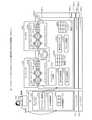
図9は、ポートミラーリングシステム200のモジュール構成例を示す説明図である。以下の説明では、それぞれのミラーパケット制御装置100-iが有するミラーパケット用経路管理テーブル500を区別する場合、「ミラーパケット用経路管理テーブル500-i」と表記する場合がある。同様に、それぞれのミラーパケット制御装置100-iが有するモニタ管理テーブル700を区別する場合、「モニタ管理テーブル700-i」と表記する場合がある。 FIG. 9 is an explanatory diagram showing an example of a module configuration of the
図9の例では、管理装置201のハードウェア910において、管理装置201のハイパーバイザ911が実行されている。管理装置201のハイパーバイザ911において、OS912が実行されている。OS912において、仮想マネージャ913が実行されている。仮想マネージャ913は、モニタ管理テーブル作成部914を含む。 In the example of FIG. 9, the
モニタ管理テーブル作成部914は、モニタVM902がライブマイグレーションされた後、仮想基盤に問い合わせ、仮想基盤からモニタVM902のポートを識別するモニタIDを取得する。モニタ管理テーブル作成部914は、ミラーポート管理テーブル600を参照し、取得したモニタIDと、モニタIDに対応するミラーポートIDとホストIDとを対応付けた、モニタ管理テーブル700に追加されるレコードを生成する。モニタ管理テーブル作成部914は、生成したレコードをモニタVM902が移動されるミラーパケット制御装置100に送信する。モニタ管理テーブル作成部914は、具体的には、図16に後述するモニタ管理テーブル作成処理を実行する。 After the monitor VM902 is live-migrated, the monitor management
管理装置201のOS912において、ポートミラーマネージャ915が実行されている。ポートミラーマネージャ915は、ミラーポート管理テーブル600を有する。ポートミラーマネージャ915は、ポートミラーリングを制御する。管理装置201のハイパーバイザ911はなくてもよい。 The
また、ミラーパケット制御装置100-iのハードウェア920-iにおいて、ミラーパケット制御装置100-iのハイパーバイザ921-iが実行されている。ミラーパケット制御装置100-iのハイパーバイザ921-iにおいて、ミラーパケット制御装置100-iのホストOS922-iが実行されている。ミラーパケット制御装置100-iのホストOS922-iにおいて、ターゲットVM901、または、モニタVM902が実行可能である。 Further, in the hardware 920-i of the mirror packet control device 100-i, the hypervisor 921-i of the mirror packet control device 100-i is executed. In the hypervisor 921-i of the mirror packet control device 100-i, the host OS 922-i of the mirror packet control device 100-i is executed. The target VM901 or the monitor VM902 can be executed in the host OS 922-i of the Miller packet control device 100-i.
ミラーパケット制御装置100-iのホストOS922-iは、仮想スイッチ923-iを含む。仮想スイッチ923-iは、ミラーパケット用経路学習部924-iと、ライブマイグレーション完了検出部925-iと、再学習通知パケット送信部926-iと、経路管理テーブルフラッシュ部927-iとを含む。仮想スイッチ923-iは、ミラーパケット用経路管理テーブル500-iと、モニタ管理テーブル700-iとを有する。 The host OS 922-i of the Miller Puckette control device 100-i includes a virtual switch 923-i. The virtual switch 923-i includes a route learning unit 924-i for mirror packets, a live migration completion detection unit 925-i, a relearning notification packet transmission unit 926-i, and a route management table flash unit 927-i. .. The virtual switch 923-i has a route management table 500-i for mirror packets and a monitor management table 700-i.
ミラーパケット用経路学習部924-iは、ターゲットVM901へのポートを通じてパケットが送受信されたことに応じて、パケットを複製したミラーパケットを生成する。ミラーパケット用経路学習部924-iは、ミラーパケットの宛先になるモニタVM902を示すモニタIDを取得可能であれば、モニタIDが示すポートを通じてミラーパケットを送信する。 The route learning unit 924-i for the mirror packet generates a mirror packet that duplicates the packet in response to the transmission / reception of the packet through the port to the target VM901. If the monitor ID indicating the monitor VM902 that is the destination of the mirror packet can be acquired, the route learning unit 924-i for the mirror packet transmits the mirror packet through the port indicated by the monitor ID.
ミラーパケット用経路学習部924-iは、ミラーパケットの宛先になるモニタVM902を示すモニタIDを取得可能でなければ、すべてのポートを通じてミラーパケットを送信する。ミラーパケット用経路学習部924-iは、送信したミラーパケットに対する返信パケットに基づいて、ミラーパケット用経路管理テーブル500-iを更新する。ミラーパケット用経路学習部924-iは、具体的には、図14および図15に後述するミラーパケット用経路学習処理を実行する。 The route learning unit 924-i for a mirror packet transmits a mirror packet through all ports unless it is possible to acquire a monitor ID indicating the monitor VM902 that is the destination of the mirror packet. The mirror packet route learning unit 924-i updates the mirror packet route management table 500-i based on the reply packet for the transmitted mirror packet. Specifically, the Miller Puckette route learning unit 924-i executes the Miller Puckette route learning process described later in FIGS. 14 and 15.
ライブマイグレーション完了検出部925-iは、GARPパケットを監視し、GARPパケットを検出したことに応じて、ライブマイグレーションが完了したことを検出する。ライブマイグレーション完了検出部925-iは、GARPパケットを検出したVMのポートを識別するIDをモニタIDとして設定する。ライブマイグレーション完了検出部925-iは、モニタIDでモニタ管理テーブル700-iを検索し、モニタIDに対応するミラーポートIDを取得する。ライブマイグレーション完了検出部925-iは、モニタIDと、ミラーポートIDとを、再学習通知パケット送信部926-iに指定して、図18に後述する再学習通知パケット送信処理を実行させる。 The live migration completion detection unit 925-i monitors the ARP packet and detects that the live migration is completed in response to the detection of the ARP packet. The live migration completion detection unit 925-i sets an ID for identifying the port of the VM that detected the ARP packet as a monitor ID. The live migration completion detection unit 925-i searches the monitor management table 700-i by the monitor ID and acquires the mirror port ID corresponding to the monitor ID. The live migration completion detection unit 925-i designates the monitor ID and the mirror port ID to the relearning notification packet transmission unit 926-i, and causes the relearning notification packet transmission process described later in FIG. 18 to be executed.
また、ライブマイグレーション完了検出部925-iは、GARPパケットを利用する方法とは異なる方法により、ライブマイグレーションが完了したことを検出してもよい。GARPパケットを利用する方法とは異なる方法については、具体的には、例えば、特開2014-182596号公報などを参照することができる。ライブマイグレーション完了検出部925-iは、具体的には、図17に後述するライブマイグレーション完了検出処理を実行する。 Further, the live migration completion detection unit 925-i may detect that the live migration has been completed by a method different from the method using the ARP packet. Specifically, for a method different from the method using a GARP packet, for example, Japanese Patent Application Laid-Open No. 2014-182596 can be referred to. Specifically, the live migration completion detection unit 925-i executes the live migration completion detection process described later in FIG.
再学習通知パケット送信部926-iは、ミラーポートIDでモニタ管理テーブル700-iを検索し、ミラーポートIDに対応するホストIDが示すホストOSに、再学習通知パケットを送信する。再学習通知パケット送信部926-iは、具体的には、図18に後述する再学習通知パケット送信処理を実行する。 The relearning notification packet transmission unit 926-i searches the monitor management table 700-i by the mirror port ID, and transmits the relearning notification packet to the host OS indicated by the host ID corresponding to the mirror port ID. Specifically, the relearning notification packet transmission unit 926-i executes the relearning notification packet transmission process described later in FIG.
経路管理テーブルフラッシュ部927-iは、再学習通知パケットを受信すると、ミラーパケット用経路管理テーブル500-iを初期化する。経路管理テーブルフラッシュ部927-iは、具体的には、図19に後述するミラーパケット用経路管理テーブル削除処理を実行する。 When the route management table flash unit 927-i receives the relearning notification packet, the route management table flash unit 927-i initializes the route management table 500-i for the mirror packet. Specifically, the route management table flush unit 927-i executes the mirror packet route management table deletion process described later in FIG.
図9において、(9-1)ポートミラーマネージャ915は、管理者903の操作入力によって、ライブマイグレーション指示を受け付けたとする。ポートミラーマネージャ915は、ライブマイグレーション指示を受け付けたため、モニタVM902を、ミラーパケット制御装置100-2からミラーパケット制御装置100-nへとライブマイグレーションする。ここで、図10~図13の説明に移行する。 In FIG. 9, it is assumed that (9-1) the
(ポートミラーリングシステム200の動作例1)
次に、図10~図13を用いて、ポートミラーリングシステム200の動作例1について説明する。(Operation example 1 of the port mirroring system 200)
Next, operation example 1 of the
図10~図13は、ポートミラーリングシステム200の動作例1を示す説明図である。仮想マネージャ913は、ライブマイグレーションが完了すると、GARPパケット1000を、モニタVM902が移動したミラーパケット制御装置100-nが属するL2ネットワークに対して送信する。ここで、図10の説明に移行し、GARPパケット1000のデータ構造について説明する。 10 to 13 are explanatory views showing an operation example 1 of the
図10に示すように、GARPパケット1000は、EtherヘッダとARPパケットを含む。Etherヘッダは、送信元MAC(Media Access Control)と、宛先MACとのフィールドを含む。送信元MACのフィールドには、送信元MACアドレスが設定される。宛先MACのフィールドには、宛先MACアドレスが設定される。 As shown in FIG. 10, the
ARPパケットは、宛先IPと、宛先MACと、送信元IPと、送信元MACと、制御情報とのフィールドを含む。宛先IPのフィールドには、ライブマイグレーションされたVMのIPアドレスが設定される。宛先MACのフィールドには、宛先MACアドレスが設定される。 The ARP packet includes fields of a destination IP, a destination MAC, a source IP, a source MAC, and control information. The IP address of the live-migrated VM is set in the destination IP field. The destination MAC address is set in the destination MAC field.
送信元IPのフィールドには、ライブマイグレーションされたVMのIPアドレスが設定される。宛先IPと送信元IPとのフィールドに、共通して、ライブマイグレーションされたVMのIPアドレスが設定されることにより、GARPパケット1000であることを示す。送信元MACのフィールドには、送信元MACアドレスが設定される。制御情報のフィールドには、制御情報が設定される。ここで、図11の説明に移行する。 The IP address of the live-migrated VM is set in the source IP field. By setting the IP address of the live-migrated VM in the fields of the destination IP and the source IP in common, it indicates that the ARP packet is 1000. The source MAC address is set in the source MAC field. Control information is set in the control information field. Here, the process proceeds to the description of FIG.
図11の例では、(11-1)管理装置201において、モニタ管理テーブル作成部914は、モニタVM902がライブマイグレーションされた後、モニタVM902のポートを識別するモニタIDを取得する。 In the example of FIG. 11, in (11-1)
次に、モニタ管理テーブル作成部914は、ミラーポート管理テーブル600を参照し、取得したモニタIDと、モニタIDに対応するミラーポートIDとホストIDとを対応付けた、モニタ管理テーブル700-nに追加されるレコードを生成する。そして、モニタ管理テーブル作成部914は、生成したレコードをモニタVM902が移動されたミラーパケット制御装置100-nに送信する。 Next, the monitor management
これにより、モニタ管理テーブル作成部914は、ミラーパケット制御装置100-nが有するモニタ管理テーブル700-nを最新の状態に更新することができ、モニタVM902に対するミラーパケットの送信元を正しく特定可能にすることができる。 As a result, the monitor management
(11-2)ミラーパケット制御装置100-nにおいて、ライブマイグレーション完了検出部925-nは、GARPパケット1000を監視し、GARPパケット1000を検出したVMのポートを識別するIDをモニタIDとして設定する。次に、ライブマイグレーション完了検出部925-nは、モニタIDでモニタ管理テーブル700-nを検索し、モニタIDに対応するミラーポートIDを取得する。そして、ライブマイグレーション完了検出部925-nは、モニタIDと、ミラーポートIDとを、再学習通知パケット送信部926-nに出力する。 (11-2) In the Miller packet control device 100-n, the live migration completion detection unit 925-n monitors the
これにより、ライブマイグレーション完了検出部925-nは、モニタVM902にミラーパケットを送信する送信元が、モニタVM902に通じるポートを正しく特定することができない状態である可能性があることを検出することができる。そして、ライブマイグレーション完了検出部925-nは、ミラーパケットの送信元において、ミラーパケット用経路管理テーブル500を削除させることが好ましいタイミングであることを、再学習通知パケット送信部926-nに通知することができる。 As a result, the live migration completion detection unit 925-n can detect that the source that sends the mirror packet to the monitor VM902 may not be able to correctly identify the port leading to the monitor VM902. can. Then, the live migration completion detection unit 925-n notifies the relearning notification packet transmission unit 926-n that it is a preferable timing to delete the mirror packet route management table 500 at the mirror packet transmission source. be able to.
(11-3)ミラーパケット制御装置100-nにおいて、再学習通知パケット送信部926-nは、通知されたミラーポートIDでモニタ管理テーブル700-nを検索し、ミラーポートIDに対応するホストIDが示すホストOSを取得する。そして、再学習通知パケット送信部926-nは、取得したホストOSに基づいて、モニタVM902にミラーパケットを送信するミラーパケット制御装置100-1に対して、図12に後述する再学習通知パケット1200を送信する。ここで、図12の説明に移行し、再学習通知パケット1200のデータ構造について説明する。 (11-3) In the mirror packet control device 100-n, the relearning notification packet transmission unit 926-n searches the monitor management table 700-n with the notified mirror port ID, and the host ID corresponding to the mirror port ID. Gets the host OS indicated by. Then, the relearning notification packet transmission unit 926-n sends the relearning
図12に示すように、再学習通知パケット1200は、ヘッダとペイロードとを含む。ヘッダは、Etherヘッダと、IP(Internet Protocol)ヘッダと、TCP(Transmission Control Protocol)ヘッダとのフィールドを含む。Etherヘッダのフィールドには、Etherヘッダの内容が設定される。IPヘッダのフィールドには、IPヘッダの内容が設定される。TCPヘッダのフィールドには、TCPヘッダの内容が設定される。ヘッダの内容は、通常のパケットと同様であってもよい。ペイロードには、識別子が設定される。識別子は、再学習通知パケット1200を、通常のパケットと区別可能にするための情報である。次に、図13の説明に移行する。 As shown in FIG. 12, the
図13の例では、(13-1)ミラーパケット制御装置100-1において、経路管理テーブルフラッシュ部927-1は、再学習通知パケット1200を受信する。経路管理テーブルフラッシュ部927-1は、再学習通知パケット1200を受信すると、再学習通知パケット1200のペイロードを参照し、再学習通知パケット1200であることを判定する。そして、経路管理テーブルフラッシュ部927-1は、ミラーパケット用経路管理テーブル500-1を削除する。 In the example of FIG. 13, in (13-1) Miller packet control device 100-1, the route management table flash unit 927-1 receives the relearning
これにより、経路管理テーブルフラッシュ部927-1は、モニタVM902に通じるポートを正しく特定することができない状態である可能性があるミラーパケット用経路管理テーブル500-1を一旦削除することができる。 As a result, the route management table flush unit 927-1 can temporarily delete the route management table 500-1 for the mirror packet, which may not be able to correctly specify the port leading to the monitor VM902.
(13-2)ミラーパケット制御装置100-1において、ミラーパケット用経路学習部924-1は、ターゲットVM901へのポートを通じてパケットが送受信されたことに応じて、パケットを複製したミラーパケットを生成する。次に、ミラーパケット用経路学習部924-1は、ミラーパケットを生成すると、ミラーパケット用経路管理テーブル500-1を参照する。 (13-2) In the Miller Puckette Control Device 100-1, the Miller Puckette Route Learning Unit 924-1 generates a Miller packet that duplicates the packet in response to the transmission and reception of the packet through the port to the target VM901. .. Next, when the mirror packet route learning unit 924-1 generates a mirror packet, the mirror packet route management table 500-1 is referred to.
ここで、ミラーパケット用経路学習部924-1は、ミラーパケット用経路管理テーブル500-1が削除されているため、すべてのポートを通じてミラーパケットを送信する。ミラーパケット用経路学習部924-1は、送信したミラーパケットに対する返信パケットに基づいて、ミラーパケット用経路管理テーブル500-1を更新する。 Here, the mirror packet route learning unit 924-1 transmits the mirror packet through all the ports because the mirror packet route management table 500-1 has been deleted. The mirror packet route learning unit 924-1 updates the mirror packet route management table 500-1 based on the reply packet for the transmitted mirror packet.
これにより、ミラーパケット用経路学習部924-1は、ミラーパケット用経路管理テーブル500-1を生成し直し、モニタVM902に通じるポートを正しく特定することができるようにすることができる。このように、ポートミラーリングシステム200では、ミラーパケット制御装置100-1が、移動前のモニタVM902に通じるポートに対してミラーパケットを送信してしまうことを防止することができ、ミラーパケットが失われることを防止することができる。 As a result, the Miller Puckette route learning unit 924-1 can regenerate the Miller Puckette route management table 500-1 so that the port leading to the monitor VM902 can be correctly specified. In this way, in the
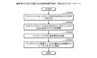
(動作例1におけるミラーパケット用経路学習処理手順)
次に、図14および図15を用いて、ミラーパケット制御装置100-iのミラーパケット用経路学習部924-iが実行する、動作例1におけるミラーパケット用経路学習処理手順の一例について説明する。(Miller packet route learning processing procedure in operation example 1)
Next, an example of the Miller Puckette route learning processing procedure in Operation Example 1 executed by the Miller Puckette route learning unit 924-i of the Miller Puckette control device 100-i will be described with reference to FIGS. 14 and 15.
図14および図15は、動作例1におけるミラーパケット用経路学習処理手順の一例を示すフローチャートである。図14において、ミラーパケット用経路学習部924-iは、ターゲットVM901へのポートを通じてパケットが送受信されたことに応じて、パケットを複製したミラーパケットを生成する(ステップS1401)。 14 and 15 are flowcharts showing an example of the Miller Puckette route learning processing procedure in Operation Example 1. In FIG. 14, the route learning unit 924-i for a mirror packet generates a mirror packet that duplicates the packet in response to the transmission / reception of the packet through the port to the target VM901 (step S1401).
次に、ミラーパケット用経路学習部924-iは、ミラーパケットの宛先になるモニタVM902を示すモニタIDを取得する(ステップS1402)。そして、ミラーパケット用経路学習部924-iは、ホストOSに問い合わせ、すべてのトンネルポートを特定する(ステップS1403)。 Next, the route learning unit 924-i for the mirror packet acquires a monitor ID indicating the monitor VM902 that is the destination of the mirror packet (step S1402). Then, the Miller Puckette route learning unit 924-i inquires of the host OS and identifies all the tunnel ports (step S1403).
次に、ミラーパケット用経路学習部924-iは、ミラーパケット用経路管理テーブル500-iに、取得したモニタIDに対応するレコードがあるか否かを判定する(ステップS1404)。ここで、レコードがある場合(ステップS1404:Yes)、ミラーパケット用経路学習部924-iは、取得したモニタIDに対応するレコードに設定された宛先ポートIDが示すトンネルポートに、生成したミラーパケットを送信する(ステップS1405)。そして、ミラーパケット用経路学習部924-iは、ミラーパケット用経路学習処理を終了する。 Next, the mirror packet route learning unit 924-i determines whether or not there is a record corresponding to the acquired monitor ID in the mirror packet route management table 500-i (step S1404). Here, when there is a record (step S1404: Yes), the route learning unit 924-i for the mirror packet has generated the mirror packet in the tunnel port indicated by the destination port ID set in the record corresponding to the acquired monitor ID. Is transmitted (step S1405). Then, the mirror packet route learning unit 924-i ends the mirror packet route learning process.
一方で、レコードがない場合(ステップS1404:No)、ミラーパケット用経路学習部924-iは、特定したすべてのトンネルポートに、生成したミラーパケットを送信する(ステップS1406)。そして、ミラーパケット用経路学習部924-iは、図15のステップS1501の処理に移行する。 On the other hand, when there is no record (step S1404: No), the route learning unit 924-i for the mirror packet transmits the generated mirror packet to all the specified tunnel ports (step S1406). Then, the route learning unit 924-i for the mirror packet shifts to the process of step S1501 of FIG.
図15において、ミラーパケット用経路学習部924-iは、送信したミラーパケットに対する返信パケットを受信する(ステップS1501)。次に、ミラーパケット用経路学習部924-iは、返信パケットに基づいて、返信パケットの送信元になるモニタVM902を示すモニタIDを取得する(ステップS1502)。そして、ミラーパケット用経路学習部924-iは、返信パケットを受信したトンネルポートを特定する(ステップS1503)。 In FIG. 15, the mirror packet route learning unit 924-i receives a reply packet for the transmitted mirror packet (step S1501). Next, the route learning unit 924-i for the mirror packet acquires a monitor ID indicating the monitor VM902 that is the source of the reply packet based on the reply packet (step S1502). Then, the route learning unit 924-i for the mirror packet identifies the tunnel port that received the reply packet (step S1503).
次に、ミラーパケット用経路学習部924-iは、取得したモニタIDと、特定したトンネルポートを示す宛先ポートIDとを対応付けて、ミラーパケット用経路管理テーブル500-iに記憶する(ステップS1504)。そして、ミラーパケット用経路学習部924-iは、ミラーパケット用経路学習処理を終了する。 Next, the route learning unit 924-i for the mirror packet associates the acquired monitor ID with the destination port ID indicating the specified tunnel port and stores it in the route management table 500-i for the mirror packet (step S1504). ). Then, the mirror packet route learning unit 924-i ends the mirror packet route learning process.
(動作例1におけるモニタ管理テーブル作成処理手順)
次に、図16を用いて、管理装置201のモニタ管理テーブル作成部914が実行する、動作例1におけるモニタ管理テーブル作成処理手順の一例について説明する。(Procedure for creating monitor management table in operation example 1)
Next, an example of the monitor management table creation processing procedure in the operation example 1 executed by the monitor management
図16は、動作例1におけるモニタ管理テーブル作成処理手順の一例を示すフローチャートである。図16において、モニタ管理テーブル作成部914は、VMIDと、移行元ホストと、移行先ホストとを指定する、ライブマイグレーション指示を待ち受ける(ステップS1601)。 FIG. 16 is a flowchart showing an example of the monitor management table creation processing procedure in the operation example 1. In FIG. 16, the monitor management
次に、モニタ管理テーブル作成部914は、ライブマイグレーション指示を受け付けたか否かを判定する(ステップS1602)。ここで、ライブマイグレーション指示を受け付けていない場合(ステップS1602:No)、モニタ管理テーブル作成部914は、ステップS1601の処理に戻る。 Next, the monitor management
一方で、ライブマイグレーション指示を受け付けた場合(ステップS1602:Yes)、モニタ管理テーブル作成部914は、ステップS1603の処理に移行する。ステップS1603では、モニタ管理テーブル作成部914は、VMIDが示すVMがライブマイグレーションされた後、仮想基盤に問い合わせ、仮想基盤からVMIDが示すVMのポートを識別するIDを取得する(ステップS1603)。 On the other hand, when the live migration instruction is received (step S1602: Yes), the monitor management
次に、モニタ管理テーブル作成部914は、ミラーポート管理テーブル600のレコードを選択する(ステップS1604)。そして、モニタ管理テーブル作成部914は、選択したレコードのモニタIDが、取得したIDに対応するか否かを判定する(ステップS1605)。ここで、モニタIDが取得したIDに対応しない場合(ステップS1605:No)、モニタ管理テーブル作成部914は、ステップS1608の処理に移行する。 Next, the monitor management
一方で、モニタIDが取得したIDに対応する場合(ステップS1605:Yes)、モニタ管理テーブル作成部914は、選択したレコードのミラーポートIDに対応するホストIDを取得する(ステップS1606)。次に、モニタ管理テーブル作成部914は、モニタIDと、ミラーポートIDと、ホストIDとを対応付けた、モニタ管理テーブル700に追加されるレコードを生成し、移行先ホストに送信する(ステップS1607)。そして、モニタ管理テーブル作成部914は、ステップS1608の処理に移行する。 On the other hand, when the monitor ID corresponds to the acquired ID (step S1605: Yes), the monitor management
ステップS1608では、モニタ管理テーブル作成部914は、ミラーポート管理テーブル600のすべてのレコードを選択したか否かを判定する(ステップS1608)。ここで、いずれかのレコードを選択していない場合(ステップS1608:No)、モニタ管理テーブル作成部914は、ステップS1604の処理に戻る。 In step S1608, the monitor management
一方で、すべてのレコードを選択している場合(ステップS1608:Yes)、モニタ管理テーブル作成部914は、モニタ管理テーブル作成処理を終了する。これにより、モニタ管理テーブル作成部914は、ポートミラーリングシステム200の最新の状態に対応するように、モニタ管理テーブル700を更新することができる。 On the other hand, when all the records are selected (step S1608: Yes), the monitor management
(動作例1におけるライブマイグレーション完了検出処理手順)
次に、図17を用いて、ミラーパケット制御装置100-iのライブマイグレーション完了検出部925-iが実行する、動作例1におけるライブマイグレーション完了検出処理手順の一例について説明する。(Live migration completion detection processing procedure in operation example 1)
Next, an example of the live migration completion detection processing procedure in the operation example 1 executed by the live migration completion detection unit 925-i of the Miller packet control device 100-i will be described with reference to FIG.
図17は、動作例1におけるライブマイグレーション完了検出処理手順の一例を示すフローチャートである。図17において、ライブマイグレーション完了検出部925-iは、GARPパケット1000を監視する(ステップS1701)。 FIG. 17 is a flowchart showing an example of the live migration completion detection processing procedure in the operation example 1. In FIG. 17, the live migration completion detection unit 925-i monitors the ARP packet 1000 (step S1701).
次に、ライブマイグレーション完了検出部925-iは、GARPパケット1000を検出したか否かを判定する(ステップS1702)。ここで、検出していない場合(ステップS1702:No)、ライブマイグレーション完了検出部925-iは、ステップS1701の処理に戻る。一方で、検出した場合(ステップS1702:Yes)、ライブマイグレーション完了検出部925-iは、GARPパケット1000を検出したVMのポートを識別するIDをモニタIDとして設定し、ステップS1703の処理に移行する。 Next, the live migration completion detection unit 925-i determines whether or not the
ステップS1703では、ライブマイグレーション完了検出部925-iは、モニタIDでモニタ管理テーブル700-iを検索し、モニタIDに対応するミラーポートIDを取得する(ステップS1703)。ここで、ライブマイグレーション完了検出部925-iは、ミラーポートIDを1以上取得したか否かを判定する(ステップS1704)。ミラーポートIDを取得していない場合(ステップS1704:No)、ライブマイグレーション完了検出部925-iは、ライブマイグレーション完了検出処理を終了する。 In step S1703, the live migration completion detection unit 925-i searches the monitor management table 700-i by the monitor ID and acquires the mirror port ID corresponding to the monitor ID (step S1703). Here, the live migration completion detection unit 925-i determines whether or not one or more mirror port IDs have been acquired (step S1704). If the mirror port ID has not been acquired (step S1704: No), the live migration completion detection unit 925-i ends the live migration completion detection process.
一方で、ミラーポートIDを1以上取得している場合(ステップS1704:Yes)、ライブマイグレーション完了検出部925-iは、取得した1以上のミラーポートIDのいずれかのミラーポートIDを選択する(ステップS1705)。 On the other hand, when one or more mirror port IDs are acquired (step S1704: Yes), the live migration completion detection unit 925-i selects one of the acquired mirror port IDs of one or more mirror port IDs (step S1704: Yes). Step S1705).
次に、ライブマイグレーション完了検出部925-iは、モニタIDと、選択したミラーポートIDとを指定して、図18に後述する再学習通知パケット送信処理を、再学習通知パケット送信部926-iに実行させる(ステップS1706)。 Next, the live migration completion detection unit 925-i specifies the monitor ID and the selected mirror port ID, and performs the relearning notification packet transmission process described later in FIG. 18 on the relearning notification packet transmission unit 926-i. To execute (step S1706).
そして、ライブマイグレーション完了検出部925-iは、すべてのミラーポートIDを選択したか否かを判定する(ステップS1707)。ここで、いずれかのミラーポートIDを選択していない場合(ステップS1707:No)、ライブマイグレーション完了検出部925-iは、ステップS1705の処理に戻る。 Then, the live migration completion detection unit 925-i determines whether or not all the mirror port IDs have been selected (step S1707). Here, if any of the mirror port IDs is not selected (step S1707: No), the live migration completion detection unit 925-i returns to the process of step S1705.
一方で、すべてのミラーポートIDを選択している場合(ステップS1707:Yes)、ライブマイグレーション完了検出部925-iは、モニタ管理テーブル700-iを削除する(ステップS1708)。そして、ライブマイグレーション完了検出部925-iは、ライブマイグレーション完了検出処理を終了する。 On the other hand, when all the mirror port IDs are selected (step S1707: Yes), the live migration completion detection unit 925-i deletes the monitor management table 700-i (step S1708). Then, the live migration completion detection unit 925-i ends the live migration completion detection process.
(動作例1における再学習通知パケット送信処理手順)
次に、図18を用いて、ミラーパケット制御装置100-iの再学習通知パケット送信部926-iが実行する、動作例1における再学習通知パケット送信処理手順の一例について説明する。(Re-learning notification packet transmission processing procedure in operation example 1)
Next, an example of the relearning notification packet transmission processing procedure in the operation example 1 executed by the relearning notification packet transmission unit 926-i of the Miller packet control device 100-i will be described with reference to FIG.
図18は、動作例1における再学習通知パケット送信処理手順の一例を示すフローチャートである。図18において、再学習通知パケット送信部926-iは、ミラーポートIDでモニタ管理テーブル700-iを検索し、ミラーポートIDに対応するホストIDを取得する(ステップS1801)。 FIG. 18 is a flowchart showing an example of the relearning notification packet transmission processing procedure in the operation example 1. In FIG. 18, the relearning notification packet transmission unit 926-i searches the monitor management table 700-i by the mirror port ID and acquires the host ID corresponding to the mirror port ID (step S1801).
次に、再学習通知パケット送信部926-iは、再学習通知パケット1200を生成する(ステップS1802)。そして、再学習通知パケット送信部926-iは、取得したホストIDが示すホストOSに、生成した再学習通知パケット1200を送信する(ステップS1803)。 Next, the relearning notification packet transmission unit 926-i generates the relearning notification packet 1200 (step S1802). Then, the relearning notification packet transmission unit 926-i transmits the generated relearning
次に、再学習通知パケット送信部926-iは、取得したホストIDが示すホストOSからAckを受信する(ステップS1804)。そして、再学習通知パケット送信部926-iは、再学習通知パケット送信処理を終了する。 Next, the relearning notification packet transmission unit 926-i receives Ac from the host OS indicated by the acquired host ID (step S1804). Then, the relearning notification packet transmission unit 926-i ends the relearning notification packet transmission process.
(動作例1におけるミラーパケット用経路管理テーブル削除処理手順)
次に、図19を用いて、ミラーパケット制御装置100-iの経路管理テーブルフラッシュ部927-iが実行する、動作例1におけるミラーパケット用経路管理テーブル削除処理手順の一例について説明する。(Procedure for deleting the route management table for mirror packets in operation example 1)
Next, an example of the procedure for deleting the route management table for mirror packets in the operation example 1 executed by the route management table flash unit 927-i of the mirror packet control device 100-i will be described with reference to FIG.
図19は、動作例1におけるミラーパケット用経路管理テーブル削除処理手順の一例を示すフローチャートである。図19において、経路管理テーブルフラッシュ部927-iは、再学習通知パケット1200を待ち受ける(ステップS1901)。 FIG. 19 is a flowchart showing an example of the procedure for deleting the route management table for mirror packets in the operation example 1. In FIG. 19, the route management table flash unit 927-i waits for the relearning notification packet 1200 (step S1901).
次に、経路管理テーブルフラッシュ部927-iは、再学習通知パケット1200を受信したか否かを判定する(ステップS1902)。ここで、再学習通知パケット1200を受信していない場合(ステップS1902:No)、経路管理テーブルフラッシュ部927-iは、ステップS1901の処理に戻る。 Next, the route management table flash unit 927-i determines whether or not the relearning
一方で、再学習通知パケット1200を受信している場合(ステップS1902:Yes)、経路管理テーブルフラッシュ部927-iは、ミラーパケット用経路管理テーブル500-iを初期化する(ステップS1903)。次に、経路管理テーブルフラッシュ部927-iは、Ackを返信する(ステップS1904)。そして、経路管理テーブルフラッシュ部927-iは、ミラーパケット用経路管理テーブル削除処理を終了する。 On the other hand, when the relearning
(ポートミラーリングシステム200の動作例2)
次に、図20および図21を用いて、ポートミラーリングシステム200の動作例2について説明する。動作例1では、ミラーパケット制御装置100が、削除指示を受け付けたことに応じて、ミラーポート用経路管理テーブル全体を削除する場合について説明した。(Operation example 2 of the port mirroring system 200)
Next, operation example 2 of the
これに対し、動作例2では、削除指示がモニタIDを含み、ミラーパケット制御装置100が、削除指示を受け付けたことに応じて、ミラーポート用経路管理テーブルのいずれかのレコードを削除する場合について説明する。ここで、図20および図21の説明に移行する。 On the other hand, in the operation example 2, the deletion instruction includes the monitor ID, and the mirror
図20および図21は、ポートミラーリングシステム200の動作例2を示す説明図である。図20の例では、ミラーパケット制御装置100-nは、動作例1の(11-1)、(11-2)と同様に動作する。次に、ミラーパケット制御装置100-nは、動作例1の(11-3)に代わり、下記のように動作する。 20 and 21 are explanatory views showing an operation example 2 of the
(20-1)ミラーパケット制御装置100-nにおいて、再学習通知パケット送信部926-nは、通知されたミラーポートIDでモニタ管理テーブル700-nを検索し、ミラーポートIDに対応するホストIDが示すホストOSを取得する。次に、再学習通知パケット送信部926-nは、モニタVM902に対応するモニタIDを含むように、図21に後述する再学習通知パケット2100を生成する。 (20-1) In the mirror packet control device 100-n, the relearning notification packet transmission unit 926-n searches the monitor management table 700-n with the notified mirror port ID, and the host ID corresponding to the mirror port ID. Gets the host OS indicated by. Next, the relearning notification packet transmission unit 926-n generates the relearning
そして、再学習通知パケット送信部926-nは、取得したホストOSに基づいて、モニタVM902にミラーパケットを送信するミラーパケット制御装置100-1に対して、生成した再学習通知パケット2100を送信する。ここで、図21の説明に移行し、再学習通知パケット2100のデータ構造について説明する。 Then, the relearning notification packet transmission unit 926-n transmits the generated relearning
図21に示すように、再学習通知パケット2100は、ヘッダとペイロードとを含む。ヘッダの内容は、動作例1と同様である。ペイロードは、識別子と、モニタIDとのフィールドを含む。識別子は、再学習通知パケット2100を、通常のパケットと区別可能にするための情報である。モニタIDは、ライブマイグレーションされたモニタVM902に対応するモニタIDである。 As shown in FIG. 21, the
一方で、ミラーパケット制御装置100-1は、動作例1の(13-1)と(13-2)とに代わり、下記のように動作する。 On the other hand, the Miller Puckette control device 100-1 operates as follows instead of (13-1) and (13-2) of the operation example 1.
ミラーパケット制御装置100-1において、経路管理テーブルフラッシュ部927-1は、再学習通知パケット2100を受信すると、再学習通知パケット2100のペイロードを参照し、再学習通知パケット2100であることを判定する。そして、経路管理テーブルフラッシュ部927-1は、再学習通知パケット2100からモニタIDを取得し、ミラーパケット用経路管理テーブル500-1のうち、取得したモニタIDに対応するレコードを削除する。 In the Miller packet control device 100-1, when the route management table flash unit 927-1 receives the relearning
これにより、経路管理テーブルフラッシュ部927-1は、ミラーパケット用経路管理テーブル500-1のうち、削除しなくてもよいレコードについては削除しないようにすることができる。 As a result, the route management table flush unit 927-1 can prevent the mirror packet route management table 500-1 from not deleting the records that do not need to be deleted.
ミラーパケット制御装置100-1において、ミラーパケット用経路学習部924-1は、ターゲットVM901へのポートを通じてパケットが送受信されたことに応じて、パケットを複製したミラーパケットを生成する。次に、ミラーパケット用経路学習部924-1は、ミラーパケットを生成すると、ミラーパケット用経路管理テーブル500-1を参照する。 In the mirror packet control device 100-1, the route learning unit 924-1 for a mirror packet generates a mirror packet that duplicates the packet in response to the transmission / reception of the packet through the port to the target VM901. Next, when the mirror packet route learning unit 924-1 generates a mirror packet, the mirror packet route management table 500-1 is referred to.
ここで、ミラーパケット用経路学習部924-1は、ミラーパケット用経路管理テーブル500-1に、モニタVM902に対応するレコードがないため、すべてのポートを通じてミラーパケットを送信する。ミラーパケット用経路学習部924-1は、送信したミラーパケットに対する返信パケットに基づいて、ミラーパケット用経路管理テーブル500-1を更新する。 Here, since the mirror packet route learning unit 924-1 does not have a record corresponding to the monitor VM902 in the mirror packet route management table 500-1, the mirror packet is transmitted through all the ports. The mirror packet route learning unit 924-1 updates the mirror packet route management table 500-1 based on the reply packet for the transmitted mirror packet.
これにより、ミラーパケット用経路学習部924-1は、ミラーパケット用経路管理テーブル500-1のうち、生成し直すことになるレコードの数の増大化を抑制することができ、処理量の低減化を図ることができる。 As a result, the Miller Puckette route learning unit 924-1 can suppress an increase in the number of records to be regenerated in the Miller Puckette route management table 500-1, and reduce the processing amount. Can be planned.
(動作例2における再学習通知パケット送信処理手順)
次に、図22を用いて、動作例2における再学習通知パケット送信処理手順の一例について説明する。(Re-learning notification packet transmission processing procedure in operation example 2)
Next, an example of the relearning notification packet transmission processing procedure in the operation example 2 will be described with reference to FIG. 22.
図22は、動作例2における再学習通知パケット送信処理手順の一例を示すフローチャートである。図22において、再学習通知パケット送信部926-iは、ミラーポートIDでモニタ管理テーブル700-iを検索し、ミラーポートIDに対応するホストIDを取得する(ステップS2201)。 FIG. 22 is a flowchart showing an example of the relearning notification packet transmission processing procedure in the operation example 2. In FIG. 22, the relearning notification packet transmission unit 926-i searches the monitor management table 700-i by the mirror port ID and acquires the host ID corresponding to the mirror port ID (step S2201).
次に、再学習通知パケット送信部926-iは、再学習通知パケットを生成する(ステップS2202)。ここで、再学習通知パケット送信部926-iは、再学習通知パケットのペイロードに、モニタIDを埋め込む(ステップS2203)。そして、再学習通知パケット送信部926-iは、取得したホストIDが示すホストOSに、生成した再学習通知パケットを送信する(ステップS2204)。 Next, the relearning notification packet transmission unit 926-i generates a relearning notification packet (step S2202). Here, the relearning notification packet transmission unit 926-i embeds the monitor ID in the payload of the relearning notification packet (step S2203). Then, the relearning notification packet transmission unit 926-i transmits the generated relearning notification packet to the host OS indicated by the acquired host ID (step S2204).
次に、再学習通知パケット送信部926-iは、取得したホストIDが示すホストOSからAckを受信する(ステップS2205)。そして、再学習通知パケット送信部926-iは、再学習通知パケット送信処理を終了する。 Next, the relearning notification packet transmission unit 926-i receives Ac from the host OS indicated by the acquired host ID (step S2205). Then, the relearning notification packet transmission unit 926-i ends the relearning notification packet transmission process.
(動作例2におけるミラーパケット用経路管理テーブル削除処理手順)
次に、図23を用いて、動作例2におけるミラーパケット用経路管理テーブル削除処理手順の一例について説明する。(Procedure for deleting the route management table for mirror packets in operation example 2)
Next, an example of the procedure for deleting the route management table for mirror packets in the operation example 2 will be described with reference to FIG. 23.
図23は、動作例2におけるミラーパケット用経路管理テーブル削除処理手順の一例を示すフローチャートである。図23において、経路管理テーブルフラッシュ部927-iは、再学習通知パケットを待ち受ける(ステップS2301)。 FIG. 23 is a flowchart showing an example of the procedure for deleting the route management table for mirror packets in the operation example 2. In FIG. 23, the route management table flash unit 927-i waits for the relearning notification packet (step S2301).
次に、経路管理テーブルフラッシュ部927-iは、再学習通知パケットを受信したか否かを判定する(ステップS2302)。ここで、再学習通知パケットを受信していない場合(ステップS2302:No)、経路管理テーブルフラッシュ部927-iは、ステップS2301の処理に戻る。 Next, the route management table flash unit 927-i determines whether or not the relearning notification packet has been received (step S2302). Here, when the relearning notification packet is not received (step S2302: No), the route management table flush unit 927-i returns to the process of step S2301.
一方で、再学習通知パケットを受信している場合(ステップS2302:Yes)、経路管理テーブルフラッシュ部927-iは、再学習通知パケットのペイロードからモニタIDを取得する(ステップS2303)。 On the other hand, when the relearning notification packet is received (step S2302: Yes), the route management table flash unit 927-i acquires the monitor ID from the payload of the relearning notification packet (step S2303).
次に、経路管理テーブルフラッシュ部927-iは、ミラーパケット用経路管理テーブル500-iのうち、取得したモニタIDに対応するレコードを削除する(ステップS2304)。次に、経路管理テーブルフラッシュ部927-iは、Ackを返信する(ステップS2305)。そして、経路管理テーブルフラッシュ部927-iは、ミラーパケット用経路管理テーブル削除処理を終了する。 Next, the route management table flush unit 927-i deletes the record corresponding to the acquired monitor ID in the route management table 500-i for the mirror packet (step S2304). Next, the route management table flash unit 927-i returns Ac (step S2305). Then, the route management table flush unit 927-i ends the process of deleting the route management table for the mirror packet.
(ポートミラーリングシステム200の動作例3)
次に、図24~図31を用いて、ポートミラーリングシステム200の動作例3について説明する。動作例1では、ミラーパケット制御装置100が、ターゲットVM901に対してパケットが送受信されたことに応じて、ミラーパケットを生成してモニタVM902に送信する場合について説明した。(Operation example 3 of the port mirroring system 200)
Next, operation example 3 of the
これに対し、動作例3では、ミラーパケット制御装置100が、モニタVM902が停止状態であるか否かに応じて、ミラーパケットを一旦退避させることが可能である場合について説明する。 On the other hand, in the operation example 3, the case where the mirror
例えば、モニタVM902はライブマイグレーションされる際などに一時的に停止することがある。このため、モニタVM902の停止中にターゲットVM901が送信または受信したパケットを複製したミラーパケットは、モニタVM902が受信することができずに失われてしまう。また、モニタVM902は、ミラーパケットについて再送要求することも困難である。そこで、動作例3では、モニタVM902の停止中にミラーパケットが送信されることを防止することにより、ミラーパケットが失われる確率を低減する。 For example, the monitor VM902 may be temporarily stopped when it is live-migrated. Therefore, the mirror packet that duplicates the packet transmitted or received by the target VM901 while the monitor VM902 is stopped cannot be received by the monitor VM902 and is lost. It is also difficult for the monitor VM902 to request retransmission of the mirror packet. Therefore, in the operation example 3, the probability that the mirror packet is lost is reduced by preventing the mirror packet from being transmitted while the monitor VM902 is stopped.
動作例3では、管理装置201は、図24に後述するVM状態管理テーブル2400を記憶し、ミラーパケット制御装置100は、図25および図26に後述する各種テーブルを記憶する。ここで、図24~図26の説明に移行する。 In operation example 3, the
(VM状態管理テーブル2400の記憶内容)
次に、図24を用いて、VM状態管理テーブル2400の記憶内容の一例について説明する。VM状態管理テーブル2400は、例えば、管理装置201の記憶領域により実現される。(Stored contents of VM state management table 2400)
Next, an example of the stored contents of the VM state management table 2400 will be described with reference to FIG. 24. The VM state management table 2400 is realized, for example, by the storage area of the
図24は、VM状態管理テーブル2400の記憶内容の一例を示す説明図である。図24に示すように、VM状態管理テーブル2400は、VMIDと、ホストIDと、状態とのフィールドを有する。VM状態管理テーブル2400は、VMごとに各フィールドに情報を設定することにより、VM状態管理情報がレコードとして記憶される。 FIG. 24 is an explanatory diagram showing an example of the stored contents of the VM state management table 2400. As shown in FIG. 24, the VM state management table 2400 has fields for VMID, host ID, and state. In the VM state management table 2400, the VM state management information is stored as a record by setting information in each field for each VM.
VMIDのフィールドには、VMを一意に識別する情報であるVMIDが設定される。ホストIDのフィールドには、ホストOSを一意に識別する情報であるホストIDが設定される。状態のフィールドには、VMの状態が設定される。VMの状態は、例えば、VMが動作中であれば「ランニング(RUNNING)」であり、VMが停止中であれば「サスペンド(SUSPENDED)」である。 In the VMID field, VMID, which is information that uniquely identifies the VM, is set. In the host ID field, the host ID, which is information that uniquely identifies the host OS, is set. The VM state is set in the state field. The state of the VM is, for example, "RUNNING" when the VM is in operation and "SUSPENDED" when the VM is stopped.
VM状態管理テーブル2400は、管理装置201によって生成され更新される。管理装置201は、VM状態管理テーブル2400を用いることにより、それぞれのミラーパケット制御装置100におけるVMの状態を管理することができる。 The VM state management table 2400 is generated and updated by the
そして、管理装置201は、VM状態管理テーブル2400を参照することにより、ターゲットVM901を実行中であるミラーパケット制御装置100に、モニタVM902の状態がサスペンドになったことを通知することができる。また、管理装置201は、VM状態管理テーブル2400を参照することにより、ターゲットVM901を実行中であるミラーパケット制御装置100に、モニタVM902の状態がサスペンドからランニングに戻ったことを通知することができる。 Then, by referring to the VM state management table 2400, the
(リングバッファ管理テーブル2500の記憶内容)
次に、図25を用いて、リングバッファ管理テーブル2500の記憶内容の一例について説明する。リングバッファ管理テーブル2500は、例えば、図3に示したミラーパケット制御装置100のメモリ302や記録媒体305の記憶領域により実現される。(Stored contents of ring buffer management table 2500)
Next, an example of the stored contents of the ring buffer management table 2500 will be described with reference to FIG. 25. The ring buffer management table 2500 is realized, for example, by the storage area of the
ここで、リングバッファとは、いずれかのVMについてのパケットの入出力に用いられる記憶領域である。リングバッファは、例えば、入出力バッファに対応し、入出力バッファの一部となる記憶領域である。パケットの入力に用いられる入力リングバッファと、パケットの出力に用いられる出力リングバッファとが別々にあってもよい。 Here, the ring buffer is a storage area used for input / output of a packet for any VM. The ring buffer is, for example, a storage area corresponding to an input / output buffer and being a part of the input / output buffer. The input ring buffer used to input the packet and the output ring buffer used to output the packet may be separate.
図25は、リングバッファ管理テーブル2500の記憶内容の一例を示す説明図である。図25に示すように、リングバッファ管理テーブル2500は、VMIDと、Guest Addrと、Host Addrと、リングバッファサイズと、割り込み状態とのフィールドを有する。リングバッファ管理テーブル2500は、VMごとに各フィールドに情報を設定することにより、リングバッファ管理情報がレコードとして記憶される。 FIG. 25 is an explanatory diagram showing an example of the stored contents of the ring buffer management table 2500. As shown in FIG. 25, the ring buffer management table 2500 has fields for VMID, Guest Addr, Host Addr, ring buffer size, and interrupt state. In the ring buffer management table 2500, the ring buffer management information is stored as a record by setting information in each field for each VM.
VMIDのフィールドには、ゲストOSとなるVMを一意に識別する情報であるVMIDが設定される。Guest Addrのフィールドには、ゲストOSとなるVMがリングバッファを識別するためのアドレスであるGuest Addrが設定される。Guest Addrのフィールドには、パケットの入力に用いられる入力リングバッファと、パケットの出力に用いられる出力リングバッファとが別々にある場合には、それぞれのリングバッファに対応するGuest Addrが設定されてもよい。 In the VMID field, VMID, which is information that uniquely identifies the VM that is the guest OS, is set. In the field of Guest Addr, Guest Addr, which is an address for the VM serving as the guest OS to identify the ring buffer, is set. If the input ring buffer used for inputting the packet and the output ring buffer used for outputting the packet are separately set in the Guest Addr field, even if the Guest Addr corresponding to each ring buffer is set. good.
Host Addrのフィールドには、ホストOSがリングバッファを識別するためのアドレスであるHost Addrが設定される。Host Addrのフィールドには、パケットの入力に用いられる入力リングバッファと、パケットの出力に用いられる出力リングバッファとが別々にある場合には、それぞれのリングバッファに対応するHost Addrが設定されてもよい。 In the field of HostAddr, HostAddr, which is an address for the host OS to identify the ring buffer, is set. If the input ring buffer used for packet input and the output ring buffer used for packet output are separate in the Host Addr field, even if the Host Addr corresponding to each ring buffer is set. good.
リングバッファサイズのフィールドには、ゲストOSとなるVMについてのリングバッファのサイズが設定される。リングバッファサイズのフィールドには、パケットの入力に用いられる入力リングバッファと、パケットの出力に用いられる出力リングバッファとが別々にある場合には、それぞれのリングバッファのサイズが設定されてもよい。割り込み状態のフィールドには、ゲストOSとなるVMについてのパケットの入出力に対して割り込みを行う状態であるか否かを示すフラグが設定される。割り込み状態は、例えば、割り込みを行う状態であれば「オン(ON)」であり、割り込みを行わない状態であれば「オフ(OFF)」である。 In the ring buffer size field, the size of the ring buffer for the VM that is the guest OS is set. If the input ring buffer used for inputting the packet and the output ring buffer used for outputting the packet are separately set in the ring buffer size field, the size of each ring buffer may be set. In the interrupt state field, a flag is set to indicate whether or not an interrupt is performed for the input / output of the packet for the VM that is the guest OS. The interrupt state is, for example, "ON" when an interrupt is performed, and "OFF" when an interrupt is not performed.
リングバッファ管理テーブル2500は、ミラーパケット制御装置100によって生成され更新される。ミラーパケット制御装置100は、リングバッファ管理テーブル2500を用いることにより、VMに対応するリングバッファを管理することができる。そして、ミラーパケット制御装置100は、リングバッファ管理テーブル2500を参照して、リングバッファへの書き込みがあったときに割り込みを発生させるようにハイパーバイザに設定することができる。 The ring buffer management table 2500 is generated and updated by the Miller
(ミラーパケットバッファ2600の記憶内容)
次に、図26を用いて、ミラーパケットバッファ2600の記憶内容の一例について説明する。ミラーパケットバッファ2600は、例えば、図3に示したミラーパケット制御装置100のメモリ302や記録媒体305の記憶領域により実現される。(Stored contents of Miller packet buffer 2600)
Next, an example of the stored contents of the
図26は、ミラーパケットバッファ2600の記憶内容の一例を示す説明図である。図26に示すように、ミラーパケットバッファ2600は、連番と、VMIDと、方向と、addrと、パケットサイズと、パケットと、送信受信通知とのフィールドを有する。ミラーパケットバッファ2600は、パケットごとに各フィールドに情報を設定することにより、ミラーパケット制御情報がレコードとして記憶される。 FIG. 26 is an explanatory diagram showing an example of the stored contents of the
連番のフィールドには、レコードの番号である連番が設定される。VMIDのフィールドには、VMを一意に識別する情報であるVMIDが設定される。方向のフィールドには、VMに対するパケットの通信方向が設定される。方向は、例えば、VMにパケットを受信させる場合には「受信」であり、VMからパケットが送信される場合には「送信」である。addrのフィールドには、パケットの宛先が設定される。パケットサイズのフィールドには、パケットのサイズが設定される。パケットのフィールドには、パケットの本体が設定される。送信受信通知のフィールドには、パケットの送信を要求する出力通知またはパケットの受信を要求する入力通知が設定される。 A serial number, which is a record number, is set in the serial number field. In the VMID field, VMID, which is information that uniquely identifies the VM, is set. In the direction field, the communication direction of the packet with respect to the VM is set. The direction is, for example, "receive" when the VM is to receive the packet, and "send" when the packet is transmitted from the VM. The destination of the packet is set in the field of addr. The packet size is set in the packet size field. The packet body is set in the packet field. In the field of transmission / reception notification, an output notification requesting transmission of a packet or an input notification requesting reception of a packet is set.
ミラーパケットバッファ2600は、ミラーパケット制御装置100によって生成される。ミラーパケット制御装置100は、モニタVM902の停止中に、リングバッファからミラーパケットバッファ2600にパケットを退避することができ、停止中のモニタVM902にミラーパケットが送信されないようにすることができる。ミラーパケット制御装置100は、具体的には、リングバッファにパケットを再び登録する際に用いられる情報を、ミラーパケットバッファ2600に蓄積することができる。 The
図27~図31は、ポートミラーリングシステム200の動作例3を示す説明図である。図27に示すように、ポートミラーリングシステム200のモジュール構成例に、新しいモジュールが追加される。図27において、図9と同様のモジュールには、図9と同様の符号を付して説明を省略する。 27 to 31 are explanatory views showing an operation example 3 of the
図27の例では、管理装置201のポートミラーマネージャ915は、さらに、ポートミラー構成部2711と、VM状態管理部2712とを含む。ポートミラー構成部2711は、ターゲットVM901について入力されるパケットおよび出力されるパケットのうち、いずれのパケットを複製してモニタVM902に送信するかを設定し、ポートミラーリングを管理する。VM状態管理部2712は、それぞれのミラーパケット制御装置100におけるVMが停止状態であるか否かを監視し、それぞれのミラーパケット制御装置100におけるVMの状態を管理する。 In the example of FIG. 27, the
ミラーパケット制御装置100-iのホストOS922-iは、バックエンドドライバ2735を含む。バックエンドドライバ2735は、ハイパーバイザ921-iが有する記憶領域にある入力リングバッファ2731と、出力リングバッファ2732と、パケットバッファ2733とに対するアクセスを制御する。入力リングバッファ2731は、ターゲットVM901へ入力されるパケットについての入力通知を記憶する際に用いられる。出力リングバッファ2732は、ターゲットVM901から出力されるパケットについての出力通知を記憶する際に用いられる。パケットバッファ2733は、ターゲットVM901に入力または出力されるパケットを記憶する際に用いられる。 The host OS 922-i of the Miller Puckette control device 100-i includes a back-
ミラーパケット制御装置100-iのホストOS922-iは、バックエンドドライバ2745を含む。バックエンドドライバ2745は、ハイパーバイザ921-iが有する記憶領域にある入力リングバッファ2741と、出力リングバッファ2742と、パケットバッファ2743とに対するアクセスを制御する。入力リングバッファ2741は、モニタVM902へ入力されるパケットについての入力通知を記憶する際に用いられる。出力リングバッファ2742は、モニタVM902から出力されるパケットについての出力通知を記憶する際に用いられる。パケットバッファ2743は、モニタVM902に入力または出力されるパケットを記憶する際に用いられる。 The host OS 922-i of the Miller Puckette control device 100-i includes a back-
ターゲットVM901は、ハイパーバイザ921-iが有する記憶領域にある入力リングバッファ2731と、出力リングバッファ2732と、パケットバッファ2733とに対するアクセスを制御するフロントエンドドライバ2734を含む。モニタVM902は、ハイパーバイザ921-iが有する記憶領域にある入力リングバッファ2741と、出力リングバッファ2742と、パケットバッファ2743とに対するアクセスを制御するフロントエンドドライバ2744を含む。 The target VM901 includes an
仮想スイッチ923-iは、さらに、ミラーパケット生成部2721と、割り込み設定部2722と、割り込み解除部2723と、割り込みハンドラ2724と、パケット処理部2725とを含む。仮想スイッチ923-iは、さらに、リングバッファ管理テーブル2500と、ミラーパケットバッファ2600とを有する。 The virtual switch 923-i further includes a mirror
ミラーパケット生成部2721は、バックエンドドライバ2735のパケットバッファ2733にパケットが書き込まれていれば、パケットを複製したミラーパケットをモニタVM902へのポートに出力する。また、ミラーパケット生成部2721は、パケットを通常の宛先へのポートに出力する。ミラーパケット生成部2721は、具体的には、図38に後述するミラーリング処理を実行する。 If the packet is written in the
割り込み設定部2722は、入力リングバッファ2731または出力リングバッファ2732への書き込みがあったときに割り込みを発生させるようにする。割り込み設定部2722は、例えば、入力リングバッファ2731または出力リングバッファ2732への書き込みがあったときに割り込みを発生させるように、ハイパーバイザ921-iに設定要求を送信する。割り込み設定部2722は、具体的には、図34に後述する割り込み設定処理を実行する。 The interrupt
割り込み解除部2723は、入力リングバッファ2731または出力リングバッファ2732への書き込みがあっても割り込みを発生させないようにする。割り込み解除部2723は、例えば、入力リングバッファ2731または出力リングバッファ2732への書き込みがあっても割り込みを発生させないように、ハイパーバイザ921-iに解除要求を送信する。割り込み解除部2723は、具体的には、図35に後述する割り込み解除処理を実行する。 The interrupt
割り込みハンドラ2724は、割り込みが発生した際に、入力リングバッファ2731または出力リングバッファ2732に記憶された入力通知または出力通知とパケットバッファ2733に格納されたパケットとをミラーパケットバッファ2600に退避させる。割り込みハンドラ2724は、具体的には、図36に後述する割り込み処理を実行する。 When an interrupt occurs, the interrupt
パケット処理部2725は、ミラーパケットバッファ2600から、入力リングバッファ2731または出力リングバッファ2732に入力通知または出力通知を戻し、パケットバッファ2733にパケットを戻す。パケット処理部2725は、具体的には、図37に後述するパケット処理を実行する。次に、図28~図31の説明に移行する。 The
図28において、ポートミラーマネージャ915は、管理者903の操作入力によって、ライブマイグレーション指示を受け付けたとする。ポートミラーマネージャ915は、ライブマイグレーション指示を受け付けたため、モニタVM902に対する、ミラーパケット制御装置100-1からミラーパケット制御装置100-nへのライブマイグレーションを開始したとする。 In FIG. 28, it is assumed that the
(28-1)割り込み設定部2722は、モニタVM902がライブマイグレーションを開始したことを検出すると、モニタVM902が停止状態になったと判定する。割り込み設定部2722は、モニタVM902が停止状態になったと判定すると、割り込み状態をオンに設定し、ハイパーバイザ921-1に割り込みを発生させるように設定する。 (28-1) When the interrupt
(28-2)仮想スイッチ923-1は、バックエンドドライバ2735を介して、入力する対象となるパケットをパケットバッファ2733に格納し、パケットを格納した記憶領域を示すアドレスを含む入力通知を入力リングバッファ2731に格納する。ハイパーバイザ921-1は、入力リングバッファ2731に入力通知が格納されたため、割り込みを発生させる。 (28-2) The virtual switch 923-1 stores the packet to be input in the
(28-3)割り込みハンドラ2724は、モニタVM902が停止状態であり、割り込みが発生したため、入力リングバッファ2731に格納された入力通知を取り出し、入力リングバッファ2731からは入力通知を削除する。そして、割り込みハンドラ2724は、入力通知に含まれるアドレスに基づいて、パケットバッファ2733に格納されたパケットを取り出し、パケットバッファ2733からはパケットを削除する。割り込みハンドラ2724は、取り出した入力通知と、取り出したパケットを対応付けて、ミラーパケットバッファ2600に蓄積する。 (28-3) Since the monitor VM902 is in the stopped state and an interrupt has occurred, the interrupt
これにより、仮想スイッチ923-1は、パケットバッファ2733に一旦登録されたパケットを、ターゲットVM901が読み出してしまう前に、ミラーパケットバッファ2600に移動し、パケットバッファ2733からは削除することができる。結果として、仮想スイッチ923-1は、ターゲットVM901にパケットが入力されることを一旦停止し、ターゲットVM901にパケットが入力されたことに応じてミラーパケットがモニタVM902に送信されることを防止することができる。仮想スイッチ923-1は、ターゲットVM901から応答が送信されることも防止することができ、パケットの送信元に応答待ちさせることにより、パケットの送信元からターゲットVM901にパケットが送信されることを一定時間停止させることができる。ここで、図29の説明に移行する。 As a result, the virtual switch 923-1 can move the packet once registered in the
図29において、(29-1)ターゲットVM901は、フロントエンドドライバ2734を介して、出力する対象となるパケットをパケットバッファ2733に格納する。そして、ターゲットVM901は、フロントエンドドライバ2734を介して、パケットを格納した記憶領域を示すアドレスを含む出力通知を出力リングバッファ2732に格納する。ハイパーバイザ921-1は、出力リングバッファ2732に出力通知が格納されたため、割り込みを発生させる。 In FIG. 29, (29-1) the target VM901 stores a packet to be output in the
(29-2)仮想スイッチ923-1の割り込みハンドラ2724は、モニタVM902が停止状態であり、割り込みが発生したため、出力リングバッファ2732に格納された出力通知を取り出し、出力リングバッファ2732からは出力通知を削除する。そして、仮想スイッチ923-1の割り込みハンドラ2724は、出力通知に含まれるアドレスに基づいて、パケットバッファ2733に格納されたパケットを取り出し、パケットバッファ2733からはパケットを削除する。仮想スイッチ923-1の割り込みハンドラ2724は、取り出した出力通知と、取り出したパケットを対応付けて、ミラーパケットバッファ2600に蓄積する。 (29-2) The interrupt
これにより、仮想スイッチ923-1は、パケットバッファ2733に一旦登録されたパケットを、仮想スイッチ923-1で読み出して転送してしまう前に、ミラーパケットバッファ2600に移動し、パケットバッファ2733からは削除することができる。結果として、仮想スイッチ923-1は、ターゲットVM901からパケットが出力されることを一旦停止し、ターゲットVM901からパケットが出力されたことに応じてミラーパケットがモニタVM902に送信されることを防止することができる。ここで、図30の説明に移行する。 As a result, the virtual switch 923-1 moves the packet once registered in the
図30において、モニタVM902は、ライブマイグレーションを完了し、停止状態が解除されたとする。(30-1)割り込み解除部2723は、モニタVM902のライブマイグレーションが完了したことを検出すると、モニタVM902の停止状態が解除されたと判定する。割り込み解除部2723は、モニタVM902の停止状態が解除されたと判定すると、割り込み状態をオフに設定し、ハイパーバイザ921-1に割り込みを発生させないように設定する。 In FIG. 30, it is assumed that the monitor VM902 has completed the live migration and the stopped state has been released. (30-1) When the interrupt canceling
(30-2)パケット処理部2725は、バックエンドドライバ2735を介して、ミラーパケットバッファ2600に蓄積した入力通知を取り出して入力リングバッファ2731に戻す。そして、パケット処理部2725は、バックエンドドライバ2735を介して、ミラーパケットバッファ2600に蓄積した入力通知に対応するパケットをパケットバッファ2733に戻す。 (30-2) The
また、パケット処理部2725は、バックエンドドライバ2735を介して、ミラーパケットバッファ2600に蓄積した出力通知を取り出して出力リングバッファ2732に戻す。そして、パケット処理部2725は、バックエンドドライバ2735を介して、ミラーパケットバッファ2600に蓄積した出力通知に対応するパケットをパケットバッファ2733に戻す。 Further, the
これにより、仮想スイッチ923-1は、入力リングバッファ2731への入力通知の登録、および、出力リングバッファ2732への出力通知の登録を再開することができ、ターゲットVM901に対するパケットの入出力を再開することができる。ここで、図31の説明に移行する。 As a result, the virtual switch 923-1 can resume the registration of the input notification in the
図31において、(31-1)ミラーパケット生成部2721は、ターゲットVM901についてのパケットの入出力が行われたことに応じて、入出力が行われたパケットを複製したミラーパケットを生成する。そして、ミラーパケット生成部2721は、生成したミラーパケットを、ホストOS922-nに移動され、ホストOS922-nで実行中であり、停止状態が解除されたモニタVM902に送信する。 In FIG. 31, (31-1) the mirror
ミラーパケット生成部2721は、具体的には、ターゲットVM901についてのパケットの入出力が行われたことに応じて、名称eth0が付与された、ミラーパケット制御装置100-nに通じるポート3101にミラーパケットを出力する。一方で、ミラーパケット制御装置100-nの仮想スイッチ923-nは、名称eth0が付与された、ミラーパケット制御装置100-1に通じるポート3102からミラーパケットを入力される。 Specifically, the mirror
ミラーパケット制御装置100-nの仮想スイッチ923-nは、名称vif2.0が付与された、ホストOS922-nに移動されて実行中であり、停止状態が解除されたモニタVM902に通じるポート3103から、ミラーパケットを出力する。これにより、仮想スイッチ923-1は、ポートミラーリングを再開することができる。 The virtual switch 923-n of the Miller Puckette control device 100-n has been moved to the host OS 922-n to which the name vif2.0 has been given and is being executed, and is being executed from the
(動作例3における全体処理手順)
次に、図32を用いて、動作例3における全体処理手順の一例について説明する。(Overall processing procedure in operation example 3)
Next, an example of the overall processing procedure in the operation example 3 will be described with reference to FIG. 32.
図32は、動作例3における全体処理手順の一例を示すフローチャートである。図32において、ミラーパケット制御装置100は、モニタVM902のライブマイグレーションにより、モニタVM902がサスペンドしたことを検出する(ステップS3201)。 FIG. 32 is a flowchart showing an example of the overall processing procedure in the operation example 3. In FIG. 32, the Miller
次に、ミラーパケット制御装置100は、退避バッファを用いてミラーパケットの送信を停止する(ステップS3202)。そして、ミラーパケット制御装置100は、ライブマイグレーションの完了に応じて、動作例1や動作例2と同様に、ミラーパケット用経路管理テーブル500を更新する(ステップS3203)。 Next, the mirror
次に、ミラーパケット制御装置100は、ミラーパケットの送信を再開する(ステップS3204)。そして、ミラーパケット制御装置100は、全体処理を終了する。これにより、ミラーパケット制御装置100は、ライブマイグレーションの実施中、ライブマイグレーションの実施後のいずれにおいても、ミラーパケットが失われる確率を低減することができる。ここで、ステップS3201,S3202,S3204の処理は、具体的には、図33~図38に後述する各種処理によって実現される。 Next, the mirror
(状態管理処理手順の一例)
次に、図33を用いて、管理装置201のVM状態管理部2712が実行する、動作例3における状態管理処理手順の一例について説明する。(Example of state management processing procedure)
Next, an example of the state management processing procedure in the operation example 3 executed by the VM
図33は、動作例3における状態管理処理手順の一例を示すフローチャートである。図33において、VM状態管理部2712は、仮想基盤から、モニタVM902の状態を示す通知を受信する(ステップS3301)。次に、VM状態管理部2712は、受信した通知に基づいて、VM状態管理テーブル2400を参照して、モニタVM902の状態の変化を検出する(ステップS3302)。 FIG. 33 is a flowchart showing an example of the state management processing procedure in the operation example 3. In FIG. 33, the VM
そして、VM状態管理部2712は、モニタVM902の状態がサスペンドになったか否かを判定する(ステップS3303)。ここで、サスペンドになった場合(ステップS3303:Yes)、VM状態管理部2712は、ステップS3304の処理に移行する。ステップS3304にて、VM状態管理部2712は、サスペンドになったモニタVM902のVMIDを割り込み設定部2722に出力し、割り込み設定部2722に図34に後述する割り込み設定処理を実行させる(ステップS3304)。そして、VM状態管理部2712は、ステップS3306の処理に移行する。 Then, the VM
一方で、サスペンドではなくなった場合(ステップS3303:No)、VM状態管理部2712は、ステップS3305の処理に移行する。ステップS3305にて、VM状態管理部2712は、サスペンドではなくなったモニタVM902のVMIDを割り込み解除部2723に出力し、割り込み解除部2723に図35に後述する割り込み解除処理を実行させる(ステップS3305)。そして、VM状態管理部2712は、ステップS3306の処理に移行する。 On the other hand, when it is no longer suspended (step S3303: No), the VM
ステップS3306にて、VM状態管理部2712は、VM状態管理テーブル2400を更新し(ステップS3306)、状態管理処理を終了する。これにより、VM状態管理部2712は、ミラーパケット制御装置100におけるモニタVM902の状態を管理することができる。 In step S3306, the VM
(割り込み設定処理手順の一例)
次に、図34を用いて、ミラーパケット制御装置100の割り込み設定部2722が実行する、動作例3における割り込み設定処理手順の一例について説明する。(Example of interrupt setting processing procedure)
Next, an example of the interrupt setting processing procedure in the operation example 3 executed by the interrupt
図34は、動作例3における割り込み設定処理手順の一例を示すフローチャートである。図34において、割り込み設定部2722は、サスペンドになったモニタVM902のVMIDの入力を受け付ける(ステップS3401)。次に、割り込み設定部2722は、リングバッファ管理テーブル2500を参照して、入力リングバッファ2731および出力リングバッファ2732のHost Addrとサイズを取得する(ステップS3402)。そして、割り込み設定部2722は、入力リングバッファ2731または出力リングバッファ2732への書き込みがあったときに割り込みを発生させるように、ハイパーバイザ921-iに設定要求を送信する(ステップS3403)。 FIG. 34 is a flowchart showing an example of the interrupt setting processing procedure in the operation example 3. In FIG. 34, the interrupt
次に、割り込み設定部2722は、リングバッファ管理テーブル2500の割り込み状態のフィールドをオンに設定する(ステップS3404)。そして、割り込み設定部2722は、割り込み設定処理を終了する。これにより、割り込み設定部2722は、パケットバッファ2733に一旦登録されたパケットを、ターゲットVM901が読み出してしまう前に、または、仮想スイッチ923-iで読み出して転送してしまう前に、割り込みを発生させるようにすることができる。 Next, the interrupt
(割り込み解除処理手順の一例)
次に、図35を用いて、ミラーパケット制御装置100の割り込み解除部2723が実行する、動作例3における割り込み解除処理手順の一例について説明する。(Example of interrupt release processing procedure)
Next, an example of the interrupt release processing procedure in the operation example 3 executed by the interrupt
図35は、動作例3における割り込み解除処理手順の一例を示すフローチャートである。図35において、割り込み解除部2723は、サスペンドではなくなったモニタVM902のVMIDの入力を受け付ける(ステップS3501)。次に、割り込み解除部2723は、リングバッファ管理テーブル2500を参照して、入力リングバッファ2731および出力リングバッファ2732のHost Addrとサイズを取得する(ステップS3502)。そして、割り込み解除部2723は、入力リングバッファ2731または出力リングバッファ2732への書き込みがあっても割り込みを発生させないように、ハイパーバイザ921-iに解除要求を送信する(ステップS3503)。 FIG. 35 is a flowchart showing an example of the interrupt release processing procedure in the operation example 3. In FIG. 35, the interrupt canceling
次に、割り込み解除部2723は、リングバッファ管理テーブル2500の割り込み状態のフィールドをオフに設定する(ステップS3504)。そして、割り込み解除部2723は、割り込み解除処理を終了する。これにより、割り込み解除部2723は、割り込みを発生させないようにして、仮想スイッチ923-iの性能低下を抑制することができる。 Next, the interrupt
(割り込み処理手順の一例)
次に、図36を用いて、ミラーパケット制御装置100の割り込みハンドラ2724が実行する、動作例3における割り込み処理手順の一例について説明する。(Example of interrupt processing procedure)
Next, an example of the interrupt processing procedure in the operation example 3 executed by the interrupt
図36は、動作例3における割り込み処理手順の一例を示すフローチャートである。図36において、割り込みハンドラ2724は、割り込みが発生したことを検出する(ステップS3601)。次に、割り込みハンドラ2724は、入力リングバッファ2731または出力リングバッファ2732から入力通知または出力通知を読み出す(ステップS3602)。そして、割り込みハンドラ2724は、読み出した入力通知または出力通知からパケットのアドレスとサイズを読み出して、パケットバッファ2733に格納されたパケットを読み出す(ステップS3603)。 FIG. 36 is a flowchart showing an example of the interrupt processing procedure in the operation example 3. In FIG. 36, the interrupt
次に、割り込みハンドラ2724は、読み出したパケットについてのレコードを、ミラーパケットバッファ2600に追加する(ステップS3604)。そして、割り込みハンドラ2724は、追加したレコードに、読み出した入力通知または出力通知と、読み出したパケットとを設定する(ステップS3605)。その後、割り込みハンドラ2724は、割り込み処理を終了する。これにより、割り込みハンドラ2724は、モニタVM902が停止状態である間、ターゲットVM901についてパケットの入出力が行われることを防止することができ、モニタVM902にミラーパケットが送信されることを防止することができる。 Next, the interrupt
(パケット処理手順の一例)
次に、図37を用いて、ミラーパケット制御装置100のパケット処理部2725が実行する、動作例3におけるパケット処理手順の一例について説明する。(Example of packet processing procedure)
Next, an example of the packet processing procedure in the operation example 3 executed by the
図37は、動作例3におけるパケット処理手順の一例を示すフローチャートである。図37において、パケット処理部2725は、リングバッファ管理テーブル2500の割り込み状態のフィールドがオンであるか否かを判定する(ステップS3701)。ここで、オンである場合(ステップS3701:Yes)、パケット処理部2725は、ステップS3701の処理に戻る。 FIG. 37 is a flowchart showing an example of the packet processing procedure in the operation example 3. In FIG. 37, the
一方で、オンではない場合(ステップS3701:No)、パケット処理部2725は、ミラーパケットバッファ2600にレコードがあるか否かを判定する(ステップS3702)。ここで、レコードがない場合(ステップS3702:No)、パケット処理部2725は、パケット処理を終了する。 On the other hand, when it is not on (step S3701: No), the
一方で、レコードがある場合(ステップS3702:Yes)、パケット処理部2725は、ミラーパケットバッファ2600から、まだ読み出していないレコードを読み出す(ステップS3703)。このとき、パケット処理部2725は、ミラーパケットバッファ2600の連番のフィールドを参照して、ミラーパケットバッファ2600に格納された順番に、レコードを読み出してもよい。 On the other hand, when there is a record (step S3702: Yes), the
次に、パケット処理部2725は、読み出したレコードのパケットバッファ2733のアドレスに基づいて、パケットバッファ2733にパケットを書き込む(ステップS3704)。そして、パケット処理部2725は、パケットが送信対象であるか否かを判定する(ステップS3705)。ここで、送信対象である場合(ステップS3705:Yes)、パケット処理部2725は、出力リングバッファ2732に出力通知を書き込み(ステップS3706)、ステップS3708の処理に移行する。 Next, the
一方で、送信対象ではない場合(ステップS3705:No)、パケット処理部2725は、入力リングバッファ2731に入力通知を書き込み(ステップS3707)、ステップS3708の処理に移行する。ステップS3708にて、パケット処理部2725は、ミラーパケットバッファ2600に、まだ読み出していないレコードがあるか否かを判定する(ステップS3708)。 On the other hand, when it is not a transmission target (step S3705: No), the
ここで、まだ読み出していないレコードがある場合(ステップS3708:Yes)、パケット処理部2725は、ステップS3702の処理に戻る。一方で、読み出していないレコードがない場合(ステップS3708:No)、パケット処理部2725は、パケット処理を終了する。これにより、パケット処理部2725は、ターゲットVM901に対するパケットの入出力を再開させ、ターゲットVM901に対するパケットの入出力が再開したことに応じてモニタVM902へのミラーパケットの送信も再開させることができる。 Here, if there is a record that has not been read yet (step S3708: Yes), the
(ミラーリング処理手順の一例)
次に、図38を用いて、ミラーパケット制御装置100のミラーパケット生成部2721が実行する、動作例3におけるミラーリング処理手順の一例について説明する。(Example of mirroring processing procedure)
Next, an example of the mirroring processing procedure in the operation example 3 executed by the mirror
図38は、動作例3におけるミラーリング処理手順の一例を示すフローチャートである。図38において、ミラーパケット生成部2721は、パケットバッファ2733にパケットが書き込まれているか否かを判定する(ステップS3801)。ここで、書き込まれていない場合(ステップS3801:No)、ミラーパケット生成部2721は、ステップS3801の処理に戻る。 FIG. 38 is a flowchart showing an example of the mirroring processing procedure in the operation example 3. In FIG. 38, the Miller
一方で、書き込まれている場合(ステップS3801:Yes)、ミラーパケット生成部2721は、入力リングバッファ2731または出力リングバッファ2732に入力通知または出力通知が書き込まれているか否かを判定する(ステップS3802)。ここで、書き込まれていない場合(ステップS3802:No)、ミラーパケット生成部2721は、ステップS3807の処理に移行する。 On the other hand, when it is written (step S3801: Yes), the mirror
一方で、書き込まれている場合(ステップS3802:Yes)、ミラーパケット生成部2721は、パケットの通信方向と、キャプチャ設定された通信方向とが一致するか否かを判定する(ステップS3803)。ここで、一致しない場合(ステップS3803:No)、ミラーパケット生成部2721は、ステップS3806の処理に移行する。 On the other hand, when it is written (step S3802: Yes), the mirror
一方で、一致する場合(ステップS3803:Yes)、ミラーパケット生成部2721は、パケットを複製したミラーパケットを生成する(ステップS3804)。次に、ミラーパケット生成部2721は、生成したミラーパケットを、モニタVM902へのポートに出力する(ステップS3805)。そして、ミラーパケット生成部2721は、パケットを通常の宛先へのポートに出力する(ステップS3806)。 On the other hand, if they match (step S3803: Yes), the mirror
次に、ミラーパケット生成部2721は、パケットバッファ2733にパケットが残っているか否かを判定する(ステップS3807)。ここで、残っている場合(ステップS3807:Yes)、ミラーパケット生成部2721は、ステップS3801の処理に戻る。 Next, the Miller
一方で、残っていない場合(ステップS3807:No)、ミラーパケット生成部2721は、ミラーリング処理を終了する。これにより、ミラーパケット生成部2721は、ターゲットVM901についてパケットバッファ2733に格納されたパケットの入出力を行うことができる。また、ミラーパケット生成部2721は、パケットバッファ2733に格納されたパケットを複製したミラーパケットを、モニタVM902に送信することができる。 On the other hand, if there is no remaining (step S3807: No), the mirror
以上説明したように、ミラーパケット制御装置100によれば、モニタVM902の移動完了の通知を検出したことに応じて、第1対応情報を参照し、自装置へ移動完了したモニタVM902にミラーパケットを送信する送信元を特定することができる。ミラーパケット制御装置100によれば、特定した送信元が有する第2対応情報の削除指示を、送信元に送信することができる。これにより、ミラーパケット制御装置100は、モニタVM902に通じるポートを正しく特定することができない状態である可能性がある送信元に、第2対応情報を削除させ、第2対応情報を生成し直すように仕向けることができる。このため、ミラーパケット制御装置100は、送信元において、移動前のモニタVM902に通じるポートに対してミラーパケットを送信してしまうことを防止することができ、ミラーパケットが失われることを防止することができる。 As described above, according to the mirror
ミラーパケット制御装置100によれば、自装置が有する第2対応情報の削除指示を受け付けたことに応じて、第2対応情報を削除することができる。ミラーパケット制御装置100によれば、自装置からモニタVM902にミラーパケットを送信する際、第2対応情報がない場合、自装置から複数のポートのそれぞれのポートを通じてミラーパケットを送信することができる。ミラーパケット制御装置100によれば、送信したミラーパケットに対する応答に基づいて第2対応情報を更新することができる。これにより、ミラーパケット制御装置100は、自装置が有する第2対応情報を生成し直し、モニタVM902に通じるポートを正しく特定することができるようにすることができ、ミラーパケットが失われる確率を低減することができる。 According to the Miller
ミラーパケット制御装置100によれば、自装置からモニタVM902にミラーパケットを送信する際、第2対応情報を参照し、自装置からモニタVM902へのポートを通じてミラーパケットを送信することができる。これにより、ミラーパケット制御装置100は、ミラーパケットが失われずに、モニタVM902に受信されるようにすることができる。 According to the mirror
ミラーパケット制御装置100によれば、自装置の仮想スイッチに接続されたモニタVM902の停止状態を検出することができる。ミラーパケット制御装置100によれば、停止状態が検出されてから停止状態が解除されるまでの期間においてターゲットVM901についての入出力の対象となるパケットについては入出力バッファとは異なる退避バッファに蓄積することができる。ミラーパケット制御装置100によれば、停止状態が解除されると、退避バッファに蓄積したパケットを、入出力バッファに登録することができる。これにより、ミラーパケット制御装置100は、ライブマイグレーションの実施中、ライブマイグレーションの実施後のいずれにおいても、ミラーパケットが失われる確率を低減することができる。 According to the Miller
ミラーパケット制御装置100によれば、自装置に移動完了したモニタVM902の識別情報を含む、第2対応情報のうち、送信元から自装置に移動完了したモニタVM902へのポートの識別情報についての削除指示を送信することができる。これにより、ミラーパケット制御装置100は、送信元において第2対応情報を更新する際にかかる処理量の低減化を図ることができる。 According to the Miller
ミラーパケット制御装置100によれば、GARPパケットを受信することができる。これにより、ミラーパケット制御装置100は、仮想基盤に新たな機能を追加しなくても、他装置から自装置へのモニタVM902の移動完了の通知を検出することができる。 According to the Miller
なお、本実施の形態で説明したミラーパケット制御方法は、予め用意されたプログラムをパーソナル・コンピュータやワークステーション等のコンピュータで実行することにより実現することができる。本実施の形態で説明したミラーパケット制御プログラムは、ハードディスク、フレキシブルディスク、CD-ROM、MO、DVD等のコンピュータで読み取り可能な記録媒体に記録され、コンピュータによって記録媒体から読み出されることによって実行される。また、本実施の形態で説明したミラーパケット制御プログラムは、インターネット等のネットワークを介して配布してもよい。 The Miller Puckette control method described in this embodiment can be realized by executing a program prepared in advance on a computer such as a personal computer or a workstation. The mirror packet control program described in this embodiment is recorded on a computer-readable recording medium such as a hard disk, flexible disk, CD-ROM, MO, or DVD, and is executed by being read from the recording medium by the computer. .. Further, the Miller Puckette control program described in the present embodiment may be distributed via a network such as the Internet.
上述した実施の形態に関し、さらに以下の付記を開示する。 The following additional notes are further disclosed with respect to the above-described embodiment.
(付記1)コンピュータに、
他装置から自装置への仮想マシンの移動完了の通知を検出したことに応じて、仮想マシンの識別情報と、当該仮想マシンにミラーパケットを送信する送信元の識別情報とを対応付けて表す第1対応情報を参照し、自装置へ移動完了した前記仮想マシンにミラーパケットを送信する送信元を特定し、
特定した前記送信元が有する、前記送信元からミラーパケットを送信される仮想マシンの識別情報と、前記送信元から当該仮想マシンへのポートの識別情報とを対応付けて表す第2対応情報の削除指示を、前記送信元に送信する、
処理を実行させることを特徴とするミラーパケット制御プログラム。(Appendix 1) To the computer
The identification information of the virtual machine and the identification information of the sender that sends the mirror packet to the virtual machine are represented in association with each other in response to the detection of the notification of the completion of the movement of the virtual machine from the other device to the own device. 1 Refer to the correspondence information, specify the source that sends the mirror packet to the virtual machine that has completed moving to its own device, and specify it.
Deletion of the second correspondence information that the identified source has in association with the identification information of the virtual machine to which the mirror packet is transmitted from the source and the identification information of the port from the source to the virtual machine. Send the instruction to the sender,
A Miller Puckette control program characterized by executing processing.
(付記2)前記コンピュータに、
自装置が有する、自装置からミラーパケットを送信される仮想マシンの識別情報と、自装置から当該仮想マシンへのポートの識別情報とを対応付けて表す第3対応情報の削除指示を受け付けたことに応じて、前記第3対応情報を削除し、
自装置から仮想マシンにミラーパケットを送信する際、前記第3対応情報を参照し、当該仮想マシンの識別情報に対応付けられた、自装置から当該仮想マシンへのポートの識別情報がない場合、自装置から複数のポートのそれぞれのポートを通じて当該ミラーパケットを送信し、送信した当該ミラーパケットに対する応答に基づいて前記第3対応情報を更新する、
処理を実行させることを特徴とする付記1に記載のミラーパケット制御プログラム。(Appendix 2) To the computer
Received an instruction to delete the third correspondence information that represents the identification information of the virtual machine to which the mirror packet is transmitted from the own device and the identification information of the port from the own device to the virtual machine. According to the above, the third correspondence information is deleted,
When sending a mirror packet from the own device to the virtual machine, the third correspondence information is referred to, and if there is no port identification information from the own device to the virtual machine associated with the identification information of the virtual machine, The mirror packet is transmitted from the own device through each of the plurality of ports, and the third correspondence information is updated based on the response to the transmitted mirror packet.
The Miller Puckette control program according to
(付記3)前記コンピュータに、
自装置から仮想マシンにミラーパケットを送信する際、前記第3対応情報を参照し、当該仮想マシンの識別情報に対応付けられた、自装置から当該仮想マシンへのポートの識別情報がある場合、自装置から当該仮想マシンへのポートを通じて当該ミラーパケットを送信する、
処理を実行させることを特徴とする付記2に記載のミラーパケット制御プログラム。(Appendix 3) To the computer
When transmitting a mirror packet from the own device to the virtual machine, if there is identification information of the port from the own device to the virtual machine, which is associated with the identification information of the virtual machine by referring to the third correspondence information. Send the mirror packet from the own device through the port to the virtual machine,
The Miller Puckette control program according to
(付記4)前記コンピュータに、
自装置の仮想スイッチに接続された第1仮想マシンについての入出力に用いられる入出力バッファに登録されたパケットを複製したミラーパケットが出力される、前記仮想スイッチに接続された第2仮想マシンの停止状態を検出し、
前記停止状態が検出されてから前記停止状態が解除されるまでの期間において前記第1仮想マシンについての入出力の対象となるパケットについては前記入出力バッファとは異なる退避バッファに蓄積し、
前記停止状態が解除されると、前記退避バッファに蓄積したパケットを、前記入出力バッファに登録する、
処理を実行させることを特徴とする付記2または3に記載のミラーパケット制御プログラム。(Appendix 4) To the computer
A mirror packet that duplicates a packet registered in the input / output buffer used for input / output for the first virtual machine connected to the virtual switch of the own device, and outputs a mirror packet of the second virtual machine connected to the virtual switch. Detects a stopped state and
During the period from the detection of the stopped state to the release of the stopped state, the packets to be input / output for the first virtual machine are stored in a save buffer different from the input / output buffer.
When the stop state is released, the packets accumulated in the save buffer are registered in the input / output buffer.
The Miller Puckette control program according to
(付記5)前記削除指示は、自装置に移動完了した前記仮想マシンの識別情報を含み、前記第2対応情報のうち、前記送信元から自装置に移動完了した前記仮想マシンへのポートの識別情報についての削除指示である、ことを特徴とする付記1~4のいずれか一つに記載のミラーパケット制御プログラム。(Appendix 5) The deletion instruction includes identification information of the virtual machine that has been moved to the own device, and of the second correspondence information, identification of a port from the source to the virtual machine that has been moved to the own device. The mirror packet control program according to any one of
(付記6)前記通知は、GARP(Gratuitous Address Resolution Protocol)パケットである、ことを特徴とする付記1~5のいずれか一つに記載のミラーパケット制御プログラム。(Supplementary note 6) The mirror packet control program according to any one of
(付記7)コンピュータが、
他装置から自装置への仮想マシンの移動完了の通知を検出したことに応じて、仮想マシンの識別情報と、当該仮想マシンにミラーパケットを送信する送信元の識別情報とを対応付けて表す第1対応情報を参照し、自装置へ移動完了した前記仮想マシンにミラーパケットを送信する送信元を特定し、
特定した前記送信元が有する、前記送信元からミラーパケットを送信される仮想マシンの識別情報と、前記送信元から当該仮想マシンへのポートの識別情報とを対応付けて表す第2対応情報の削除指示を、前記送信元に送信する、
処理を実行することを特徴とするミラーパケット制御方法。(Appendix 7) The computer
The identification information of the virtual machine and the identification information of the sender that sends the mirror packet to the virtual machine are represented in association with each other in response to the detection of the notification of the completion of the movement of the virtual machine from the other device to the own device. 1 Refer to the correspondence information, specify the source that sends the mirror packet to the virtual machine that has completed moving to its own device, and specify it.
Deletion of the second correspondence information that the identified source has in association with the identification information of the virtual machine to which the mirror packet is transmitted from the source and the identification information of the port from the source to the virtual machine. Send the instruction to the sender,
A Miller Puckette control method characterized by performing processing.
(付記8)他装置から自装置への仮想マシンの移動完了の通知を検出したことに応じて、仮想マシンの識別情報と、当該仮想マシンにミラーパケットを送信する送信元の識別情報とを対応付けて表す第1対応情報を参照し、自装置へ移動完了した前記仮想マシンにミラーパケットを送信する送信元を特定し、
特定した前記送信元が有する、前記送信元からミラーパケットを送信される仮想マシンの識別情報と、前記送信元から当該仮想マシンへのポートの識別情報とを対応付けて表す第2対応情報の削除指示を、前記送信元に送信する、
制御部を有することを特徴とするミラーパケット制御装置。(Appendix 8) Corresponds to the identification information of the virtual machine and the identification information of the sender that sends the mirror packet to the virtual machine in response to the detection of the notification of the completion of the movement of the virtual machine from another device to the own device. Refer to the attached first correspondence information, specify the source that sends the mirror packet to the virtual machine that has completed moving to its own device, and specify it.
Deletion of the second correspondence information that the identified source has in association with the identification information of the virtual machine to which the mirror packet is transmitted from the source and the identification information of the port from the source to the virtual machine. Send the instruction to the sender,
A Miller Puckette control device comprising a control unit.
(付記9)コンピュータに、
自装置が有する、自装置からミラーパケットを送信される仮想マシンの識別情報と、自装置から当該仮想マシンへのポートの識別情報とを対応付けて表す対応情報の削除指示を受け付けたことに応じて、前記対応情報を削除し、
自装置から仮想マシンにミラーパケットを送信する際、前記対応情報を参照し、当該仮想マシンの識別情報に対応付けられた、自装置から当該仮想マシンへのポートの識別情報がない場合、自装置から複数のポートのそれぞれのポートを通じて当該ミラーパケットを送信し、送信した当該ミラーパケットに対する応答に基づいて前記対応情報を更新する、
処理を実行させることを特徴とするミラーパケット制御プログラム。(Appendix 9) To the computer
In response to the reception of the deletion instruction of the corresponding information that the own device has and the identification information of the virtual machine to which the mirror packet is transmitted from the own device is associated with the identification information of the port from the own device to the virtual machine. Then delete the corresponding information
When sending a mirror packet from the own device to the virtual machine, refer to the corresponding information, and if there is no port identification information from the own device to the virtual machine associated with the identification information of the virtual machine, the own device Sends the mirror packet through each of the plurality of ports, and updates the correspondence information based on the response to the transmitted mirror packet.
A Miller Puckette control program characterized by executing processing.
(付記10)コンピュータが、
自装置が有する、自装置からミラーパケットを送信される仮想マシンの識別情報と、自装置から当該仮想マシンへのポートの識別情報とを対応付けて表す対応情報の削除指示を受け付けたことに応じて、前記対応情報を削除し、
自装置から仮想マシンにミラーパケットを送信する際、前記対応情報を参照し、当該仮想マシンの識別情報に対応付けられた、自装置から当該仮想マシンへのポートの識別情報がない場合、自装置から複数のポートのそれぞれのポートを通じて当該ミラーパケットを送信し、送信した当該ミラーパケットに対する応答に基づいて前記対応情報を更新する、
処理を実行することを特徴とするミラーパケット制御方法。(Appendix 10) The computer
In response to the reception of the deletion instruction of the corresponding information that the own device has and the identification information of the virtual machine to which the mirror packet is transmitted from the own device is associated with the identification information of the port from the own device to the virtual machine. Then delete the corresponding information
When sending a mirror packet from the own device to the virtual machine, refer to the corresponding information, and if there is no port identification information from the own device to the virtual machine associated with the identification information of the virtual machine, the own device Sends the mirror packet through each of the plurality of ports, and updates the correspondence information based on the response to the transmitted mirror packet.
A Miller Puckette control method characterized by performing processing.
(付記11)自装置が有する、自装置からミラーパケットを送信される仮想マシンの識別情報と、自装置から当該仮想マシンへのポートの識別情報とを対応付けて表す対応情報の削除指示を受け付けたことに応じて、前記対応情報を削除し、
自装置から仮想マシンにミラーパケットを送信する際、前記対応情報を参照し、当該仮想マシンの識別情報に対応付けられた、自装置から当該仮想マシンへのポートの識別情報がない場合、自装置から複数のポートのそれぞれのポートを通じて当該ミラーパケットを送信し、送信した当該ミラーパケットに対する応答に基づいて前記対応情報を更新する、
制御部を有することを特徴とするミラーパケット制御装置。(Appendix 11) Accepts an instruction to delete the corresponding information in which the identification information of the virtual machine to which the mirror packet is transmitted from the own device and the identification information of the port from the own device to the virtual machine are associated with each other. Depending on what happened, the corresponding information was deleted.
When sending a mirror packet from the own device to the virtual machine, refer to the corresponding information, and if there is no port identification information from the own device to the virtual machine associated with the identification information of the virtual machine, the own device Sends the mirror packet through each of the plurality of ports, and updates the correspondence information based on the response to the transmitted mirror packet.
A Miller Puckette control device comprising a control unit.
100 ミラーパケット制御装置
101,901 ターゲットVM
102,902 モニタVM
110 第1サーバ
120 第2サーバ
200 ポートミラーリングシステム
201 管理装置
300 バス
301 CPU
302 メモリ
303 ネットワークI/F
304 記録媒体I/F
305 記録媒体
310 ネットワーク
400 トンネルポート管理テーブル
500 ミラーパケット用経路管理テーブル
600 ミラーポート管理テーブル
700 モニタ管理テーブル
800 記憶部
801 取得部
802 第1検出部
803 特定部
804 第1送信部
805 更新部
806 第2送信部
807 第2検出部
808 退避部
809 登録部
810 出力部
903 管理者
910,920 ハードウェア
911,921 ハイパーバイザ
912 OS
913 仮想マネージャ
914 モニタ管理テーブル作成部
915 ポートミラーマネージャ
922 ホストOS
923 仮想スイッチ
924 ミラーパケット用経路学習部
925 ライブマイグレーション完了検出部
926 再学習通知パケット送信部
927 経路管理テーブルフラッシュ部
1000 GARPパケット
1200,2100 再学習通知パケット
2400 VM状態管理テーブル
2500 リングバッファ管理テーブル
2600 ミラーパケットバッファ
2711 ポートミラー構成部
2712 VM状態管理部
2721 ミラーパケット生成部
2722 割り込み設定部
2723 割り込み解除部
2724 割り込みハンドラ
2725 パケット処理部
2731,2741 入力リングバッファ
2732,2742 出力リングバッファ
2733,2743 パケットバッファ
2734,2744 フロントエンドドライバ
2735,2745 バックエンドドライバ
3101~3103 ポート100 Miller Puckette Controller 101,901 Target VM
102,902 monitor VM
110
302
304 Recording medium I / F
305 Recording medium 310
913
923
Claims (6)
Translated fromJapanese他装置から自装置への仮想マシンの移動完了の通知を検出したことに応じて、仮想マシンの識別情報と、当該仮想マシンにミラーパケットを送信する送信元の識別情報とを対応付けて表す第1対応情報を参照し、自装置へ移動完了した前記仮想マシンにミラーパケットを送信する送信元を特定し、
特定した前記送信元が有する、前記送信元からミラーパケットを送信される仮想マシンの識別情報と、前記送信元から当該仮想マシンへのポートの識別情報とを対応付けて表す第2対応情報の削除指示を、前記送信元に送信する、
処理を実行させることを特徴とするミラーパケット制御プログラム。On the computer
The identification information of the virtual machine and the identification information of the sender that sends the mirror packet to the virtual machine are represented in association with each other in response to the detection of the notification of the completion of the movement of the virtual machine from the other device to the own device. 1 Refer to the correspondence information, specify the source that sends the mirror packet to the virtual machine that has completed moving to its own device, and specify it.
Deletion of the second correspondence information that the identified source has in association with the identification information of the virtual machine to which the mirror packet is transmitted from the source and the identification information of the port from the source to the virtual machine. Send the instruction to the sender,
A Miller Puckette control program characterized by executing processing.
自装置が有する、自装置からミラーパケットを送信される仮想マシンの識別情報と、自装置から当該仮想マシンへのポートの識別情報とを対応付けて表す第3対応情報の削除指示を受け付けたことに応じて、前記第3対応情報を削除し、
自装置から仮想マシンにミラーパケットを送信する際、前記第3対応情報を参照し、当該仮想マシンの識別情報に対応付けられた、自装置から当該仮想マシンへのポートの識別情報がない場合、自装置から複数のポートのそれぞれのポートを通じて当該ミラーパケットを送信し、送信した当該ミラーパケットに対する応答に基づいて前記第3対応情報を更新する、
処理を実行させることを特徴とする請求項1に記載のミラーパケット制御プログラム。To the computer
Received an instruction to delete the third correspondence information that represents the identification information of the virtual machine to which the mirror packet is transmitted from the own device and the identification information of the port from the own device to the virtual machine. According to the above, the third correspondence information is deleted,
When sending a mirror packet from the own device to the virtual machine, the third correspondence information is referred to, and if there is no port identification information from the own device to the virtual machine associated with the identification information of the virtual machine, The mirror packet is transmitted from the own device through each of the plurality of ports, and the third correspondence information is updated based on the response to the transmitted mirror packet.
The mirror packet control program according to claim 1, wherein the processing is executed.
自装置の仮想スイッチに接続された第1仮想マシンについての入出力に用いられる入出力バッファに登録されたパケットを複製したミラーパケットが出力される、前記仮想スイッチに接続された第2仮想マシンの停止状態を検出し、
前記停止状態が検出されてから前記停止状態が解除されるまでの期間において前記第1仮想マシンについての入出力の対象となるパケットについては前記入出力バッファとは異なる退避バッファに蓄積し、
前記停止状態が解除されると、前記退避バッファに蓄積したパケットを、前記入出力バッファに登録する、
処理を実行させることを特徴とする請求項2に記載のミラーパケット制御プログラム。To the computer
A mirror packet that duplicates a packet registered in the input / output buffer used for input / output for the first virtual machine connected to the virtual switch of the own device, and outputs a mirror packet of the second virtual machine connected to the virtual switch. Detects a stopped state and
During the period from the detection of the stopped state to the release of the stopped state, the packets to be input / output for the first virtual machine are stored in a save buffer different from the input / output buffer.
When the stop state is released, the packets accumulated in the save buffer are registered in the input / output buffer.
The mirror packet control program according to claim 2, wherein the processing is executed.
他装置から自装置への仮想マシンの移動完了の通知を検出したことに応じて、仮想マシンの識別情報と、当該仮想マシンにミラーパケットを送信する送信元の識別情報とを対応付けて表す第1対応情報を参照し、自装置へ移動完了した前記仮想マシンにミラーパケットを送信する送信元を特定し、
特定した前記送信元が有する、前記送信元からミラーパケットを送信される仮想マシンの識別情報と、前記送信元から当該仮想マシンへのポートの識別情報とを対応付けて表す第2対応情報の削除指示を、前記送信元に送信する、
処理を実行することを特徴とするミラーパケット制御方法。The computer
The identification information of the virtual machine and the identification information of the sender that sends the mirror packet to the virtual machine are represented in association with each other in response to the detection of the notification of the completion of the movement of the virtual machine from the other device to the own device. 1 Refer to the correspondence information, specify the source that sends the mirror packet to the virtual machine that has completed moving to its own device, and specify it.
Deletion of the second correspondence information that the identified source has in association with the identification information of the virtual machine to which the mirror packet is transmitted from the source and the identification information of the port from the source to the virtual machine. Send the instruction to the sender,
A Miller Puckette control method characterized by performing processing.
特定した前記送信元が有する、前記送信元からミラーパケットを送信される仮想マシンの識別情報と、前記送信元から当該仮想マシンへのポートの識別情報とを対応付けて表す第2対応情報の削除指示を、前記送信元に送信する、
制御部を有することを特徴とするミラーパケット制御装置。The identification information of the virtual machine and the identification information of the sender that sends the mirror packet to the virtual machine are represented in association with each other in response to the detection of the notification of the completion of the movement of the virtual machine from the other device to the own device. 1 Refer to the correspondence information, specify the source that sends the mirror packet to the virtual machine that has completed moving to its own device, and specify it.
Deletion of the second correspondence information that the identified source has in association with the identification information of the virtual machine to which the mirror packet is transmitted from the source and the identification information of the port from the source to the virtual machine. Send the instruction to the sender,
A Miller Puckette control device comprising a control unit.
Priority Applications (2)
| Application Number | Priority Date | Filing Date | Title |
|---|---|---|---|
| JP2017200496AJP7003562B2 (en) | 2017-10-16 | 2017-10-16 | Miller packet control program, mirror packet control method, and mirror packet control device |
| US16/140,589US10924433B2 (en) | 2017-10-16 | 2018-09-25 | Mirror packet control method and mirror packet control device |
Applications Claiming Priority (1)
| Application Number | Priority Date | Filing Date | Title |
|---|---|---|---|
| JP2017200496AJP7003562B2 (en) | 2017-10-16 | 2017-10-16 | Miller packet control program, mirror packet control method, and mirror packet control device |
Publications (2)
| Publication Number | Publication Date |
|---|---|
| JP2019075691A JP2019075691A (en) | 2019-05-16 |
| JP7003562B2true JP7003562B2 (en) | 2022-01-20 |
Family
ID=66096633
Family Applications (1)
| Application Number | Title | Priority Date | Filing Date |
|---|---|---|---|
| JP2017200496AActiveJP7003562B2 (en) | 2017-10-16 | 2017-10-16 | Miller packet control program, mirror packet control method, and mirror packet control device |
Country Status (2)
| Country | Link |
|---|---|
| US (1) | US10924433B2 (en) |
| JP (1) | JP7003562B2 (en) |
Families Citing this family (22)
| Publication number | Priority date | Publication date | Assignee | Title |
|---|---|---|---|---|
| US10230810B1 (en) | 2016-03-18 | 2019-03-12 | Barefoot Networks, Inc. | Storing packet data in mirror buffer |
| US10949199B1 (en) | 2017-09-14 | 2021-03-16 | Barefoot Networks, Inc. | Copying packet data to mirror buffer |
| US10608939B1 (en) | 2018-02-13 | 2020-03-31 | Barefoot Networks, Inc. | Identifying congestion in a network |
| EP3954792A4 (en) | 2019-04-11 | 2023-07-19 | Nippon Steel Corporation | Steel sheet and production method for same |
| US11036434B2 (en)* | 2019-08-22 | 2021-06-15 | Micron Technology, Inc. | Hierarchical memory systems |
| JP7423271B2 (en)* | 2019-11-18 | 2024-01-29 | 株式会社アイ・アイ・エム | Monitoring devices, monitoring systems and monitoring programs |
| JP7556227B2 (en)* | 2020-08-04 | 2024-09-26 | 富士通株式会社 | Network switch, control program and control method |
| US11775329B1 (en)* | 2020-12-30 | 2023-10-03 | Virtuozzo International Gmbh | System and method for reducing virtual machine live migration downtime |
| US12028276B2 (en) | 2021-08-24 | 2024-07-02 | International Business Machines Corporation | Transport control word architecture for virtual port mirroring |
| US11722436B2 (en)* | 2021-08-24 | 2023-08-08 | International Business Machines Corporation | Transport control word architecture for physical port mirroring |
| US11546763B1 (en) | 2022-04-29 | 2023-01-03 | strongDM, Inc. | Managing and monitoring infrastructure access in networked environments |
| US11546323B1 (en) | 2022-08-17 | 2023-01-03 | strongDM, Inc. | Credential management for distributed services |
| US11736531B1 (en) | 2022-08-31 | 2023-08-22 | strongDM, Inc. | Managing and monitoring endpoint activity in secured networks |
| US11765159B1 (en) | 2022-09-28 | 2023-09-19 | strongDM, Inc. | Connection revocation in overlay networks |
| US11870695B1 (en) | 2022-12-16 | 2024-01-09 | Microsoft Technology Licensing, Llc | Virtual machine migration on hypervisor network |
| US11916885B1 (en) | 2023-01-09 | 2024-02-27 | strongDM, Inc. | Tunnelling with support for dynamic naming resolution |
| US11765207B1 (en) | 2023-03-17 | 2023-09-19 | strongDM, Inc. | Declaring network policies using natural language |
| US12284224B1 (en) | 2023-10-03 | 2025-04-22 | strongDM, Inc. | Virtualized permission and security enforcement |
| US20250132982A1 (en)* | 2023-10-19 | 2025-04-24 | VMware LLC | Distributed bridging between physical and overlay network segments |
| US12242599B1 (en) | 2024-09-27 | 2025-03-04 | strongDM, Inc. | Fine-grained security policy enforcement for applications |
| US12348519B1 (en) | 2025-02-07 | 2025-07-01 | strongDM, Inc. | Evaluating security policies in aggregate |
| US12432242B1 (en) | 2025-03-28 | 2025-09-30 | strongDM, Inc. | Anomaly detection in managed networks |
Citations (5)
| Publication number | Priority date | Publication date | Assignee | Title |
|---|---|---|---|---|
| JP2013207789A (en) | 2012-03-29 | 2013-10-07 | Fujitsu Ltd | Network system and communication control method |
| JP2014230105A (en) | 2013-05-22 | 2014-12-08 | 富士通株式会社 | Analyzer, network system, and port switching method and program |
| JP2015153409A (en) | 2014-02-19 | 2015-08-24 | 富士通株式会社 | Information processing system, movement control method, and movement control program |
| JP2015171128A (en) | 2014-03-11 | 2015-09-28 | 富士通株式会社 | Packet acquisition method, packet acquisition device, and packet acquisition program |
| JP2017227998A (en) | 2016-06-20 | 2017-12-28 | 富士通株式会社 | Mirror packet control program, mirror packet control method, and mirror packet control device |
Family Cites Families (22)
| Publication number | Priority date | Publication date | Assignee | Title |
|---|---|---|---|---|
| AU2005322350B2 (en) | 2004-12-23 | 2010-10-21 | Symantec Corporation | Network packet capture distributed storage system |
| JP2006310903A (en) | 2005-04-26 | 2006-11-09 | Hitachi Ltd | Line switching control method in redundant system |
| JP5347982B2 (en)* | 2010-01-18 | 2013-11-20 | 富士通株式会社 | Virtual network control program, virtual network control method, and management apparatus |
| JP5560936B2 (en) | 2010-06-16 | 2014-07-30 | 富士通株式会社 | Configuration information acquisition method, virtual probe, and configuration information acquisition control device |
| JP5500270B2 (en)* | 2011-01-07 | 2014-05-21 | 富士通株式会社 | Profile processing program, data relay apparatus, and profile control method |
| WO2012114515A1 (en)* | 2011-02-25 | 2012-08-30 | 株式会社日立製作所 | Service monitoring system, service monitoring method, and non-transitory computer-readable recording medium |
| JP5776600B2 (en)* | 2011-09-05 | 2015-09-09 | 富士通株式会社 | Data relay apparatus, data relay program, and data relay method |
| EP2809035A4 (en)* | 2012-01-27 | 2015-06-03 | Fujitsu Ltd | INFORMATION PROCESSING DEVICE, INFORMATION PROCESSING SYSTEM, COMMUNICATION DATA DELIVERY METHOD, AND COMMUNICATION DATA DELIVERY PROGRAM |
| JP6003611B2 (en)* | 2012-12-17 | 2016-10-05 | 富士通株式会社 | RELAY DEVICE, RELAY DEVICE CONTROL PROGRAM, AND RELAY DEVICE CONTROL METHOD |
| US9400664B2 (en)* | 2012-12-20 | 2016-07-26 | Hitachi, Ltd. | Method and apparatus for offloading storage workload |
| JP6056578B2 (en) | 2013-03-19 | 2017-01-11 | 富士通株式会社 | Apparatus, method, and program for detecting end of movement of virtual machine |
| EP2978169B1 (en)* | 2013-03-19 | 2017-05-17 | Fujitsu Limited | Switch, setting method, and program |
| JP6217151B2 (en)* | 2013-06-10 | 2017-10-25 | 富士通株式会社 | Information processing apparatus, content distribution method, and content distribution system |
| US9521679B2 (en)* | 2014-03-06 | 2016-12-13 | Cisco Technology, Inc. | Systems and methods for implementing reflective EPS bearers to ensure uplink quality of service |
| CN105262685B (en)* | 2014-07-14 | 2018-10-09 | 新华三技术有限公司 | A kind of message processing method and device |
| CN105471744B (en)* | 2014-09-19 | 2018-10-09 | 新华三技术有限公司 | A kind of virtual machine migration method and device |
| US9977688B2 (en)* | 2014-12-31 | 2018-05-22 | Vmware, Inc. | Live migration of virtual machines across virtual switches in virtual infrastructure |
| US11005710B2 (en)* | 2015-08-18 | 2021-05-11 | Microsoft Technology Licensing, Llc | Data center resource tracking |
| US10887361B2 (en)* | 2016-11-01 | 2021-01-05 | Nicira, Inc. | Port mirroring in overlay networks |
| JP6740911B2 (en)* | 2017-01-16 | 2020-08-19 | 富士通株式会社 | Port switching program, port switching method, and information processing device |
| US10432426B2 (en)* | 2017-02-21 | 2019-10-01 | Nicira, Inc. | Port mirroring in a virtualized computing environment |
| JP7024323B2 (en)* | 2017-10-26 | 2022-02-24 | 富士通株式会社 | Packet control programs, packet control methods, and packet control devices |
- 2017
- 2017-10-16JPJP2017200496Apatent/JP7003562B2/enactiveActive
- 2018
- 2018-09-25USUS16/140,589patent/US10924433B2/enactiveActive
Patent Citations (5)
| Publication number | Priority date | Publication date | Assignee | Title |
|---|---|---|---|---|
| JP2013207789A (en) | 2012-03-29 | 2013-10-07 | Fujitsu Ltd | Network system and communication control method |
| JP2014230105A (en) | 2013-05-22 | 2014-12-08 | 富士通株式会社 | Analyzer, network system, and port switching method and program |
| JP2015153409A (en) | 2014-02-19 | 2015-08-24 | 富士通株式会社 | Information processing system, movement control method, and movement control program |
| JP2015171128A (en) | 2014-03-11 | 2015-09-28 | 富士通株式会社 | Packet acquisition method, packet acquisition device, and packet acquisition program |
| JP2017227998A (en) | 2016-06-20 | 2017-12-28 | 富士通株式会社 | Mirror packet control program, mirror packet control method, and mirror packet control device |
Also Published As
| Publication number | Publication date |
|---|---|
| JP2019075691A (en) | 2019-05-16 |
| US20190116132A1 (en) | 2019-04-18 |
| US10924433B2 (en) | 2021-02-16 |
Similar Documents
| Publication | Publication Date | Title |
|---|---|---|
| JP7003562B2 (en) | Miller packet control program, mirror packet control method, and mirror packet control device | |
| US7921316B2 (en) | Cluster-wide system clock in a multi-tiered full-graph interconnect architecture | |
| JP6740911B2 (en) | Port switching program, port switching method, and information processing device | |
| JP6328134B2 (en) | Method, apparatus, and program for performing communication channel failover in a clustered computer system | |
| US7827428B2 (en) | System for providing a cluster-wide system clock in a multi-tiered full-graph interconnect architecture | |
| US20040250021A1 (en) | Virtualization controller and data transfer control method | |
| EP1873645A1 (en) | Storage system and data replication method | |
| JP2007282197A (en) | Remote data facility over ip network | |
| JPWO2012020481A1 (en) | Management apparatus, information processing apparatus, control method, and program | |
| CN101588302A (en) | Method and apparatus for updating router | |
| JP2014241545A (en) | Communication system and communication system redundancy method | |
| JP6740543B2 (en) | Communication device, system, rollback method, and program | |
| JP2007011673A (en) | Host-to-host data transfer method, program and system | |
| JP5836229B2 (en) | Stream processing device, server, and stream processing method | |
| CN105760398A (en) | Log recording system and log record operating method | |
| KR101610048B1 (en) | Method, apparatus and computer program for managing repository of software defined network controller | |
| US20070050425A1 (en) | Log management program of a computer, log management method thereof, and computer system | |
| US20050220098A1 (en) | Hierarchical packet processing system and method, relay device and server | |
| JP2006508469A (en) | Clustering system and method having interconnections | |
| JP7013326B2 (en) | Information processing system, information processing device, and control method of information processing system | |
| JP6787475B2 (en) | Communication equipment, systems, rollback methods and programs | |
| JP2018097435A (en) | Parallel processing apparatus and inter-node communication program | |
| JP4602423B2 (en) | Storage device and storage system | |
| CN112073162A (en) | Method for operating redundant automation systems | |
| JP5187595B2 (en) | Communication device and communication device redundancy method |
Legal Events
| Date | Code | Title | Description |
|---|---|---|---|
| A621 | Written request for application examination | Free format text:JAPANESE INTERMEDIATE CODE: A621 Effective date:20200709 | |
| A977 | Report on retrieval | Free format text:JAPANESE INTERMEDIATE CODE: A971007 Effective date:20210518 | |
| A131 | Notification of reasons for refusal | Free format text:JAPANESE INTERMEDIATE CODE: A131 Effective date:20210706 | |
| TRDD | Decision of grant or rejection written | ||
| A01 | Written decision to grant a patent or to grant a registration (utility model) | Free format text:JAPANESE INTERMEDIATE CODE: A01 Effective date:20211130 | |
| A61 | First payment of annual fees (during grant procedure) | Free format text:JAPANESE INTERMEDIATE CODE: A61 Effective date:20211213 | |
| R150 | Certificate of patent or registration of utility model | Ref document number:7003562 Country of ref document:JP Free format text:JAPANESE INTERMEDIATE CODE: R150 |