JP7003079B2 - Electronics - Google Patents
ElectronicsDownload PDFInfo
- Publication number
- JP7003079B2 JP7003079B2JP2019047270AJP2019047270AJP7003079B2JP 7003079 B2JP7003079 B2JP 7003079B2JP 2019047270 AJP2019047270 AJP 2019047270AJP 2019047270 AJP2019047270 AJP 2019047270AJP 7003079 B2JP7003079 B2JP 7003079B2
- Authority
- JP
- Japan
- Prior art keywords
- hdmi
- video
- display device
- transmission device
- video display
- Prior art date
- Legal status (The legal status is an assumption and is not a legal conclusion. Google has not performed a legal analysis and makes no representation as to the accuracy of the status listed.)
- Active
Links
Images


Classifications
- H—ELECTRICITY
- H04—ELECTRIC COMMUNICATION TECHNIQUE
- H04N—PICTORIAL COMMUNICATION, e.g. TELEVISION
- H04N21/00—Selective content distribution, e.g. interactive television or video on demand [VOD]
- H04N21/40—Client devices specifically adapted for the reception of or interaction with content, e.g. set-top-box [STB]; Operations thereof
- H04N21/43—Processing of content or additional data, e.g. demultiplexing additional data from a digital video stream; Elementary client operations, e.g. monitoring of home network or synchronising decoder's clock; Client middleware
- H04N21/436—Interfacing a local distribution network, e.g. communicating with another STB or one or more peripheral devices inside the home
- H04N21/4363—Adapting the video stream to a specific local network, e.g. a Bluetooth® network
- H04N21/43632—Adapting the video stream to a specific local network, e.g. a Bluetooth® network involving a wired protocol, e.g. IEEE 1394
- H04N21/43635—HDMI
- G—PHYSICS
- G09—EDUCATION; CRYPTOGRAPHY; DISPLAY; ADVERTISING; SEALS
- G09G—ARRANGEMENTS OR CIRCUITS FOR CONTROL OF INDICATING DEVICES USING STATIC MEANS TO PRESENT VARIABLE INFORMATION
- G09G5/00—Control arrangements or circuits for visual indicators common to cathode-ray tube indicators and other visual indicators
- G09G5/003—Details of a display terminal, the details relating to the control arrangement of the display terminal and to the interfaces thereto
- G09G5/006—Details of the interface to the display terminal
- H—ELECTRICITY
- H04—ELECTRIC COMMUNICATION TECHNIQUE
- H04N—PICTORIAL COMMUNICATION, e.g. TELEVISION
- H04N5/00—Details of television systems
- H04N5/44—Receiver circuitry for the reception of television signals according to analogue transmission standards
- G—PHYSICS
- G09—EDUCATION; CRYPTOGRAPHY; DISPLAY; ADVERTISING; SEALS
- G09G—ARRANGEMENTS OR CIRCUITS FOR CONTROL OF INDICATING DEVICES USING STATIC MEANS TO PRESENT VARIABLE INFORMATION
- G09G2370/00—Aspects of data communication
- G09G2370/04—Exchange of auxiliary data, i.e. other than image data, between monitor and graphics controller
- G09G2370/042—Exchange of auxiliary data, i.e. other than image data, between monitor and graphics controller for monitor identification
- G—PHYSICS
- G09—EDUCATION; CRYPTOGRAPHY; DISPLAY; ADVERTISING; SEALS
- G09G—ARRANGEMENTS OR CIRCUITS FOR CONTROL OF INDICATING DEVICES USING STATIC MEANS TO PRESENT VARIABLE INFORMATION
- G09G2370/00—Aspects of data communication
- G09G2370/12—Use of DVI or HDMI protocol in interfaces along the display data pipeline
- G—PHYSICS
- G09—EDUCATION; CRYPTOGRAPHY; DISPLAY; ADVERTISING; SEALS
- G09G—ARRANGEMENTS OR CIRCUITS FOR CONTROL OF INDICATING DEVICES USING STATIC MEANS TO PRESENT VARIABLE INFORMATION
- G09G2370/00—Aspects of data communication
- G09G2370/20—Details of the management of multiple sources of image data
Landscapes
- Engineering & Computer Science (AREA)
- Multimedia (AREA)
- Signal Processing (AREA)
- Computer Networks & Wireless Communication (AREA)
- Physics & Mathematics (AREA)
- Computer Hardware Design (AREA)
- General Physics & Mathematics (AREA)
- Theoretical Computer Science (AREA)
- Two-Way Televisions, Distribution Of Moving Picture Or The Like (AREA)
Description
Translated fromJapanese本発明の実施形態は、電子機器に関する。 Embodiments of the present invention relate to electronic devices.
HDMI(登録商標)(High-Definition Multimedia Interface)は、電子機器間で映像や音声をデジタル信号で伝送するためのインタフェースの1つである。
HDMI規格は、接続する電子機器のニーズに合わせて1.0版(2002年12月リリース)以降バージョンアップが繰り返し行われている。HDMI (Registered Trademark) (High-Definition Multimedia Interface) is one of the interfaces for transmitting video and audio as digital signals between electronic devices.
The HDMI standard has been repeatedly upgraded since version 1.0 (released in December 2002) according to the needs of the electronic devices to be connected.
HDMI規格は、異なるバージョンに準拠する電子機器同士を接続する場合でも、問題が発生しないよう互換性を有するように定義されている。しかしながら実際に市場に存在する電子機器においては、互いに異なるバージョンのHDMI規格に準拠する電子機器同士を接続した場合に映像の表示や音声の出力に問題が発生する場合がある。 The HDMI standard is defined to be compatible so that problems do not occur when connecting electronic devices that comply with different versions. However, in the electronic devices that actually exist on the market, problems may occur in the display of video and the output of audio when the electronic devices conforming to different versions of the HDMI standard are connected to each other.
そこで本発明の本実施形態の電子機器は、
他の電子機器とHDMIの規格に準拠して接続する電子機器において、
前記他の電子機器に対して、HDMI2.xの対応の有無を示す識別ビットを含む第1のEDIDを保持するメモリと、
前記メモリに保存されている前記第1のEDIDを送信する送信部と、
前記他の電子機器から送られてくる信号を受信する受信部と、
を具備し、
前記他の電子機器から、前記識別ビットに応答して設定された第1の応答情報を含む第1の制御情報を前記受信部で受信した場合は、HDMIのバージョンとして前記HDMI2.xを決定し、
前記他の電子機器から、前記識別ビットに応答して設定された第2の応答情報を含む第2の制御情報を前記受信部で受信した場合は、前記HDMIのバージョンとしてHDMI1.xを決定し、
前記他の電子機器から、映像音声信号を前記受信部で受信した場合は、前記映像音声信号を解析することによって、HDMI信号レートが10.2Gbps以下で、色空間が4:2:0でない、あるいはHDRフォーマットでないという第1の条件及びDVI信号が含まれるという第2の条件を満たさない場合に、前記HDMIのバージョンとして前記HDMI2.xを決定する電子機器である。Therefore, the electronic device of the present embodiment of the present invention is
In electronic devices that connect to other electronic devices in compliance with the HDMI standard
A memory that holds a first EDID that includes an identification bit thatindicates whether HDMI 2.x is supported for the other electronic devices.
A transmission unit that transmits the first EDID stored in the memory, and
A receiver that receives signals sent from the other electronic devices, and
Equipped with
When the receiving unit receives the first control information including thefirst response information set in response to the identification bit from the other electronic device, the HDMI2.x is determinedas the HDMI version . death,
When the receiving unit receives the second control information including the second response information set in response to the identification bit from the other electronic device, HDMI 1.x is determined as the HDMI version. ,
Whenthe video / audio signal is received by the receiver from the other electronic device, the HDMI signal rate is 10.2 Gbps or less and the color space is not 4: 2: 0 by analyzing the video / audio signal. Alternatively, it is an electronic device that determines HDMI 2.x as the HDMI version when the first condition that it is not in HDR format and the second condition that it contains a DVI signal are not satisfied .
以下、本発明の実施形態に係る電子機器10について、図面を参照して説明する。
図1は、本発明の実施形態に係る電子機器10と映像送信装置20との接続例の一例を示す図である。図1に示すように、電子機器10はHDMIケーブル30を介して映像送信装置20に接続されており、電子機器10はHDMI規格におけるSink機器、映像送信装置20はHDMI規格におけるSource機器として動作する。電子機器10は、例えば映像表示装置であってもよい。以降電子機器10は、映像表示装置10を例にして説明する。Hereinafter, the
FIG. 1 is a diagram showing an example of a connection example between the
映像表示装置10は、HDMIケーブル30を介して映像表示装置10から送られてきた映像音声信号を受信するシンク(Sink)機器である。
映像表示装置10と接続する映像送信装置20とは、互いに異なるHDMI規格のバージョンに準拠してもよい。図1の例は、HDMI2.xの規格に準拠し更に図4Bに示すInfoFrameをサポートしない映像送信装置20-1、HDMI1.4bの規格に準拠し更に図4Bに示すInfoFrameをサポートする映像送信装置20-2及びHDMI1.4bの規格に準拠し更に図4Bに示すInfoFrameをサポートしない映像送信装置20-3とが、映像表示装置10に同時に接続している様子を示しているが、これに限らない。The
The
例えば映像表示装置10は、映像送信装置20-1及び映像送信装置20-2とだけ接続していてもよい。あるいはまた映像表示装置10は、ユーザ操作によるHDMIケーブル30の着脱により時系列的に、映像送信装置20-1とだけ接続、映像送信装置20-2とだけ接続、映像送信装置20-3とだけ接続されていてもよい。 For example, the
映像表示装置10は、HDMIの拡張機能(例えばHDMI2.x)に準拠しており、HDMI入力端子111を備えたシンク(Sink)機器である。また映像表示装置10は、映像送信装置の要求に対する応答としてEDID(Extended Display Identification Data)を送信するために、HDMI2.xに対応したデータブロックとHDMI1.4bに対応したデータブロックの両方の情報を保持している。これにより映像表示装置10は、HDMI1.4bに基づいたEDIDとHDMI2.xに基づいたEDIDを選択して送信することができる。 The
また映像表示装置10は、デフォルトの動作はHDMI2.xに準拠した動作をするものとし、映像送信装置20から送られてくる図4Bに示すInfoFrameやHDMI信号に基づいて、HDMI2.xに基づいたEDIDをHDMI1.4bに基づいたEDIDに切り替えて送信することが可能である。映像表示装置10が行うHDMI2.xに基づいたEDIDからHDMI1.4bに基づいたEDIDに切り替えて送信する切り替えの処理については、図6から図10を用いて説明する。 Further, the
映像送信装置20は、HDMI規格に準拠しており、例えば光ディスク(例えばブルーレイディスク)などの媒体に記憶された映像や音声を再生し、HDMIケーブル30を介して映像表示装置10に映像音声信号を送信するソース(Source)機器である。 The
図2は、本実施形態に係る映像表示装置10、及び映像送信装置20の構成の一例を示す図である。図2に示すように、映像表示装置10は、テレビ機能モジュール100、第1通信モジュール110、IP通信モジュール120、セレクタ11、表示駆動モジュール12、ディスプレイ13、音声駆動モジュール14、スピーカー15、コントローラ18、及び入力モジュール19を含む。また映像表示装置10は、アンテナ103と接続するための入力端子101、HDMIケーブル30と接続するためのHDMIポート(1)111、HDMIポート(2)112、ネットワーク180と接続するためのコネクタ121を備える。HDMIポートは、HDMIコネクタと呼んでもよい。なお図2の例ではHDMIポートの数は、HDMIポート(1)111及びHDMIポート(2)112の2つであるが、その数は任意であってもよい。 FIG. 2 is a diagram showing an example of the configuration of the
テレビ機能モジュール100は、チューナモジュール105と信号処理モジュール106とを含み、アンテナ103を介して放送信号を受信する。
チューナモジュール105は、入力端子101に接続されるアンテナ103を介して放送信号を受信し、所定のチャンネルの信号を抽出する。The
The
信号処理モジュール106は、チューナモジュール105により抽出された所定のチャンネルの信号を、映像成分と音声成分とに分離して映像信号V1及び音声信号A1として出力する。
第1通信モジュール110は、HDMI規格に準拠した映像音声信号(TMDS(Transition Minimized Differential Signaling)で符号化された信号)を受信する。第1通信モジュール110は、HDMIポート111(又はHDMIポート112)に挿入されたHDMIケーブル30を介して受信したHDMI規格の映像音声信号をデコードして映像成分と音声成分とに分離し、映像信号V2および音声信号A2として出力する。The
The
また第1通信モジュール110は、HDMIポート(1)111およびHDMIポート(2)112とを介して複数の映像送信装置20と接続している場合、HDMIポート(1)111と接続している映像送信装置20が送信してきた映像音声信号、HDMIポート(2)112と接続している映像送信装置20が送信してきた映像音声信号のいずれか1つを選択し、選択したHDMIポートを介して受信した映像音声信号を映像成分と音声成分とに分離し、映像信号V2および音声信号A2として出力する。 Further, when the
第1通信モジュール110は、例えばユーザが入力モジュール19を操作することで受け付けた「入力切り替え指示」に従って、HDMIポート(1)111から入力された映像音声信号およびHDMIポート(2)112から入力された映像音声信号の1つまたは複数を選択してセレクタ11に出力する。 The
IP通信モジュール120は、コネクタ121を介して接続されているネットワーク180から、映像信号を含むIP放送信号を受信し、受信したIP放送信号を映像成分と音声成分とに分離して映像信号V3および音声信号A3として出力する。IP放送として受信するサービスは、例えばビデオ・オン・デマンドである。IP通信モジュール120はさらに、動画配信サービスサーバが配信する動画を受信することも可能である。 The
セレクタ11は、表示駆動モジュール12に映像信号を、また音声駆動モジュール14に音声信号を入力するために、テレビ機能モジュール100、第1通信モジュール110及びIP通信モジュール120が出力する映像信号および音声信号のいずれか1つを選択する。 The
セレクタ11は、例えばユーザが入力モジュール19を操作することで受け付けた「入力切り替え指示」に従って、テレビ機能モジュール100、第1通信モジュール110及びIP通信モジュール120が出力する映像信号および音声信号の1つまたは複数を選択して表示駆動モジュール12および音声駆動モジュール14に出力する。 The
具体的には、セレクタ11は、テレビ機能モジュール100が出力する映像信号V1及び音声信号A1と、第1通信モジュール110が出力する映像信号V2及び音声信号A2と、IP通信モジュール120が出力する映像信号V3及び音声信号A3とを選択的に切り替えて表示駆動モジュール12及び音声駆動モジュール14に出力する。 Specifically, the
表示駆動モジュール12は、セレクタ11が出力する映像信号に基づいてディスプレイ13に映像を表示させる。
音声駆動モジュール14は、セレクタ11が出力する音声信号に基づいてスピーカー15に音声を出力させる。
コントローラ18は、映像表示装置10の各部を制御する。例えば入力モジュール19により設定操作の入力が受け付けられた場合に、コントローラ18は、当該設定操作に従って各部を制御する。The
The
The
入力モジュール19は、映像表示装置10に対する設定等の入力を受け付ける。入力モジュールは、ユーザにより操作されてもよい。入力モジュール19は、あるいはリモコン(リモートコントローラ)の受信機能を備えていてもよく、ユーザ操作によるリモコンからの指示を受け付けてもよい。 The
映像送信装置20は、第2通信モジュール210、記録再生モジュール203及びコーデック204を含む。また映像送信装置20は、HDMIケーブル30と接続するためのHDMIポート201を備える。
第2通信モジュール210は、HDMI規格に準拠した映像音声信号(TMDS(Transition Minimized Differential Signaling)で符号化された信号)を送信する。第2通信モジュール210は、HDMIポート201に挿入されたHDMIケーブル30を介して接続された映像表示装置10に映像音声信号送信するために、例えばコーデック204から入力された映像信号及び音声信号をHDMI規格の映像音声信号にエンコードし、映像表示装置10に送信するための制御を行う。The
The
記録再生モジュール203は、DVDやブルーレイディスク等の記録媒体202に対する記録及び再生を行う。
コーデック204は、記録再生モジュール203が記録媒体202から読みだしたエンコードデータをベースバンドの映像信号と音声信号にデコードし、第2通信モジュール210に出力したり、あるいは記録媒体202にデータを記録するためにエンコードし、記録再生モジュール203に出力したりする。The recording /
The
図2の例では映像表示装置10は、テレビ機能モジュール100、第1通信モジュール110、IP通信モジュール120のすべてを備える例であるが、これに限らず第1通信モジュール110モジュール以外のテレビ機能モジュール100及びIP通信モジュール120を備えていても備えていなくてもよい。 In the example of FIG. 2, the
図3は、本実施形態に係る映像表示装置10の第1通信モジュール110及び映像送信装置20の第2通信モジュール210の機能構成の一例を示すブロック図である。
第1通信モジュール110は、TMDSデコーダ(受信モジュール)150、判定モジュール151、通信コントローラ152、EDID処理モジュール153を含む。FIG. 3 is a block diagram showing an example of the functional configuration of the
The
TMDSデコーダ(受信モジュール)150は、HDMIケーブル30を介して映像送信装置20から送られてきたHDMI規格の映像音声信号をデコードし、セレクタ11に出力する。
判定モジュール151は、TMDSデコーダ150がHDMIケーブル30を介して映像音声信号を受信した際に、受信した映像音声信号に含まれているInfoFrameのHDMI拡張機能対応ビットが“オン(例えば1)”か否かを判定する。判定モジュール151の判定処理に関しては、図6から図10を用いて説明する。The TMDS decoder (reception module) 150 decodes the HDMI standard video / audio signal sent from the
When the
通信コントローラ152は、CEC(Consumer Electronics Control)ラインやHPD(Hot Plug Detect)ライン等の信号を、映像送信装置20との間で通信する。
EDID処理モジュール153は、EDID送信コントローラ154とメモリ155とを備え、EDIDの送信処理を行う。The
The
メモリ155は、HDMI1.4bのデータブロック及びHDMI2.xのデータブロックを保持している。HDMI1.4bのデータブロック及びHDMI2.xのデータブロックは、例え映像表示装置10が利用可能なフォーマット等、映像表示装置10のケーパビリティ(Capability)を示すEDIDを保持している。 The
第2通信モジュール210は、TMDSエンコーダ(伝送モジュール)250、通信コントローラ252を含む。
TMDSエンコーダ(伝送モジュール)250は、コーデック204から入力された映像音声信号を、HDMIケーブル30介して映像表示装置10に送信するためにHDMI規格の映像音声信号にエンコードし、映像表示装置10に送信するための制御を行う。The
The TMDS encoder (transmission module) 250 encodes the video / audio signal input from the
通信コントローラ252は、映像表示装置10との間でCECライン及びHPDライン等の信号を通信する。
また、通信コントローラ252は、DDCラインを介して映像表示装置10のEDID処理モジュール153と接続されている。通信コントローラ252は、EDID処理モジュール153が送信するEDIDを受信する。The
Further, the
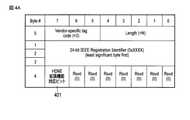
図4Aは、本実施形態に係る映像表示装置10が、映像送信装置の要求に対する応答として送出するEDIDのフォーマットの一例を示す図である。
映像表示装置10が送出するEDIDは、HDMI Forum データブロックとして、HDMI1.4bデータブロック あるいはHDMI2.xデータブロックのVendor-specific tag codeやLengthや24-bit IEEE Registration Identifierを含む。さらに映像表示装置10が送出するEDIDは、リザーブ領域の任意の領域に、HDMI拡張機能対応ビット401を含む。HDMI拡張機能対応ビット401は、Source機器である映像送信装置20に対して、HDMI拡張機能(例えばバージョン2.x互換)に準拠しているか否かを提示させるための識別ビットである。FIG. 4A is a diagram showing an example of an EDID format transmitted by the
The EDID transmitted by the
HDMI拡張機能対応ビット401を含むEDIDを受信した映像送信装置20は、HDMI拡張機能対応ビット401が”オン(例えば1)”であることを認識できる場合には、HDMI拡張機能の準拠の可否を、図4Bに示す拡張したInfoFrameを用いて映像表示装置10に対して提示する。 If the
図4Bは、本実施形態に係る映像表示装置10が受信する拡張したInfoFrameのフォーマットの一例を示す図である。
映像表示装置10が受信する拡張したInfoFrameは、Checksumや24bit IEEE Registration Identifierを含む。さらに映像表示装置10が受信する拡張したInfoFrameは、リザーブ領域の任意の領域に、HDMI拡張機能対応ビット402を含む。HDMI拡張機能対応ビット402は、図4Aに示すEDIDのHDMI拡張機能対応ビット401に対する応答として割り当てられたビットである。FIG. 4B is a diagram showing an example of an extended InfoFrame format received by the
The extended InfoFrame received by the
映像表示装置10がEDIDのHDMI拡張機能対応ビット401を“オン(例えば1)”に設定して送信する場合、映像送信装置20は、HDMI拡張機能対応ビット401の値が”オン(例えば1)”であることを認識できる場合には、HDMI拡張機能対応ビット402に値を設定して映像表示装置10に拡張したInfoFrameを送信する。映像送信装置20が拡張したInfoFrameのHDMI拡張機能対応ビット402に設定する値は、HDMI拡張機能(例えばバージョン2.x互換)に準拠している場合は、”オン(例えば1)”であり、準拠していない場合は”オフ(例えば0)”である。 When the
これにより、映像表示装置10は、映像送信装置20がHDMI拡張機能に対応しているか否かを確認することができる。以降図4Bに示すHDMI拡張機能対応ビット402を含む拡張したInfoFrameを、拡張InfoFrameと呼ぶこととする。また、HDMI拡張機能対応ビット402を含まないフォーマットのInfoFrameを、通常InfoFrameと呼ぶこととする。またInfoFrameを受信したときの映像表示装置10の処理については、図5から図10を用いて説明する。 Thereby, the
図5は、本実施形態に係る映像表示装置(Sink機器)10がHDMIケーブル30を介して接続する映像送信装置(Source機器)20の種類と、その種類に対応して映像表示装置(Sink機器)10が行う処理内容との組み合わせの一例を示す図である。 FIG. 5 shows the types of the video transmission device (Source device) 20 to which the video display device (Sink device) 10 according to the present embodiment is connected via the
No1の組み合わせは、拡張InfoFrameに対応した映像送信装置(Source機器)20と映像表示装置10(Sink機器)が行う処理との組み合わせの例である。
No2の組み合わせは、通常InfoFrameのみに対応しHDMI1.4bに準拠する映像送信装置(Source機器)20と映像表示装置(Sink機器)10が行う処理との組み合わせの例である。The combination of No. 1 is an example of a combination of a video transmission device (Source device) 20 corresponding to the extended InfoFrame and a process performed by the video display device 10 (Sink device).
The combination of No. 2 is an example of a combination of a video transmission device (Source device) 20 that normally supports only InfoFrame and conforms to HDMI 1.4b and a process performed by the video display device (Sink device) 10.
No3の組み合わせは、通常InfoFrameのみに対応しHDMI2.xに準拠する映像送信装置(Source機器)20と映像表示装置(Sink機器)10が行う処理との組み合わせの例である。
No1の組み合わせは、映像表示装置(Sink機器)10が、送信したEDIDに対応して映像送信装置20から送信された拡張InfoFrameを受信した場合に、その受信した拡張InfoFrameに含まれるHDMI拡張機能対応ビット402の値に応じてHDMI2.xで動作するか、HDMI1.4bで動作するかの制御を行うことを示している。The combination of No. 3 is an example of a combination of a video transmission device (Source device) 20 that normally supports only InfoFrame and conforms to HDMI 2.x and a process performed by the video display device (Sink device) 10.
The combination of No1 corresponds to the HDMI extended function included in the received extended InfoFrame when the video display device (Sink device) 10 receives the extended InfoFrame transmitted from the
またNo2の組み合わせは、映像表示装置(Sink機器)10が、送信したEDIDに対応して映像送信装置20から送信された通常InfoFrameを受信し場合に、継続して送られてくる映像音声信号を解析した結果に基づきHDMI1.4bでの動作に切り替え、継続して映像音声信号を受信する処理を行うことを示している。 Further, the combination of No. 2 is a continuous video / audio signal when the video display device (Sink device) 10 receives a normal InfoFrame transmitted from the
またNo3の組み合わせは、映像表示装置(Sink機器)10が、送信したEDIDに対応して映像送信装置20から送信された通常InfoFrameを受信し場合に、継続して送られてくる映像音声信号を解析した結果に基づきHDMI2.xでの動作を継続し、継続して映像信号を受信する処理を行うことを示している。 Further, the combination of No. 3 is a continuous video-audio signal when the video display device (Sink device) 10 receives the normal InfoFrame transmitted from the
図6から図9は、図5のNo1からNo3の組み合わせにおける映像表示装置(Sink機器)10と映像送信装置(Source機器)20の、電源ON以降の起動および接続に関する処理の一例を示す図である。
図6は、本実施形態に係る電子機器10が、HDMI1.4bの規格に準拠し更に図4Bに示す拡張InfoFrameをサポートする映像送信装置20と接続する場合の、接続処理シーケンスの一例を示す図である。図6に示す映像送信装置(Source機器)20はHDMI1.4bに準拠している場合であり、処理シーケンスは図5のNo1の組み合わせの場合に該当する。6 to 9 are diagrams showing an example of processing related to startup and connection of the video display device (Sink device) 10 and the video transmission device (Source device) 20 in the combination of No. 1 to No. 3 of FIG. 5 after the power is turned on. be.
FIG. 6 is a diagram showing an example of a connection processing sequence when the
映像送信装置(Source機器)20の第2通信モジュール210は、電源ON状態になると5V電源ラインに電源を供給する。映像表示装置(Sink機器)10の第1通信モジュール110は、電源ONの状態になると5V電源ラインの電圧を検出することで、映像送信装置(Source機器)20の電源が入っていることを認識する(S601)。 The
映像送信装置(Source機器)20の電源が入っていることを認識した映像表示装置(Sink機器)10の通信コントローラ152は、HPDラインを介してHPD”High ”を送信する(S602)。
映像送信装置(Source機器)20の通信コントローラ252は、HPDラインが”High ”になったことを検出することで、映像表示装置(Sink機器)10が接続したことを認識する(S602)。The
The
HPDが”High ”になったことを検出した映像送信装置(Source機器)20の通信コントローラ252は、映像表示装置(Sink機器)10の通信コントローラ152に対してEDID送信要求を送信する(S603)。
EDID送信要求を受信した映像表示装置(Sink機器)10の通信コントローラ152は、EDID送信コントローラ154によりHDMI2.xデータブロックのEDIDを映像送信装置(Source機器)20に送信する(S604)。EDID送信コントローラ154は、図4Aに示したHDMI拡張機能対応ビット401を“オン(例えば1)”に設定したEDIDを映像送信装置(Source機器)20に送信する(S604)。The
The
EDIDを受信した映像送信装置(Source機器)20は、拡張InfoFrameに対応している場合は、HDMI拡張機能対応ビット401を解析し、解析結果と自身が準拠するHDMIのバージョンとに応じて、拡張InfoFrameのHDMI拡張機能対応ビット402に設定する値を決定し、決定した値を設定して拡張InfoFrameを映像表示装置(Sink機器)10に送信する。映像送信装置(Source機器)20は、拡張InfoFrameに対応していない場合は、EDIDに含まれるHDMI拡張機能対応ビット401の存在を認識できないため、拡張InfoFrameを映像表示装置(Sink機器)10に送信しない。 When the video transmission device (Source device) 20 that has received the EDID supports the extended InfoFrame, it analyzes the HDMI extended function
図6の映像送信装置(Source機器)20は、拡張InfoFrameに対応しており、更にHDMI1.4bに準拠する映像送信装置である。したがって映像送信装置(Source機器)20は、HDMI拡張機能対応ビット402を”オフ”に設定して、TMDSエンコーダ250により拡張InfoFrameを映像表示装置(Sink機器)10に送信する(S605)。 The video transmission device (Source device) 20 of FIG. 6 is a video transmission device that supports the extended InfoFrame and further conforms to HDMI 1.4b. Therefore, the video transmission device (Source device) 20 sets the HDMI extended function
HDMI拡張機能対応ビット402が”オフ”に設定された拡張InfoFrameを受信した映像表示装置(Sink機器)10のTMDSデコーダ150は、受信した拡張InfoFrameを判定モジュール151に送信する。
判定モジュール151は、受信した拡張InfoFrameに含まれるHDMI拡張機能対応ビット402の値を解析することで、映像送信装置(Source機器)20が準拠するHDMIのバージョンを認識する。The
The
図6の場合、HDMI拡張機能対応ビット402は”オフ”( 例えばバージョン2.x互換に非対応)であるため、判定モジュール151は、映像送信装置(Source機器)20がHDMI1.4bに準拠する装置であると認識する。
以上により映像表示装置(Sink機器)10は、映像送信装置(Source機器)20がHDMI1.4bに準拠する装置であることを認識することができる。そこで映像表示装置(Sink機器)10は、HDMI1.4bとして動作するように切り替え、HDMI1.4bの動作として映像送信装置(Source機器)20と再接続を行うための処理を継続する。In the case of FIG. 6, since the HDMI extension function
From the above, the video display device (Sink device) 10 can recognize that the video transmission device (Source device) 20 is a device compliant with HDMI 1.4b. Therefore, the video display device (Sink device) 10 is switched to operate as HDMI 1.4b, and the process for reconnecting with the video transmission device (Source device) 20 is continued as the operation of HDMI 1.4b.
判定モジュール151は、映像送信装置(Source機器)20がHDMI1.4bに準拠する装置であると認識した旨を通信コントローラ152に通知する。
通知を受けた通信コントローラ152は、映像表示装置(Sink機器)10をHDMI1.4bとして動作するように切り替えて、HDMI1.4bとして映像送信装置(Source機器)20と再接続を行うために、HPDラインを介してHPD”Low ”を送信し、次にHPD”High ”を送信する(S606)。なお映像表示装置(Sink機器)10は、映像送信装置(Source機器)20とのやり取りで確定した動作(HDMI1.4bとしての動作)に関する情報を、例えばメモリ155に保存しておき、次回の映像表示装置(Sink機器)10及び映像送信機器(Source機器)20の電源ON時に送信するEDIDに用いてもよい。The
Upon receiving the notification, the
HPDが”Low ”から”High ”に遷移したことを検出した映像送信装置(Source機器)20の通信コントローラ252は、映像表示装置(Sink機器)10の通信コントローラ152に対してEDID送信要求を送信する(S607)。
EDID送信要求を受信した映像表示装置(Sink機器)10の通信コントローラ152は、EDID送信コントローラ154によりHDMI1.4bデータブロックのEDIDを映像送信装置(Source機器)20に送信する(S608)。EDID送信コントローラ154は、図4Aに示したHDMI拡張機能対応ビット401を“オフ(例えば0)”に設定したEDIDを送信する。The
The
EDIEを受信した映像送信装置(Source機器)20は、HDMI拡張機能対応ビット402を”オフ”に設定して、TMDSエンコーダ250によりInfoFrameを映像表示装置(Sink機器)10に送信する(S609)。
HDMI拡張機能対応ビット402が”オフ”に設定されたInfoFrameを受信した映像表示装置(Sink機器)10のTMDSデコーダ150は、受信したInfoFrameを判定モジュール151に送信する。The video transmission device (Source device) 20 that has received the EDIE sets the HDMI extended function
The
判定モジュール151がInfoFrameのHDMI拡張機能対応ビット402を解析することで、映像表示装置(Sink機器)10は、映像送信装置(Source機器)20がHDMI1.4bに準拠する装置であることを認識することができる。
これにより映像表示装置(Sink機器)10は、映像送信装置(Source機器)20がHDMI1.4bに準拠する装置であるものとして、映像送信装置(Source機器)20から送らてくる映像音声信号の受信処理を行うことが可能となる。When the
As a result, the video display device (Sink device) 10 receives the video / audio signal sent from the video transmission device (Source device) 20 assuming that the video transmission device (Source device) 20 is a device compliant with HDMI 1.4b. It becomes possible to perform processing.
図7は、本実施形態に係る電子機器が、HDMI2.xの規格に準拠し更に図4Bに示すInfoFrameをサポートする映像送信装置と接続する場合の、接続処理シーケンスの他の例を示す図である。図7に示す映像送信装置(Source機器)20はHDMI2.xに準拠している場合であり、処理シーケンスは図5のNo1の組み合わせの場合に該当する。 FIG. 7 is a diagram showing another example of the connection processing sequence when the electronic device according to the present embodiment is connected to a video transmission device that conforms to the HDMI 2.x standard and further supports InfoFrame shown in FIG. 4B. be. The video transmission device (Source device) 20 shown in FIG. 7 is compliant with HDMI 2.x, and the processing sequence corresponds to the case of the combination of No. 1 in FIG.
映像送信装置(Source機器)20の第2通信モジュール210は、電源ON状態になると5V電源ラインに電源を供給する。映像表示装置(Sink機器)10の第1通信モジュール110は、電源ONの状態になると5V電源ラインの電圧を検出することで、映像送信装置(Source機器)20の電源が入っていることを認識する(S701)。 The
映像送信装置(Source機器)20の電源が入っていることを認識した映像表示装置(Sink機器)10の通信コントローラ152は、HPDラインを介してHPD”High ”を送信する(S702)。
映像送信装置(Source機器)20の通信コントローラ252は、HPDラインが”High ”になったことを検出することで、映像表示装置(Sink機器)10が接続したことを認識する(S702)。The
The
HPDが”High ”になったことを検出した映像送信装置(Source機器)20の通信コントローラ252は、映像表示装置(Sink機器)10の通信コントローラ152に対してEDID送信要求を送信する(S703)。
EDID送信要求を受信した映像表示装置(Sink機器)10の通信コントローラ152は、EDID送信コントローラ154によりHDMI2.xデータブロックのEDIDを映像送信装置(Source機器)20に送信する(S704)。EDID送信コントローラ154は、図4Aに示したHDMI拡張機能対応ビット401を“オン(例えば1)”に設定したEDIDを映像送信装置(Source機器)20に送信する(S704)。The
The
EDIDを受信した映像送信装置(Source機器)20は、拡張InfoFrameに対応している場合は、HDMI拡張機能対応ビット401を解析し、解析結果と自身が準拠するHDMIのバージョンとに応じて、拡張InfoFrameのHDMI拡張機能対応ビット402に設定する値を決定し、決定した値を設定して拡張InfoFrameを映像表示装置(Sink機器)10に送信する。映像送信装置(Source機器)20は、拡張InfoFrameに対応していない場合は、EDIDに含まれるHDMI拡張機能対応ビット401の存在を認識できないため、拡張InfoFrameを映像表示装置(Sink機器)10に送信しない。 When the video transmission device (Source device) 20 that has received the EDID supports the extended InfoFrame, it analyzes the HDMI extended function
図7の映像送信装置(Source機器)20は、拡張InfoFrameに対応しており、更にHDMI2.xに準拠する映像送信装置である。したがって映像送信装置(Source機器)20は、HDMI拡張機能対応ビット402を”オン”に設定して、TMDSエンコーダ250によりInfoFrameを映像表示装置(Sink機器)10に送信する(S705)。 The video transmission device (Source device) 20 of FIG. 7 is a video transmission device that supports the extended InfoFrame and further conforms to HDMI 2.x. Therefore, the video transmission device (Source device) 20 sets the HDMI extension function
HDMI拡張機能対応ビット402が”オン”に設定された拡張InfoFrameを受信した映像表示装置(Sink機器)10のTMDSデコーダ150は、受信した拡張InfoFrameを判定モジュール151に送信する。
判定モジュール151は、受信した拡張InfoFrameに含まれるHDMI拡張機能対応ビット402の値を解析することで、映像送信装置(Source機器)20が準拠するHDMIのバージョンを認識する。The
The
図7の場合、HDMI拡張機能対応ビット402は”オン”( 例えばバージョン2.x互換に対応)であるため、判定モジュール151は、映像送信装置(Source機器)20がHDMI2.xに準拠する装置であると認識する。
以上により映像表示装置(Sink機器)10は、映像送信装置(Source機器)20がHDMI2.xに準拠する装置であることを認識することができる。映像表示装置(Sink機器)10は、HDMI2.xとして動作するように設定されているため、映像表示装置(Sink機器)10の判定モジュール151は、映像送信装置(Source機器)20との接続処理を終了する。なお映像表示装置(Sink機器)10は、映像送信装置(Source機器)20とのやり取りで確定した動作(HDMI2.xとしての動作)に関する情報を、例えばメモリ155に保存しておき、次回の映像表示装置(Sink機器)10及び映像送信機器(Source機器)20の電源ON時に送信するEDIDに用いてもよい。In the case of FIG. 7, since the HDMI extension function
From the above, the video display device (Sink device) 10 can recognize that the video transmission device (Source device) 20 is a device compliant with HDMI 2.x. Since the video display device (Sink device) 10 is set to operate as HDMI 2.x, the
これにより映像表示装置(Sink機器)10は、映像送信装置(Source機器)20がHDMI2.xに準拠する装置であるものとして、映像送信装置(Source機器)20から送らてくる映像音声信号の受信処理を行うことが可能となる。
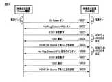
図8は、本実施形態に係る電子機器10が、HDMI1.4bの規格に準拠し図4Bに示す拡張InfoFrameをサポートしない映像送信装置と接続する場合の、接続処理シーケンスの他の例を示す図である。図8に示す映像送信装置(Source機器)20はHDMI1.4bに準拠している場合であり、処理シーケンスは図5のNo2の組み合わせの場合に該当する。As a result, the video display device (Sink device) 10 receives the video / audio signal sent from the video transmission device (Source device) 20, assuming that the video transmission device (Source device) 20 is a device compliant with HDMI 2.x. It becomes possible to perform processing.
FIG. 8 is a diagram showing another example of the connection processing sequence when the
映像送信装置(Source機器)20の第2通信モジュール210は、電源ON状態になると5V電源ラインに電源を供給する。映像表示装置(Sink機器)10の第1通信モジュール110は、電源ONの状態になると5V電源ラインの電圧を検出することで、映像送信装置(Source機器)20の電源が入っていることを認識する(S801)。 The
映像送信装置(Source機器)20の電源が入っていることを認識した映像表示装置(Sink機器)10の通信コントローラ152は、HPDラインを介してHPD”High ”を送信する(S802)。
映像送信装置(Source機器)20の通信コントローラ252は、HPDラインが”High ”になったことを検出することで、映像表示装置(Sink機器)10が接続したことを認識する(S802)。The
The
HPDが”High ”になったことを検出した映像送信装置(Source機器)20の通信コントローラ252は、映像表示装置(Sink機器)10の通信コントローラ152に対してEDID送信要求を送信する(S803)。
EDID送信要求を受信した映像表示装置(Sink機器)10の通信コントローラ152は、EDID送信コントローラ154によりHDMI2.xデータブロックのEDIDを映像送信装置(Source機器)20に送信する(S804)。EDID送信コントローラ154は、図4Aに示したHDMI拡張機能対応ビット401を“オン(例えば1)”に設定したEDIDを送信する。The
The
EDIDを受信した映像送信装置(Source機器)20は、拡張InfoFrameに対応している場合は、HDMI拡張機能対応ビット401を解析し、解析結果と自身が準拠するHDMIのバージョンとに応じて、拡張InfoFrameのHDMI拡張機能対応ビット402に設定する値を決定し、決定した値を設定して拡張InfoFrameを映像表示装置(Sink機器)10に送信する。映像送信装置(Source機器)20は、拡張InfoFrameに対応していない場合は、EDIDに含まれるHDMI拡張機能対応ビット401の存在を認識できないため、拡張InfoFrameを映像表示装置(Sink機器)10に送信しない。 When the video transmission device (Source device) 20 that has received the EDID supports the extended InfoFrame, it analyzes the HDMI extended function
図8の映像送信装置(Source機器)20は、拡張InfoFrameに対応しておらず、更にHDMI1.4に準拠する映像送信装置である。したがって映像送信装置(Source機器)20は、受信したEDIDのHDMI拡張機能対応ビット401を認識できず、拡張InfoFrameを送信せずに、TMDSエンコーダ250によりHDMI1.4bに準拠した映像音声信号の送信を行う(S805)。 The video transmission device (Source device) 20 of FIG. 8 is a video transmission device that does not support the extended InfoFrame and further conforms to HDMI 1.4. Therefore, the video transmission device (Source device) 20 cannot recognize the received EDID HDMI extended function
HDMI1.4bに準拠した映像音声信号を受信した映像表示装置(Sink機器)10のTMDSデコーダ150は、受信した映像音声信号を解析することで、受信した映像音声信号がHDMI1.4bに準拠する信号であること認識するとともに、拡張InfoFrameを受信していないことを認識する。 The
TMDSデコーダ150は、受信した映像音声信号がHDMI1.4bに準拠する信号であることを認識するのに、例えば
(1)HDMI信号レートが10.2Gbps以下で、色空間が4:2:0フォーマットでない、あるいはHDRフォーマットでない
(2)DVI信号が含まれる
のいずれかに該当する場合、TMDSデコーダ150は、受信した映像音声信号がHDMI1.4bに準拠する信号である、と認識する。TMDSデコーダ150は、これらの情報以外にも、HDMI1.4bの属性を示す情報を用いて、受信した映像音声信号がHDMI1.4bに準拠する信号であることを認識してもよい。The
(1) The HDMI signal rate is 10.2 Gbps or less, and the color space is not in 4: 2: 0 format or HDR format.
(2) If any of the DVI signals are included, the
以上により映像表示装置(Sink機器)10は、映像送信装置(Source機器)20がHDMI1.4bに準拠する装置であることを認識することができる。そこで映像表示装置(Sink機器)10は、HDMI1.4bとして動作するように切り替え、HDMI1.4bの動作として映像送信装置(Source機器)20と再接続を行うための処理を継続する。 From the above, the video display device (Sink device) 10 can recognize that the video transmission device (Source device) 20 is a device compliant with HDMI 1.4b. Therefore, the video display device (Sink device) 10 is switched to operate as HDMI 1.4b, and the process for reconnecting with the video transmission device (Source device) 20 is continued as the operation of HDMI 1.4b.
TMDSデコーダ150は、映像送信装置(Source機器)20がHDMI1.4bに準拠する装置であると認識した旨を通信コントローラ152に通知する。
通知を受けた通信コントローラ152は、映像表示装置(Sink機器)10をHDMI1.4bとして動作するように切り替えて、HDMI1.4bとして映像送信装置(Source機器)20と再接続を行うために、HPDラインを介してHPD”Low ”を送信し、次にHPD”High ”を送信する(S806)。なお映像表示装置(Sink機器)10は、映像送信装置(Source機器)20とのやり取りで確定した動作(HDMI1.4bとしての動作)に関する情報を、例えばメモリ155に保存しておき、次回の映像表示装置(Sink機器)10及び映像送信機器(Source機器)20の電源ON時に送信するEDIDに用いてもよい。The
Upon receiving the notification, the
HPDが”Low ”から”High ”になったことを検出した映像送信装置(Source機器)20の通信コントローラ252は、映像表示装置(Sink機器)10の通信コントローラ152に対してEDID送信要求を送信する(S807)。
EDID送信要求を受信した映像表示装置(Sink機器)10の通信コントローラ152は、EDID送信コントローラ154によりHDMI1.4bデータブロックのEDIDを映像送信装置(Source機器)20に送信する(S808)。EDID送信コントローラ154は、図4Aに示したHDMI拡張機能対応ビット401を“オフ(例えば0)”に設定したEDIDを送信する。The
The
EDIEを受信した映像送信装置(Source機器)20は、以降HDMI1.4bに準拠した映像音声信号を送信する(809)。
これにより映像表示装置(Sink機器)10は、映像送信装置(Source機器)20がHDMI1.4bに準拠する装置であるものとして、映像送信装置(Source機器)20から送らてくる映像音声信号の受信処理を行うことが可能となる。The video transmission device (Source device) 20 that has received the EDIE subsequently transmits a video / audio signal conforming to HDMI 1.4b (809).
As a result, the video display device (Sink device) 10 receives the video / audio signal sent from the video transmission device (Source device) 20 assuming that the video transmission device (Source device) 20 is a device compliant with HDMI 1.4b. It becomes possible to perform processing.
なおTMDSデコーダ150は、S805において受信した映像音声信号がHDMI1.4bに準拠する信号であること認識した以降に、拡張InfoFrameを受信する場合も想定される。この場合映像表示装置(Sink機器)10は、既に設定されているHDMI1.4bに準拠した動作を継続してもよいし、受信した拡張InfoFrameに応じて、準拠して動作するHDMIのバージョンを決定してもよい。 It is also assumed that the
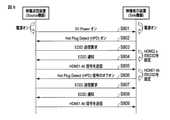
図9は、本実施形態に係る電子機器が、HDMI2.xの規格に準拠し更に図5に示すInfoFrameをサポートしない映像送信装置と接続する場合の、接続処理シーケンスの他の例を示す図である。図9に示す映像送信装置(Source機器)20はHDMI2.xに準拠している場合であり、処理シーケンスは図5のNo3の組み合わせの場合に該当する。 FIG. 9 is a diagram showing another example of the connection processing sequence when the electronic device according to the present embodiment is connected to a video transmission device that conforms to the HDMI 2.x standard and does not support the InfoFrame shown in FIG. be. The video transmission device (Source device) 20 shown in FIG. 9 is compliant with HDMI 2.x, and the processing sequence corresponds to the case of the combination of No. 3 in FIG.
映像送信装置(Source機器)20の第2通信モジュール210は、電源ON状態になると5V電源ラインに電源を供給する。映像表示装置(Sink機器)10の第1通信モジュール110は、電源ONの状態になると5V電源ラインの電圧を検出することで、映像送信装置(Source機器)20の電源が入っていることを認識する(S901)。 The
映像送信装置(Source機器)20の電源が入っていることを認識した映像表示装置(Sink機器)10の通信コントローラ152は、HPDラインを介してHPD”High ”を送信する(S902)。
映像送信装置(Source機器)20の通信コントローラ252は、HPDラインが”High ”になったことを検出することで、映像表示装置(Sink機器)10が接続したことを認識する(S902)。The
The
HPDが”High ”になったことを検出した映像送信装置(Source機器)20の通信コントローラ252は、映像表示装置(Sink機器)10の通信コントローラ152に対してEDID送信要求を送信する(S903)。
EDID送信要求を受信した映像表示装置(Sink機器)10の通信コントローラ152は、EDID送信コントローラ154によりHDMI2.xデータブロックのEDIDを映像送信装置(Source機器)20に送信する(S904)。EDID送信コントローラ154は、図4Aに示したHDMI拡張機能対応ビット401を“オン(例えば1)”に設定したEDIDを映像送信装置(Source機器)20に送信する。The
The
EDIDを受信した映像送信装置(Source機器)20は、拡張InfoFrameに対応している場合は、HDMI拡張機能対応ビット401を解析し、解析結果と自身が準拠するHDMIのバージョンとに応じて、拡張InfoFrameのHDMI拡張機能対応ビット402の値を決定し、決定した値を設定して拡張InfoFrameを映像表示装置(Sink機器)10に送信する。映像送信装置(Source機器)20は、拡張InfoFrameに対応していない場合は、EDIDに含まれるHDMI拡張機能対応ビット401の存在を認識できないため、拡張InfoFrameを映像表示装置(Sink機器)10に送信しない。 When the video transmission device (Source device) 20 that has received the EDID supports the extended InfoFrame, it analyzes the HDMI extended function
図9の映像送信装置(Source機器)20は、拡張InfoFrameに対応しておらず、更にHDMI2.xに準拠する映像送信装置である。したがって映像送信装置(Source機器)20は、拡張InfoFrameを送信せずに、TMDSエンコーダ250によりHDMI2.xに準拠した映像音声信号の送信を行う(S905)。 The video transmission device (Source device) 20 of FIG. 9 is a video transmission device that does not support the extended InfoFrame and further conforms to HDMI 2.x. Therefore, the video transmission device (Source device) 20 transmits a video / audio signal conforming to HDMI 2.x by the
HDMI2.xに準拠した映像音声信号を受信した映像表示装置(Sink機器)10のTMDSデコーダ150は、受信した映像音声信号を解析することで、受信した映像音声信号がHDMI1.4bに準拠する信号であること認識するとともに、拡張InfoFrameを受信していないことを認識する。 The
以上により映像表示装置(Sink機器)10は、映像送信装置(Source機器)20がHDMI2.xに準拠する装置であることを認識することができる。映像表示装置(Sink機器)10は、HDMI2.xとして動作するように設定されているため、映像表示装置(Sink機器)10のTMDSデコーダ150は、映像送信装置(Source機器)20との接続処理を終了する。なお映像表示装置(Sink機器)10は、映像送信装置(Source機器)20とのやり取りで確定した動作(HDMI2.xとしての動作)に関する情報を、例えばメモリ155に保存しておき、次回の映像表示装置(Sink機器)10及び映像送信機器(Source機器)20の電源ON時に送信するEDIDに用いてもよい。 From the above, the video display device (Sink device) 10 can recognize that the video transmission device (Source device) 20 is a device compliant with HDMI 2.x. Since the video display device (Sink device) 10 is set to operate as HDMI 2.x, the
これにより映像表示装置(Sink機器)10は、映像送信装置(Source機器)20がHDMI2.xに準拠する装置であるものとして、映像送信装置(Source機器)20から送らてくる映像音声信号の受信処理を行うことが可能となる。
図10は、本実施形態に係る電子機器が、接続する映像送信装置が準拠するHDMIのバージョンに応じて、動作するHDMIのバージョンを切り替える処理フローの一例を示す図である。As a result, the video display device (Sink device) 10 receives the video / audio signal sent from the video transmission device (Source device) 20, assuming that the video transmission device (Source device) 20 is a device compliant with HDMI 2.x. It becomes possible to perform processing.
FIG. 10 is a diagram showing an example of a processing flow in which an electronic device according to the present embodiment switches an operating HDMI version according to the HDMI version to which the connected video transmission device complies.
映像表示装置(Sink機器)10は、映像送信装置(Source機器)20との接続を開始すると、動作するHDMIのバージョンを切り替える処理を開始する(S1000)。映像送信装置(Source機器)20との接続の開始とは、例えば図6のS601の映像表示装置(Sink機器)10が5V電源ラインの電圧を検出したタイミングである。 When the video display device (Sink device) 10 starts connecting to the video transmission device (Source device) 20, it starts a process of switching the version of HDMI that operates (S1000). The start of connection with the video transmission device (Source device) 20 is, for example, the timing when the video display device (Sink device) 10 of S601 in FIG. 6 detects the voltage of the 5V power supply line.
映像表示装置(Sink機器)10は、HDMI2.xとして動作するように種々の機能を設定する(S1001)。
映像表示装置(Sink機器)10は、映像送信装置(Source機器)20から拡張InfoFrameを受信すると(S1002、S1003)、HDMI拡張機能対応ビット402の値を解析する。The video display device (Sink device) 10 sets various functions so as to operate as HDMI 2.x (S1001).
When the video display device (Sink device) 10 receives the extended InfoFrame from the video transmitting device (Source device) 20 (S1002, S1003), the video display device (Sink device) 10 analyzes the value of the HDMI extended function
解析の結果HDMI拡張機能対応ビット402が“オン”の場合(S1002のYes)、映像表示装置(Sink機器)10は、HDMI2.xとしての動作を継続する。映像表示装置(Sink機器)10が、HDMI2.xとしての動作を継続する処理は、例えば図7のS705の拡張InfoFrameを受信した以降の処理である。 As a result of the analysis, when the HDMI expansion function
解析の結果HDMI拡張機能対応ビット402が“オフ”の場合(S1003のYes)、映像表示装置(Sink機器)10は、HDMI1.4bとしての動作に切り替えを行う。映像表示装置(Sink機器)10が、HDMI1.4bとしての動作に切り替える処理は、例えば図6のS606の映像送信装置(Source機器)20との再接続以降の処理である。 As a result of the analysis, when the HDMI expansion function
映像表示装置(Sink機器)10は、映像送信装置(Source機器)20から拡張InfoFrameを受信せずに、HDMIの映像音声信号を受信すると(S1005、S1006)、受信した映像音声信号が準拠するHDMIのバージョンを解析する。 When the video display device (Sink device) 10 receives the HDMI video / audio signal from the video transmission device (Source device) 20 without receiving the extended InfoFrame (S1005, S1006), the received video / audio signal conforms to the HDMI. Analyze the version of.
解析の結果HDMIのバージョンがHDMI2.xの場合(S1005のYes)、映像表示装置(Sink機器)10は、HDMI2.xとしての動作を継続する。映像表示装置(Sink機器)10が、HDMI2.xとしての動作を継続する処理は、例えば図9のS905のHDMI2.xに準拠した映像音声信号を受信した以降の処理である。 As a result of the analysis, when the HDMI version is HDMI 2.x (Yes of S1005), the video display device (Sink device) 10 continues to operate as HDMI 2.x. The process in which the video display device (Sink device) 10 continues to operate as HDMI 2.x is, for example, the process after receiving the video / audio signal compliant with HDMI 2.x in S905 of FIG.
解析の結果HDMIのバージョンがHDMI1.4bの場合(S1006のYes)、映像表示装置(Sink機器)10は、HDMI1.4bのとしての動作に切り替えを行う。映像表示装置(Sink機器)10が、HDMI1.4bとしての動作に切り替える処理は、例えば図8のS805のHDMI1.4bに準拠した映像音声信号を受信した以降の処理である。 As a result of the analysis, when the HDMI version is HDMI 1.4b (Yes of S1006), the video display device (Sink device) 10 switches to the operation as HDMI 1.4b. The process of switching the operation of the video display device (Sink device) 10 to the operation as HDMI 1.4b is, for example, the process after receiving the video / audio signal compliant with HDMI 1.4b of S805 of FIG.
映像表示装置(Sink機器)10は、動作するHDMIのバージョンを確定させると、切り替え処理を終了する(S1020)。
図10の動作するHDMIのバージョンを切り替える処理フローは、映像表示装置(Sink機器)10が、5V電源ラインの電圧を検出することで、新たな映像送信装置(Source機器)との接続を認識するごとに行われる。When the video display device (Sink device) 10 determines the version of HDMI to operate, the switching process ends (S1020).
In the processing flow for switching the operating HDMI version in FIG. 10, the video display device (Sink device) 10 recognizes the connection with the new video transmission device (Source device) by detecting the voltage of the 5V power supply line. It is done every time.
上記説明では、HDMIのバージョンとして上位のバージョンをHDMI2.x、下位のバージョンをHDMI1.4bとして説明したが、これに限らず、上位のバージョンをHDMI2.x、下位のバージョンをHDMI1.xとしてもよい。
また上記説明では、図4Aに示すEDIDのHDMI拡張機能対応ビット401に対応して、映像送信装置20が拡張InfoFrameを送信する場合を例に説明したが、それに限らない。In the above explanation, the upper version is HDMI2.x and the lower version is HDMI1.4b as the HDMI version, but it is not limited to this, and the upper version can be HDMI2.x and the lower version can be HDMI1.x. good.
Further, in the above description, the case where the
例えば図4Aに示すEDIDのHDMI拡張機能対応ビット401に対応して、映像送信装置20の通信コントローラ252がCECラインやDDCラインの信号により、HDMI拡張機能対応ビット402に対応する制御情報を映像表示装置10に送信してもよい。 For example, corresponding to the HDMI expansion function
この場合映像表示装置10及び映像送信装置20の処理は、例えば図6の拡張InfoFrameを映像表示装置(Sink機器)10に送信する処理(S605)においては、CECラインやDDCラインの信号によりHDMI拡張機能対応ビット402に対応する制御情報を送信する処理に置き換えればよい。 In this case, the processing of the
さらにまた上記説明では、拡張InfoFrameのフォーマットは、図4Bに示すようにHDMI拡張機能対応ビット402を含む場合を例に説明したが、それに限らない。拡張InfoFrameのフォーマット例は、HDMI拡張機能対応ビット402の代わりに、HDMI拡張機能対応ビット401に対応して、対応する機能を含むフォーマットとしてもよい。具体的には拡張InfoFrameのフォーマット例は、HDMI2.xの特定機能を示す制御情報を、応答情報として含んでもよい。あるいは拡張InfoFrameのフォーマット例は、HDMI拡張機能対応ビット402と、HDMI拡張機能対応ビット401に対応して、対応する特定機能を示す制御情報と両方を応答情報として含んでもよい。 Furthermore, in the above description, the format of the extended InfoFrame has been described by taking the case of including the HDMI extended function
この場合映像表示装置10及び映像送信装置20の処理は、例えば図6の拡張InfoFrameを受信(S605)した映像表示装置(Sink機器)10の判定モジュール151の処理においては、応答情報を解析する処理に置き換えればよい。
さらにまた上記説明では、映像表示装置10と映像送信装置20とが再接続するための処理として、HPDラインを用いた処理を例に説明したが、それに限らない。映像表示装置10と映像送信装置20とが再接続の時間を短縮するために、映像表示装置10の通信コントローラ152がCECラインやDDCラインの信号により、自身が設定するEDIDの内容が変わった旨(EDIE変更通知)を通知し、この通知を受けた映像送信装置20がEDID送信要求を送信してもよい。In this case, the processing of the
Furthermore, in the above description, as a process for reconnecting the
この場合映像表示装置10及び映像送信装置20の処理は、例えば図6のHot Plug Detect(HDP)オンの処理の代わりに、映像表示装置10が映像送信装置20に対してEDID変更通知を送信する処理に置き換えればよい。
以上のように、本発明の実施形態に係る映像表示装置(Sink機器)10は、種々のHDMIのバージョンの映像送信装置(Source機器)20と接続する際に、映像送信装置(Source機器)20から送られてくる拡張InfoFrameに含まれるHDMI拡張機能対応ビットの値に従って、動作するHDMIのバージョンを決定することができる。さらに映像表示装置(Sink機器)10は、映像送信装置(Source機器)20から拡張InfoFrameが送られてこない場合は、映像送信装置(Source機器)20から送られてくる映像音声信号を解析し、その解析結果に応じて、動作するHDMIのバージョンを決定することができる。In this case, in the processing of the
As described above, when the video display device (Sink device) 10 according to the embodiment of the present invention is connected to the video transmission device (Source device) 20 of various HDMI versions, the video transmission device (Source device) 20 The HDMI extension version that works can be determined according to the value of the HDMI extension support bit included in the extension InfoFrame sent from. Further, the video display device (Sink device) 10 analyzes the video / audio signal sent from the video transmission device (Source device) 20 when the extended InfoFrame is not sent from the video transmission device (Source device) 20. Depending on the analysis result, the working HDMI version can be determined.
このように動作することで、映像表示装置(Sink機器)10は、互いに異なるHDMIバージョンの映像送信装置(Source機器)20と接続する場合でも、また映像送信装置(Source機器)20が拡張InfoFrameの対応の有無に関わらず、受信した映像音声信号を正常にディスプレイ13に表示したりスピーカー15に出力したりすることが可能となる。 By operating in this way, even when the video display device (Sink device) 10 is connected to a video transmission device (Source device) 20 having different HDMI versions, the video transmission device (Source device) 20 is an extended InfoFrame. Regardless of whether or not there is a correspondence, the received video / audio signal can be normally displayed on the
また映像表示装置(Sink機器)10は、拡張InfoFrameに対応した映像送信装置(Source機器)20と接続する場合、受信した映像音声信号ではなく受信した拡張InfoFrameのHDMI拡張機能対応ビット402の値に応じて、映像送信装置(Source機器)20が動作するHDMIのバージョンを決定するため、映像音声信号により映像送信装置(Source機器)20が動作するHDMIのバージョンを決定する場合に比べて、動作するHDMIのバージョンを正確に決定することができる。これは例えば、HDMI2.xに準拠する映像送信装置(Source機器)20が、ユーザ操作によりHDMI1.4bに準拠する映像音声信号を送信する場合が想定されるからである。 Further, when the video display device (Sink device) 10 is connected to the video transmission device (Source device) 20 compatible with the extended InfoFrame, the value of the HDMI extended function
本発明のいくつかの実施形態を説明したが、これらの実施形態は例として提示したものであり、発明の範囲を限定することは意図していない。これら新規な実施形態は、その他の様々な形態で実施されることが可能であり、発明の要旨を逸脱しない範囲で、種々の省略、置き換え、変更を行うことができる。これら実施形態やその変形は、発明の範囲や要旨に含まれるとともに、特許請求の範囲に記載された発明とその均等の範囲に含まれる。さらにまた、請求項の各構成要素において、構成要素を分割して表現した場合、或いは複数を合わせて表現した場合、或いはこれらを組み合わせて表現した場合であっても本発明の範疇である。また請求項を制御ロジックとして表現した場合、コンピュータを実行させるインストラクションを含むプログラムとして表現した場合、及び前記インストラクションを記載したコンピュータ読み取り可能な記録媒体として表現した場合でも本発明の装置を適用したものである。また、使用している名称や用語についても限定されるものではなく、他の表現であっても実質的に同一内容、同趣旨であれば、本発明に含まれるものである。 Although some embodiments of the present invention have been described, these embodiments are presented as examples and are not intended to limit the scope of the invention. These novel embodiments can be implemented in various other embodiments, and various omissions, replacements, and changes can be made without departing from the gist of the invention. These embodiments and variations thereof are included in the scope and gist of the invention, and are also included in the scope of the invention described in the claims and the equivalent scope thereof. Furthermore, in each of the constituent elements of the claim, even if the constituent elements are divided and expressed, or a plurality of the constituent elements are expressed together, or even if they are expressed in combination, it is within the scope of the present invention. Further, the apparatus of the present invention is applied even when the claim is expressed as a control logic, when it is expressed as a program including an instruction for executing a computer, and when it is expressed as a computer-readable recording medium in which the instruction is described. be. Further, the names and terms used are not limited, and other expressions are included in the present invention as long as they have substantially the same content and the same meaning.
10・・・映像表示装置、20・・・映像送信装置、110・・・第1通信モジュール、210・・・第2通信モジュール、151・・・判定モジュール、152・・・通信コントローラ、153・・・EDID処理モジュール。10 ... Video display device, 20 ... Video transmission device, 110 ... First communication module, 210 ... Second communication module, 151 ... Judgment module, 152 ... Communication controller, 153.・ ・ EDID processing module.
Claims (1)
Translated fromJapanese前記他の電子機器に対して、HDMI2.xの対応の有無を示す識別ビットを含む第1のEDIDを保持するメモリと、
前記メモリに保存されている前記第1のEDIDを送信する送信部と、
前記他の電子機器から送られてくる信号を受信する受信部と、
を具備し、
前記他の電子機器から、前記識別ビットに応答して設定された第1の応答情報を含む第1の制御情報を前記受信部で受信した場合は、HDMIのバージョンとして前記HDMI2.xを決定し、
前記他の電子機器から、前記識別ビットに応答して設定された第2の応答情報を含む第2の制御情報を前記受信部で受信した場合は、前記HDMIのバージョンとしてHDMI1.xを決定し、
前記他の電子機器から、映像音声信号を前記受信部で受信した場合は、前記映像音声信号を解析することによって、HDMI信号レートが10.2Gbps以下で、色空間が4:2:0でない、あるいはHDRフォーマットでないという第1の条件及びDVI信号が含まれるという第2の条件を満たさない場合に、前記HDMIのバージョンとして前記HDMI2.xを決定する電子機器。In electronic devices that connect to other electronic devices in compliance with the HDMI standard
A memory that holds a first EDID that includes an identification bit thatindicates whether HDMI 2.x is supported for the other electronic devices.
A transmission unit that transmits the first EDID stored in the memory, and
A receiver that receives signals sent from the other electronic devices, and
Equipped with
When the receiving unit receives the first control information including thefirst response information set in response to the identification bit from the other electronic device, the HDMI2.x is determinedas the HDMI version . death,
When the receiving unit receives the second control information including the second response information set in response to the identification bit from the other electronic device, HDMI 1.x is determined as the HDMI version. ,
Whenthe video / audio signal is received by the receiver from the other electronic device, the HDMI signal rate is 10.2 Gbps or less and the color space is not 4: 2: 0 by analyzing the video / audio signal. Alternatively, an electronic device that determines HDMI 2.x as the HDMI version when the first condition that it is not in HDR format and the second condition that it contains a DVI signal are not satisfied .
Priority Applications (3)
| Application Number | Priority Date | Filing Date | Title |
|---|---|---|---|
| JP2019047270AJP7003079B2 (en) | 2019-03-14 | 2019-03-14 | Electronics |
| US16/556,448US10631041B1 (en) | 2019-03-14 | 2019-08-30 | Electronic device |
| US16/809,631US11184667B2 (en) | 2019-03-14 | 2020-03-05 | Electronic device |
Applications Claiming Priority (1)
| Application Number | Priority Date | Filing Date | Title |
|---|---|---|---|
| JP2019047270AJP7003079B2 (en) | 2019-03-14 | 2019-03-14 | Electronics |
Publications (2)
| Publication Number | Publication Date |
|---|---|
| JP2020150445A JP2020150445A (en) | 2020-09-17 |
| JP7003079B2true JP7003079B2 (en) | 2022-01-20 |
Family
ID=70285155
Family Applications (1)
| Application Number | Title | Priority Date | Filing Date |
|---|---|---|---|
| JP2019047270AActiveJP7003079B2 (en) | 2019-03-14 | 2019-03-14 | Electronics |
Country Status (2)
| Country | Link |
|---|---|
| US (2) | US10631041B1 (en) |
| JP (1) | JP7003079B2 (en) |
Families Citing this family (7)
| Publication number | Priority date | Publication date | Assignee | Title |
|---|---|---|---|---|
| JP7003079B2 (en)* | 2019-03-14 | 2022-01-20 | 株式会社東芝 | Electronics |
| CN118921520A (en)* | 2019-12-17 | 2024-11-08 | 索尼集团公司 | Receiving apparatus, method for controlling receiving apparatus, and transmitting/receiving system |
| CN111343479A (en)* | 2020-03-04 | 2020-06-26 | 深圳市朗强科技有限公司 | Method and equipment for sending and receiving audio and video data in long-distance transmission scene |
| KR20220000747A (en)* | 2020-06-26 | 2022-01-04 | 삼성전자주식회사 | Sink apparatus, souece apparatus and control methods thereof |
| US11477517B2 (en)* | 2020-11-18 | 2022-10-18 | Lg Electronics Inc. | Display device and EDID information changing method thereof |
| CN119278630A (en) | 2022-08-26 | 2025-01-07 | 三星电子株式会社 | Information sink device, information source device and method thereof |
| KR20240029322A (en)* | 2022-08-26 | 2024-03-05 | 삼성전자주식회사 | Sink device, source device and method thereof |
Citations (3)
| Publication number | Priority date | Publication date | Assignee | Title |
|---|---|---|---|---|
| JP2011030179A (en) | 2009-06-29 | 2011-02-10 | Sony Corp | Image data transmission device, control method and program |
| JP2016163238A (en) | 2015-03-04 | 2016-09-05 | シャープ株式会社 | Display device and information rewriting method |
| US20170195722A1 (en) | 2016-01-06 | 2017-07-06 | Samsung Electronics Co., Ltd. | Video content providing apparatus, control method thereof and system |
Family Cites Families (49)
| Publication number | Priority date | Publication date | Assignee | Title |
|---|---|---|---|---|
| JP4192371B2 (en)* | 1999-12-09 | 2008-12-10 | ソニー株式会社 | Data receiving apparatus, data transmitting apparatus, and data transmitting / receiving system |
| KR20060100191A (en)* | 2005-03-16 | 2006-09-20 | 삼성전자주식회사 | Output control method of HDM device and HDM device |
| JP5218845B2 (en)* | 2006-11-07 | 2013-06-26 | ソニー株式会社 | COMMUNICATION SYSTEM, TRANSMISSION DEVICE, RECEPTION DEVICE, COMMUNICATION METHOD, PROGRAM, AND COMMUNICATION CABLE |
| WO2008056709A1 (en)* | 2006-11-07 | 2008-05-15 | Sony Corporation | Receiver, delayed information transmitting method for receivers, audio output device, and delay control method for audio output devices |
| JP4343967B2 (en)* | 2007-02-28 | 2009-10-14 | キヤノン株式会社 | Communication device and control method thereof |
| JP5240492B2 (en)* | 2007-06-26 | 2013-07-17 | ソニー株式会社 | Communication system and communication method |
| JP5003389B2 (en)* | 2007-09-28 | 2012-08-15 | ソニー株式会社 | Electronic device and control method in electronic device |
| JP4835568B2 (en)* | 2007-09-28 | 2011-12-14 | ソニー株式会社 | Display device, data transmission method in display device, transmission device, and data reception method in transmission device |
| JP4766026B2 (en)* | 2007-10-05 | 2011-09-07 | ソニー株式会社 | Electronic device and method for canceling firewall of electronic device |
| JP4479776B2 (en)* | 2007-10-05 | 2010-06-09 | ソニー株式会社 | Display device and transmission device |
| JP4743196B2 (en)* | 2007-12-14 | 2011-08-10 | ソニー株式会社 | Electronic device and loop determination method in electronic device |
| KR101623890B1 (en)* | 2007-12-20 | 2016-06-07 | 에이티아이 테크놀로지스 유엘씨 | Adjusting video processing in a system haivng a video source device and a video sink device |
| JP4309451B2 (en)* | 2007-12-21 | 2009-08-05 | 株式会社東芝 | Information processing device |
| JP5593596B2 (en)* | 2008-02-04 | 2014-09-24 | ソニー株式会社 | Video signal transmitting apparatus and video signal transmitting method |
| JP2009194484A (en)* | 2008-02-12 | 2009-08-27 | Toshiba Corp | Data transmission device |
| CN101605233A (en)* | 2008-06-10 | 2009-12-16 | 株式会社东芝 | Communication device for providing communication between electronic devices |
| JP2010088092A (en)* | 2008-09-02 | 2010-04-15 | Panasonic Corp | Three-dimensional video transmission system, video display device and video output device |
| US9055278B2 (en)* | 2009-01-07 | 2015-06-09 | Dolby Laboratories Licensing Corporation | Conversion, correction, and other operations related to multiplexed data sets |
| JP2010193247A (en)* | 2009-02-19 | 2010-09-02 | Sanyo Electric Co Ltd | Hdmi apparatus |
| JP5391911B2 (en)* | 2009-08-05 | 2014-01-15 | ソニー株式会社 | Electronics |
| JP5577789B2 (en)* | 2010-03-25 | 2014-08-27 | ソニー株式会社 | Image data transmitting apparatus, image data transmitting method, and image data receiving apparatus |
| CN102893599B (en)* | 2010-05-19 | 2013-11-06 | 夏普株式会社 | Playback device, display device, television receiver, system, identification method, program, and recording medium |
| JP2012010311A (en)* | 2010-05-26 | 2012-01-12 | Sony Corp | Transmitter, transmission method, receiver, reception method and transmission/reception system |
| JP5444310B2 (en)* | 2011-11-17 | 2014-03-19 | 株式会社東芝 | Bidirectional communication interface device, transmission device, and reception device |
| WO2013129785A1 (en)* | 2012-02-29 | 2013-09-06 | Samsung Electronics Co., Ltd. | Data transmitter, data receiver, data transceiving system, data transmitting method, data receiving method, and data transceiving method |
| JP2013243473A (en)* | 2012-05-18 | 2013-12-05 | Canon Inc | Transmitter, control method and program |
| JP5390667B2 (en)* | 2012-06-11 | 2014-01-15 | 株式会社東芝 | Video transmission device and video reception device |
| JP2014063259A (en)* | 2012-09-20 | 2014-04-10 | Fujitsu Ltd | Terminal apparatus and processing program |
| US9848218B2 (en)* | 2013-01-28 | 2017-12-19 | Samsung Electronics Co., Ltd. | Source device, content providing method using the source device, sink device and controlling method of the sink device |
| GB201301489D0 (en)* | 2013-01-28 | 2013-03-13 | Adder Tech Ltd | Digital video and data transmission |
| WO2014121283A2 (en)* | 2013-02-04 | 2014-08-07 | Spectra7 Microsystems Ltd | Methods and systems for achieving higher video throughput and/or quality |
| EP2814251A1 (en)* | 2013-06-14 | 2014-12-17 | Pace Plc | Method and system for operating a set-top-box supporting 3D video content |
| US9009361B2 (en)* | 2013-06-25 | 2015-04-14 | Kabushiki Kaisha Toshiba | Video processing system, video output apparatus, video display apparatus and video processing method |
| JP2015106825A (en)* | 2013-11-29 | 2015-06-08 | 株式会社東芝 | Signal transmission method and electronic apparatus |
| EP3125566A4 (en)* | 2014-03-24 | 2017-12-13 | Lg Electronics Inc. | Device and method for data transmission and reception using hdmi |
| WO2015190877A1 (en)* | 2014-06-12 | 2015-12-17 | 엘지전자(주) | Method and device for transmitting/receiving data using hdmi |
| US9300895B2 (en)* | 2014-08-05 | 2016-03-29 | Echostar Uk Holdings Limited | Systems, methods, and apparatus for facilitating expansion of media device interface capabilities |
| WO2016021809A1 (en)* | 2014-08-08 | 2016-02-11 | 엘지전자 주식회사 | Video data processing method and device for reproducing display-adaptive image |
| US9305516B1 (en)* | 2014-09-19 | 2016-04-05 | Kabushiki Kaisha Toshiba | Electronic device |
| JP2016122873A (en)* | 2014-12-24 | 2016-07-07 | ソニー株式会社 | Communication device and communication method |
| TWI561073B (en)* | 2015-09-10 | 2016-12-01 | Aten Int Co Ltd | Multimedia signal transmission device and transmission method thereof |
| KR102411611B1 (en)* | 2016-01-05 | 2022-06-21 | 삼성전자주식회사 | Display apparatus and control method thereof |
| US10319336B2 (en)* | 2016-02-16 | 2019-06-11 | Samsung Electronics Co., Ltd. | Electronic device and control method thereof |
| WO2018148439A1 (en)* | 2017-02-10 | 2018-08-16 | Caavo Inc | Determining state signatures for consumer electronic devices coupled to an audio/video switch |
| US10306307B2 (en)* | 2017-06-30 | 2019-05-28 | Apple Inc. | Automatic configuration of video output settings for video source |
| WO2019044778A1 (en)* | 2017-09-01 | 2019-03-07 | ソニー株式会社 | Cable and connection device |
| WO2019044782A1 (en)* | 2017-09-01 | 2019-03-07 | ソニー株式会社 | Cable and connection device |
| KR102476605B1 (en)* | 2018-05-11 | 2022-12-13 | 삼성전자주식회사 | Electronic device and control method thereof |
| JP7003079B2 (en)* | 2019-03-14 | 2022-01-20 | 株式会社東芝 | Electronics |
- 2019
- 2019-03-14JPJP2019047270Apatent/JP7003079B2/enactiveActive
- 2019-08-30USUS16/556,448patent/US10631041B1/enactiveActive
- 2020
- 2020-03-05USUS16/809,631patent/US11184667B2/enactiveActive
Patent Citations (3)
| Publication number | Priority date | Publication date | Assignee | Title |
|---|---|---|---|---|
| JP2011030179A (en) | 2009-06-29 | 2011-02-10 | Sony Corp | Image data transmission device, control method and program |
| JP2016163238A (en) | 2015-03-04 | 2016-09-05 | シャープ株式会社 | Display device and information rewriting method |
| US20170195722A1 (en) | 2016-01-06 | 2017-07-06 | Samsung Electronics Co., Ltd. | Video content providing apparatus, control method thereof and system |
Also Published As
| Publication number | Publication date |
|---|---|
| US20200296449A1 (en) | 2020-09-17 |
| US10631041B1 (en) | 2020-04-21 |
| JP2020150445A (en) | 2020-09-17 |
| US11184667B2 (en) | 2021-11-23 |
Similar Documents
| Publication | Publication Date | Title |
|---|---|---|
| JP7003079B2 (en) | Electronics | |
| US9305516B1 (en) | Electronic device | |
| KR102397289B1 (en) | Method and apparatus for transmitting and receiving data by using hdmi | |
| EP2608563B1 (en) | Method and repeater for controlling multimedia interfaces | |
| WO2015137717A1 (en) | Device and method for transmitting and receiving data using hdmi | |
| US8248530B2 (en) | Electronic device, communication system, method of communication, and program | |
| KR102579313B1 (en) | Electronic device and control method thereof | |
| US8525691B2 (en) | Electric equipment with digital interface and method for controlling the same | |
| US10474241B2 (en) | Method and device for transmitting/receiving data using HDMI | |
| CN101207733A (en) | Digital broadcast receiving device and synchronization method | |
| WO2009147839A1 (en) | Communication device and conversion adapter | |
| JP4799337B2 (en) | Display device, AV device, and display system including these | |
| JP2013046123A (en) | Signal converter, signal conversion method, and terminal device | |
| KR102811309B1 (en) | Device for secure video streaming | |
| EP2262252A1 (en) | HDMI switch with analogue inputs | |
| CN101873461B (en) | Image documentation equipment | |
| US10728467B2 (en) | Audio/video output device | |
| JP2010278969A (en) | Communication device and control method | |
| US8312180B2 (en) | Address management method and video apparatus using the same | |
| JP2012124808A (en) | Bidirectional communication interface device and bidirectional communication interface system | |
| US8229272B2 (en) | Video apparatus capable of changing video output mode of external video apparatus according to video input mode of the video apparatus and control method thereof | |
| US20100169517A1 (en) | Multimedia Switch Circuit and Method | |
| JP5238468B2 (en) | Communication apparatus and communication method | |
| JP2010041384A (en) | Display system | |
| JP2020036135A (en) | Video transmitting device, information processing method, and program |
Legal Events
| Date | Code | Title | Description |
|---|---|---|---|
| A621 | Written request for application examination | Free format text:JAPANESE INTERMEDIATE CODE: A621 Effective date:20200907 | |
| A977 | Report on retrieval | Free format text:JAPANESE INTERMEDIATE CODE: A971007 Effective date:20210517 | |
| A131 | Notification of reasons for refusal | Free format text:JAPANESE INTERMEDIATE CODE: A131 Effective date:20210601 | |
| A521 | Request for written amendment filed | Free format text:JAPANESE INTERMEDIATE CODE: A523 Effective date:20210706 | |
| TRDD | Decision of grant or rejection written | ||
| A01 | Written decision to grant a patent or to grant a registration (utility model) | Free format text:JAPANESE INTERMEDIATE CODE: A01 Effective date:20211130 | |
| A61 | First payment of annual fees (during grant procedure) | Free format text:JAPANESE INTERMEDIATE CODE: A61 Effective date:20211228 | |
| R151 | Written notification of patent or utility model registration | Ref document number:7003079 Country of ref document:JP Free format text:JAPANESE INTERMEDIATE CODE: R151 |