JP7002952B2 - A circular accelerator, a particle beam therapy system equipped with a circular accelerator, and how to operate the circular accelerator - Google Patents
A circular accelerator, a particle beam therapy system equipped with a circular accelerator, and how to operate the circular acceleratorDownload PDFInfo
- Publication number
- JP7002952B2 JP7002952B2JP2018012145AJP2018012145AJP7002952B2JP 7002952 B2JP7002952 B2JP 7002952B2JP 2018012145 AJP2018012145 AJP 2018012145AJP 2018012145 AJP2018012145 AJP 2018012145AJP 7002952 B2JP7002952 B2JP 7002952B2
- Authority
- JP
- Japan
- Prior art keywords
- circular accelerator
- magnetic field
- high frequency
- frequency
- particle beam
- Prior art date
- Legal status (The legal status is an assumption and is not a legal conclusion. Google has not performed a legal analysis and makes no representation as to the accuracy of the status listed.)
- Active
Links
Images


Classifications
- H—ELECTRICITY
- H05—ELECTRIC TECHNIQUES NOT OTHERWISE PROVIDED FOR
- H05H—PLASMA TECHNIQUE; PRODUCTION OF ACCELERATED ELECTRICALLY-CHARGED PARTICLES OR OF NEUTRONS; PRODUCTION OR ACCELERATION OF NEUTRAL MOLECULAR OR ATOMIC BEAMS
- H05H7/00—Details of devices of the types covered by groups H05H9/00, H05H11/00, H05H13/00
- H05H7/10—Arrangements for ejecting particles from orbits
- A—HUMAN NECESSITIES
- A61—MEDICAL OR VETERINARY SCIENCE; HYGIENE
- A61N—ELECTROTHERAPY; MAGNETOTHERAPY; RADIATION THERAPY; ULTRASOUND THERAPY
- A61N5/00—Radiation therapy
- A61N5/10—X-ray therapy; Gamma-ray therapy; Particle-irradiation therapy
- H—ELECTRICITY
- H05—ELECTRIC TECHNIQUES NOT OTHERWISE PROVIDED FOR
- H05H—PLASMA TECHNIQUE; PRODUCTION OF ACCELERATED ELECTRICALLY-CHARGED PARTICLES OR OF NEUTRONS; PRODUCTION OR ACCELERATION OF NEUTRAL MOLECULAR OR ATOMIC BEAMS
- H05H13/00—Magnetic resonance accelerators; Cyclotrons
- H—ELECTRICITY
- H05—ELECTRIC TECHNIQUES NOT OTHERWISE PROVIDED FOR
- H05H—PLASMA TECHNIQUE; PRODUCTION OF ACCELERATED ELECTRICALLY-CHARGED PARTICLES OR OF NEUTRONS; PRODUCTION OR ACCELERATION OF NEUTRAL MOLECULAR OR ATOMIC BEAMS
- H05H13/00—Magnetic resonance accelerators; Cyclotrons
- H05H13/005—Cyclotrons
- H—ELECTRICITY
- H05—ELECTRIC TECHNIQUES NOT OTHERWISE PROVIDED FOR
- H05H—PLASMA TECHNIQUE; PRODUCTION OF ACCELERATED ELECTRICALLY-CHARGED PARTICLES OR OF NEUTRONS; PRODUCTION OR ACCELERATION OF NEUTRAL MOLECULAR OR ATOMIC BEAMS
- H05H13/00—Magnetic resonance accelerators; Cyclotrons
- H05H13/02—Synchrocyclotrons, i.e. frequency modulated cyclotrons
- H—ELECTRICITY
- H05—ELECTRIC TECHNIQUES NOT OTHERWISE PROVIDED FOR
- H05H—PLASMA TECHNIQUE; PRODUCTION OF ACCELERATED ELECTRICALLY-CHARGED PARTICLES OR OF NEUTRONS; PRODUCTION OR ACCELERATION OF NEUTRAL MOLECULAR OR ATOMIC BEAMS
- H05H7/00—Details of devices of the types covered by groups H05H9/00, H05H11/00, H05H13/00
- H05H7/04—Magnet systems, e.g. undulators, wigglers; Energisation thereof
- H—ELECTRICITY
- H05—ELECTRIC TECHNIQUES NOT OTHERWISE PROVIDED FOR
- H05H—PLASMA TECHNIQUE; PRODUCTION OF ACCELERATED ELECTRICALLY-CHARGED PARTICLES OR OF NEUTRONS; PRODUCTION OR ACCELERATION OF NEUTRAL MOLECULAR OR ATOMIC BEAMS
- H05H7/00—Details of devices of the types covered by groups H05H9/00, H05H11/00, H05H13/00
- H05H7/08—Arrangements for injecting particles into orbits
- H05H2007/087—Arrangements for injecting particles into orbits by magnetic means
- H—ELECTRICITY
- H05—ELECTRIC TECHNIQUES NOT OTHERWISE PROVIDED FOR
- H05H—PLASMA TECHNIQUE; PRODUCTION OF ACCELERATED ELECTRICALLY-CHARGED PARTICLES OR OF NEUTRONS; PRODUCTION OR ACCELERATION OF NEUTRAL MOLECULAR OR ATOMIC BEAMS
- H05H2277/00—Applications of particle accelerators
- H05H2277/10—Medical devices
- H05H2277/11—Radiotherapy
Landscapes
- Engineering & Computer Science (AREA)
- Physics & Mathematics (AREA)
- Plasma & Fusion (AREA)
- Spectroscopy & Molecular Physics (AREA)
- Health & Medical Sciences (AREA)
- Biomedical Technology (AREA)
- Optics & Photonics (AREA)
- Nuclear Medicine, Radiotherapy & Molecular Imaging (AREA)
- Pathology (AREA)
- Radiology & Medical Imaging (AREA)
- Life Sciences & Earth Sciences (AREA)
- Animal Behavior & Ethology (AREA)
- General Health & Medical Sciences (AREA)
- Public Health (AREA)
- Veterinary Medicine (AREA)
- Particle Accelerators (AREA)
- Radiation-Therapy Devices (AREA)
Description
Translated fromJapanese本発明は、粒子線の円形加速器と、それを利用した粒子線治療システム、円形加速器の運転方法に関する。 The present invention relates to a particle beam accelerator, a particle beam therapy system using the same, and a method of operating the circular accelerator.
粒子線治療には、ビームを周回させて加速する円形加速器がよく用いられる。なかでも、超電導コイルを用いたシンクロサイクロトロンは治療施設の小型化、低コスト化に有効である。非特許文献1には、粒子線治療に用いられるシンクサイクロトロンが開示されている。シンクロサイクロトロン中のビームは、時間的に一定の主磁場中で、軌道の曲率半径を増しながら周回し、周回途中に加速高周波電場が生じる加速間隙を通過する度にエネルギーを得て加速される。主磁場が非等時性磁場であるため、加速条件を維持するには、加速高周波電場の周波数を変調する必要があり、ある周波数変調パターンがmsecオーダの加速周期で繰り返される。すなわち、入射されて加速されたビームは、最高エネルギーに達すると、加速器外へ出射される、という加速周期を繰り返している。 A circular accelerator that orbits and accelerates a beam is often used for particle beam therapy. In particular, a synchrocyclotron using a superconducting coil is effective in reducing the size and cost of treatment facilities. Non-Patent
特許文献1には、粒子線治療で一般的なスキャニング照射法が開示されている。出射されたビームは、照射装置を経て患者患部に照射される。このとき粒子線治療で一般的なスキャニング照射方式であれば、患部形状に合わせて、スキャニングコイルでビーム進行方向と垂直な方向にビームを走査する。また、ビーム進行方向には、ビームのエネルギーを変え飛程を調整することで患部形状に合わせて照射する。
非特許文献1のシンクロサイクロトロンでは、加速器内に入射されたビームは最高エネルギーに達するまで加速されると、リジェネレータによって加速器の外に出射されるという、加速周期を繰り返す。すなわち、パルス状の時間構造をもったビームが1パルス入射され、パルス状のビームが1パルス加速器から出射されるという加速周期を繰り返す。出射されるビーム量は、入射されるパルス量と加速・出射の過程に依存し、出射されるビームパルスの長さや電荷量を任意に制御することは困難である。また、出射されるビーム電荷量は、イオン源におけるイオン生成量の時間変動や、加速高周波電場の時間的な安定性などに左右されるため、加速周期ごとにばらつくという課題もある。 In the synchrocyclotron of
ここで、スキャニング照射では、患部への過少・過大照射を防ぐため、照射スポットごとに高精度な線量制御が求められる。しかし、シンクロサイクロトロンでスキャニング照射をする場合、前述のように、1加速周期のうちに出射される1パルスのビーム電荷のみで、1スポット分の要求線量を過不足なく照射するのは困難である。イオン源を調整し入射ビーム電荷を抑制するか、加速高周波電圧を低下させるなどして出射ビーム電荷をあえて抑制し、低電荷のビームを複数パルス分出射することで1スポット分の線量を照射する方法も考えられる。しかし、この方法では、単位時間当たりの照射量である線量率が低下し、一回の治療に時間がかかってしまい、患者スループットが低下する。 Here, in scanning irradiation, highly accurate dose control is required for each irradiation spot in order to prevent under- and over-irradiation of the affected area. However, when scanning irradiation is performed with a synchrocyclotron, as described above, it is difficult to irradiate the required dose for one spot without excess or deficiency with only the beam charge of one pulse emitted in one acceleration cycle. .. Adjust the ion source to suppress the incident beam charge, or reduce the accelerated high-frequency voltage to suppress the emitted beam charge, and emit a low-charge beam for multiple pulses to irradiate the dose for one spot. A method is also conceivable. However, in this method, the dose rate, which is the irradiation dose per unit time, is lowered, one treatment takes a long time, and the patient throughput is lowered.
そこで、主磁場中での高周波を印加することにより、軌道半径を増加させながら荷電粒子ビームを加速する円形加速器において、荷電粒子ビームの円形加速器からの出射を高精度に制御し、線量率を向上させることを目的とする。 Therefore, in a circular accelerator that accelerates a charged particle beam while increasing the orbital radius by applying a high frequency in the main magnetic field, the emission of the charged particle beam from the circular accelerator is controlled with high accuracy to improve the dose rate. The purpose is to make it.
主磁場中で高周波を印加することにより、軌道半径を増加させながら荷電粒子ビームを加速する円形加速器において、加速に用いる高周波とは周波数の異なる高周波を荷電粒子ビームに印加することにより、荷電粒子ビームを出射する。 In a circular accelerator that accelerates a charged particle beam while increasing the orbital radius by applying a high frequency in the main magnetic field, the charged particle beam is applied by applying a high frequency different in frequency from the high frequency used for acceleration to the charged particle beam. Is emitted.
主磁場中での高周波を印加することにより、軌道半径を増加させながら荷電粒子ビームを加速する円形加速器に本発明を適用すれば、出射に用いる高周波により、1加速周期ごとの出射ビーム電荷を高精度に制御できる。 If the present invention is applied to a circular accelerator that accelerates a charged particle beam while increasing the orbital radius by applying a high frequency in the main magnetic field, the high frequency used for emission increases the emission beam charge per acceleration cycle. It can be controlled with precision.
以下、図面を用いて本発明の実施例を説明する。尚、下記はあくまでも実施例に過ぎず、発明の内容を下記具体的態様に限定する趣旨ではない。発明自体は、下記実施例以外にも種々の形態に変形させることが可能である。 Hereinafter, embodiments of the present invention will be described with reference to the drawings. It should be noted that the following is merely an example, and does not mean that the content of the invention is limited to the following specific embodiments. The invention itself can be transformed into various forms other than the following examples.
また、本発明にかかる円形加速器は、出射するビーム量を細かく制御でき、粒子線治療システム、特にスキャニング照射法を用いる粒子線治療システムに好適だが、粒子線治療システムへの適用に限定されるものではない。 Further, the circular accelerator according to the present invention can finely control the amount of emitted beam and is suitable for a particle beam therapy system, particularly a particle beam therapy system using a scanning irradiation method, but is limited to application to a particle beam therapy system. is not it.
本発明の好適な一実施例である実施例1の円形加速器を説明する。本実施例の円形加速器39は、時間的に一定強度の主磁場中を、周波数変調した高周波電場によって陽子のビームを加速するものである。その出射ビームのエネルギーは、例えば、235MeVである。 The circular accelerator of Example 1, which is a preferred embodiment of the present invention, will be described. The
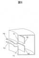
図1に、円形加速器39の外観、図2に円形加速器39の横断面の構成図、図3に円形加速器39の縦断面の構成図(図2のB-B’矢視図)を示す。 FIG. 1 shows the appearance of the
円形加速器39は上下方向に分割可能な主電磁石40によってその外殻を形成し、主電磁石40内部のビーム加速領域は真空引きされている。 The outer shell of the
主電磁石40の上部には主電磁石40に入射するためのイオンのビームを生成するイオン源53が設置されている。イオン源53で生成されたビームは、低エネルギービーム輸送系54を通り、上側の主磁極38の中心付近に設けられたイオン入射部52より主電磁石40内部のビーム加速領域に入射される。イオン源53としては、ECRイオン源などを適用できる。なお、イオン源53は、主電磁石40内部の真空引きされたビーム加速領域内部に配置しても良く、その場合はPIG型イオン源などが好適である。 An
主電磁石40は、主磁極38(図6参照)、ヨーク41、主コイル42からなる。ヨーク41は、主電磁石40の外観を形成し、内部におよそ円筒状の領域を構成する。主コイル42は、円環状のコイルであり、ヨーク41の内壁に沿って設置される。主コイル42は超電導コイルであり、主コイル42周囲にはクライオスタット60を設置して冷却する。主コイル42の内周側には主磁極38が上下対向して設置されている。主コイル42に電流を流すことにより励起され、主磁極38により形成される上下方向の磁場を、主磁場と呼ぶ。また、加速領域は、主磁場中のビームを加速するための領域いう。 The
ヨーク41には貫通口が複数ある。そのうち加速されたビームを出射するためのビーム用貫通口46、ヨーク41内部の種々のコイル導体を外部に引き出すためのコイル用貫通口48、真空引き用貫通口49、高周波加速空胴10のための高周波系用貫通口50が上下磁極の接続面に設けられている。 The
高周波加速空胴10は、λ/2共振型空胴であり、ディー電極12、ダミーディー電極13、内導体14、外導体15、回転コンデンサ30を有する。ディー電極12は、D字型の中空電極であり、内導体14とつながっている。ダミーディー電極13は、アース電位の電極であり、内導体14を外包する外導体15とつながっている。ダミーディー電極13の形状は、D字型の中空形状である必要はなく、ディー電極12との間に加速間隙11を形成する。 The high-
入力カプラ20は、高周波加速空胴10に高周波電力を供給するための機器であり、内導体14に対して静電結合式か磁気結合式により接続されている。加速高周波電源25より入力カプラ20に電力が供給され、入力カプラ20を通して外部より内導体14に対して高周波電力が供給される。これにより、ディー電極12とダミーディー電極13との間の加速間隙11にビームを加速するための高周波加速電圧、高周波加速電圧による高周波電場が発生する。 The
回転コンデンサ30は、高周波加速空胴10の共振周波数を変調するための機器であり、モータ31、固定電極32、固定電極32と対向する回転電極33とを含む。固定電極32は、内導体14上に形成されている。また、回転電極33は、外導体15に隣り合い、外導体15と物理的に接続されていないものの、外導体15と静電容量を介して電気的に接続されている。なお、固定電極32を外導体15上に形成し、回転電極33が内導体14に静電結合される構成でもよい。 The rotating
回転コンデンサ30は、回転電極33をモータ31で回転させることで、固定電極32と回転電極33との対向部面積を変化させ、固定電極32との間に形成される静電容量を時間的に変動させる。静電容量を時間的に変動させることで、高周波加速空胴10の共振周波数を変え、周波数変調パターンを形成する。回転コンデンサ30によって周波数変調された加速電圧が、ディー電極12とダミーディー電極13との間の加速間隙11に発生する。図2に示した加速間隙11は、ハーモニクス数1の場合、すなわち周回周波数と加速周波数とが同じ場合を示しており、ビームの軌道形状に応じて形成される。 The rotating
円形加速器39は、ビームを出射するための機器として、高周波キッカ70、セプタムコイル43、高エネルギービーム輸送系47とを有する。加速されたビームは、ビーム出射経路入口82から、加速領域の外に出射される。セプタムコイル43は、このビーム出射経路入口82に配置される。なお、セプタムコイル43は、ビーム進行方向に2つ以上に分割して配置してもよい。主電磁石40の内部から外部へ出射ビームを輸送するための高エネルギービーム輸送系47が、セプタムコイル43に続き、ビーム用貫通口46を通って、主電磁石40の外部にかけて配置されている。高周波キッカ70は、自身の内部を通過する周回ビームに高周波電圧を印加する機器である。セプタムコイル43は、ビームを水平方向外周側に偏向するためのコイルであり、コイル導体43-1とコイル導体43-2とを有する。セプタムコイル43は、加速領域とコイル導体43-1を隔てて接している。コイル導体43-1、43-2に電流を流すことにより、セプタムコイル43内部には、ビームの周回軌道に対して鉛直方向の磁場が発生する。この磁場により、セプタムコイル43内部に進行したビームは偏向され、高エネルギービーム輸送系47へと進んでいく。なお、セプタムコイル43は、鉄心などの磁性体コアを備えるものであってもよい。また、セプタムコイル43は、内部に入ったビームを高エネルギービーム輸送系47の方向に偏向できるのであれば、コイルを用いずに磁性体や永久磁石のみを用いたパッシブな構成で代替することもできる。 The
また、主電磁石40の内部には、2極磁場や多重極磁場からなる擾乱磁場であるピーラ磁場領域44とリジェネレータ磁場領域45とが形成される。ビーム出射には、高周波キッカ70、ピーラ磁場領域44、リジェネレータ磁場領域45、セプタムコイル43、および高エネルギービーム輸送系47を用いる。ビームの出射の詳細については、後述する。 Further, inside the main
ここで、円形加速器39でビームが入射されてから出射するまでのビームの動きについて簡単に説明する。 Here, the movement of the beam from the time when the beam is incident to the time when the beam is emitted by the
まず、イオン源53で生成された荷電粒子のビームは、低エネルギービーム輸送系54を通り、イオン入射部52より主電磁石40内部のビーム加速領域に入射される。入射されたビームは、高周波電場で加速され、エネルギーを増しながら主磁場中を周回する。ビームは加速されるにつれ、その軌道の曲率半径を増し、ビームは加速領域の中心から外側に向かって、螺旋状の軌道を描く。 First, the beam of the charged particles generated by the
ここで、ビーム加速領域内において、ビームが加速開始されて最大エネルギー(例えば、235MeV)になるまでに通る軌道を周回軌道と呼ぶ。周回軌道のうち、最大エネルギーのビームが通過する軌道を最大エネルギー軌道80と呼ぶ。また、周回軌道が螺旋を描く面を軌道面または軌道平面という。また、加速領域の中心を原点とする軌道面の2次元極座標系としたときの中心からの半径外側方向の軸をr軸とする。 Here, in the beam acceleration region, the orbit that the beam passes through from the start of acceleration to the maximum energy (for example, 235 MeV) is called an orbit. Of the orbits, the orbit through which the beam of maximum energy passes is called the
この周回の際に、ビームの荷電粒子は、ビームの軌道と直交する方向に振動しており、この振動をベータトロン振動、この振動の振動数をベータトロン振動数という。また、周回一周あたりの振動数をチューンといい、周回一周あたりの軌道面外側へのビームのr軸上変位をターンセパレーションという。また、周回するビームは、軌道面内かつビームの軌道と直交する方向のベータトロン振動を水平方向のベータトロン振動、チューンを水平方向チューンという。このベータトロン振動は、適切な高周波電圧を印加すると、共鳴が起こり振幅が急激に増大する性質がある。 During this orbit, the charged particles of the beam vibrate in the direction orthogonal to the trajectory of the beam, and this vibration is called betatron vibration, and the frequency of this vibration is called betatron frequency. The frequency per orbit is called tune, and the displacement of the beam to the outside of the orbital plane per orbit is called turn separation. As for the orbiting beam, the betatron vibration in the orbital plane and in the direction orthogonal to the orbit of the beam is called the horizontal betatron vibration, and the tune is called the horizontal tune. This betatron vibration has the property that resonance occurs and the amplitude increases sharply when an appropriate high-frequency voltage is applied.
主磁場は、周方向に主磁場強度を一定とするタイプのほか、AVF(Azimuthal Varying Field)タイプでもよいが、いずれの場合も主磁場分布は非等時性磁場であるから、式(1)で表されるn値が0より大きく、かつ1未満となるビーム安定化条件を満たす。 The main magnetic field may be an AVF (Azimuthal Variableing Field) type as well as a type in which the main magnetic field strength is constant in the circumferential direction. In either case, the main magnetic field distribution is a non-isochronous magnetic field. The beam stabilization condition that the n value represented by is larger than 0 and less than 1 is satisfied.

ここで、ρは設計軌道の偏向半径、Bは磁場強度、∂B/∂rは半径方向の磁場勾配である。上述のビーム安定化条件のもとでは、設計軌道から径方向に微小にずれたビームは設計軌道に戻すような復元力を受けると同時に、軌道面に対し鉛直な方向にずれたビームも軌道面に戻す方向に主磁場から復元力を受ける。すなわち、ビームは設計軌道の近傍をベータトロン振動し、ビームを安定に周回・加速できる。また、全エネルギーのビームで、軌道面内に平行、かつ軌道と直交する方向のベータトロン振動数(水平方向チューン)νrは1に近い値に設定される。Here, ρ is the deflection radius of the design orbit, B is the magnetic field strength, and ∂B / ∂r is the magnetic field gradient in the radial direction. Under the above-mentioned beam stabilization conditions, a beam that deviates slightly in the radial direction from the design orbit receives a restoring force that returns it to the design orbit, and at the same time, a beam that deviates in the direction perpendicular to the orbital plane also receives the orbital plane. Receives restoring force from the main magnetic field in the direction of returning to. That is, the beam vibrates in the vicinity of the design orbit with betatron, and the beam can stably orbit and accelerate. Further, in the beam of full energy, the betatron frequency (horizontal tune) νr in the direction parallel to the orbital plane and orthogonal to the orbital plane is set to a value close to 1.
上述の主磁場分布は、主磁極38、および主磁極38の表面に設置するトリムコイル(図示せず)や磁極片(図示せず)によって形成する。これら主磁場分布を形成する構成要素は、軌道平面に対し対称に配置するため、主磁場は軌道平面上においては、軌道平面と垂直な方向の磁場成分のみを持つ。 The above-mentioned main magnetic field distribution is formed by a main
この主磁場中でビームが最大エネルギーまで加速されると、加速間隙11にビームを加速するための高周波加速電圧が停止され、ビームは、最大エネルギー軌道80上を周回する。そして、最大エネルギー軌道80上に設置され、高周波を印加する高周波キッカ70にビームが入ると、高周波電圧が印加され、ビームのベータトロン振動振幅が増大する。 When the beam is accelerated to the maximum energy in this main magnetic field, the high frequency acceleration voltage for accelerating the beam is stopped in the
ベータトロン振動振幅が増大したビームは、やがて、最大エネルギー軌道80の外周側に、最大エネルギー軌道80からある距離を置いて設置されたピーラ磁場領域44とリジェネレータ磁場領域45とに到達する。ピーラ磁場領域44に到達したビームは、軌道面の外周側にキックされ、リジェネレータ磁場領域45に到達したビームは、軌道面内周側にキックされる。ここで、キックするとは、電場または磁場をかけることにより、ビームを偏向させることをいう。ピーラ磁場領域44の四極磁場成分によるキックで、ビームは、さらにベータトロン振動振幅を増大させ、ターンセパレーションは増大していく。同時に、リジェネレータ磁場領域45の磁場により、ビームの水平方向チューンが急激に変動しないようにしておき、ビームが出射されるまでの間に、水平方向と90度直交する垂直方向にベータトロン振動が発散してビームが失われるのを防ぐ。十分なターンセパレーションが得られると、セプタムコイル43にビームが入り、軌道面外側にキックされ、高エネルギービーム輸送系47を通り、円形加速器39の外側に出射される。 The beam with increased betatron vibration amplitude eventually reaches the peeler
ターンセパレーションの増大幅は、高周波キッカ70によるものより、ピーラ磁場領域44とリジェネレータ磁場領域45とによるもののほうがはるかに大きい。そのため、高周波キッカ70により印加する高周波電圧を調整することで、最大エネルギー軌道80上を周回するビームのうち、ピーラ磁場領域44とリジェネレータ磁場領域45とに到達するビームの量を調整することができる。すなわち、従来の円形加速器では、ビームは最大エネルギーに達したのち、出射電荷量の制御がなされることなく全て出射されていた。対して、高周波キッカ70への高周波印加をビーム出射途中で停止することで、ピーラ磁場領域44とリジェネレータ磁場領域45とにビームが到達しなくなり、円形加速器39からのビーム出射を中断できるようになる。高周波キッカ70に印加を再開することでビームの出射の再開もできる。また、高周波キッカ70に印加する電圧の強さや高周波の振幅、位相、周波数のいずれかを制御することで、円形加速器39から出射するビームの強さを制御することができる。さらに、従来の円形加速器では、イオン源におけるイオン生成量の時間変動や、加速高周波電場の時間的な安定性などにより、出射するビーム電荷量がパルスごとにばらついていた。対して、本技術では、高周波キッカ70に印加する電圧を調整することで、これらのビームの安定性に影響する要因を吸収し、出射ビームの電荷量を高精度に制御できる。 The increase width of the turn separation is much larger in the peeler
図4に、高周波キッカ70の断面構成を示す。また、図5に、図4中Cの方向より高周波キッカ70を見た鳥瞰図を示す。高周波キッカ70は、接地電極71と高圧電極72からなる。両電極は、最大エネルギー軌道80を挟むように、内周側に接地電極71、外周側に高圧電極72が対向して設置される。かつ、接地電極71と高圧電極72とは、軌道面内で軌道と直交する方向に高周波電場が作用するように形状、すなわち、接地電極71と高圧電極72とが、最大エネルギー軌道80のカーブにおおよそ平行な形状、に定める。接地電極71には金属製の突起部73を取り付け、接地電極71と高圧電極72との間に生じる高周波電場の集中を高めることもできる。高周波電圧が印加される高圧電極72は絶縁支持される。円筒状の加速領域の中で、ビームは該円筒の高さ方向真ん中付近に軌道平面を描く。接地電極71、高圧電極72共にビームが通過する軌道平面付近に通過孔を有する。この通過孔は、ビームのベータトロン振動による拡がりを考慮して、ビーム衝突が起きない程度の広さがよい。本実施例の高周波キッカ70は、図5に示すように端面が開いた形状であるが、ビーム通過孔を除いて端面を接地電極で閉塞し、共振器構造とすることもできる。高周波キッカ70は、最大エネルギー軌道80上に配置するのであればどこでもよいが、例えば図2に示すようにビーム出射経路入口82の近辺に配置する。 FIG. 4 shows a cross-sectional configuration of the
ピーラ磁場領域44と、リジェネレータ磁場領域45は、ビームに作用する多重極磁場が存在する領域である。この多重極磁場には少なくとも4極磁場成分が含まれ、4極以上の多極磁場、あるいは2極磁場が含まれていてもよい。ピーラ磁場領域44では、径方向外周側に向かって主磁場を弱める方向の磁場勾配となっており、リジェネレータ磁場領域45では逆に径方向外周側に向かって主磁場を強める方向の磁場勾配とする。なお、ピーラ磁場領域44としては、磁極端部の主磁場が減少する領域を利用することもできる。ピーラ磁場領域44と、リジェネレータ磁場領域45は、最大エネルギー軌道80の外周側に、ビーム出射経路入口82を挟んである方位角領域にそれぞれ配置される。また、高周波キッカ70によりベータトロン振動振幅が増大される前にピーラ磁場領域44またはリジェネレータ磁場領域45にビームが進行しないよう、ピーラ磁場領域44とリジェネレータ磁場領域45とは、最大エネルギー軌道80からベータトロン振動の共鳴前の振幅分よりも大きい幅を空けて外周側に配置されることが望ましい。また、ビーム進行方向に対して上流側にピーラ磁場領域44、下流側にリジェネレータ磁場領域45が配置されることが望ましいが、その逆でもよい。なお、図2では、ピーラ磁場領域44とリジェネレータ磁場領域45とを1つずつ設けているが、それぞれ、主磁場中に複数箇所に設けてもよい。 The peeler
ピーラ磁場領域44およびリジェネレータ磁場領域45の近辺には、磁性体製の複数の磁極片かコイル、あるいはその両者が非磁性材にて固定配置され、所望の多重極磁場を形成する。たとえば、ピーラ磁場領域44およびリジェネレータ磁場領域45のそれぞれについて、複数の磁極片で多重極磁場を、コイルで2極磁場を形成する。複数の磁極片とコイルは、近接配置させることも、空間的に離れた場所に配置することもできる。 A plurality of magnetic pole pieces or coils, or both, are fixedly arranged with a non-magnetic material in the vicinity of the peeler
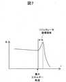
図6に、図1のA-A’矢視図であるリジェネレータ磁場領域45の磁極片配置例を示す。磁極片としては、リジェネレータ磁場領域45に磁場勾配を発生させる磁場勾配用シム36と、磁場勾配用シム36が最大エネルギー軌道80の内周側に発生させる不要磁場を打ち消すための磁場補正用シム37と、を用いる。また、図6はリジェネレータ磁場領域45を例に説明したが、ピーラ磁場領域44についても、ピーラ磁場領域44も磁場勾配を発生させる磁場勾配用シム36と、磁場勾配用シム36が最大エネルギー軌道80の内周側に発生させる不要磁場を打ち消すための磁場補正用シム37と、を用いる。 FIG. 6 shows an example of arrangement of magnetic pole pieces in the regenerator
図7は、図6中r軸上の主磁場の分布を示す。最大エネルギー軌道80までは、磁場勾配∂B/∂rがわずかに下がっており、式(1)のn値が安定化条件を満たし、ビームが安定に周回する。しかし、リジェネレータ磁場領域45では、磁場勾配が急激に上昇しており、ビームが安定せず、軌道面内周側にキックされる。また、ピーラ磁場領域44では、リジェネレータ磁場領域45とは逆に、磁場勾配が急激に下降しており、ピーラ磁場領域44でも、ビームは安定せず、軌道面外周側にキックされる。 FIG. 7 shows the distribution of the main magnetic field on the r-axis in FIG. Up to the
なお、高周波キッカ70によるベータトロン振動振幅の増大幅は、ピーラ磁場領域44とリジェネレータ磁場領域45とによるベータトロン振動振幅の増大幅よりも小さいが、ピーラ磁場領域44とリジェネレータ磁場領域45とを設けなくても、高周波キッカ70によるベータトロン振動振幅の増大効果により、ビームの出射は可能である。 The increase width of the betatron vibration amplitude by the
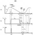
図8は、ビームの出射手順について説明する図である。図8(a)は、高周波加速空胴10の共振周波数fcavと高周波キッカ70によりビームに印加される高周波電場の周波数である高周波キッカ周波数fevtと、時刻Tとの関係を表すグラフである。図8(b)は、加速間隙11に発生する加速電圧Vaccと高周波キッカ70に印加される高周波キッカ電圧Vextと、時刻Tとの関係を表すグラフである。図8(c)は、入射するビームの電流と出射するビームの電流と、時刻Tとの関係を表すグラフである。FIG. 8 is a diagram illustrating a beam emission procedure. FIG. 8A is a graph showing the relationship between the resonance frequency fcav of the high
一加速周期は、加速電圧Vaccの立ち上がり(時刻T1)から始まる。その後、加速電圧Vaccが十分に上がると、イオン源53よりビームが入射される(時刻T2)。ビームが入射してから時間t1経過後にビームの高周波捕獲が終了する。捕獲されたビーム、すなわち入射されたビームのうち加速の準備が整ったビームが加速電圧Vaccにより加速され始める(時刻T3)。ビームが最大エネルギーである235MeVに達すると、加速高周波の遮断が開始され(時刻T4)、それから時間t2が経過すると加速高周波電圧VaccがOFF状態となる。それと同時に、高周波キッカ70へ高周波電圧Vextの印加が開始される(時刻T5)。なお、高周波キッカ70への高周波キッカ70へ高周波電圧Vextの印加開始(時刻T5)は、加速高周波電圧VaccがOFF状態となるのと厳密に同時でなくてもよい。高周波電圧Vextの印加開始は、加速高周波の遮断開始(時刻T4)の直前や同時、直後でもよく、加速高周波電圧VaccがOFF状態の直前や直後でもよい。One acceleration cycle starts from the rising edge of the acceleration voltageVac (time T1). After that, when the acceleration voltageVac rises sufficiently, a beam is incident from the ion source 53 (time T2). High-frequency capture of the beam ends after a lapse of time t1 after the beam is incident. The captured beam, that is, the incident beam that is ready for acceleration, begins to be accelerated by the acceleration voltageVacc (time T3). When the beam reaches the maximum energy of 235 MeV, the cutoff of the accelerated high frequency is started (time T4), and when the time t2 elapses, the accelerated high frequency voltageVacc is turned off. At the same time, the application of the high frequency voltageVext to the
高周波キッカ70の高周波電圧は、高周波キッカ70が共振器構造でなく、静電容量が適切な値となるように設計されていれば、数μsの応答で素早く立ち上がる。ここで、ベータトロン振動は、チューン又はチューンの小数部のいずれか一方とビームの周回周波数との積が、印加される高周波電圧の周波数と略同一であるとき、振幅が共鳴的に増大する性質をもつ。そこで、該高周波電圧の周波数fextは、最大エネルギービームの水平方向チューンνrの小数部Δνrと、最大エネルギービームの周回周波数frevとの積Δνr×frevと略同一となるようにしておく。その結果、水平方向ベータトロン振動の振幅は共鳴的に増大し続け、やがてピーラ磁場領域44とリジェネレータ磁場領域45にビームが到達する(時刻T6)。なお、周波電圧の周波数fextが、最大エネルギービームの水平方向チューンνrと、最大エネルギービームの周回周波数frevとの積νr×frevと等しくなるようにしてもよい。The high-frequency voltage of the high-
ビームは、ピーラ磁場領域44を通過すると外周側にキックされ、リジェネレータ磁場領域45を通過すると逆に内周側にキックされる。ピーラ磁場領域44、リジェネレータ磁場領域45共に径方向に磁場勾配を有するので、複数回ビームが周回するうちに、キック量が次第に増えていき、ターンセパレーションが増大する。つまり、2νr=2のベータトロン振動の共鳴条件を利用することで、ターンセパレーションを増大させることができる。When the beam passes through the peeler
ビーム出射経路入口82にはセプタムコイル43が設置されている。やがてセプタムコイル43の内周側に設置されるコイル導体43-1の厚みを大きく超えるターンセパレーションが得られるようになると、ビームは、セプタムコイル43内部へと導かれ、十分な偏向を受け高エネルギービーム輸送系47へ導かれ、出射される。 A
なお、高周波キッカ70へ高周波電圧印加を開始した直後(時刻T5)は、可能な限り大きな高周波電圧を印加し、ビームの振幅を素早く増大させることで、ビーム出射までの時間を短縮できる。そして、ビームがピーラ磁場領域44またはリジェネレータ磁場領域45に到達する直前(時刻T6)に高周波電圧を低下させ、ピーラー磁場領域44とリジェネレータ磁場領域45とに進行するビームの量を調整することで、ビーム出射電流を細かく制御することができる。高周波電圧Vextを低下させるかわりに、高周波キッカ70に印加する高周波の周波数をスイープする、あるいは該高周波の位相を変えることでも、ビームの出射電流を変えることができる。これは、ビームに含まれる荷電粒子のベータトロン振動数が、ある分布をもってばらついているという性質(チューンスプレッド)を利用している。高周波の周波数を変えることにより、共鳴を起こす荷電粒子の振動数の分布のどの帯域に合わせるかで、ビームの出射電流を変えることができる。また、高周波電圧Vaccを低下させるかわりに、遮断してもよい。Immediately after starting the application of the high frequency voltage to the high frequency kicker 70 (time T5), the high frequency voltage as large as possible is applied to quickly increase the amplitude of the beam, so that the time until the beam is emitted can be shortened. Then, the high frequency voltage is lowered immediately before the beam reaches the peeler
そして、ビームの出射開始(時刻T6)から時間t4経過後に高周波キッカ70へ高周波電圧Vextの印加を停止することで、ビームの出射を停止させる(時刻T7)。この時間t4を調整することでビームの出射時間を制御することができる。Then, after the lapse of time t4 from the start of beam emission( time T6), the application of the high frequency voltageVext to the
高周波キッカ70に引加する高周波電圧を制御することで、ビーム出射電流を調整することができ、該高周波電圧を印加停止すればビーム出射を停めることができるので、スキャニング照射で要求されるスポット線量を、1回の出射パルスビームで過不足なく照射することができ、線量率が向上する。例えば、図8に示すようにビームの出射開始(時刻T6)から時間t4’経過後まで高周波キッカ70への高周波電圧Vextの印加を続ければ、時刻T7’までビームを出射することができる。The beam emission current can be adjusted by controlling the high frequency voltage applied to the
また、出射後に加速器内に周回するビームが残存していれば、該高周波電圧Vextを再び印加することでビーム出射を再開でき(時刻T8)、再びビームを入射・捕獲・加速することなしに次のスポット照射に用いることができる。すなわち、一加速周期内に複数回ビームを出射することができるので、イオン源53より入射された電荷を無駄なく使用できるため、線量率がさらに向上する。そして、再び、加速電圧Vaccが立ち上がり始めれば、新たな加速周期が始まる(時刻T10)。Further, if the orbiting beam remains in the accelerator after emission, the beam emission can be restarted by applying the high frequency voltageVext again (time T8), without incident, capturing, or accelerating the beam again. It can be used for the next spot irradiation. That is, since the beam can be emitted a plurality of times within one acceleration cycle, the electric charge incident from the
図9に、以上の出射方法を実現する高周波電源と制御系のブロック図を示す。加速高周波電源25は、カソード抵抗22、プレート電源23、三極管24を有する。高周波キッカ電源86は、プレート電源26、三極管24、グリッドバイアス電源89、前段増幅器94を有する。図9は加速高周波電源25、高周波キッカ電源86共に三極管を用いた場合の構成であるが、そのほかに四極管や半導体増幅器を用いてもよい。 FIG. 9 shows a block diagram of a high-frequency power supply and a control system that realizes the above emission method. The accelerating high
加速高周波電源25は、自励発振式とし、ピックアップループ21にて加速高周波の一部をカソード回路に帰還させる方式とする。高周波加速電圧は、プレート電源23の出力電圧を高速に変調することで制御する。カソードバイアス電位は、図9に示したようにカソード抵抗22でプレート電位を分圧する形で与えるか、あるいはカソード電源を用いて与える。 The accelerating high
原発振器92は、高周波キッカ70用に、ある周波数帯域の信号を生成する。ここで、原発振器92の信号には、ビームのチューンスプレッド分と、高周波キッカ70への高周波電圧印加中に水平方向チューンが変動することを考慮し、必要な周波数帯成分が含まれるものとする。該信号はスイッチ93を経て前段増幅器94にて増幅されたのち、三極管24で増幅され、高周波キッカ70に供給される。高周波キッカ70の高周波電圧は、前段増幅器94の利得を変えるか、あるいはプレート電源26の出力電圧を高速に変調することで制御する。 The
演算装置91は、回転コンデンサ30の角度検出機構90か、あるいは加速高周波のピックアップ信号から検出する加速高周波の周波数変調パターンと、各照射スポットへの要求線量をもとに、加速高周波のON/OFFタイミングと電圧振幅、それと高周波キッカ70のON/OFFタイミングと電圧振幅を制御する。 The
また、加速器内部に残存する周回電荷量をモニタするために、最大エネルギー軌道80上のどこかに、静電的あるいは磁気的にビーム電荷量を検出するビームモニタが設置される。そして、周回電荷量があるレベル以下に減少したら、演算装置91は再度、加速電圧の印加を開始し、捕獲・加速・取出しの加速周期を繰り返す。 Further, in order to monitor the amount of orbital charge remaining inside the accelerator, a beam monitor that electrostatically or magnetically detects the amount of beam charge is installed somewhere on the
図10に、粒子線治療システムの全体構成を示す。図10において、粒子線治療システムは、円形加速器39、回転ガントリ190、スキャニングコイルを含む照射装置192、治療台201およびそれらを制御する制御装置191からなる。円形加速器39から出射されたビームは、回転ガントリ190により照射装置192まで輸送される。輸送されたイオンビームは照射装置192、およびビームエネルギーの調整により患部形状に合致するように整形され、治療台201に横たわる患者200の患部標的に対して所定量照射される。照射装置192は、線量モニタを内包しており、患者200への照射スポット毎に照射された線量を監視している。この線量データを元に、制御装置191は各照射スポットへの要求線量を計算して、図9の演算装置91への入力データとする。 FIG. 10 shows the overall configuration of the particle beam therapy system. In FIG. 10, the particle beam therapy system includes a
以上が実施例1の説明である。本実施例により、高周波キッカ70での高周波印加を途中で停止することで、ピーラ磁場領域44とリジェネレータ磁場領域45とにビームが到達しなくなり、ビームの円形加速器39から出射の中断ができるようになる。高周波キッカ70に印加を再開することで、再びビームを入射・捕獲・加速することなしにビームの出射の再開もできる。また、高周波キッカ70に印加する電圧の強さや高周波の振幅、位相、周波数のいずれかを制御することで、円形加速器39から出射するビームの強さを制御することができる。さらに、高周波キッカ70に印加する電圧を調整することで、ビームの安定性に影響する要因を吸収し、安定したビームを出射することができる。 すなわち、出射に用いる高周波により、1加速周期ごとの出射ビーム電荷を高精度に制御できるため、スキャニングに適した線量制御が可能となる。そのため、線量率が増加し、照射時間を短くでき、粒子線治療システムの患者スループットを向上させることができる。 The above is the description of the first embodiment. According to this embodiment, by stopping the high frequency application in the
実施例2の円形加速器について説明する。本実施例のうち、実施例1と同じ構成については説明を省略し、異なる構成ついてのみ説明する。 The circular accelerator of the second embodiment will be described. Of the present embodiments, the same configuration as that of the first embodiment will be omitted, and only different configurations will be described.
本実施例では、ビームエネルギーを70MeVから235MeVの間で任意に変えて加速器より出射できるようにするため、ビーム軌道をビーム出射経路入口82の側に偏芯させるように主磁場を形成した偏芯軌道型加速器を用いる。 In this embodiment, an eccentricity in which a main magnetic field is formed so as to eccentric the beam trajectory toward the beam
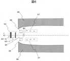
図11に、偏芯軌道型加速器の断面構成を示す。図2からの構造上の変更点として、ディー電極12、ダミーディー電極13の形状、及びその間に形成される加速間隙11の形状が挙げられる。ここで、回転コンデンサ30の回転軸と加速領域の円の中心を通る線を中心線とする。イオン入射部52は中心線上で加速領域の中心よりもビーム出射経路入口82側に配置されている。また、図示はしないが、後述する磁場を形成するために主磁極38の上下対向する面の形状も実施例1と大きく異なる。高周波キッカ70の構成も図13に示すように異なる。 FIG. 11 shows a cross-sectional configuration of an eccentric orbital accelerator. Structural changes from FIG. 2 include the shapes of the
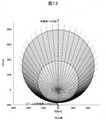
図12に、各エネルギーの軌道を示し、偏芯軌道の実現方法を説明する。周回軌道は最大エネルギー235MeVから磁気剛性率0.04Tmおきに50種類のエネルギーの軌道を実線で示している。点線は各軌道の同一の周回位相を結んだ線であり、等周回位相線と呼ぶ。等周回位相線は集約領域から周回位相π/20ごとにプロットしている。ディー電極12と対向するダミーディー電極13の間に形成される加速間隙11は、等周回位相線に沿って設置される。より具体的には、ディー電極12は同心軌道の中心付近を先端とし、半径が等周回位相線に沿う、扇形のような中空の形状をしている。また、ダミーディー電極13は、ディー電極12に対向する形状をしている。 FIG. 12 shows the orbits of each energy and explains how to realize the eccentric orbits. The orbits show 50 types of energy orbits with solid lines every 0.04 Tm of magnetic rigidity from the maximum energy of 235 MeV. The dotted line is a line connecting the same orbital phases of each orbit, and is called an equal orbital phase line. The equal-circulation phase line is plotted every orbital phase π / 20 from the aggregation region. The
ビームのエネルギーが低い領域では、サイクロトロン同様にイオンの入射部52付近を中心とする同心軌道に近くなるが、より大きなエネルギーの軌道はビーム出射経路入口82の付近で密に集約しており、逆に内導体14の付近では各エネルギーの軌道が互いに離れた位置関係にある。この軌道が密に集まっている点を集約領域、離散した領域を離散領域と呼ぶ。このような軌道配置とし、集約領域付近からビームを取出すことで、必要となるビームキック量を小さくでるため、エネルギー可変のビーム出射を容易にすることができる。 In the region where the energy of the beam is low, it becomes close to the concentric orbitals centered on the vicinity of the
上記のような軌道構成と軌道周辺での安定な振動を生じさせるために、本実施例の加速器では、径方向外周側に行くにつれ主磁場が小さくなる分布を、主磁極38の形状と、その表面に設置するトリムコイルや磁極片により形成する。また、設計軌道に沿った線上では主磁場は一定値である。よって、設計軌道は円形となる。 In order to generate the above-mentioned orbital configuration and stable vibration around the orbit, the accelerator of this embodiment has a distribution in which the main magnetic field becomes smaller toward the outer peripheral side in the radial direction, the shape of the main
次にビームの出射方法について説明する。ビームの出射には、すべての出射エネルギーのビーム軌道が集約している集約領域付近に設置する高周波キッカ70と、その両脇に配置するピーラ磁場領域44、リジェネレータ磁場領域45、そしてセプタムコイル43と高エネルギービーム輸送系47を用いる。本実施例では、出射に用いる上記要素のうち、高周波キッカ70の構成が実施例1と異なる。 Next, a method of emitting a beam will be described. For beam emission, a high-
図13に、本実施例の高周波キッカ70の断面構成を示す。高周波キッカ70は、実施例1と同じく接地電極71と突起部73、高圧電極72で構成されるが、接地電極71と高圧電極72は、最大エネルギー軌道80と最低出射エネルギー軌道81とが挟まれるように配置される。かつ、それぞれの軌道と軌道面内で直交する方向と近い向きに高周波電場が作用するように、接地電極71と高圧電極72との形状が定められる。すなわち接地電極71と高圧電極72が、最低出射エネルギー軌道81と最大エネルギー軌道80とのカーブに沿っておおよそ平行に並ぶ形状となる。ここで、最低出射エネルギー軌道81とは、円形加速器39から出射できる最低エネルギー(例えば、70MeV)のビームが通過する軌道である。なお、突起部73は省略してもよい。 FIG. 13 shows a cross-sectional configuration of the
ビームの出射手順は、基本的に実施例1で説明したものと同一であるが、加速高周波電圧Vaccを遮断するタイミング(時刻T4)と高周波キッカ70へ高周波電圧Vextの印加開始のタイミング(時刻T5)とを前にずらせば、任意のエネルギーのビームが出射できるようになる。言い換えると、加速したビームが所望のエネルギーに達したタイミングで、加速高周波電圧Vaccの遮断を開始する(時刻T4)ことで、ビームの加速が中断される。そして、高周波電圧Vextを印加開始することで(時刻T5)、その所望のエネルギーのビームのベータトロン振動の振幅が高周波キッカ70により増大される。やがて、そのビームがピーラ磁場領域44とリジェネレータ磁場領域45とに到達し、出射される。The beam emission procedure is basically the same as that described in the first embodiment, but the timing at which the accelerated high frequency voltageVacc is cut off (time T4) and the timing at which the high frequency voltageVext is started to be applied to the high frequency kicker 70 (time T4). By shifting the time T5) forward, a beam of arbitrary energy can be emitted. In other words, when the accelerated beam reaches the desired energy, the acceleration of the beam is interrupted by starting the cutoff of the accelerated high frequency voltageVac (time T4). Then, by starting to apply the high frequency voltageVext (time T5), the amplitude of the betatron vibration of the beam of the desired energy is increased by the
また、セプタムコイル43、および高エネルギービーム輸送系47に配置する光学パラメータ調整用のコイルは、出射するビームエネルギーに応じて励磁電流を変える必要がある。よってこれらのコイルについては、空芯構造か積層鋼板コアを用い、1ターンから数ターン程度のコイルにパルス通電する構成とする。セプタムコイル43は、ビーム進行方向に2つ以上に分割して配置してもよい。 Further, the
以上が実施例2の説明である。実施例2に記載によれば、実施例1と同様の効果を奏することができる。さらに、以上のような構成とすることで、本発明の円形加速器39は、ディグレーダ不要で可変エネルギーのビーム出射ができるため、取出し時に失われるビーム電流値を最小限に留めることができ、ビーム利用効率が高くなり、実施例1よりもさらに高い線量率を実現できる。また、電気的に出射エネルギーを変更できるため、ディグレーダを機械的に移動する方式よりもエネルギー切替えに要する時間が短いという利点も有する。 The above is the description of the second embodiment. According to the description in Example 2, the same effect as in Example 1 can be obtained. Further, with the above configuration, the
10…高周波加速空胴
11…加速間隙
12…ディー電極
13…ダミーディー電極
14…内導体
15…外導体
20…入力カプラ
21…ピックアップループ
22…カソード抵抗
23…プレート電源
24…三極管
25…加速高周波電源
26…プレート電源
30…回転コンデンサ
31…モータ
32…固定電極
33…回転電極
36…磁場勾配用シム
37…磁場補正用シム
38…主磁極
39…円形加速器
40…主電磁石
41…ヨーク
42…主コイル
43…セプタムコイル
44…ピーラ磁場領域
45…リジェネレータ磁場領域
46…ビーム用貫通孔
47…高エネルギービーム輸送系
48…コイル用貫通孔
49…真空引き用貫通孔
50…高周波系用貫通孔
52…イオン入射部
53…イオン源
54…低エネルギービーム輸送系
60…クライオスタット
70…高周波キッカ
71…接地電極
72…高圧電極
73…突起部
80…最大エネルギー軌道
81…最低出射エネルギー軌道
82…ビーム出射経路入口
86…高周波キッカ電源
89…グリッドバイアス電源
90…角度検出機構
91…演算装置
92…原発振器
93…スイッチ
94…前段増幅器
190…回転ガントリ
191…制御装置
192…照射装置
200…患者
201…治療台10 ... High
Claims (20)
Translated fromJapanese前記第1の高周波とは周波数の異なる第2の高周波を、前記円形加速器内部の前記荷電粒子ビームの軌道の集約領域、または前記荷電粒子ビームの最大エネルギー軌道上で印加することにより、前記荷電粒子ビームを出射することを特徴とする円形加速器。In a circular accelerator that accelerates a charged particle beam while increasing the orbital radius by applying a first high frequency in the main magnetic field.
The charged particles are applied by applying a second high frequency having a frequency different from that of the first high frequency in the aggregation region of the orbit of the charged particle beam inside the circular accelerator or on the maximum energy orbit of the charged particle beam. A circular accelerator characterized by emitting a beam.
前記円形加速器は、前記第2の高周波を印加する高圧電極と接地電極とを有し、
前記高圧電極と前記接地電極とは、所望のエネルギーまで加速された前記荷電粒子ビームが通過する軌道をはさんで設置される
ことを特徴とする円形加速器。In the circular accelerator according to claim 1,
The circular accelerator has a high-voltage electrode to which the second high frequency is applied and a ground electrode.
The high-voltage electrode and the ground electrode are circular accelerators characterized in that they are installed across an orbit through which the charged particle beam accelerated to a desired energy passes.
前記第2の高周波は、前記荷電粒子ビームの軌道面内かつ前記荷電粒子ビームの軌道と直交する方向である水平方向のベータトロン振動の振幅を増大させる周波数である
ことを特徴とする円形加速器。In the circular accelerator according to claim2 ,
The second high frequency is a circular accelerator having a frequency that increases the amplitude of horizontal betatron vibration in the orbital plane of the charged particle beam and in a direction orthogonal to the orbit of the charged particle beam.
前記第2の高周波は、水平方向の前記ベータトロン振動の振動数又は前記振動数の小数部のいずれか一方と、前記所望のエネルギーの前記荷電粒子ビームの周回周波数と、の積と略同一である第1の周波数成分を含む
ことを特徴とする円形加速器。In the circular accelerator according to claim 3,
The second high frequency is substantially the same as the product of either the frequency of the betatron vibration in the horizontal direction or the fractional part of the frequency and the orbital frequency of the charged particle beam of the desired energy. A circular accelerator characterized by containing a first frequency component.
前記第2の高周波は、前記第1の周波数成分とは異なる複数の第2の周波数成分を含むことを特徴とする円形加速器。In the circular accelerator according to claim 4,
The second high frequency is a circular accelerator characterized by containing a plurality of second frequency components different from the first frequency component.
前記第2の周波数成分は、前記荷電粒子ビームのチューンの変動、及び/または、ばらつきを考慮した値である
こと特徴とする円形加速器。In the circular accelerator according to claim 5,
A circular accelerator characterized in that the second frequency component is a value in consideration of variation and / or variation in the tune of the charged particle beam.
2極以上の極数の磁場成分と、少なくとも4極磁場成分を含む多重極磁場が存在する磁場領域が、前記主磁場中に少なくとも2箇所ある
ことを特徴とする円形加速器。In the circular accelerator according to any one of claims 1 to 6.
A circular accelerator characterized in that there are at least two magnetic field regions in the main magnetic field in which a magnetic field component having a number of poles of two or more poles and a multipolar magnetic field including at least a quadrupole magnetic field component exist.
前記磁場領域に含まれる4極以上の極数の多重極磁場成分が、径方向外周側に向かって前記主磁場が強くなる磁場勾配を有する第1の磁場領域である
ことを特徴とする円形加速器。In the circular accelerator according to claim 7,
A circular accelerator characterized in that a multipolar magnetic field component having four or more poles included in the magnetic field region is a first magnetic field region having a magnetic field gradient in which the main magnetic field becomes stronger toward the radial outer peripheral side. ..
前記磁場領域に含まれる4極以上の極数の多重極磁場成分が、径方向外周側に向かって前記主磁場が弱くなる磁場勾配を有する第2の磁場領域である
ことを特徴とする円形加速器。In the circular accelerator according to claim 8,
A circular accelerator characterized in that a multipolar magnetic field component having four or more poles included in the magnetic field region is a second magnetic field region having a magnetic field gradient in which the main magnetic field weakens toward the radial outer peripheral side. ..
前記第1および前記第2の磁場領域が、前記荷電粒子ビームが加速中に周回する軌道より外周側に存在する
ことを特徴とする円形加速器。In the circular accelerator according to claim 9,
A circular accelerator characterized in that the first and second magnetic field regions are located on the outer peripheral side of the orbit around which the charged particle beam orbits during acceleration.
前記荷電粒子ビームが所望のエネルギーまで加速されると、前記第1の高周波を遮断し、前記第2の高周波を立ちあげることを特徴とする円形加速器。In the circular accelerator according to any one of claims 9 or 10.
A circular accelerator characterized in that when the charged particle beam is accelerated to a desired energy, the first high frequency is blocked and the second high frequency is raised.
前記出射に用いる高周波の印加開始後にビームが前記第1の磁場領域または前記第2の磁場領域に達する前に、前記第2の高周波の電圧を低下させるか、又は遮断するように制御することを特徴とする円形加速器。In the circular accelerator according to claim 11,
Controlling the voltage of the second high frequency to be reduced or cut off before the beam reaches the first magnetic field region or the second magnetic field region after the start of application of the high frequency used for the emission. A characteristic circular accelerator.
前記第2の高周波の印加時間を変える、又は、前記第2の高周波を遮断後に再度印加することを特徴とする円形加速器。In the circular accelerator according to claim 12,
A circular accelerator characterized in that the application time of the second high frequency is changed, or the second high frequency is cut off and then applied again.
前記第2の高周波の周波数をスイープするすることを特徴とする円形加速器。In the circular accelerator according to any one of claims 1 to 13.
A circular accelerator characterized by sweeping the second high frequency frequency.
前記円形加速器は、
前記主磁場を形成し、対向して配置される主磁極を含む主電磁石と、
前記主磁極間に前記荷電粒子ビームを入射するイオン源と、
前記主磁極間に配置され、前記第1の高周波が印加される加速間隙と、
前記主磁場中から前記円形加速器の外部に前記荷電粒子ビームを出射する出射経路と、
を備え、
前記加速間隙は、前記第1の高周波を周波数変調することを特徴とする円形加速器。In the circular accelerator according to claim 1 to 14,
The circular accelerator
A main electromagnet including a main magnetic pole that forms the main magnetic field and is arranged opposite to each other.
An ion source that incidents the charged particle beam between the main magnetic poles,
An acceleration gap arranged between the main magnetic poles and to which the first high frequency is applied, and
An emission path for emitting the charged particle beam from the main magnetic field to the outside of the circular accelerator.
Equipped with
The acceleration gap is a circular accelerator characterized in that the first high frequency is frequency-modulated.
前記円形加速器は、
前記主磁場を形成し、対向して配置される主磁極を含む主電磁石と、
前記主磁極間に前記荷電粒子ビームを入射するイオン源と、
前記主磁極間に配置され、前記第1の高周波が印加される加速間隙と、
前記主磁場中から前記円形加速器の外部に前記荷電粒子ビームを出射する出射経路と、
を備え、
前記荷電粒子ビームの周回する軌道が、ある一方向に偏芯していることを特徴とする円
形加速器。In the circular accelerator according to any one of claims 1 to 14.
The circular accelerator
A main electromagnet including a main magnetic pole that forms the main magnetic field and is arranged opposite to each other.
An ion source that incidents the charged particle beam between the main magnetic poles,
An acceleration gap arranged between the main magnetic poles and to which the first high frequency is applied, and
An emission path for emitting the charged particle beam from the main magnetic field to the outside of the circular accelerator.
Equipped with
A circular accelerator characterized in that the orbit around the charged particle beam is eccentric in a certain direction.
前記第1の高周波とは周波数の異なる第2の高周波を、前記円形加速器内部の前記荷電粒子ビームの軌道の集約領域、または前記荷電粒子ビームの最大エネルギー軌道上で印加することにより、前記荷電粒子ビームを出射することを特徴とする円形加速器の運転方法。It is a method of operating a circular accelerator that accelerates a charged particle beam while increasing the orbital radius by applying a first high frequency in a main magnetic field.
The charged particles are applied by applying a second high frequency having a frequency different from that of the first high frequency in the aggregation region of the orbit of the charged particle beam inside the circular accelerator or on the maximum energy orbit of the charged particle beam. A method of operating a circular accelerator, which is characterized by emitting a beam.
前記円形加速器は、前記第2の高周波を印加する高圧電極と接地電極とを有し、
前記高圧電極と前記接地電極とは、所望のエネルギーまで加速された前記荷電粒子ビームが通過する軌道をはさんで設置される
ことを特徴とする円形加速器の運転方法。In the method of operating a circular accelerator according to claim 18,
The circular accelerator has a high-voltage electrode to which the second high frequency is applied and a ground electrode.
A method of operating a circular accelerator, wherein the high-voltage electrode and the ground electrode are installed across an orbit through which the charged particle beam accelerated to a desired energy passes.
前記第2の高周波は、前記荷電粒子ビームの軌道面内かつ前記荷電粒子ビームの軌道と直交する方向である水平方向のベータトロン振動の振幅を増大させる周波数である
ことを特徴とする円形加速器の運転方法。In the method of operating a circular accelerator according to any one of claims 18 or 19.
The second high frequency is a frequency that increases the amplitude of horizontal betatron vibration in the orbital plane of the charged particle beam and in a direction orthogonal to the orbit of the charged particle beam. how to drive.
Priority Applications (5)
| Application Number | Priority Date | Filing Date | Title |
|---|---|---|---|
| JP2018012145AJP7002952B2 (en) | 2018-01-29 | 2018-01-29 | A circular accelerator, a particle beam therapy system equipped with a circular accelerator, and how to operate the circular accelerator |
| PCT/JP2018/041159WO2019146211A1 (en) | 2018-01-29 | 2018-11-06 | Circular accelerator, particle beam therapy system equiped with circular accelerator, and circular accelerator operation method |
| US16/761,307US11570881B2 (en) | 2018-01-29 | 2018-11-06 | Circular accelerator, particle therapy system with circular accelerator, and method of operating circular accelerator |
| CN201880070623.2ACN111279801B (en) | 2018-01-29 | 2018-11-06 | Circular accelerator, particle beam therapy system provided with circular accelerator, and operation method of circular accelerator |
| US18/062,056US11849533B2 (en) | 2018-01-29 | 2022-12-06 | Circular accelerator, particle therapy system with circular accelerator, and method of operating circular accelerator |
Applications Claiming Priority (1)
| Application Number | Priority Date | Filing Date | Title |
|---|---|---|---|
| JP2018012145AJP7002952B2 (en) | 2018-01-29 | 2018-01-29 | A circular accelerator, a particle beam therapy system equipped with a circular accelerator, and how to operate the circular accelerator |
Publications (3)
| Publication Number | Publication Date |
|---|---|
| JP2019133745A JP2019133745A (en) | 2019-08-08 |
| JP2019133745A5 JP2019133745A5 (en) | 2020-08-27 |
| JP7002952B2true JP7002952B2 (en) | 2022-01-20 |
Family
ID=67395395
Family Applications (1)
| Application Number | Title | Priority Date | Filing Date |
|---|---|---|---|
| JP2018012145AActiveJP7002952B2 (en) | 2018-01-29 | 2018-01-29 | A circular accelerator, a particle beam therapy system equipped with a circular accelerator, and how to operate the circular accelerator |
Country Status (4)
| Country | Link |
|---|---|
| US (2) | US11570881B2 (en) |
| JP (1) | JP7002952B2 (en) |
| CN (1) | CN111279801B (en) |
| WO (1) | WO2019146211A1 (en) |
Families Citing this family (20)
| Publication number | Priority date | Publication date | Assignee | Title |
|---|---|---|---|---|
| JP7002952B2 (en)* | 2018-01-29 | 2022-01-20 | 株式会社日立製作所 | A circular accelerator, a particle beam therapy system equipped with a circular accelerator, and how to operate the circular accelerator |
| JP2019200899A (en)* | 2018-05-16 | 2019-11-21 | 株式会社日立製作所 | Particle beam accelerator and particle beam therapy system |
| JP7207712B2 (en)* | 2019-01-18 | 2023-01-18 | 国立研究開発法人日本原子力研究開発機構 | Charged particle beam manipulation device, charged particle beam accelerator, and charged particle beam manipulation method |
| EP3876679B1 (en) | 2020-03-06 | 2022-07-20 | Ion Beam Applications | Synchrocyclotron for extracting beams of various energies and related method |
| JP2022006663A (en)* | 2020-06-24 | 2022-01-13 | 株式会社日立製作所 | Particle beam therapy system and control method thereof |
| JP7425711B2 (en) | 2020-10-21 | 2024-01-31 | 株式会社日立製作所 | Accelerator and particle therapy systems |
| JP7485593B2 (en)* | 2020-12-14 | 2024-05-16 | 株式会社日立製作所 | Accelerators and particle beam therapy equipment |
| JP7465042B2 (en)* | 2021-01-15 | 2024-04-10 | 株式会社日立製作所 | Circular accelerator and particle beam therapy system |
| JP7612495B2 (en) | 2021-04-19 | 2025-01-14 | 株式会社日立ハイテク | Magnetic pole forming method, magnetic field adjusting device, accelerator and particle beam therapy system |
| JP7634441B2 (en)* | 2021-08-03 | 2025-02-21 | 株式会社日立ハイテク | Circular accelerator and particle therapy system |
| JP7595544B2 (en) | 2021-09-09 | 2024-12-06 | 株式会社日立ハイテク | Rotating condenser, circular accelerator and particle beam therapy system |
| JP2023084781A (en) | 2021-12-08 | 2023-06-20 | 株式会社日立製作所 | Circular accelerator and particle beam therapy system |
| JP7631178B2 (en)* | 2021-12-13 | 2025-02-18 | 株式会社日立ハイテク | Accelerator, particle beam therapy system and control method |
| JP7671708B2 (en) | 2022-03-02 | 2025-05-02 | 株式会社日立ハイテク | Accelerators and particle beam therapy equipment |
| JP2024006197A (en)* | 2022-07-01 | 2024-01-17 | 株式会社日立製作所 | Accelerator and particle beam therapy equipment |
| JP2024010789A (en)* | 2022-07-13 | 2024-01-25 | 株式会社日立製作所 | Accelerator and particle beam therapy system |
| JP2024086081A (en)* | 2022-12-16 | 2024-06-27 | 株式会社日立製作所 | Accelerator electromagnets, accelerators, and particle beam therapy systems |
| JP2024110364A (en)* | 2023-02-02 | 2024-08-15 | 株式会社日立製作所 | Circular accelerator and particle beam therapy system equipped with the circular accelerator |
| JP2024177979A (en)* | 2023-06-12 | 2024-12-24 | 株式会社日立ハイテク | Superconducting magnet with iron core, accelerator equipped with superconducting magnet with iron core, and particle beam therapy device equipped with accelerator |
| US20250142709A1 (en)* | 2023-10-31 | 2025-05-01 | Texas Instruments Incorporated | Miniaturized integrated cyclotron |
Citations (6)
| Publication number | Priority date | Publication date | Assignee | Title |
|---|---|---|---|---|
| JP2002305100A (en) | 2001-04-06 | 2002-10-18 | Hitachi Medical Corp | Microtron electron accelerator |
| WO2004039133A1 (en) | 2002-10-25 | 2004-05-06 | Japan Science And Technology Agency | Electron accelerator and radiotherapy apparatus using same |
| JP2004247108A (en) | 2003-02-12 | 2004-09-02 | Mitsubishi Electric Corp | Accelerator system |
| US20160270204A1 (en) | 2012-07-27 | 2016-09-15 | Massachusetts Institute Of Technology | Phase-Lock Loop Synchronization Between Beam Orbit And RF Drive In Synchrocyclotrons |
| JP2017192796A (en) | 2012-09-28 | 2017-10-26 | メビオン・メディカル・システムズ・インコーポレーテッド | Controlling particle therapy |
| JP2017220460A (en) | 2017-07-14 | 2017-12-14 | 株式会社日立製作所 | Particle beam medical treatment device |
Family Cites Families (39)
| Publication number | Priority date | Publication date | Assignee | Title |
|---|---|---|---|---|
| US2576108A (en)* | 1948-04-14 | 1951-11-27 | Int Standard Electric Corp | Amplitude modulation of magnetrons |
| US2812463A (en)* | 1951-10-05 | 1957-11-05 | Lee C Teng | Magnetic regenerative deflector for cyclotrons |
| JPH0517840Y2 (en)* | 1985-07-08 | 1993-05-12 | ||
| JPH01239800A (en)* | 1988-03-18 | 1989-09-25 | Toshiba Corp | Microtron |
| JP3064344B2 (en)* | 1990-02-06 | 2000-07-12 | 株式会社日立製作所 | Charged particle injection method |
| US5576602A (en)* | 1993-08-18 | 1996-11-19 | Hitachi, Ltd. | Method for extracting charged particle beam and small-sized accelerator for charged particle beam |
| JP3307059B2 (en)* | 1994-03-17 | 2002-07-24 | 株式会社日立製作所 | Accelerator, medical device and emission method |
| JP3518270B2 (en) | 1996-08-30 | 2004-04-12 | 株式会社日立製作所 | Charged particle beam equipment |
| EP0826394B1 (en)* | 1996-08-30 | 2004-05-19 | Hitachi, Ltd. | Charged particle beam apparatus |
| WO2001035439A2 (en)* | 1999-11-08 | 2001-05-17 | The University Of Alberta, The University Of British Columbia, Carlton University, Simon Fraser University, The University Of Victoria, Doing Business As Triumf | Plural foils shaping intensity profile of ion beams |
| JP3912364B2 (en)* | 2003-11-07 | 2007-05-09 | 株式会社日立製作所 | Particle beam therapy system |
| US7394082B2 (en)* | 2006-05-01 | 2008-07-01 | Hitachi, Ltd. | Ion beam delivery equipment and an ion beam delivery method |
| JP4206414B2 (en)* | 2006-07-07 | 2009-01-14 | 株式会社日立製作所 | Charged particle beam extraction apparatus and charged particle beam extraction method |
| US9095040B2 (en)* | 2008-05-22 | 2015-07-28 | Vladimir Balakin | Charged particle beam acceleration and extraction method and apparatus used in conjunction with a charged particle cancer therapy system |
| US8368038B2 (en)* | 2008-05-22 | 2013-02-05 | Vladimir Balakin | Method and apparatus for intensity control of a charged particle beam extracted from a synchrotron |
| US9579525B2 (en)* | 2008-05-22 | 2017-02-28 | Vladimir Balakin | Multi-axis charged particle cancer therapy method and apparatus |
| US8525449B2 (en)* | 2009-08-11 | 2013-09-03 | Nat'l University Corporation Gunma University | Charged particle beam extraction method using pulse voltage |
| BE1019411A4 (en)* | 2010-07-09 | 2012-07-03 | Ion Beam Applic Sa | MEANS FOR MODIFYING THE MAGNETIC FIELD PROFILE IN A CYCLOTRON. |
| EP2633742B1 (en)* | 2010-10-26 | 2018-08-15 | Ion Beam Applications S.A. | Magnetic structure for circular ion accelerator |
| JP5665721B2 (en)* | 2011-02-28 | 2015-02-04 | 三菱電機株式会社 | Circular accelerator and operation method of circular accelerator |
| US8581525B2 (en)* | 2012-03-23 | 2013-11-12 | Massachusetts Institute Of Technology | Compensated precessional beam extraction for cyclotrons |
| JP5885844B2 (en)* | 2012-07-24 | 2016-03-16 | 三菱電機株式会社 | Accelerator high-frequency control device and particle beam therapy device |
| CN108770178B (en)* | 2012-09-28 | 2021-04-16 | 迈胜医疗设备有限公司 | Magnetic field regenerator |
| US9867272B2 (en)* | 2012-10-17 | 2018-01-09 | Cornell University | Generation and acceleration of charged particles using compact devices and systems |
| US9550077B2 (en)* | 2013-06-27 | 2017-01-24 | Brookhaven Science Associates, Llc | Multi turn beam extraction from synchrotron |
| US9185790B2 (en)* | 2013-09-18 | 2015-11-10 | General Electric Company | Particle accelerators having extraction foils |
| JP2015065102A (en)* | 2013-09-26 | 2015-04-09 | 株式会社日立製作所 | Circular accelerator |
| JP2015133241A (en)* | 2014-01-14 | 2015-07-23 | 株式会社日立製作所 | Circular accelerator, circular acceleration system, and particle acceleration method |
| EP3024306B1 (en)* | 2014-11-19 | 2019-08-07 | Ion Beam Applications S.A. | High current cyclotron |
| US10306745B2 (en)* | 2014-12-08 | 2019-05-28 | Hitachi, Ltd. | Accelerator and particle beam irradiation system |
| JP6434051B2 (en)* | 2014-12-08 | 2018-12-05 | 株式会社日立製作所 | Accelerator and particle beam irradiation device |
| US10117320B2 (en)* | 2014-12-08 | 2018-10-30 | Hitachi, Ltd. | Accelerator and particle beam irradiation system |
| US9894747B2 (en)* | 2016-01-14 | 2018-02-13 | General Electric Company | Radio-frequency electrode and cyclotron configured to reduce radiation exposure |
| US10624201B2 (en)* | 2017-02-01 | 2020-04-14 | Hitachi, Ltd. | Circular accelerator |
| US11457523B2 (en)* | 2017-03-24 | 2022-09-27 | Hitachi, Ltd. | Circular accelerator |
| US10946219B2 (en)* | 2017-09-05 | 2021-03-16 | The Trustees Of Columbia University In The City Of New York | Fixed field alternating gradient ion accelerator for variable energy extraction |
| JP7002952B2 (en)* | 2018-01-29 | 2022-01-20 | 株式会社日立製作所 | A circular accelerator, a particle beam therapy system equipped with a circular accelerator, and how to operate the circular accelerator |
| JP7061896B2 (en)* | 2018-03-02 | 2022-05-02 | 株式会社日立製作所 | How to renew the equipment of the particle beam therapy system and the particle beam therapy system |
| JP2020038797A (en)* | 2018-09-04 | 2020-03-12 | 株式会社日立製作所 | Accelerator and particle beam therapy system including the same |
- 2018
- 2018-01-29JPJP2018012145Apatent/JP7002952B2/enactiveActive
- 2018-11-06USUS16/761,307patent/US11570881B2/enactiveActive
- 2018-11-06WOPCT/JP2018/041159patent/WO2019146211A1/ennot_activeCeased
- 2018-11-06CNCN201880070623.2Apatent/CN111279801B/enactiveActive
- 2022
- 2022-12-06USUS18/062,056patent/US11849533B2/enactiveActive
Patent Citations (6)
| Publication number | Priority date | Publication date | Assignee | Title |
|---|---|---|---|---|
| JP2002305100A (en) | 2001-04-06 | 2002-10-18 | Hitachi Medical Corp | Microtron electron accelerator |
| WO2004039133A1 (en) | 2002-10-25 | 2004-05-06 | Japan Science And Technology Agency | Electron accelerator and radiotherapy apparatus using same |
| JP2004247108A (en) | 2003-02-12 | 2004-09-02 | Mitsubishi Electric Corp | Accelerator system |
| US20160270204A1 (en) | 2012-07-27 | 2016-09-15 | Massachusetts Institute Of Technology | Phase-Lock Loop Synchronization Between Beam Orbit And RF Drive In Synchrocyclotrons |
| JP2017192796A (en) | 2012-09-28 | 2017-10-26 | メビオン・メディカル・システムズ・インコーポレーテッド | Controlling particle therapy |
| JP2017220460A (en) | 2017-07-14 | 2017-12-14 | 株式会社日立製作所 | Particle beam medical treatment device |
Also Published As
| Publication number | Publication date |
|---|---|
| CN111279801B (en) | 2022-06-07 |
| CN111279801A (en) | 2020-06-12 |
| US11570881B2 (en) | 2023-01-31 |
| JP2019133745A (en) | 2019-08-08 |
| US20210195725A1 (en) | 2021-06-24 |
| WO2019146211A1 (en) | 2019-08-01 |
| US20230105721A1 (en) | 2023-04-06 |
| US11849533B2 (en) | 2023-12-19 |
Similar Documents
| Publication | Publication Date | Title |
|---|---|---|
| JP7002952B2 (en) | A circular accelerator, a particle beam therapy system equipped with a circular accelerator, and how to operate the circular accelerator | |
| US20210196984A1 (en) | Accelerator and particle therapy system including thereof | |
| CN109923946B (en) | circular accelerator | |
| JP7631178B2 (en) | Accelerator, particle beam therapy system and control method | |
| CN111194578A (en) | Accelerators and Particle Beam Therapy Systems | |
| JP2023039803A (en) | Rotary capacitor, circular accelerator, and particle beam therapy system | |
| JP2019080738A (en) | Particle ray treatment system | |
| WO2019097721A1 (en) | Particle beam therapy system, accelerator, and method for operating accelerator | |
| JP6899754B2 (en) | Circular accelerator and particle beam therapy system | |
| JP7319144B2 (en) | Circular Accelerator, Particle Beam Therapy System, Operation Method of Circular Accelerator | |
| JP7465042B2 (en) | Circular accelerator and particle beam therapy system | |
| JP2019096404A (en) | Circular accelerator and particle therapy system | |
| JP7485593B2 (en) | Accelerators and particle beam therapy equipment | |
| JP2021108759A (en) | Particle beam therapy system, ion beam generation method, and control program | |
| JP2022026175A (en) | Accelerator and particle beam therapy device | |
| WO2024004238A1 (en) | Accelerator and particle beam therapy device | |
| JP2024055638A (en) | Circular accelerator, particle beam therapy device, and method of operating the circular accelerator | |
| JP2025117952A (en) | Circular accelerator, particle beam therapy system, and accelerator operation method | |
| JP2025135137A (en) | Circular accelerator, particle beam therapy system, and method of operating a circular accelerator | |
| US20230058735A1 (en) | Accelerator and particle therapy system | |
| WO2023162640A1 (en) | Accelerator and particle beam treatment system comprising accelerator |
Legal Events
| Date | Code | Title | Description |
|---|---|---|---|
| A521 | Request for written amendment filed | Free format text:JAPANESE INTERMEDIATE CODE: A523 Effective date:20200717 | |
| A621 | Written request for application examination | Free format text:JAPANESE INTERMEDIATE CODE: A621 Effective date:20200717 | |
| A131 | Notification of reasons for refusal | Free format text:JAPANESE INTERMEDIATE CODE: A131 Effective date:20210330 | |
| A601 | Written request for extension of time | Free format text:JAPANESE INTERMEDIATE CODE: A601 Effective date:20210528 | |
| A521 | Request for written amendment filed | Free format text:JAPANESE INTERMEDIATE CODE: A523 Effective date:20210625 | |
| A131 | Notification of reasons for refusal | Free format text:JAPANESE INTERMEDIATE CODE: A131 Effective date:20210713 | |
| A601 | Written request for extension of time | Free format text:JAPANESE INTERMEDIATE CODE: A601 Effective date:20210910 | |
| A521 | Request for written amendment filed | Free format text:JAPANESE INTERMEDIATE CODE: A523 Effective date:20211109 | |
| TRDD | Decision of grant or rejection written | ||
| A01 | Written decision to grant a patent or to grant a registration (utility model) | Free format text:JAPANESE INTERMEDIATE CODE: A01 Effective date:20211130 | |
| A61 | First payment of annual fees (during grant procedure) | Free format text:JAPANESE INTERMEDIATE CODE: A61 Effective date:20211228 | |
| R150 | Certificate of patent or registration of utility model | Ref document number:7002952 Country of ref document:JP Free format text:JAPANESE INTERMEDIATE CODE: R150 | |
| S111 | Request for change of ownership or part of ownership | Free format text:JAPANESE INTERMEDIATE CODE: R313111 | |
| R350 | Written notification of registration of transfer | Free format text:JAPANESE INTERMEDIATE CODE: R350 |