JP7002729B2 - Image data generator, image recognition device, image data generation program, and image recognition program - Google Patents
Image data generator, image recognition device, image data generation program, and image recognition programDownload PDFInfo
- Publication number
- JP7002729B2 JP7002729B2JP2018035744AJP2018035744AJP7002729B2JP 7002729 B2JP7002729 B2JP 7002729B2JP 2018035744 AJP2018035744 AJP 2018035744AJP 2018035744 AJP2018035744 AJP 2018035744AJP 7002729 B2JP7002729 B2JP 7002729B2
- Authority
- JP
- Japan
- Prior art keywords
- image data
- data
- recognition
- image
- data generation
- Prior art date
- Legal status (The legal status is an assumption and is not a legal conclusion. Google has not performed a legal analysis and makes no representation as to the accuracy of the status listed.)
- Active
Links
Images


Classifications
- G—PHYSICS
- G06—COMPUTING OR CALCULATING; COUNTING
- G06V—IMAGE OR VIDEO RECOGNITION OR UNDERSTANDING
- G06V10/00—Arrangements for image or video recognition or understanding
- G06V10/70—Arrangements for image or video recognition or understanding using pattern recognition or machine learning
- G06V10/764—Arrangements for image or video recognition or understanding using pattern recognition or machine learning using classification, e.g. of video objects
- G—PHYSICS
- G06—COMPUTING OR CALCULATING; COUNTING
- G06F—ELECTRIC DIGITAL DATA PROCESSING
- G06F18/00—Pattern recognition
- G06F18/20—Analysing
- G06F18/21—Design or setup of recognition systems or techniques; Extraction of features in feature space; Blind source separation
- G06F18/214—Generating training patterns; Bootstrap methods, e.g. bagging or boosting
- G—PHYSICS
- G06—COMPUTING OR CALCULATING; COUNTING
- G06V—IMAGE OR VIDEO RECOGNITION OR UNDERSTANDING
- G06V10/00—Arrangements for image or video recognition or understanding
- G06V10/70—Arrangements for image or video recognition or understanding using pattern recognition or machine learning
- G06V10/82—Arrangements for image or video recognition or understanding using pattern recognition or machine learning using neural networks
- G—PHYSICS
- G06—COMPUTING OR CALCULATING; COUNTING
- G06V—IMAGE OR VIDEO RECOGNITION OR UNDERSTANDING
- G06V20/00—Scenes; Scene-specific elements
- G06V20/50—Context or environment of the image
- G06V20/56—Context or environment of the image exterior to a vehicle by using sensors mounted on the vehicle
- G06V20/58—Recognition of moving objects or obstacles, e.g. vehicles or pedestrians; Recognition of traffic objects, e.g. traffic signs, traffic lights or roads
- G—PHYSICS
- G06—COMPUTING OR CALCULATING; COUNTING
- G06V—IMAGE OR VIDEO RECOGNITION OR UNDERSTANDING
- G06V40/00—Recognition of biometric, human-related or animal-related patterns in image or video data
- G06V40/10—Human or animal bodies, e.g. vehicle occupants or pedestrians; Body parts, e.g. hands
- G06V40/103—Static body considered as a whole, e.g. static pedestrian or occupant recognition
- G—PHYSICS
- G06—COMPUTING OR CALCULATING; COUNTING
- G06V—IMAGE OR VIDEO RECOGNITION OR UNDERSTANDING
- G06V40/00—Recognition of biometric, human-related or animal-related patterns in image or video data
- G06V40/20—Movements or behaviour, e.g. gesture recognition
Landscapes
- Engineering & Computer Science (AREA)
- Theoretical Computer Science (AREA)
- General Physics & Mathematics (AREA)
- Physics & Mathematics (AREA)
- Multimedia (AREA)
- Evolutionary Computation (AREA)
- Computer Vision & Pattern Recognition (AREA)
- General Health & Medical Sciences (AREA)
- Artificial Intelligence (AREA)
- Health & Medical Sciences (AREA)
- Medical Informatics (AREA)
- Software Systems (AREA)
- Databases & Information Systems (AREA)
- Computing Systems (AREA)
- Human Computer Interaction (AREA)
- Data Mining & Analysis (AREA)
- Psychiatry (AREA)
- Social Psychology (AREA)
- Life Sciences & Earth Sciences (AREA)
- Bioinformatics & Cheminformatics (AREA)
- Bioinformatics & Computational Biology (AREA)
- Evolutionary Biology (AREA)
- General Engineering & Computer Science (AREA)
- Image Analysis (AREA)
- Image Processing (AREA)
Description
Translated fromJapanese本発明は、画像データ生成装置、画像認識装置、画像データ生成プログラム、及び画像認識プログラムに関し、例えば、CNNを用いて歩行者等の各種画像を認識するものに関する。 The present invention relates to an image data generation device, an image recognition device, an image data generation program, and an image recognition program, and relates to, for example, a device that recognizes various images of a pedestrian or the like using a CNN.
近年、人工知能を用いた深層学習が盛んに研究され、CNNを用いた2次元画像の画像認識の分野において大きな成果が報告されている。
動画は2次元画像であるフレーム画像を時系列的に並べたものであるため、2次元画像に対する深層学習の技術を動画に適用したいとの要望が高まっている。
このような2次元の画像認識技術を用いて動画を認識する技術として非特許文献1の「3D Convolutional Neural Networks for Human Action Recognition」や非特許文献2の「フレーム連結画像を用いたCNNによるシーン認識」がある。
非特許文献1の技術は、動画データに対して空間2次元と時間1次元から成る畳み込みフィルタを適用して、畳み込み処理を行うものである。
非特許文献2の技術は、対象の動き(発話シーン)を撮影した一連のフレーム画像をタイル状に配置して連結することにより、1枚の2次元の画像で対象の経時変化を表すものである。これをCNNによる画像認識装置に投入してシーンの認識を行う。In recent years, deep learning using artificial intelligence has been actively studied, and great results have been reported in the field of image recognition of two-dimensional images using CNN.
Since a moving image is a time-series arrangement of frame images that are two-dimensional images, there is an increasing demand for applying deep learning technology for two-dimensional images to moving images.
Non-Patent
The technique of Non-Patent
The technique of Non-Patent
しかし、非特許文献1の技術では、動画データに対して3次元の畳み込みフィルタを繰り返し使用するため、計算コストが多くなり、大規模な計算機を要するという問題があった。
非特許文献2記載の技術では、2次元の畳み込みフィルタを用いるため、計算コストを低減することができるが、タイル状に隣接する画像の画素間には情報の関連性がなく、対象の認識精度が低下するという問題があった。However, in the technique of Non-Patent
In the technique described in Non-Patent
本発明は、動的な認識対象を画像認識することを目的とする。 An object of the present invention is to recognize a dynamic recognition target as an image.
(1)請求項1に記載の発明では、空間内での認識対象の位置を時間の経過に従って記録した時系列空間情報を取得する時系列空間情報取得手段と、前記取得した時系列空間情報を所定の方向に走査して当該所定の方向におけるデータ値の列を取得するデータ値取得手段と、前記取得したデータ値の列を、前記時系列空間情報の他の方向に対応して配列して前記認識対象を画像認識するための画像データを生成する画像データ生成手段と、前記生成した画像データを出力する出力手段と、を具備し、前記データ値取得手段は、前記所定の方向におけるデータ値の局所性に対応して屈曲を繰り返す空間充填曲線を走査経路として設定し、当該設定した走査経路に沿って前記データ値の列を取得する、ことを特徴とする画像データ生成装置を提供する。
(2)請求項2に記載の発明では、前記所定の方向は、前記時系列空間情報の空間方向であり、前記他の方向は、前記時系列空間情報の時間方向であることを特徴とする請求項1に記載の画像データ生成装置を提供する。
(3)請求項3に記載の発明では、前記時系列空間情報は、前記認識対象を撮影した動画データであり、前記データ値取得手段は、前記動画データの各フレーム画像データに前記曲線を設定し、前記各フレーム画像データを走査して、画素値の列をデータ値の列として取得し、前記画像データ生成手段は、フレーム画像データごとの画素値の列を時間方向に対応して配列した2次元の前記画像データを生成することを特徴とする請求項1、又は請求項2に記載の画像データ生成装置を提供する。
(4)請求項4に記載の発明では、前記データ値取得手段は、前記フレーム画像データごとに、前記曲線の設定条件を変化させることを特徴とする請求項3に記載の画像データ生成装置を提供する。
(5)請求項5に記載の発明では、前記データ値取得手段は、前記設定条件として、前記曲線の設定範囲を変化させることを特徴とする請求項4に記載の画像データ生成装置を提供する。
(6)請求項6に記載の発明では、前記データ値取得手段は、前記設定条件として、前記フレーム画像データごとに、前記曲線の設定形態を変化させることを特徴とする請求項4に記載の画像データ生成装置を提供する。
(7)請求項7に記載の発明では、前記データ値取得手段は、同一のフレーム画像データに対して前記曲線の設定条件を変化させて、当該設定条件ごとにデータ値を取得することを特徴とする請求項4、請求項5、又は請求項6に記載の画像データ生成装置を提供する。
(8)請求項8に記載の発明では、前記データ値取得手段は、直線状の走査経路に沿って前記データ値の列を取得することを特徴とする請求項2に記載の画像データ生成装置を提供する。
(9)請求項9に記載の発明では、前記時系列空間情報は、前記認識対象を撮影した動画データであり、前記動画データを構成するフレーム画像の少なくとも一部の静止画像データに対して前記走査経路の走査方向を決定する走査方向決定手段を具備し、前記データ値取得手段は、前記決定した走査方向に沿って前記データ値の列を取得し、前記画像データ生成手段は、前記静止画像データごとの画素値の列を時間方向に対応して配列した2次元の前記画像データを生成することを特徴とする請求項8に記載の画像データ生成装置を提供する。
(10)請求項10に記載の発明では、前記走査方向決定手段は、前記静止画像データによって形成される画像の短手方向に前記走査方向を決定することを特徴とする請求項9に記載の画像データ生成装置を提供する。
(11)請求項11に記載の発明では、空間内での認識対象を撮影した動画データを取得する動画データ取得手段と、前記動画データを構成するフレーム画像の少なくとも一部の静止画像データに対して、前記静止画像データによって形成される画像の短手方向に、直線状の走査経路の走査方向を決定する走査方向決定手段と、前記決定した走査方向に沿って、前記静止画像データの空間方向における画素値の列を取得するデータ値取得手段と、前記静止画像データごとの画素値の列を時間方向に対応して配列して、前記認識対象を画像認識するための2次元の前記画像データを生成する画像データ生成手段と、前記生成した画像データを出力する出力手段と、を具備したことを特徴とする画像データ生成装置を提供する。
(12)請求項12に記載の発明では、請求項1から請求項11までのうちの何れか1の請求項に記載の画像データ生成装置と、前記画像データ生成装置が出力した画像データを取得する画像データ取得手段と、認識対象を画像認識するための学習データを取得する学習データ取得手段と、前記取得した学習データを用いて前記取得した画像データに含まれている前記認識対象を認識する認識手段と、を具備したことを特徴とする画像認識装置を提供する。
(13)請求項13に記載の発明では、コンピュータによって読み取られ実行される画像データ生成プログラムであって、前記コンピュータを、請求項1から請求項11のうちのいずれか1の請求項に記載の画像データ生成装置として機能させることを特徴とする画像データ生成プログラムを提供する。
(14)請求項14に記載の発明では、コンピュータによって読み取られ実行される画像認識プログラムであって、前記コンピュータを、請求項12に記載の画像認識装置として機能させることを特徴とする画像認識プログラムを提供する。(1) In the invention according to
(2) The invention according to
(3 ) In the invention according to
(4 ) In the invention according to
(5 ) In the invention according to
(6 ) The invention according to
(7 ) The invention according to
(8 ) The image data generation device according to
(9 ) In the invention according to
(10 ) The invention according to
(11 ) In the invention according to
(12 ) In the invention according to
(13 ) The invention according to
(14 ) The invention according to
本発明によれば、空間的な情報と時間的な情報を併せ持つ時空間画像データを生成することにより、動的な認識対象を画像認識することができる。 According to the present invention, a dynamic recognition target can be image-recognized by generating spatio-temporal image data having both spatial information and temporal information.
(1)実施形態の概要
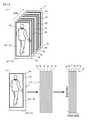
画像認識装置1(図1)は、時空間画像データ生成部2によって、動画データ4を構成するフレーム画像データ6をヒルベルトスキャンして1次元空間画像データ7を生成し、更に、1次元空間画像データ7を時間方向に配列して空間的情報と時間的情報を保持した2次元の時空間画像データ8を生成する。
このように、画像認識装置1は、空間的情報と時間的情報を保持しつつ、動画データ4を2次元の時空間画像データ8に画像変換する。
次に、画像認識装置1は、CNN部3によって、時空間画像データ8に対して2次元フィルタを用いた畳み込み処理を行い、認識対象である歩行者の行動を画像認識する。
このように、画像認識装置1は、本来は、空間2次元と時間1次元による3次元の解析を要する歩行者の行動認識を、2次元画像のCNN(深層学習を用いた人工知能の一つ)による画像認識処理によって行い、歩行者の状態を推定することができる。(1) Outline of the Embodiment In the image recognition device 1 (FIG. 1), the spatiotemporal image
In this way, the
Next, the
As described above, the
(2)実施形態の詳細
図1は、本実施の形態に係る画像認識装置1の構成を説明するための図である。
図1(a)に示した画像認識装置1は、車載装置であって、画像認識用の画像データの生成を行う時空間画像データ生成部2と深層学習を用いた人工知能による画像認識処理を行うCNN部3を備えており、車載のカメラが出力した動画データを解析して車外に存在する歩行者の有無と動作状態の分類(右直立、右歩行、左直立、左歩行など)を画像認識する。(2) Details of the Embodiment FIG. 1 is a diagram for explaining the configuration of the
The
なお、これは一例であって、例えば、車両の前方の道路や地形を読み取ったり、あるいは、監視カメラと接続して通行人を認識・追跡したりするなど、動的な認識対象を画像認識する一般的な用途に広く使用することができる。 This is just an example, and it recognizes dynamic recognition targets such as reading the road and terrain in front of the vehicle, or connecting to a surveillance camera to recognize and track passersby. It can be widely used for general purposes.
時空間画像データ生成部2は、画像データ生成装置として機能するモジュールであって、カメラが撮影・生成した動画データ4を時空間画像データ8に変換する。
カメラによって撮影された動画データ4は、時系列的に生成されたフレーム画像データ6a、6b、…から構成されている。
以降、フレーム画像データ6a、6b、…を特に区別しない場合は、単にフレーム画像データ6と記し、後述する他の構成要素についても同様とする。The spatiotemporal image
The moving
Hereinafter, when the
フレーム画像データ6は、ある瞬間において被写体(認識対象)を撮影した、空間方向の(x、y)成分を有する2次元の静止画像データである。
動画データ4は、フレーム画像データ6を撮影時間に従って時間方向(t軸とする)に時系列に順序づけて並べた静止画像データの集合であり、空間方向の2次元、時間方向の1次元を合計した3次元データとなる。
ここで、動画データ4は、空間内での認識対象の位置を時間の経過に従って記録した時系列空間情報として機能している。The
The moving
Here, the moving
時空間画像データ生成部2は、カメラから逐次送られてくるフレーム画像データ6を時系列的に所定枚数分(Q枚)を読み込む。
このように、時空間画像データ生成部2は、カメラより時系列空間情報を取得する時系列空間情報取得手段を備えている。
ここでは、一例として最初のフレーム画像データ6aから最新のフレーム画像データ6fまでの6枚のフレーム画像データ6を読み込むことにする。
なお、画像認識精度が許容範囲内に保たれる限度まで、フレーム画像データ6を所定枚数ごとに、あるいは、ランダムに読み込んだり、または、コマ落ちが生じてもよい。The spatio-temporal image
As described above, the spatiotemporal image
Here, as an example, six
It should be noted that the
なお、フレーム画像データ6を読み込む順番については、この逆も可能である。
すなわち、時空間画像データ生成部2は、カメラから逐次送られてくるフレーム画像データ6のうち、最新のものから過去のものへ時系列的に所定枚数分を読み込むようにしてもよい。この場合の一例としては、最新のフレーム画像データ6fから過去方向のフレーム画像データ6aまでの6枚のフレーム画像データ6を読み込むことになる。The order in which the
That is, the spatiotemporal image
時空間画像データ生成部2は、これらのフレーム画像データ6を読み込むと、まず、フレーム画像データ6aに対して空間方向(x軸とy軸で張られる面の面方向)にヒルベルト曲線(後述)を一筆書き的に設定する。そして、時空間画像データ生成部2は、当該ヒルベルト曲線に沿ってフレーム画像データ6aの画素の画素値をスキャン(走査)して読み取り、これらを1列に展開する。この処理は、ヒルベルトスキャンと呼ばれ、詳細は後述する。 When the spatiotemporal image
フレーム画像データ6aをヒルベルトスキャンすることにより、フレーム画像データ6aを撮影した時点での、空間的情報を含む空間方向の1次元データである1次元空間画像データ7aが得られる。
時空間画像データ生成部2は、同様にして、フレーム画像データ6b~6fも図示しない1次元空間画像データ7b~7fに変換する。
後述するように、ヒルベルト曲線は屈曲しているため、これに沿ってスキャンすると、画像の局所性を極力保持したまま2次元画像を1次元化することができる。
このように、時空間画像データ生成部2は、時系列空間情報を所定の方向(この例では、空間方向であり、時間方向とすることも可能)に走査して当該所定の方向におけるデータ値(この例では画素値)の列を取得するデータ値取得手段を備えている。
そして、当該データ値取得手段は、走査経路として、当該所定の方向におけるデータ値の局所性に対応して屈曲を繰り返す曲線(この例では、ヒルベルト曲線)を設定し、当該設定した曲線に沿って時系列空間情報を走査して当該所定の方向におけるデータ値(この例では、画素値)の列を取得している。By hill belt scanning the
Similarly, the spatiotemporal image
As will be described later, since the Hilbert curve is curved, scanning along this curve makes it possible to make a two-dimensional image one-dimensional while maintaining the locality of the image as much as possible.
As described above, the spatiotemporal image
Then, the data value acquisition means sets a curve (Hilbert curve in this example) that repeats bending corresponding to the locality of the data value in the predetermined direction as a scanning path, and follows the set curve. The time-series space information is scanned to acquire a column of data values (pixel values in this example) in the predetermined direction.
次いで、時空間画像データ生成部2は、図1(b)に示したように、1次元空間画像データ7a~7fを時間方向に(即ち撮影時間の順番に)時系列的に配列して画像認識用の時空間画像データ8を生成する。
このように、時空間画像データ生成部2は、取得したデータ値の列を、時系列空間情報の他の方向(この例では、時間方向)に対応して配列して認識対象を画像認識するための画像データ(時空間画像データ8)を生成する画像データ生成手段を備えている。Next, as shown in FIG. 1 (b), the spatiotemporal image
In this way, the spatiotemporal image
時空間画像データ8は、一辺の方向が空間的情報(空間成分)を表し、これに直交する他方の辺が時間的情報(時間成分)を表す2次元画像データである。
このように、時空間画像データ生成部2は、動画データ4を空間方向にヒルベルトスキャンして展開することにより3次元の時系列空間データである動画データ4を、空間的情報、及び時間的情報を保持しつつ、2次元の画像データである時空間画像データ8に変換する。
なお、ここでは1次元空間画像データ7の配列を時系列順としたが、画像認識が可能な範囲で順序を変更することも可能である。The
In this way, the spatiotemporal image
Although the arrangement of the one-dimensional
以上のように、時空間画像データ生成部2は、動画データの各フレーム画像データに曲線を設定し、各フレーム画像データを走査して、画素値の列をデータ値の列として取得し、更に、フレーム画像データごとの画素値の列を時間方向に対応して配列した2次元の画像データを生成している。 As described above, the spatiotemporal image
図1(a)に戻り、CNN部3は、畳み込みニューラルネットワーク(CNN:Convolutional Neural Network)を用いて2次元画像データの画像認識を行うモジュールである。
CNN部3が用いるアルゴリズムは、2次元画像データの画像認識方法として高い評価を得ており、また、広く利用されているものである。Returning to FIG. 1A, the
The algorithm used by the
本実施の形態では、CNN部3は、右直立、右歩行、左直立、左歩行、…など歩行者が取り得る各種の態様を事前学習しており、時空間画像データ生成部2が出力した時空間画像データ8を読み込んで、これから歩行者の態様が何れの分類クラスに属するかを画像認識し、その結果を出力する。
このように、時空間画像データ生成部2は、生成した画像データをCNN部3に出力する出力手段を備えている。In the present embodiment, the
As described above, the spatiotemporal image
ここで、図1(c)を用いてCNN部3の構成についてより詳細に説明する。
CNN部3は、入力側から、畳み込み層11、プーリング層12、畳み込み層13、プーリング層14、畳み込み層15、プーリング層16、全結合層17の各層を積層して構成されている。
畳み込み層11は、入力された2次元画像データ(ここでは、時空間画像データ8)に対して2次元フィルタを画像上でスライドさせてフィルタリングすることにより画像の特徴的な濃淡構造を抽出する層であり、周波数解析に対応する処理を行う。Here, the configuration of the
The
The
プーリング層12は、畳み込み層11によって抽出された特徴を保持しつつデータをダウンサンプリングして縮小する。
歩行者は、動的に動くため、フレーム画像データ6での撮影位置がずれるが、プーリング層12の処理によって歩行者を表す空間的な特徴の位置のずれを吸収することができる。これによって、空間的な位置ずれに対する画像認識精度の頑強性を高めることができる。The
Since the pedestrian moves dynamically, the shooting position in the
畳み込み層13、15と、プーリング層14、16の機能は、それぞれ、畳み込み層11、プーリング層12と同様である。
全結合層17は、一般的なニューラルネットワークであり、2次元特徴マップ(畳み込み層11~プーリング層16を経て得られるデータ)を1次元に展開し、回帰分析のような処理を行う層である。
このように、CNN部3は、画像の特徴の抽出と位置のずれの吸収を3回行った後、回帰分析的な処理を行って、歩行者の態様を画像認識する。The functions of the convolution layers 13 and 15 and the pooling layers 14 and 16 are the same as those of the
The fully connected
As described above, the
なお、畳み込み層11、13、15の2次元フィルタの値や、全結合層17のパラメータは、学習を通してチューニングされている。
学習は、分類クラスごとに多数の時空間画像データ8を用意し、これを画像認識装置1に入力して、その結果をバックプロパゲーションするなどして行う。The values of the two-dimensional filters of the convolution layers 11, 13 and 15 and the parameters of the fully connected
The learning is performed by preparing a large number of spatio-
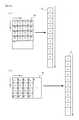
図2は、時空間画像データ生成部2が行うヒルベルトスキャンを説明するための図である。
ヒルベルトスキャンは、フレーム画像データ6に各画素を通過するヒルベルト曲線を設定し、これに沿ってスキャンすることにより、フレーム画像データ6の全体に渡って画素値を一筆書き的に読み取る処理である。FIG. 2 is a diagram for explaining a Hilbert scan performed by the spatiotemporal image
The Hilbert scan is a process of setting a Hilbert curve passing through each pixel in the
ヒルベルト曲線は、図2(a)に示したようなコの字型の曲線を組み合わせて形成される空間全体を覆う曲線であり、空間充填曲線と呼ばれるものの一種である。空間充填曲線には、この他にペアノ曲線などもある。図に示した矢線は、スキャンの方向を示している。
このように、時空間画像データ生成部2は、屈曲を繰り返す曲線として空間充填曲線を設定している。The Hilbert curve is a curve that covers the entire space formed by combining U-shaped curves as shown in FIG. 2A, and is a kind of a space-filling curve. The space-filling curve also includes the Peano curve. The arrow line shown in the figure indicates the scanning direction.
In this way, the spatiotemporal image
図2(b)に示したような、m×m(m=2)個の画素1~4が配置された画像データ20の例では、これらの画素を通過するヒルベルト曲線21を設定し、矢線の方向に画素値をスキャンして読み取った画素値を1列に並べると、画素1~画素4が順に並んだ1次元空間画像データ22が得られる。 In the example of the
図2(c)に示したような、m×m(m=4)個の画素1~Gが配置された画像データ24の例では、これらの画素を通過するヒルベルト曲線25を設定し、矢線の方向に画素値をスキャンして読み取った画素値を1列に並べると、画素1~画素Gが順に並んだ1次元空間画像データ26が得られる。
更に、より画素の多い画像データも同様に、ヒルベルト曲線に従ってスキャンする。In the example of the
Further, the image data having more pixels is similarly scanned according to the Hilbert curve.
ところで、例えば、図2(c)の画像データ24では、領域27に画素1、2、5、6が局在しているが、これらの画素は1次元空間画像データ26においても領域28に局在している。
同様に、画像データ24で局在している画素3、4、7、8も1次元空間画像データ26で局在してまとまっている。
このようにヒルベルトスキャンを用いると、画素値の局所性をできるだけ保持したまま2次元データを1次元化することができる。By the way, for example, in the
Similarly, the
By using the Hilbert scan in this way, it is possible to make two-dimensional data one-dimensional while maintaining the locality of the pixel values as much as possible.
画像認識は、画像の特徴をパターン認識するため、元画像の局所的な特徴をなるべく損なわないようにして時空間画像データ8を生成することが重要となる。
そのため、ヒルベルト曲線は、フレーム画像データ6をスキャンするための走査線として適した曲線である。
なお、これは、フレーム画像データ6をスキャンする曲線をヒルベルト曲線に限定するものではなく、ペアノ曲線などの他の空間充填曲線や、非空間充填曲線を用いることも可能である。In image recognition, since the feature of the image is recognized as a pattern, it is important to generate the
Therefore, the Hilbert curve is a curve suitable as a scanning line for scanning the
Note that this does not limit the curve for scanning the
本実施の形態では、ヒルベルト曲線を画素単位で屈曲させるが、例えば、1つおきの画素で屈曲させ、1つおきの画素値を読み取るといったように、読み取りの間隔を粗くすることも可能である。間隔が細かいほど精度は上がるが、計算コストは増大する。そのため、読み取りの間隔は、画像認識に必要とされる局所性の程度に応じて決定すればよい。
このように、時空間画像データ生成部2は、動画による3次元データをスキャンして2次元データ化することができる。このため、CNN部3は、3次元の動画データを2次元フィルタでフィルタリングすることが可能となる。これにより、動画データに3次元フィルタを適用する従来例に比して、計算コストを著しく低減することができる。In the present embodiment, the Hilbert curve is bent in pixel units, but it is also possible to bend the Hilbert curve in pixel units and read every other pixel value to make the reading interval coarser. .. The finer the interval, the higher the accuracy, but the higher the calculation cost. Therefore, the reading interval may be determined according to the degree of locality required for image recognition.
In this way, the spatiotemporal image
図3は、動画データ4をクリッピングする方法を説明するための図である。
上述したように、ヒルベルトスキャンすることによりフレーム画像データ6における画素の局所性をなるべく保持したまま時空間画像データ8を生成することができる。
しかし、局所性の全てが保存されるわけではなく、局在化していた画素が離れてしまう場合もある程度発生する。FIG. 3 is a diagram for explaining a method of clipping the moving
As described above, the space-
However, not all of the locality is preserved, and there are cases where the localized pixels are separated to some extent.
例えば、図2(c)で説明した画像データ24の例において、領域27に局在している画素1、2、5、6については、1次元空間画像データ26においても領域28に局在している。
しかし、画像データ24において局在している画素5、6、9、Aからなる領域に注目した場合、1次元空間画像データ26では画素5、6と画素9、Aとが離れてしまい、局所性が低下している。
このため、各フレーム画像データ6に対して同一条件でヒルベルトスキャンをすると、上記の画素5、6と画素9、Aとの間で生じた局所性の低下が、全てのフレーム画像データ6において生じることになり、時系列的に局所性の低下が累積されてしまう。For example, in the example of the
However, when focusing on the region consisting of
Therefore, when the Hilbert scan is performed on each
画素の局所性の低下による画像認識精度の低下を抑制する方法としては、フレーム画像データ6ごとにヒルベルト曲線の設定条件を変化させて、局所性が低下する画素をフレーム画像データ6ごとに異なるように分散することが有効である。
そこで、時空間画像データ生成部2は、次に述べるように、フレーム画像データ6ごとのヒルベルト曲線の設定条件を変化させるためにフレーム画像データ6をランダムにクリッピングする機能を備えている。As a method of suppressing the deterioration of the image recognition accuracy due to the deterioration of the locality of the pixel, the setting condition of the Hilbert curve is changed for each
Therefore, the spatiotemporal image
図3(a)に示したように、フレーム画像データ6aは、一例として64×32個の画素から構成されているとする。
これに対し、時空間画像データ生成部2は、このサイズより小さい領域をフレーム画像データ6aにランダム(任意)に設定し、フレーム画像データ6aから当該領域で形成されたクリッピング画像9aを抜き出す。クリッピング画像9aのサイズは、一例として60×30とする。As shown in FIG. 3A, it is assumed that the
On the other hand, the spatiotemporal image
画像にヒルベルト曲線を設定する場合、一辺のサイズが2のn乗(nは自然数)であることが必要である。
そこで、時空間画像データ生成部2は、図3(b)に示したように、クリッピング画像9aの周囲に適当な画素を追加するパディングという処理を行って、64×32のフレーム画像データ6aを復元する
そして、時空間画像データ生成部2は、復元したフレーム画像データ6aにヒルベルト曲線を設定してスキャンし、追加した画素の画素値はメモリに読み込まずにスキップして1次元空間画像データ7aを生成する。When setting a Hilbert curve in an image, it is necessary that the size of one side is 2 to the nth root (n is a natural number).
Therefore, as shown in FIG. 3B, the spatiotemporal image
時空間画像データ生成部2は、同様に、フレーム画像データ6b~6fを任意の範囲でクリッピングしてクリッピング画像9b~9fを生成し、これらをパディングしてからヒルベルトスキャンして1次元空間画像データ7b~7fを生成する。
そして、時空間画像データ生成部2は、1次元空間画像データ7a~7fを時系列順に配設して時空間画像データ8を生成する。
以上の例では、クリッピング画像9aをフレーム画像データ6ごとに任意の領域に設定したが、何らかの規則性に従って設定してもよい。Similarly, the spatiotemporal image
Then, the spatiotemporal image
In the above example, the
クリッピング後に復元したフレーム画像データ6にヒルベルト曲線を設定することにより、ヒルベルト曲線の開始点や画素を通過する経路がフレーム画像データ6ごとに変化し、画素の非局在化を様々な画素に分散することができる。
このように、時空間画像データ生成部2は、フレーム画像データごとに、曲線の設定範囲を変化させることにより曲線の設定条件を変化させる。By setting the Hilbert curve in the
In this way, the spatio-temporal image
このような、学習画像やフレーム画像データ6から一回り小さい画像をランダムで切り出して、空間的情報の保持を網羅的にする処理は、データオーギュメンテーションと呼ばれている。
データオーギュメンテーションは、事前学習用の動画データと動画データ4の双方について行われる。Such a process of randomly cutting out a smaller image from the training image or the
Data augmentation is performed on both the video data for pre-learning and the
図4は、クリッピングの変形例を説明するための図である。
この変形例では、時空間画像データ生成部2は、クリッピング画像9aの上半分から30×30のクリッピング画像を抜き出した後、パディングして32×32のフレーム画像データ31aを生成する。
同様にして、時空間画像データ生成部2は、クリッピング画像9b~9fから図示しないフレーム画像データ31b~31fを生成する。FIG. 4 is a diagram for explaining a modification of clipping.
In this modification, the spatio-temporal image
Similarly, the spatiotemporal image
そして、時空間画像データ生成部2は、ヒルベルトスキャンによってフレーム画像データ31a~31fから1次元空間画像データ7a~7fを生成し、これらを時系列順に配設して時空間画像データ8を生成する。
クリッピング画像9を半分にリサイズすることにより、1次元空間画像データ7や時空間画像データ8のデータ量も半分になり、より小型の画像認識装置1での処理が可能となる。Then, the spatiotemporal image
By resizing the
この例では、クリッピング画像9の上半分を再度クリッピングしたが、下半分や中間部分をクリッピングしてもよい。
また、フレーム画像データ6を直接クリッピングしてクリッピング画像を生成してもよい。In this example, the upper half of the
Further, the
図5は、画像認識装置1のハードウェア的な構成の一例を示した図である。
画像認識装置1は、車載用に構成されているが、航空機や船舶などの他の形態の移動体に搭載したり、あるいは、スマートフォンなどの携帯端末に搭載したり、更には、パーソナルコンピュータなどの据え置き型の装置に搭載したりすることができる。FIG. 5 is a diagram showing an example of a hardware-like configuration of the
Although the
画像認識装置1は、CPU41、ROM42、RAM43、記憶装置44、カメラ45、入力部46、及び出力部47などがバスラインで接続されて構成されている。
CPU41は、中央処理装置であって、記憶装置44が記憶する画像認識プログラムに従って動作し、上述した歩行者の画像認識を行う。The
The
ROM42は、読み出し専用のメモリであって、CPU41を動作させるための基本的なプログラムやパラメータを記憶している。
RAM43は、読み書きが可能なメモリであって、CPU41が動画データ4から時空間画像データ8を生成したり、更に、時空間画像データ8から歩行者を画像認識する際のワーキングメモリを提供する。The
The
記憶装置44は、ハードディスクなどの大容量の記憶媒体を用いて構成されており、画像認識プログラムを記憶している。
画像認識プログラムは、CPU41に時空間画像データ生成部2やCNN部3としての機能を発揮させるプログラムである。The
The image recognition program is a program that causes the
カメラ45は、車外を動画撮影する車載カメラであって、所定のフレームレートでフレーム画像データ6を出力する。
入力部46は、画像認識装置1を操作するための操作ボタンなどから構成され、出力部47は、画像認識装置1の設定画面などを表示するディスプレイなどから構成されている。
本実施の形態では、画像認識装置1を車載装置とするが、カメラ45を車両に設置し、ネットワーク通信によって動画をサーバに送信し、サーバで画像認識して認識結果を車両に送信するように構成することもできる。The
The
In the present embodiment, the
図6は、画像認識装置1が行う画像認識処理の手順を説明するためのフローチャートである。
以下の処理は、CPU41が画像認識プログラムに従って行うものである。また、CPU41の処理に対応する機能部を括弧にて示す。
まず、カメラ45が車外を撮影して動画データ4を逐次的に出力している。
次に、CPU41(時空間画像データ生成部2)は、動画フレームをQ枚読み込む(ステップ5)。すなわち、CPU41は、出力される動画データ4における所定枚数Q枚(例えば、6枚)のフレーム画像データ6を出力順にRAM43に読み込む。FIG. 6 is a flowchart for explaining the procedure of the image recognition process performed by the
The following processing is performed by the
First, the
Next, the CPU 41 (spatio-temporal image data generation unit 2) reads Q moving image frames (step 5). That is, the
次に、CPU41(時空間画像データ生成部2)は、パラメータiを0にセットしてRAM43に記憶する(ステップ10)。
そして、CPU41(時空間画像データ生成部2)は、RAM43からi番目のフレーム画像データ6を読み出し、これからクリッピング画像9を生成してRAM43に記憶する(ステップ15)。フレーム画像データ6からクリッピング画像9を生成する領域は、乱数を発生させて、これに基づいてランダムに決定する。
なお、i=0番目のフレーム画像データ6は、Q枚のうちの1枚目に対応する。即ち、i番目のフレーム画像データ6は、Q枚の内のi+1枚目に対応する。Next, the CPU 41 (space-time image data generation unit 2) sets the parameter i to 0 and stores it in the RAM 43 (step 10).
Then, the CPU 41 (spatio-temporal image data generation unit 2) reads the i-th
The i = 0th
次に、CPU41(時空間画像データ生成部2)は、クリッピング画像9をパディングしてフレーム画像データ6を復元し、これをRAM43に記憶する。
そして、CPU41(時空間画像データ生成部2)は、RAM43に記憶した当該フレーム画像データ6にヒルベルト曲線を設定してヒルベルトスキャンを行い(ステップ20)、1次元空間画像データ7を生成する(ステップ25)。Next, the CPU 41 (spatio-temporal image data generation unit 2) pads the
Then, the CPU 41 (spatio-temporal image data generation unit 2) sets a Hilbert curve in the
次に、CPU41(時空間画像データ生成部2)は、生成した1次元空間画像データ7をRAM43に記憶して時空間画像データ8を生成する(ステップ30)。
なお、i=0の場合は、まず、最初の1次元空間画像データ7aをRAM43に記憶し、i=1、2、…の場合には、既にRAM43に記憶してある1次元空間画像データ7に時系列的に追加していく。Next, the CPU 41 (spatio-temporal image data generation unit 2) stores the generated one-dimensional
When i = 0, the first one-dimensional
次に、CPU41(時空間画像データ生成部2)は、RAM43に記憶してあるiに1をインクリメントした後(ステップ35)、iがQ未満か否かを判断する(ステップ40)。
iがQ未満の場合(ステップ40;Y)、CPU41(時空間画像データ生成部2)は、ステップ15に戻り、次のフレーム画像データ6に対して同様の処理を行う。Next, the CPU 41 (spatio-temporal image data generation unit 2)
When i is less than Q (step 40; Y), the CPU 41 (space-time image data generation unit 2) returns to step 15 and performs the same processing on the next
一方、iがQ未満でない場合(ステップ40;N)、RAM43に時空間画像データ8が完成したため、CPU41(CNN部3)は、RAM43から時空間画像データ8を読み出し、これを画像認識する(ステップ45)。
そして、CPU41(CNN部3)は、画像認識結果を所定の出力先に出力する(ステップ50)。
出力先は、例えば、車両の制御系であり、車両前方に歩行者が存在する場合に車速の制動を行ったりする。On the other hand, when i is not less than Q (step 40; N), the space-
Then, the CPU 41 (CNN unit 3) outputs the image recognition result to a predetermined output destination (step 50).
The output destination is, for example, a vehicle control system, and brakes the vehicle speed when a pedestrian is present in front of the vehicle.
次に、CPU41(CNN部3)は、画像認識処理を終了するか否かを判断する(ステップ55)。
処理を終了しない場合(ステップ55;N)、CPU41(CNN部3)は、ステップ5に戻る。一方、ユーザが終了ボタンを選択するなどして処理を終了する場合(ステップ55;Y)、CPU41(CNN部3)は、処理を終了する。Next, the CPU 41 (CNN unit 3) determines whether or not to end the image recognition process (step 55).
If the process is not completed (
図7は、実験結果を説明するための図である。
この図は、画像認識装置1の画像認識能力を10分割交差検定という評価方法により評価した結果を表した表である。
10分割交差検定とは、1つのデータセット(例えば時空間画像データ8の1万セット分)を10個(1000セット)に分割した後、9個で学習し、残りの1つで正答率を評価する、という処理を繰り替えし行う評価方法である。FIG. 7 is a diagram for explaining the experimental results.
This figure is a table showing the results of evaluating the image recognition ability of the
The 10-fold cross-validation test divides one data set (for example, 10,000 sets of spatiotemporal image data 8) into 10 pieces (1000 sets), learns with 9 pieces, and determines the correct answer rate with the remaining one. This is an evaluation method in which the process of evaluating is repeated.
この表の上段は、画像認識装置1を用いた場合を示しており、下段はLSTM(Long Short Term Memory)と呼ばれる従来技術(従来技術の項目で説明したものとは異なる)を用いた場合を示している。
評価項目は、正答率であり、画像認識装置1の場合は77.1%、LSTMの場合は74.0%となっている。
このように、画像認識装置1の正答率は、LSTMを上回っており、画像認識装置1は、従来技術と比較して高い画像認識能力を備えていることが分かる。The upper part of this table shows the case where the
The evaluation item is the correct answer rate, which is 77.1% in the case of the
As described above, the correct answer rate of the
(変形例1)
実施の形態では、クリッピングにより離散化する画素を分散させたが、本変形例では、ヒルベルト
スキャンの経路、即ち、ヒルベルト曲線の形態をフレーム画像データ6ごとに変化させることにより離散化する画素の分散を行う。
ヒルベルト曲線の始点から最初の一歩目を右側に進む場合を形態1とし、下側に進む場合を形態2とし、上側に進む場合を形態3とし、左側に進む場合を形態4とする。はじめの一歩目の位置がフレーム画像データ6の外となる場合は、パディングして当該パディング部分に関しては、スキャン時に画素値の読み込みを行わないものとする。(Modification 1)
In the embodiment, the pixels discretized by clipping are dispersed, but in this modification, the path of the Hilbert scan, that is, the dispersion of the pixels discretized by changing the morphology of the Hilbert curve for each
このようにヒルベルト曲線の形態を複数用意し、これらをフレーム画像データ6に適当に割り当てることにより、空間的情報と時間的情報の保持を網羅的にする。
割り当て方は各種考えられ、例えば、フレーム画像データ6aは、形態1のヒルベルト曲線でヒルベルトスキャンし、フレーム画像データ6bは、形態2のヒルベルト曲線でヒルベルトスキャンし、…といったように、形態1から形態4までを順番に割り当ててもよいし、あるいは、形態1~形態4から任意に選んだ形態をフレーム画像データ6aに割り当て、残りの形態から任意に選んだ形態をフレーム画像データ6bに割り当て、…といったように、形態を任意に割り当ててもよい。By preparing a plurality of Hilbert curve forms in this way and appropriately allocating them to the
Various allocation methods can be considered. For example, the
また、例えば、フレーム画像データ6aは、ヒルベルト曲線、フレーム画像データ6bは、ペアノ曲線、フレーム画像データ6cは、ヒルベルト曲線、フレーム画像データ6dは、ペアノ曲線、…といったように、種類の異なる空間充填曲線により曲線の形態を変えてもよい。
更に、フレーム画像データ6aは、形態1のヒルベルト曲線、フレーム画像データ6bは、形態1のペアノ曲線、フレーム画像データ6cは、形態2のヒルベルト曲線、フレーム画像データ6dは、形態2のペアノ曲線、…といったように、曲線の種類と曲線の形態の両方を変えてもよい。
このように、この例の時空間画像データ生成部2は、曲線の設定条件として、フレーム画像データごとに、曲線の設定形態を変化させている。Further, for example, the
Further, the
As described above, the spatio-temporal image
(変形例2)
変形例1では、フレーム画像データ6ごとにヒルベルト曲線の形態を変化させてヒルベルトスキャンしたが、本変形例では、1つのフレーム画像データ6に対して形態の異なる複数のヒルベルト曲線を設定する。
例えば、フレーム画像データ6aを形態1のヒルベルト曲線でスキャンして1次元空間画像データ7a1を生成し、更に、フレーム画像データ6aを形態2のヒルベルト曲線でスキャンして1次元空間画像データ7a2を生成し、…、次に、フレーム画像データ6bを形態1のヒルベルト曲線でスキャンして1次元空間画像データ7b1を生成し、更に、フレーム画像データ6bを形態2のヒルベルト曲線でスキャンして1次元空間画像データ7b2を生成し、…、といったように、フレーム画像データ6fまで、各フレーム画像データ6を形態の異なるヒルベルト曲線で複数回スキャンした後、1次元空間画像データ7a1、7a2、…、7b1、7b2、…、を配列して時空間画像データ8を生成する。(Modification 2)
In the first modification, the form of the Hilbert curve is changed for each
For example, the
あるいは、1次元空間画像データ7a1、7b1、…から時空間画像データ8aを生成し、1次元空間画像データ7a2、7b2、…から時空間画像データ8bを生成し、といったように、複数の時空間画像データ8a、8b、…を生成し、これらを個別に画像認識して、その結果を総合して判断してもよい。
また、同一のフレーム画像データ6aを任意に複数回クリッピングし、これらをそれぞれパディングした後にヒルベルトスキャンすることにより、複数の1次元空間画像データ7a1、7a2、…を生成することもできる。同様にフレーム画像データ6bから1次元空間画像データ7b1、7b2、…を生成する。
このように、フレーム画像データ6を複数回任意にクリッピングすることにより同一のフレーム画像データ6から複数の1次元空間画像データ7を生成することもできる。
以上に説明したように、変形例2の画像認識装置1は、同一のフレーム画像データに対して曲線の設定条件を変化させて、当該設定条件ごとにデータ値を取得している。Alternatively, a plurality of spatiotemporal image data 8a are generated from the one-dimensional spatial image data 7a1, 7b1, ..., And a spatiotemporal image data 8b is generated from the one-dimensional spatial image data 7a2, 7b2, .... Image data 8a, 8b, ... may be generated, these may be individually image-recognized, and the results may be comprehensively determined.
Further, it is also possible to generate a plurality of one-dimensional spatial image data 7a1, 7a2, ... By clipping the same
In this way, it is possible to generate a plurality of one-dimensional
As described above, the
(変形例3)
本変形例では、1つのフレーム画像データ6に複数回ランダムにクリッピング画像9の領域を設定し、1つのフレーム画像データ6から複数枚のクリッピング画像9を生成する。
例えば、フレーム画像データ6aから領域1のクリッピング画像9a1を生成し、同じくフレーム画像データ6aから領域2のクリッピング画像9a2を生成し、…、次に、フレーム画像データ6bから領域1のクリッピング画像9b1を生成し、同じくフレーム画像データ6bから領域2のクリッピング画像9b2を生成し、…、といったように、フレーム画像データ6fまで、各フレーム画像データ6から切り抜き領域の異なるクリッピング画像9を複数個生成する。(Modification 3)
In this modification, the area of the
For example, the clipping image 9a1 of the
そして、時空間画像データ生成部2は、これらのクリッピング画像9のそれぞれをパディングしてフレーム画像データ6を復元する。
これにより、元画像のフレーム画像データ6aから複数枚のフレーム画像データ6a1、6a2、…が復元される。フレーム画像データ6b、6c、…も同様である。Then, the spatiotemporal image
As a result, a plurality of frame image data 6a1, 6a2, ... Are restored from the
時空間画像データ生成部2は、これらフレーム画像データ6a1、6a2、…、6b1、6b2、…をヒルベルトスキャンして1次元空間画像データ7を生成し、これらを時系列的に配列して時空間画像データ8を生成する。
あるいは、フレーム画像データ6a1、6b1、…から時空間画像データ8aを生成して画像認識し、フレーム画像データ6a2、6b2、…から時空間画像データ8bを生成して画像認識し、これらの画像認識の結果を総合して判断してもよい。The spatiotemporal image
Alternatively, spatiotemporal image data 8a is generated from the frame image data 6a1, 6b1, ..., And image recognition is performed, spatiotemporal image data 8b is generated from the frame image data 6a2, 6b2, ..., And image recognition is performed, and these image recognitions are performed. The results of the above may be comprehensively judged.
(変形例4)
変形例2と変形例3を組み合わせる。即ち、変形例3で生成したフレーム画像データ6a1、6a2、…、6b1、6b2、…を複数種類の形態の曲線でスキャンする。
例えば、フレーム画像データ6a1は、形態1のヒルベルト曲線でスキャンし、フレーム画像データ6a2は、形態1のペアノ曲線でスキャンし、…、といったようにスキャンする。(Modification example 4)
The
For example, the frame image data 6a1 is scanned by the Hilbert curve of the
(変形例5)
実施の形態では、空間2次元、時間1次元の(x、y、t)成分を持つ3次元の動画データ4を空間方向(x、y方向)にヒルベルトスキャンして(α、t1)、(α、t2)、…の1次元空間画像データ7a、7b、…を生成し、これをt1、t2、…の時間方向の順に配列して(α、t)成分を持つ2次元の時空間画像データ8を生成した。ここで、αは、画素の位置をヒルベルト曲線に沿った長さで表した座標値である。(Modification 5)
In the embodiment, the three-dimensional moving
本変形例では、時間座標(t軸)の方向にヒルベルトスキャンする。
例えば、(y、t)方向にヒルベルトスキャンして(x1、α)、(x2、α)、…の1次元空間画像データ7a、7b、…を生成し、これをx1、x2、…の順に配列して(x、α)成分を持つ2次元の時空間画像データ8を生成することが可能である。同様に(x、t)方向にヒルベルトスキャンして(y、α)成分を持つ時空間画像データ8を生成することも可能である。In this modification, the Hilbert scan is performed in the direction of the time coordinates (t-axis).
For example, one-dimensional
また、同一の動画データ4に対して、(α、t)、(x、α)、(y、α)の各成分を持つ3種類の時空間画像データ8を生成し、これらを組み合わせて画像認識処理することも可能である。
例えば、(α、t)成分の時空間画像データ8を画像認識し、(x、α)成分の時空間画像データ8を画像認識し、(y、α)成分の時空間画像データ8を画像認識し、それぞれの結果を全結合層17の出力値で重み付けして加重平均を取ったり、あるいは、(α、t)、(x、α)、(y、α)のそれぞれから生成される3つの時空間画像データ8を配列して1つの時空間画像データ8とし、当該時空間画像データ8を画像認識することが可能である。
時間方向にスキャンすることにより、動画のフレームレートを低減できることが期待される。これにより画像処理の負荷が低減される。Further, three types of
For example, the spatio-
It is expected that the frame rate of moving images can be reduced by scanning in the time direction. This reduces the load of image processing.
(変形例6)
本変形例では、更に高次の時系列空間情報を画像認識する。
近年、車両前方の地形をライダー(LiDAR)と呼ばれるレーザーレーダーを用いた技術によって地形を読み取り、車両を自動運転する技術が研究されている。
ライダーで得られる時系列空間情報は、空間3次元と時間1次元の(x、y、z、t)成分を有する4次元データである。(Modification 6)
In this modification, higher-order time-series space information is image-recognized.
In recent years, research has been conducted on a technique for automatically driving a vehicle by reading the terrain in front of the vehicle by a technique using a laser radar called a lidar (LiDAR).
The time-series spatial information obtained by the rider is four-dimensional data having three-dimensional space and one-dimensional time (x, y, z, t) components.
この時系列空間情報を空間3次元的な(x、y、z)方向で屈曲するヒルベルト曲線でスキャンすると、(α、t1)、(α、t2)、…といった1次元空間画像データ7が得られる。これをt1、t2、…の時系列順に配列すると2次元の(α、t)成分を有する時空間画像データ8が得られる。これを画像認識することにより、歩行者や地形などを検出することが可能となる。変形例5と同様に時間方向にスキャンすることも可能である。 When this time-series spatial information is scanned with a Hilbert curve that bends in the spatial three-dimensional (x, y, z) direction, one-dimensional
また、4次元の時系列空間情報をz方向、t方向に固定して(x、y)方向にヒルベルトスキャンすることにより(α、z1、t1)、(α、z2、t1)、(α、z3、t1)、…、(α、z1、t2)、(α、z2、t2)、(α、z3、t2)、…からなる1次元空間画像データ7が得られる。
これをt1を固定してz方向に配列して(α、z、t1)、(α、z、t2)、…の2次元空間画像データが得られる。
更に、これらを時系列的に配列すると(α、z、t)の3次元時空間画像データが得られる。
画像認識装置1の畳み込み用のフィルタとして3次元フィルタを設定し、上記3次元時空間画像データを画像認識することが可能である。
また、変形例5と同様に時間方向にヒルベルトスキャンすることも可能である。Further, by fixing the four-dimensional time-series space information in the z direction and the t direction and performing a hill belt scan in the (x, y) direction, (α, z1, t1), (α, z2, t1), (α, One-dimensional
Two-dimensional spatial image data of (α, z, t1), (α, z, t2), ... Are obtained by fixing t1 and arranging them in the z direction.
Further, by arranging these in chronological order, (α, z, t) three-dimensional spatiotemporal image data can be obtained.
It is possible to set a three-dimensional filter as a convolution filter of the
Further, it is also possible to perform a hill belt scan in the time direction as in the modified example 5.
このように、n次元(nは、2以上の整数)をヒルベルトスキャンによってn-1次元以下の時空間画像データに変換することが可能である。
そのため、色情報や各種センサ値など、更に情報を付加して高次元の時系列空間情報を生成し、これを低次元化して画像認識装置1で画像認識することが可能である。In this way, it is possible to convert n dimensions (n is an integer of 2 or more) into spatiotemporal image data of n-1 dimension or less by Hilbert scanning.
Therefore, it is possible to generate high-dimensional time-series space information by further adding information such as color information and various sensor values, reduce the dimension, and recognize the image by the
(変形例7)
図8は、変形例7を説明するための図である。本変形例では、ラスタスキャンにて画像データを走査する。
時空間画像データ生成部2は、図8(a)に示したフレーム画像データ6のアスペクト比を検出し、短手方向を走査方向(スキャン方向)に決定する。これは、後述の実験結果で述べるように、長手方向を走査方向とする場合よりも、短手方向を走査方向とした場合の方が認識率が高かったためである。
そして、時空間画像データ生成部2は、短手方向の直線状の走査経路に沿って走査することにより、フレーム画像データ6の全体をラスタスキャンする。(Modification 7)
FIG. 8 is a diagram for explaining a
The spatiotemporal image
Then, the spatiotemporal image
なお、この例では、フレーム画像データ6の全体を走査するが、フレーム画像データ6をクリッピングした画像データや、フレーム画像データ6から興味領域として抽出した画像データ、更には、当該抽出した画像データをクリッピングした画像データを対象とすることもできる。
このように、時空間画像データ生成部2は、直線状の走査経路に沿ってデータ値の列を取得するデータ値取得手段として機能しており、動画データを構成するフレーム画像の少なくとも一部の画像データに対して走査経路の走査方向を決定する走査方向決定手段を備えている。
更に、当該走査方向決定手段は、画像データによって形成される画像の短手方向に走査方向を決定している。In this example, the entire
As described above, the spatiotemporal image
Further, the scanning direction determining means determines the scanning direction in the lateral direction of the image formed by the image data.
図8(a)のフレーム画像データ6aの場合、x軸方向が短手方向、y軸が長手方向であるため、時空間画像データ生成部2は、x軸方向を走査方向に決定する。
そして、時空間画像データ生成部2は、図に示した実線の矢線に沿って、第1行目の画素1から画素4までx軸方向に順に画素値を読み取っていく。時空間画像データ生成部2は、走査が端部の画素4に達すると、破線の矢線に示したように、第2行目の先頭の画素5に走査開始位置を移動し、x軸方向に端部の画素8まで画素値を順に読み取っていく。In the case of the
Then, the spatiotemporal image
以下、時空間画像データ生成部2は、同様の動作を繰り返してフレーム画像データ6aの全ての画素値を読みとり、これを一列に並べて、1次元空間画像データ7aを生成する。更に、時空間画像データ生成部2は、同様にして1次元空間画像データ7b、7c、・・・も生成する。
そして、時空間画像データ生成部2は、生成した1次元空間画像データ7a、7b、・・・から時空間画像データ8を生成する。これをCNN部3で画像認識する手順は、上述の実施形態と同様である。Hereinafter, the spatiotemporal image
Then, the spatiotemporal image
以上のラスタスキャン方法は、一例であって、例えば、実線の矢線方向とは逆の、画素4から画素1の方向に走査してもよいし、画素1から画素4まで順に第1行目の画素を読み終わると、第2行目に関しては、画素8から画素5の方向に読み取るというように、蛇行した直線経路でラスタスキャンすることもできる。 The above raster scan method is an example, and may be scanned in the direction from
短手方向、及び長手方向にラスタスキャンして画素を展開する1次元変換を用いた場合と、ヒルベルトスキャンによる1次元変換を用いた場合を10分割交差検定で正答率を算出する実験を行ったところ、短手方向にラスタスキャンした場合は、82.2%、長手方向にラスタスキャンした場合は、77.7%、ヒルベルトスキャンした場合は、83.6%となった。 An experiment was conducted to calculate the correct answer rate by a 10-division cross test when using a one-dimensional conversion that expands pixels by raster scanning in the lateral and longitudinal directions and when using a one-dimensional conversion by Hilbert scan. However, it was 82.2% in the case of raster scan in the lateral direction, 77.7% in the case of raster scan in the longitudinal direction, and 83.6% in the case of hill belt scan.
このように、短手方向のラスタスキャンは、長手方向のラスタスキャンより正答率が高くなり、ヒルベルトスキャンに近い値を実現することができた。
これは、短手方向のラスタスキャンは、長手方向のラスタスキャンに比べて、画像データの端点で次の行の画素行に移動する際の移動距離が小さいため、画像の局所性の保存状態が長手方向にラスタスキャンする場合よりもよいためではないかと思われる。As described above, the raster scan in the short direction has a higher correct answer rate than the raster scan in the longitudinal direction, and a value close to that of the Hilbert scan can be realized.
This is because the raster scan in the short direction has a smaller movement distance when moving to the pixel row of the next row at the end point of the image data than the raster scan in the longitudinal direction, so that the locality of the image is preserved. This may be because it is better than the case of raster scan in the longitudinal direction.
図8(b)は、y軸方向が短手方向となる場合を示している。
この場合、時空間画像データ生成部2は、実線の矢線で示したように、画素1から画素Dまで、短手方向、即ち、y方向に画素値を順に読み取っていき、端部の画素Dに達すると、破線の矢線で示したように次の列の先頭画素2に移動して、画素Eまで画素値を読み取っていく。
以下、時空間画像データ生成部2は、同様の動作を繰り返してフレーム画像データ6aの全ての画素値を読みとり、これを一列に並べて、1次元空間画像データ7aを生成する。FIG. 8B shows a case where the y-axis direction is the lateral direction.
In this case, the spatiotemporal image
Hereinafter, the spatiotemporal image
以上の例では、時空間画像データ生成部2は、フレーム画像データ6のアスペクト比を判断して短手方向を走査方向に決定したが、画像データの短手方向が予め決まっている場合は、その方向を走査方向に設定しておき、アスペクト比の判断処理を省くことも可能である。 In the above example, the spatiotemporal image
図9は、変形例7の画像認識処理の手順を説明するためのフローチャートである。
上述した実施形態と同じ処理には同じステップ番号を付し、説明を省略する。
この例では、フレーム画像データ6をクリッピングすることによりデータオーギュメンテーションを行っている。
時空間画像データ生成部2は、ステップ15にて、i番目のフレーム画像データをクリッピングすると、クリッピング後のフレーム画像データ6の短手方向を走査方向(スキャン方向)に決定する(ステップ80)。
そして、時空間画像データ生成部2は、決定した走査方向にクリッピング後のフレーム画像データ6をラスタスキャンして(ステップ85)、1次元空間画像データ7を生成する(ステップ25)。他は、上述の実施形態と同様である。FIG. 9 is a flowchart for explaining the procedure of the image recognition process of the
The same process as that of the above-described embodiment is assigned the same step number, and the description thereof will be omitted.
In this example, data augmentation is performed by clipping the
When the i-th frame image data is clipped in
Then, the spatiotemporal image
以上では、短手方向にラスタスキャンしたが、例えば、ハードウェア的な要因などから長手方向にラスタスキャンした方が好ましい場合など(精度は低下しても処理速度が速くなるなど)ユーザの事情に応じて長手方向にラスタスキャンしてもよい。 In the above, the raster scan is performed in the short direction, but for example, when it is preferable to perform the raster scan in the longitudinal direction due to hardware factors (for example, the processing speed becomes faster even if the accuracy decreases), it depends on the user's circumstances. Raster scan may be performed in the longitudinal direction accordingly.
(変形例8)
図10は、変形例8を説明するための図である。
本変形例の時空間画像データ生成部2は、フレーム画像データ6を小領域51に分割し、分割した小領域51ごとにラスタスキャンする。
図10(a)の例では、時空間画像データ生成部2は、フレーム画像データ6を太線で示した正方形の小領域51a1、51a2、・・・に分割する。小領域51内の升目は画素を表している。(Modification 8)
FIG. 10 is a diagram for explaining the modified example 8.
The spatio-temporal image
In the example of FIG. 10A, the spatiotemporal image
時空間画像データ生成部2は、小領域51a1をラスタスキャンして1次元空間画像データ7a1(図示せず)を生成し、次いで小領域51a2をラスタスキャンして1次元空間画像データ7a2を作成し、・・・というように、各小領域51をラスタスキャンする。スキャンの走査方向は、例えば、フレーム画像データ6aの短手方向とする。
そして、時空間画像データ生成部2は、1次元空間画像データ7a1、7a2、・・・を一列に連結してフレーム画像データ6aの1次元空間画像データ7a(図示せず)を生成する。
時空間画像データ生成部2は、同様にして、1次元空間画像データ7b、7c・・・を生成し、これらを時間方向に配列して時空間画像データ8(図示せず)を生成する。The spatiotemporal image
Then, the spatiotemporal image
Similarly, the spatiotemporal image
1次元空間画像データ7a1、7a2、・・・を連結する順序は、各種のものが可能であり、例えば、小領域51a1、小領域51a2、・・・をフレーム画像データ6aの短手方向にラスタスキャンする順序であってもよいし、あるいは、小領域51a1、小領域51a2、・・・を結ぶヒルベルト曲線を設定し、当該ヒルベルト曲線で結ばれる順序であってもよい。後者の場合は、ラスタスキャンとヒルベルトスキャンを組み合わせることができる。あるいは、小領域51a1、51a2、・・・内でヒルベルトスキャンして、その結果得られた1次元空間画像データ7a1、7a2、・・・を小領域51a1、51a2、・・・をラスタスキャンする順序で連結することによりラスタスキャンとヒルベルトスキャンを組み合わせることもできる。 The order of connecting the one-dimensional spatial image data 7a1, 7a2, ... Can be various. For example, the small area 51a1, the small area 51a2, ... Are rasterized in the lateral direction of the
図10(b)は、y軸方向が短手方向となるフレーム画像データ6aに対して、x軸方向が短手方向となる小領域51a1、51a2、・・・を設定した例である。
この場合は、小領域51a1、小領域51a2、・・・に関しては、例えば、これら小領域51の短手方向を優先してx軸方向にラスタスキャンするように構成することができる。
小領域51a1、小領域51a2、・・・から生成される1次元空間画像データ7a1、7a2、・・・(図示せず)に関しては、図10(a)の場合と同様に適当な所定の順序で連結する。FIG. 10B is an example in which small regions 51a1, 51a2, ...
In this case, the small areas 51a1, the small areas 51a2, ..., For example, can be configured to give priority to the lateral direction of these small areas 51 and perform raster scan in the x-axis direction.
Regarding the one-dimensional spatial image data 7a1, 7a2, ... (Not shown) generated from the small area 51a1, the small area 51a2, ... Connect with.
以上に説明した実施形態、及び変形例によって次のような効果を得ることができる。
(1)動画データを2次元の画像データで表現することができる。
(2)空間充填曲線を用いたヒルベルトスキャンや、ラスタスキャンを用いてフレーム画像データ6を画像変換することにより、空間的情報と時間的情報を保持したまま動画データ4(時系列画像データ)から2次元の時空間画像データ8を生成することができる。
(3)時空間画像データ8を入力データとすることにより、2次元フィルタを用いたCNNで動画データを画像認識することができる。
(4)時空間画像データ8において隣接する画素間の情報に関係性を持たせることができるので画像認識精度の向上が見込める。
(5)一般的な2次元フィルタを用いたCNNを用いることができるため、CNNの導入に要するコストやCNNの実行に要する計算コストを低減することができる上、認識精度の向上も見込める。
(6)一般に、車載カメラや車載コンピュータには、高価なハードウェアが搭載されないため、使用メモリが少なく計算コストが低い画像認識装置1が実装に適している。
(7)データオーギュメンテーションなど、スキャンする曲線の設定条件を変化させることにより、時空間画像データ8の空間的情報の保持を網羅的にすることができる。
(8)事前学習フェーズや画像認識フェーズなどにおいて、一回り小さい画像をランダムで切り出すデータオーギュメンテーションを行うことにより空間情報と時間情報の保持を網羅的にすることができる。The following effects can be obtained by the embodiments and modifications described above.
(1) The moving image data can be expressed by two-dimensional image data.
(2) By converting the
(3) By using the
(4) Since the information between adjacent pixels in the
(5) Since a CNN using a general two-dimensional filter can be used, it is possible to reduce the cost required for introducing the CNN and the calculation cost required for executing the CNN, and it is expected that the recognition accuracy will be improved.
(6) Generally, since an in-vehicle camera or an in-vehicle computer is not equipped with expensive hardware, the
(7) By changing the setting conditions of the curve to be scanned, such as data augmentation, it is possible to comprehensively retain the spatial information of the
(8) In the pre-learning phase, the image recognition phase, and the like, it is possible to comprehensively retain spatial information and temporal information by performing data augmentation that randomly cuts out a slightly smaller image.
1 画像認識装置
2 時空間画像データ生成部
3 CNN部
4 動画データ
6、31 フレーム画像データ
7 1次元空間画像データ
8 時空間画像データ
9、 クリッピング画像
11、13、15 畳み込み層
12、14、16 プーリング層
17 全結合層
20、24 画像データ
21、25 ヒルベルト曲線
22、26 1次元空間画像データ
27、28 領域
41 CPU
42 ROM
43 RAM
44 記憶装置
45 カメラ
46 入力部
47 出力部
51 小領域1
42 ROM
43 RAM
44
Claims (14)
Translated fromJapanese前記取得した時系列空間情報を所定の方向に走査して当該所定の方向におけるデータ値の列を取得するデータ値取得手段と、
前記取得したデータ値の列を、前記時系列空間情報の他の方向に対応して配列して前記認識対象を画像認識するための画像データを生成する画像データ生成手段と、
前記生成した画像データを出力する出力手段と、
を具備し、
前記データ値取得手段は、前記所定の方向におけるデータ値の局所性に対応して屈曲を繰り返す空間充填曲線を走査経路として設定し、当該設定した走査経路に沿って前記データ値の列を取得する、
ことを特徴とする画像データ生成装置。A time-series space information acquisition means for acquiring time-series space information in which the position of a recognition target in space is recorded over time, and
A data value acquisition means that scans the acquired time-series space information in a predetermined direction and acquires a column of data values in the predetermined direction.
An image data generation means for arranging a sequence of acquired data values corresponding to other directions of the time-series spatial information to generate image data for image recognition of the recognition target.
An output means for outputting the generated image data and
Equippedwith
The data value acquisition means sets a space-filling curve that repeats bending corresponding to the locality of the data value in the predetermined direction as a scanning path, and acquires a sequence of the data values along the set scanning path. ,
An image data generator characterized by this.
前記データ値取得手段は、前記動画データの各フレーム画像データに前記曲線を設定し、前記各フレーム画像データを走査して、画素値の列をデータ値の列として取得し、
前記画像データ生成手段は、フレーム画像データごとの画素値の列を時間方向に対応して配列した2次元の前記画像データを生成することを特徴とする請求項1、又は請求項2に記載の画像データ生成装置。The time-series space information is moving image data obtained by photographing the recognition target.
The data value acquisition means sets the curve in each frame image data of the moving image data, scans the frame image data, and acquires a pixel value column as a data value column.
Thefirst or second aspect of the invention, wherein the image data generation means generates the two-dimensional image data in which a sequence of pixel values for each frame image data is arranged corresponding to the time direction. Image data generator.
前記動画データを構成するフレーム画像の少なくとも一部の静止画像データに対して前記走査経路の走査方向を決定する走査方向決定手段を具備し、
前記データ値取得手段は、前記決定した走査方向に沿って前記データ値の列を取得し、
前記画像データ生成手段は、前記静止画像データごとの画素値の列を時間方向に対応して配列した2次元の前記画像データを生成することを特徴とする請求項8に記載の画像データ生成装置。The time-series space information is moving image data obtained by photographing the recognition target.
A scanning direction determining means for determining the scanning direction of the scanning path for at least a part of the still image data of the frame image constituting the moving image data is provided.
The data value acquisition means acquires a column of the data values along the determined scanning direction.
The image data generation device according toclaim 8 , wherein the image data generation means generates the two-dimensional image data in which a sequence of pixel values for each still image data is arranged corresponding to the time direction. ..
前記動画データを構成するフレーム画像の少なくとも一部の静止画像データに対して、前記静止画像データによって形成される画像の短手方向に、直線状の走査経路の走査方向を決定する走査方向決定手段と、
前記決定した走査方向に沿って、前記静止画像データの空間方向における画素値の列を取得するデータ値取得手段と、
前記静止画像データごとの画素値の列を時間方向に対応して配列して、前記認識対象を画像認識するための2次元の前記画像データを生成する画像データ生成手段と、
前記生成した画像データを出力する出力手段と、
を具備したことを特徴とする画像データ生成装置。A video data acquisition method for acquiring video data obtained by shooting a recognition target in space,
Scanning direction determining means for determining the scanning directionof a linear scanning path in the lateral direction of the image formed bythe still image data for at least a part of the still image data of the frame image constituting the moving image data.When,
A data value acquisition means for acquiring a sequence of pixel values in the spatial direction of the still image data along the determined scanning direction.
An image data generation means for arranging a sequence of pixel values for each still image data in the time direction to generate the two-dimensional image data for recognizing the recognition target as an image.
An output means for outputting the generated image data and
An image data generation device characterized by being equipped with .
前記画像データ生成装置が出力した画像データを取得する画像データ取得手段と、
認識対象を画像認識するための学習データを取得する学習データ取得手段と、
前記取得した学習データを用いて前記取得した画像データに含まれている前記認識対象を認識する認識手段と、
を具備したことを特徴とする画像認識装置。The image data generation device according to claim 1 of any one of claims 1 to11 .
An image data acquisition means for acquiring image data output by the image data generation device, and
A learning data acquisition means for acquiring learning data for image recognition of a recognition target,
A recognition means for recognizing the recognition target included in the acquired image data using the acquired learning data, and a recognition means.
An image recognition device characterized by being equipped with.
前記コンピュータを、請求項1から請求項11のうちのいずれか1の請求項に記載の画像データ生成装置として機能させることを特徴とする画像データ生成プログラム。An image data generator that is read and executed by a computer.
An image data generation program comprising the computer functioning as the image data generation device according to any one of claims 1 to 11 .
前記コンピュータを、請求項12に記載の画像認識装置として機能させることを特徴とする画像認識プログラム。An image recognition program that is read and executed by a computer.
An image recognition program characterized in that the computer functions as the image recognition device according to claim 12 .
Priority Applications (4)
| Application Number | Priority Date | Filing Date | Title |
|---|---|---|---|
| EP18841314.0AEP3664020A4 (en) | 2017-07-31 | 2018-07-31 | DEVICE FOR GENERATING PICTURE DATA, DEVICE FOR PICTURE RECOGNITION, PROGRAM FOR PICTURE DATA GENERATION AND PICTURE GENERATION PROGRAM |
| CN201880050342.0ACN110998597B (en) | 2017-07-31 | 2018-07-31 | Image data generation device, image recognition device, image data generation program, and image recognition program |
| US16/634,589US11157724B2 (en) | 2017-07-31 | 2018-07-31 | Image data generation device, image recognition device, image data generation program, and image recognition program |
| PCT/JP2018/028606WO2019026890A1 (en) | 2017-07-31 | 2018-07-31 | Image data generation device, image recognition device, image data generation program, and image recognition program |
Applications Claiming Priority (2)
| Application Number | Priority Date | Filing Date | Title |
|---|---|---|---|
| JP2017148011 | 2017-07-31 | ||
| JP2017148011 | 2017-07-31 |
Publications (2)
| Publication Number | Publication Date |
|---|---|
| JP2019028985A JP2019028985A (en) | 2019-02-21 |
| JP7002729B2true JP7002729B2 (en) | 2022-01-20 |
Family
ID=65476329
Family Applications (1)
| Application Number | Title | Priority Date | Filing Date |
|---|---|---|---|
| JP2018035744AActiveJP7002729B2 (en) | 2017-07-31 | 2018-02-28 | Image data generator, image recognition device, image data generation program, and image recognition program |
Country Status (4)
| Country | Link |
|---|---|
| US (1) | US11157724B2 (en) |
| EP (1) | EP3664020A4 (en) |
| JP (1) | JP7002729B2 (en) |
| CN (1) | CN110998597B (en) |
Families Citing this family (30)
| Publication number | Priority date | Publication date | Assignee | Title |
|---|---|---|---|---|
| WO2018176000A1 (en) | 2017-03-23 | 2018-09-27 | DeepScale, Inc. | Data synthesis for autonomous control systems |
| US11893393B2 (en) | 2017-07-24 | 2024-02-06 | Tesla, Inc. | Computational array microprocessor system with hardware arbiter managing memory requests |
| US11157441B2 (en) | 2017-07-24 | 2021-10-26 | Tesla, Inc. | Computational array microprocessor system using non-consecutive data formatting |
| US10671349B2 (en) | 2017-07-24 | 2020-06-02 | Tesla, Inc. | Accelerated mathematical engine |
| US11409692B2 (en) | 2017-07-24 | 2022-08-09 | Tesla, Inc. | Vector computational unit |
| US12307350B2 (en) | 2018-01-04 | 2025-05-20 | Tesla, Inc. | Systems and methods for hardware-based pooling |
| US11561791B2 (en) | 2018-02-01 | 2023-01-24 | Tesla, Inc. | Vector computational unit receiving data elements in parallel from a last row of a computational array |
| CN110473147A (en)* | 2018-05-09 | 2019-11-19 | 腾讯科技(深圳)有限公司 | A kind of video deblurring method and device |
| US11215999B2 (en) | 2018-06-20 | 2022-01-04 | Tesla, Inc. | Data pipeline and deep learning system for autonomous driving |
| US11361457B2 (en) | 2018-07-20 | 2022-06-14 | Tesla, Inc. | Annotation cross-labeling for autonomous control systems |
| US11636333B2 (en) | 2018-07-26 | 2023-04-25 | Tesla, Inc. | Optimizing neural network structures for embedded systems |
| US11562231B2 (en) | 2018-09-03 | 2023-01-24 | Tesla, Inc. | Neural networks for embedded devices |
| IL316003A (en) | 2018-10-11 | 2024-11-01 | Tesla Inc | Systems and methods for training machine models with augmented data |
| US11196678B2 (en) | 2018-10-25 | 2021-12-07 | Tesla, Inc. | QOS manager for system on a chip communications |
| US11816585B2 (en) | 2018-12-03 | 2023-11-14 | Tesla, Inc. | Machine learning models operating at different frequencies for autonomous vehicles |
| US11537811B2 (en) | 2018-12-04 | 2022-12-27 | Tesla, Inc. | Enhanced object detection for autonomous vehicles based on field view |
| US11610117B2 (en) | 2018-12-27 | 2023-03-21 | Tesla, Inc. | System and method for adapting a neural network model on a hardware platform |
| US11150664B2 (en) | 2019-02-01 | 2021-10-19 | Tesla, Inc. | Predicting three-dimensional features for autonomous driving |
| US10997461B2 (en) | 2019-02-01 | 2021-05-04 | Tesla, Inc. | Generating ground truth for machine learning from time series elements |
| US11567514B2 (en) | 2019-02-11 | 2023-01-31 | Tesla, Inc. | Autonomous and user controlled vehicle summon to a target |
| US10956755B2 (en) | 2019-02-19 | 2021-03-23 | Tesla, Inc. | Estimating object properties using visual image data |
| DE102020107868A1 (en) | 2019-08-26 | 2021-03-04 | Samsung Electronics Co., Ltd. | OBJECT DETECTION SYSTEM FOR DETECTING AN OBJECT WITH THE HELP OF A HIERARCHY PYRAMID AND OBJECT DETECTION METHOD |
| JP7302410B2 (en)* | 2019-09-25 | 2023-07-04 | 株式会社Jvcケンウッド | Image recognition device, image recognition system, image recognition method and program |
| KR102297578B1 (en)* | 2019-11-12 | 2021-09-03 | 건국대학교 산학협력단 | Method of controlling autonomous driving of moving object and apparatuses performing the same |
| CN110866509B (en)* | 2019-11-20 | 2023-04-28 | 腾讯科技(深圳)有限公司 | Action recognition method, device, computer storage medium and computer equipment |
| JP7297705B2 (en)* | 2020-03-18 | 2023-06-26 | 株式会社東芝 | Processing device, processing method, learning device and program |
| EP3885787B1 (en)* | 2020-03-27 | 2022-05-04 | Sick Ag | Detection of distance measurement data |
| JP6964372B1 (en) | 2021-05-19 | 2021-11-10 | 忠久 片岡 | Code generation method, code generator, program, data collation method |
| CN113887419B (en)* | 2021-09-30 | 2023-05-12 | 四川大学 | Human behavior recognition method and system based on extracted video space-time information |
| CN115294342B (en)* | 2022-09-26 | 2023-02-28 | 荣耀终端有限公司 | Image processing method and related device |
Citations (2)
| Publication number | Priority date | Publication date | Assignee | Title |
|---|---|---|---|---|
| JP2002123834A (en) | 2000-08-08 | 2002-04-26 | Ocean Network Co Ltd | Image recognition method and image processing device |
| JP2017187954A (en) | 2016-04-06 | 2017-10-12 | Kddi株式会社 | Image composition apparatus, program, and data structure |
Family Cites Families (10)
| Publication number | Priority date | Publication date | Assignee | Title |
|---|---|---|---|---|
| JP2000011088A (en)* | 1998-06-22 | 2000-01-14 | Hitachi Ltd | Method for extracting characteristic information of read image, image processing device and mail address reading device |
| WO2006051792A1 (en)* | 2004-11-12 | 2006-05-18 | Kitakyushu Foundation For The Advancement Of Industry, Science And Technology | Image search device, histogram approximation restoring device, matching device, image search method, histogram approximation restoring method, and matching method |
| JP2007282078A (en)* | 2006-04-11 | 2007-10-25 | Seiko Epson Corp | Pattern data, information processing device, logo image output device, audio output device, video output device, logo image output method, logo image output program, and recording medium |
| JP4807879B2 (en)* | 2006-06-21 | 2011-11-02 | 株式会社バンダイナムコゲームス | Image recognition apparatus, method, program, and information recording medium for extracting at least one recognition target image from input image data |
| JP2008258980A (en)* | 2007-04-05 | 2008-10-23 | Ricoh Co Ltd | Image information processing apparatus and image tilt angle calculation method |
| JP4623135B2 (en) | 2008-05-08 | 2011-02-02 | 株式会社デンソー | Image recognition device |
| JP5016073B2 (en)* | 2010-02-12 | 2012-09-05 | 株式会社デンソー | White line recognition device |
| JP2014106685A (en)* | 2012-11-27 | 2014-06-09 | Osaka Univ | Vehicle periphery monitoring device |
| WO2015011799A1 (en)* | 2013-07-24 | 2015-01-29 | 日本電気株式会社 | Image recognition apparatus and storage medium |
| JP2019152927A (en)* | 2018-02-28 | 2019-09-12 | 株式会社エクォス・リサーチ | Image data generation device, image recognition device, image data generation program and image recognition program |
- 2018
- 2018-02-28JPJP2018035744Apatent/JP7002729B2/enactiveActive
- 2018-07-31CNCN201880050342.0Apatent/CN110998597B/enactiveActive
- 2018-07-31USUS16/634,589patent/US11157724B2/enactiveActive
- 2018-07-31EPEP18841314.0Apatent/EP3664020A4/enactivePending
Patent Citations (2)
| Publication number | Priority date | Publication date | Assignee | Title |
|---|---|---|---|---|
| JP2002123834A (en) | 2000-08-08 | 2002-04-26 | Ocean Network Co Ltd | Image recognition method and image processing device |
| JP2017187954A (en) | 2016-04-06 | 2017-10-12 | Kddi株式会社 | Image composition apparatus, program, and data structure |
Non-Patent Citations (1)
| Title |
|---|
| 橋村 佳祐,距離画像のフレーム連結画像を用いたConvolutional Neural Networkによる手話単語認識,電子情報通信学会技術研究報告 Vol.116 No.248,日本,一般社団法人電子情報通信学会,2016年10月09日,WIT2016-36 (2016-10),P.17-22 |
Also Published As
| Publication number | Publication date |
|---|---|
| US11157724B2 (en) | 2021-10-26 |
| CN110998597B (en) | 2023-12-19 |
| EP3664020A1 (en) | 2020-06-10 |
| US20200160043A1 (en) | 2020-05-21 |
| EP3664020A4 (en) | 2021-04-21 |
| JP2019028985A (en) | 2019-02-21 |
| CN110998597A (en) | 2020-04-10 |
Similar Documents
| Publication | Publication Date | Title |
|---|---|---|
| JP7002729B2 (en) | Image data generator, image recognition device, image data generation program, and image recognition program | |
| JP7284872B2 (en) | A method for recognizing activity using separate spatial and temporal attentional weights | |
| CN110569702B (en) | Video stream processing method and device | |
| Zhao et al. | Hierarchical regression network for spectral reconstruction from RGB images | |
| US12169783B2 (en) | Pedestrian detection method and apparatus, computer-readable storage medium, and chip | |
| JP6943338B2 (en) | Image processing equipment, systems, methods and programs | |
| WO2019167303A1 (en) | Image data generation device, image recognition device, image data generation program, and image recognition program | |
| US11687773B2 (en) | Learning method and recording medium | |
| US8103091B2 (en) | Object identification parameter learning system | |
| JP2022504713A (en) | Systems and methods for training machine models with extended data | |
| JP2007000205A (en) | Image processing apparatus, image processing method, and image processing program | |
| JP2017199235A (en) | Focus correction processing method by learning type algorithm | |
| WO2019026890A1 (en) | Image data generation device, image recognition device, image data generation program, and image recognition program | |
| Kang et al. | Crowd counting by adapting convolutional neural networks with side information | |
| Advani et al. | A multi-resolution saliency framework to drive foveation | |
| CN118799227A (en) | Method and system for detecting blurred frames and restoring blurred images of UAV original video | |
| CN120339779B (en) | Feature integration method for interactive convolution and dynamic focusing of infrared image | |
| KR102490445B1 (en) | System and method for deep learning based semantic segmentation with low light images | |
| Moreira et al. | Video action recognition based on visual rhythm representation | |
| Le et al. | Landslide detection and segmentation using remote sensing images and deep neural networks | |
| CN103632131B (en) | Apparatus and method for extracting object | |
| US9323999B2 (en) | Image recoginition device, image recognition method, and image recognition program | |
| Gabarda et al. | On the use of a joint spatial-frequency representation for the fusion of multi-focus images | |
| Chahi et al. | MFGAN: towards a generic multi-kernel filter based adversarial generator for image restoration | |
| Marban et al. | Estimating position & velocity in 3d space from monocular video sequences using a deep neural network |
Legal Events
| Date | Code | Title | Description |
|---|---|---|---|
| A521 | Request for written amendment filed | Free format text:JAPANESE INTERMEDIATE CODE: A821 Effective date:20180301 | |
| A621 | Written request for application examination | Free format text:JAPANESE INTERMEDIATE CODE: A621 Effective date:20210226 | |
| A711 | Notification of change in applicant | Free format text:JAPANESE INTERMEDIATE CODE: A712 Effective date:20210728 | |
| A131 | Notification of reasons for refusal | Free format text:JAPANESE INTERMEDIATE CODE: A131 Effective date:20210927 | |
| A521 | Request for written amendment filed | Free format text:JAPANESE INTERMEDIATE CODE: A523 Effective date:20211122 | |
| TRDD | Decision of grant or rejection written | ||
| A01 | Written decision to grant a patent or to grant a registration (utility model) | Free format text:JAPANESE INTERMEDIATE CODE: A01 Effective date:20211206 | |
| A61 | First payment of annual fees (during grant procedure) | Free format text:JAPANESE INTERMEDIATE CODE: A61 Effective date:20211217 | |
| R150 | Certificate of patent or registration of utility model | Ref document number:7002729 Country of ref document:JP Free format text:JAPANESE INTERMEDIATE CODE: R150 | |
| R250 | Receipt of annual fees | Free format text:JAPANESE INTERMEDIATE CODE: R250 |