JP7002372B2 - Transmission equipment and power transmission system - Google Patents
Transmission equipment and power transmission systemDownload PDFInfo
- Publication number
- JP7002372B2 JP7002372B2JP2018045918AJP2018045918AJP7002372B2JP 7002372 B2JP7002372 B2JP 7002372B2JP 2018045918 AJP2018045918 AJP 2018045918AJP 2018045918 AJP2018045918 AJP 2018045918AJP 7002372 B2JP7002372 B2JP 7002372B2
- Authority
- JP
- Japan
- Prior art keywords
- power transmission
- frequency
- parameter set
- band
- magnetic field
- Prior art date
- Legal status (The legal status is an assumption and is not a legal conclusion. Google has not performed a legal analysis and makes no representation as to the accuracy of the status listed.)
- Active
Links
Images


Classifications
- H—ELECTRICITY
- H02—GENERATION; CONVERSION OR DISTRIBUTION OF ELECTRIC POWER
- H02J—CIRCUIT ARRANGEMENTS OR SYSTEMS FOR SUPPLYING OR DISTRIBUTING ELECTRIC POWER; SYSTEMS FOR STORING ELECTRIC ENERGY
- H02J50/00—Circuit arrangements or systems for wireless supply or distribution of electric power
- H02J50/70—Circuit arrangements or systems for wireless supply or distribution of electric power involving the reduction of electric, magnetic or electromagnetic leakage fields
- H—ELECTRICITY
- H02—GENERATION; CONVERSION OR DISTRIBUTION OF ELECTRIC POWER
- H02J—CIRCUIT ARRANGEMENTS OR SYSTEMS FOR SUPPLYING OR DISTRIBUTING ELECTRIC POWER; SYSTEMS FOR STORING ELECTRIC ENERGY
- H02J50/00—Circuit arrangements or systems for wireless supply or distribution of electric power
- H02J50/10—Circuit arrangements or systems for wireless supply or distribution of electric power using inductive coupling
Landscapes
- Engineering & Computer Science (AREA)
- Computer Networks & Wireless Communication (AREA)
- Power Engineering (AREA)
- Physics & Mathematics (AREA)
- Electromagnetism (AREA)
- Charge And Discharge Circuits For Batteries Or The Like (AREA)
Description
Translated fromJapanese本発明の実施形態は、送電装置および電力伝送システムに関する。 Embodiments of the present invention relate to power transmission devices and power transmission systems.
送電装置から受電装置への非接触での電力伝送(非接触給電)が普及しつつある。非接触給電では、送電装置により生成された磁界を介して、電力が伝送される。しかし、外部に漏れた磁界(漏洩磁界)が、放送、無線通信などを妨害する懸念がある。 Non-contact power transmission (contactless power supply) from a power transmitting device to a power receiving device is becoming widespread. In non-contact power supply, electric power is transmitted through a magnetic field generated by a power transmission device. However, there is a concern that the magnetic field leaked to the outside (leakage magnetic field) interferes with broadcasting, wireless communication, and the like.
漏洩磁界の対策として、磁界の周波数を遷移させる周波数ホッピングが提案されている。例えば、当該周波数を周期的に遷移させることにより、漏洩磁界の低減を実現した報告がなされている。また、当該周波数の遷移の周期を、漏洩磁界を測定する測定器の通過帯域幅(分解能帯域幅RBW)に基づき定めることにより、漏洩磁界の低減を実現したという報告もなされている。 As a countermeasure against the leakage magnetic field, frequency hopping that changes the frequency of the magnetic field has been proposed. For example, it has been reported that the leakage magnetic field is reduced by periodically changing the frequency. It has also been reported that the leakage magnetic field is reduced by determining the transition cycle of the frequency based on the passband (resolution bandwidth RBW) of the measuring instrument for measuring the leakage magnetic field.
しかし、高周波帯域で周波数ホッピングを行うと、想定の効果が得られないことが判明した。例えば、非接触給電の利用が見込まれる電気乗用車において、規格化が検討されている周波数帯域は85kHz帯である。この85kHz帯において、周期的な周波数ホッピングを行うと、基本波の漏洩磁界は低減できるが、高調波の漏洩磁界は低減することができなかった。 However, it was found that the expected effect could not be obtained by performing frequency hopping in the high frequency band. For example, in an electric passenger car that is expected to use non-contact power supply, the frequency band for which standardization is being considered is the 85 kHz band. Periodic frequency hopping in this 85 kHz band could reduce the leakage magnetic field of the fundamental wave, but could not reduce the leakage magnetic field of the harmonics.
本発明の一実施形態は、基本波および高調波のいずれかしか周波数拡散効果を得られない場合に対応するための送電装置および電力伝送システムを提供する。 One embodiment of the present invention provides a power transmission device and a power transmission system for dealing with a case where only one of a fundamental wave and a harmonic can obtain a frequency diffusion effect.
本発明の一態様としての送電装置は、磁界を発生させる送電部と、記憶部と、送電制御部と、を備える。記憶部は、第1周波数帯域に対する周波数ホッピングに係る第1パラメータセットと、第2周波数帯域に対する周波数ホッピングに係る第2パラメータセットと、を記憶する。送電制御部は、記憶部から取得されたパラメータセットに基づく周波数ホッピングが行われるように、送電部を制御する。第1周波数帯域は、漏洩磁界を測定するための所定の規格に基づく第1通過帯域幅に対応する帯域である。第2周波数帯域は、規格に基づく、第1通過帯域幅よりも高帯域を対象とした第2通過帯域幅に対応する帯域である。 The power transmission device as one aspect of the present invention includes a power transmission unit that generates a magnetic field, a storage unit, and a power transmission control unit. The storage unit stores a first parameter set related to frequency hopping for the first frequency band and a second parameter set related to frequency hopping for the second frequency band. The power transmission control unit controls the power transmission unit so that frequency hopping is performed based on the parameter set acquired from the storage unit. The first frequency band is a band corresponding to the first pass bandwidth based on a predetermined standard for measuring the leakage magnetic field. The second frequency band is a band corresponding to the second pass bandwidth for a band higher than the first pass bandwidth based on the standard.
以下、図面を参照しながら、本発明の実施形態について説明する。なお、図面の符号の添え字のアルファベットは、同じ符号の各個体の区別のために付されている。 Hereinafter, embodiments of the present invention will be described with reference to the drawings. In addition, the alphabet of the subscript of the code of the drawing is attached in order to distinguish each individual of the same code.
(第1の実施形態)
図1は、第1の実施形態に係る電力伝送システムの一例を示すブロック図である。第1の実施形態に係る電力伝送システムは、送電装置1と、受電装置2と、を備える。(First Embodiment)
FIG. 1 is a block diagram showing an example of a power transmission system according to the first embodiment. The power transmission system according to the first embodiment includes a
送電装置1は、AC電源11と、AC-DCコンバータ12と、記憶部13と、送電制御部14と、送電部15とを備える。送電部15は、高周波電流生成部151と、送電コイル152と、を備える。 The
受電装置2は、受電部21を備える。受電部21は、受電コイル211と、整流部212と、を備える。 The
本実施形態の電力伝送システムでは、磁界を利用して、送電装置1から受電装置2に対し電力が伝送される。つまり、本実施形態の電力伝送システムでは、非接触にて受電装置2が給電される。 In the power transmission system of the present embodiment, electric power is transmitted from the
送電装置で生成された磁界の一部は、漏洩磁界として、周りの機器へ干渉する恐れがある。この漏洩磁界の強度は、法令などにより規定された許容範囲に抑えなければならない。そこで、本実施形態では、周波数ホッピングを行い、電力を周波数ホッピングの各周波数に拡散させることにより、漏洩磁界の強度を許容範囲に抑える。 A part of the magnetic field generated by the power transmission device may interfere with surrounding equipment as a leakage magnetic field. The strength of this leaked magnetic field must be kept within the permissible range stipulated by laws and regulations. Therefore, in the present embodiment, frequency hopping is performed and electric power is diffused to each frequency of frequency hopping to suppress the strength of the leakage magnetic field within an allowable range.
図2は、周波数ホッピングを説明する図である。図2(A)は、周波数ホッピングを行わない場合、つまり1つの周波数のみにて電力伝送を行う場合での、周波数と磁界強度との関係を示す図である。図2(A)の例では、85kHzだけで電力伝送が行われているとする。ゆえに、85kHzの地点にて、一つのピークを有する(磁界強度の大きい)グラフが示されている。 FIG. 2 is a diagram illustrating frequency hopping. FIG. 2A is a diagram showing the relationship between frequency and magnetic field strength when frequency hopping is not performed, that is, when power is transmitted at only one frequency. In the example of FIG. 2A, it is assumed that power transmission is performed only at 85 kHz. Therefore, a graph with one peak (high magnetic field strength) is shown at 85 kHz.
図2(B)は、周波数ホッピングを行う場合、つまり、複数の周波数にて電力伝送を行う場合での、周波数と磁界強度との関係を示す図である。図2(B)の例では、85kHzを中心とした20個の周波数にて電力伝送が行われているとする。ゆえに、20個のピークを有する(磁界強度の大きい)グラフが示されている。 FIG. 2B is a diagram showing the relationship between frequency and magnetic field strength in the case of frequency hopping, that is, in the case of power transmission at a plurality of frequencies. In the example of FIG. 2B, it is assumed that power transmission is performed at 20 frequencies centered on 85 kHz. Therefore, a graph with 20 peaks (high magnetic field strength) is shown.
以降、周波数ホッピングを行う場合に、周波数が遷移する値を、単に遷移値と記載する。また、遷移値の小さいほうから順に番号を付与し、i(iは1以上の整数)番目の遷移値をfiと表すものとする。つまり、1番目の遷移値f1が最小の遷移値であり、遷移値fiはi番目に大きい遷移値であり、fi+1>fiが成り立つ。また、遷移値の数を遷移数と記載する。図2(B)の例では、遷移数は20である。Hereinafter, when frequency hopping is performed, the value at which the frequency transitions is simply referred to as a transition value. Further, numbers are assigned in order from the smallest transition value, and the i-th transition value (i is an integer of 1 or more) is represented as fi . That is, the first transition value f1 is the minimum transition value, the transition value fi is the i-th largest transition value, and fi + 1 > fi holds. Further, the number of transition values is described as the number of transitions. In the example of FIG. 2B, the number of transitions is 20.
周波数ホッピングでは、あるタイミングにおいて、周波数が、遷移値のいずれかから、それとは別の遷移値のいずれかに遷移する。当該遷移が何度も行われることにより、周波数が拡散し、漏洩磁界の強度が低下する。図2の例では、最小の遷移値f1から最大の遷移値f20までは8kHzほどであるため、周波数が8kHzほど拡散していると言える。この、最小の遷移値から最大の遷移値までを、拡散帯域幅と記載する。また、周波数の変更1回あたりの周波数の差分、つまり、変更後の周波数と、変更前の周波数との差分(fi+1-fi)を、遷移幅と記載する。In frequency hopping, at a certain timing, the frequency transitions from one of the transition values to one of the other transition values. By performing the transition many times, the frequency is diffused and the strength of the leakage magnetic field is reduced. In the example of FIG. 2, since the minimum transition value f1 to the maximum transition value f20 is about 8 kHz, it can be said that the frequency is diffused by about 8 kHz. This transition value from the minimum transition value to the maximum transition value is referred to as a diffusion bandwidth. Further, the difference in frequency per frequency change, that is, the difference between the frequency after the change and the frequency before the change (fi+ 1 -fi ) is described as the transition width.
本実施形態では、昇順(最小の遷移値から最大の遷移値に向かう順)および降順(最大の遷移値から最小の遷移値に向かう順)の遷移を周期的に繰り返して遷移させるものとする。また、遷移幅は一定であることを想定する。 In the present embodiment, the transitions in ascending order (order from the minimum transition value to the maximum transition value) and descending order (order from the maximum transition value to the minimum transition value) are periodically repeated. It is also assumed that the transition width is constant.
図3は、周波数ホッピングによる周波数の遷移の一例を示す図である。図3において、横軸は時間を表し、縦軸は遷移値の番号を示す。図2(B)の例と同じく、f1からf20までの遷移値が存在する。そして、図3の例では、周波数がまず昇順(f1から順にf20に向かう)で遷移し、次に降順(f20から順にf1に向かう)で遷移する。FIG. 3 is a diagram showing an example of frequency transition due to frequency hopping. In FIG. 3, the horizontal axis represents time and the vertical axis represents transition value numbers. Similar to the example of FIG. 2B, there are transition values from f1 to f20 . Then, in the example of FIG. 3, the frequencies first transition in ascending order (from f1 toward f20 in order), and then in descending order (from f20 toward f1 in order).
なお、周波数ホッピングの開始時の遷移値はいずれの遷移値でもよく、また、遷移の順番も降順を先にしてもよいし、昇順を先にしてもよい。例えば、周波数ホッピングが遷移値f5から開始され、次にf6に遷移してもよいし、次にf4に遷移してもよい。The transition value at the start of frequency hopping may be any transition value, and the transition order may be descending first or ascending first. For example, frequency hopping may start at the transition valuef5 and then transition tof6 or then tof4 .
このように、降順および昇順の遷移は、グラフの形状が三角形になることから、このような遷移状況を「三角波状の遷移」と定義する。なお、遷移の形状は、三角波状に限られるわけではない。 In this way, the transitions in descending order and ascending order are defined as "triangular wave-shaped transitions" because the shape of the graph becomes a triangle. The shape of the transition is not limited to the triangular wave shape.
図4は、周波数ホッピングによる周波数の遷移の他の一例を示す図である。図4では、擬似的に生成した正弦波状のグラフが示されている。降順および昇順の遷移において、特定の遷移値における維持時間を、他の遷移値の維持時間よりも長くすると、このような正弦波状の遷移となる。あるいは、遷移の順番を定めている遷移規則に基づき周波数ホッピングが行われている場合に、特定の遷移値が連続して定められていると、このような正弦波状に似た遷移となる。例えば、遷移規則において、遷移の順番がf19、f20、f20、f19と定められている場合に、f20が他よりも2倍長く維持される。このようにして、擬似的な正弦波状の遷移としてもよい。FIG. 4 is a diagram showing another example of frequency transition due to frequency hopping. FIG. 4 shows a pseudo-generated sinusoidal graph. In the transition of descending order and ascending order, if the maintenance time at a specific transition value is made longer than the maintenance time of other transition values, such a sinusoidal transition is obtained. Alternatively, when frequency hopping is performed based on the transition rule that defines the order of transitions, and if a specific transition value is continuously determined, such a transition similar to a sine wave is obtained. For example, if the transition rule defines the order of transitions as f19 , f20 , f20 , and f19 , then f20 is maintained twice as long as the others. In this way, a pseudo sinusoidal transition may be obtained.
なお、図3および4のような周期的な遷移における周期は、遷移値fi+1またはfi-1から周波数が遷移値fiに遷移した時点から、再び同じ遷移値fi+1またはfi-1から遷移値fiに遷移した時点までが、1周期となる。例えば、遷移値f11から遷移値f12に遷移した時点から、再び遷移値f11から遷移値f12に遷移した時点までが1周期である。以降、当該周期を、周波数ホッピングの周期と記載する。It should be noted that the period in the periodic transition as shown in FIGS. 3 and 4 is the same transition value fi+ 1 or fi-1 again from the time when the frequency transitions from the transition valuefi+ 1 or fi-1 to the transition value fi-1 . One cycle is from to the point of transition to the transition valuefi . For example, one cycle is from the time when the transition value f11 is changed to the transition value f12 to the time when the transition value f11 is changed to the transition value f12 again. Hereinafter, the cycle will be referred to as a frequency hopping cycle.
このような周波数ホッピングを行った場合の電力は、周波数ホッピングを行わない場合の電力と、長期的には同一である。ゆえに、周波数あたりの電力(電力密度)は、周波数ホッピングを行った場合のほうが、周波数ホッピングを行わない場合よりも小さくなる。周波数ホッピングを行うことにより、電力エネルギーを複数の周波数にて拡散し、漏洩磁界として測定される電力密度を低減する。周波数ホッピングにより、漏洩磁界が低減するという効果(漏洩磁界低減効果)を、周波数拡散効果と記載する。図3および図4のような周期的な遷移の周波数ホッピングによる周波数拡散効果は、コンピュータ用のデジタルクロックの高調波漏えい電磁界を抑圧する技術として、非特許文献2に開示されており、周波数遷移の最適な周期は漏えい電磁界の測定に用いられる測定器の通過帯域幅(分解能帯域幅RBW)により決定することが記載されている。その最適周期は概ね 1/RBWとなる。 The electric power when such frequency hopping is performed is the same as the electric power when frequency hopping is not performed in the long term. Therefore, the power per frequency (power density) is smaller in the case of frequency hopping than in the case of no frequency hopping. By performing frequency hopping, power energy is diffused at a plurality of frequencies, and the power density measured as a leakage magnetic field is reduced. The effect of reducing the leaked magnetic field by frequency hopping (leakage magnetic field reduction effect) is described as the frequency spread effect. The frequency spread effect due to frequency hopping of periodic transitions as shown in FIGS. 3 and 4 is disclosed in
高周波帯域で周波数ホッピングを行うと、想定の周波数拡散効果が得られないことが有り得る。例えば、図2(B)の例の85kHz帯において、周期的な周波数ホッピングを行うと、基本波の漏洩磁界は低減できるが、高調波の漏洩磁界は低減することができないことが判明した。 When frequency hopping is performed in the high frequency band, the expected frequency spreading effect may not be obtained. For example, in the 85 kHz band of the example of FIG. 2 (B), it was found that the leakage magnetic field of the fundamental wave can be reduced, but the leakage magnetic field of the harmonic cannot be reduced by performing periodic frequency hopping.
漏洩磁界は、スペクトラムアナライザなど、CISPR(国際無線障害特別委員会)の規格を準拠する、漏洩磁界を測定可能な装置により測定される。以降、当該装置を、単に測定装置と記載する。当該測定装置の設定は、利用する周波数帯域により変更される。CISPR規格では、測定に係る周波数帯域が9kHzから150kHzまでの帯域Aである場合、測定器に設定される通過帯域幅は100から300Hzと定められている。また当該通過帯域幅に係る参照帯域は200Hzと定められている。また、測定に係る周波数帯域が150kHzから30MHzまでの帯域Bである場合は、通過帯域幅は8kHzから10kHzと定められている。また当該通過帯域幅に係る参照帯域は、9kHzと定められている。なお、上記の通過帯域幅は、CISPRにて定義された、いわゆる6dB低下点に基づく帯域幅である。 The leaked magnetic field is measured by a device that can measure the leaked magnetic field, such as a spectrum analyzer, which complies with the standards of CISPR (International Special Committee on Radio Interference). Hereinafter, the device will be simply referred to as a measuring device. The setting of the measuring device is changed depending on the frequency band used. In the CISPR standard, when the frequency band related to measurement is the band A from 9 kHz to 150 kHz, the pass band width set in the measuring instrument is defined as 100 to 300 Hz. Further, the reference band related to the pass bandwidth is defined as 200 Hz. Further, when the frequency band related to the measurement is the band B from 150 kHz to 30 MHz, the pass bandwidth is defined as 8 kHz to 10 kHz. The reference band related to the pass bandwidth is defined as 9 kHz. The passband is a bandwidth based on the so-called 6 dB drop point defined by CISPR.
基本波および高周波の周波数帯域の両方ともが、帯域Aまたは帯域Bに含まれる場合は、基本波および高周波の両方とも、周波数拡散効果が得られる。しかし、基本波および高周波の周波数帯域の一方が帯域Aであり、他方が帯域Bの場合、対応する通過帯域幅が異なるため、周波数拡散効果の得られる最適周期も異なり、どちらかに周期を合わせると、他方は最適周期を逸脱するため、高い周波数拡散効果は基本波もしくは高調波の片方しか得られない。 When both the fundamental wave and the high frequency frequency band are included in the band A or the band B, the frequency diffusion effect is obtained for both the fundamental wave and the high frequency. However, when one of the frequency bands of the fundamental wave and the high frequency is band A and the other is band B, the corresponding pass bandwidths are different, so that the optimum period for obtaining the frequency diffusion effect is also different, and the period is adjusted to either one. And since the other deviates from the optimum period, the high frequency diffusion effect can be obtained only by one of the fundamental wave and the harmonic.
例えば、基本波が85kHz帯である場合、3次高調波は255kHz帯、5次高調波は425kHz帯となる。ゆえに、基本波に対応する通過帯域幅は約200Hz程度であり、3次高調波および5次高調波に対応する通過帯域幅は約9kHz程度であり、両者は1桁以上も乖離している。ゆえに、最適周期も1桁以上乖離することとなり、同じ遷移周期では基本波および高調波のいずれかしか、高い周波数拡散効果が得られないこととなる。 For example, when the fundamental wave is in the 85 kHz band, the third harmonic is in the 255 kHz band, and the fifth harmonic is in the 425 kHz band. Therefore, the pass bandwidth corresponding to the fundamental wave is about 200 Hz, and the pass bandwidth corresponding to the 3rd and 5th harmonics is about 9 kHz, which are separated by more than an order of magnitude. Therefore, the optimum period also deviates by one digit or more, and in the same transition period, only one of the fundamental wave and the harmonic can obtain a high frequency diffusion effect.
このように、基本波と高周波とでは、いずれか一方しか周波数拡散効果を得られないことがあり得る。そこで、本実施形態では、基本波および高周波のいずれを対象にするかを受け付けて、対象とされた方に適した周波数ホッピングを行う。これにより、対象とされた方の周波数拡散効果を得ることができる。 As described above, it is possible that only one of the fundamental wave and the high frequency can obtain the frequency diffusion effect. Therefore, in the present embodiment, it is accepted whether to target the fundamental wave or the high frequency, and frequency hopping suitable for the target is performed. As a result, the frequency diffusion effect of the target can be obtained.
送電装置1の内部構成について説明する。 The internal configuration of the
AC電源11は、交流電流をAC-DCコンバータ12に供給する。AC電源11は、三相電源でも単相電源でもよい。また、AC電源11には、力率改善回路、整流器などが接続されていてもよい。AC-DCコンバータ12は、供給された交流電流を直流電流に変換する。そして、AC-DCコンバータ12から直流電流が送電部15に送られる。 The
記憶部13は、周波数ホッピングに係る、一つ以上の設定値を記憶する。以降、当該一つ以上の設定値をパラメータセットと記載する。パラメータセットは、周波数ホッピングの実施に必要とされるものであれば、特に限られるものではない。例えば、遷移値、遷移規則(遷移パターン)、および、遷移してから次に遷移するまでの維持時間がパラメータセットに含まれていれば、維持時間の経過の度に、遷移規則に基づき判明した次の遷移値に遷移するように、周波数を制御することができる。また、遷移幅、遷移数、拡散帯域幅、周波数ホッピングの周期などが記憶されており、これらの設定値から、送電制御部14が遷移値を決定してもよい。 The
なお、周波数ホッピングの実施に必要とされる設定値であっても固定であるものは、パラメータセットに含まれていなくともよい。例えば、遷移パターンが三角波状で固定されていて、外部からの変更を受け付けない場合には、遷移パターンがパラメータセットに含まれていなくともよい。 It should be noted that even if the set value required for performing frequency hopping is fixed, it does not have to be included in the parameter set. For example, if the transition pattern is fixed in a triangular wave shape and changes from the outside are not accepted, the transition pattern may not be included in the parameter set.
なお、記憶部13に記憶されたパラメータセットは、書き換え可能であってもよい。電力伝送の実行時において、計測された漏洩磁界の強度に基づき、パラメータセットの値を変更したい場合もある。そのような場合に、即座に書き換えを行うことができる。 The parameter set stored in the
パラメータセットは、分類帯域(前述の帯域Aおよび帯域B)により分類されているとする。つまり、記憶部13は、帯域Aに対するパラメータセットと、帯域Bに対するパラメータセットと、を記憶する。言い換えると、約200Hzの通過帯域幅に対応する周波数帯域に対するパラメータセットと、約9kHzの通過帯域幅に対応する周波数帯域に対するパラメータセットと、を記憶する。以降、約200Hzの通過帯域幅に対応する周波数帯域に対するパラメータセットを第1パラメータセットと記載し、約9kHzの通過帯域幅に対応する周波数帯域に対するパラメータセットを第2パラメータセットと記載する。 It is assumed that the parameter set is classified by the classification band (band A and band B described above). That is, the
なお、通過帯域幅をより細かく分類することにより、パラメータセットを三つ以上にしてもよい。 By classifying the passband more finely, the number of parameter sets may be three or more.
図5は、第2パラメータセットを説明する図である。図5(A)は、第2パラメータセットに係る遷移値などが示されている。図5(B)は、第2パラメータセットにおける周波数ホッピングによる周波数の遷移が示されている。なお、第1パラメータセットに係る遷移値は図2(A)に、第1パラメータセットにおける周波数ホッピングによる周波数の遷移は図2(B)に既に示されている。 FIG. 5 is a diagram illustrating a second parameter set. FIG. 5A shows transition values and the like related to the second parameter set. FIG. 5B shows the frequency transition due to frequency hopping in the second parameter set. The transition value related to the first parameter set is already shown in FIG. 2 (A), and the frequency transition due to frequency hopping in the first parameter set is already shown in FIG. 2 (B).
図5(A)に示すように、第2パラメータセットにおける拡散帯域幅は、第1パラメータセットのものよりも広くする必要がある。また、第2パラメータセットにおける遷移数は、第1パラメータセットのものよりも少なくする必要がある。したがって、遷移幅が一定である場合、第2パラメータセットの遷移幅は、第1パラメータセットのものよりも大きくする必要がある。 As shown in FIG. 5A, the spread bandwidth in the second parameter set needs to be wider than that in the first parameter set. Further, the number of transitions in the second parameter set needs to be smaller than that in the first parameter set. Therefore, when the transition width is constant, the transition width of the second parameter set needs to be larger than that of the first parameter set.
例えば、電気乗用車において規格化が検討されている周波数帯域は、現状79kHzから90kHzまでである。この場合、基本波に対しては第1パラメータセットを用い、高調波に対しては第2パラメータセットを用いる。この約10kHz程の拡散帯域幅を用いて、周波数ホッピングを行ったとしても、3次高調波ではその3倍の30kHz、5次高調波では5倍の50kHz幅の拡散しか行えない。前述の通り、CISPR規格では、当該周波数帯域の高調波は約9kHzの通過帯域幅にて測定されるため、3次高調波では高々3倍、5次高調波では約5倍の拡散としかならない。 For example, the frequency band for which standardization is being considered for electric passenger cars is currently from 79 kHz to 90 kHz. In this case, the first parameter set is used for the fundamental wave and the second parameter set is used for the harmonics. Even if frequency hopping is performed using this diffusion bandwidth of about 10 kHz, only diffusion with a width of 30 kHz, which is three times that of the third harmonic, and 50 kHz, which is five times that of the fifth harmonic, can be performed. As mentioned above, in the CISPR standard, the harmonics in the frequency band are measured with a passband width of about 9 kHz, so the diffusion is at most 3 times for the 3rd harmonic and about 5 times for the 5th harmonic. ..
上記のように、n(nは正の整数)次の高周波に対してk(kは正の数)倍の拡散を行おうとする場合は、(対応する通過帯域幅の参照帯域)×k/n以上の周波数帯域幅が必要である。第2パラメータセットに対応する通過帯域幅のほうが、第1パラメータセットに対応する通過帯域幅よりも大きいため、第2パラメータセットにおける拡散帯域幅は、第1パラメータセットのものよりも大きくする必要がある。 As described above, when trying to spread k (k is a positive number) times for the next high frequency of n (n is a positive integer), (reference band of the corresponding passband) × k / A frequency bandwidth of n or more is required. The spread bandwidth in the second parameter set needs to be larger than that in the first parameter set because the passband corresponding to the second parameter set is larger than the passband corresponding to the first parameter set. be.
また、第2パラメータセットにおける遷移数は、第1パラメータセットのものよりも多くすることは困難である。三角波状に周波数を遷移させた場合、1周期において同一の遷移値が2回現れるため、半周期にて全ての遷移値が用いられる。ゆえに、半周期は、全ての遷移値に対する維持時間と同じである。1つの周波数に対する最小の維持時間は、拡散帯域幅の中心の周波数である中心周波数fcの1周期(1/fc)と考えられる。ゆえに、遷移数をNum、遷移値の周期を1/RBWとした場合、(1/2)×(1/RBW)≧(1/fc)×Numが成り立ち、遷移数は、fc/(2×RBW)よりも小さくする必要がある。したがって、RBWの値が大きい第2パラメータセットのほうが、前記第1パラメータよりも遷移数が小さくなる。Also, it is difficult to increase the number of transitions in the second parameter set to be greater than that in the first parameter set. When the frequency is changed in a triangular wave shape, the same transition value appears twice in one cycle, so all the transition values are used in a half cycle. Therefore, the half cycle is the same as the maintenance time for all transition values. The minimum maintenance time for one frequency is considered to be one cycle (1 /fc ) of the center frequencyfc , which is the frequency at the center of the diffusion bandwidth. Therefore, when the number of transitions is Num and the period of the transition value is 1 / RBW, (1/2) × (1 / RBW) ≧ (1 / fc ) × Num holds, and the number of transitions is fc / (. It needs to be smaller than 2 × RBW). Therefore, the number of transitions in the second parameter set having a large RBW value is smaller than that in the first parameter.
例えば、図5(A)の例のように中心周波数fcが85kHzであり、高周波のRBWが9kHzである場合、遷移数は、85/(2×9)よりも小さい整数、つまり4以下となる。したがって、85kHz帯を四つの遷移値で拡散することになるため、周波数間隔を広くとる必要がある。For example, when the center frequency fc is 85 kHz and the high frequency RBW is 9 kHz as in the example ofFIG . 5 (A), the number of transitions is an integer smaller than 85 / (2 × 9), that is, 4 or less. Become. Therefore, since the 85 kHz band is diffused by four transition values, it is necessary to widen the frequency interval.
こうして、第2パラメータセットは、図5(A)に示すように、例えば、遷移幅が2.4kHz、遷移数が4、遷移パターンが三角波状、維持時間が12.13μsec、周期が97μsecといったように記憶部13に記憶される。 Thus, as shown in FIG. 5A, the second parameter set has, for example, a transition width of 2.4 kHz, a number of transitions of 4, a transition pattern of triangular wavy shape, a maintenance time of 12.13 μsec, and a period of 97 μsec. Is stored in the
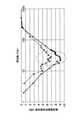
なお、周波数ホッピングの周期は、対応する通過帯域幅の参照帯域の逆数と概ね一致するように、定めたほうが好ましい。図6は、周期と漏洩磁界低減効果の関係を示す図である。横軸が、約200Hzの通過帯域幅に対応する周波数を対象に、遷移幅が400Hzで一定の12個の遷移値を用いて行われた周波数ホッピングの周期を示す。縦軸が、当該周期における漏洩磁界低減効果の値を示す。周波数ホッピングの周期が5msecのあたりにおいて、グラフが最小となり、漏洩磁界低減効果が最も得られていることが分かる。このことから、周波数ホッピングの周期を、対象の周波数に対応する通過帯域幅の参照帯域の逆数と概ね一致させると、良好な低減効果を得られることが分かる。 It is preferable that the frequency hopping cycle is set so as to substantially match the reciprocal of the reference band of the corresponding pass band width. FIG. 6 is a diagram showing the relationship between the period and the leakage magnetic field reduction effect. The horizontal axis shows the period of frequency hopping performed using 12 transition values having a constant transition width of 400 Hz for a frequency corresponding to a pass bandwidth of about 200 Hz. The vertical axis shows the value of the leakage magnetic field reduction effect in the cycle. When the frequency hopping cycle is around 5 msec, the graph becomes the minimum, and it can be seen that the leakage magnetic field reduction effect is most obtained. From this, it can be seen that a good reduction effect can be obtained by roughly matching the frequency hopping cycle with the reciprocal of the reference band of the pass band corresponding to the target frequency.
ゆえに、第1パラメータセットに含まれる周期は、約5msec(1/200Hz)が好ましく、第2パラメータセットに含まれる周期は、約111μsec(1/9kHz)が好ましい。図5(A)では、一つの周波数の維持時間を12.13μsecに設定することにより、遷移値の周期は97μsecとなっている。ゆえに、遷移値の周期が、前述の好ましい周期と概ね一致する。 Therefore, the period included in the first parameter set is preferably about 5 msec (1/200 Hz), and the period included in the second parameter set is preferably about 111 μsec (1/9 kHz). In FIG. 5A, the cycle of the transition value is 97 μsec by setting the maintenance time of one frequency to 12.13 μsec. Therefore, the period of the transition value generally coincides with the above-mentioned preferable period.
また、漏洩磁界低減効果が最大値よりも3dB程度小さいあたりまでを有効な範囲(図6では、漏洩磁界低減効果が-7dBよりも下の範囲)と定めた場合は、周期が、参照帯域の逆数の4分の1倍から、前記第1通過帯域幅の参照帯域の逆数の2倍までの範囲(1/(4RBW)から2/RBWまで)に含まれるようにする。 If the effective range is defined as the range where the leakage magnetic field reduction effect is about 3 dB smaller than the maximum value (in FIG. 6, the leakage magnetic field reduction effect is below -7 dB), the period is the reference band. It is included in the range (from 1 / (4RBW) to 2 / RBW) from 1/4 of the reciprocal to 2 times the reciprocal of the reference band of the first pass bandwidth.
図7は、周波数ホッピングによる漏洩磁界低減効果の低下を示す図である。横軸が周波数を示し、縦軸が漏洩磁界低減効果を示す。漏洩磁界低減効果は、負の値が大きい程(下に行く程)、効果が大きく、漏洩磁界が低減されていることを示す。点線のグラフは、遷移幅が400kHzで一定の六つの遷移値を用いた場合の漏洩磁界低減効果を示す。この場合の拡散帯域幅は2.4GHzである。実線のグラフは、遷移幅が800kHzで一定の六つの遷移値を用いた場合の漏洩磁界低減効果を示す。この場合の拡散帯域幅は4.8GHzであり、実線のグラフに係る周波数帯域の2倍である。 FIG. 7 is a diagram showing a decrease in the leakage magnetic field reduction effect due to frequency hopping. The horizontal axis shows the frequency, and the vertical axis shows the leakage magnetic field reduction effect. The effect of reducing the leaked magnetic field indicates that the larger the negative value (the lower the value), the greater the effect and the reduced the leaked magnetic field. The dotted line graph shows the effect of reducing the leakage magnetic field when the transition width is 400 kHz and six constant transition values are used. The diffusion bandwidth in this case is 2.4 GHz. The solid line graph shows the effect of reducing the leakage magnetic field when the transition width is 800 kHz and six constant transition values are used. The diffusion bandwidth in this case is 4.8 GHz, which is twice the frequency band according to the solid line graph.
図7に示すように、周波数帯域4.8GHzでの漏洩磁界低減効果は、周波数帯域2.4GHzでの漏洩磁界低減効果よりも概ね3dB程度高い。漏洩電磁界低減効果が最大値よりも3dB程度小さいあたりまでを有効な範囲としたが、これはその低下を3dB以内に抑えれば、拡散帯域幅の半分以上の効果は得られているからである。したがって、周期を、対応する通過帯域幅の参照帯域の逆数の4分の1倍から、参照帯域の逆数の2倍までの範囲にしてもよい。 As shown in FIG. 7, the leakage magnetic field reduction effect in the frequency band of 4.8 GHz is approximately 3 dB higher than the leakage magnetic field reduction effect in the frequency band of 2.4 GHz. The effective range is that the leakage electromagnetic field reduction effect is about 3 dB smaller than the maximum value, because if the decrease is suppressed to within 3 dB, the effect of more than half of the diffusion bandwidth can be obtained. be. Therefore, the period may range from a quarter of the reciprocal of the reference band of the corresponding passband to twice the reciprocal of the reference band.
送電制御部14は、記憶部13から、第1パラメータセットまたは第2パラメータセットを取得する。取得するパラメータセットの指定方法は、適宜定めてよい。例えば、当該取得を判断するための指標に基づき、指定してもよい。例えば、指標の値が0のときは、第1パラメータセットを取得し、指標の値が1のときは、第2パラメータセットを取得するとしてもよい。あるいは、指標の値として周波数帯域が示されており、送電制御部14が、当該周波数帯域が帯域AおよびBのいずれに該当するかを判定し、該当すると判定された分類帯域に係るパラメータセットを取得してもよい。基本波および高周波に対応する通過帯域幅が異なるという前提である場合には、指標の値として、基本波または高周波が示されていてもよい。こうして、測定に係る通過帯域幅が基本波と高周波とで異なる場合においても、適切な周波数ホッピングを行うことができる。 The power
当該指標は、ユーザからの入力を受け付けて、書き換えられるようにする。基本波および高調波のいずれか一方が周波数拡散効果を得られなかった場合に、ユーザが当該指標を書き換えることにより、当該一方を対象として周波数ホッピングが行われる。このように、基本波および高調波のいずれかにおいて、周波数拡散効果が得られない場合でも、周波数拡散効果が得られない方に対象を切り替えることにより、対象の周波数拡散効果を得ることができる。 The index accepts input from the user and is rewritten. When either the fundamental wave or the harmonic cannot obtain the frequency spread effect, the user rewrites the index to perform frequency hopping for the one. As described above, even if the frequency diffusion effect cannot be obtained in either the fundamental wave or the harmonic, the frequency diffusion effect of the target can be obtained by switching the target to the one in which the frequency diffusion effect cannot be obtained.
当該指標は記憶部13に記憶されていて、送電制御部14は、まず当該指標を記憶部13から取得し、その後、当該指標に対応するパラメータセットを取得してもよい。 The index may be stored in the
送電制御部14は、取得したパラメータセットに基づく周波数ホッピングが行われるように送電部15を制御する。制御の仕方は、適宜定めてよい。例えば、送電制御部14は、クロック信号をそのまま送電部15に送信することにより、遷移のタイミングを指定してもよい。あるいは、クロック信号を分周して、後述する送電部15内のインバータ1512を動作させる周期の信号を生成し送信することにより、指定されてもよい。遷移値は、予め送電部15に送信しておいてもよいし、遷移させる度に送信してもよい。 The power
送電部15は、送電制御部14の制御により、所望の周波数の磁界を生成する。具体的には、高周波電流生成部151が、指定された周波数にて高周波信号を生成する。そして、送電コイル152が、高周波電流が流れることにより、磁界を発生させる。つまり、高周波電流の周波数は、磁界の周波数と同一である。 The
高周波電流生成部151は、回路にて実現してもよい。例えば、高周波電流生成部151は、インバータ、整流器、力率改善回路(PFC)、電圧変換回路などを含んでいてもよい。図8は、高周波電流生成部の内部構成の一例を示す図である。図8における高周波電流生成部151は、DC-DCコンバータ1511と、インバータ1512と、フィルタ1513と、補償回路1514と、を備える。なお、高周波電流生成部151の構成は、図8の例に限られるわけではない。 The high frequency
DC-DCコンバータ1511は、入力される直流電流を所望の電圧に制御(昇圧または降圧)する。このように、電圧値を制御することにより、受電装置2に電力伝送される電力量を調整する。 The DC-
インバータ1512は、入力される直流電流を、指定された周波数の交流電流に、指定されたタイミングで変換する。これにより、高周波電流の生成および周波数ホッピングが行われる。 The
フィルタ1513はインバータ1512から出力された高周波電流の不要高調波を抑圧する。なお、フィルタ1513により、不要な高調波を抑圧しても、漏洩磁界の強度を低下させることができる。しかし、高調波は、伝送電力の増大に伴い大きくなる。非接触電力伝送は、電気乗用車の充電に用いられており、今後も伝送電力の増大化が見込まれる。ゆえに、伝送電力の増大化に伴い高性能なフィルタが求められ、フィルタの大型化、装置コストの増加といった問題が生じることが見込まれる。ゆえに、漏洩磁界の強度の調整を、全てフィルタ1513により賄うのではなく、本実施形態のように周波数ホッピングを行った方が好ましい。 The
補償回路1514は、高周波電流が送電コイル152に送られる前の力率改善、高周波電流と電圧の位相差軽減などを目的に、高周波電流を補償する。補償回路1514は例えばキャパシタなどから構成される。キャパシタは、送電コイル152に直列に接続されてもよいし、並列に接続されてもよい。このようにして、生成および調整された高周波電流が、送電コイル152に送られる。 The
送電コイル152は、高周波電流が流れることにより磁界を発生させる。送電コイル152から発生した磁界が、受電コイル211に到達すると、送電コイル152と受電コイル211との間で相互結合が生じる。これにより、受電コイル211は、送電コイル152からの電力を受け取る。このようにして、非接触で電力が伝送される。 The
なお、コイルの種類は、巻線とフェライトコアの配置などから、ソレノイド型と、スパライラル型があるが、いずれの型でもよい。 There are two types of coils, solenoid type and helical type, depending on the arrangement of windings and ferrite cores, but any type may be used.
以上のようにして、送電装置1は、周波数ホッピングの対象とする周波数に応じたパラメータセットを用いて周波数ホッピングを行いつつ、受電装置2に対し送電を行うことができる。 As described above, the
受電装置2は、相互誘導により受電コイル211に生じた電力を受け取る。受電コイル211の種類は、送電コイル152同様、いずれの型でもよい。 The
整流部212は、受電コイル211からの高周波電流を整流し、バッテリー、他の装置などに流すためのものである。図9は、整流部の内部構成の一例を示す図である。整流部212は、補償回路2121と、フィルタ2122と、整流回路(リップ除去回路)2123と、DC-DCコンバータ2124と、を備える。なお、整流部212の構成は、高周波電流を整流することができればよく、図9の例に限られるわけではない。 The rectifying
受電コイル211からの高周波電流は、補償回路2121およびフィルタ2122を介して、整流器2123へ伝送される。補償回路2121もキャパシタなどにより構成されていてもよく、当該キャパシタは、受電コイル211に直列に接続されていても、並列に接続されていてもよい。フィルタ2122も、キャパシタ、インダクタ、またはこれらの組み合わせから構成されていてもよい。また、電磁妨害に対する磁界強度が許容値に対して十分に低い場合は、フィルタ2122はなくてもよい。 The high frequency current from the
整流器2123は、例えば、フルブリッジのダイオードなどにより構成されていてもよい。整流後の電流は、リップル成分を多く含む。ゆえに、整流器2123は、リップルを除去するために、キャパシタ、インダクタ、またはこれらの組み合わせからなるリップル除去回路を含んでいてもよい。DC-DCコンバータ2124は、整流器2123の整流後に電圧変換を行う。そして、整流、変圧等が整流部212により行われた電流が、他の構成要素、例えばバッテリー等に送られる。以上のようにして、受電装置2は受電を行うことができる。 The
以上のように、本実施形態によれば、基本波および高調波のいずれかにおいて、周波数拡散効果が得られない場合でも、周波数拡散効果が得られない方に対象を切り替えることにより、対象の周波数拡散効果を得ることができる。 As described above, according to the present embodiment, even if the frequency diffusion effect cannot be obtained in either the fundamental wave or the harmonic, the target frequency is switched to the one in which the frequency diffusion effect cannot be obtained. A diffusion effect can be obtained.
非接触電力伝送システムの漏洩磁界は、シールドルーム等の実験室内で許容値を満たしているかの検証や最終設置場所での測定が必要となる。シールドルームや設置場所にて許容値を満たしていないことが判明した場合、その場で対策を行い、許容値以下とすることも必要となってくる。 It is necessary to verify whether the leakage magnetic field of the non-contact power transmission system meets the allowable value in a laboratory such as a shield room and to measure it at the final installation location. If it is found that the allowable value is not met in the shield room or the installation location, it is necessary to take measures on the spot and make it below the allowable value.
漏洩磁界低減の対象は基本波および高調波であり、シールドルームや設置場所の環境でどちらに周波数拡散による低減を適用するか、測定を実施しながら調整することも必要となる。本実施形態によれば、そのような事態に対しても、即座に対応可能なように、対象を基本波から高周波に、または、高周波から基本波に切り替えることができる。 The target of leakage magnetic field reduction is the fundamental wave and harmonics, and it is also necessary to adjust while performing measurement which of the shield room and the environment of the installation site to apply the reduction by frequency diffusion. According to the present embodiment, the target can be switched from the fundamental wave to the high frequency or from the high frequency to the fundamental wave so that such a situation can be dealt with immediately.
(第2の実施形態)
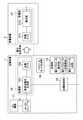
図10は、第2の実施形態に係る電力伝送システムの一例を示すブロック図である。第2の実施形態は、第1の実施形態の記憶部13が複数に分けられている点と、スイッチ16およびスイッチ制御部を新たに備えている点が第1の実施形態とは異なる。第1の実施形態と同様な点は、説明を省略する。(Second embodiment)
FIG. 10 is a block diagram showing an example of the power transmission system according to the second embodiment. The second embodiment is different from the first embodiment in that the
第1実施形態の記憶部13は、通過帯域幅ごとに分けられおり、それぞれ対応する通過帯域幅において用いられるパラメータセットを記憶している。図2の例では、第1パラメータセットを記憶する第1記憶部13Aと、第2パラメータセットを記憶する第2記憶部13Bと、が示されている。 The
スイッチ16は、複数の記憶部13と、送電制御部14と、に接続されており、スイッチングにより、複数の記憶部13のいずれかと、送電制御部14と、を電気的に接続する。スイッチ制御部17は、外部からの入力を受け付けて、送電制御部14が当該入力に対応する記憶部13と接続されるように、スイッチ16を制御する。例えば、電気信号を受け付けて、スイッチ16を切り替えるようにしてもよい。あるいは、スイッチ制御部は、単なるスイッチレバーであってもよい。その場合、ユーザは、スイッチレバーを切り替えるだけで、使用するパラメータセットを切り替えることができる。 The
あるいは、スイッチ制御部に対して、通過帯域幅、周波数ホッピングの対象とする周波数などの情報が入力されて、スイッチ制御部が入力された情報から接続すべき記憶部13を判断してもよい。 Alternatively, information such as a pass bandwidth and a frequency to be frequency hopping may be input to the switch control unit, and the switch control unit may determine the
送電制御部14は、1つの記憶部13としか電気的に接続されておらず、その電気的に接続された記憶部13が記憶するパラメータセットを取得する。ゆえに、本実施形態では、送電制御部14は、いずれのパラメータセットを取得するかを判断せず、前述の指標は省略されてよい。送電制御部14が、取得したパラメータセットに基づき、送電部を制御する点は、第1の実施形態と同様である。 The power
以上のように、第2の実施形態によれば、スイッチにより送電制御部14の接続先を切り替えることにより、使用するパラメータセットを容易に切り替えることができる。 As described above, according to the second embodiment, the parameter set to be used can be easily switched by switching the connection destination of the power
(第3の実施形態)
これまでの実施形態では、基本波および高調波の対応する通過帯域幅が異なる場合、基本波および高調波のいずれかにおいて周波数拡散効果が得られないため、周波数拡散効果を得たい方に、周波数ホッピングの対象を切り替えた。一方、本実施形態では、基本波および高調波の対応する通過帯域幅が異なる場合でも、基本波と高調波の両方に対して周波数拡散効果が得られるような周波数ホッピングを実行する。(Third embodiment)
In the previous embodiments, when the corresponding passband widths of the fundamental wave and the harmonics are different, the frequency spreading effect cannot be obtained in either the fundamental wave or the harmonic, so that the frequency is used for those who want to obtain the frequency spreading effect. The target of hopping was switched. On the other hand, in the present embodiment, even when the corresponding passband widths of the fundamental wave and the harmonics are different, frequency hopping is performed so that the frequency spreading effect can be obtained for both the fundamental wave and the harmonics.
図11は、第3の実施形態に係る電力伝送システムの一例を示すブロック図である。第3の実施形態は、送電装置がパラメータセット生成部18をさらに備える点が、第1の実施形態とは異なる。第1の実施形態と同様な点は、説明を省略する。 FIG. 11 is a block diagram showing an example of the power transmission system according to the third embodiment. The third embodiment is different from the first embodiment in that the power transmission device further includes the parameter set
パラメータセット生成部18は、基本波および高周波の双方で周波数拡散効果が得られるパラメータセットを算出する。当該パラメータセットを第3パラメータセットと記載し、第3パラメータセットによる周波数ホッピングを混合拡散と記載する。 The parameter set
前述の通り、周波数ホッピングの周期は、通過帯域幅の参照帯域の逆数と概ね一致することが好ましい。ゆえに、第1パラメータによる周波数ホッピングの周期は約5msec(1/200Hz)程度が適しており、第2パラメータによる周波数ホッピングの周期は約0.1msec(1/9kHz)程度が適しており、適する周期が1桁以上異なる。ゆえに、遷移値が、約0.1msecの周期で遷移しつつ、約5msecの周期でも遷移しているような、周波数ホッピングを行えば、基本波および高調波の対応する通過帯域幅が異なる場合でも、基本波と高調波の両方に対して周波数拡散効果が得られる。 As mentioned above, it is preferable that the frequency hopping cycle substantially coincides with the reciprocal of the reference band of the passband. Therefore, the cycle of frequency hopping by the first parameter is suitable to be about 5 msec (1/200 Hz), and the cycle of frequency hopping by the second parameter is suitable to be about 0.1 msec (1/9 kHz). Is different by one digit or more. Therefore, if frequency hopping is performed such that the transition value transitions in a cycle of about 0.1 msec and also in a cycle of about 5 msec, even if the corresponding passband widths of the fundamental wave and the harmonics are different. , A frequency spread effect can be obtained for both fundamentals and harmonics.
図12は、第3パラメータセットについて説明する図である。図12(A)は、第1パラメータによる周波数ホッピングにおける周波数の遷移(長周期の周波数遷移)を示す図である。図12(B)は、第2パラメータによる周波数ホッピングにおける周波数の遷移(短周期の周波数遷移)を示す図である。図12(A)の長周期の周波数ホッピングでは、遷移幅が300Hzで一定のfN1からfN8までの遷移値が用いられている。長周期の周波数ホッピングの周期は、約5msec(5000μsec)である。図12(B)の短周期の周波数ホッピングでは、遷移幅が1200Hzで一定のfH1からfH4までの遷移値を用いて行われている。長周期の周波数ホッピングの周期は、約0.1msec(100μsec)である。なお、ここでは、fN1とfH1は同じ値としている。また、遷移幅がちょうど4倍であるから、fH1=fN1、fH2=fN6、fH3=fN11、fH4=fN16である。FIG. 12 is a diagram illustrating a third parameter set. FIG. 12A is a diagram showing a frequency transition (long-period frequency transition) in frequency hopping according to the first parameter. FIG. 12B is a diagram showing a frequency transition (short-period frequency transition) in frequency hopping according to the second parameter. In the long-period frequency hopping of FIG. 12A, a transition value from fN1 to fN8 having a constant transition width of 300 Hz is used. The period of long-period frequency hopping is about 5 msec (5000 μsec). In the short-period frequency hopping shown in FIG. 12B, a transition value from fH1 to fH4 having a constant transition width of 1200 Hz is used. The period of long-period frequency hopping is about 0.1 msec (100 μsec). Here, fN1 and fH1 have the same value. Further, since the transition width is exactly four times, fH1 = fN1 , fH2 = fN6 , fH3 = fN11 , and fH4 = fN16 .
図12(C)は、混合拡散における周波数の遷移を示す図である。図12(A)のような長周期の周波数遷移と、図12(B)に示すような短周期の周波数遷移と、を合成すると、短周期の周波数遷移に、長周期の周波数遷移がオフセットとして載っているような図12(C)のような周波数遷移を行うことができる。図12(C)に示すように、混合拡散における遷移値はfA1からfA23までとなっている。FIG. 12C is a diagram showing frequency transitions in mixed diffusion. When the long-period frequency transition as shown in FIG. 12 (A) and the short-period frequency transition as shown in FIG. 12 (B) are combined, the short-period frequency transition is offset by the long-period frequency transition. It is possible to perform the frequency transition as shown in FIG. 12 (C). As shown in FIG. 12C, the transition values in the mixed diffusion are from fA1 to fA23 .
図12(D)は、図12(C)の点線枠で囲まれた部分を示したものである。図12(D)に示すように、周波数は、当初、{fA1、fA6、fA11、fA16、fA16、fA11、fA6、fA1}の組み合わせにおいて、当該組み合わせ内で周期的に遷移している。この遷移は、短周期の遷移と同じであり、当該周期は、約100μsec(0.1msec)であり、1回あたりの遷移幅は1200Hzである。FIG. 12D shows a portion surrounded by a dotted line frame in FIG. 12C. As shown in FIG. 12 (D), the frequency is initially periodic within the combination of {fA1 , fA6 , fA11 , fA16 , fA16 , fA11 , fA6 , fA1 }. Has transitioned to. This transition is the same as the transition of a short cycle, the cycle is about 100 μsec (0.1 msec), and the transition width per one time is 1200 Hz.
その後、一定時間経過した時点で、{fA2、fA7、fA12、fA17、fA17、fA12、fA7、fA2}の組み合わせにおいて、当該組み合わせ内で周期的に遷移している。その後、再び一定時間経過して時点で、{fA3、fA8、fA13、fA18、fA18、fA13、fA8、fA3}の組み合わせにおいて、当該組み合わせ内で周期的に遷移している。このように、一定時間経過する度に、組み合わせの構成要素、つまり用いられる遷移値の番号が一つ増加している。整数iを用いると、i番目の組み合わせFAiはFAi={fAi、fAi+5、fAi+10、fAi+15、fAi+15、fAi+10、fAi+5、fAi}と表すことができる。そして、8番目の組み合わせFA8{fA8、fA13、fA18、fA23、fA23、fA18、fA13、fA8}まで増加し、8番目の組み合わせF8以降は、降順にて組み合わせが遷移する。こうして、組み合わせFAiの遷移が周期的に繰り返されている。この組み合わせの遷移は、長周期の遷移と同じであり、当該周期は、約5000μsec(5msec)、組み合わせの1回あたりの遷移幅は300Hzである。After that, when a certain period of time has elapsed, the combination of {fA2 , fA7 , fA12 , fA17 , fA17 , fA12 , fA7 , fA2 } is periodically transitioned within the combination. Then, after a certain period of time has passed again, in the combination of {fA3 , fA8 , fA13 , fA18 , fA18 , fA13 , fA8 , fA3 }, the transition is periodically made within the combination. There is. In this way, each time a certain period of time elapses, the number of the component of the combination, that is, the transition value used is increased by one. Using the integer i, the i-th combination FAi can be expressed as FAi = {fAi, fAi + 5, fAi + 10, fAi + 15, fAi + 15, fAi + 10, fAi + 5, fAi }. Then, the number increases to the 8th combinationFA8 {fA8 ,fA13 ,fA18 ,fA23 ,fA23 ,fA18 ,fA13 ,fA8 }, and the8th combination F8 and subsequent combinations are combined in descending order. Transitions. In this way, the transition of the combinationFAi is periodically repeated. The transition of this combination is the same as the transition of a long period, the period is about 5000 μsec (5 msec), and the transition width per combination is 300 Hz.
このように、図12(C)および10(D)に示した周波数遷移は、約0.1msecの短周期にて遷移する成分(組合せFAi内の構成要素)と、約5msecの長周期にて遷移する成分(組合せFAi)を有している。ゆえに、基本波および高調波の対応する通過帯域幅が異なる場合でも、約0.1msecの短周期により、高周波に対する周波数拡散効果が得られ、約5msecの長周期により、基本波に対する周波数拡散効果が得られる。ゆえに、このような短周期と長周期の双方を有する第3パラメータセットを用いることにより、基本波および高周波の双方で周波数拡散効果が得られる。As described above, the frequency transitions shown in FIGS. 12 (C) and 10 (D) have a component (component in the combinationFAi ) that transitions in a short cycle of about 0.1 msec and a long cycle of about 5 msec. It has a component (combinationFAi ) that transitions to. Therefore, even if the corresponding passband widths of the fundamental wave and the harmonics are different, the frequency diffusion effect for the high frequency can be obtained with a short period of about 0.1 msec, and the frequency diffusion effect for the fundamental wave can be obtained with a long period of about 5 msec. can get. Therefore, by using the third parameter set having both the short period and the long period, the frequency diffusion effect can be obtained in both the fundamental wave and the high frequency.
パラメータセット生成部18は、第1パラメータセットと、第2パラメータと、に基づき、図12(C)のように周波数が遷移するような周波数ホッピングを行うための第3パラメータセットを決定する。第1パラメータセットによる周波数遷移と、第2パラメータセットによる周波数遷移と、による合成波を生成した上で、当該合成波から、第3パラメータセットを導出すればよい。しかし、単なる合成波では、不具合が生じることもあるため、次の条件を満たすようにする。 The parameter set
第1の条件は、これまでの実施形態と同様、短周期の拡散帯域幅が、長周期の拡散帯域幅よりも広くなるようにすることである。短周期の拡散帯域幅は、同じ組み合わせ内の最小遷移値と最大遷移値までの間隔であり、fAiからfAi+15までである。長周期の拡散帯域幅は、1番目の組み合わせのj(jは1以上の整数)番目の遷移値と、周波数が最も増加した組み合わせのj番目の遷移値までの間隔である。つまり、図12の例では、fA1からfA8、fA6からfA13、fA11からfA18、fA16からfA23のいずれかを意味する。The first condition is that the short-period diffusion bandwidth is wider than the long-period diffusion bandwidth, as in the previous embodiments. The short-period diffusion bandwidth is the interval between the minimum and maximum transition values within the same combination, fromfAi tofAi + 15 . The long-period diffusion bandwidth is the interval between the j-th transition value of the first combination (j is an integer of 1 or more) and the j-th transition value of the combination with the highest frequency. That is, in the example of FIG. 12, it means any one of fA1 to fA8 , fA6 to fA13 , fA11 to fA18 , and fA16 to fA23 .
第2の条件は、これまでの実施形態と同様、短周期の遷移幅が、長周期の遷移幅よりも小さくなるようにすることである。図12の例では、短周期の遷移幅は1200Hzであり、長周期の遷移幅は300Hzであったため、図12の例では、第1パラメータセットおよび第2パラメータセットに含まれる遷移値をそのまま用いればよい。 The second condition is that the short-period transition width is smaller than the long-period transition width, as in the previous embodiments. In the example of FIG. 12, the short-period transition width was 1200 Hz and the long-period transition width was 300 Hz. Therefore, in the example of FIG. 12, the transition values included in the first parameter set and the second parameter set are used as they are. Just do it.
第3の条件は、混合拡散による拡散帯域幅が、許容可能な帯域幅に含まれるようにすることである。短周期の拡散帯域幅と、長周期の拡散帯域幅とが、許容可能な帯域幅に含まれていたとしても、混合拡散による拡散帯域幅が許容可能な帯域幅に含まれるとは限らないためである。例えば、混合拡散における最大の遷移値は、8番目の組み合わせFA8の最大値であるfA23である。このfA23は、長周期に対する周波数ホッピングの最大の遷移値fN8に対して、短周期に対する周波数ホッピングの最大の遷移値と最小の遷移値との差分fH4-fH1(fN16-fN1)が合算された値である。ゆえに、fA23=fN8+fH4-fH1(fN8+fN16-fN1)が成り立つ。ゆえに、長周期に対する周波数ホッピングの最大の遷移値と、短周期に対する周波数ホッピングの最大の遷移値と最小の遷移値との差分との総和が、混合拡散に利用可能な帯域幅の上限値を超えないようにする必要がある。The third condition is to ensure that the diffusion bandwidth due to mixed diffusion is included in the acceptable bandwidth. Even if the short-period diffusion bandwidth and the long-period diffusion bandwidth are included in the acceptable bandwidth, the diffusion bandwidth due to mixed diffusion is not necessarily included in the acceptable bandwidth. Is. For example, the maximum transition value in mixed diffusion is fA23 , which is the maximum value of the eighth combinationFA8 . This fA23 is the differencebetween the maximum transition value of frequency hopping for a long period and the minimum transition value of frequency hopping for a short period f H4- fH1 (fN16 -fN1 ). ) Is the total value. Therefore, fA23 = fN8 + fH4 −fH1 (fN8 + fN16 −fN1 ) holds. Therefore, the sum of the maximum transition value of frequency hopping for a long period and the difference between the maximum and minimum transition values of frequency hopping for a short period exceeds the upper limit of the bandwidth available for mixed diffusion. You need to avoid it.
なお、高調波の周波数帯域の両端に、遷移幅の半分程度の帯域を、マージン(使用しない帯域)として設けてもよい。高調波に対する周波数ホッピングにおける想定される遷移幅(例えば2kHz程度)では、周波数の遷移に伴い、周波数スペクトルのサイドローブの広がりが生じる。ゆえに、マージンを設けることにより、サイドローブの影響を受けないようにしてもよい。その場合、高調波の周波数帯域の上限値からマージンを引いた値が、混合拡散における最大の遷移値に対する上限値となる。 A band of about half the transition width may be provided as a margin (unused band) at both ends of the frequency band of the harmonics. At the assumed transition width (for example, about 2 kHz) in frequency hopping with respect to harmonics, the side lobe of the frequency spectrum expands with the frequency transition. Therefore, by providing a margin, it may not be affected by the side lobe. In that case, the value obtained by subtracting the margin from the upper limit value of the frequency band of the harmonic becomes the upper limit value for the maximum transition value in the mixed diffusion.
パラメータセット生成部18は、合成波が上記の条件を満たさない場合は、上記の条件を満たすように、合成波のパラメータを変更すればよい。変更方法は、任意に定めてよい。 If the composite wave does not satisfy the above conditions, the parameter set
パラメータセット生成部18は、生成された第3パラメータセットを記憶部13に送信する。これにより、記憶部13は、第3パラメータセットも記憶する。なお、直接、第3パラメータセットが、パラメータセット生成部18から送電制御部14に直接送られてもよい。 The parameter set
送電制御部14は、第3パラメータセットを使用するように入力された場合、記憶部13から第3パラメータセットを取得し、第3パラメータセットに基づく周波数ホッピングを行うように、送電部15を制御する。第3パラメータセットの指定は、第1の実施形態で示された指標を用いてもよいし、第2の実施形態で示されたように、第3パラメータセットのみを記憶する記憶部と送電制御部14とをスイッチ16で接続してもよい。これにより、基本波および高調波の対応する通過帯域幅が異なる場合でも、基本波と高調波の両方に対して周波数拡散効果が得られるような周波数ホッピングを実行することができる。 When the power
なお、上記では、パラメータセット生成部18が第3パラメータセットを生成するとした。しかし、第3パラメータセットを外部で生成する場合も想定される。当該想定においては、パラメータセット生成部18は省略されてもよく、また、記憶部13は、第3パラメータだけを記憶していてもよい。 In the above, it is assumed that the parameter set
以上のように、第3の実施形態によれば、基本波および高周波の双方で周波数拡散効果が得られる第3パラメータセットが生成される。そして、第3パラメータセットによる周波数ホッピングが行われることにより、基本波および高調波の双方で周波数拡散の効果を得ることができる。 As described above, according to the third embodiment, the third parameter set in which the frequency diffusion effect is obtained in both the fundamental wave and the high frequency is generated. Then, by performing frequency hopping by the third parameter set, the effect of frequency diffusion can be obtained in both the fundamental wave and the harmonics.
また、記憶部13に第1から第3までのパラメータセットが記憶されている場合、電力伝送を実行するユーザは、基本波に対する周波数ホッピングと、高調波に対する周波数ホッピングと、基本波および高調波の双方に対する周波数ホッピングと、の三つの選択肢から、実行する周波数ホッピングを選択することができる。これにより、テスト環境、設置現場などの状況に応じた調整を、より容易に行うことが可能となる。 Further, when the
なお、本実施形態の各処理は専用の回路で実現されることを想定しているが、周波数を変更するタイミングの指定など、回路の制御に関する処理は、CPUがメモリに格納されたプログラムを実行することにより実現されてもよい。 It is assumed that each process of the present embodiment is realized by a dedicated circuit, but the CPU executes a program stored in the memory for the process related to the circuit control such as the specification of the timing to change the frequency. It may be realized by doing.
上記に、本発明の一実施形態を説明したが、これらの実施形態は、例として提示したものであり、発明の範囲を限定することは意図していない。これら新規な実施形態は、その他の様々な形態で実施されることが可能であり、発明の要旨を逸脱しない範囲で、種々の省略、置き換え、変更を行うことができる。これら実施形態やその変形は、発明の範囲や要旨に含まれるとともに、特許請求の範囲に記載された発明とその均等の範囲に含まれる。 Although one embodiment of the present invention has been described above, these embodiments are presented as examples and are not intended to limit the scope of the invention. These novel embodiments can be implemented in various other embodiments, and various omissions, replacements, and changes can be made without departing from the gist of the invention. These embodiments and variations thereof are included in the scope and gist of the invention, and are also included in the scope of the invention described in the claims and the equivalent scope thereof.
1 送電装置
11 AC電源
12 AC-DCコンバータ
13 記憶部
13A 第1記憶部
13B 第2記憶部
14 送電制御部
15 送電部
151 高周波電流生成部
1511 高周波電流生成部のDC-DCコンバータ
1512 インバータ
1513 高周波電流生成部のフィルタ
1514 高周波電流生成部の補償回路
152 送電コイル
16 スイッチ16
17 スイッチ制御部
18 パラメータセット生成部
2 受電装置
21 受電部
211 受電コイル
212 整流部
2121 整流部の補償回路
2122 整流部のフィルタ
2123 整流器
2124 整流部のDC-DCコンバータ1
17
Claims (15)
Translated fromJapanese第1周波数帯域に対する周波数ホッピングに係る第1パラメータセットと、第2周波数帯域に対する周波数ホッピングに係る第2パラメータセットと、を記憶する記憶部と、
前記第1パラメータセットおよび前記第2パラメータセットの一方に基づく周波数ホッピングのため、前記送電部を制御する送電制御部と、
を備え、
前記第1周波数帯域が、漏洩磁界を測定するための所定の規格に基づく第1通過帯域幅に対応する帯域であり、
前記第2周波数帯域が、前記規格に基づく、前記第1通過帯域幅よりも高帯域を対象とした第2通過帯域幅に対応する帯域である
送電装置。A power transmission unit that generates a magnetic field,
A storage unit that stores a first parameter set related to frequency hopping for the first frequency band and a second parameter set related to frequency hopping for the second frequency band.
A power transmission control unit that controls the power transmission unit for frequency hopping based on one of the first parameter set and the second parameter set.
Equipped with
The first frequency band is a band corresponding to a first pass bandwidth based on a predetermined standard for measuring a leakage magnetic field.
A power transmission device in which the second frequency band corresponds to a second passband, which is based on the standard and targets a band higher than the first passband.
前記送電部を制御して、第1周波数帯域に対する周波数ホッピングに係る第1パラメータセットに基づく周波数ホッピングと、第2周波数帯域に対する周波数ホッピングに係る第2パラメータセットに基づく周波数ホッピングと、を少なくとも実行可能とする送電制御部と、
を備え、
前記第1周波数帯域が、漏洩磁界を測定するための所定の規格に基づく第1通過帯域幅に対応する帯域であり、
前記第2周波数帯域が、前記規格に基づく、前記第1通過帯域幅よりも高帯域を対象とした第2通過帯域幅に対応する帯域である
送電装置。A power transmission unit that generates a magnetic field,
By controlling the transmission unit, it is possible to at least execute frequency hopping based on the first parameter set related to frequency hopping for the first frequency band and frequency hopping based on the second parameter set related to frequency hopping for the second frequency band. And the transmission control unit
Equipped with
The first frequency band is a band corresponding to a first pass bandwidth based on a predetermined standard for measuring a leakage magnetic field.
A power transmission device in which the second frequency band corresponds to a second passband, which is based on the standard and targets a band higher than the first passband.
請求項1または2に記載の送電装置。The power transmission device according to claim 1 or 2, wherein the power transmission control unit switches a parameter set to be acquired according to an external input.
前記送電制御部、前記第1記憶部、および前記第2記憶部に、接続されたスイッチをさらに備え、
前記スイッチが、前記送電制御部を、前記第1記憶部および前記第2記憶部のいずれかと電気的に接続し、
前記送電制御部が、電気的に接続された前記第1記憶部または前記第2記憶部が記憶するパラメータセットを取得する
請求項1、または、請求項1に従属する請求項3、に記載の送電装置。The storage unit includes a first storage unit that stores the first parameter set and a second storage unit that stores the second parameter set.
A switch connected to the power transmission control unit, the first storage unit, and the second storage unit is further provided.
The switch electrically connects the power transmission control unit to either the first storage unit or the second storage unit.
The third aspect of the present invention, wherein the power transmission control unit acquires a parameter set stored by the first storage unit or the second storage unit electrically connected to the power transmission control unit, or claim3 which is subordinate to the first storage unit. Power transmission device.
第3パラメータセットに基づき、周波数ホッピングが行われるように、前記送電部を制御する送電制御部と、
を備え、
前記周波数ホッピングによる周波数の遷移が、第1周期で遷移する第1成分と、第2周期で遷移する第2成分と、を含み、
前記第1周期が、漏洩磁界を測定するための所定の規格に基づく第1通過帯域幅の参照帯域の逆数と概ね一致し、
前記第2周期が、前記規格に基づく、前記第1通過帯域幅よりも高帯域を対象とした第2通過帯域幅の参照帯域の逆数と概ね一致する
送電装置。A power transmission unit that generates a magnetic field,
A power transmission control unit that controls the power transmission unit so that frequency hopping is performed based on the third parameter set.
Equipped with
The frequency transition due to the frequency hopping includes a first component that transitions in the first cycle and a second component that transitions in the second cycle.
The first period roughly coincides with the reciprocal of the reference band of the first passband based on a predetermined standard for measuring the leakage magnetic field.
A power transmission device in which the second period substantially matches the reciprocal of the reference band of the second passband for a band higher than the first passband based on the standard.
基本波およびn次高調波の両方において、周波数拡散効果が得られる
請求項5に記載の送電装置。When the fundamental wave of the magnetic field corresponds to the first passband and the n (n is an integer of 2 or more) harmonic of the magnetic field corresponds to the second passband.
The power transmission device according to claim 5, wherein a frequency diffusion effect can be obtained in both the fundamental wave and the nth harmonic.
前記第1パラメータセットおよび前記第2パラメータセットに基づき、前記第3パラメータセットを生成するパラメータセット生成部と、
をさらに備える
請求項5または6に記載の送電装置。A first parameter set related to frequency hopping for the first frequency band corresponding to the first pass bandwidth and a second parameter set related to frequency hopping for the second frequency band corresponding to the second pass bandwidth are stored. Memory unit and
A parameter set generator that generates the third parameter set based on the first parameter set and the second parameter set,
The power transmission device according to claim 5 or 6.
請求項5ないし7のいずれか一項に記載の送電装置。The power transmission device according to any one of claims 5 to 7, wherein the frequency transition value in frequency hopping based on the third parameter set is included in the specified spread bandwidth.
請求項5ないし8のいずれか一項に記載の送電装置。The power transmission device according to any one of claims 5 to 8, wherein the diffusion bandwidth in the first component is smaller than the diffusion bandwidth in the second component.
請求項5ないし9のいずれか一項に記載の送電装置。The power transmission device according to any one of claims 5 to 9, wherein the frequency transition width in the first component is smaller than the frequency transition width in the second component.
前記第2周期が、前記第2通過帯域幅の参照帯域の逆数の4分の1倍から、前記第2通過帯域幅の参照帯域の逆数の2倍までの範囲に含まれる
請求項5ないし10のいずれか一項に記載の送電装置。The first cycle is included in the range from a quarter of the reciprocal of the reference band of the first passband to twice the reciprocal of the reference band of the first passband.
Claims 5 to 10 in which the second period is included in the range from a quarter of the reciprocal of the reference band of the second passband to twice the reciprocal of the reference band of the second passband. The power transmission device according to any one of the above.
請求項5ないし11のいずれか一項に記載の送電装置。The power transmission device according to any one of claims 5 to 11, wherein the graph of the frequency transition in the first component has a triangular wave shape or a sinusoidal shape.
前記送電装置は、
磁界を発生させる送電部と、
第1周波数帯域に対する周波数ホッピングに係る第1パラメータセットと、第2周波数帯域に対する周波数ホッピングに係る第2パラメータセットと、を記憶する記憶部と、 前記第1パラメータセットおよび前記第2パラメータセットの一方に基づく周波数ホッピングのため、前記送電部を制御する送電制御部と、
を備え、
前記受電装置は、
前記磁界により、高周波電流を生成する受電部と、
を備え、
前記第1周波数帯域が、漏洩磁界を測定するための所定の規格に基づく第1通過帯域幅に対応する帯域であり、
前記第2周波数帯域が、前記規格に基づく、前記第1通過帯域幅よりも高帯域を対象とした第2通過帯域幅に対応する帯域である
電力伝送システム。It is a power transmission system that is equipped with a power transmission device and a power receiving device and transmits power in a non-contact manner.
The power transmission device
A power transmission unit that generates a magnetic field,
A storage unit for storing a first parameter set related to frequency hopping for the first frequency band and a second parameter set related to frequency hopping for the second frequency band, and one of the first parameter set and the second parameter set. For frequency hopping based on, the power transmission control unit that controls the power transmission unit and
Equipped with
The power receiving device is
A power receiving unit that generates a high-frequency current by the magnetic field,
Equipped with
The first frequency band is a band corresponding to a first pass bandwidth based on a predetermined standard for measuring a leakage magnetic field.
A power transmission system in which the second frequency band corresponds to a second passband, which is based on the standard and targets a band higher than the first passband.
前記送電装置は、
磁界を発生させる送電部と、
第3パラメータセットに基づき、周波数ホッピングが行われるように、前記送電部を制御する送電制御部と、
を備え、
前記受電装置は、
前記磁界により、高周波電流を生成する受電部
を備え、
前記周波数ホッピングによる周波数の遷移が、第1周期で遷移する第1成分と、第2周期で遷移する第2成分と、を含み、
前記第1周期が、漏洩磁界を測定するための所定の規格に基づく第1通過帯域幅の参照帯域の逆数と概ね一致し、
前記第2周期が、前記規格に基づく、前記第1通過帯域幅よりも高帯域を対象とした第2通過帯域幅の参照帯域の逆数と概ね一致する
電力伝送システム。It is a power transmission system that is equipped with a power transmission device and a power receiving device and transmits power in a non-contact manner.
The power transmission device
A power transmission unit that generates a magnetic field,
A power transmission control unit that controls the power transmission unit so that frequency hopping is performed based on the third parameter set.
Equipped with
The power receiving device is
A power receiving unit that generates a high-frequency current by the magnetic field is provided.
The frequency transition due to the frequency hopping includes a first component that transitions in the first cycle and a second component that transitions in the second cycle.
The first period roughly coincides with the reciprocal of the reference band of the first passband based on a predetermined standard for measuring the leakage magnetic field.
A power transmission system in which the second period substantially matches the reciprocal of the reference band of the second passband for a band higher than the first passband based on the standard.
前記送電装置は、
磁界を発生させる送電部と、
前記送電部を制御して、第1周波数帯域に対する周波数ホッピングに係る第1パラメータセットに基づく周波数ホッピングと、第2周波数帯域に対する周波数ホッピングに係る第2パラメータセットに基づく周波数ホッピングと、を少なくとも実行可能とする送電制御部と、
を備え、
前記受電装置は、
前記磁界により、高周波電流を生成する受電部と、
を備え、
前記第1周波数帯域が、漏洩磁界を測定するための所定の規格に基づく第1通過帯域幅に対応する帯域であり、
前記第2周波数帯域が、前記規格に基づく、前記第1通過帯域幅よりも高帯域を対象とした第2通過帯域幅に対応する帯域である
電力伝送システム。It is a power transmission system that is equipped with a power transmission device and a power receiving device and transmits power in a non-contact manner.
The power transmission device
A power transmission unit that generates a magnetic field,
By controlling the transmission unit, it is possible to at least execute frequency hopping based on the first parameter set related to frequency hopping for the first frequency band and frequency hopping based on the second parameter set related to frequency hopping for the second frequency band. And the transmission control unit
Equipped with
The power receiving device is
A power receiving unit that generates a high-frequency current by the magnetic field,
Equipped with
The first frequency band is a band corresponding to a first pass bandwidth based on a predetermined standard for measuring a leakage magnetic field.
A power transmission system in which the second frequency band corresponds to a second passband, which is based on the standard and targets a band higher than the first passband.
Priority Applications (2)
| Application Number | Priority Date | Filing Date | Title |
|---|---|---|---|
| JP2018045918AJP7002372B2 (en) | 2018-03-13 | 2018-03-13 | Transmission equipment and power transmission system |
| US16/129,086US11005284B2 (en) | 2018-03-13 | 2018-09-12 | Electric power transmission device and electric power transmission system |
Applications Claiming Priority (1)
| Application Number | Priority Date | Filing Date | Title |
|---|---|---|---|
| JP2018045918AJP7002372B2 (en) | 2018-03-13 | 2018-03-13 | Transmission equipment and power transmission system |
Publications (2)
| Publication Number | Publication Date |
|---|---|
| JP2019161866A JP2019161866A (en) | 2019-09-19 |
| JP7002372B2true JP7002372B2 (en) | 2022-01-20 |
Family
ID=67904196
Family Applications (1)
| Application Number | Title | Priority Date | Filing Date |
|---|---|---|---|
| JP2018045918AActiveJP7002372B2 (en) | 2018-03-13 | 2018-03-13 | Transmission equipment and power transmission system |
Country Status (2)
| Country | Link |
|---|---|
| US (1) | US11005284B2 (en) |
| JP (1) | JP7002372B2 (en) |
Cited By (1)
| Publication number | Priority date | Publication date | Assignee | Title |
|---|---|---|---|---|
| KR102064818B1 (en) | 2012-04-27 | 2020-01-10 | 가부시키가이샤 요시노 고교쇼 | Label for in-mold molding and labeled container |
Families Citing this family (5)
| Publication number | Priority date | Publication date | Assignee | Title |
|---|---|---|---|---|
| JP6948990B2 (en) | 2018-07-12 | 2021-10-13 | 株式会社東芝 | Transmission equipment and power transmission system |
| JP7039515B2 (en) | 2019-03-15 | 2022-03-22 | 株式会社東芝 | Transmission equipment, contactless power transmission system and contactless power transmission method |
| JP2021010244A (en) | 2019-07-01 | 2021-01-28 | 株式会社東芝 | Power transmission device, wireless power transmission system, and power transmission method |
| JP7294051B2 (en)* | 2019-10-15 | 2023-06-20 | 富士電機株式会社 | Switching control circuit, power supply circuit |
| WO2024249899A1 (en)* | 2023-06-01 | 2024-12-05 | Microchip Technology Incorporated | Wireless power transmitter having multi-frequency operation for reduced electromagnetic interference, and related methods and apparatuses |
Citations (6)
| Publication number | Priority date | Publication date | Assignee | Title |
|---|---|---|---|---|
| JP2010193598A (en) | 2009-02-17 | 2010-09-02 | Nippon Soken Inc | Contactless power supply equipment and contactless power supply system |
| US20110187318A1 (en) | 2010-02-03 | 2011-08-04 | Convenientpower Hk Ltd | Power transfer device and method |
| KR20110136015A (en) | 2010-06-14 | 2011-12-21 | 삼성전자주식회사 | Adaptive Frequency Hopping Apparatus and Method for Reducing Electromagnetic Interference in Wireless Power Transmission System |
| WO2015189959A1 (en) | 2014-06-12 | 2015-12-17 | 株式会社 東芝 | Electricity transmission device, electricity reception device, and power transmission system |
| JP2017034828A (en) | 2015-07-31 | 2017-02-09 | 富士電機株式会社 | Switching power supply control circuit and switching power supply |
| JP2017192281A (en) | 2016-04-06 | 2017-10-19 | 富士電機株式会社 | Switching power supply |
Family Cites Families (5)
| Publication number | Priority date | Publication date | Assignee | Title |
|---|---|---|---|---|
| KR102083563B1 (en)* | 2013-07-22 | 2020-03-03 | 삼성전자주식회사 | Method of controlloing interference in wireless power transfer system and apparatus thereof |
| JP2015033316A (en) | 2013-08-07 | 2015-02-16 | パイオニア株式会社 | Non-contact power supply device and computer program |
| US10069427B2 (en) | 2016-04-06 | 2018-09-04 | Fuji Electric Co., Ltd. | Switching power supply apparatus |
| JP6640774B2 (en) | 2017-03-15 | 2020-02-05 | 株式会社東芝 | Power transmission device and power transmission system |
| JP2019017134A (en) | 2017-07-03 | 2019-01-31 | 株式会社東芝 | Power transmission device and power reception device |
- 2018
- 2018-03-13JPJP2018045918Apatent/JP7002372B2/enactiveActive
- 2018-09-12USUS16/129,086patent/US11005284B2/enactiveActive
Patent Citations (6)
| Publication number | Priority date | Publication date | Assignee | Title |
|---|---|---|---|---|
| JP2010193598A (en) | 2009-02-17 | 2010-09-02 | Nippon Soken Inc | Contactless power supply equipment and contactless power supply system |
| US20110187318A1 (en) | 2010-02-03 | 2011-08-04 | Convenientpower Hk Ltd | Power transfer device and method |
| KR20110136015A (en) | 2010-06-14 | 2011-12-21 | 삼성전자주식회사 | Adaptive Frequency Hopping Apparatus and Method for Reducing Electromagnetic Interference in Wireless Power Transmission System |
| WO2015189959A1 (en) | 2014-06-12 | 2015-12-17 | 株式会社 東芝 | Electricity transmission device, electricity reception device, and power transmission system |
| JP2017034828A (en) | 2015-07-31 | 2017-02-09 | 富士電機株式会社 | Switching power supply control circuit and switching power supply |
| JP2017192281A (en) | 2016-04-06 | 2017-10-19 | 富士電機株式会社 | Switching power supply |
Cited By (1)
| Publication number | Priority date | Publication date | Assignee | Title |
|---|---|---|---|---|
| KR102064818B1 (en) | 2012-04-27 | 2020-01-10 | 가부시키가이샤 요시노 고교쇼 | Label for in-mold molding and labeled container |
Also Published As
| Publication number | Publication date |
|---|---|
| JP2019161866A (en) | 2019-09-19 |
| US20190288541A1 (en) | 2019-09-19 |
| US11005284B2 (en) | 2021-05-11 |
Similar Documents
| Publication | Publication Date | Title |
|---|---|---|
| JP7002372B2 (en) | Transmission equipment and power transmission system | |
| US10978919B2 (en) | Electric power transmission device and electric power transmission system | |
| US11223241B2 (en) | Electric power transmission device and electric power transmission system | |
| JP6640774B2 (en) | Power transmission device and power transmission system | |
| US20210257906A1 (en) | Frequency jitter utilizing a fractional valley switching controller | |
| JP5473079B2 (en) | Power converter | |
| EP3211779A1 (en) | Electric power conversion device | |
| RU2619396C2 (en) | High-tension machne devices system and method of their supply control | |
| EP1806954A1 (en) | High-frequency heating power supply device | |
| US20170045572A1 (en) | Circuit Arrangement For Generating a Test Voltage, in Particular For Testing The Insulation of Installed Cable | |
| US11095161B2 (en) | Power transmission apparatus, wireless power transfer system, and power transmission method | |
| JP2019017134A (en) | Power transmission device and power reception device | |
| KR20140101028A (en) | Apparatus for wireless power transmission using frequency multiplier and method thereof | |
| US9433060B2 (en) | Power factor correction circuit, operating device for a light-emitting means and method for controlling a power factor correction circuit | |
| KR20150137872A (en) | Apparatus for supplying power and power transformer circuit thereof | |
| Vazzoler et al. | Isolated active front-end with integrated bidirectional GaN switches for battery chargers | |
| US10135300B2 (en) | Non-contact power reception apparatus | |
| KR102615119B1 (en) | DC/DC converter having multi-converter modules | |
| Inoue et al. | Reduction on radiation noise level for inductive power transfer systems with spread spectrum focusing on combined impedance of coils and capacitors | |
| US7027314B2 (en) | Filtering device for converting electrical energy | |
| Zhao et al. | Design and evaluation of a multilevel switched capacitor rectifier for wireless fast charging | |
| Dousoky et al. | An adaptive frequency hopping technique for conducted-noise reduction in dc-dc converters | |
| CN113330675A (en) | Radio noise voltage spectrum reduction in parallel and phase shifted clock converters through dynamic adjustment of phase shift | |
| KR101454486B1 (en) | Power supply having multiple outputs | |
| Thakur et al. | Design and performance analysis of a crowbar-less high voltage power supply based on PSM technique |
Legal Events
| Date | Code | Title | Description |
|---|---|---|---|
| A621 | Written request for application examination | Free format text:JAPANESE INTERMEDIATE CODE: A621 Effective date:20190820 | |
| A977 | Report on retrieval | Free format text:JAPANESE INTERMEDIATE CODE: A971007 Effective date:20200527 | |
| A131 | Notification of reasons for refusal | Free format text:JAPANESE INTERMEDIATE CODE: A131 Effective date:20200616 | |
| A521 | Request for written amendment filed | Free format text:JAPANESE INTERMEDIATE CODE: A523 Effective date:20200721 | |
| A131 | Notification of reasons for refusal | Free format text:JAPANESE INTERMEDIATE CODE: A131 Effective date:20201222 | |
| A521 | Request for written amendment filed | Free format text:JAPANESE INTERMEDIATE CODE: A523 Effective date:20210122 | |
| A131 | Notification of reasons for refusal | Free format text:JAPANESE INTERMEDIATE CODE: A131 Effective date:20210622 | |
| A521 | Request for written amendment filed | Free format text:JAPANESE INTERMEDIATE CODE: A523 Effective date:20210806 | |
| TRDD | Decision of grant or rejection written | ||
| A01 | Written decision to grant a patent or to grant a registration (utility model) | Free format text:JAPANESE INTERMEDIATE CODE: A01 Effective date:20211126 | |
| A61 | First payment of annual fees (during grant procedure) | Free format text:JAPANESE INTERMEDIATE CODE: A61 Effective date:20211227 | |
| R151 | Written notification of patent or utility model registration | Ref document number:7002372 Country of ref document:JP Free format text:JAPANESE INTERMEDIATE CODE: R151 |