JP7001368B2 - Operation device - Google Patents
Operation deviceDownload PDFInfo
- Publication number
- JP7001368B2 JP7001368B2JP2017112402AJP2017112402AJP7001368B2JP 7001368 B2JP7001368 B2JP 7001368B2JP 2017112402 AJP2017112402 AJP 2017112402AJP 2017112402 AJP2017112402 AJP 2017112402AJP 7001368 B2JP7001368 B2JP 7001368B2
- Authority
- JP
- Japan
- Prior art keywords
- ratio
- contact
- distance
- touch pad
- operation unit
- Prior art date
- Legal status (The legal status is an assumption and is not a legal conclusion. Google has not performed a legal analysis and makes no representation as to the accuracy of the status listed.)
- Expired - Fee Related
Links
Images


Landscapes
- User Interface Of Digital Computer (AREA)
Description
Translated fromJapanese本発明は、操作装置に関する。 The present invention relates to an operating device.
従来の技術として、画面上のポインタを画面上の別のある目標位置へ動かすために、指先を接触させて目標方向にスライドさせる操作を行うポインティング領域と、ポインティング領域の周辺に設けられ、指先のスライド量に対する画面上のポインタの移動量を、指先を接触させることにより切替えることのできる切替えタッチパネルと、を備えた装置が知られている(例えば、特許文献1参照。)。 As a conventional technique, in order to move a pointer on the screen to another target position on the screen, a pointing area in which a fingertip is touched and slid in the target direction is provided, and a pointing area is provided around the pointing area. A device including a switching touch panel capable of switching the movement amount of a pointer on a screen with respect to a slide amount by touching a fingertip is known (see, for example, Patent Document 1).
この装置は、切替えのための余計な操作を必要とせずに、いつでも所望のタイミングでポインタの移動速度を自在に切替えることができる。 This device can freely switch the moving speed of the pointer at a desired timing at any time without requiring an extra operation for switching.
しかし従来の装置は、指先を切替えタッチパネルに接触させてからポインティング領域をスライドさせないとポインタの移動量などを切替えることができないので、ポインティング領域の中央付近のみで操作する必要がある場合などにおいて操作性が良くない。 However, in the conventional device, the movement amount of the pointer cannot be switched unless the pointing area is slid after the fingertip is brought into contact with the switching touch panel. Therefore, operability is required when it is necessary to operate only near the center of the pointing area. Is not good.
従って本発明の目的は、操作性を向上させることができる操作装置を提供することにある。 Therefore, an object of the present invention is to provide an operating device capable of improving operability.
本発明の一態様は、操作面に対するなぞり操作を検出するタッチパッドと、タッチパッドの近傍に設けられ、操作を受け付けると共に操作指の接触を検出する操作部と、操作部に対する接触が検出された場合、接触が検出されない場合と比べて、表示装置に表示された操作対象の移動距離に対するなぞり操作の距離の比であるCD比を高くする制御部と、を備えた操作装置を提供する。 In one aspect of the present invention, a touch pad that detects a tracing operation on the operation surface, an operation unit that is provided in the vicinity of the touch pad and that accepts the operation and detects the contact of the operating finger, and a contact with the operation unit are detected. In this case, the present invention provides an operation device including a control unit that increases the CD ratio, which is the ratio of the distance of the tracing operation to the movement distance of the operation target displayed on the display device, as compared with the case where the contact is not detected.
本発明によれば、操作性を向上させることができる。 According to the present invention, operability can be improved.
(実施の形態の要約)
実施の形態に係る操作装置は、操作面に対するなぞり操作を検出するタッチパッドと、タッチパッドの近傍に設けられ、操作を受け付けると共に操作指の接触を検出する操作部と、操作部に対する接触が検出された場合、接触が検出されない場合と比べて、表示装置に表示された操作対象の移動距離に対するなぞり操作の距離の比であるCD比を高くする制御部と、を備えて概略構成されている。(Summary of embodiment)
The operation device according to the embodiment has a touch pad for detecting a tracing operation on the operation surface, an operation unit which is provided in the vicinity of the touch pad and receives an operation and detects a contact of an operation finger, and a contact with the operation unit is detected. When this is done, it is roughly configured with a control unit that increases the CD ratio, which is the ratio of the distance of the tracing operation to the moving distance of the operation target displayed on the display device, as compared with the case where no contact is detected. ..
操作者がタッチパッドと操作部の操作を組み合わせて行う場合、操作指の可動範囲は、組み合わせない場合と比べて狭くなる。操作装置は、操作部に対する接触が検出されると、検出されない場合と比べて、CD比を高くしてなぞり操作の距離が小さくても操作対象の移動距離を大きくすることができるので、操作指の可動範囲が限定された状態であっても操作性を向上させることができる。 When the operator performs the operation of the touch pad and the operation unit in combination, the movable range of the operating finger becomes narrower than in the case where the operation finger is not combined. When the operation device detects contact with the operation unit, the movement distance of the operation target can be increased even if the CD ratio is increased and the tracing operation distance is small, as compared with the case where the contact is not detected. Operability can be improved even when the movable range of the is limited.
[第1の実施の形態]
(操作装置1の概要)
図1(a)は、第1の実施の形態に係る操作装置の一例を示す概略図であり、図1(b)は、操作装置の一例を示すブロック図である。図2(a)は、第1の実施の形態に係る操作装置が接続される車両通信システムの一例を示すブロック図であり、図2(b)は、操作部を操作しながらタッチパッドを操作し易い順に領域に分けた一例を示す概略図である。なお、以下に記載する実施の形態に係る各図において、図形間の比率は、実際の比率とは異なる場合がある。また図1(b)及び図2(a)では、主な情報の流れを矢印で示している。[First Embodiment]
(Outline of operation device 1)
FIG. 1A is a schematic diagram showing an example of an operating device according to the first embodiment, and FIG. 1B is a block diagram showing an example of an operating device. FIG. 2A is a block diagram showing an example of a vehicle communication system to which the operation device according to the first embodiment is connected, and FIG. 2B is a block diagram in which the touch pad is operated while operating the operation unit. It is a schematic diagram which shows an example which divided into the area in the order which is easy to do. In each figure according to the embodiment described below, the ratio between the figures may differ from the actual ratio. Further, in FIGS. 1 (b) and 2 (a), the main flow of information is indicated by arrows.
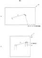
操作装置1は、例えば、図1(a)に示すように、運転席と助手席の間に位置するフロアコンソール10に配置され、車両に搭載された電子機器83を離れた位置で操作する遠隔操作装置である。この操作装置1は、例えば、運転席と助手席の斜め前方に配置される表示装置82に表示されたカーソルを移動させたり、アイコンを選択してドラッグアンドドロップを行ったり、地図画像やページのスクロールを行ったりできるように構成されている。 As shown in FIG. 1A, the operating device 1 is arranged on the floor console 10 located between the driver's seat and the passenger seat, and remotely operates the
電子機器83は、一例として、ナビゲーション装置、空調装置及び音楽再生装置などである。表示装置82は、電子機器83の表示部として機能する。なお表示装置82は、速度計などが配置されるメータパネル内に配置された表示装置であっても良いし、メータパネルに速度計などを表示する表示装置として構成されても良い。 The
操作装置1は、例えば、図1(a)及び図1(b)に示すように、操作面20に対するなぞり操作を検出するタッチパッド2と、タッチパッド2の近傍に設けられ、操作を受け付けると共に操作指の接触を検出する操作部4と、操作部4に対する接触が検出された場合、接触が検出されない場合と比べて、表示装置82に表示された操作対象の移動距離に対するなぞり操作の距離の比であるCD比を高くする制御部6と、を備えて概略構成されている。 As shown in FIGS. 1 (a) and 1 (b), for example, the operation device 1 is provided with a
本実施の形態の表示装置82に表示された操作対象は、一例として、表示装置82に表示される後述するカーソル821である。 The operation target displayed on the
操作装置1は、例えば、図1(a)に示すように、タッチパッド2を操作する際に操作者の手9が置かれるパームレスト86を備えている。操作装置1の操作部4は、操作者がパームレスト86に手9を置いた状態で操作可能な位置に配置される。このパームレスト86は、例えば、手が載せ易い丸みを帯びた形状を有している。 The operating device 1 includes, for example, as shown in FIG. 1A, a
操作装置1は、例えば、図2(a)に示すように、車両通信システム80に接続されている。この車両通信システム80は、車両LAN(Local Area Network)84を介して車両制御部81、表示装置82及び電子機器83などが接続されている。この車両LAN84は、例えば、有線及び無線によって相互に信号や情報などの交換を可能とするCAN(Controller Area Network)やLIN(Local Interconnect Network)といった車両用ネットワークである。この車両制御部81は、CPU(Central Processing Unit)、RAM(Random Access Memory)及びROM(Read Only Memory)などから構成されたマイクロコンピュータである。 The operating device 1 is connected to the vehicle communication system 80, for example, as shown in FIG. 2A. The vehicle communication system 80 is connected to a
(タッチパッド2の構成)
タッチパッド2は、例えば、操作者の体の一部(例えば、操作指)や専用のペンで操作面20に触れることにより、触れた操作面20上の位置(検出点)を検出するものである。操作者は、例えば、操作面20に操作を行うことにより、接続された電子機器83の操作を行うことが可能となる。タッチパッド2としては、例えば、抵抗膜方式、赤外線方式、静電容量方式などのタッチパッドを用いることが可能である。本実施の形態のタッチパッド2は、一例として、静電容量方式のタッチパッドである。(Structure of touchpad 2)
The
このタッチパッド2は、例えば、図1(a)に示すように、フロアコンソール10に操作面20が露出するように配置されている。 The
そしてタッチパッド2は、例えば、操作面20の下方に絶縁を保ちながら交差する複数の駆動電極と複数の検出電極を有している。タッチパッド2は、この複数の駆動電極と複数の検出電極の全ての組み合わせを走査して組み合わせごとの静電容量を読み出し、予め定められたしきい値以上の静電容量に基づいて検出対象が検出された後述する検出点910を算出する。この検出点910の算出は、例えば、加重平均を用いて行われる。 The
そしてタッチパッド2は、走査するたびに検出点910の座標を算出して周期的に検出情報S1を生成して制御部6に出力する。なお検出点910の座標は、例えば、操作面20に設定されたXY座標系における座標である。このXY座標は、運転席に着座する操作者から見て、左上が原点であり、横軸(車両の左右方向)がX軸、縦軸(車両の前後方向)がY軸である。なおタッチパッド2は、例えば、相対座標系のタッチパッドである。Then, each time the
(操作部4の構成)
操作部4は、例えば、図1(a)に示すように、パームレスト86の近傍に配置されている。操作部4は、運転席に着座する操作者の手9(左手)で操作し易いように、親指である操作指90の位置に対応して配置されている。以下では、一例として、操作部4を操作する操作指(親指)を操作指90とし、タッチパッド2を操作する操作指(一例として人差指であるが他の指でも良い)を操作指91とする。(Structure of operation unit 4)
The operation unit 4 is arranged in the vicinity of the
この操作部4は、例えば、操作面20に対して傾いて回転するホイールとして構成されると共に操作指90の接触を検出するように構成されている。この接触の検出は、例えば、ホイールに設けられたタッチセンサによって行われる。そして操作部4は、接触の有無と操作量に応じた接触操作情報S2を生成して制御部6に出力する。この操作量は、例えば、ホイールの回転量である。なお操作部4は、回転操作と共にプッシュ操作可能に構成されても良い。The operation unit 4 is configured as, for example, a wheel that rotates at an angle with respect to the
操作部4は、例えば、表示装置に表示されたメニュー項目のスクロールや設定値の変更などに用いられる。なお変形例として操作部4は、ホイールに限定されず、スライダー、静電方式のタッチセンサ、機械式プッシュスイッチなどであっても良い。 The operation unit 4 is used, for example, for scrolling menu items displayed on the display device and changing set values. As a modification, the operation unit 4 is not limited to the wheel, and may be a slider, an electrostatic touch sensor, a mechanical push switch, or the like.
操作者は、例えば、タッチパッド2と操作部4の操作を連続的に組み合わせることにより、カーソル821の移動と画像のスクロールを組み合わせて行うことができる。 For example, the operator can continuously move the
(制御部6の構成)
図3(a)及び図3(b)は、第1の実施の形態に係る操作装置が制御する、操作部に接触がない場合のCD比の一例を説明するための概略図である。図4(a)及び図4(b)は、第1の実施の形態に係る操作装置が制御する、操作部に接触がある場合のCD比の一例を説明するための概略図である。(Structure of control unit 6)
3 (a) and 3 (b) are schematic views for explaining an example of the CD ratio in the case where there is no contact with the operation unit, which is controlled by the operation device according to the first embodiment. 4 (a) and 4 (b) are schematic views for explaining an example of the CD ratio when there is contact with the operation unit, which is controlled by the operation device according to the first embodiment.
制御部6は、例えば、記憶されたプログラムに従って、取得したデータに演算、加工などを行うCPU、半導体メモリであるRAM及びROMなどから構成されるマイクロコンピュータである。このROMには、例えば、制御部6が動作するためのプログラムと、CD比情報60と、が格納されている。RAMは、例えば、一時的に演算結果などを格納する記憶領域として用いられる。また制御部6は、その内部にクロック信号を生成する手段を有し、このクロック信号に基づいて動作を行う。 The
CD比情報60は、例えば、図3(a)~図4(b)に示すカーソル821の移動距離に対するなぞり操作の距離の比に関する情報である。このCD比情報60には、少なくとも操作部4に対する接触がない場合の基準値のCD比、及び接触がある場合のCD比に関する情報が含まれている。このCD比は、例えば、数値として記憶されても良いし、関数として記憶されていても良い。なお図3(a)及び図3(b)のCD比は、CD比の基準値であるD/d1である。また図4(a)及び図4(b)のCD比は、CD比の基準値から変更されたD/d2である。The CD ratio information 60 is, for example, information regarding the ratio of the distance of the tracing operation to the moving distance of the
例えば、図1(a)に示すように、操作者が操作部4に操作指90を接触させて操作指91によって操作面20に対してなぞり操作を行う場合、操作部4から操作指90が離れないようになぞり操作を行うことから操作指91の可動範囲が限定される。つまり操作者は、操作部4に操作指90を接触させた状態で、操作指91によって操作面20の全域を操作することは困難である。 For example, as shown in FIG. 1A, when the operator brings the operation finger 90 into contact with the operation unit 4 and traces the
この操作指91の可動範囲は、一例として、図2(b)の紙面右下に操作部4が位置する場合、簡易的に近領域20a、中領域20b及び遠領域20cなどに分けられる。例えば、操作者が操作指90を操作部4に接触させたまま操作面20に対してなぞり操作を行う場合、可動範囲が近領域20aや、近領域20a及び中領域20bに限定され易い。なお操作指91の可動範囲は、操作部4に接触する操作指90を中心とした扇状の範囲に近いので、近領域20a、中領域20b及び遠領域20cを、円弧を含む領域としている。 As an example, when the operation unit 4 is located at the lower right of the paper surface of FIG. 2B, the movable range of the
従って操作者は、例えば、操作指90を操作部4に接触させた状態でカーソル821を目的の位置まで移動させる長い距離のなぞり操作が困難となる。図3(a)及び図3(b)は、操作指90が操作部4に接触していない場合のCD比の例であるが、例えば、接触した状態でこのCD比が適用された場合、カーソル821を目的の位置まで移動させる移動距離Dが長いので、なぞり操作の距離d1が長くなって操作性が良くない。Therefore, for example, it is difficult for the operator to perform a long-distance tracing operation of moving the
そこで制御部6は、操作部4に操作指90が接触している場合、操作指91の可動範囲が、接触していない場合と比べて狭いので、接触していない場合よりもCD比を高くするように構成されている。 Therefore, when the operating finger 90 is in contact with the operating unit 4, the
具体的には、操作指90が操作部4に接触していない場合は、例えば、図3(a)及び図3(b)に示すように、CD比がD/d1であるので、カーソル821を移動距離Dだけ移動させるためのなぞり操作の距離は、d1である。一方操作指90が操作部4に接触している場合は、例えば、図4(a)及び図4(b)に示すように、CD比が高くされるので、カーソル821を移動距離Dだけ移動させるためのなぞり操作の距離は、d1より短いd2となる。Specifically, when the operation finger 90 is not in contact with the operation unit 4, for example, as shown in FIGS. 3 (a) and 3 (b), the CD ratio is D / d1 , so that the cursorThe tracing operation distance for moving the 821 by the moving distance D is d1. On the other hand, when the operation finger 90 is in contact with the operation unit 4, for example, as shown in FIGS. 4A and 4B, the CD ratio is increased, so that the
なおCD比は、表示装置82の表示画面820の大きさ、操作面20の大きさなどに依存して最適な比とされる。CD比は、一例として、表示画面820と操作面20の面積の差が極端に大きくない場合(一例として3倍以下)、およそ0.1~0.3である。 The CD ratio is an optimum ratio depending on the size of the
制御部6は、タッチパッド2から取得する検出情報S1、及び操作部4から出力される接触操作情報S2に基づいて電子機器83に出力する操作情報S3を生成する。この操作情報S3は、少なくとも検出点910の座標の情報や操作部4の操作量の情報を含んでいる。The control unit6 generates operation information S3 to beoutput to the
ここでCD比を変更する場合、少なくとも次の2通りの方法が考えられる。1つは、操作装置1がなぞり操作の距離の情報含む操作情報S3を生成する場合、予め定められた正の定数を算出した距離に乗算してCD比を高くする方法である。この定数は、CD比情報60に含まれる。Here, when changing the CD ratio, at least the following two methods can be considered. One is a method of increasing the CD ratio by multiplying a predetermined positive constant by a calculated distance when the operation device1 generates operation information S3 including information on the distance of the tracing operation. This constant is included in the CD ratio information 60.
もう1つは、操作装置1が検出点910の座標又はなぞり操作の距離を含む操作情報S3を生成する場合、さらに電子機器83側でCD比を変更するように指示する指示情報を含んだ操作情報S3を出力し、電子機器83側でCD比を高くする方法である。この指示信号は、CD比情報60に基づいて生成される。本実施の形態の制御部6は、例えば、なぞり操作の距離に予め定められた正の定数を乗算して操作情報S3を生成するように構成されている。The other includes instruction information instructing the
ここで変形例として制御部6は、操作部4に対する接触が検出された場合、操作部4に接触していない場合と比べて、操作面20になされたフリック操作の検出感度を高くするように構成されても良い。この変形例における操作装置1は、操作部4に操作指90が接触して操作指91の可動範囲が狭く、フリック操作がし難い場合でも、検出感度を高めることにより、操作部4に接触した状態、又は操作部4を操作しながら行われたフリック操作の検出精度を向上させることができる。 Here, as a modification, the
また他の変形例として制御部6は、タッチパッド2及び操作部4の少なくとも一方になされた操作によって、操作部4に対する接触が検出された場合のCD比、及び接触が検出されなかった場合のCD比の少なくとも一方を操作者によって設定されても良い。制御部6は、一例として、操作者が操作部4に操作指90を接触させた状態で操作面20に対してタップ操作を行った場合、少なくとも一方のCD比を設定できる画面を表示装置82に表示させるように構成される。この変形例の操作装置1は、少なくとも一方のCD比を設定できるので、設定できない場合と比べて、CD比が合わないことに起因する操作者の違和感を抑制することができる。 As another modification, the
以下に本実施の形態の操作装置1のCD比を変更する動作の一例について図5のフローチャートに従って説明する。 An example of the operation of changing the CD ratio of the operation device 1 of the present embodiment will be described below with reference to the flowchart of FIG.
(動作)
操作装置1の制御部6は、電源が投入されると、タッチパッド2から検出情報S1を取得すると共に操作部4から接触操作情報S2を取得する。制御部6は、接触操作情報S2に基づいて操作指90の接触が検出されると(Step1:Yes)、CD比情報60に基づいてCD比を基準値から変更した状態で(Step2)、タッチパッド2に操作がなされるか監視する。なお制御部6は、接触が検出されなくなると、CD比を基準値に変更する。(motion)
When the power is turned on, the
ここで制御部6は、接触が検出されない場合(Step1:No)、CD比を基準値に維持した状態で(Step3)、タッチパッド2に操作がなされるか監視する。 Here, when the contact is not detected (Step 1: No), the
(第1の実施の形態の効果)
本実施の形態に係る操作装置1は、操作性を向上させることができる。具体的には、操作装置1は、操作部4に対する接触が検出されると、検出されない場合と比べて、CD比を高くしてなぞり操作の距離が小さくても操作対象の移動距離を大きくすることができるので、操作指の可動範囲が限定された状態であっても操作性を向上させることができる。(Effect of the first embodiment)
The operation device 1 according to the present embodiment can improve the operability. Specifically, when the operation device 1 detects contact with the operation unit 4, the CD ratio is increased and the moving distance of the operation target is increased even if the tracing operation distance is small, as compared with the case where the contact is not detected. Therefore, the operability can be improved even when the movable range of the operating finger is limited.
操作装置1は、CD比を高くすることにより、タッチパッド2の操作と操作部4の操作を両立させることができる。そして操作装置1は、タッチパッド2と操作部4を連続的に組み合わせた操作を行うことができるので、電子機器83の操作の種類が増加する。 By increasing the CD ratio, the operation device 1 can make the operation of the
[第2の実施の形態]
第2の実施の形態は、タッチパッドで検出された操作指と操作部で検出された操作指の距離に基づいてCD比を変更する点で他の実施の形態と異なっている。[Second Embodiment]
The second embodiment is different from the other embodiments in that the CD ratio is changed based on the distance between the operating finger detected by the touch pad and the operating finger detected by the operating unit.
図6(a)及び図6(b)は、第2の実施の形態に係る操作装置の操作指間の距離が短い場合のCD比の一例について説明するための概略図である。また図7(a)及び図7(b)は、第2の実施の形態に係る操作装置の操作指間の距離が長い場合のCD比の一例について説明するための概略図である。図6(b)及び図7(b)は、上面から見たタッチパッド2と操作部4を模式的に図示している。この図6(b)及び図7(b)の紙面の法線方向がXY座標と直交するZ軸となる。 6 (a) and 6 (b) are schematic views for explaining an example of the CD ratio when the distance between the operating fingers of the operating device according to the second embodiment is short. Further, FIGS. 7 (a) and 7 (b) are schematic views for explaining an example of the CD ratio when the distance between the operating fingers of the operating device according to the second embodiment is long. 6 (b) and 7 (b) schematically show the
なお以下に記載する実施の形態において、第1の実施の形態と同じ機能及び構成を有する部分は、第1の実施の形態と同じ符号を付し、その説明は省略するものとする。また本実施の形態では、一例として、操作指91によってタッチパッド2を操作すると共に操作指90によって操作部4を操作するとしているがこれに限定されない。 In the embodiments described below, the parts having the same functions and configurations as those of the first embodiment are designated by the same reference numerals as those of the first embodiment, and the description thereof will be omitted. Further, in the present embodiment, as an example, the
操作装置1は、例えば、図6(b)及び図7(b)に示すように、操作部4と共にタッチパッド2を操作できるように、操作面20が含まれる平面に設定されたXY座標系のY軸方向に操作面20と操作部4とが並んで配置されている。言い換えるなら操作装置1は、操作者の手9が置かれるパームレスト86の近傍にタッチパッド2が配置され、このパームレスト86の側部に操作部4が配置され、操作部4に操作指90を接触させた状態でタッチパッド2の操作が可能となるようにされている。 As shown in FIGS. 6 (b) and 7 (b), for example, the operation device 1 is set in an XY coordinate system set on a plane including the
このXY座標系は、例えば、図6(b)及び図7(b)の紙面において操作面20の左上を原点とし、左から右にX軸、上から下にY軸が設定されている。操作面20上の検出点910は、このXY座標系の座標を有する。また操作部4の検出点40は、操作部4が検出した操作指90の検出点40をXY座標系に投影し、この投影したXY座標系の座標を与えられる。なお操作部4の検出点40は、例えば、操作指90が接触している点でも良いし、平行移動したX軸と操作部4の交点としても良い。 In this XY coordinate system, for example, the upper left of the
制御部6は、タッチパッド2において検出された操作指91の検出点910のY座標と、操作部4によって検出された操作指90の検出点40のY座標と、の差を距離Lとし、距離Lに基づいてCD比を変更する。後述するように制御部6は、距離Lが短い方が長い方と比べてCD比を高く(早く)する。また制御部6は、距離が変わる度にCD比を変更する。 The
本実施の形態のCD比情報60は、距離LとCD比を関連付けた情報を有している。なおCD比は、距離Lの関数としても良い。 The CD ratio information 60 of the present embodiment has information relating the distance L and the CD ratio. The CD ratio may be a function of the distance L.
例えば、図6(a)及び図6(b)に示すように、パームレスト86の近くにおいて、操作部4に接触した状態でタッチパッド2が操作された場合、手9がすぼんだ状態での操作になるので、操作指91の可動域が小さくなる。そこで制御部6は、図6(b)に示す距離LaとCD比情報60とに基づいて距離Laに適したCD比(Da/da)によって、なぞり操作の距離daにより遠い際よりも長く(早く)、カーソル821を移動距離Da移動させる。For example, as shown in FIGS. 6 (a) and 6 (b), when the
また、例えば、図7(a)及び図7(b)に示すように、パームレスト86から離れて、操作部4に接触した状態でタッチパッド2が操作された場合、手9が広がった状態での操作になるので、操作指91の可動域が大きくなる。そこで制御部6は、図7(b)に示す距離LbとCD比情報60とに基づいて距離Lbに適したCD比(Db/da:Db/da<Da/da)によって、なぞり操作の距離daが近い際と同じでも、カーソル821を移動距離Daより短い(遅い)移動距離Db移動させる。Further, for example, as shown in FIGS. 7 (a) and 7 (b), when the
つまりカーソル821は、なぞり操作の距離が同じであっても、距離Lが長い場合、移動距離Dが短く(CD比が遅く)なり、距離Lが短い場合、移動距離Dが長く(CD比が早く)なる。 That is, even if the distance of the tracing operation is the same, the
以下に本実施の形態の操作装置1のCD比を変更する動作の一例について図8のフローチャートに従って説明する。 An example of the operation of changing the CD ratio of the operation device 1 of the present embodiment will be described below with reference to the flowchart of FIG.
(動作)
操作装置1の制御部6は、電源が投入されると、タッチパッド2から検出情報S1を取得すると共に操作部4から接触操作情報S2を取得する。制御部6は、接触操作情報S2に基づいて操作指90の接触が検出されると(Step10:Yes)、操作指91の検出点910などから距離Lを算出する(Step11)。(motion)
When the power is turned on, the
次に制御部6は、算出した距離LとCD比情報60に基づいてCD比を基準値から変更する(Step12)。このCD比の変更は、距離Lが変わる度に、つまり実質的にリアルタイムで行われる。 Next, the
ここで制御部6は、接触が検出されない場合(Step11:No)、CD比を基準値に維持した状態で(Step13)、タッチパッド2に操作がなされるか監視する。 Here, when the contact is not detected (Step 11: No), the
(第2の実施の形態の効果)
本実施の形態の操作装置1は、手がすぼんだ状態でも広がった状態でも適切なCD比を設定し、CD比が固定の場合と比べて、操作性を向上させることができる。(Effect of the second embodiment)
The operation device 1 of the present embodiment sets an appropriate CD ratio regardless of whether the hand is in a depressed state or in an expanded state, and can improve operability as compared with the case where the CD ratio is fixed.
以上、本発明のいくつかの実施の形態及び変形例を説明したが、これらの実施の形態及び変形例は、一例に過ぎず、特許請求の範囲に係る発明を限定するものではない。これら新規な実施の形態及び変形例は、その他の様々な形態で実施されることが可能であり、本発明の要旨を逸脱しない範囲で、種々の省略、置き換え、変更などを行うことができる。また、これら実施の形態及び変形例の中で説明した特徴の組合せの全てが発明の課題を解決するための手段に必須であるとは限らない。さらに、これら実施の形態及び変形例は、発明の範囲及び要旨に含まれると共に、特許請求の範囲に記載された発明とその均等の範囲に含まれる。 Although some embodiments and modifications of the present invention have been described above, these embodiments and modifications are merely examples and do not limit the invention according to the claims. These novel embodiments and modifications can be implemented in various other embodiments, and various omissions, replacements, changes, etc. can be made without departing from the gist of the present invention. Moreover, not all of the combinations of features described in these embodiments and modifications are essential for the means for solving the problems of the invention. Further, these embodiments and modifications are included in the scope and gist of the invention, and are included in the scope of the invention described in the claims and the equivalent scope thereof.
1…操作装置、2…タッチパッド、4…操作部、6…制御部、9…手、10…フロアコンソール、20…操作面、20a…近領域、20b…中領域、20c…遠領域、40…検出点、60…CD比情報、80…車両通信システム、81…車両制御部、82…表示装置、83…電子機器、84…車両LAN、86…パームレスト、90,91…操作指、820…表示画面、821…カーソル、910…検出点1 ... Operation device, 2 ... Touch pad, 4 ... Operation unit, 6 ... Control unit, 9 ... Hand, 10 ... Floor console, 20 ... Operation surface, 20a ... Near area, 20b ... Medium area, 20c ... Far area, 40 ... Detection point, 60 ... CD ratio information, 80 ... Vehicle communication system, 81 ... Vehicle control unit, 82 ... Display device, 83 ... Electronic device, 84 ... Vehicle LAN, 86 ... Palm rest, 90, 91 ... Operation finger, 820 ... Display screen, 821 ... cursor, 910 ... detection point
Claims (6)
Translated fromJapanese前記タッチパッドの近傍に設けられ、表示装置に表示された操作対象を操作するための操作(前記操作対象の移動速度を変化させる操作を除く)を受け付けると共に操作指の接触を検出する操作部と、
前記操作部に対する接触が検出された場合、接触が検出されない場合と比べて、前記タッチパッドの操作対象の移動距離に対する前記なぞり操作の距離の比であるCD比を高くする制御部と、
を備えた操作装置。A touch pad that detects the tracing operation on the operation surface made to operate the operation target displayed on the display device, and
An operation unit provided near the touch pad that accepts operations for operating the operation target displayed on the display device(excluding operations that change the moving speed of the operation target) and detects contact with the operating finger. ,
When a contact with the operation unit is detected, a control unit for increasing the CD ratio, which is the ratio of the distance of the tracing operation to the moving distance of the operation target of the touch pad, as compared with the case where the contact is not detected.
An operating device equipped with.
請求項1に記載の操作装置。When the control unit detects contact with the operation unit, the control unit increases the detection sensitivity of the flick operation performed on the operation surface as compared with the case where the operation unit is not in contact with the operation unit.
The operating device according to claim 1.
請求項1又は2に記載の操作装置。In the control unit, at least one of the CD ratio when contact with the operation unit is detected and the CD ratio when no contact is detected by the operation performed by at least one of the touch pad and the operation unit is Can be set by the operator,
The operating device according to claim 1 or 2.
前記制御部は、前記タッチパッドにおいて検出された操作指の検出点のY座標と、前記操作部によって検出された操作指の検出点のY座標と、の差を距離とし、前記距離に基づいてCD比を変更する、
請求項1又は2に記載の操作装置。The operation surface and the operation unit are arranged side by side in the Y-axis direction of the XY coordinate system set on the plane including the operation surface so that the touch pad can be operated together with the operation unit.
The control unit uses the difference between the Y coordinate of the detection point of the operation finger detected by the touch pad and the Y coordinate of the detection point of the operation finger detected by the operation unit as a distance, and is based on the distance. Change the CD ratio,
The operating device according to claim 1 or 2.
請求項4に記載の操作装置。The control unit has a higher CD ratio when the distance is shorter than when the distance is longer.
The operating device according to claim 4.
請求項4又は5に記載の操作装置。The control unit changes the CD ratio each time the distance changes.
The operating device according to claim 4 or 5.
Applications Claiming Priority (2)
| Application Number | Priority Date | Filing Date | Title |
|---|---|---|---|
| JP2017031908 | 2017-02-23 | ||
| JP2017031908 | 2017-02-23 |
Publications (2)
| Publication Number | Publication Date |
|---|---|
| JP2018136906A JP2018136906A (en) | 2018-08-30 |
| JP7001368B2true JP7001368B2 (en) | 2022-01-19 |
Family
ID=63365646
Family Applications (1)
| Application Number | Title | Priority Date | Filing Date |
|---|---|---|---|
| JP2017112402AExpired - Fee RelatedJP7001368B2 (en) | 2017-02-23 | 2017-06-07 | Operation device |
Country Status (1)
| Country | Link |
|---|---|
| JP (1) | JP7001368B2 (en) |
Citations (2)
| Publication number | Priority date | Publication date | Assignee | Title |
|---|---|---|---|---|
| US20150049020A1 (en) | 2013-08-19 | 2015-02-19 | Lenovo (Singapore) Pte. Ltd. | Devices and methods for electronic pointing device acceleration |
| WO2016114269A1 (en) | 2015-01-15 | 2016-07-21 | シャープ株式会社 | Information processing device and control method therefor |
- 2017
- 2017-06-07JPJP2017112402Apatent/JP7001368B2/ennot_activeExpired - Fee Related
Patent Citations (2)
| Publication number | Priority date | Publication date | Assignee | Title |
|---|---|---|---|---|
| US20150049020A1 (en) | 2013-08-19 | 2015-02-19 | Lenovo (Singapore) Pte. Ltd. | Devices and methods for electronic pointing device acceleration |
| WO2016114269A1 (en) | 2015-01-15 | 2016-07-21 | シャープ株式会社 | Information processing device and control method therefor |
Also Published As
| Publication number | Publication date |
|---|---|
| JP2018136906A (en) | 2018-08-30 |
Similar Documents
| Publication | Publication Date | Title |
|---|---|---|
| US8570283B2 (en) | Information processing apparatus, information processing method, and program | |
| US9511669B2 (en) | Vehicular input device and vehicular cockpit module | |
| JP5784061B2 (en) | Input device, input method, and input program | |
| JP2019175449A (en) | Information processing apparatus, information processing system, movable body, information processing method, and program | |
| JP6119679B2 (en) | Vehicle input device | |
| JP6035828B2 (en) | Display operation device and display system | |
| JP2013097513A (en) | Input device for vehicle | |
| JP2008009759A (en) | Touch panel device | |
| JP5003377B2 (en) | Mark alignment method for electronic devices | |
| CN108108042B (en) | Display device for vehicle and control method thereof | |
| JP2015170282A (en) | Operation device for vehicle | |
| JP7245167B2 (en) | Smart devices with displays that allow simultaneous multifunctional operation of displayed information and/or data | |
| US20130201126A1 (en) | Input device | |
| JP2018195134A (en) | On-vehicle information processing system | |
| JP7001368B2 (en) | Operation device | |
| US20180232115A1 (en) | In-vehicle input device and in-vehicle input device control method | |
| JP2017068291A (en) | Input method and input device | |
| JP2008204375A (en) | Panel input device, stylus pen for panel input, panel input system, and panel input processing program | |
| JP2018124811A (en) | Operation device | |
| JP2019032886A (en) | Display control device, display control method, and display control device program | |
| JP2018032123A (en) | Operation input device | |
| JP2018032122A (en) | Display operation device | |
| JP2025149316A (en) | User interface device and display method | |
| KR101681994B1 (en) | Controlling apparatus using touch input, vehicle comprising the same | |
| JP2017004405A (en) | Operation device |
Legal Events
| Date | Code | Title | Description |
|---|---|---|---|
| A621 | Written request for application examination | Free format text:JAPANESE INTERMEDIATE CODE: A621 Effective date:20191120 | |
| A977 | Report on retrieval | Free format text:JAPANESE INTERMEDIATE CODE: A971007 Effective date:20200828 | |
| A131 | Notification of reasons for refusal | Free format text:JAPANESE INTERMEDIATE CODE: A131 Effective date:20200915 | |
| A521 | Request for written amendment filed | Free format text:JAPANESE INTERMEDIATE CODE: A523 Effective date:20201104 | |
| A02 | Decision of refusal | Free format text:JAPANESE INTERMEDIATE CODE: A02 Effective date:20201117 | |
| A521 | Request for written amendment filed | Free format text:JAPANESE INTERMEDIATE CODE: A523 Effective date:20210119 | |
| C60 | Trial request (containing other claim documents, opposition documents) | Free format text:JAPANESE INTERMEDIATE CODE: C60 Effective date:20210119 | |
| A911 | Transfer to examiner for re-examination before appeal (zenchi) | Free format text:JAPANESE INTERMEDIATE CODE: A911 Effective date:20210127 | |
| C21 | Notice of transfer of a case for reconsideration by examiners before appeal proceedings | Free format text:JAPANESE INTERMEDIATE CODE: C21 Effective date:20210202 | |
| A912 | Re-examination (zenchi) completed and case transferred to appeal board | Free format text:JAPANESE INTERMEDIATE CODE: A912 Effective date:20210326 | |
| C211 | Notice of termination of reconsideration by examiners before appeal proceedings | Free format text:JAPANESE INTERMEDIATE CODE: C211 Effective date:20210330 | |
| C22 | Notice of designation (change) of administrative judge | Free format text:JAPANESE INTERMEDIATE CODE: C22 Effective date:20210720 | |
| C22 | Notice of designation (change) of administrative judge | Free format text:JAPANESE INTERMEDIATE CODE: C22 Effective date:20210921 | |
| C23 | Notice of termination of proceedings | Free format text:JAPANESE INTERMEDIATE CODE: C23 Effective date:20211102 | |
| C03 | Trial/appeal decision taken | Free format text:JAPANESE INTERMEDIATE CODE: C03 Effective date:20211207 | |
| C30A | Notification sent | Free format text:JAPANESE INTERMEDIATE CODE: C3012 Effective date:20211207 | |
| A61 | First payment of annual fees (during grant procedure) | Free format text:JAPANESE INTERMEDIATE CODE: A61 Effective date:20211224 | |
| R150 | Certificate of patent or registration of utility model | Ref document number:7001368 Country of ref document:JP Free format text:JAPANESE INTERMEDIATE CODE: R150 | |
| LAPS | Cancellation because of no payment of annual fees |