JP7001269B2 - Massage device - Google Patents
Massage deviceDownload PDFInfo
- Publication number
- JP7001269B2 JP7001269B2JP2018153594AJP2018153594AJP7001269B2JP 7001269 B2JP7001269 B2JP 7001269B2JP 2018153594 AJP2018153594 AJP 2018153594AJP 2018153594 AJP2018153594 AJP 2018153594AJP 7001269 B2JP7001269 B2JP 7001269B2
- Authority
- JP
- Japan
- Prior art keywords
- arm member
- treatment
- massage
- load
- massage device
- Prior art date
- Legal status (The legal status is an assumption and is not a legal conclusion. Google has not performed a legal analysis and makes no representation as to the accuracy of the status listed.)
- Active
Links
- 230000005489elastic deformationEffects0.000claimsdescription3
- 230000003028elevating effectEffects0.000description12
- 238000010079rubber tappingMethods0.000description10
- 230000001105regulatory effectEffects0.000description9
- 238000004898kneadingMethods0.000description7
- 230000033001locomotionEffects0.000description4
- 230000005540biological transmissionEffects0.000description3
- 239000002184metalSubstances0.000description2
- 230000007935neutral effectEffects0.000description2
- 230000002093peripheral effectEffects0.000description2
- 210000000689upper legAnatomy0.000description2
- 238000005452bendingMethods0.000description1
- 210000001217buttockAnatomy0.000description1
- 210000001624hipAnatomy0.000description1
Images


Classifications
- A—HUMAN NECESSITIES
- A61—MEDICAL OR VETERINARY SCIENCE; HYGIENE
- A61H—PHYSICAL THERAPY APPARATUS, e.g. DEVICES FOR LOCATING OR STIMULATING REFLEX POINTS IN THE BODY; ARTIFICIAL RESPIRATION; MASSAGE; BATHING DEVICES FOR SPECIAL THERAPEUTIC OR HYGIENIC PURPOSES OR SPECIFIC PARTS OF THE BODY
- A61H7/00—Devices for suction-kneading massage; Devices for massaging the skin by rubbing or brushing not otherwise provided for
- A61H7/007—Kneading
- A—HUMAN NECESSITIES
- A61—MEDICAL OR VETERINARY SCIENCE; HYGIENE
- A61H—PHYSICAL THERAPY APPARATUS, e.g. DEVICES FOR LOCATING OR STIMULATING REFLEX POINTS IN THE BODY; ARTIFICIAL RESPIRATION; MASSAGE; BATHING DEVICES FOR SPECIAL THERAPEUTIC OR HYGIENIC PURPOSES OR SPECIFIC PARTS OF THE BODY
- A61H23/00—Percussion or vibration massage, e.g. using supersonic vibration; Suction-vibration massage; Massage with moving diaphragms
- A61H23/006—Percussion or tapping massage
- A—HUMAN NECESSITIES
- A61—MEDICAL OR VETERINARY SCIENCE; HYGIENE
- A61H—PHYSICAL THERAPY APPARATUS, e.g. DEVICES FOR LOCATING OR STIMULATING REFLEX POINTS IN THE BODY; ARTIFICIAL RESPIRATION; MASSAGE; BATHING DEVICES FOR SPECIAL THERAPEUTIC OR HYGIENIC PURPOSES OR SPECIFIC PARTS OF THE BODY
- A61H7/00—Devices for suction-kneading massage; Devices for massaging the skin by rubbing or brushing not otherwise provided for
- A61H7/007—Kneading
- A61H2007/009—Kneading having massage elements rotating on parallel output axis
- A—HUMAN NECESSITIES
- A61—MEDICAL OR VETERINARY SCIENCE; HYGIENE
- A61H—PHYSICAL THERAPY APPARATUS, e.g. DEVICES FOR LOCATING OR STIMULATING REFLEX POINTS IN THE BODY; ARTIFICIAL RESPIRATION; MASSAGE; BATHING DEVICES FOR SPECIAL THERAPEUTIC OR HYGIENIC PURPOSES OR SPECIFIC PARTS OF THE BODY
- A61H2201/00—Characteristics of apparatus not provided for in the preceding codes
- A61H2201/01—Constructive details
- A61H2201/0119—Support for the device
- A—HUMAN NECESSITIES
- A61—MEDICAL OR VETERINARY SCIENCE; HYGIENE
- A61H—PHYSICAL THERAPY APPARATUS, e.g. DEVICES FOR LOCATING OR STIMULATING REFLEX POINTS IN THE BODY; ARTIFICIAL RESPIRATION; MASSAGE; BATHING DEVICES FOR SPECIAL THERAPEUTIC OR HYGIENIC PURPOSES OR SPECIFIC PARTS OF THE BODY
- A61H2201/00—Characteristics of apparatus not provided for in the preceding codes
- A61H2201/01—Constructive details
- A61H2201/0165—Damping, vibration related features
- A—HUMAN NECESSITIES
- A61—MEDICAL OR VETERINARY SCIENCE; HYGIENE
- A61H—PHYSICAL THERAPY APPARATUS, e.g. DEVICES FOR LOCATING OR STIMULATING REFLEX POINTS IN THE BODY; ARTIFICIAL RESPIRATION; MASSAGE; BATHING DEVICES FOR SPECIAL THERAPEUTIC OR HYGIENIC PURPOSES OR SPECIFIC PARTS OF THE BODY
- A61H2201/00—Characteristics of apparatus not provided for in the preceding codes
- A61H2201/12—Driving means
- A61H2201/1207—Driving means with electric or magnetic drive
- A61H2201/1215—Rotary drive
- A—HUMAN NECESSITIES
- A61—MEDICAL OR VETERINARY SCIENCE; HYGIENE
- A61H—PHYSICAL THERAPY APPARATUS, e.g. DEVICES FOR LOCATING OR STIMULATING REFLEX POINTS IN THE BODY; ARTIFICIAL RESPIRATION; MASSAGE; BATHING DEVICES FOR SPECIAL THERAPEUTIC OR HYGIENIC PURPOSES OR SPECIFIC PARTS OF THE BODY
- A61H2201/00—Characteristics of apparatus not provided for in the preceding codes
- A61H2201/14—Special force transmission means, i.e. between the driving means and the interface with the user
- A61H2201/1418—Cam
- A—HUMAN NECESSITIES
- A61—MEDICAL OR VETERINARY SCIENCE; HYGIENE
- A61H—PHYSICAL THERAPY APPARATUS, e.g. DEVICES FOR LOCATING OR STIMULATING REFLEX POINTS IN THE BODY; ARTIFICIAL RESPIRATION; MASSAGE; BATHING DEVICES FOR SPECIAL THERAPEUTIC OR HYGIENIC PURPOSES OR SPECIFIC PARTS OF THE BODY
- A61H2201/00—Characteristics of apparatus not provided for in the preceding codes
- A61H2201/16—Physical interface with patient
- A61H2201/1657—Movement of interface, i.e. force application means
- A61H2201/1671—Movement of interface, i.e. force application means rotational
- A—HUMAN NECESSITIES
- A61—MEDICAL OR VETERINARY SCIENCE; HYGIENE
- A61H—PHYSICAL THERAPY APPARATUS, e.g. DEVICES FOR LOCATING OR STIMULATING REFLEX POINTS IN THE BODY; ARTIFICIAL RESPIRATION; MASSAGE; BATHING DEVICES FOR SPECIAL THERAPEUTIC OR HYGIENIC PURPOSES OR SPECIFIC PARTS OF THE BODY
- A61H2201/00—Characteristics of apparatus not provided for in the preceding codes
- A61H2201/16—Physical interface with patient
- A61H2201/1657—Movement of interface, i.e. force application means
- A61H2201/1676—Pivoting
Landscapes
- Health & Medical Sciences (AREA)
- Life Sciences & Earth Sciences (AREA)
- Epidemiology (AREA)
- Pain & Pain Management (AREA)
- Physical Education & Sports Medicine (AREA)
- Rehabilitation Therapy (AREA)
- Animal Behavior & Ethology (AREA)
- General Health & Medical Sciences (AREA)
- Public Health (AREA)
- Veterinary Medicine (AREA)
- Dermatology (AREA)
- Massaging Devices (AREA)
- Percussion Or Vibration Massage (AREA)
Description
Translated fromJapanese本発明は、マッサージ装置に関するものである。 The present invention relates to a massage device.
従来より、使用者の施療部に対する施療子からの過負荷を軽減する負荷軽減機構を備えたマッサージ装置が開発されている。このマッサージ装置の負荷軽減機構は、施療子に対して付与された過大な負荷を分散させる機能も有し、マッサージ装置自体の破損等を軽減するような構造となっている。
かかる負荷軽減機構を備えたマッサージ装置としては、特許文献1のようなものが知られている。Conventionally, a massage device equipped with a load reducing mechanism for reducing an overload from a treatment child on a treatment unit of a user has been developed. The load reducing mechanism of this massage device also has a function of distributing an excessive load applied to the treatment child, and has a structure for reducing damage to the massage device itself.
As a massage device provided with such a load reducing mechanism, a massage device such as
例えば、特許文献1には、施療子駆動ユニット7のもみ用回転軸に、コイルバネよりなる施療子支持体を取り付け、さらに施療子支持体の自由端に施療子を取り付けたマッサージ機が開示されている。このような施療子支持体を設ければ、施療子に強い負荷がかかると、コイルバネよりなる施療子支持体が弾性変形して負荷を吸収するため、施療部に施療子から加わる負荷を軽減することができ、施療子の当たりがソフトなマッサージ装置を得ることができる。 For example,
ところで、特許文献1のマッサージ機に設けられる施療子支持体は、水平方向に軸心を向けるもみ用回転軸に対して、もみ用回転軸に上下方向に傾いて交差する軸回りを巻回するコイルバネを用いている。この特許文献1のコイルバネは前後方向だけでなく左右方向にも弾性変形するものとなっており、前後方向に沿った負荷だけでなく左右方向に沿った負荷をも吸収可能なものとなっている。 By the way, the treatment child support provided in the massage machine of
そのため、例えば、施療部に対して揉みマッサージを行う際に、施療子が左右方向に沿って揺動した場合にも、コイルバネが余計な弾性変形を起こして施療部に加わるマッサージ力を弱めてしまう可能性があり、満足できるマッサージを行えなくなる可能性がある。
例えば、揉みマッサージを行うマッサージ装置を例に挙げれば、左右のマッサージアームを互いに反対方向に向かって揺動させ、左右一対のマッサージアーム同士を互いに近接・離反させるようにして、マッサージアームの先端に設けられた左右の施療子の間に施療部を間欠的に挟んだり離したりして、施療部に対して揉みマッサージを行う構成となっている。それゆえ、施療子とアームアームの間に左右方向に弾性変形するバネを設けると、この施療子による施療部の挟み込みの力、言い換えれば揉みマッサージの強度(マッサージ力)も必要以上に軽減される結果となってしまう可能性があった。Therefore, for example, when the massager massages the treatment area, even if the treatment element swings in the left-right direction, the coil spring causes excessive elastic deformation and weakens the massage force applied to the treatment area. There is a possibility that you will not be able to get a satisfactory massage.
For example, taking a massage device that performs massage massage as an example, the left and right massage arms are swung in opposite directions so that the pair of left and right massage arms are brought close to each other and separated from each other, and are attached to the tip of the massage arm. The treatment section is intermittently sandwiched or separated between the left and right treatment sections provided, and the treatment section is massaged by kneading. Therefore, if a spring that elastically deforms in the left-right direction is provided between the treatment child and the arm, the force of the treatment child to pinch the treatment part, in other words, the strength of the kneading massage (massage force) is reduced more than necessary. There was a possibility that it would result.
本発明は、上述の問題に鑑みてなされたものであり、使用者の施療部が施療子に強く接した場合であっても、使用者の施療部に対して施療子から過大な負荷が加えられることを可及的に防止すると共に、好適なマッサージを付与可能とし、更には、施療子に対して付与された過大な負荷を分散させる機能を有し、マッサージ装置自体の破損等を軽減するような構造を備えたマッサージ装置を提供することを目的とする。 The present invention has been made in view of the above-mentioned problems, and even when the treatment unit of the user is in strong contact with the treatment unit, an excessive load is applied to the treatment unit of the user from the treatment unit. As much as possible, it is possible to give a suitable massage, and it also has a function to disperse the excessive load given to the treatment child, and reduce the damage of the massage device itself. It is an object of the present invention to provide a massage device having such a structure.
上記課題を解決するため、本発明のマッサージ装置は以下の技術的手段を講じている。
即ち、本発明のマッサージ装置は、使用者の施療部を施療する施療子と、前記施療子が先端に取り付けられたアーム部材と、を備えたマッサージ装置であって、前記アーム部材には、前記施療子からアーム部材側に加わる負荷を吸収する負荷軽減機構が設けられており、前記負荷軽減機構は、前後方向に沿った付勢力を利用して前記施療子への負荷を吸収する構成とされており、前記アーム部材は、第1のアーム部材と第2のアーム部材とを有し、前記第1のアーム部材は、回転駆動力を発生させる回転駆動軸に交差するように一方側に向かって伸びるものとされ、前記第2のアーム部材は、前記回転駆動軸に交差するように他方側に向かって伸びるものとされており、前記第1のアーム部材の先端には第1の施療子が設けられ、前記第2のアーム部材の先端には第2の施療子が設けられていて、
前記負荷軽減機構は、前記第1のアーム部材と第1の施療子との間に配備されて前記回転駆動軸に平行な軸心回りに付勢されたバネ部材と、前記アーム部材を回転駆動軸回りに揺動自在の支持する支持構造とを有していることを特徴とする。
好ましくは、前記負荷軽減機構は、前記第2のアーム部材の長手方向の一部に形成された薄肉部分を具備し、前記薄肉部分の弾性変形により当該第2のアーム部材を前後方向に撓ませることで、前後方向に沿った付勢力を発現させるように構成するとよい。In order to solve the above problems, the massage device of the present invention takes the following technical means.
That is, the massage device of the present invention is a massage device including a treatment element for treating a treatment unit of a user and an arm member to which the treatment element is attached to the tip, and the arm member includes the above-mentioned arm member. A load reduction mechanism for absorbing the load applied to the arm member side from the treatment child is provided, and the load reduction mechanism is configured to absorb the load on the treatment child by using the urging force along the front-rear direction.The arm member has a first arm member and a second arm member, and the first arm member faces one side so as to intersect a rotation drive shaft that generates a rotation drive force.The second arm member extends toward the other side so as to intersect the rotation drive shaft,and the tip of the first arm memberhas a first massager. Is provided, and a second treatment element is provided at the tip of the second arm member.
The load reducing mechanism is a spring member deployed between the first arm member and the first treatment element and urged around the axis parallel to the rotation drive axis, and the arm member is rotationally driven. It is characterizedby having a support structure that swings around the axis and supports it .
Preferably, the load reducing mechanism includes a thin-walled portion formed in a part of the second arm member in the longitudinal direction, and the second arm member is flexed in the front-rear direction by elastic deformation of the thin-walled portion. Therefore, it is preferable to configure it so as to generate an urging force along the front-back direction.
なお、好ましくは、前記支持構造により、第1の施療子におけるバネ部材の付勢力を第2の施療子に伝達するとよい。
なお、好ましくは、前記第1のアーム部材及び第2のアーム部材が配備されたマッサージ基盤体と、前記マッサージ基盤体を、所定の揺動角に亘って前記回転駆動軸回りに揺動可能に支持するフレーム体と、を備えているとよい。It is preferable that the support structure transmits the urging force of the spring member in the first treatment element to the second treatment element.
It should be noted that preferably, the massage base body to which the first arm member and the second arm member are deployed and the massage base body can be swung around the rotation drive axis over a predetermined swing angle. It is preferable to have a supporting frame body.
本発明のマッサージ装置によれば、使用者の施療部が施療子に強く接した場合であっても、使用者の施療部に対して施療子から過大な負荷が加えられることを可及的に防止すると共に、好適なマッサージを付与可能とし、更には、施療子に対して付与された過大な負荷を分散させる機能を有し、マッサージ装置自体の破損等を軽減することができる。 According to the massage device of the present invention, even when the treatment unit of the user is in strong contact with the treatment unit, it is possible that an excessive load is applied from the treatment unit to the treatment unit of the user. In addition to preventing it, it is possible to give a suitable massage, and further, it has a function of dispersing an excessive load given to the treatment child, and it is possible to reduce damage to the massage device itself.
[第1実施形態]
以下、本発明のマッサージ装置1の実施形態を、図面に基づき詳しく説明する。
図1~図5は、第1実施形態のマッサージ装置1を模式的に示したものである。
第1実施形態のマッサージ装置1は、椅子型マッサージ機の背もたれ部または座部、乃至はシート型のマッサージ機などに設けられるものであり、施療者の肩部、背部、腰部、臀部、太腿部などに対してマッサージを可能とするものである。具体的には、上述した椅子型マッサージ機の背もたれ部や座部の内部には、背もたれ部の傾斜方向に沿うと共に座部の上面に沿うようにガイドレールが設けられており、上述したマッサージ装置1はガイドレールに沿って施療者の肩部~太腿部に対応した位置に移動可能となっている。[First Embodiment]
Hereinafter, embodiments of the
1 to 5 schematically show the
The
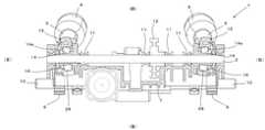
図1及び図2に示すように、第1実施形態のマッサージ装置1は、左右方向を向く軸回りに回転駆動力を発生させる回転駆動軸2と、回転駆動軸2から上方前側に伸びる第1のアーム部材3と、第1のアーム部材3の先端に設けられた第1の施療子4と、回転駆動軸2から下方前側に伸びる第2のアーム部材5と、第2のアーム部材5の先端に設けられた第2の施療子6と、を有している。これらの回転駆動軸2、第1のアーム部材3、第1の施療子4、第2のアーム部材5、及び第2の施療子6は、いずれもマッサージ基盤体7(の前部)に搭載されている。また、第1の施療子4と、第1のアーム部材3の先端との間には、バネ部材8が設けられている。 As shown in FIGS. 1 and 2, the
次に、第1実施形態のマッサージ装置1を構成するマッサージ基盤体7、回転駆動軸2、第1のアーム部材3、第1の施療子4、バネ部材8、第2のアーム部材5、第2の施療子6についてまず説明する。
なお、以降の説明において、図面の紙面に示す「前後」、「左右」、「上下」をもとに、説明を進める。この方向は、マッサージ装置1が椅子型マッサージ機の背もたれ部に内蔵された状況において、使用者(施療者)からみた「前後」、「左右」、「上下」と一致するものとなっている。Next, the
In the following explanations, the explanation will proceed based on the "front and back", "left and right", and "up and down" shown on the paper of the drawing. This direction coincides with "front and back", "left and right", and "up and down" as seen from the user (treatment person) in the situation where the
まず、マッサージ基盤体7は、板状の部材であり、硬質のプラスチックや金属などを用いて形成されている。マッサージ基盤体7の後面には、上述したガイドレールに沿ってマッサージ装置1を移動させる昇降ギヤ9と、この昇降ギヤ9を左右方向を向く軸回りに回転自在に支持する昇降軸10が設けられている。この昇降ギヤ9には、図示を省略するモータから回転駆動力が伝達されており、この昇降ギヤ9(ピニオンギア)をガイドレール(ラックギア)に噛み合わせることでマッサージ基盤体7はガイドレールの敷設方向に沿って移動可能となっている。 First, the
マッサージ基盤体7における上下方向中央部(やや上方寄り)には、マッサージ基盤体7を左右方向に横切るように回転駆動軸2が配備されている。具体的には、上述したマッサージ基盤体7の左右両側や中央側には軸受部11が設けられており、回転駆動軸2は軸受部11により左右方向を向く軸回りに回転自在に支持されている。
また、回転駆動軸2の右側には、回転駆動軸2に回転駆動力を伝達するウォームホイール12が設けられている。このウォームホイール12に対しては、マッサージ基盤体7の上部に設けられた揉みモータ13で発生した回転駆動力がウォームギヤを介して伝達され、回転駆動軸2は左右方向を向く軸回りに回転可能となっている。A
Further, on the right side of the
さらに、このウォームホイール12の左右両側の回転駆動軸2には、回転駆動軸2の回転運動を第1及び第2のアーム部材3、5に伝達し、これらのアーム部材3、5を左右方向に揺動させる傾斜ボス14が設けられている。上述した傾斜ボス14は、回転駆動軸2と同軸の円筒形状に形成されており、外周面には回転駆動軸2の軸心に対して傾斜した軸回りを周回するカム面14aが形成されている。そして、このカム面14aに対しては外側からベアリング28を介して環状嵌合部15が遊嵌している。 Further, the rotational movement of the
この環状嵌合部15は、第1のアーム部材3及び第2のアーム部材5の基端側に設けられており、上述した傾斜ボス14のカム面14aに嵌合可能な孔部16を備えている。また、環状嵌合部15の上側(図では左側)には、上方(図では左側)に向かって突出する回動規制ピン17が形成されている。この回動規制ピン17は、前後に並んで2本設けられており、2本の回動規制ピン17の間に叩き駆動軸18が挟み込まれるようになっている。この2本の回動規制ピン17の間に叩き駆動軸18を挟み込むことで、環状嵌合部15が回転駆動軸2と同伴回動することが抑制される。 The annular
それゆえ、上述した回転駆動軸2に合わせて傾斜ボス14が左右方向を向く軸回りを回動し、傾斜ボス14のカム面14aにベアリング28を介して遊嵌する環状嵌合部15も傾斜ボス14に合わせて回動しようとする。しかし、環状嵌合部15は、上述した回動規制ピン17で回動が規制されているので、環状嵌合部15が回転駆動軸2と同伴回動することはない。一方、上述したカム面14aは傾斜ボス14の外周面上を左右に蛇行するように周回するため、環状嵌合部15は同伴回動を規制された状態で左右方向にのみ往復移動する。その結果、環状嵌合部15が設けられた第1のアーム部材3及び第2のアーム部材5が左右方向に揺動する。 Therefore, the
なお、上述した環状嵌合部15は、回転駆動軸2の左端側と右端側とにそれぞれ設けられており、左端側の環状嵌合部15に設けられるカム面14aと、右端側の環状嵌合部15に設けられるカム面14aとは、傾斜方向(左右方向に沿ったカム面14aの蛇行の軌跡)が左右で逆となっている。そのため、例えば左側の第1のアーム部材3が左側に揺動した場合には、右側の第1のアーム部材3は右側に揺動し、左側の第1のアーム部材3が右側に揺動した場合には、右側の第1のアーム部材3は左側に揺動するため、左右の第1及び第2のアーム部材3、5間に位置する施療部に対してそれぞれの施療子4、6を用いた揉みマッサージを行うことができる。 The above-mentioned annular
また、回動規制ピン17の間に挟み込まれる叩き駆動軸18は、図示しない叩き駆動モータで発生する駆動力を用いて前後方向に短い時間間隔で往復移動するようになっており、これにより施療部に対する叩きマッサージを可能とする構成となっている。
第1のアーム部材3は、回転駆動軸2から上方前側に向かって伸びる長尺棒状の部材である。第1のアーム部材3の先端は、前方から見て中空コ字状に形成されており、このコ字状の部位を左右方向に貫通する貫通孔19が形成されており、左右の貫通孔19を連続して挿通するように施療子揺動軸20が配備されている。Further, the tapping
The
第1の施療子4は、先端側が半球状に形成された略円柱状であり、半球状とされた先端を施療部に押し当てることで、施療部に対するマッサージを可能としている。第1の施療子4の基端側は、マッサージ基盤体7側(下側)に向かって突出しており、この突出した基端部は上述した施療子揺動軸20で左右方向を向く軸回りに揺動自在に支持されている。 The
上述した第1のアーム部材3の先端と第1の施療子4との間には、バネ部材8が設けられている。このバネ部材8は、いわゆる「ねじりばね(トーションバネ)」であって、施療子揺動軸20を巻き回すように配備されている。ねじりばねの一方端は第1のアーム部材3の先端に係合し、ねじりばねの他方端は第1の施療子4に係合するものとされている。すなわち、バネ部材8は、第1のアーム部材3の先端と第1の施療子4とのそれぞれに跨るように取り付けられている。 A
このバネ部材8を設けることで、第1のアーム部材3の伸長方向と同方向を中立状態として、前方に折れ曲がったとしても、また後方に折れ曲がったとしても、この中立状態に復元する向きに付勢力が発生するようになっている。加えて、第1の施療子4は、左右方向を向く施療子揺動軸20に枢支されているため、左右方向(幅方向)へは折れ曲がらないものとなっている。 By providing the
第2のアーム部材5は、第1のアーム部材3とは反対に、回転駆動軸2から下方前側に向かって伸びるように形成されている。第2のアーム部材5の長さは第1のアーム部材3と略同じかやや短尺とされており、第2のアーム部材5の先端にも第1のアーム部材3と同様に第2の施療子6が設けられている。なお、第2のアーム部材5は、第2の施療子6に直接連結されており、上述した施療子揺動軸20やバネ部材8は設けられていない。つまり、第2の施療子6は、第2のアーム部材5に対して揺動しない状態で固定されている。 The
第2の施療子6は、第1の施療子4と同様に、先端側が半球状に形成された略円柱状であり、半球状とされた先端を施療部に押し当てることで、施療部に対するマッサージを可能としている。
ところで、本発明のマッサージ装置1は、上述したように第2の施療子6が第2のアーム部材5に対して揺動を規制された状態(揺動しない状態)で取り付けられている。そのため、使用者の施療部が近接して第2の施療子6に前方から過大な負荷(荷重)がかかった場合に、バネ部材などを用いて負荷を吸収することができない。Like the
By the way, in the
そこで、第1実施形態のマッサージ装置1では、第2の施療子6に過大な負荷がかかった場合に、第2の施療子6からマッサージ機構に加わる負荷を軽減する負荷軽減機構21を設けている。
具体的には、第1実施形態の負荷軽減機構21は、第2のアーム部材5を前後方向に撓ませることで、第2の施療子6から加わる負荷を吸収する構成とされている。つまり、第2のアーム部材5は、長手方向の一部に、くびれた薄肉部分22を有しており、薄肉部分22は、左右方向の幅に比べて、前後方向の厚みが薄くなる断面形状とされている。Therefore, in the
Specifically, the
次に、第1実施形態の特徴である負荷軽減機構21について詳しく説明する。
図4及び図5に示すように、第1実施形態の第2のアーム部材5は、上端側は第1のアーム部材3とほぼ同じ幅や厚みの角筒状に形成されているが、下端側(下端から上端に向かって全長の2/3までの範囲)は第1のアーム部材3の半分以下の厚みの薄肉部分22となっている。Next, the
As shown in FIGS. 4 and 5, the
具体的には、上述した薄肉部分22は、第2のアーム部材5の長手方向の一部に形成される部分であり、他の部分に比べて(薄肉部分22以外の部分に比べて)上下方向の厚みが薄くなっている。例えば、第1実施形態であれば、薄肉部分22の前後方向の厚みは、第2のアーム部材5における他の部分(例えば、左右方向の幅)の1/3程度とされており、厚みが薄い分だけ前後方向に沿って撓みやすくなっている。これに対して、第1のアーム部材3は、左右方向の幅と、上下方向の厚みとがほぼ等しい角柱状に形成されており、第2のアーム部材5自身が撓むことはほとんどない。 Specifically, the thin-
上述した第1実施形態の負荷軽減機構21を設ければ、使用者の施療部が第2の施療子6に近接して、第2の施療子6に前方から過大な負荷が加わると、第2のアーム部材5が薄肉部分22を中心に後方に撓み、第2のアーム部材5が撓むことで負荷を吸収することが可能となる。
具体例を挙げて説明すれば、上述した負荷軽減機構21は、次のように動作して、負荷を軽減する。If the
To give a specific example, the
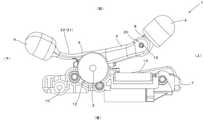
すなわち、図4に示すように、使用者の施療部が施療子に非接触で、第1及び第2の施療子4、6の双方に負荷が加わっていない状態(無負荷状態)のマッサージ装置1を考える。
図4の無負荷状態のマッサージ装置1では、第1のアーム部材3は回転駆動軸2から上方前側に伸び、第2のアーム部材5は回転駆動軸2から下方前側に伸びている。そして、第1の施療子4は第1のアーム部材3の先端からさらに上方前側に突出し、第2の施療子6は第2のアーム部材5の先端からさらに下方前側に突出した状態となっている。That is, as shown in FIG. 4, the massage device in a state where the treatment unit of the user is not in contact with the treatment child and no load is applied to both the first and
In the
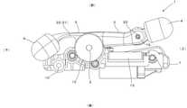
上述したマッサージ装置1において、使用者の施療部が施療子に強く接して、第1及び第2の施療子4、6に対して前方から大きな負荷(大きな荷重)を加える。
そうすると、図5に示すように、第1の施療子4が施療子揺動軸20を中心に後方に揺動し、第1の施療子4の後方揺動に合わせてバネ部材8に復元力が働いて、第1の施療子4に加わった負荷を吸収する。つまり、第1の施療子4では、前方からの負荷をバネ部材8が弾性変形して吸収する。加えて、第1の施療子4は、左右方向を向く施療子揺動軸20に枢支されているため、左右方向(幅方向)へは折れ曲がらないため、揉みマッサージ(施療子の左右近接離反動作)において、施療部に対して確実に力を伝達することができ、好適なマッサージを行うことができる。In the
Then, as shown in FIG. 5, the
一方、バネ部材を有さない第2の施療子6では、前方から加えられる大きな負荷(大きな荷重)に対して、バネ部材を弾性変形させることができない。そこで、第2の施療子6では、第2のアーム部材5が薄肉部分22を中心に後方に湾曲するように撓んで、負荷を吸収する。
この第2のアーム部材5の湾曲は基端に対して先端が下方後側に向かって緩やかに湾曲するものであり、撓んだ第2の施療子6の位置は第2のアーム部材5よりも後方まで後退する。このような第2のアーム部材5の湾曲(撓曲)により、第2の施療子6に加わった負荷も吸収される。On the other hand, in the
The curvature of the
上述した負荷軽減機構21を設ければ、使用者の施療部が第2の施療子6に強く接した際に、第2の施療子6に大きな負荷が加わっても、この負荷が負荷軽減機構21により吸収され、マッサージ機構に直接負荷や衝撃が加わることがない。そのため、本実施形態のマッサージ装置1では、マッサージ機構に対する破損を抑制することができるし、マッサージ時に施療子(特に、第2の施療子6)が強く当たったり擦れたりして施療者に不快な思いをさせることもない。 If the above-mentioned
この第2のアーム部材5の湾曲は専ら前後方向に沿ったものとなり、左右方向には殆ど湾曲しなくなる。つまり、第2のアーム部材5を左右方向に揺動させて第2の施療子6で施療部を揉みマッサージする場合でも、薄肉部分22は殆ど左右方向には撓まず、第2のアーム部材5は変形を起こすことがない。そのため、施療部に対して十分な揉みマッサージ力を発揮することが可能となる。
[第2実施形態]
次に、第2実施形態のマッサージ装置1について説明する。The curvature of the
[Second Embodiment]
Next, the
図6~図10は、第2実施形態のマッサージ装置1を模式的に示したものである。
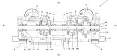
図6及び図7に示すように、第2実施形態のマッサージ装置1は、第1実施形態と同様に、左右方向を向く軸回りに回転駆動力を発生させる回転駆動軸2、回転駆動軸2から上方前側に伸びる第1のアーム部材3、第1のアーム部材3の先端に設けられた第1の施療子4、回転駆動軸2から下方前側に伸びる第2のアーム部材5、第2のアーム部材5の先端に設けられた第2の施療子6を有している。6 to 10 schematically show the
As shown in FIGS. 6 and 7, the
また、第2実施形態の回転駆動軸2にも、第1実施形態と同様に傾斜ボス14、環状嵌合部15、回動規制ピン17、叩き駆動軸18、揉みモータ13、叩き駆動モータなどが設けられている。
加えて、第1のアーム部材3の先端と第1の施療子4との間には、第1実施形態と略同様にバネ部材8が配備されている。Further, the
In addition, a
第2実施形態で大きく異なるのは、負荷軽減機構21の構成である。
第2実施形態の負荷軽減機構21が第1実施形態と異なる点は、第2実施形態のマッサージ装置1が上述したバネ部材8(第1のアーム部材3の先端に設けられたバネ部材8)の付勢力を第1のアーム部材3及び第2のアーム部材5を介して第2の施療子6に伝達させることで、第2の施療子6に加わる負荷を第1の施療子4側に設けられたバネ部材8で吸収可能な構成とされている点である。What is significantly different in the second embodiment is the configuration of the
The difference between the
具体的には、第2実施形態のマッサージ装置1に設けられる負荷軽減機構21は、上述したバネ部材8と、第1のアーム部材3及び第2のアーム部材5が設けられたマッサージ基盤体7と、マッサージ基盤体7を、所定の揺動角に亘って左右方向を向く軸回りに揺動可能に支持するフレーム体23と、を備えている。
つまり、第2実施形態のマッサージ装置1は、第1のアーム部材3、第2のアーム部材5などを支持するマッサージ基盤体7と、このマッサージ基盤体7を左右軸心回りに揺動自在に枢支するフレーム体23とを有している。Specifically, the
That is, in the
以降、第2実施形態の負荷軽減機構21を構成するバネ部材8、マッサージ基盤体7、及びフレーム体23について説明する。
図6及び図7に示すように、第2実施形態のマッサージ装置1に設けられるフレーム体23は、上方から見た場合に四角形状の平坦な枠部材である。フレーム体23の中央には前後方向にフレーム体23を貫通する開口が形成されており、この開口に上述したマッサージ基盤体7が収容可能とされている。また、フレーム体23の下部には、回転駆動力を発生させている昇降駆動モータ、この昇降駆動モータで発生した回転駆動力を昇降軸10に伝達する動力伝達部(昇降用のウォームギヤ及びウォームホイール12)、この動力伝達部を介して伝達された回転駆動力を用いて左右方向を向く軸心回りに回転自在に配備された昇降軸10などが配備されている。Hereinafter, the
As shown in FIGS. 6 and 7, the
また、上述したフレーム体23の左右両側には、上方に向かって起立した側壁部24が形成されている。この側壁部24には、左右いずれのものにも、側壁部24を左右方向に貫通する軸孔25が形成されている。そして、これら左右の軸孔25間を結ぶように、回転駆動軸2が左右方向に架設された状態で、左右方向を向く軸回りに回転自在に配備されている。 Further, on the left and right sides of the
マッサージ基盤体7は、水平方向に比べて上下方向に厚みの薄い板状の部材であり、硬質のプラスチックや金属などを用いて上述したフレーム体23の開口に収まる寸法に形成されている。このマッサージ基盤体7の前面には、回転駆動軸2、この回転駆動軸2を回転自在に支持する軸受部11、第1及び第2のアーム部材3、5、回転駆動軸2の回転駆動力を第1及び第2のアーム部材3、5の揺動動作に変換する動力伝達機構(上述した傾斜ボス14、環状嵌合部15、回動規制ピン17などで構成される機構)が配備されている。 The
また、マッサージ基盤体7の後面には、回転駆動軸2を回転させる揉みモータ13、さらには叩きマッサージを行う叩き駆動軸18や叩き駆動用モータなどが配備されている。
上述した回転駆動軸2は、マッサージ基盤体7とフレーム体23との双方に連通するように配備されており、回転駆動軸2を用いてマッサージ基盤体7はフレーム体23に対して左右方向を向く軸回りに揺動自在(前後方向に揺動自在)とされている。第2実施形態の場合、この揺動の軸心が回転駆動軸2の軸心と一致する。すなわち、回転駆動軸2は、第1及び第2のアーム部材3、5を駆動する駆動力を伝達すると共に、マッサージ基盤体7をフレーム体23に対して前後方向に揺動自在に支持するものとなっている。Further, on the rear surface of the
The
さらに、フレーム体23には、マッサージ基盤体7の一部が接触してマッサージ基盤体7の前方揺動を規制する第1規制部26と、マッサージ基盤体7の一部が接触してマッサージ基盤体7の後方揺動を規制する第2規制部27と、が設けられている。
第1規制部26は、マッサージ基盤体7が接触してマッサージ基盤体7の前方揺動を規制する部材であり、本実施形態ではマッサージ基盤体7の上面に接触することでマッサージ基盤体7の前方揺動を規制している。Further, a part of the
The
具体的には、本実施形態の第1規制部26は、フレーム体23の側壁部24の内面、言い換えれば側壁部24における回転駆動軸2のウォームホイール12側を向く面に設けられている。この第1規制部26は、幅方向内側(ウォームホイール12側)に向かって突出して形成されており、突出部の後面をマッサージ基盤体7の前面に接触させることができる構成となっている。 Specifically, the first regulating
そのため、図10に示すように回転駆動軸2の軸心回りにマッサージ基盤体7を前方揺動させてゆく(第1のアーム部材3を前側に倒してゆく)と、所定の揺動角だけ前方揺動させた段階(本実施形態の場合であれば11~12°揺動させた段階)で、マッサージ基盤体7の前面が第1規制部26に接触し、これ以上の前方揺動が規制される。
第2規制部27は、マッサージ基盤体7に接触してマッサージ基盤体7の後方揺動を規制する部材であり、本実施形態ではマッサージ基盤体7の後面に接触することでマッサージ基盤体7の後方揺動を規制している。Therefore, as shown in FIG. 10, when the
The
具体的には、本実施形態の第2規制部27は、フレーム体23の開口(フレーム体23の後面)を左右方向に横断するように配備された板体であり、マッサージ基盤体7を後方に揺動させ、フレーム体23内にマッサージ基盤体7が沈んだ状態となった際に、この板体にマッサージ基盤体7の後面が接触するものとなっている。
そのため、図9に示すように回転駆動軸2の軸心回りにマッサージ基盤体7を後方揺動させてゆくと、所定の揺動角だけ後方揺動させた段階(本実施形態の場合であればマッサージ基盤体7の後面が上下方向を向くまで揺動させた段階)で、マッサージ基盤体7の後面が第2規制部27の前面に接触し、これ以上の後方揺動が規制される。Specifically, the
Therefore, as shown in FIG. 9, when the
上述した第2実施形態の負荷軽減機構21を設ければ、使用者の施療部が施療子(特に、第2の施療子6)に強く接した状況で、第2の施療子6に大きな負荷が加わっても、この負荷が負荷軽減機構21により第1の施療子4の近傍に設けられたバネ部材8に伝達し、バネ部材8が弾性変形して負荷を吸収するため、マッサージ機構に直接負荷や衝撃が加わることがない。すなわち、フレーム体23に対してマッサージ基盤体7が前後揺動するため、第2の施療子6に加わった大きな負荷(大きな荷重)は、マッサージ基盤体7の揺動(シーソー状の動き)を介して、第1の施療子4の基端にあるバネ部材8に伝達し、バネ部材8の弾性力が反作用的に第2の施療子6に伝わる。そのため、あたかも第2の施療子6の基端にもバネ部材8が存在するように作用し、マッサージ装置1に対する破損を抑制することができるし、使用者の施療部に施療子が強く当たったとしても、第1の施療子4及び第2の施療子6は後方へ逃げるような動作を行い、施療者に不快な思いをさせることはない。 If the
なお、今回開示された実施形態はすべての点で例示であって制限的なものではないと考えられるべきである。特に、今回開示された実施形態において、明示的に開示されていない事項、例えば、運転条件、各種パラメータ、構成物の寸法、重量、体積などは、当業者が通常実施する範囲を逸脱するものではなく、通常の当業者であれば、容易に想定することが可能な値を採用している。 It should be noted that the embodiments disclosed this time are exemplary in all respects and are not restrictive. In particular, in the embodiments disclosed this time, matters not explicitly disclosed, such as operating conditions, various parameters, dimensions, weights, volumes, etc. of components, do not deviate from the range normally implemented by those skilled in the art. However, a value that can be easily assumed by a person skilled in the art is adopted.
1 マッサージ装置
2 回転駆動軸
3 第1のアーム部材
4 第1の施療子
5 第2のアーム部材
6 第2の施療子
7 マッサージ基盤体
8 バネ部材
9 昇降ギヤ
10 昇降軸
11 軸受部
12 ウォームホイール
13 揉みモータ
14 傾斜ボス
14a カム面
15 環状嵌合部
16 孔部
17 回動規制ピン
18 叩き駆動軸
19 貫通孔
20 施療子揺動軸
21 負荷軽減機構
22 薄肉部分
23 フレーム体
24 側壁部
25 軸孔
26 第1規制部
27 第2規制部
28 ベアリング1
Claims (4)
Translated fromJapanese前記アーム部材には、前記施療子からアーム部材側に加わる負荷を吸収する負荷軽減機構が設けられており、前記負荷軽減機構は、前後方向に沿った付勢力を利用して前記施療子への負荷を吸収する構成とされており、
前記アーム部材は、第1のアーム部材と第2のアーム部材とを有し、
前記第1のアーム部材は、回転駆動力を発生させる回転駆動軸に交差するように一方側に向かって伸びるものとされ、前記第2のアーム部材は、前記回転駆動軸に交差するように他方側に向かって伸びるものとされており、前記第1のアーム部材の先端には第1の施療子が設けられ、前記第2のアーム部材の先端には第2の施療子が設けられていて、
前記負荷軽減機構は、前記第1のアーム部材と第1の施療子との間に配備されて前記回転駆動軸に平行な軸心回りに付勢されたバネ部材と、前記アーム部材を回転駆動軸回りに揺動自在の支持する支持構造とを有している
ことを特徴とするマッサージ装置。A massage device including a treatment child that treats a treatment unit of a user and an arm member to which the treatment child is attached to the tip.
The arm member is provided with a load reduction mechanism that absorbs a load applied to the arm member side from the treatment child, and the load reduction mechanism utilizes an urging force along the front-rear direction to the treatment child. Itis configured to absorb the load,
The arm member has a first arm member and a second arm member.
The first arm member is assumed to extend toward one side so as to intersect the rotation drive shaft that generates a rotation drive force,and the second arm member extends toward one side so as to intersect the rotation drive shaft.It is supposed to extend toward the side, and a first treatment child is provided at the tipof the first arm member, and a second treatment child is provided at the tip of the second arm member. ,
The load reducing mechanism is a spring member deployed between the first arm member and the first treatment element and urged around the axis parallel to the rotation drive axis, and the arm member is rotationally driven. It has a support structure that supports swinging around the axis.
A massage device that features that.
ことを特徴とする請求項1に記載のマッサージ装置。The load reducing mechanism includesa thin-walled portion formed in a part of the second arm member in the longitudinal direction, and the second arm member is flexed in the front-rear direction by elastic deformation of the thin-walled portion . The massage device according to claim 1, wherein the urging force is generated along the front-rear direction.
前記マッサージ基盤体を、所定の揺動角に亘って前記回転駆動軸回りに揺動可能に支持するフレーム体と、
を備えていることを特徴とする請求項1~3のいずれかに記載のマッサージ装置。The massage base body to which the first arm member and the second arm member are deployed, and
A frame body that swingably supports the massage base body around the rotation drive axis over a predetermined swing angle, and
The massage device according to any one of claims1 to 3 , wherein the massage device is provided.
Priority Applications (6)
| Application Number | Priority Date | Filing Date | Title |
|---|---|---|---|
| JP2018153594AJP7001269B2 (en) | 2018-08-17 | 2018-08-17 | Massage device |
| SG11202009265RASG11202009265RA (en) | 2018-08-17 | 2019-05-17 | Massaging apparatus |
| PCT/JP2019/019690WO2020035978A1 (en) | 2018-08-17 | 2019-05-17 | Massaging device |
| US16/982,220US20210361520A1 (en) | 2018-08-17 | 2019-05-17 | Massaging apparatus |
| CN201980004255.6ACN111065365B (en) | 2018-08-17 | 2019-05-17 | massage device |
| TW108118498ATWI802702B (en) | 2018-08-17 | 2019-05-29 | massage device |
Applications Claiming Priority (1)
| Application Number | Priority Date | Filing Date | Title |
|---|---|---|---|
| JP2018153594AJP7001269B2 (en) | 2018-08-17 | 2018-08-17 | Massage device |
Publications (2)
| Publication Number | Publication Date |
|---|---|
| JP2020025818A JP2020025818A (en) | 2020-02-20 |
| JP7001269B2true JP7001269B2 (en) | 2022-02-03 |
Family
ID=69525405
Family Applications (1)
| Application Number | Title | Priority Date | Filing Date |
|---|---|---|---|
| JP2018153594AActiveJP7001269B2 (en) | 2018-08-17 | 2018-08-17 | Massage device |
Country Status (6)
| Country | Link |
|---|---|
| US (1) | US20210361520A1 (en) |
| JP (1) | JP7001269B2 (en) |
| CN (1) | CN111065365B (en) |
| SG (1) | SG11202009265RA (en) |
| TW (1) | TWI802702B (en) |
| WO (1) | WO2020035978A1 (en) |
Citations (1)
| Publication number | Priority date | Publication date | Assignee | Title |
|---|---|---|---|---|
| JP2018102794A (en) | 2016-12-28 | 2018-07-05 | 大東電機工業株式会社 | Massage mechanism and chair-type massage machine |
Family Cites Families (25)
| Publication number | Priority date | Publication date | Assignee | Title |
|---|---|---|---|---|
| JPS49142993U (en)* | 1973-04-06 | 1974-12-10 | ||
| JPS5551455Y2 (en)* | 1977-06-16 | 1980-12-01 | ||
| JP3291332B2 (en)* | 1992-10-19 | 2002-06-10 | 三洋電機株式会社 | Massage machine |
| US5803916A (en)* | 1996-03-19 | 1998-09-08 | Vital-Tech Ltd. | Body and joints massage device |
| JPH11332931A (en)* | 1999-05-12 | 1999-12-07 | Family Kk | Massage driving part and chair-shaped massage equipment |
| JP4020581B2 (en)* | 2000-11-15 | 2007-12-12 | 三洋電機株式会社 | Chair type massage machine |
| KR20020089883A (en)* | 2001-05-25 | 2002-11-30 | 주식회사 지인텍 | Massage device |
| JP3977175B2 (en)* | 2001-12-27 | 2007-09-19 | リビングテクノロジー株式会社 | Massage machine |
| JP2003325618A (en)* | 2002-05-14 | 2003-11-18 | Omron Corp | Massager |
| JP2005230399A (en)* | 2004-02-23 | 2005-09-02 | Fuji Iryoki:Kk | Massage machine |
| TWI268775B (en)* | 2004-07-27 | 2006-12-21 | Matsushita Electric Works Ltd | Massager |
| JP4720698B2 (en)* | 2006-09-20 | 2011-07-13 | パナソニック電工株式会社 | Massage machine |
| CN201337626Y (en)* | 2008-12-29 | 2009-11-04 | 北京怡莲礼业科技发展有限公司 | Flexible kneading apparatus |
| JP5242526B2 (en)* | 2009-09-18 | 2013-07-24 | パナソニック株式会社 | Massage machine |
| JP2011131039A (en)* | 2009-11-24 | 2011-07-07 | Daito Denki Kogyo Kk | Back massage device provided to chair type massage machine and chair type massage machine with same |
| JP5766489B2 (en)* | 2011-04-07 | 2015-08-19 | ファミリーイナダ株式会社 | Massage machine |
| JP6238619B2 (en)* | 2013-07-29 | 2017-11-29 | 大東電機工業株式会社 | Massage device and chair type massage machine equipped with this massage device |
| TWI539943B (en)* | 2013-08-16 | 2016-07-01 | Massage machine | |
| WO2015083967A1 (en)* | 2013-12-06 | 2015-06-11 | 주식회사 세라젬 | Probe structure for thermotherapy device |
| CN105078696A (en)* | 2014-04-16 | 2015-11-25 | 宁波秉航电子科技有限公司 | Massage chair with curved guide rail |
| JP6607443B2 (en)* | 2015-09-30 | 2019-11-20 | パナソニックIpマネジメント株式会社 | Massage machine |
| JP6627114B2 (en)* | 2016-10-20 | 2020-01-08 | 大東電機工業株式会社 | Massage machine |
| US10485727B2 (en)* | 2016-12-12 | 2019-11-26 | James E Grove | Piston actuated lumbar stimulation device for a chair |
| CN206852769U (en)* | 2017-01-17 | 2018-01-09 | 深圳市福瑞斯保健器材有限公司 | A kind of massager core and its massager |
| JP6723560B2 (en)* | 2017-07-24 | 2020-07-15 | 大東電機工業株式会社 | Massage machine |
- 2018
- 2018-08-17JPJP2018153594Apatent/JP7001269B2/enactiveActive
- 2019
- 2019-05-17USUS16/982,220patent/US20210361520A1/ennot_activeAbandoned
- 2019-05-17CNCN201980004255.6Apatent/CN111065365B/enactiveActive
- 2019-05-17SGSG11202009265RApatent/SG11202009265RA/enunknown
- 2019-05-17WOPCT/JP2019/019690patent/WO2020035978A1/ennot_activeCeased
- 2019-05-29TWTW108118498Apatent/TWI802702B/enactive
Patent Citations (1)
| Publication number | Priority date | Publication date | Assignee | Title |
|---|---|---|---|---|
| JP2018102794A (en) | 2016-12-28 | 2018-07-05 | 大東電機工業株式会社 | Massage mechanism and chair-type massage machine |
Also Published As
| Publication number | Publication date |
|---|---|
| SG11202009265RA (en) | 2020-10-29 |
| WO2020035978A1 (en) | 2020-02-20 |
| TW202008979A (en) | 2020-03-01 |
| US20210361520A1 (en) | 2021-11-25 |
| TWI802702B (en) | 2023-05-21 |
| CN111065365B (en) | 2022-12-09 |
| JP2020025818A (en) | 2020-02-20 |
| CN111065365A (en) | 2020-04-24 |
Similar Documents
| Publication | Publication Date | Title |
|---|---|---|
| TWI511722B (en) | A massage device, and a seat massager provided with the massage device | |
| CN101711717B (en) | Massage unit and chair-type massage machine having the unit | |
| CN107822843B (en) | Massage device | |
| CN108472195B (en) | Massage device | |
| JP6605443B2 (en) | Massage mechanism and chair type massage machine | |
| JP6165031B2 (en) | Massage machine | |
| JP7001269B2 (en) | Massage device | |
| JP4215732B2 (en) | Massage machine | |
| JP4710759B2 (en) | Massage machine | |
| HK40026615A (en) | Massaging device | |
| HK40026615B (en) | Massaging device | |
| WO2016117171A1 (en) | Massage mechanism | |
| CN221814633U (en) | Fat grinding machine | |
| JP2020031921A (en) | Massage unit and massage machine | |
| JP4070773B2 (en) | Massage machine | |
| KR101242077B1 (en) | Massage module and massage apparatus having the same | |
| JP4507702B2 (en) | Massage machine | |
| JP2001120624A (en) | Massaging unit and chair type massaging machine provided with that unit | |
| HK1253917B (en) | Massage machine | |
| JPH1028709A (en) | Massaging apparatus provided with means for adjusting action intensity | |
| HK1238127B (en) | Massage device and massage chair provided with same | |
| HK1224915A1 (en) | Massage device | |
| JP2001224644A (en) | Massaging machine | |
| HK1249004B (en) | Massage device | |
| HK1216712B (en) | Massage device |
Legal Events
| Date | Code | Title | Description |
|---|---|---|---|
| A621 | Written request for application examination | Free format text:JAPANESE INTERMEDIATE CODE: A621 Effective date:20201019 | |
| A131 | Notification of reasons for refusal | Free format text:JAPANESE INTERMEDIATE CODE: A131 Effective date:20210713 | |
| A521 | Request for written amendment filed | Free format text:JAPANESE INTERMEDIATE CODE: A523 Effective date:20210820 | |
| TRDD | Decision of grant or rejection written | ||
| A01 | Written decision to grant a patent or to grant a registration (utility model) | Free format text:JAPANESE INTERMEDIATE CODE: A01 Effective date:20211214 | |
| A61 | First payment of annual fees (during grant procedure) | Free format text:JAPANESE INTERMEDIATE CODE: A61 Effective date:20211217 | |
| R150 | Certificate of patent or registration of utility model | Ref document number:7001269 Country of ref document:JP Free format text:JAPANESE INTERMEDIATE CODE: R150 | |
| R250 | Receipt of annual fees | Free format text:JAPANESE INTERMEDIATE CODE: R250 |