JP6995987B2 - NR V2X 2-step SCI transmission - Google Patents
NR V2X 2-step SCI transmissionDownload PDFInfo
- Publication number
- JP6995987B2 JP6995987B2JP2020521338AJP2020521338AJP6995987B2JP 6995987 B2JP6995987 B2JP 6995987B2JP 2020521338 AJP2020521338 AJP 2020521338AJP 2020521338 AJP2020521338 AJP 2020521338AJP 6995987 B2JP6995987 B2JP 6995987B2
- Authority
- JP
- Japan
- Prior art keywords
- sci
- information
- resource
- pscch
- communication
- Prior art date
- Legal status (The legal status is an assumption and is not a legal conclusion. Google has not performed a legal analysis and makes no representation as to the accuracy of the status listed.)
- Active
Links
Images


Classifications
- H—ELECTRICITY
- H04—ELECTRIC COMMUNICATION TECHNIQUE
- H04W—WIRELESS COMMUNICATION NETWORKS
- H04W72/00—Local resource management
- H04W72/20—Control channels or signalling for resource management
- H04W72/25—Control channels or signalling for resource management between terminals via a wireless link, e.g. sidelink
- H—ELECTRICITY
- H04—ELECTRIC COMMUNICATION TECHNIQUE
- H04W—WIRELESS COMMUNICATION NETWORKS
- H04W72/00—Local resource management
- H04W72/12—Wireless traffic scheduling
- H04W72/1263—Mapping of traffic onto schedule, e.g. scheduled allocation or multiplexing of flows
- H—ELECTRICITY
- H04—ELECTRIC COMMUNICATION TECHNIQUE
- H04L—TRANSMISSION OF DIGITAL INFORMATION, e.g. TELEGRAPHIC COMMUNICATION
- H04L1/00—Arrangements for detecting or preventing errors in the information received
- H04L1/0001—Systems modifying transmission characteristics according to link quality, e.g. power backoff
- H04L1/0002—Systems modifying transmission characteristics according to link quality, e.g. power backoff by adapting the transmission rate
- H04L1/0003—Systems modifying transmission characteristics according to link quality, e.g. power backoff by adapting the transmission rate by switching between different modulation schemes
- H—ELECTRICITY
- H04—ELECTRIC COMMUNICATION TECHNIQUE
- H04L—TRANSMISSION OF DIGITAL INFORMATION, e.g. TELEGRAPHIC COMMUNICATION
- H04L1/00—Arrangements for detecting or preventing errors in the information received
- H04L1/0001—Systems modifying transmission characteristics according to link quality, e.g. power backoff
- H04L1/0009—Systems modifying transmission characteristics according to link quality, e.g. power backoff by adapting the channel coding
- H—ELECTRICITY
- H04—ELECTRIC COMMUNICATION TECHNIQUE
- H04L—TRANSMISSION OF DIGITAL INFORMATION, e.g. TELEGRAPHIC COMMUNICATION
- H04L1/00—Arrangements for detecting or preventing errors in the information received
- H04L1/12—Arrangements for detecting or preventing errors in the information received by using return channel
- H04L1/16—Arrangements for detecting or preventing errors in the information received by using return channel in which the return channel carries supervisory signals, e.g. repetition request signals
- H04L1/18—Automatic repetition systems, e.g. Van Duuren systems
- H04L1/1812—Hybrid protocols; Hybrid automatic repeat request [HARQ]
- H—ELECTRICITY
- H04—ELECTRIC COMMUNICATION TECHNIQUE
- H04L—TRANSMISSION OF DIGITAL INFORMATION, e.g. TELEGRAPHIC COMMUNICATION
- H04L5/00—Arrangements affording multiple use of the transmission path
- H04L5/003—Arrangements for allocating sub-channels of the transmission path
- H04L5/0053—Allocation of signalling, i.e. of overhead other than pilot signals
- H—ELECTRICITY
- H04—ELECTRIC COMMUNICATION TECHNIQUE
- H04L—TRANSMISSION OF DIGITAL INFORMATION, e.g. TELEGRAPHIC COMMUNICATION
- H04L5/00—Arrangements affording multiple use of the transmission path
- H04L5/0091—Signalling for the administration of the divided path, e.g. signalling of configuration information
- H04L5/0094—Indication of how sub-channels of the path are allocated
- H—ELECTRICITY
- H04—ELECTRIC COMMUNICATION TECHNIQUE
- H04W—WIRELESS COMMUNICATION NETWORKS
- H04W4/00—Services specially adapted for wireless communication networks; Facilities therefor
- H04W4/30—Services specially adapted for particular environments, situations or purposes
- H04W4/40—Services specially adapted for particular environments, situations or purposes for vehicles, e.g. vehicle-to-pedestrians [V2P]
- H—ELECTRICITY
- H04—ELECTRIC COMMUNICATION TECHNIQUE
- H04W—WIRELESS COMMUNICATION NETWORKS
- H04W72/00—Local resource management
- H04W72/02—Selection of wireless resources by user or terminal
- H—ELECTRICITY
- H04—ELECTRIC COMMUNICATION TECHNIQUE
- H04W—WIRELESS COMMUNICATION NETWORKS
- H04W72/00—Local resource management
- H04W72/20—Control channels or signalling for resource management
- H—ELECTRICITY
- H04—ELECTRIC COMMUNICATION TECHNIQUE
- H04W—WIRELESS COMMUNICATION NETWORKS
- H04W72/00—Local resource management
- H04W72/50—Allocation or scheduling criteria for wireless resources
- H04W72/56—Allocation or scheduling criteria for wireless resources based on priority criteria
- H04W72/566—Allocation or scheduling criteria for wireless resources based on priority criteria of the information or information source or recipient
- H04W72/569—Allocation or scheduling criteria for wireless resources based on priority criteria of the information or information source or recipient of the traffic information
- H—ELECTRICITY
- H04—ELECTRIC COMMUNICATION TECHNIQUE
- H04W—WIRELESS COMMUNICATION NETWORKS
- H04W72/00—Local resource management
- H04W72/04—Wireless resource allocation
- H04W72/044—Wireless resource allocation based on the type of the allocated resource
- H04W72/0446—Resources in time domain, e.g. slots or frames
- H—ELECTRICITY
- H04—ELECTRIC COMMUNICATION TECHNIQUE
- H04W—WIRELESS COMMUNICATION NETWORKS
- H04W72/00—Local resource management
- H04W72/04—Wireless resource allocation
- H04W72/044—Wireless resource allocation based on the type of the allocated resource
- H04W72/0453—Resources in frequency domain, e.g. a carrier in FDMA
- H—ELECTRICITY
- H04—ELECTRIC COMMUNICATION TECHNIQUE
- H04W—WIRELESS COMMUNICATION NETWORKS
- H04W92/00—Interfaces specially adapted for wireless communication networks
- H04W92/16—Interfaces between hierarchically similar devices
- H04W92/18—Interfaces between hierarchically similar devices between terminal devices
Landscapes
- Engineering & Computer Science (AREA)
- Signal Processing (AREA)
- Computer Networks & Wireless Communication (AREA)
- Quality & Reliability (AREA)
- Mobile Radio Communication Systems (AREA)
Description
Translated fromJapanese本開示は、無線通信システムに関する。 The present disclosure relates to wireless communication systems.
サイドリンク(sidelink、SL)とは、端末(User Equipment、UE)間に直接的なリンクを設定し、基地局(Base Station、BS)を経ずに、端末間に音声またはデータなどを直接やり取りする通信方式を意味する。SLは、急速に増加するデータトラフィックによる基地局の負担を解決することができる一つの方案として考慮されている。 With a side link (sidelink, SL), a direct link is set between terminals (User Equipment, UE), and voice or data is directly exchanged between terminals without going through a base station (Base Station, BS). Means the communication method to be used. SL is considered as one of the measures that can solve the burden on the base station due to the rapidly increasing data traffic.
V2X(vehicle-to-everything)は、有/無線通信を介して他の車両、歩行者、インフラが構築されたモノなどと情報を交換する通信技術を意味する。V2Xは、V2V(vehicle-to-vehicle)、V2I(vehicle-to-infrastructure)、V2N(vehicle-to-network)、及びV2P(vehicle-to-pedestrian)のような四つの類型に区分されることができる。V2X通信は、PC5インターフェース及び/またはUuインターフェースを介して提供されることができる。 V2X (Vehicle-to-Everything) means a communication technology for exchanging information with other vehicles, pedestrians, objects with built infrastructure, etc. via wireless communication. V2X is classified into four types such as V2V (vehicle-to-vehicle), V2I (vehicle-to-infrastructure), V2N (vehicle-to-newwork), and V2P (vehicle-to-pedestrian). Can be done. V2X communication can be provided via the PC5 interface and / or the Uu interface.
一方、一層多くの通信機器が一層大きい通信容量を要求するにつれて、既存の無線アクセス技術(Radio Access Technology、RAT)に比べて向上したモバイル広帯域(mobile broadband)通信に対する必要性が台頭されている。それによって、信頼度(reliability)及び遅延(latency)に敏感なサービスまたは端末を考慮した通信システムが論議されており、改善された移動広帯域通信、マッシブMTC(Machine Type Communication)、URLLC(Ultra-Reliable and Low Latency Communication)などを考慮した次世代無線接続技術を新しいRAT(new radio access technology)またはNR(new radio)と称することができる。NRでもV2X(vehicle-to-everything)通信がサポートされることができる。 On the other hand, as more and more communication devices demand larger communication capacities, the need for mobile broadband communication, which is improved compared to existing radio access technologies (Radio Access Technology, RAT), is emerging. Thereby, communication systems considering services or terminals that are sensitive to reliability and latency are being discussed, and improved mobile broadband communication, Massive MTC (Machine Type Communication), URLLC (Ultra-Reliable). Next-generation wireless connection technology considering and Low Latency Communication can be referred to as a new RAT (new radio access technology) or NR (new radio). V2X (vehicle-to-everaging) communication can also be supported in NR.
図1は、NR以前のRATに基づくV2X通信とNRに基づくV2X通信を比較して説明するための図面である。図1の実施例は、本開示の多様な実施例と結合されることができる。 FIG. 1 is a drawing for comparing and explaining V2X communication based on RAT before NR and V2X communication based on NR. The examples of FIG. 1 can be combined with the various examples of the present disclosure.
V2X通信と関連して、NR以前のRATではBSM(Basic Safety Message)、CAM(Cooperative Awareness Message)、DENM(Decentralized Environmental Notification Message)のようなV2Xメッセージに基づいて、安全サービス(safety service)を提供する方案が主に論議された。V2Xメッセージは、位置情報、動的情報、属性情報などを含むことができる。例えば、端末は、周期的なメッセージ(periodic message)タイプのCAM、及び/またはイベントトリガメッセージ(event triggered message)タイプのDENMを他の端末に送信できる。 In connection with V2X communication, in RAT before NR, BSM (Basic Safety Message), CAM (Cooperative Awareness Message), DENM (Decentralized Environment Message), service provided by Service, etc. The plan to do so was mainly discussed. The V2X message can include location information, dynamic information, attribute information, and the like. For example, a terminal can send a periodic message type CAM and / or an event triggered message type DENM to another terminal.
例えば、CAMは、方向及び速度のような車両の動的状態情報、寸法のような車両静的データ、外部照明状態、経路内訳など、基本車両情報を含むことができる。例えば、端末は、CAMを放送することができ、CAMの遅延(latency)は、100msより小さい。例えば、車両の故障、事故などの突発的な状況が発生する場合、端末は、DENMを生成して他の端末に送信できる。例えば、端末の送信範囲内にある全ての車両は、CAM及び/またはDENMを受信することができる。この場合、DENMは、CAMより高い優先順位を有することができる。 For example, the CAM can include basic vehicle information such as vehicle dynamic state information such as direction and speed, vehicle static data such as dimensions, external lighting state, route breakdown, and the like. For example, the terminal can broadcast the CAM and the latency of the CAM is less than 100 ms. For example, in the event of a sudden situation such as a vehicle breakdown or accident, the terminal can generate a DENM and send it to another terminal. For example, all vehicles within the transmission range of the terminal can receive CAM and / or DENM. In this case, DENM can have a higher priority than CAM.
以後、V2X通信と関連して、多様なV2XシナリオがNRで提示されている。例えば、多様なV2Xシナリオは、車両プラトー二ング(vehicle platooning)、向上したドライビング(advanced driving)、拡張されたセンサ(extended sensors)、リモートドライビング(remoted riving)などを含むことができる。 Since then, various V2X scenarios have been presented in NR in connection with V2X communication. For example, various V2X scenarios can include vehicle vehicle lighting, advanced driving, extended sensors, remote driving, and the like.
例えば、車両プラトー二ングに基づいて、車両は、動的にグループを形成して共に移動できる。例えば、車両プラトー二ングに基づくプラトーン動作(platoon operations)を実行するために、前記グループに属する車両は、先頭車両から周期的なデータを受信することができる。例えば、前記グループに属する車両は、周期的なデータを利用することで、車両間の間隔を減らしたり増やしたりすることができる。 For example, based on vehicle plateauning, vehicles can dynamically form groups and move together. For example, in order to perform platoon operations based on vehicle plateoning, vehicles belonging to the group may receive periodic data from the leading vehicle. For example, vehicles belonging to the group can reduce or increase the distance between vehicles by using periodic data.
例えば、向上したドライビングに基づいて、車両は、半自動化または完全自動化されることができる。例えば、各車両は、近接車両及び/または近接ロジカルエンティティ(logical entity)のローカルセンサ(local sensor)で取得されたデータに基づいて、軌道(trajectories)または機動(maneuvers)を調整することができる。また、例えば、各車両は、近接した車両とドライビングインテンション(driving intention)を相互共有することができる。 For example, based on improved driving, the vehicle can be semi-automated or fully automated. For example, each vehicle can adjust trajectories or maneuvers based on data acquired by a local sensor of a proximity vehicle and / or a proximity logical entity. Also, for example, each vehicle can share a driving intention with a nearby vehicle.
例えば、拡張センサに基づいて、ローカルセンサを介して取得された生データ(raw data)または処理されたデータ(processed data)、またはライブビデオデータ(live video data)は、車両、ロジカルエンティティ、歩行者の端末及び/またはV2X応用サーバ間に相互交換されることができる。したがって、例えば、車両は、自体センサを利用して検知できる環境より向上した環境を認識することができる。 For example, based on an extended sensor, raw data (raw data) or processed data (processed data) acquired via a local sensor, or live video data (live video data) can be vehicles, logical entities, pedestrians. Can be exchanged between terminals and / or V2X application servers. Therefore, for example, the vehicle can recognize an environment improved from the environment that can be detected by using the sensor itself.
例えば、リモートドライビングに基づいて、運転ができない人または危険な環境に位置したリモート車両のために、リモートドライバまたはV2Xアプリケーションは、前記リモート車両を動作または制御することができる。例えば、公共交通のように経路を予測することができる場合、クラウドコンピューティングベースのドライビングが前記リモート車両の動作または制御に利用されることができる。また、例えば、クラウドベースのバックエンドサービスプラットフォーム(cloud-based back-end service platform)に対するアクセスがリモートドライビングのために考慮されることができる。 For example, based on remote driving, the remote driver or V2X application can operate or control the remote vehicle for a person who cannot drive or for a remote vehicle located in a dangerous environment. For example, if the route can be predicted, such as public transportation, cloud computing-based driving can be utilized to operate or control the remote vehicle. Also, for example, access to a cloud-based back-end service platform (cloud-based back-end service platform) can be considered for remote driving.
一方、車両プラトー二ング、向上したドライビング、拡張されたセンサ、リモートドライビングなど、多様なV2Xシナリオに対するサービス要求事項(service requirements)を具体化する方案がNRに基づくV2X通信で論議されている。 Meanwhile, NR-based V2X communications are discussing ways to embody service requirements for a variety of V2X scenarios, such as vehicle plateauning, improved driving, enhanced sensors, and remote driving.
本開示の技術的課題は、V2X通信に基づく装置(または、端末)間の通信方法及びこれを実行する装置(または、端末)を提供することにある。 A technical object of the present disclosure is to provide a communication method between devices (or terminals) based on V2X communication and a device (or terminal) for executing the communication method.
本開示の他の技術的課題は、無線通信システムにおいて、V2X通信に基づく装置間のSCI(Sidelink Control Information)を送受信する方法及びこれを実行する装置を提供することにある。 Another technical object of the present disclosure is to provide a method for transmitting and receiving SCI (Sidelink Control Information) between devices based on V2X communication in a wireless communication system, and a device for executing the method.
通信システムにおいて、送信タイプ(例えば、ブロードキャスト(broadcast)、グループキャスト(groupcast)、ユニキャスト(unicast)等)及び/またはトラフィック特性などによって互いに異なるSCIが要求されることができ、このとき、前記互いに異なるSCIを互いに異なるSCIフォーマットに基づいて示すことができる。互いに異なるSCIフォーマットに基づいてSCIを定義(または、決定)するにあたって、装置(または、端末)は、前記SCIをデコーディングするために各SCIフォーマットによるSCIの大きさを考慮してブラインドデコーディング(Blind Decoding)を数回実行すべきであり、それによって、不必要な遅延及び/または電力消耗が発生できる。したがって、前記不必要な遅延及び/または電力消耗の発生などを最小化するために、SCIフォーマットを効率的に定義する必要がある。これと関連して、本開示の他の技術的課題は、V2XシステムでSL通信を実行する時、装置(または、端末)の電力消耗または遅延時間などを考慮して各環境(例えば、送信タイプまたはトラフィック特性等)で要求されるSCIのフォーマットを効果的に定義(または、決定)する方法及びこれを実行する装置を提供することにある。 In a communication system, different SCIs can be required depending on the transmission type (eg, broadcast, groupcast, unicast, etc.) and / or traffic characteristics, and at this time, the above-mentioned mutual Different SCIs can be shown based on different SCI formats from each other. In defining (or determining) SCI based on different SCI formats, the device (or terminal) blind decodes (or terminal) in consideration of the size of SCI by each SCI format in order to decode the SCI. Blind Programming) should be performed several times, which can result in unnecessary delays and / or power consumption. Therefore, it is necessary to efficiently define the SCI format in order to minimize the unnecessary delay and / or the occurrence of power consumption. In this regard, another technical issue of the present disclosure is that when performing SL communication in a V2X system, each environment (eg, transmission type) takes into account the power consumption or delay time of the device (or terminal). Alternatively, it is an object of the present invention to provide a method for effectively defining (or determining) the format of SCI required by traffic characteristics, etc., and a device for executing the method.
本開示の他の技術的課題は、SCIを第1のSCIと第2のSCIを介して2ステップに送信し、第2のSCIのリソースに対する情報を含む第1のSCIを効率的に定義するための方法及び装置を提供することにある。 Another technical challenge of the present disclosure is to transmit the SCI in two steps via the first SCI and the second SCI to efficiently define a first SCI containing information about the resources of the second SCI. To provide methods and devices for this.
本開示の一実施例によると、第1の装置がSL(Sidelink)通信を実行する方法が提供される。前記方法は、PSCCH(Physical Sidelink Control Channel)を介して第1のSCI(Sidelink Control Information)を第2の装置に送信するステップ及び前記PSCCHと関連したPSSCH(Physical Sidelink Shared Channel)を介して第2のSCIを前記第2の装置に送信するステップを含み、前記第1のSCIは、前記第2のSCIのリソースに対する情報を含むことを特徴とする。 According to one embodiment of the present disclosure, a method is provided in which the first device performs SL (Sidelink) communication. The method is a step of transmitting a first SCI (Siderink Control Information) to a second device via a PSCCH (Physical Sidelink Control Channel) and a PSCH (Physical Sidelink Second) Chain associated with the PSCCH. The first SCI comprises the step of transmitting the SCI to the second apparatus, and the first SCI includes information for the resource of the second SCI.
本開示の他の一実施例によると、SL通信を実行する第1の装置が提供される。前記第1の装置は、命令語を格納する少なくとも一つのメモリ(at least one memory)、少なくとも一つの送受信機(at least one transceiver)、及び前記少なくとも一つのメモリと前記少なくとも一つの送受信機を連結する少なくとも一つのプロセッサ(at least one processor)を含み、前記少なくとも一つのプロセッサは、前記少なくとも一つの送受信機がPSCCH(Physical Sidelink Control Channel)を介して第1のSCI(Sidelink Control Information)を第2の装置に送信するように制御し、前記少なくとも一つの送受信機が前記PSCCHと関連したPSSCH(Physical Sidelink Shared Channel)を介して第2のSCIを前記第2の装置に送信するように制御し、前記第1のSCIは、前記第2のSCIのリソースに対する情報を含むことを特徴とする。 According to another embodiment of the present disclosure, a first device for performing SL communication is provided. The first device connects at least one memory (at least one memory) for storing command words, at least one transceiver (at least one transceiver), and the at least one memory and the at least one transceiver. The at least one processor includes a first SCI (Siderink Control Information) via a PSCCH (Physical Sidelink Control Channel). The device is controlled to transmit the second SCI to the device, and the at least one transceiver is controlled to transmit the second SCI to the second device via the PSCH (Physical Sidelink Shared Channel) associated with the PSCCH. The first SCI is characterized by including information about the resources of the second SCI.
本開示の他の一実施例によると、第1の端末を制御する装置が提供される。前記装置は、少なくとも一つのプロセッサ(at least one processor)及び前記少なくとも一つのプロセッサにより実行可能に連結され、命令語を格納する少なくとも一つのメモリ(at least one computer memory)を含み、前記少なくとも一つのプロセッサが前記命令語を実行することによって、前記第1の端末は、PSCCH(Physical Sidelink Control Channel)を介して第1のSCI(Sidelink Control Information)を第2の装置に送信し、前記PSCCHと関連したPSSCH(Physical Sidelink Shared Channel)を介して第2のSCIを前記第2の装置に送信し、前記第1のSCIは、前記第2のSCIのリソースに対する情報を含むことを特徴とする。 According to another embodiment of the present disclosure, an apparatus for controlling a first terminal is provided. The device includes at least one processor (at least one processor) and at least one memory (at least one computer memory) operably linked by the at least one processor and storing an instruction word, and the at least one of the above. When the processor executes the instruction word, the first terminal transmits a first SCI (Siderink Control Information) to the second device via the PSCCH (Physical Sidelink Control Channel), and is associated with the PSCCH. The second SCI is transmitted to the second device via the PSSCH (Physical Sidelink Shared Channel), and the first SCI contains information for the resource of the second SCI.
本開示の他の一実施例によると、命令語(instructions)を格納する非一時的(non-transitory)コンピュータ読み取り可能格納媒体(storage medium)が提供される。前記非一時的コンピュータ読み取り可能格納媒体の少なくとも一つのプロセッサにより前記命令語が実行されることに基づいて、第1の装置により、PSCCH(Physical Sidelink Control Channel)を介して第1のSCI(Sidelink Control Information)が第2の装置に送信され、第1の装置により、前記PSCCHと関連したPSSCH(Physical Sidelink Shared Channel)を介して第2のSCIが前記第2の装置に送信され、前記第1のSCIは、前記第2のSCIのリソースに対する情報を含むことを特徴とする。 According to another embodiment of the present disclosure, a non-transition computer readable storage medium for storing instructions is provided. Based on the execution of the instruction word by at least one processor of the non-temporary computer-readable storage medium, the first SCI (Siderink Control) is performed via the PSCCH (Physical Sidelink Control Channel) by the first device. Information) is transmitted to the second device, and the first device transmits the second SCI to the second device via the PSCH (Physical Sidelink Shared Channel) associated with the PSCCH. The SCI is characterized by including information about the resource of the second SCI.
本開示の他の一実施例によると、第2の装置がSL通信を実行する方法が提供される。前記方法は、PSCCH(Physical Sidelink Control Channel)を介して第1のSCI(Sidelink Control Information)を第1の装置から受信するステップ及び前記PSCCHと関連したPSSCH(Physical Sidelink Shared Channel)を介して第2のSCIを前記第1の装置から受信するステップを含み、前記第1のSCIは、前記第2のSCIのリソースに対する情報を含むことを特徴とする。 According to another embodiment of the present disclosure, a method is provided in which the second device performs SL communication. In the method, a step of receiving a first SCI (Siderink Control Information) from a first device via a PSCCH (Physical Sidelink Control Channel) and a PSCH (Physical Sidelink) second via a PSCCH associated with the PSCCH are used. The first SCI comprises the step of receiving the SCI from the first device, and the first SCI includes information about the resource of the second SCI.
本開示の他の一実施例によると、SL通信を実行する第2の装置が提供される。前記第2の装置は、命令語を格納する少なくとも一つのメモリ(at least one memory)、少なくとも一つの送受信機(at least one transceiver)、及び前記少なくとも一つのメモリと前記少なくとも一つの送受信機を連結する少なくとも一つのプロセッサ(at least one processor)を含み、前記少なくとも一つのプロセッサは、前記少なくとも一つの送受信機がPSCCH(Physical Sidelink Control Channel)を介して第1のSCI(Sidelink Control Information)を第1の装置から受信するように制御し、前記少なくとも一つの送受信機が前記PSCCHと関連したPSSCH(Physical Sidelink Shared Channel)を介して第2のSCIを前記第1の装置から受信するように制御し、前記第1のSCIは、前記第2のSCIのリソースに対する情報を含むことを特徴とする。 According to another embodiment of the present disclosure, a second device for performing SL communication is provided. The second device connects at least one memory (at least one memory) for storing command words, at least one transceiver (at least one transceiver), and the at least one memory and the at least one transceiver. The at least one processor includes at least one processor, and the at least one transceiver has a first SCI (Siderink Control Information) via a PSCCH (Physical Sidelink Control Channel). The device is controlled to receive the second SCI from the first device, and the at least one transceiver is controlled to receive the second SCI from the first device via the PSCH (Physical Sidelink Shared Channel) associated with the PSCCH. The first SCI is characterized by including information about the resources of the second SCI.
本開示によると、端末(または、装置)がSL通信を効率的に実行することができる。 According to the present disclosure, the terminal (or device) can efficiently execute SL communication.
本開示によると、装置(または、端末)間のV2X通信が効率的に実行されることができる。 According to the present disclosure, V2X communication between devices (or terminals) can be efficiently executed.
本開示によると、無線通信システムにおいて、V2X通信に基づく装置が相互SCIを効率的に送受信できる。 According to the present disclosure, in a wireless communication system, a device based on V2X communication can efficiently transmit and receive mutual SCI.
本開示によると、V2XシステムでSL通信を実行する時、装置(または、端末)の電力消耗または遅延時間などを考慮して各環境(例えば、送信タイプまたはトラフィック特性等)で要求される制御情報のフォーマットを効果的に定義(または、決定)できる。 According to the present disclosure, when executing SL communication in a V2X system, control information required in each environment (for example, transmission type or traffic characteristics) in consideration of power consumption or delay time of the device (or terminal). Can effectively define (or determine) the format of.
本開示によると、SCIを第1のSCIと第2のSCIを介して2ステップに送信するにあたって、第2のSCIのリソースに対する情報を含む第1のSCIを効率的に定義することができる。 According to the present disclosure, in transmitting an SCI in two steps via a first SCI and a second SCI, a first SCI containing information about the resources of the second SCI can be efficiently defined.
本開示の一実施例によると、第1の装置が制御情報を送信する方法が提供される。前記方法は、PSCCH(Physical Sidelink Control Channel)を介して、第1の制御情報を第2の装置に送信するステップ及び前記PSCCHと関連したPSSCH(Physical Sidelink Shared Channel)を介して、第2の制御情報を前記第2の装置に送信するステップを含み、前記第1の制御情報は、前記第2の制御情報の制御情報フォーマットに対する情報を含むことを特徴とする。
[発明を実施するための形態]According to one embodiment of the present disclosure, a method is provided in which the first device transmits control information. The method is a step of transmitting a first control information to a second device via a PSCCH (Physical Sidelink Control Channel) and a second control via a PSCH (Physical Sidelink Shared Channel) associated with the PSCCH. The first control information includes a step of transmitting information to the second device, and the first control information includes information for a control information format of the second control information.
[Mode for carrying out the invention]
本明細書において“AまたはB(A or B)”は“ただA”、“ただB”または“AとBの両方とも”を意味することができる。また、本明細書において“AまたはB(A or B)”は“A及び/またはB(A and/or B)”と解釈されることができる。例えば、本明細書において“A、BまたはC(A、B or C)”は“ただA”、“ただB”、“ただC”、または“A、B及びCの任意の全ての組み合わせ(any combination of A、B and C)”を意味することができる。 As used herein, "A or B" can mean "just A", "just B" or "both A and B". Further, in the present specification, "A or B (A or B)" can be interpreted as "A and / or B (A and / or B)". For example, in the present specification, "A, B or C (A, B or C)" is "just A", "just B", "just C", or any combination of "A, B and C" ( It can mean "any combination of A, Band C)".
本明細書で使われるスラッシュ(/)や読点(comma)は“及び/または(and/or)”を意味することができる。例えば、“A/B”は“A及び/またはB”を意味することができる。それによって、“A/B”は“ただA”、“ただB”、または“AとBの両方とも”を意味することができる。例えば、“A、B、C”は“A、BまたはC”を意味することができる。 The slash (/) and comma (comma) used herein can mean "and / or (and / or)". For example, "A / B" can mean "A and / or B". Thereby, "A / B" can mean "just A", "just B", or "both A and B". For example, "A, B, C" can mean "A, B or C".
本明細書において“少なくとも一つのA及びB(at least one of A and B)”は、“ただA”、“ただB”または“AとBの両方とも”を意味することができる。また、本明細書において“少なくとも一つのAまたはB(at least one of A or B)”や“少なくとも一つのA及び/またはB(at least one of A and/or B)”という表現は“少なくとも一つのA及びB(at least one of A and B)”と同じく解釈されることができる。 As used herein, "at least one A and B (at least one of A and B)" can mean "just A," "just B," or "both A and B." Further, in the present specification, the expressions "at least one A or B (at least one of A or B)" and "at least one A and / or B (at least one of A and / or B)" are referred to as "at least one A and / or B". It can be interpreted in the same way as one A and B (at least one of A and B).
また、本明細書において“少なくとも一つのA、B及びC(at least one of A、B and C)”は、“ただA”、“ただB”、“ただC”、または“A、B及びCの任意の全ての組み合わせ(any combination of A、B and C)”を意味することができる。また、“少なくとも一つのA、BまたはC(at least one of A、B or C)”や“少なくとも一つのA、B及び/またはC(at least one of A、B and/or C)”は“少なくとも一つのA、B及びC(at least one of A、B and C)”を意味することができる。 Further, in the present specification, "at least one A, B and C (at least one of A, Band C)" means "only A", "only B", "only C", or "A, B and". It can mean any combination of C (any combination of A, Band C) ”. Also, "at least one A, B or C (at least one of A, B or C)" or "at least one A, B and / or C (at least one of A, Band / or C)" It can mean "at least one A, B and C (at least one of A, Band C)".
また、本明細書で使われる括弧は“例えば(for example)”を意味することができる。具体的に、“制御情報(PDCCH)”で表示された場合、“制御情報”の一例として“PDCCH”が提案されたものである。また、本明細書の“制御情報”は“PDCCH”に制限(limit)されずに、“PDDCH”が“制御情報”の一例として提案されたものである。また、“制御情報(即ち、PDCCH)”で表示された場合も、“制御情報”の一例として“PDCCH”が提案されたものである。 Also, the parentheses used herein can mean "for example". Specifically, when displayed as "control information (PDCCH)", "PDCCH" is proposed as an example of "control information". Further, the "control information" in the present specification is not limited to "PDCCH", and "PDDCH" is proposed as an example of "control information". Further, even when displayed as "control information (that is, PDCCH)", "PDCCH" is proposed as an example of "control information".
本明細書において、一つの図面内で個別的に説明される技術的特徴は、個別的に具現されることもでき、同時に具現されることもできる。 In the present specification, the technical features individually described in one drawing can be embodied individually or simultaneously.
以下の技術は、CDMA(code division multiple access)、FDMA(frequency division multiple access)、TDMA(time division multiple access)、OFDMA(orthogonal frequency division multiple access)、SC-FDMA(single carrier frequency division multiple access)などのような多様な無線通信システムに使われることができる。CDMAは、UTRA(universal terrestrial radio access)やCDMA2000のような無線技術で具現されることができる。TDMAは、GSM(global system for mobile communications)/GPRS(general packet radio service)/EDGE(enhanced data rates for GSM evolution)のような無線技術で具現されることができる。OFDMAは、IEEE(institute of electrical and electronics engineers)802.11(Wi-Fi)、IEEE802.16(WiMAX)、IEEE802-20、E-UTRA(evolved UTRA)などのような無線技術で具現されることができる。IEEE802.16mは、IEEE802.16eの進化であって、IEEE802.16eに基づくシステムとの下位互換性(backward compatibility)を提供する。UTRAは、UMTS(universal mobile telecommunications system)の一部である。3GPP(3rd generation partnership project)LTE(long term evolution)は、E-UTRA(evolved-UMTS terrestrial radio access)を使用するE-UMTS(evolved UMTS)の一部として、ダウンリンクでOFDMAを採用し、アップリンクでSC-FDMAを採用する。LTE-A(advanced)は、3GPP LTEの進化である。 The following technologies, CDMA (code division multiple access), FDMA (frequency division multiple access), TDMA (time division multiple access), OFDMA (orthogonal frequency division multiple access), SC-FDMA (single carrier frequency division multiple access), etc. It can be used in various wireless communication systems such as. CDMA can be embodied in radio technologies such as UTRA (universal terrestrial radio access) and CDMA2000. TDMA is a wireless technology that can be embodied in GSM (global system for mobile communications) / GPRS (general packet radio service) / EDGE (enhanced data rates for GSM evolution). OFDMA is embodied in wireless technologies such as IEEE (institute of electrical and electronics engineers) 802.11 (Wi-Fi), IEEE 802.16 (WiMAX), IEEE802-20, and E-UTRA (evolved UTRA). Can be done. IEEE802.16m is an evolution of IEEE802.16e and provides backward compatibility with systems based on IEEE802.16e. UTRA is part of UMTS (universal mobile telecommunications system). 3GPP (3rd generation partitionship project) LTE (long term evolution) uses E-UTRA (evolved-UMTS tertiary radio access) E-UMTS (evolved AMT) with E-UMTS (evolved AMT) as part of E-UMTS (evolved AMT). SC-FDMA is adopted for the link. LTE-A (advanced) is an evolution of 3GPP LTE.
5G NRは、LTE-Aの後続技術であって、高性能、低遅延、高可用性などの特性を有する新しいClean-slate形態の移動通信システムである。5G NRは、1GHz未満の低周波帯域から1GHz~10GHzの中間周波帯域、24GHz以上の高周波(ミリ波)帯域など、使用可能な全てのスペクトラムリソースを活用することができる。 5G NR is a successor technology to LTE-A and is a new clean-slate type mobile communication system having characteristics such as high performance, low latency, and high availability. 5G NR can utilize all available spectrum resources, from low frequency bands below 1 GHz to intermediate frequency bands from 1 GHz to 10 GHz and high frequency (millimeter wave) bands above 24 GHz.
説明を明確にするために、5G NRを中心に記述するが、本開示の一実施例に係る技術的思想がこれに制限されるものではない。 In order to clarify the explanation, 5G NR will be mainly described, but the technical idea according to the embodiment of the present disclosure is not limited thereto.
図2は、本開示の一実施例に係る、NRシステムの構造を示す。図2の実施例は、本開示の多様な実施例と結合されることができる。 FIG. 2 shows the structure of the NR system according to an embodiment of the present disclosure. The examples of FIG. 2 can be combined with the various examples of the present disclosure.
図2を参照すると、NG-RAN(Next Generation-Radio Access Network)は、端末10にユーザ平面及び制御平面のプロトコル終端(termination)を提供する基地局20を含むことができる。例えば、基地局20は、gNB(next generation-NodeB)及び/またはeNB(evolved-NodeB)を含むことができる。例えば、端末10は、固定されてもよいし、移動性を有してもよく、MS(Mobile Station)、UT(User Terminal)、SS(Subscriber Station)、MT(Mobile Terminal)、無線機器(Wireless Device)等、他の用語とも呼ばれる。例えば、基地局は、端末10と通信する固定局(fixed station)であり、BTS(Base Transceiver System)、アクセスポイント(Access Point)等、他の用語とも呼ばれる。 Referring to FIG. 2, the NG-RAN (Next Generation-Radio Access Network) can include a
図2の実施例は、gNBのみを含む場合を例示する。基地局20は、相互間にXnインターフェースで連結されることができる。基地局20は、5世代コアネットワーク(5G Core Network:5GC)とNGインターフェースを介して連結されることができる。より具体的に、基地局20は、NG-Cインターフェースを介してAMF(access and mobility management function)30と連結されることができ、NG-Uインターフェースを介してUPF(user plane function)30と連結されることができる。 The example of FIG. 2 illustrates the case where only gNB is contained. The
図3は、本開示の一実施例に係る、NG-RANと5GCとの間の機能的分割を示す。図3の実施例は、本開示の多様な実施例と結合されることができる。 FIG. 3 shows a functional division between NG-RAN and 5GC according to an embodiment of the present disclosure. The examples of FIG. 3 can be combined with the various examples of the present disclosure.
図3を参照すると、gNBは、インターセル間の無線リソース管理(Inter Cell RRM)、無線ベアラ管理(RB control)、連結移動性制御(Connection Mobility Control)、無線許容制御(Radio Admission Control)、測定設定及び提供(Measurement configuration&Provision)、動的リソース割当(dynamic resource allocation)などの機能を提供することができる。AMFは、NAS(Non Access Stratum)セキュリティ、アイドル状態移動性処理などの機能を提供することができる。UPFは、移動性アンカリング(Mobility Anchoring)、PDU(Protocol Data Unit)処理などの機能を提供することができる。SMF(Session Management Function)は、端末IP(Internet Protocol)アドレス割当、PDUセッション制御などの機能を提供することができる。 Referring to FIG. 3, gNB is an intercell radio resource management (Inter Cell RRM), radio bearer management (RB control), connection mobility control, radio tolerance control (Radio Admission Control), measurement. Functions such as configuration and provision (Measurement control & Provision) and dynamic resource allocation (dynamic resource allocation) can be provided. AMF can provide functions such as NAS (Non Access Stratum) security and idle state mobility processing. The UPF can provide functions such as mobility anchoring and PDU (Protocol Data Unit) processing. The SMF (Session Management Function) can provide functions such as terminal IP (Internet Protocol) address allocation and PDU session control.
端末とネットワークとの間の無線インターフェースプロトコル(Radio Interface Protocol)の階層は、通信システムで広く知られた開放型システム間相互接続(Open System Interconnection、OSI)基準モデルの下位3個階層に基づいてL1(第1の階層)、L2(第2の階層)、L3(第3の階層)に区分されることができる。このうち、第1の階層に属する物理階層は、物理チャネル(Physical Channel)を利用した情報転送サービス(Information Transfer Service)を提供し、第3の階層に位置するRRC(Radio Resource Control)階層は、端末とネットワークとの間に無線リソースを制御する役割を遂行する。そのために、RRC階層は、端末と基地局との間のRRCメッセージを交換する。 The layer of the radio interface protocol (Radio Interface Protocol) between the terminal and the network is based on the lower three layers of the Open Systems Interconnection (OSI) reference model, which is widely known in communication systems. It can be divided into (first layer), L2 (second layer), and L3 (third layer). Of these, the physical layer belonging to the first layer provides an information transfer service (Information Transfer Service) using a physical channel, and the RRC (Radio Resource Control) layer located in the third layer is the RRC (Radio Resource Control) layer. It plays the role of controlling radio resources between the terminal and the network. To that end, the RRC hierarchy exchanges RRC messages between terminals and base stations.
図4は、本開示の一実施例に係る、無線プロトコル構造(radio protocol architecture)を示す。図4の実施例は、本開示の多様な実施例と結合されることができる。具体的に、図4の(a)は、ユーザ平面(user plane)に対する無線プロトコル構造を示し、図4の(b)は、制御平面(control plane)に対する無線プロトコル構造を示す。ユーザ平面は、ユーザデータ送信のためのプロトコルスタック(protocol stack)であり、制御平面は、制御信号送信のためのプロトコルスタックである。 FIG. 4 shows a radio protocol architecture according to an embodiment of the present disclosure. The examples of FIG. 4 can be combined with the various examples of the present disclosure. Specifically, FIG. 4A shows a radio protocol structure for a user plane, and FIG. 4B shows a radio protocol structure for a control plane. The user plane is a protocol stack for transmitting user data, and the control plane is a protocol stack for transmitting control signals.
図4を参照すると、物理階層(physical layer)は、物理チャネルを利用して上位階層に情報転送サービスを提供する。物理階層は、上位階層であるMAC(Medium Access Control)階層とはトランスポートチャネル(transport channel)を介して連結されている。トランスポートチャネルを介してMAC階層と物理階層との間にデータが移動する。トランスポートチャネルは、無線インターフェースを介してデータがどのようにどんな特徴に送信されるかによって分類される。 Referring to FIG. 4, the physical layer provides an information transfer service to a higher layer by using a physical channel. The physical hierarchy is linked to the MAC (Medium Access Control) hierarchy, which is a higher hierarchy, via a transport channel. Data moves between the MAC hierarchy and the physical hierarchy via the transport channel. Transport channels are categorized by how and to what features data is transmitted over the wireless interface.
互いに異なる物理階層間、即ち、送信機と受信機の物理階層間は、物理チャネルを介してデータが移動する。前記物理チャネルは、OFDM(Orthogonal Frequency Division Multiplexing)方式に変調されることができ、時間と周波数を無線リソースとして活用する。 Data moves through physical channels between different physical hierarchies, that is, between the physical hierarchies of transmitters and receivers. The physical channel can be modulated by an OFDM (Orthogonal Frequency Division Multiplexing) method, utilizing time and frequency as radio resources.
MAC階層は、論理チャネル(logical channel)を介して上位階層であるRLC(radio link control)階層にサービスを提供する。MAC階層は、複数の論理チャネルから複数のトランスポートチャネルへのマッピング機能を提供する。また、MAC階層は、複数の論理チャネルから単数のトランスポートチャネルへのマッピングによる論理チャネル多重化機能を提供する。MAC副階層は、論理チャネル上のデータ転送サービスを提供する。 The MAC hierarchy provides services to the RLC (radio link control) hierarchy, which is a higher hierarchy, via a logical channel. The MAC hierarchy provides the ability to map from multiple logical channels to multiple transport channels. The MAC hierarchy also provides a logical channel multiplexing function by mapping from multiple logical channels to a single transport channel. The MAC sub-tier provides data transfer services on the logical channel.
RLC階層は、RLC SDU(Serving Data Unit)の連結(concatenation)、分割(segmentation)、及び再結合(reassembly)を実行する。無線ベアラ(Radio Bearer、RB)が要求する多様なQoS(Quality of Service)を保障するために、RLC階層は、透明モード(Transparent Mode、TM)、非確認モード(Unacknowledged Mode、UM)、及び確認モード(Acknowledged Mode、AM)の三つの動作モードを提供する。AM RLCは、ARQ(automatic repeat request)を介してエラー訂正を提供する。 The RLC hierarchy performs connection, segmentation, and recombination of RLC SDUs (Serving Data Units). In order to guarantee the various QoS (Quality of Service) required by the radio bearer (RB), the RLC hierarchy has a transparent mode (Transparent Mode, TM), an unconfirmed mode (UM), and confirmation. It provides three operation modes of mode (Acknowledged Mode, AM). AM RLC provides error correction via ARQ (automatic repeat request).
RRC(Radio Resource Control)階層は、制御平面でのみ定義される。RRC階層は、無線ベアラの設定(configuration)、再設定(re-configuration)、及び解除(release)と関連して論理チャネル、トランスポートチャネル、及び物理チャネルの制御を担当する。RBは、端末とネットワークとの間のデータ伝達のために第1の階層(physical階層またはPHY階層)及び第2の階層(MAC階層、RLC階層、PDCP(Packet Data Convergence Protocol)階層)により提供される論理的経路を意味する。 The RRC (Radio Resource Control) hierarchy is defined only in the control plane. The RRC hierarchy is responsible for controlling logical, transport, and physical channels in connection with configuration, re-configuration, and release of radio bearers. The RB is provided by a first layer (physical layer or PHY layer) and a second layer (MAC layer, RLC layer, PDCP (Packet Data Convergence Protocol) layer) for data transmission between the terminal and the network. Means a logical path.
ユーザ平面でのPDCP階層の機能は、ユーザデータの伝達、ヘッダ圧縮(header compression)、及び暗号化(ciphering)を含む。制御平面でのPDCP階層の機能は、制御平面データの伝達及び暗号化/完全性保護(integrity protection)を含む。 Functions of the PDCP hierarchy in the user plane include transmission of user data, header compression, and ciphering. Functions of the PDCP hierarchy in the control plane include transmission of control plane data and encryption / integrity protection.
SDAP(Service Data Adaptation Protocol)階層は、ユーザ平面でのみ定義される。SDAP階層は、QoSフロー(flow)とデータ無線ベアラとの間のマッピング、ダウンリンク及びアップリンクパケット内のQoSフロー識別子(ID)マーキングなどを実行する。 The SDAP (Service Data Accommodation Protocol) hierarchy is defined only on the user plane. The SDAP hierarchy performs mappings between QoS flows and data radio bearers, QoS flow identifier (ID) markings in downlink and uplink packets, and the like.
RBが設定されるとは、特定サービスを提供するために無線プロトコル階層及びチャネルの特性を規定し、各々の具体的なパラメータ及び動作方法を設定する過程を意味する。また、RBは、SRB(Signaling Radio Bearer)とDRB(Data Radio Bearer)の二つに分けられる。SRBは、制御平面でRRCメッセージを送信する通路として使われ、DRBは、ユーザ平面でユーザデータを送信する通路として使われる。 The setting of RB means the process of defining the characteristics of the radio protocol hierarchy and the channel in order to provide a specific service, and setting the specific parameters and operation method of each. Further, RB is divided into SRB (Signaling Radio Bearer) and DRB (Data Radio Bearer). The SRB is used as a passage for transmitting RRC messages on the control plane, and the DRB is used as a passage for transmitting user data on the user plane.
端末のRRC階層と基地局のRRC階層との間にRRC接続(RRC connection)が確立されると、端末は、RRC_CONNECTED状態にあるようになり、そうでない場合、RRC_IDLE状態にあるようになる。NRの場合、RRC_INACTIVE状態が追加で定義され、RRC_INACTIVE状態の端末は、コアネットワークとの連結を維持し、それに対して、基地局との連結を解約(release)することができる。 When an RRC connection is established between the RRC layer of the terminal and the RRC layer of the base station, the terminal is in the RRC_CONTECTED state, otherwise it is in the RRC_IDLE state. In the case of NR, the RRC_INACTIVE state is additionally defined, and the terminal in the RRC_INACTIVE state can maintain the connection with the core network and release the connection with the base station.
ネットワークから端末にデータを送信するダウンリンクトランスポートチャネルには、システム情報を送信するBCH(Broadcast Channel)と、その以外にユーザトラフィックや制御メッセージを送信するダウンリンクSCH(SharedChannel)とがある。ダウンリンクマルチキャストまたはブロードキャストサービスのトラフィックまたは制御メッセージの場合、ダウンリンクSCHを介して送信されることもでき、または別途のダウンリンクMCH(Multicast Channel)を介して送信されることもできる。一方、端末からネットワークにデータを送信するアップリンクトランスポートチャネルには、初期制御メッセージを送信するRACH(Random Access Channel)と、その以外にユーザトラフィックや制御メッセージを送信するアップリンクSCH(Shared Channel)とがある。 The downlink transport channel that transmits data from the network to the terminal includes a BCH (Broadcast Channel) that transmits system information and a downlink SCH (SharedChannel) that transmits user traffic and control messages. In the case of downlink multicast or broadcast service traffic or control messages, it can be transmitted via the downlink SCH or via a separate downlink MCH (Multicast Channel). On the other hand, the uplink transport channel that transmits data from the terminal to the network includes a RACH (Random Access Channel) that transmits initial control messages and an uplink SCH (Shared Channel) that transmits user traffic and control messages. There is.
トランスポートチャネルの上位において、トランスポートチャネルにマッピングされる論理チャネル(Logical Channel)では、BCCH(Broadcast Control Channel)、PCCH(Paging Control Channel)、CCCH(Common Control Channel)、MCCH(Multicast Control Channel)、MTCH(Multicast Traffic Channel)などがある。 In the logical channel (Logical Channel) mapped to the transport channel above the transport channel, BCCH (Broadcast Control Channel), PCCH (Paging Control Channel), CCCH (Control Control Channel), MCCH (Multicast), and MCCH (Multicast) There are MTCH (Multicast Traffic Channel) and the like.
物理チャネル(Physical Channel)は、時間領域で複数個のOFDMシンボルと周波数領域で複数個の副搬送波(sub-carrier)とで構成される。一つのサブフレーム(sub-frame)は、時間領域で複数のOFDMシンボル(symbol)で構成される。リソースブロックは、リソース割当単位であって、複数のOFDMシンボルと複数の副搬送波(sub-carrier)とで構成される。また、各サブフレームは、PDCCH(Physical Downlink Control Channel)、即ち、L1/L2制御チャネルのために該当サブフレームの特定OFDMシンボル(例えば、1番目のOFDMシンボル)の特定副搬送波を利用することができる。TTI(Transmission Time Interval)は、サブフレーム送信の単位時間である。 A physical channel is composed of a plurality of OFDM symbols in the time domain and a plurality of sub-carriers in the frequency domain. One subframe (subframe) is composed of a plurality of OFDM symbols (symbols) in the time domain. A resource block is a resource allocation unit and is composed of a plurality of OFDM symbols and a plurality of subcarriers. Further, each subframe may utilize a PDCCH (Physical Downlink Control Channel), that is, a specific subcarrier of a specific OFDM symbol (for example, the first OFDM symbol) of the corresponding subframe for the L1 / L2 control channel. can. TTI (Transmission Time Interval) is a unit time for subframe transmission.
図5は、本開示の一実施例に係る、NRの無線フレームの構造を示す。図5の実施例は、本開示の多様な実施例と結合されることができる。 FIG. 5 shows the structure of an NR radio frame according to an embodiment of the present disclosure. The examples of FIG. 5 can be combined with the various examples of the present disclosure.
図5を参照すると、NRにおいて、アップリンク及びダウンリンク送信で無線フレームを使用することができる。無線フレームは、10msの長さを有し、2個の5msハーフ-フレーム(Half-Frame、HF)に定義されることができる。ハーフ-フレームは、5個の1msサブフレーム(Subframe、SF)を含むことができる。サブフレームは、一つ以上のスロットに分割されることができ、サブフレーム内のスロット個数は、副搬送波間隔(Subcarrier Spacing、SCS)によって決定されることができる。各スロットは、CP(cyclic prefix)によって12個または14個のOFDM(A)シンボルを含むことができる。 Referring to FIG. 5, in NR, radio frames can be used for uplink and downlink transmission. The radio frame has a length of 10 ms and can be defined as two 5 ms half-frames (Half-Frame, HF). The half-frame can include five 1 ms subframes (Subframe, SF). The subframe can be divided into one or more slots, and the number of slots in the subframe can be determined by the subcarrier spacing (SCS). Each slot can contain 12 or 14 OFDM (A) symbols by CP (cyclic prefix).
ノーマルCP(normal CP)が使われる場合、各スロットは、14個のシンボルを含むことができる。拡張CPが使われる場合、各スロットは、12個のシンボルを含むことができる。ここで、シンボルは、OFDMシンボル(または、CP-OFDMシンボル)、SC-FDMA(Single Carrier-FDMA)シンボル(または、DFT-s-OFDM(Discrete Fourier Transform-spread-OFDM)シンボル)を含むことができる。 When a normal CP is used, each slot can contain 14 symbols. When extended CP is used, each slot can contain 12 symbols. Here, the symbol may include an OFDM symbol (or CP-OFDM symbol), an SC-FDMA (Single Carrier-FDMA) symbol (or a DFT-s-OFDM (Discrete Fourier Transform-spread-OFDM) symbol). can.
以下の表1は、ノーマルCPが使われる場合、SCS設定(u)によってスロット別シンボルの個数(Nslotsymb)、フレーム別スロットの個数(Nframe、uslot)とサブフレーム別スロットの個数(Nsubframe、uslot)を例示する。 Table 1 below shows the number of symbols by slot (Nslotsymb), the number of slots by frame (Nframe, uslot) and the number of slots by subframe (Nsubframe, uslot) depending on the SCS setting (u) when the normal CP is used. Is illustrated.

表2は、拡張CPが使用される場合、SCSによって、スロット別シンボルの個数、フレーム別スロットの個数とサブフレーム別スロットの個数を例示する。 Table 2 exemplifies the number of symbols for each slot, the number of slots for each frame, and the number of slots for each subframe by SCS when the expansion CP is used.

NRシステムでは、一つの端末に併合される複数のセル間にOFDM(A)ヌメロロジー(numerology)(例えば、SCS、CP長さなど)が異なるように設定されることができる。それによって、同じ数のシンボルで構成された時間リソース(例えば、サブフレーム、スロットまたはTTI)(便宜上、TU(Time Unit)と通称)の(絶対時間)区間が併合されたセル間に異なるように設定されることができる。 In the NR system, OFDM (A) numerology (eg, SCS, CP length, etc.) can be set to be different among a plurality of cells merged into one terminal. Thereby, the (absolute time) interval of a time resource (eg, subframe, slot or TTI) (for convenience, commonly referred to as TU (Time Unit)) composed of the same number of symbols will be different between the merged cells. Can be set.
NRにおいて、多様な5Gサービスをサポートするための多数のヌメロロジー(numerology)またはSCSがサポートされることができる。例えば、SCSが15kHzである場合、伝統的なセルラーバンドでの広い領域(wide area)がサポートされることができ、SCSが30kHz/60kHzである場合、密集した-都市(dense-urban)、より低い遅延(lower latency)、及びより広いキャリア帯域幅(wider carrier bandwidth)がサポートされることができる。SCSが60kHzまたはそれより高い場合、位相雑音(phase noise)を克服するために24.25GHzより大きい帯域幅がサポートされることができる。 In NR, a number of numerologies or SCSs can be supported to support a variety of 5G services. For example, if the SCS is 15 kHz, a wide area (wide area) in the traditional cellular band can be supported, and if the SCS is 30 kHz / 60 kHz, a dense-city (dense-urban), more. Lower latency and wider carrier bandwidth can be supported. When the SCS is 60 kHz or higher, bandwidths greater than 24.25 GHz can be supported to overcome phase noise.
NR周波数バンド(frequency band)は、二つのタイプの周波数範囲(frequency range)に定義されることができる。前記二つのタイプの周波数範囲は、FR1及びFR2である。周波数範囲の数値は、変更されることができ、例えば、前記二つのタイプの周波数範囲は、以下の表3の通りである。NRシステムで使われる周波数範囲のうち、FR1は“sub 6GHz range”を意味することができ、FR2は“above 6GHz range”を意味することができ、ミリ波(millimeter wave、mmW)と呼ばれることができる。 The NR frequency band can be defined in two types of frequency ranges. The two types of frequency ranges are FR1 and FR2. The numerical values of the frequency range can be changed, for example, the frequency ranges of the two types are as shown in Table 3 below. Of the frequency range used in the NR system, FR1 can mean "sub 6GHz range" and FR2 can mean "above 6GHz range", which can be called millimeter wave (mmW). can.

前述したように、NRシステムの周波数範囲の数値は、変更されることができる。例えば、FR1は、以下の表4のように410MHz乃至7125MHzの帯域を含むことができる。即ち、FR1は、6GHz(または、5850、5900、5925MHz等)以上の周波数帯域を含むことができる。例えば、FR1内で含まれる6GHz(または、5850、5900、5925MHz等)以上の周波数帯域は、非免許帯域(unlicensed band)を含むことができる。非免許帯域は、多様な用途で使われることができ、例えば、車両のための通信(例えば、自律走行)のために使われることができる。 As mentioned above, the numerical value of the frequency range of the NR system can be changed. For example, FR1 can include a band of 410 MHz to 7125 MHz as shown in Table 4 below. That is, FR1 can include a frequency band of 6 GHz (or 5850, 5900, 5925 MHz, etc.) or higher. For example, the frequency band of 6 GHz (or 5850, 5900, 5925 MHz, etc.) or higher included in FR1 can include an unlicensed band. The unlicensed band can be used for a variety of purposes, for example for communication for vehicles (eg, autonomous driving).

図6は、本開示の一実施例に係る、NRフレームのスロット構造を示す。図6の実施例は、本開示の多様な実施例と結合されることができる。 FIG. 6 shows a slot structure of an NR frame according to an embodiment of the present disclosure. The examples of FIG. 6 can be combined with the various examples of the present disclosure.
図6を参照すると、スロットは、時間領域で複数のシンボルを含む。例えば、ノーマルCPの場合、一つのスロットが14個のシンボルを含み、拡張CPの場合、一つのスロットが12個のシンボルを含むことができる。または、ノーマルCPの場合、一つのスロットが7個のシンボルを含み、拡張CPの場合、一つのスロットが6個のシンボルを含むことができる。 Referring to FIG. 6, the slot contains a plurality of symbols in the time domain. For example, in the case of a normal CP, one slot can contain 14 symbols, and in the case of an extended CP, one slot can contain 12 symbols. Alternatively, in the case of a normal CP, one slot can contain 7 symbols, and in the case of an extended CP, one slot can contain 6 symbols.
搬送波は、周波数領域で複数の副搬送波を含む。RB(Resource Block)は、周波数領域で複数(例えば、12)の連続した副搬送波に定義されるうことができる。BWP(Bandwidth Part)は、周波数領域で複数の連続した(P)RB((Physical)Resource Block)に定義されることができ、一つのヌメロロジー(numerology)(例えば、SCS、CP長さなど)に対応されることができる。搬送波は、最大N個(例えば、5個)のBWPを含むことができる。データ通信は、活性化されたBWPを介して実行されることができる。各々の要素は、リソースグリッドでリソース要素(Resource Element、RE)と呼ばれ、一つの複素シンボルがマッピングされることができる。 The carrier wave includes a plurality of subcarriers in the frequency domain. An RB (Resource Block) can be defined as a plurality of (eg, 12) contiguous subcarriers in the frequency domain. BWP (Bandwidth Part) can be defined as multiple consecutive (P) RBs ((Physical) Resource Blocks) in the frequency domain into a single numerology (eg, SCS, CP length, etc.). Can be addressed. The carrier wave can include up to N (eg, 5) BWPs. Data communication can be performed via the activated BWP. Each element is called a resource element (RE) in the resource grid, and one complex symbol can be mapped.
一方、端末と端末との間の無線インターフェースまたは端末とネットワークとの間の無線インターフェースは、L1階層、L2階層、及びL3階層で構成されることができる。本開示の多様な実施例において、L1階層は、物理(physical)階層を意味することができる。また、例えば、L2階層は、MAC階層、RLC階層、PDCP階層、及びSDAP階層のうち少なくとも一つを意味することができる。また、例えば、L3階層は、RRC階層を意味することができる。 On the other hand, the wireless interface between the terminal and the terminal or the wireless interface between the terminal and the network can be composed of an L1 layer, an L2 layer, and an L3 layer. In the various embodiments of the present disclosure, the L1 hierarchy can mean a physical hierarchy. Further, for example, the L2 layer can mean at least one of a MAC layer, an RLC layer, a PDCP layer, and a SDAP layer. Further, for example, the L3 layer can mean the RRC layer.
以下、BWP(Bandwidth Part)及びキャリアに対して説明する。 Hereinafter, BWP (Bandwidth Part) and carriers will be described.
BWP(Bandwidth Part)は、与えられたヌメロロジーでPRB(physical resource block)の連続的な集合である。PRBは、与えられたキャリア上で与えられたヌメロロジーに対するCRB(common resource block)の連続的な部分集合から選択されることができる。 BWP (Bandwidth Part) is a continuous set of PRBs (physical resources block) in a given numerology. The PRB can be selected from a continuous subset of CRBs (common resource blocks) for a given numerology on a given carrier.
BA(Bandwidth Adaptation)を使用すると、端末の受信帯域幅及び送信帯域幅は、セルの帯域幅ほど大きい必要がないし、端末の受信帯域幅及び送信帯域幅は、調整されることができる。例えば、ネットワーク/基地局は、帯域幅調整を端末に知らせることができる。例えば、端末は、帯域幅調整のための情報/設定をネットワーク/基地局から受信することができる。この場合、端末は、前記受信された情報/設定に基づいて帯域幅調整を実行することができる。例えば、前記帯域幅調整は、帯域幅の縮小/拡大、帯域幅の位置変更または帯域幅のサブキャリアスペーシングの変更を含むことができる。 Using BA (Bandwidth Adjustment), the receive and transmit bandwidths of the terminal do not have to be as large as the bandwidth of the cell, and the receive and transmit bandwidths of the terminal can be adjusted. For example, the network / base station can inform the terminal of the bandwidth throttling. For example, the terminal can receive information / settings for bandwidth throttling from the network / base station. In this case, the terminal can perform bandwidth throttling based on the received information / settings. For example, the bandwidth throttling can include bandwidth reduction / expansion, bandwidth repositioning, or bandwidth subcarrier spacing changes.
例えば、帯域幅は、パワーをセイブするために活動が少ない期間の間に縮小されることができる。例えば、帯域幅の位置は、周波数ドメインで移動できる。例えば、帯域幅の位置は、スケジューリング柔軟性(scheduling flexibility)を増加させるために周波数ドメインで移動できる。例えば、帯域幅のサブキャリアスペーシング(subcarrier spacing)は、変更されることができる。例えば、帯域幅のサブキャリアスペーシングは、異なるサービスを許容するために変更されることができる。セルの総セル帯域幅のサブセットは、BWP(Bandwidth Part)と称することができる。BAは、基地局/ネットワークが端末にBWPを設定し、基地局/ネットワークが設定されたBWPのうち現在活性状態であるBWPを端末に知らせることによって実行されることができる。 For example, bandwidth can be reduced during periods of low activity to save power. For example, bandwidth locations can be moved by frequency domain. For example, bandwidth locations can be moved in frequency domains to increase scheduling flexibility. For example, bandwidth subcarrier spacing can be modified. For example, bandwidth subcarrier spacing can be modified to allow different services. A subset of the total cell bandwidth of a cell can be referred to as a BWP (Bandwidth Part). BA can be executed by the base station / network setting a BWP at the terminal and notifying the terminal of the currently active BWP among the BWPs at which the base station / network is set.
例えば、BWPは、活性(active)BWP、イニシャル(initial)BWP及び/またはデフォルト(default)BWPのうち少なくともいずれか一つである。例えば、端末は、PCell(primary cell)上の活性(active)DL BWP以外のDL BWPでダウンリンク無線リンク品質(downlink radio link quality)をモニタリングしない。例えば、端末は、活性DL BWPの外部でPDCCH、PDSCHまたはCSI-RS(ただし、RRM除外)を受信しない。例えば、端末は、非活性DL BWPに対するCSI(Channel State Information)報告をトリガしない。例えば、端末は、活性UL BWP外部でPUCCHまたはPUSCHを送信しない。例えば、ダウンリンクの場合、イニシャルBWPは、(PBCHにより設定された)RMSI CORESETに対する連続的なRBセットとして与えられることができる。例えば、アップリンクの場合、イニシャルBWPは、ランダムアクセス手順のためにSIBにより与えられることができる。例えば、デフォルトBWPは、上位階層により設定されることができる。例えば、デフォルトBWPの初期値は、イニシャルDL BWPである。エネルギーセイビングのために、端末が一定期間の間にDCIを検出することができない場合、端末は、前記端末の活性BWPをデフォルトBWPにスイッチングできる。 For example, the BWP is at least one of an active BWP, an initial BWP and / or a default BWP. For example, the terminal does not monitor downlink radio link quality on DL BWP other than active DL BWP on PCell (primary cell). For example, the terminal does not receive PDCCH, PDSCH or CSI-RS (but RRM excluded) outside the active DL BWP. For example, the terminal does not trigger a CSI (Channel State Information) report for an inactive DL BWP. For example, the terminal does not transmit PUCCH or PUSCH outside the active UL BWP. For example, in the case of downlink, the initial BWP can be given as a continuous RB set to RMSI CORESET (set by PBCH). For example, in the case of uplinks, the initial BWP can be given by the SIB for random access procedures. For example, the default BWP can be set by a higher hierarchy. For example, the initial value of the default BWP is the initial DL BWP. If the terminal is unable to detect DCI for a period of time due to energy saving, the terminal can switch the active BWP of the terminal to the default BWP.
一方、BWPは、SLに対して定義されることができる。同じSL BWPは、送信及び受信に使われることができる。例えば、送信端末は、特定BWP上でSLチャネルまたはSL信号を送信することができ、受信端末は、前記特定BWP上でSLチャネルまたはSL信号を受信することができる。免許キャリア(licensed carrier)で、SL BWPは、Uu BWPと別途に定義されることができ、SL BWPは、Uu BWPと別途の設定シグナリング(separate configuration signalling)を有することができる。例えば、端末は、SL BWPのための設定を基地局/ネットワークから受信することができる。SL BWPは、キャリア内でout-of-coverage NR V2X端末及びRRC_IDLE端末に対して(あらかじめ)設定されることができる。RRC_CONNECTEDモードの端末に対して、少なくとも一つのSL BWPがキャリア内で活性化されることができる。 On the other hand, BWP can be defined for SL. The same SL BWP can be used for transmission and reception. For example, the transmitting terminal can transmit the SL channel or SL signal on the specific BWP, and the receiving terminal can receive the SL channel or SL signal on the specific BWP. In a licensed carrier, SL BWP can be defined separately from Uu BWP, and SL BWP can have separate signaling signaling with Uu BWP. For example, the terminal can receive the settings for SL BWP from the base station / network. The SL BWP can be set (in advance) for the out-of-coverage NR V2X terminal and the RRC_IDLE terminal within the carrier. For terminals in RRC_CONCEPTED mode, at least one SL BWP can be activated within the carrier.
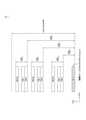
図7は、本開示の一実施例に係る、BWPの一例を示す。図7の実施例は、本開示の多様な実施例と結合されることができる。図7の実施例において、BWPは、3個と仮定する。 FIG. 7 shows an example of BWP according to an embodiment of the present disclosure. The examples of FIG. 7 can be combined with the various examples of the present disclosure. In the embodiment of FIG. 7, it is assumed that the number of BWPs is three.
図7を参照すると、CRB(common resource block)は、キャリアバンドの一側端から他側端まで番号が付けられたキャリアリソースブロックである。そして、PRBは、各BWP内で番号が付けられたリソースブロックである。ポイントAは、リソースブロックグリッド(resource block grid)に対する共通参照ポイント(common reference point)を指示することができる。 Referring to FIG. 7, a CRB (comon resource block) is a carrier resource block numbered from one side end to the other side end of a carrier band. The PRB is a numbered resource block within each BWP. Point A can indicate a common reference point for the resource block grid.
BWPは、ポイントA、ポイントAからのオフセット(NstartBWP)及び帯域幅(NsizeBWP)により設定されることができる。例えば、ポイントAは、全てのヌメロロジー(例えば、該当キャリアでネットワークによりサポートされる全てのヌメロロジー)のサブキャリア0が整列されるキャリアのPRBの外部参照ポイントである。例えば、オフセットは、与えられたヌメロロジーで最も低いサブキャリアとポイントAとの間のPRB間隔である。例えば、帯域幅は、与えられたヌメロロジーでPRBの個数である。 The BWP can be set by point A, offset from point A (NstartBWP) and bandwidth (NsizeBWP). For example, point A is the external reference point of the PRB of the carrier to which
以下、V2XまたはSL通信に対して説明する。 Hereinafter, V2X or SL communication will be described.
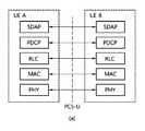
図8は、本開示の一実施例に係る、SL通信のための無線プロトコル構造(radio protocol architecture)を示す。図8の実施例は、本開示の多様な実施例と結合されることができる。具体的に、図8の(a)は、ユーザ平面プロトコルスタックを示し、図8の(b)は、制御平面プロトコルスタックを示す。 FIG. 8 shows a radio protocol architecture for SL communication according to an embodiment of the present disclosure. The examples of FIG. 8 can be combined with the various examples of the present disclosure. Specifically, FIG. 8A shows a user plane protocol stack, and FIG. 8B shows a control plane protocol stack.
以下、SL同期信号(Sidelink Synchronization Signal、SLSS)及び同期化情報について説明する。 Hereinafter, SL synchronization signals (Sidelink Synchronization Signal, SLSS) and synchronization information will be described.
SLSSは、SL特定的なシーケンス(sequence)であって、PSSS(Primary Sidelink Synchronization Signal)と、SSSS(Secondary Sidelink Synchronization Signal)とを含むことができる。前記PSSSは、S-PSS(Sidelink Primary Synchronization Signal)と称し、前記SSSSは、S-SSS(Sidelink Secondary Synchronization Signal)と称することができる。例えば、長さ-127M-シーケンス(length-127 M-sequences)がS-PSSに対して使われることができ、長さ-127ゴールド-シーケンス(length-127 Gold sequences)がS-SSSに対して使われることができる。例えば、端末は、S-PSSを利用して最初信号を検出(signal detection)することができ、同期を取得することができる。例えば、端末は、S-PSS及びS-SSSを利用して細部同期を取得することができ、同期信号IDを検出することができる。 The SLSS is an SL specific sequence and can include a PSSS (Primary Sidelink Synchronization Signal) and an SSSS (Secondy Sidelink Synchronization Signal). The PSSS can be referred to as S-PSS (Siderink Precision System Synchronization Signal), and the SSSS can be referred to as S-SSS (Siderink Precision Synchronization Signal). For example, a length-127M-sequence can be used for S-PSS and a length-127 gold-sequence can be used for S-SSS. Can be used. For example, the terminal can detect the signal (signal detection) at the beginning by using S-PSS, and can acquire the synchronization. For example, the terminal can acquire detailed synchronization using S-PSS and S-SSS, and can detect the synchronization signal ID.
PSBCH(Physical Sidelink Broadcast Channel)は、SL信号の送受信前に端末が真っ先に知るべき基本となる(システム)情報が送信される(放送)チャネルである。例えば、基本となる情報は、SLSSに対する情報、デュプレックスモード(Duplex Mode、DM)、TDD UL/DL(Time Division Duplex Uplink/Downlink)の構成、リソースプールに対する情報、SLSSに対するアプリケーションの種類、サブフレームオフセット、放送情報などである。例えば、PSBCH性能の評価のために、NR V2Xで、PSBCHのペイロード大きさは、24ビットのCRCを含んで56ビットである。 PSBCH (Physical Sidelink Broadcast Channel) is a (broadcasting) channel through which basic (system) information that a terminal should first know before transmitting and receiving SL signals is transmitted. For example, the basic information is information for SLSS, duplex mode (DM), TDD UL / DL (Time Division Duplex Uplink / Downlink) configuration, information for resource pool, application type for SLSS, subframe offset. , Broadcast information, etc. For example, for evaluation of PSBCH performance, in NR V2X, the payload size of PSBCH is 56 bits including 24-bit CRC.
S-PSS、S-SSS、及びPSBCHは、周期的送信をサポートするブロックフォーマット(例えば、SLSS(Synchronization Signal)/PSBCHブロック、以下、S-SSB(Sidelink-Synchronization Signal Block ))に含まれることができる。前記S-SSBは、キャリア内のPSCCH(Physical Sidelink Control Channel)/PSSCH(Physical Sidelink Shared Channel)と同じヌメロロジー(即ち、SCS及びCP長さ)を有することができ、送信帯域幅は、(あらかじめ)設定されたSL BWP(Sidelink Bandwidth Part)内にある。例えば、S-SSBの帯域幅は、11RB(Resource Block)である。例えば、PSBCHは、11RBにわたっている。そして、S-SSBの周波数位置は、(あらかじめ)設定されることができる。したがって、端末は、キャリアでS-SSBを見つけるために周波数で仮設検出(hypothesis detection)を実行する必要がない。 S-PSS, S-SSS, and PSBCH may be included in a block format that supports periodic transmission (for example, SLSS (Synchronization Signal) / PSBCH block, hereinafter, S-SSB (Sidelink-Synchronization Signal Block)). can. The S-SSB can have the same numerology (ie, SCS and CP length) as the PSCCH (Physical Sidelink Control Channel) / PSCH (Physical Sidelink Shared Channel) in the carrier, and the transmission bandwidth is (previously). It is in the set SL BWP (Siderink Bandwidth Part). For example, the bandwidth of S-SSB is 11 RB (Resource Block). For example, PSBCH spans 11 RB. Then, the frequency position of S-SSB can be set (in advance). Therefore, the terminal does not need to perform hypothesis detection at frequency to find the S-SSB in the carrier.
図9は、本開示の一実施例に係る、V2XまたはSL通信を実行する端末を示す。図9の実施例は、本開示の多様な実施例と結合されることができる。 FIG. 9 shows a terminal that executes V2X or SL communication according to an embodiment of the present disclosure. The examples of FIG. 9 can be combined with the various examples of the present disclosure.
図9を参照すると、V2XまたはSL通信における端末という用語は、主にユーザの端末を意味することができる。しかしながら、基地局のようなネットワーク装備が端末間の通信方式によって信号を送受信する場合、基地局も一種の端末と見なされることもできる。例えば、端末1は、第1の装置100であり、端末2は、第2の装置200である。 Referring to FIG. 9, the term terminal in V2X or SL communication can mainly mean a user's terminal. However, when network equipment such as a base station transmits and receives signals by a communication method between terminals, the base station can also be regarded as a kind of terminal. For example, the
例えば、端末1は、一連のリソースの集合を意味するリソースプール(resource pool)内で特定のリソースに該当するリソース単位(resource unit)を選択することができる。そして、端末1は、前記リソース単位を使用してSL信号を送信することができる。例えば、受信端末である端末2は、端末1が信号を送信することができるリソースプールの設定を受けことができ、前記リソースプール内で端末1の信号を検出することができる。 For example, the
ここで、端末1が基地局の連結範囲内にある場合、基地局は、リソースプールを端末1に知らせることができる。それに対して、端末1が基地局の連結範囲外にある場合、他の端末がリソースプールを知らせ、または端末1は、事前に設定されたリソースプールを使用することができる。 Here, when the
一般に、リソースプールは、複数のリソース単位で構成されることができ、各端末は、一つまたは複数のリソース単位を選定し、自分のSL信号の送信に使用することができる。 In general, a resource pool can be composed of a plurality of resource units, and each terminal can select one or a plurality of resource units and use them for transmitting its own SL signal.
以下、SLでリソース割当(resource allocation)に対して説明する。 Hereinafter, resource allocation will be described in SL.
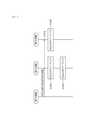
図10は、本開示の一実施例によって、端末が送信モードによってV2XまたはSL通信を実行する手順を示す。図10の実施例は、本開示の多様な実施例と結合されることができる。本開示の多様な実施例において、送信モードは、モードまたはリソース割当モードと称することができる。以下、説明の便宜のために、LTEにおいて、送信モードは、LTE送信モードと称することができ、NRにおいて、送信モードは、NRリソース割当モードと称することができる。 FIG. 10 shows a procedure in which a terminal performs V2X or SL communication depending on the transmission mode according to an embodiment of the present disclosure. The examples of FIG. 10 can be combined with the various examples of the present disclosure. In the various embodiments of the present disclosure, the transmission mode can be referred to as a mode or a resource allocation mode. Hereinafter, for convenience of explanation, in LTE, the transmission mode can be referred to as LTE transmission mode, and in NR, the transmission mode can be referred to as NR resource allocation mode.
例えば、図10の(a)は、LTE送信モード1またはLTE送信モード3と関連した端末動作を示す。または、例えば、図10の(a)は、NRリソース割当モード1と関連した端末動作を示す。例えば、LTE送信モード1は、一般的なSL通信に適用されることができ、LTE送信モード3は、V2X通信に適用されることができる。 For example, FIG. 10A shows terminal operations associated with
例えば、図10の(b)は、LTE送信モード2またはLTE送信モード4と関連した端末動作を示す。または、例えば、図10の(b)は、NRリソース割当モード2と関連した端末動作を示す。 For example, FIG. 10B shows terminal operations associated with
図10の(a)を参照すると、LTE送信モード1、LTE送信モード3またはNRリソース割当モード1で、基地局は、SL送信のために端末により使われるSLリソースをスケジューリングすることができる。例えば、基地局は、端末1にPDCCH(より具体的にDCI(Downlink Control Information))を介してリソーススケジューリングを実行することができ、端末1は、前記リソーススケジューリングによって端末2とV2XまたはSL通信を実行することができる。例えば、端末1は、PSCCH(Physical Sidelink Control Channel)を介してSCI(Sidelink Control Information)を端末2に送信した後、前記SCIに基づくデータをPSSCH(Physical Sidelink Shared Channel)を介して端末2に送信できる。 Referring to (a) of FIG. 10, in
図10の(b)を参照すると、LTE送信モード2、LTE送信モード4またはNRリソース割当モード2で、端末は、基地局/ネットワークにより設定されたSLリソースまたはあらかじめ設定されたSLリソース内でSL送信リソースを決定することができる。例えば、前記設定されたSLリソースまたはあらかじめ設定されたSLリソースは、リソースプールである。例えば、端末は、自律的にSL送信のためのリソースを選択またはスケジューリングすることができる。例えば、端末は、設定されたリソースプール内でリソースを自体的に選択し、SL通信を実行することができる。例えば、端末は、センシング(sensing)及びリソース(再)選択手順を実行し、選択ウィンドウ内で自体的にリソースを選択することができる。例えば、前記センシングは、サブチャネル単位で実行されることができる。そして、リソースプール内でリソースを自体的に選択した端末1は、PSCCHを介してSCIを端末2に送信した後、前記SCIに基づくデータをPSSCHを介して端末2に送信できる。 Referring to (b) of FIG. 10, in
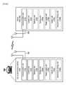
図11は、本開示の一実施例に係る、三つのキャストタイプを示す。図11の実施例は、本開示の多様な実施例と結合されることができる。具体的に、図11の(a)は、ブロードキャストタイプのSL通信を示し、図11の(b)は、ユニキャストタイプのSL通信を示し、図11の(c)は、グループキャストタイプのSL通信を示す。ユニキャストタイプのSL通信の場合、端末は、他の端末と一対一通信を実行することができる。グループキャストタイプのSL通信の場合、端末は、自分が属するグループ内の一つ以上の端末とSL通信を実行することができる。本開示の多様な実施例において、SLグループキャスト通信は、SLマルチキャスト(multicast)通信、SL一対多(one-to-many)通信などに代替されることができる。 FIG. 11 shows three cast types according to an embodiment of the present disclosure. The examples of FIG. 11 can be combined with the various examples of the present disclosure. Specifically, FIG. 11A shows broadcast type SL communication, FIG. 11B shows unicast type SL communication, and FIG. 11C shows group cast type SL communication. Indicates communication. In the case of unicast type SL communication, the terminal can execute one-to-one communication with other terminals. In the case of group cast type SL communication, the terminal can execute SL communication with one or more terminals in the group to which it belongs. In various embodiments of the present disclosure, SL group cast communication can be replaced by SL multicast communication, SL one-to-many communication, and the like.
一方、サイドリンク通信において、端末は、サイドリンク送信のためのリソースを効率的に選択する必要がある。以下、本開示の多様な実施例によって、端末がサイドリンク送信のためのリソースを効率的に選択する方法及びこれをサポートする装置に対して説明する。本開示の多様な実施例において、サイドリンク通信は、V2X通信を含むことができる。 On the other hand, in sidelink communication, the terminal needs to efficiently select resources for sidelink transmission. Hereinafter, various embodiments of the present disclosure will be used to describe a method for a terminal to efficiently select a resource for sidelink transmission and a device for supporting the method. In the various embodiments of the present disclosure, the side link communication can include V2X communication.
本開示の多様な実施例によって提案された少なくとも一つの提案方式は、ユニキャスト通信、グループキャスト通信及び/またはブロードキャスト通信のうち少なくともいずれか一つに、適用されることができる。 The at least one proposed method proposed by the various embodiments of the present disclosure can be applied to at least one of unicast communication, group cast communication and / or broadcast communication.
本開示の多様な実施例によって提案された少なくとも一つの提案方式は、PC5インターフェースまたはSLインターフェース(例えば、PSCCH、PSSCH、PSBCH、PSSS/SSSS等)ベースのサイドリンク通信またはV2X通信だけでなく、Uuインターフェース(例えば、PUSCH、PDSCH、PDCCH、PUCCH等)ベースのサイドリンク通信またはV2X通信にも、適用されることができる。 At least one proposed method proposed by the various embodiments of the present disclosure is not only PC5 interface or SL interface (eg, PSCCH, PSSCH, PSBCH, PSSS / SSSS, etc.) based side link communication or V2X communication, but also Uu. It can also be applied to interface (eg, PUSCH, PDSCH, PDCCH, PUCCH, etc.) based side link communication or V2X communication.
本開示の多様な実施例において、端末の受信動作は、サイドリンクチャネル及び/またはサイドリンク信号(例えば、PSCCH、PSSCH、PSFCH、PSBCH、PSSS/SSSS等)のデコーディング動作及び/または受信動作を含むことができる。端末の受信動作は、WAN DLチャネル及び/またはWAN DL信号(例えば、PDCCH、PDSCH、PSS/SSS等)のデコーディング動作及び/または受信動作を含むことができる。端末の受信動作は、センシング動作及び/またはCBR測定動作を含むことができる。本開示の多様な実施例において、端末のセンシング動作は、PSSCH DM-RSシーケンスベースのPSSCH-RSRP測定動作、端末が成功的にデコーディングしたPSCCHによりスケジューリングされるPSSCH DM-RSシーケンスベースのPSSCH-RSRP測定動作、S-RSSI(sidelink RSSI)測定動作、及び/またはV2Xリソースプール関連サブチャネルベースのS-RSSI測定動作を含むことができる。本開示の多様な実施例において、端末の送信動作は、サイドリンクチャネル及び/またはサイドリンク信号(例えば、PSCCH、PSSCH、PSFCH、PSBCH、PSSS/SSSS等)の送信動作を含むことができる。端末の送信動作は、WAN ULチャネル及び/またはWAN UL信号(例えば、PUSCH、PUCCH、SRS等)の送信動作を含むことができる。本開示の多様な実施例において、同期信号は、SLSS及び/またはPSBCHを含むことができる。 In the various embodiments of the present disclosure, the receiving operation of the terminal is a decoding operation and / or a receiving operation of a side link channel and / or a side link signal (for example, PSCCH, PSSCH, PSFCH, PSBCH, PSSS / SSSS, etc.). Can include. The receiving operation of the terminal can include the decoding operation and / or the receiving operation of the WAN DL channel and / or the WAN DL signal (for example, PDCCH, PDSCH, PSS / SSS, etc.). The receiving operation of the terminal can include a sensing operation and / or a CBR measurement operation. In the various embodiments of the present disclosure, the sensing operation of the terminal is a PSCH-RSRP measurement operation based on the PSCH DM-RS sequence, a PSCH DM-RS sequence-based PSCH-scheduled by the PSCCH successfully decoded by the terminal. RSRP measurement operations, S-RSSI (sidelink RSSI) measurement operations, and / or V2X resource pool-related subchannel-based S-RSSI measurement operations can be included. In the various embodiments of the present disclosure, the transmission operation of the terminal can include the transmission operation of the side link channel and / or the side link signal (for example, PSCCH, PSSCH, PSFCH, PSBCH, PSSS / SSSS, etc.). The transmission operation of the terminal can include the transmission operation of the WAN UL channel and / or the WAN UL signal (for example, PUSCH, PUCCH, SRS, etc.). In the various embodiments of the present disclosure, the sync signal can include SLSS and / or PSBCH.
本開示の多様な実施例において、設定は、シグナリング、ネットワークからのシグナリング、ネットワークからの設定、及び/またはネットワークからあらかじめ設定を含むことができる。本開示の多様な実施例において、定義は、シグナリング、ネットワークからのシグナリング、ネットワークからの設定、及び/またはネットワークからあらかじめ設定を含むことができる。本開示の多様な実施例において、指定は、シグナリング、ネットワークからのシグナリング、ネットワークからの設定、及び/またはネットワークからあらかじめ設定を含むことができる。 In various embodiments of the present disclosure, the configuration may include signaling, signaling from the network, configuration from the network, and / or pre-configuration from the network. In the various embodiments of the present disclosure, the definition can include signaling, signaling from the network, configuration from the network, and / or pre-configuration from the network. In various embodiments of the present disclosure, the designation can include signaling, signaling from the network, configuration from the network, and / or pre-configuration from the network.
本開示の多様な実施例において、PPPP(ProSe Per Packet Priority)は、PPPR(ProSe Per Packet Reliability)に代替されることができ、PPPRは、PPPPに代替されることができる。例えば、PPPP値が小さいほど高い優先順位を意味することができ、PPPP値が大きいほど低い優先順位を意味することができる。例えば、PPPR値が小さいほど高い信頼性を意味することができ、PPPR値が大きいほど低い信頼性を意味することができる。例えば、高い優先順位と関連したサービス、パケットまたはメッセージと関連したPPPP値は、低い優先順位と関連したサービス、パケットまたはメッセージと関連したPPPP値より小さい。例えば、高い信頼性と関連したサービス、パケットまたはメッセージと関連したPPPR値は、低い信頼性と関連したサービス、パケットまたはメッセージと関連したPPPR値より小さい。 In various embodiments of the present disclosure, PPPP (ProSe Per Packet Privacy) can be replaced by PPPR (ProSe Per Packet Reliability), and PPPR can be replaced by PPPP. For example, a smaller PPPP value can mean a higher priority, and a larger PPPP value can mean a lower priority. For example, a smaller PPPR value can mean higher reliability, and a larger PPPR value can mean lower reliability. For example, the PPPP value associated with a service, packet or message associated with a high priority is less than the PPPP value associated with a service, packet or message associated with a low priority. For example, a PPPR value associated with a service, packet or message associated with high reliability is less than a PPPR value associated with a service, packet or message associated with low reliability.
本開示の多様な実施例において、セッション(session)は、ユニキャストセッション(例えば、サイドリンクのためのユニキャストセッション)、グループキャスト/マルチキャストセッション(例えば、サイドリンクのためのグループキャスト/マルチキャストセッション)、及び/またはブロードキャストセッション(例えば、サイドリンクのためのブロードキャストセッション)のうち少なくともいずれか一つを含むことができる。 In the various embodiments of the present disclosure, a session is a unicast session (eg, a unicast session for a sidelink), a groupcast / multicast session (eg, a groupcast / multicast session for a sidelink). , And / or at least one of broadcast sessions (eg, broadcast sessions for sidelinks).
本開示の多様な実施例において、キャリアは、BWP及び/またはリソースプールのうち少なくともいずれか一つとして相互拡張解釈されることができる。例えば、キャリアは、BWP及び/またはリソースプールのうち少なくともいずれか一つを含むことができる。例えば、キャリアは、一つ以上のBWPを含むことができる。例えば、BWPは、一つ以上のリソースプールを含むことができる。 In the various embodiments of the present disclosure, carriers can be mutually extended as at least one of BWP and / or resource pools. For example, the carrier can include at least one of the BWP and / or the resource pool. For example, the carrier can include one or more BWPs. For example, the BWP can include one or more resource pools.
V2Xシステムにおいて、サイドリンクまたはUuリンクの送信タイプ(例えば、ブロードキャスト、グループキャスト及び/またはユニキャスト)、チャネル環境及び/またはトラフィック特性などによって、送信スキーム(scheme)(例えば、MIMO動作、HARQ-ACK/NACKフィードバックの実行可否、閉ループ(Closed-loop)TPCの実行可否、MCS tableの種類など)が異なることがあり、それによって、SCI(Sidelink Control Information)(または、制御情報)を構成するフィールドの組み合わせ及び/または各フィールドの大きさが異なることがある。互いに異なるフィールド組み合わせ及び/または各フィールドの大きさに基づくSCIは、SCIフォーマット(format)(または、制御情報フォーマット)に基づいて示すことができる。このとき、互いに異なるSCIフォーマット間のペイロードサイズ(payload size)を同じく合わせるために、少なくとも一つのパティングビット(padding bit)及び/または少なくとも一つのリザーブドビット(reserved bit)を含んでSCIフォーマットが定義されることができる。または、SCIフォーマットは、対応するパディングビット及び/またはリザーブドビットを含まずに定義されることもできる。 In a V2X system, depending on the transmission type of the side link or Uu link (eg broadcast, group cast and / or unicast), channel environment and / or traffic characteristics, etc., the transmission scheme (scheme) (eg MIMO operation, HARQ-ACK). / NACK feedback execution enablement / non-executability, closed-loop (Closed-loop) TPC execution feasibility, MCS table type, etc.) may differ, and as a result, fields that make up SCI (Siderink Control Information) (or control information) may be different. The combination and / or the size of each field may be different. SCIs based on different field combinations and / or the size of each field can be shown based on the SCI format (format) (or control information format). At this time, the SCI format is defined by including at least one padding bit and / or at least one reserved bit in order to similarly match the payload sizes (payload sizes) between different SCI formats. Can be done. Alternatively, the SCI format can be defined without the corresponding padding bits and / or reserved bits.
もし、多数のSCIフォーマットが定義され、前記多数のSCIフォーマットの各々に対するペイロードサイズ(payload size)が互いに異なる場合、端末は、各ペイロードサイズと関連してブラインドデコーディング(blind decoding)を実行すべきであり、それによって、付加的な遅延時間が要求されて電力が追加的に消耗されることができる。特に、RRCアイドル(RRC-idle)端末またはアウトオブカバレッジ(out-of-coverage)端末の場合、(既)設定された((pre)configured)SCIフォーマットに対してモニタリング(即ち、ブラインドデコーディング)を実行することができ、このとき、スケジューリングフレキシビリティ(scheduling flexibility)を考慮して多様なリソースプール(resource pool)または時間軸/周波数軸リソースで互いに異なるSCIフォーマットをモニタリングすべき場合、実行すべきブラインドデコーディング回数が増加できる。このとき、ブラインドデコーディング複雑度(complexity)を低くするための目的としてリソース使用を制限する場合、スケジューリングフレキシビリティが落ちることができ、センシングベースのサイドリンク送信を実行する時(他の送信間の衝突及び干渉(interference)によって)、送信効率が落ちることができる。 If a number of SCI formats are defined and the payload sizes for each of the many SCI formats differ from each other, the terminal should perform blind decoding in relation to each payload size. This can result in additional delay time requirements and additional power consumption. In particular, for RRC-idle or out-of-coverage terminals, monitoring (ie, blind decoding) against the (pre) configured SCI format. Should be executed if different SCI formats should be monitored for different resource pools or time / frequency axis resources in consideration of scheduling flexibility. The number of blind decodings can be increased. At this time, if resource usage is restricted for the purpose of reducing blind decoding complexity, scheduling flexibility can be reduced and when performing sensing-based side-link transmissions (between other transmissions). (Due to collisions and interference), transmission efficiency can be reduced.
したがって、前記問題を解決するために、一実施例ではSCIフォーマットが複数個定義される時、各SCIフォーマットに対するサイズを同じく調整する方法を考慮することができる。即ち、定義された複数個のSCIフォーマット毎にフィールドの構成が異なることがあるが、少なくとも一つのパディングビット及び/またはリザーブドビットを利用してSCIフォーマット相互間サイズ(または、ペイロードサイズ)を同じくすることができる。このとき、各SCIフォーマットを構成するフィールドを指示するためにフォーマットインジケータ(format indicator)がフィールド内に追加されることができ、該当フィールドの位置は、各制御情報フォーマットのフィールド構成にかかわらず一定である。前記少なくとも一つのパディングビットまたはリザーブドビットを追加する方法において、SCIフォーマット内定義されることができる全ての種類のフィールドがイネイブル(enable)された場合に基づいてSCIフォーマットのペイロードサイズが設定されることができる。もし、SCIフォーマット内の特定フィールドがデセイブル(disable)された場合、該当フィールドに対応する値を0または1に仮定し、または特定値が送信されても該当値を無視することができる。 Therefore, in order to solve the above problem, in one embodiment, when a plurality of SCI formats are defined, a method of adjusting the size for each SCI format can be considered. That is, although the field configuration may differ for each of the plurality of defined SCI formats, at least one padding bit and / or reserved bit is used to make the SCI format mutual size (or payload size) the same. can do. At this time, a format indicator (format indicator) can be added in the field to indicate the field constituting each SCI format, and the position of the corresponding field is constant regardless of the field configuration of each control information format. be. In the method of adding at least one padding bit or reserved bit, the payload size of the SCI format is set based on the case where all kinds of fields that can be defined in the SCI format are enabled. be able to. If a specific field in the SCI format is disabled, the value corresponding to the field can be assumed to be 0 or 1, or the value can be ignored even if the specific value is transmitted.
前記のようなフィールドのイネイブル/デセイブル可否は、前記フォーマットインジケータのビット値に基づいて区分されることができる。または、SCIフォーマットのフィールド組み合わせのうち最も大きいサイズで構成されるSCIフォーマットに基づいてSCIフォーマットのペイロードサイズが設定されることができる。前記最も大きいサイズで構成されるSCIフォーマットを除外した残りのSCIフォーマットに対しては、SCIのMSB(Most Significant Bit)またはLSBにパディングビットを追加し、または前記フォーマットインジケータに対するビットと実質的(actual)SCIとの間にパディングビットを追加することができる。このとき、SCIフォーマット間のフィールド構成が相互異なっても、サイドリンク送信の特性上、他の端末が活用できる情報の位置(例えば、センシングのために必要なリソース割当フィールド(resource allocation field)またはDMRSパターンインジケーションフィールド(DMRS pattern indication field)等)は固定されることができる。 The enable / disable enable / disable of the field as described above can be classified based on the bit value of the format indicator. Alternatively, the payload size of the SCI format can be set based on the SCI format, which consists of the largest of the SCI format field combinations. For the remaining SCI formats, excluding the SCI format consisting of the largest size, add a padding bit to the MSB (Most Significant Bit) or LSB of the SCI, or add a bit to the format indicator and actual. ) A padding bit can be added between the SCI and the SCI. At this time, even if the field configurations between the SCI formats are different from each other, the position of information that can be utilized by other terminals due to the characteristics of sidelink transmission (for example, the resource allocation field required for sensing or DMRS). The pattern indication field (DMRS pattern indicator field, etc.) can be fixed.
他の一実施例では、SCIフォーマットを検出するためのサーチスペース(search space)によって前記SCIフォーマットまたは(ペイロード)サイズが決定されることができる。または、SCIフォーマットの(ペイロード)サイズによって、該当SCIフォーマットが送信される制御チャネル領域が区分されることができる。 In another embodiment, the search space for detecting the SCI format can determine the SCI format or (payload) size. Alternatively, the control channel area in which the corresponding SCI format is transmitted can be divided by the (payload) size of the SCI format.
他の一実施例では、異なるSCIフォーマット間のサイズを同じく調整するために少なくとも一つのパディングビットまたは少なくとも一つのリザーブドビットを利用する場合、別途のインジケーションビットフィールド(indication bit field)の代わりにCRCに特定シーケンス(sequence)でスクランブリング(scrambling)する動作を介して、該当SCIがどのようなフォーマットで送信されたか(即ち、どのような組み合わせのフィールドで構成されたか)を示すことができる。 In another embodiment, when using at least one padding bit or at least one reserved bit to similarly adjust the size between different SCI formats, instead of a separate indication bit field. It is possible to indicate to the CRC in what format the SCI was transmitted (ie, what combination of fields it was composed of) through the action of scrambling in a specific sequence.
他の一実施例では、DMRSシーケンス生成(DMRS sequence generation)時に適用される初期化(initialization)IDがSCIフォーマット別に異なるように適用されることができる。または、プール特定(pool-specific)に最大ペイロードサイズ(maximum payload size)またはSCIフォーマットが決定されることができ、前記(ペイロードサイズ)を同じく合わせる動作は、プール特定に実行されることができる。即ち、特定プール内で許容された最も大きいペイロードサイズまたは最も大きいペイロードサイズに対応されるSCIフォーマットを基準にして各SCIフォーマットのサイズを同じく合わせることができ、このような方式は、システムに事前に定義されることができる。 In another embodiment, the initialization ID applied during DMRS sequence generation can be applied differently for each SCI format. Alternatively, the maximum payload size or SCI format can be determined for pool-specific, and the same operation of matching the payload size can be performed for pool identification. That is, the size of each SCI format can be similarly matched relative to the SCI format corresponding to the largest or largest payload size allowed in a particular pool, such a method preliminarily in the system. Can be defined.
他の一実施例において、基地局からシグナリングされた情報に基づいて、端末は、プール特定に許容可能な最大ペイロードサイズまたは最大ペイロードサイズに対応されるSCIフォーマットを(あらかじめ)設定することができ、該当SCIフォーマットを基準にして各SCIフォーマットのサイズを同じく合わせることができる。 In another embodiment, based on the information signaled from the base station, the terminal can (preliminarily) set the SCI format corresponding to the maximum payload size or maximum payload size acceptable for pool identification. The size of each SCI format can be adjusted in the same manner based on the corresponding SCI format.
他の一実施例において、サービス別に要求される信頼度(reliability)などが異なる点に基づいて、サービス特定(service-specific)にSCIフォーマットが定義され、または送信情報の優先権(priority)によってSCIフォーマットが定義されることができる。一例示において、特定サービスのために要求される要求事項(requirement)によって、SCIのペイロードサイズを減らすためにデータ送信時に適用されるリソース割当単位(例えば、サブチャネル(subchannel))が異なるように定義されることができ、前記リソース割当単位によってSCIフォーマットの(ペイロード)サイズが決定されることができる。または、CBR(Channel Busy Ratio)レベル(level)によってSCIフォーマットが定義されることができる。例えば、高い混雑レベル(high congestion level)では、よりコンパック(compact)な情報(または、より少ないサイズのSCI)で構成されたSCIフォーマットを使用するように定義されることができる。このとき、各サービス、送信情報の優先権及び/または混雑レベル(congestion level)によって定義される一つ以上のSCIフォーマット間(ペイロード)のサイズを同じく合わせる動作を適用することができ、ペイロードサイズを同じく合わせるための具体的な動作は、前述した実施例と同一/類似する。 In another embodiment, the SCI format is defined for service-specific based on the difference in reliability and the like required for each service, or SCI is defined by the priority of transmitted information. The format can be defined. In one example, it is defined that the resource allocation unit (for example, subchannel) applied at the time of data transmission in order to reduce the payload size of SCI differs depending on the requirement required for a specific service. The resource allocation unit can determine the (payload) size of the SCI format. Alternatively, the SCI format can be defined by the CBR (Cannel Busy Ratio) level (level). For example, at a high connection level, it can be defined to use an SCI format composed of more compact information (or less sized SCI). At this time, it is possible to apply the operation of matching the size of one or more SCI formats (payload) defined by each service, the priority of transmission information and / or the congestion level, and the payload size. The specific operation for matching is the same as / similar to the above-described embodiment.
前記実施例のように、SCIフォーマット間のサイズを同じく合わせるために特定SCIフォーマットに少なくとも一つのパディングビットまたは少なくとも一つのリザーブドビットを追加する場合、該当ビットを事前に定義された値(例えば、0または1)に基づいて送信することで仮想CRC(virtual CRC)として活用することもでき、または付加的な情報を送信するためのフィールドとして使用することもできる。付加的な情報は、例えば、センシング動作を容易にする情報(例えば、該当SCIに連動されたデータ送信が周期的(periodic)送信かまたは非周期的(aperiodic)送信かに対する情報、該当データ送信が周期的送信である場合において、今後残っているリソース留保(reservation)個数に対する情報等)を含むことができる。 When adding at least one padding bit or at least one reserved bit to a particular SCI format to match the same size between SCI formats as in the above embodiment, the corresponding bit is a predefined value (eg, for example). It can be used as a virtual CRC (virtual CRC) by transmitting based on 0 or 1), or it can be used as a field for transmitting additional information. The additional information is, for example, information for facilitating the sensing operation (for example, information on whether the data transmission linked to the SCI is periodic or aperiodic transmission, and the relevant data transmission is possible. In the case of periodic transmission, information on the number of resource reservations remaining in the future) can be included.
一方、以下、図12では前記フォーマットインジケータを具現するための具体化された実施例に対して記述する。 On the other hand, in FIG. 12, a specific embodiment for embodying the format indicator will be described below.
図12は、本開示の一実施例に係る、フォーマットインジケータに基づいて制御情報フォーマットを決定する方法を示す。 FIG. 12 shows a method of determining a control information format based on a format indicator according to an embodiment of the present disclosure.
一実施例において、フォーマットインジケータ(format indicator)は、ヘッダ(header)情報とも呼ばれる(または、示される)。前記フォーマットインジケータまたは前記ヘッダ情報は、SCIフォーマット内で別途のフィールドに定義されることもできるが、間接的な(または、暗黙的な)方法にインジケート(indicate)されることもできる。一例示において、DMRSにモジュレーション(modulation)シンボルを掛ける方式を介して前記フォーマットインジケータまたは前記ヘッダ情報がインジケートされることができる。他の一例示では、DMRSのシーケンスを異なるように(例えば、CS(Cyclic Shift)値を異なるように)送信することによって前記フォーマットインジケータまたは前記ヘッダ情報がインジケートされることができる。 In one embodiment, the format indicator is also referred to (or indicated) as header information. The format indicator or the header information can be defined in a separate field within the SCI format, but can also be indicated in an indirect (or implicit) way. In one example, the format indicator or the header information can be encoded via a method of multiplying the DMRS with a modulation symbol. In another example, the format indicator or header information can be encoded by transmitting different DMRS sequences (eg, different CS (Cyclic Shift) values).
前記一実施例のように、DMRSのCSを利用したりモジュレーションシンボルを利用したりしてシーケンスディテクション(sequence detection)に基づいて(ペイロード)サイズまたはSCIフォーマットが間接的に(または、暗黙的に)決定される場合、装置(または、端末)のブラインドデコーディング試み回数が減少されることができる。SCIフォーマットと前記モジュレーションシンボルまたはシーケンスのCS値間の関係は、システムに(事前に)定義され、または基地局が端末に上位階層シグナリング(higher layer signalling)及び/または物理階層シグナリング(physical layer signaling)を介して関連情報を伝達することによって設定されることができる。 As in the above embodiment, the (payload) size or SCI format is indirectly (or implicitly) based on sequence detection by utilizing the CS of DMRS or the modulation symbol. ) If determined, the number of blind decoding attempts at the device (or terminal) can be reduced. The relationship between the SCI format and the CS value of the modulation symbol or sequence is defined in the system (in advance), or the base station sends the terminal to higher layer signaling and / or physical layer signaling. It can be set by transmitting relevant information via.
図12を参照すると、装置(または、端末)がDMRSのCSに基づいて(ペイロード)サイズまたはSCIフォーマットを決定する方法の一例示が示されている。一実施例に係る装置は、ステップS1210において、DMRSシーケンスCSとSCIフォーマットとの間の関係を(事前に)設定することができる。ステップS1220において、装置は、CS j=0のDMRSシーケンスに基づいてSCIに対するデコーディングを試みることができる。ステップS1230において、装置は、CS j=0が対応SCIのDMRSシーケンスに適用されるかどうかを判断(または、決定)することができる。CS j=0が対応SCIのDMRSシーケンスに適用されないという決定に基づいて、ステップS1240において、装置は、可用なjが全てチェックされたかどうかを判断することができる。可用なjが全てチェックされなかったという決定に基づいて、j=0に1が加算されてj=1になることができる。再び、ステップS1230に戻って、装置は、CS j=1が対応SCIのDMRSシーケンスに適用されるかどうかを判断(または、決定)することができる。前記ステップS1230乃至S1250が順に繰り返しされながら、jが0から1ずつ増加しながらCS jが順にチェックされることができる。もし、ステップS1230において、CS jが対応SCIのDMRSシーケンスに適用されると判断された場合、ステップS1260に進行し、装置は、デコーディングのためのSCIフォーマットを、CS jに対応されるSCIフォーマットに決定できる。一方、jが0から1ずつ増加しながら可用なCS jが順に全てチェックされたにもかかわらず、対応SCIのDMRSシーケンスに適用されるCS jを検出することができない場合、ステップS1270に進行し、装置は、SCIに対するデコーディングに失敗したと判断(または、決定)できる。 Referring to FIG. 12, an example of how the device (or terminal) determines the (payload) size or SCI format based on the CS of DMRS is shown. The apparatus according to one embodiment can set (in advance) the relationship between the DMRS sequence CS and the SCI format in step S1210. In step S1220, the device can attempt decoding for SCI based on the DMRS sequence with CS j = 0. In step S1230, the apparatus can determine (or determine) whether CS j = 0 applies to the DMRS sequence of the corresponding SCI. Based on the determination that CS j = 0 does not apply to the DMRS sequence of the corresponding SCI, in step S1240 the device can determine if all available j have been checked. Based on the determination that all available js have not been checked, 1 can be added to j = 0 to give j = 1. Returning to step S1230 again, the apparatus can determine (or determine) whether CS j = 1 applies to the DMRS sequence of the corresponding SCI. While the steps S1230 to S1250 are repeated in order, CS j can be checked in order while j increases by 1 from 0. If, in step S1230, it is determined that CS j applies to the DMRS sequence of the corresponding SCI, the process proceeds to step S1260, where the apparatus converts the SCI format for decoding into the SCI format corresponding to CS j. Can be decided. On the other hand, if it is not possible to detect CS j applied to the DMRS sequence of the corresponding SCI even though all available CS js are checked in order while j increases by 1 from 0, the process proceeds to step S1270. , The device can determine (or determine) that decoding for SCI has failed.
図13は、本開示の一実施例に係る、複数の装置間のサイドリンク通信方法を示す。より具体的に、図13は、装置(図13の第1の装置)が外部装置(図13の第2の装置及び/または第3の装置)にSCIを2ステップ(2-stage)に送信する方法の一例示を示す。 FIG. 13 shows a side link communication method between a plurality of devices according to an embodiment of the present disclosure. More specifically, in FIG. 13, the device (first device in FIG. 13) transmits SCI to an external device (second device and / or third device in FIG. 13) in two steps (2-stage). An example of how to do this is shown.
本開示において、“2ステップSCI送信”は、2ステップ送信、2-ステージ送信、2-ステージSCI送信など、多様な用語に代替されることができ、前記2ステップSCI送信で、先に送信される“第1のSCI”は、第1のサイドリンク制御情報、第1の制御情報など、多様な用語に代替されることができ、後に送信される“第2のSCI”は、第2のサイドリンク制御情報、第2の制御情報など、多様な用語に代替されることができる。前記第1のSCIは、前記第2のSCIに対する情報を含むことができる。また、“SCIフォーマット”は、制御情報フォーマット、サイドリンク制御情報フォーマットなど、多様な用語に代替されることができる。 In the present disclosure, "2-step SCI transmission" can be replaced with various terms such as 2-step transmission, 2-stage transmission, 2-stage SCI transmission, etc., and is transmitted first in the 2-step SCI transmission. The "first SCI" can be replaced with various terms such as the first side link control information and the first control information, and the "second SCI" transmitted later is the second. It can be replaced with various terms such as side link control information and second control information. The first SCI can include information for the second SCI. Further, the "SCI format" can be replaced with various terms such as a control information format and a side link control information format.
本開示では相互間にSL通信を実行する二つの装置(または、端末)のうち、最初にPSSCH(Physical Sidelink Shared Channel)及び/またはPSCCH(Physical Sidelink Control Channel)を送信する装置を“第1の装置”と示し、前記PSSCH及び/またはPSCCHを受信する装置を“第2の装置”及び/または“第3の装置”と示している。本開示において、前記第1の装置は、送信端末、転送端末、送信装置、TX UE、転送UE、送信UE、transmitter UE、UEなど、多様な用語に代替されることができ、前記第2の装置及び/または第3の装置は、受信端末、RX UE、受信UE、receiver UE、UEなど、多様な用語に代替されることができる。 In the present disclosure, of the two devices (or terminals) that execute SL communication between each other, the device that first transmits the PSCH (Physical Sidelink Shared Channel) and / or the PSCCH (Physical Sidelink Control Channel) is referred to as the “first device”. The device that receives the PSCH and / or PSCCH is referred to as a "second device" and / or a "third device". In the present disclosure, the first device can be replaced with various terms such as a transmission terminal, a transfer terminal, a transmission device, a TX UE, a transfer UE, a transmission UE, a transmitter UE, a UE, and the like. The device and / or the third device can be replaced with various terms such as a receiving terminal, an RX UE, a receiving UE, a receiver UE, and a UE.
より具体的に分類すると、前記第2の装置は、前記第2のSCIのターゲットになる装置(または、端末)を示す“ターゲット装置”と呼ばれ、前記第3の装置は、前記第2のSCIのターゲットにならない装置(または、端末)を示す“ターゲット外(non-target)装置”と呼ばれる。 More specifically, the second device is called a "target device" indicating a device (or terminal) to be a target of the second SCI, and the third device is the second device. It is called a "non-target device" that indicates a device (or terminal) that is not a target of SCI.
また、‘第1の装置’と‘第2の装置及び/または第3の装置’は、PSSCH及び/またはPSCCHを送信するかまたは受信するかなどに基づいて分類されるため、当該技術分野の通常の技術者は、時間が経過するにつれて前記‘第1の装置’が前記‘第2の装置及び/または第3の装置’に転換されることができ、前記‘第2の装置及び/または第3の装置’が前記‘第1の装置’に転換可能であることを容易に理解することができる。 Further, since the'first device'and the'second device and / or third device'are classified based on whether the PSCH and / or the PSCCH is transmitted or received, etc. An ordinary technician can convert the'first device'to the'second device and / or the third device' over time, and the'second device and / or It can be easily understood that the'third device'is convertible to the'first device'.
一実施例に係る第1の装置は、ステップS1310において、PSCCH及び/またはPSSCHを第2の装置及び/または第3の装置に送信することができる。このとき、前記PSCCH及び/または前記PSSCHは、前記第1の装置から前記第2の装置及び/または前記第3の装置に、図11で前述されたユニキャストタイプのSL通信、グループキャストタイプのSL通信及び/またはブロードキャストタイプのSL通信に基づいて送信されることができる。 The first apparatus according to one embodiment can transmit the PSCCH and / or the PSCH to the second apparatus and / or the third apparatus in step S1310. At this time, the PSCCH and / or the PSSCH is the unicast type SL communication and group cast type described in FIG. 11 from the first device to the second device and / or the third device. It can be transmitted based on SL communication and / or broadcast type SL communication.
一実施例に係る第2の装置(ターゲット装置)は、ステップS1320で前記PSCCHをデコーディングすることができ、ステップS1330で前記PSSCHをデコーディングすることができる。一例示において、第2の装置(ターゲット装置)は、前記PSCCHを介して送信される前記第1のSCIをデコーディングすることができ、前記第1のSCIに対するデコーディング結果に基づいて、前記PSSCHを介して送信される前記第2のSCIをデコーディングすることができ、前記第1のSCI及び/または前記第2のSCIに対するデコーディング結果に基づいて、前記PSSCHをデコーディングすることに決定できる。 The second device (target device) according to one embodiment can decode the PSCCH in step S1320 and can decode the PSCCH in step S1330. In one example, the second device (target device) can decode the first SCI transmitted via the PSCCH, and based on the decoding result for the first SCI, the PSCH The second SCI transmitted via can be decoded, and the PSCH can be determined to be decoded based on the decoding result for the first SCI and / or the second SCI. ..
一実施例に係る第3の装置(ターゲット外装置)は、ステップS1340で前記PSCCHをデコーディングすることができる。このとき、第3の装置は、前記PSSCHをデコーディングしないことを特徴とする。一例示において、第3の装置(ターゲット外装置)は、前記PSCCHを介して送信される前記第1のSCIをデコーディングすることができ、前記第1のSCIに対するデコーディング結果に基づいて、前記PSSCHを介して送信される前記第2のSCIをデコーディングすることができ、前記第1のSCI及び/または前記第2のSCIに対するデコーディング結果に基づいて、前記PSSCHをデコーディングしないことに決定できる。 The third device (non-target device) according to one embodiment can decode the PSCCH in step S1340. At this time, the third device is characterized in that the PSSCH is not decoded. In one example, the third device (non-target device) can decode the first SCI transmitted via the PSCCH, and based on the decoding result for the first SCI, the said. It is possible to decode the second SCI transmitted via the PSCH and decide not to decode the PSCH based on the decoding result for the first SCI and / or the second SCI. can.
以下では第1のSCI及び第2のSCIと関連してより具体的に検討する。 In the following, we will consider more specifically in relation to the first SCI and the second SCI.
一例示において、第1のSCIが含む情報の例示は、以下の表5の通りである。 In one example, an example of the information contained in the first SCI is shown in Table 5 below.

他の一例示において、第1のSCIが含む情報の例示は、以下の表6の通りである。 In another example, an example of the information contained in the first SCI is shown in Table 6 below.

他の一例示において、第1のサイドリンク制御情報(1st SCI)が含む情報の例示は、以下の表7の通りである。 In another example, the example of the information included in the first side link control information (1st SCI) is as shown in Table 7 below.

第1のSCIの場合、装置(または、端末)区分無しで全ての装置(または、端末)が検出可能に構成されることができる。装置区分無しで全ての装置が検出可能に構成される場合、前記第1のSCIに後続する第2のSCIがターゲットとするターゲット装置(または、ターゲット端末)でない、ターゲット外(non-target)装置が前記第1のSCIを介して検出された情報に基づいて、前記ターゲット装置が使用中であるリソースをセンシングすることを容易にすることができる(そのために、例えば、第1のSCIは、サイドリンク送信に利用される時間軸/周波数軸リソース情報を含むことができる)。 In the case of the first SCI, all devices (or terminals) can be configured to be detectable without device (or terminal) classification. A non-target device that is not the target device (or target terminal) targeted by the second SCI following the first SCI when all devices are configured to be detectable without device classification. Can facilitate sensing of resources in use by the target device based on the information detected via the first SCI (for which, for example, the first SCI is a side). Time axis / frequency axis resource information used for link transmission can be included).
このとき、前記ターゲット装置は、第1のSCIを検出した以後、第2のSCIを受信(または、デコーディング)する必要があり、そのために、第1のSCIは、第2のSCIを検出するための情報を含むことができる。一例示において、第1のSCIは、第2のSCIのSCIフォーマットに対する情報(例えば、ペイロードサイズに対する情報または送信モード(transmission mode)に対する情報等)を含むことができる。その他、第1のSCIは、第2のSCIのサイズ、送信されるチャネル情報、リソース情報及び/またはコードレート情報(または、コードレーティング情報)などを含むことができる。 At this time, the target device needs to receive (or decode) the second SCI after detecting the first SCI, and therefore, the first SCI detects the second SCI. Can contain information for. By way of example, the first SCI can include information about the SCI format of the second SCI, such as information about the payload size or information about the transmission mode. In addition, the first SCI can include the size of the second SCI, channel information to be transmitted, resource information and / or code rate information (or code rating information) and the like.
他の一例示において、または前記一例示と結合することで、第1のSCIは、ペイロード内にターゲット装置またはターゲットグループのIDを含んだまま送信されることができ、第2のSCIを処理するにあたって、前記IDに基づいてCRCスクランブリングを実行することができる。第1のSCIがデスティネーションID(destination ID)または第2のSCIのターゲットになるターゲット装置に対する情報を含む場合、第1のSCIのペイロードサイズが増加されることができるが、ターゲット装置を除外したターゲット外装置により実行される第2のSCIに対する不必要なデコーディングを防止することができる。それと違って、デスティネーションIDまたはターゲット装置に対する情報を第2のSCIに含み、またはCRCスクランブリングを介して反映する場合、第1のSCIのペイロードサイズを減らすことができるが、ターゲット外装置が不必要に第2のSCIに対するデコーディングを実行しなければならない。第2のSCIには、前記第2のSCIがどのような第1のSCIに対応されるかを確認(verification)するための情報が含まれることができ、第1のSCIで指示した構成情報によってMIMO関連パラメータ、CBGTI(CBG Transmission Information)、HARQ-ACKフィードバック関連情報などが含まれることができる。 In another example, or in combination with the above example, the first SCI can be transmitted with the ID of the target device or target group included in the payload and processes the second SCI. In order to do so, CRC scrambling can be executed based on the ID. If the first SCI contains information about the destination ID or the target device targeted by the second SCI, the payload size of the first SCI can be increased, but the target device is excluded. Unnecessary decoding of the second SCI performed by the off-target device can be prevented. In contrast, if the destination ID or information about the target device is included in the second SCI or reflected via CRC scrambling, the payload size of the first SCI can be reduced, but the off-target device is not. Decoding for the second SCI must be performed if necessary. The second SCI can include information for confirming what kind of first SCI the second SCI corresponds to, and the configuration information specified in the first SCI. It can include MIMO-related parameters, CBGTI (CBG Transition Information), HARQ-ACK feedback-related information, and the like.
図14は、本開示の一実施例に係る第1の装置の動作を示す流れ図である。 FIG. 14 is a flow chart showing the operation of the first device according to the embodiment of the present disclosure.
図14の流れ図に開示された動作は、本開示の多様な実施例と結合して実行されることができる。一例示において、図14の流れ図に開示された動作は、図16乃至図21に示す装置のうち少なくとも一つに基づいて実行されることができる。他の一例示において、図14の流れ図に開示された動作は、図13の流れ図に開示された動作と多様な方式に結合されて実行されることができる。一例示において、図14の第1の装置は、後述される図17の第1の無線機器100と対応されることができる。他の一例示において、図14の第1の装置は、後述される図17の第2の無線機器200と対応されることができる。 The operation disclosed in the flow chart of FIG. 14 can be performed in combination with the various embodiments of the present disclosure. By way of example, the operation disclosed in the flow chart of FIG. 14 can be performed based on at least one of the devices shown in FIGS. 16 to 21. In another example, the operation disclosed in the flow chart of FIG. 14 can be combined with the operation disclosed in the flow chart of FIG. 13 and performed in various ways. In one example, the first device of FIG. 14 can correspond to the
ステップS1410において、一実施例に係る第1の装置は、PSCCH(Physical Sidelink Control Channel)を介して第1のSCI(Sidelink Control Information)を第2の装置に送信することができる。一例示において、前記第1の制御情報は、前記PSCCHを介して、ブロードキャストタイプのSL通信、ユニキャストタイプのSL通信及び/またはグループキャストタイプのSL通信に基づいて、前記第1の装置から前記第2の装置に送信されることができる。 In step S1410, the first device according to one embodiment can transmit the first SCI (Sidelink Control Information) to the second device via the PSCCH (Physical Sidelink Control Channel). In an example, the first control information is transmitted from the first device to the first device based on broadcast type SL communication, unicast type SL communication and / or group cast type SL communication via the PSCCH. It can be transmitted to a second device.
ステップS1420において、一実施例に係る第1の装置は、前記PSCCHと関連したPSSCH(Physical Sidelink Shared Channel)を介して第2のSCIを前記第2の装置に送信することができる。一例示において、前記第1の制御情報は、前記第2の制御情報に対する情報を含むことができる。 In step S1420, the first device according to one embodiment can transmit the second SCI to the second device via the PSCH (Physical Sidelink Shared Channel) associated with the PSCCH. In one example, the first control information can include information for the second control information.
一実施例において、前記第1のSCIは、前記第2のSCIのリソースに対する情報を含むことができる。 In one embodiment, the first SCI can include information about the resources of the second SCI.
一実施例において、前記第2のSCIのリソースに対する前記情報は、前記第2のSCIがマッピングされるRE(Resource Element)の個数及びコーディングレート(coding rate)に対する情報、前記第2のSCIがマッピングされる前記REの個数に対する情報または前記コーディングレートに対する情報を含むことができる。 In one embodiment, the information for the resource of the second SCI is the information for the number of REs (Resource Elements) to which the second SCI is mapped and the coding rate, and the information for the coding rate is mapped to the second SCI. Information on the number of REs to be made or information on the coding rate can be included.
一実施例において、前記第2のSCIがマッピングされる前記REの個数及び前記コーディングレートに対する前記情報は、ベータオフセット(beta offset)に対する情報を含むことができる。 In one embodiment, the information for the number of REs and the coding rate to which the second SCI is mapped can include information for a beta offset.
一実施例において、前記ベータオフセットに対する情報は、前記ベータオフセットを指示するためのベータオフセットインジケータ(beta offset indicator)を含むことができる。 In one embodiment, the information for the beta offset can include a beta offset indicator to indicate the beta offset.
一実施例において、前記第2のSCIのリソースに対する前記情報は、アグリゲーションレベル(aggregation level)に対する情報をさらに含むことができる。 In one embodiment, the information for the resource of the second SCI can further include information for the aggregation level.
一実施例において、前記第2のSCIのリソースに対する前記情報は、2ビットで表示されることができる。 In one embodiment, the information for the resource of the second SCI can be displayed in 2 bits.
一実施例において、前記第1のSCIは、前記PSSCHの時間または周波数リソースに対する情報、前記PSSCHのデコーディングに必要なMCS(Modulation and Coding Scheme)情報または前記PSSCH上のデータに対するプライオリティ(priority)情報のうち少なくとも一つを含むことができる。 In one embodiment, the first SCI is information about the time or frequency resource of the PSCH, MCS (Modulation and Coding Scene) information required for decoding the PSCH, or priority information for data on the PSCH. At least one of them can be included.
一実施例において、前記第2のSCIは、前記PSSCH上のデータに対するソースID(SOURCE ID)またはデスティネーションID(DESTINATION ID)に対する情報、HARQ(Hybrid Automatic Repeat Request)プロセスID(HARQ PROCESS ID)情報またはNDI(New Data Indicator)またはRV(Redundancy Version)のうち少なくとも一つを含むことができる。 In one embodiment, the second SCI is information for a source ID (SOURCE ID) or a destination ID (DESTITION ID) for data on the PSCH, and HARQ (Hybrid Automatic Repeat Request) process ID (HARQ PROCESS ID) information. Alternatively, at least one of NDI (New Data Indicator) or RV (Redundancy Version) can be included.
一実施例において、前記第1のSCIを送信するためのリソース領域と、前記第2のSCIを送信するためのリソース領域は、相互オーバーラップされない。一例示において、PSCCHに対するリソース内でシグナリングされる第1の制御情報と、PSSCHに対するリソース内でシグナリングされる第2の制御情報は、相互オーバーラップされない。 In one embodiment, the resource area for transmitting the first SCI and the resource area for transmitting the second SCI do not overlap each other. In one example, the first control information signaled within the resource for PSCCH and the second control information signaled within the resource for PSCH do not overlap each other.
一実施例において、前記第2の装置により実行される前記第1のSCIと前記第2のSCIに対するデコーディング結果に基づいて、前記PSSCHが前記第2の装置によりデコーディングされることができる。例えば、前記第2の装置により実行される前記第1のSCIと前記第2のSCIに対するデコーディング結果に基づいて、前記PSSCH上のデータが前記第2の装置によりデコーディングされることができる。即ち、前記第2の装置により実行される前記第1のSCIと前記第2のSCIに対するデコーディングの結果に基づいて、前記第2の装置はターゲット装置に決定されることができる。 In one embodiment, the PSCH can be decoded by the second device based on the decoding results for the first SCI and the second SCI performed by the second device. For example, data on the PSSCH can be decoded by the second device based on the decoding results for the first SCI and the second SCI performed by the second device. That is, the second device can be determined as the target device based on the result of decoding for the first SCI and the second SCI performed by the second device.
一実施例において、前記第1のSCIは、前記PSCCHを介して第3の装置に送信されることができ、前記第3の装置により実行される前記第1のSCIと前記第2のSCIに対するデコーディング結果に基づいて、前記PSSCHが前記第3の装置によりデコーディングされない。例えば、前記第1のSCIは、前記PSCCHを介して第3の装置に送信されることができ、前記第3の装置により実行される前記第1のSCIと前記第2のSCIに対するデコーディング結果に基づいて、前記PSSCH上のデータが前記第3の装置によりデコーディングされない。即ち、前記第3の装置により実行される前記第1のSCIと前記第2のSCIに対するデコーディング結果に基づいて、前記第3の装置は、ターゲット外(non-target)装置に決定されることができる。 In one embodiment, the first SCI can be transmitted to a third device via the PSCCH for the first SCI and the second SCI performed by the third device. Based on the decoding result, the PSCH is not decoded by the third device. For example, the first SCI can be transmitted to the third device via the PSCCH, and the decoding result for the first SCI and the second SCI executed by the third device. Based on, the data on the PSSCH is not decoded by the third device. That is, the third device is determined to be a non-target device based on the decoding results for the first SCI and the second SCI performed by the third device. Can be done.
本開示の一実施例によって、SL通信を実行する第1の装置が提供されることができる。前記第1の装置は、命令語を格納する少なくとも一つのメモリ(at least one memory)、少なくとも一つの送受信機(at least one transceiver)、及び前記少なくとも一つのメモリと前記少なくとも一つの送受信機を連結する少なくとも一つのプロセッサ(at least one processor)を含み、前記少なくとも一つのプロセッサは、前記少なくとも一つの送受信機がPSCCH(Physical Sidelink Control Channel)を介して第1のSCI(Sidelink Control Information)を第2の装置に送信するように制御し、前記少なくとも一つの送受信機が前記PSCCHと関連したPSSCH(Physical Sidelink Shared Channel)を介して第2のSCIを前記第2の装置に送信するように制御し、前記第1のSCIは、前記第2のSCIのリソースに対する情報を含むことを特徴とする。 According to one embodiment of the present disclosure, a first device for performing SL communication can be provided. The first device connects at least one memory (at least one memory) for storing command words, at least one transceiver (at least one transceiver), and the at least one memory and the at least one transceiver. The at least one processor includes a first SCI (Siderink Control Information) via a PSCCH (Physical Sidelink Control Channel). The device is controlled to transmit the second SCI to the device, and the at least one transceiver is controlled to transmit the second SCI to the second device via the PSCH (Physical Sidelink Shared Channel) associated with the PSCCH. The first SCI is characterized by including information about the resources of the second SCI.
本開示の一実施例によると、第1の端末を制御する装置(または、チップ(セット))が提供されることができる。前記装置は、少なくとも一つのプロセッサ(at least one processor)及び前記少なくとも一つのプロセッサにより実行可能に連結され、命令語を格納する少なくとも一つのメモリ(at least one computer memory)を含み、前記少なくとも一つのプロセッサが前記命令語を実行することによって、前記第1の端末は:PSCCH(Physical Sidelink Control Channel)を介して第1のSCI(Sidelink Control Information)を第2の装置に送信し、前記PSCCHと関連したPSSCH(Physical Sidelink Shared Channel)を介して第2のSCIを前記第2の装置に送信し、前記第1のSCIは、前記第2のSCIのリソースに対する情報を含むことを特徴とする。 According to one embodiment of the present disclosure, a device (or chip (set)) for controlling a first terminal can be provided. The device includes at least one processor (at least one processor) and at least one memory (at least one computer memory) operably linked by the at least one processor and storing an instruction word, and the at least one of the above. When the processor executes the instruction word, the first terminal transmits a first SCI (Sidelink Control Information) to the second device via the PSCCH (Physical Sidelink Control Channel), and is associated with the PSCCH. The second SCI is transmitted to the second device via the PSSCH (Physical Sidelink Shared Channel), and the first SCI contains information for the resource of the second SCI.
一例示において、前記実施例の前記第1の端末は、本開示の全般に記載された第1の装置を示すことができる。一例示において、前記第1の端末を制御する前記装置内の前記少なくとも一つのプロセッサ、前記少なくとも一つのメモリなどは、各々、別途のサブチップ(subchip)で具現されることもでき、または少なくとも二つ以上の構成要素が一つのサブチップを介して具現されることもできる。 In one example, the first terminal of the embodiment can indicate the first device described in general in the present disclosure. In an example, the at least one processor, the at least one memory, and the like in the apparatus that controls the first terminal can each be embodied in a separate subchip (subchip), or at least two. The above components can also be embodied via a single subchip.
本開示の一実施例によると、命令語(instructions)(または、指示)を格納する非一時的(non-transitory)コンピュータ読み取り可能格納媒体(storage medium)が提供されることができる。前記非一時的コンピュータ読み取り可能格納媒体の少なくとも一つのプロセッサにより前記命令語が実行されることに基づいて:第1の装置により、PSCCH(Physical Sidelink Control Channel)を介して第1のSCI(Sidelink Control Information)が第2の装置に送信され、第1の装置により、前記PSCCHと関連したPSSCH(Physical Sidelink Shared Channel)を介して第2のSCIが前記第2の装置に送信され、前記第1のSCIは、前記第2のSCIのリソースに対する情報を含むことを特徴とする。 According to one embodiment of the present disclosure, a non-transition computer readable storage medium (story medium) for storing instructions (or instructions) can be provided. Based on the execution of the instruction by at least one processor of the non-temporary computer readable storage medium: a first SCI (Sidelink Control) via a PSCCH (Physical Sidelink Control Channel) by a first device. Information) is transmitted to the second device, and the first device transmits the second SCI to the second device via the PSCH (Physical Sidelink Shared Channel) associated with the PSCCH. The SCI is characterized by including information about the resource of the second SCI.
図15は、本開示の一実施例に係る第2の装置の動作を示す流れ図である。 FIG. 15 is a flow chart showing the operation of the second device according to the embodiment of the present disclosure.
図15の流れ図に開示された動作は、本開示の多様な実施例と結合して実行されることができる。一例示において、図15の流れ図に開示された動作は、図16乃至図21に示す装置のうち少なくとも一つに基づいて実行されることができる。他の一例示において、図15の流れ図に開示された動作は、図13の流れ図に開示された動作と多様な方式に結合されて実行されることができる。一例示において、図15の第2の装置は、後述される図17の第2の無線機器200と対応されることができる。他の一例示において、図15の第2の装置は、後述される図17の第1の無線機器100と対応されることができる。 The operations disclosed in the flow chart of FIG. 15 can be performed in combination with the various embodiments of the present disclosure. By way of example, the operation disclosed in the flow chart of FIG. 15 can be performed based on at least one of the devices shown in FIGS. 16 to 21. In another example, the operation disclosed in the flow chart of FIG. 15 can be combined with the operation disclosed in the flow chart of FIG. 13 and performed in various ways. In one example, the second device of FIG. 15 can correspond to the
ステップS1510において、一実施例に係る第2の装置は、PSCCH(Physical Sidelink Control Channel)を介して第1のSCI(Sidelink Control Information)を第1の装置から受信することができる。 In step S1510, the second device according to one embodiment can receive the first SCI (Sidelink Control Information) from the first device via the PSCCH (Physical Sidelink Control Channel).
ステップS1520において、一実施例に係る第2の装置は、前記PSCCHと関連したPSSCH(Physical Sidelink Shared Channel)を介して第2のSCIを前記第1の装置から受信することができる。 In step S1520, the second device according to one embodiment can receive the second SCI from the first device via the PSCH (Physical Sidelink Shared Channel) associated with the PSCCH.
一実施例において、前記第1のSCIは、前記第2のSCIのリソースに対する情報を含むことができる。 In one embodiment, the first SCI can include information about the resources of the second SCI.
一実施例において、前記第2のSCIのリソースに対する前記情報は、前記第2のSCIがマッピングされるRE(Resource Element)の個数及びコーディングレート(coding rate)に対する情報、前記第2のSCIがマッピングされる前記REの個数に対する情報または前記コーディングレートに対する情報を含むことができる。 In one embodiment, the information for the resource of the second SCI is the information for the number of REs (Resource Elements) to which the second SCI is mapped and the coding rate, and the information for the coding rate is mapped to the second SCI. Information on the number of REs to be made or information on the coding rate can be included.
一実施例において、前記第2のSCIがマッピングされる前記REの個数及び前記コーディングレートに対する前記情報は、ベータオフセット(beta offset)に対する情報を含むことができる。 In one embodiment, the information for the number of REs and the coding rate to which the second SCI is mapped can include information for a beta offset.
一実施例において、前記ベータオフセットに対する情報は、前記ベータオフセットを指示するためのベータオフセットインジケータ(beta offset indicator)を含むことができる。 In one embodiment, the information for the beta offset can include a beta offset indicator to indicate the beta offset.
一実施例において、前記第2のSCIのリソースに対する前記情報は、アグリゲーションレベル(aggregation level)に対する情報をさらに含むことができる。 In one embodiment, the information for the resource of the second SCI can further include information for the aggregation level.
一実施例において、前記第2のSCIのリソースに対する前記情報は、2ビットで表示されることができる。 In one embodiment, the information for the resource of the second SCI can be displayed in 2 bits.
一実施例において、前記第1のSCIは、前記PSSCHの時間または周波数リソースに対する情報、前記PSSCHのデコーディングに必要なMCS(Modulation and Coding Scheme)情報または前記PSSCH上のデータに対するプライオリティ(priority)情報のうち少なくとも一つを含むことができる。 In one embodiment, the first SCI is information about the time or frequency resource of the PSCH, MCS (Modulation and Coding Scene) information required for decoding the PSCH, or priority information for data on the PSCH. At least one of them can be included.
一実施例において、前記第2のSCIは、前記PSSCH上のデータに対するソースID(SOURCE ID)またはデスティネーションID(DESTINATION ID)に対する情報、HARQ(Hybrid Automatic Repeat Request)プロセスID(HARQ PROCESS ID)情報またはNDI(New Data Indicator)またはRV(Redundancy Version)のうち少なくとも一つを含むことができる。 In one embodiment, the second SCI is information for a source ID (SOURCE ID) or a destination ID (DESTITION ID) for data on the PSCH, and HARQ (Hybrid Automatic Repeat Request) process ID (HARQ PROCESS ID) information. Alternatively, at least one of NDI (New Data Indicator) or RV (Redundancy Version) can be included.
一実施例において、前記第1のSCIを送信するためのリソース領域と、前記第2のSCIを送信するためのリソース領域は、相互オーバーラップされない。一例示において、PSCCHに対するリソース内でシグナリングされる第1の制御情報と、PSSCHに対するリソース内でシグナリングされる第2の制御情報は、相互オーバーラップされない。 In one embodiment, the resource area for transmitting the first SCI and the resource area for transmitting the second SCI do not overlap each other. In one example, the first control information signaled within the resource for PSCCH and the second control information signaled within the resource for PSCH do not overlap each other.
一実施例において、前記第2の装置により実行される前記第1のSCIと前記第2のSCIに対するデコーディング結果に基づいて、前記PSSCHが前記第2の装置によりデコーディングされることができる。例えば、前記第2の装置により実行される前記第1のSCIと前記第2のSCIに対するデコーディング結果に基づいて、前記PSSCH上のデータが前記第2の装置によりデコーディングされることができる。即ち、前記第2の装置により実行される前記第1のSCIと前記第2のSCIに対するデコーディングの結果に基づいて、前記第2の装置は、ターゲット装置に決定されることができる。 In one embodiment, the PSCH can be decoded by the second device based on the decoding results for the first SCI and the second SCI performed by the second device. For example, data on the PSSCH can be decoded by the second device based on the decoding results for the first SCI and the second SCI performed by the second device. That is, the second device can be determined to be the target device based on the result of decoding for the first SCI and the second SCI performed by the second device.
一実施例において、前記第1のSCIは、前記PSCCHを介して第3の装置に送信されることができ、前記第3の装置により実行される前記第1のSCIと前記第2のSCIに対するデコーディング結果に基づいて、前記PSSCHが前記第3の装置によりデコーディングされない。例えば、前記第1のSCIは、前記PSCCHを介して第3の装置に送信されることができ、前記第3の装置により実行される前記第1のSCIと前記第2のSCIに対するデコーディング結果に基づいて、前記PSSCH上のデータが前記第3の装置によりデコーディングされない。即ち、前記第3の装置により実行される前記第1のSCIと前記第2のSCIに対するデコーディング結果に基づいて、前記第3の装置は、ターゲット外(non-target)装置に決定されることができる。 In one embodiment, the first SCI can be transmitted to a third device via the PSCCH for the first SCI and the second SCI performed by the third device. Based on the decoding result, the PSCH is not decoded by the third device. For example, the first SCI can be transmitted to the third device via the PSCCH, and the decoding result for the first SCI and the second SCI executed by the third device. Based on, the data on the PSSCH is not decoded by the third device. That is, the third device is determined to be a non-target device based on the decoding results for the first SCI and the second SCI performed by the third device. Can be done.
本開示の一実施例によると、SL通信を実行する第2の装置が提供されることができる。前記第2の装置は、命令語を格納する少なくとも一つのメモリ(at least one memory)、少なくとも一つの送受信機(at least one transceiver)、及び前記少なくとも一つのメモリと前記少なくとも一つの送受信機を連結する少なくとも一つのプロセッサ(at least one processor)を含み、前記少なくとも一つのプロセッサは、前記少なくとも一つの送受信機がPSCCH(Physical Sidelink Control Channel)を介して第1のSCI(Sidelink Control Information)を第1の装置から受信するように制御し、前記少なくとも一つの送受信機が前記PSCCHと関連したPSSCH(Physical Sidelink Shared Channel)を介して第2のSCIを前記第1の装置から受信するように制御し、前記第1のSCIは、前記第2のSCIのリソースに対する情報を含むことを特徴とする。 According to one embodiment of the present disclosure, a second device for performing SL communication can be provided. The second device connects at least one memory (at least one memory) for storing command words, at least one transceiver (at least one transceiver), and the at least one memory and the at least one transceiver. The at least one processor includes at least one processor, and the at least one transceiver has a first SCI (Siderink Control Information) via a PSCCH (Physical Sidelink Control Channel). The device is controlled to receive the second SCI from the first device, and the at least one transceiver is controlled to receive the second SCI from the first device via the PSCH (Physical Sidelink Shared Channel) associated with the PSCCH. The first SCI is characterized by including information about the resources of the second SCI.
本開示の多様な実施例は、独立的に具現されることができる。または、本開示の多様な実施例は、相互組み合わせまたは併合されて具現されることができる。例えば、本開示の多様な実施例は、説明の便宜のために3GPPシステムに基づいて説明されたが、本開示の多様な実施例は、3GPPシステム外に他のシステムに拡張可能である。例えば、本開示の多様な実施例は、端末間の直接通信にのみ制限されるものではなく、アップリンクまたはダウンリンクでも使われることができ、このとき、基地局や中継ノードなどが本開示の多様な実施例に係る提案した方法を使用することができる。例えば、本開示の多様な実施例に係る方法が適用されるかどうかに対する情報は、基地局が端末にまたは送信端末が受信端末に、事前に定義されたシグナル(例えば、物理階層シグナルまたは上位階層シグナル)を介して知らせるように定義されることができる。例えば、本開示の多様な実施例に係る規則に対する情報は、基地局が端末にまたは送信端末が受信端末に、事前に定義されたシグナル(例えば、物理階層シグナルまたは上位階層シグナル)を介して知らせるように定義されることができる。例えば、本開示の多様な実施例のうち、一部実施例は、リソース割当モード1にのみ限定的に適用されることができる。例えば、本開示の多様な実施例のうち、一部実施例は、リソース割当モード2にのみ限定的に適用されることができる。 The various embodiments of the present disclosure can be embodied independently. Alternatively, the various embodiments of the present disclosure can be embodied in combination or in combination. For example, the various embodiments of the present disclosure have been described based on the 3GPP system for convenience of explanation, but the various embodiments of the present disclosure can be extended beyond the 3GPP system to other systems. For example, the various embodiments of the present disclosure are not limited only to direct communication between terminals, but may also be used in uplinks or downlinks, such as base stations, relay nodes, and the like in the present disclosure. The proposed methods for various embodiments can be used. For example, information about whether the methods according to the various embodiments of the present disclosure apply can be provided by a base station to a terminal or a transmitting terminal to a receiving terminal, a predefined signal (eg, a physical hierarchy signal or a higher hierarchy). It can be defined to inform via a signal). For example, information for the rules according to the various embodiments of the present disclosure is communicated to the terminal by the base station or to the receiving terminal by the transmitting terminal via a predefined signal (eg, a physical layered signal or a higher layer signal). Can be defined as. For example, of the various embodiments of the present disclosure, some embodiments may be limited to
以下、本開示の多様な実施例が適用されることができる装置に対して説明する。 Hereinafter, the devices to which the various embodiments of the present disclosure can be applied will be described.
これに制限されるものではなく、本文書に開示された多様な説明、機能、手順、提案、方法及び/または動作流れ図は、機器間に無線通信/連結(例えば、5G)を必要とする多様な分野に適用されることができる。 Not limited to this, the various descriptions, functions, procedures, suggestions, methods and / or operating flow charts disclosed in this document are diverse that require wireless communication / connection (eg, 5G) between devices. It can be applied to various fields.
以下、図面を参照してより具体的に例示する。以下の図面/説明で同じ図面符号は、異なるように記述しない限り、同じ、または対応されるハードウェアブロック、ソフトウェアブロックまたは機能ブロックを例示することができる。 Hereinafter, a more specific example will be given with reference to the drawings. In the drawings / description below, the same drawing reference numerals may exemplify the same or corresponding hardware blocks, software blocks or functional blocks unless they are described differently.
図16は、本開示の一実施例に係る、通信システム1を示す。 FIG. 16 shows
図16を参照すると、本開示の多様な実施例が適用される通信システム1は、無線機器、基地局、及びネットワークを含む。ここで、無線機器は、無線接続技術(例えば、5G NR(New RAT)、LTE(Long Term Evolution))を利用して通信を実行する機器を意味し、通信/無線/5G機器と呼ばれる。これに制限されるものではなく、無線機器は、ロボット100a、車両100b-1、100b-2、XR(eXtended Reality)機器100c、携帯機器(Hand-held device)100d、家電100e、IoT(Internet of Thing)機器100f、AI機器/サーバ400を含むことができる。例えば、車両は、無線通信機能が備えられた車両、自律走行車両、車両間の通信を実行することができる車両などを含むことができる。ここで、車両は、UAV(Unmanned Aerial Vehicle)(例えば、ドローン)を含むことができる。XR機器は、AR(Augmented Reality)/VR(Virtual Reality)/MR(Mixed Reality)機器を含み、HMD(Head-Mounted Device)、車両に備えられたHUD(Head-Up Display)、テレビ、スマートフォン、コンピュータ、ウェアラブルデバイス、家電機器、デジタルサイネージ(signage)、車両、ロボットなどの形態で具現されることができる。携帯機器は、スマートフォン、スマートパッド、ウェアラブル機器(例えば、スマートウォッチ、スマートグラス)、コンピュータ(例えば、ノートブック等)などを含むことができる。家電は、TV、冷蔵庫、洗濯機などを含むことができる。IoT機器は、センサ、スマートメーターなどを含むことができる。例えば、基地局、ネットワークは、無線機器で具現されることができ、特定無線機器200aは、他の無線機器に基地局/ネットワークノードとして動作することもできる。 Referring to FIG. 16, the
無線機器100a~100fは、基地局200を介してネットワーク300と連結されることができる。無線機器100a~100fにはAI(Artificial Intelligence)技術が適用されることができ、無線機器100a~100fは、ネットワーク300を介してAIサーバ400と連結されることができる。ネットワーク300は、3Gネットワーク、4G(例えば、LTE)ネットワークまたは5G(例えば、NR)ネットワークなどを利用して構成されることができる。無線機器100a~100fは、基地局200/ネットワーク300を介して互いに通信することもできるが、基地局/ネットワークを介することなく、直接通信(例えば、サイドリンク通信(sidelink communication))することもできる。例えば、車両100b-1、100b-2は、直接通信(例えば、V2V(Vehicle to Vehicle)/V2X(Vehicle to everything)communication)をすることができる。また、IoT機器(例えば、センサ)は、他のIoT機器(例えば、センサ)または他の無線機器100a~100fと直接通信をすることができる。 The
無線機器100a~100f/基地局200、基地局200/基地局200間には無線通信/連結150a、150b、150cが行われることができる。ここで、無線通信/連結は、アップリンク/ダウンリンク通信150a、サイドリンク通信150b(または、D2D通信)、及び基地局間の通信150c(例えば、relay、IAB(Integrated Access Backhaul)のような多様な無線接続技術(例えば、5G NR)を介して行われることができる。無線通信/連結150a、150b、150cを介して無線機器と基地局/無線機器、基地局と基地局は、互いに無線信号を送信/受信することができる。例えば、無線通信/連結150a、150b、150cは、多様な物理チャネルを介して信号を送信/受信することができる。そのために、本開示の多様な提案に基づいて、無線信号の送信/受信のための多様な構成情報設定過程、多様な信号処理過程(例えば、チャネルエンコーディング/デコーディング、変調/復調、リソースマッピング/デマッピング等)、リソース割当過程などのうち少なくとも一部が実行されることができる。 Wireless communication /
図17は、本開示の一実施例に係る、無線機器を示す。 FIG. 17 shows a wireless device according to an embodiment of the present disclosure.
図17を参照すると、第1の無線機器100と第2の無線機器200は、多様な無線接続技術(例えば、LTE、NR)を介して無線信号を送受信することができる。ここで、{第1の無線機器100、第2の無線機器200}は、図16の{無線機器100x、基地局200}及び/または{無線機器100x、無線機器100x}に対応することができる。 Referring to FIG. 17, the
第1の無線機器100は、一つ以上のプロセッサ102及び一つ以上のメモリ104を含み、追加的に一つ以上の送受信機106及び/または一つ以上のアンテナ108をさらに含むことができる。プロセッサ102は、メモリ104及び/または送受信機106を制御し、本文書に開示された説明、機能、手順、提案、方法及び/または動作流れ図を具現するように構成されることができる。例えば、プロセッサ102は、メモリ104内の情報を処理して第1の情報/信号を生成した後、送受信機106を介して第1の情報/信号を含む無線信号を送信することができる。また、プロセッサ102は、送受信機106を介して第2の情報/信号を含む無線信号を受信した後、第2の情報/信号の信号処理から得た情報をメモリ104に格納することができる。メモリ104は、プロセッサ102と連結されることができ、プロセッサ102の動作と関連した多様な情報を格納することができる。例えば、メモリ104は、プロセッサ102により制御されるプロセスのうち一部または全部を実行し、または本文書に開示された説明、機能、手順、提案、方法及び/または動作流れ図を実行するための命令を含むソフトウェアコードを格納することができる。ここで、プロセッサ102とメモリ104は、無線通信技術(例えば、LTE、NR)を具現するように設計された通信モデム/回路/チップの一部である。送受信機106は、プロセッサ102と連結されることができ、一つ以上のアンテナ108を介して無線信号を送信及び/または受信することができる。送受信機106は、送信機及び/または受信機を含むことができる。送受信機106は、RF(Radio Frequency)ユニットと混用されることができる。本開示において、無線機器は、通信モデム/回路/チップを意味することもできる。 The
第2の無線機器200は、一つ以上のプロセッサ202、一つ以上のメモリ204を含み、追加的に一つ以上の送受信機206及び/または一つ以上のアンテナ208をさらに含むことができる。プロセッサ202は、メモリ204及び/または送受信機206を制御し、本文書に開示された説明、機能、手順、提案、方法及び/または動作流れ図を具現するように構成されることができる。例えば、プロセッサ202は、メモリ204内の情報を処理して第3の情報/信号を生成した後、送受信機206を介して第3の情報/信号を含む無線信号を送信することができる。また、プロセッサ202は、送受信機206を介して第4の情報/信号を含む無線信号を受信した後、第4の情報/信号の信号処理から得た情報をメモリ204に格納することができる。メモリ204は、プロセッサ202と連結されることができ、プロセッサ202の動作と関連した多様な情報を格納することができる。例えば、メモリ204は、プロセッサ202により制御されるプロセスのうち一部または全部を実行し、または本文書に開示された説明、機能、手順、提案、方法及び/または動作流れ図を実行するための命令を含むソフトウェアコードを格納することができる。ここで、プロセッサ202とメモリ204は、無線通信技術(例えば、LTE、NR)を具現するように設計された通信モデム/回路/チップの一部である。送受信機206は、プロセッサ202と連結されることができ、一つ以上のアンテナ208を介して無線信号を送信及び/または受信することができる。送受信機206は、送信機及び/または受信機を含むことができる送受信機206は、RFユニットと混用されることができる。本開示において、無線機器は、通信モデム/回路/チップを意味することもできる。 The
以下、無線機器100、200のハードウェア要素に対してより具体的に説明する。これに制限されるものではなく、一つ以上のプロトコル階層が一つ以上のプロセッサ102、202により具現されることができる。例えば、一つ以上のプロセッサ102、202は、一つ以上の階層(例えば、PHY、MAC、RLC、PDCP、RRC、SDAPのような機能的階層)を具現することができる。一つ以上のプロセッサ102、202は、本文書に開示された説明、機能、手順、提案、方法及び/または動作流れ図によって、一つ以上のPDU(Protocol Data Unit)及び/または一つ以上のSDU(Service Data Unit)を生成することができる。一つ以上のプロセッサ102、202は、本文書に開示された説明、機能、手順、提案、方法及び/または動作流れ図によって、メッセージ、制御情報、データまたは情報を生成することができる。一つ以上のプロセッサ102、202は、本文書に開示された機能、手順、提案及び/または方法によって、PDU、SDU、メッセージ、制御情報、データまたは情報を含む信号(例えば、ベースバンド信号)を生成し、一つ以上の送受信機106、206に提供できる。一つ以上のプロセッサ102、202は、一つ以上の送受信機106、206から信号(例えば、ベースバンド信号)を受信することができ、本文書に開示された説明、機能、手順、提案、方法及び/または動作流れ図によって、PDU、SDU、メッセージ、制御情報、データまたは情報を取得することができる。 Hereinafter, the hardware elements of the
一つ以上のプロセッサ102、202は、コントローラ、マイクロコントローラ、マイクロプロセッサまたはマイクロコンピュータと呼ばれる。一つ以上のプロセッサ102、202は、ハードウェア、ファームウェア、ソフトウェア、またはこれらの組み合わせにより具現されることができる。一例として、一つ以上のASIC(Application Specific Integrated Circuit)、一つ以上のDSP(Digital Signal Processor)、一つ以上のDSPD(Digital Signal Processing Device)、一つ以上のPLD(Programmable Logic Device)または一つ以上のFPGA(Field Programmable Gate Arrays)が一つ以上のプロセッサ102、202に含まれることができる。本文書に開示された説明、機能、手順、提案、方法及び/または動作流れ図は、ファームウェアまたはソフトウェアを使用して具現されることができ、ファームウェアまたはソフトウェアは、モジュール、手順、機能などを含むように具現されることができる。本文書に開示された説明、機能、手順、提案、方法及び/または動作流れ図は、実行するように設定されたファームウェアまたはソフトウェアが一つ以上のプロセッサ102、202に含まれ、または一つ以上のメモリ104、204に格納されて一つ以上のプロセッサ102、202により駆動されることができる。本文書に開示された説明、機能、手順、提案、方法及び/または動作流れ図は、コード、命令語及び/または命令語の集合形態でファームウェアまたはソフトウェアを使用して具現されることができる。 One or
一つ以上のメモリ104、204は、一つ以上のプロセッサ102、202と連結されることができ、多様な形態のデータ、信号、メッセージ、情報、プログラム、コード、指示及び/または命令を格納することができる。一つ以上のメモリ104、204は、ROM、RAM、EPROM、フラッシュメモリ、ハードドライブ、レジスタ、キャッシュメモリ、コンピュータ読み取り格納媒体及び/またはこれらの組み合わせで構成されることができる。一つ以上のメモリ104、204は、一つ以上のプロセッサ102、202の内部及び/または外部に位置できる。また、一つ以上のメモリ104、204は、有線または無線連結のような多様な技術を介して、一つ以上のプロセッサ102、202と連結されることができる。 One or
一つ以上の送受信機106、206は、一つ以上の他の装置に本文での方法及び/または動作流れ図等で言及されるユーザデータ、制御情報、無線信号/チャネルなどを送信することができる。一つ以上の送受信機106、206は、一つ以上の他の装置から本文書に開示された説明、機能、手順、提案、方法及び/または動作流れ図等で言及されるユーザデータ、制御情報、無線信号/チャネルなどを受信することができる。例えば、一つ以上の送受信機106、206は、一つ以上のプロセッサ102、202と連結されることができ、無線信号を送受信することができる。例えば、一つ以上のプロセッサ102、202は、一つ以上の送受信機106、206が一つ以上の他の装置にユーザデータ、制御情報または無線信号を送信するように制御できる。また、一つ以上のプロセッサ102、202は、一つ以上の送受信機106、206が一つ以上の他の装置からユーザデータ、制御情報または無線信号を受信するように制御できる。また、一つ以上の送受信機106、206は、一つ以上のアンテナ108、208と連結されることができ、一つ以上のアンテナ108、208を介して本文書に開示された説明、機能、手順、提案、方法及び/または動作流れ図等で言及されるユーザデータ、制御情報、無線信号/チャネルなどを送受信するように設定されることができる。本文書で、一つ以上のアンテナは、複数の物理アンテナであり、または複数の論理アンテナ(例えば、アンテナポート)である。一つ以上の送受信機106、206は、受信されたユーザデータ、制御情報、無線信号/チャネルなどを一つ以上のプロセッサ102、202を利用して処理するために、受信された無線信号/チャネルなどをRFバンド信号からベースバンド信号に変換(Convert)できる。一つ以上の送受信機106、206は、一つ以上のプロセッサ102、202を利用して処理されたユーザデータ、制御情報、無線信号/チャネルなどをベースバンド信号からRFバンド信号に変換できる。そのために、一つ以上の送受信機106、206は、(アナログ)オシレータ及び/またはフィルタを含むことができる。 The one or
図18は、本開示の一実施例に係る、送信信号のための信号処理回路を示す。 FIG. 18 shows a signal processing circuit for a transmitted signal according to an embodiment of the present disclosure.
図18を参照すると、信号処理回路1000は、スクランブラ1010、変調器1020、レイヤマッパ1030、プリコーダ1040、リソースマッパ1050、信号生成器1060を含むことができる。これに制限されるものではなく、図18の動作/機能は、図17のプロセッサ102、202及び/または送受信機106、206で実行されることができる。図18のハードウェア要素は、図17のプロセッサ102、202及び/または送受信機106、206で具現されることができる。例えば、ブロック1010~1060は、図17のプロセッサ102、202で具現されることができる。また、ブロック1010~1050は、図17のプロセッサ102、202で具現され、ブロック1060は、図17の送受信機106、206で具現されることができる。 Referring to FIG. 18, the signal processing circuit 1000 can include a
コードワードは、図18の信号処理回路1000を経て、無線信号に変換されることができる。ここで、コードワードは、情報ブロックの符号化されたビットシーケンスである。情報ブロックは、送信ブロック(例えば、UL-SCHの送信ブロック、DL-SCHの送信ブロック)を含むことができる。無線信号は、多様な物理チャネル(例えば、PUSCH、PDSCH)を介して送信されることができる。 The codeword can be converted into a radio signal via the signal processing circuit 1000 of FIG. Here, the code word is a coded bit sequence of an information block. The information block can include a transmission block (for example, a UL-SCH transmission block, a DL-SCH transmission block). The radio signal can be transmitted via various physical channels (eg, PUSCH, PDSCH).
具体的に、コードワードは、スクランブラ1010によりスクランブルされたビットシーケンスに変換されることができる。スクランブルに使われるスクランブルシーケンスは、初期化値に基づいて生成され、初期化値は、無線機器のID情報などが含まれることができる。スクランブルされたビットシーケンスは、変調器1020により変調シンボルシーケンスに変調されることができる。変調方式は、pi/2-BPSK(pi/2-Binary Phase Shift Keying)、m-PSK(m-Phase Shift Keying)、m-QAM(m-Quadrature Amplitude Modulation)などを含むことができる。複素変調シンボルシーケンスは、レイヤマッパ1030により一つ以上の送信レイヤにマッピングされることができる。各送信レイヤの変調シンボルは、プリコーダ1040により該当アンテナポート(ら)にマッピングされることができる(プリコーディング)。プリコーダ1040の出力zは、レイヤマッパ1030の出力yをN*Mのプリコーディング行列Wと掛けて得られる。ここで、Nはアンテナポートの個数であり、Mは送信レイヤの個数である。ここで、プリコーダ1040は、複素変調シンボルに対するトランスフォーム(transform)プリコーディング(例えば、DFT変換)を実行した以後にプリコーディングを実行することができる。また、プリコーダ1040は、トランスフォームプリコーディングを実行せずにプリコーディングを実行することができる。 Specifically, the codeword can be converted into a bit sequence scrambled by the
リソースマッパ1050は、各アンテナポートの変調シンボルを時間-周波数リソースにマッピングできる。時間-周波数リソースは、時間ドメインで複数のシンボル(例えば、CP-OFDMAシンボル、DFT-s-OFDMAシンボル)を含み、周波数ドメインで複数の副搬送波を含むことができる。信号生成器1060は、マッピングされた変調シンボルから無線信号を生成し、生成された無線信号は、各アンテナを介して他の機器へ送信されることができる。そのために、信号生成器1060は、IFFT(Inverse Fast Fourier Transform)モジュール及びCP(Cyclic Prefix)挿入器、DAC(Digital-to-Analog Converter)、周波数アップリンク変換器(frequency uplink converter)などを含むことができる。 The
無線機器において、受信信号のための信号処理過程は、図18の信号処理過程1010~1060の逆で構成されることができる。例えば、無線機器(例えば、図17の100、200)は、アンテナポート/送受信機を介して外部から無線信号を受信することができる。受信された無線信号は、信号復元器を介してベースバンド信号に変換されることができる。そのために、信号復元器は、周波数ダウンリンク変換器(frequency downlink converter)、ADC(analog-to-digital converter)、CP除去器、FFT(Fast Fourier Transform)モジュールを含むことができる。以後、ベースバンド信号は、リソースデマッパ過程、ポストコーディング(postcoding)過程、復調過程、及びデスクランブル過程を経て、コードワードに復元されることができる。コードワードは、復号(decoding)を経て、元の情報ブロックに復元されることができる。したがって、受信信号のための信号処理回路(図示せず)は、信号復元器、リソースデマッパ、ポストコーダ、復調器、デスクランブラ、及び復号器を含むことができる。 In a wireless device, the signal processing process for a received signal can be configured in the reverse of the signal processing processes 1010-1060 of FIG. For example, a wireless device (eg, 100, 200 in FIG. 17) can receive a wireless signal from the outside via an antenna port / transceiver. The received radio signal can be converted into a baseband signal via a signal restorer. To this end, the signal restorer can include a frequency downlink converter, an ADC (analog-to-digital converter), a CP remover, and an FFT (Fast Fourier Transform) module. After that, the baseband signal can be restored to a codeword through a resource demapper process, a postcoding process, a demodulation process, and a descramble process. The codeword can be restored to the original information block via decoding. Therefore, a signal processing circuit (not shown) for a received signal can include a signal restorer, a resource demapper, a postcoder, a demodulator, a descrambler, and a decoder.
図19は、本開示の一実施例に係る、無線機器を示す。無線機器は、使用-例/サービスによって多様な形態で具現されることができる(図16参照)。 FIG. 19 shows a wireless device according to an embodiment of the present disclosure. The wireless device can be embodied in various forms depending on the use-example / service (see FIG. 16).
図19を参照すると、無線機器100、200は、図17の無線機器100、200に対応し、多様な要素(element)、成分(component)、ユニット/部(unit)、及び/またはモジュール(module)で構成されることができる。例えば、無線機器100、200は、通信部110、制御部120、メモリ部130、及び追加要素140を含むことができる。通信部は、通信回路112及び送受信機(ら)114を含むことができる。例えば、通信回路112は、図17の一つ以上のプロセッサ102、202及び/または一つ以上のメモリ104、204を含むことができる。例えば、送受信機(ら)114は、図17の一つ以上の送受信機106、206及び/または一つ以上のアンテナ108、208を含むことができる。制御部120は、通信部110、メモリ部130、及び追加要素140と電気的に連結され、無線機器の諸般動作を制御する。例えば、制御部120は、メモリ部130に格納されたプログラム/コード/命令/情報に基づいて、無線機器の電気的/機械的動作を制御することができる。また、制御部120は、メモリ部130に格納された情報を通信部110を介して、外部(例えば、他の通信機器)に無線/有線インターフェースを介して送信し、または通信部110を介して、外部(例えば、他の通信機器)から無線/有線インターフェースを介して受信された情報をメモリ部130に格納することができる。 Referring to FIG. 19, the
追加要素140は、無線機器の種類によって多様に構成されることができる。例えば、追加要素140は、パワーユニット/バッテリ、入出力部(I/O unit)、駆動部、及びコンピューティング部のうち少なくとも一つを含むことができる。これに制限されるものではなく、無線機器は、ロボット(図16の100a)、車両(図16の100b-1、100b-2)、XR機器(図16の100c)、携帯機器(図16の100d)、家電(図16の100e)、IoT機器(図16の100f)、デジタル放送用端末、ホログラム装置、公共安全装置、MTC装置、医療装置、フィンテック装置(または、金融装置)、セキュリティ装置、気候/環境装置、AIサーバ/機器(図16の400)、基地局(図16の200)、ネットワークノードなどの形態で具現されることができる。無線機器は、使用-例/サービスによって、移動可能であり、または固定された場所で使われることができる。 The
図19において、無線機器100、200内の多様な要素、成分、ユニット/部、及び/またはモジュールは、全体が有線インターフェースを介して相互連結され、または少なくとも一部が通信部110を介して無線で連結されることができる。例えば、無線機器100、200内で制御部120と通信部110は有線で連結され、制御部120と第1のユニット(例えば、130、140)は、通信部110を介して無線で連結されることができる。また、無線機器100、200内の各要素、成分、ユニット/部、及び/またはモジュールは、一つ以上の要素をさらに含むことができる。例えば、制御部120は、一つ以上のプロセッサの集合で構成されることができる。例えば、制御部120は、通信制御プロセッサ、アプリケーションプロセッサ(Application processor)、ECU(Electronic Control Unit)、グラフィック処理プロセッサ、メモリ制御プロセッサなどの集合で構成されることができる。他の例として、メモリ部130は、RAM(Random Access Memory)、DRAM(Dynamic RAM)、ROM(Read Only Memory)、フラッシュメモリ(flash memory)、揮発性メモリ(volatile memory)、非-揮発性メモリ(non-volatile memory)及び/またはこれらの組み合わせで構成されることができる。 In FIG. 19, the various elements, components, units / parts, and / or modules within the
以下、図19の具現例に対して、他の図面を参照してより詳細に説明する。 Hereinafter, the embodiment of FIG. 19 will be described in more detail with reference to other drawings.
図20は、本開示の一実施例に係る、携帯機器を示す。携帯機器は、スマートフォン、スマートパッド、ウェアラブル機器(例えば、スマートウォッチ、スマートグラス)、携帯用コンピュータ(例えば、ノートブック等)を含むことができる。携帯機器は、MS(Mobile Station)、UT(user terminal)、MSS(Mobile Subscriber Station)、SS(Subscriber Station)、AMS(Advanced Mobile Station)またはWT(Wireless terminal)と呼ばれる。 FIG. 20 shows a mobile device according to an embodiment of the present disclosure. Portable devices can include smartphones, smart pads, wearable devices (eg, smart watches, smart glasses), portable computers (eg, notebooks, etc.). The portable device is called MS (Mobile Station), UT (user terminal), MSS (Mobile Subscriber Station), SS (Subscriber Station), AMS (Advanced Mobile Station) or WT (Wireless Terminal).
図20を参照すると、携帯機器100は、アンテナ部108、通信部110、制御部120、メモリ部130、電源供給部140a、インターフェース部140b、及び入出力部140cを含むことができる。アンテナ部108は、通信部110の一部で構成されることができる。ブロック110~130/140a~140cは、各々、図21のブロック110~130/140に対応する。 Referring to FIG. 20, the
通信部110は、他の無線機器、基地局と信号(例えば、データ、制御信号等)を送受信することができる。制御部120は、携帯機器100の構成要素を制御し、多様な動作を実行することができる。制御部120は、AP(Application Processor)を含むことができる。メモリ部130は、携帯機器100の駆動に必要なデータ/パラメータ/プログラム/コード/命令を格納することができる。また、メモリ部130は、入/出力されるデータ/情報などを格納することができる。電源供給部140aは、携帯機器100に電源を供給し、有/無線充電回路、バッテリなどを含むことができる。インターフェース部140bは、携帯機器100と他の外部機器の連結をサポートすることができる。インターフェース部140bは、外部機器との連結のための多様なポート(例えば、オーディオの入/出力ポート、ビデオの入/出力ポート)を含むことができる。入出力部140cは、映像情報/信号、オーディオ情報/信号、データ、及び/またはユーザから入力される情報の入力を受け、または出力することができる。入出力部140cは、カメラ、マイクロフォン、ユーザ入力部、ディスプレイ部140d、スピーカー及び/またはハプティックモジュールなどを含むことができる。 The
一例として、データ通信の場合、入出力部140cは、ユーザから入力された情報/信号(例えば、タッチ、文字、音声、イメージ、ビデオ)を取得し、取得された情報/信号は、メモリ部130に格納されることができる。通信部110は、メモリに格納された情報/信号を無線信号に変換し、変換された無線信号を他の無線機器に直接送信し、または基地局に送信できる。また、通信部110は、他の無線機器または基地局から無線信号を受信した後、受信された無線信号を元の情報/信号に復元できる。復元された情報/信号は、メモリ部130に格納された後、入出力部140cを介して多様な形態(例えば、文字、音声、イメージ、ビデオ、ハプティック)で出力されることができる。 As an example, in the case of data communication, the input /
図21は、本開示の一実施例に係る、車両または自律走行車両を示す。車両または自律走行車両は、移動型ロボット、車両、汽車、有/無人飛行体(Aerial Vehicle、AV)、船舶などで具現されることができる。 FIG. 21 shows a vehicle or an autonomous vehicle according to an embodiment of the present disclosure. Vehicles or autonomous vehicles can be embodied in mobile robots, vehicles, trains, Air Vehicles (AV), ships and the like.
図21を参照すると、車両または自律走行車両100は、アンテナ部108、通信部110、制御部120、駆動部140a、電源供給部140b、センサ部140c、及び自律走行部140dを含むことができる。アンテナ部108は、通信部110の一部で構成されることができる。ブロック110/130/140a~140dは、各々、図19のブロック110/130/140に対応する。 Referring to FIG. 21, the vehicle or autonomous traveling
通信部110は、他の車両、基地局(例えば、基地局、路辺基地局(Road Side unit)等)、サーバなどの外部機器と信号(例えば、データ、制御信号等)を送受信することができる。制御部120は、車両または自律走行車両100の要素を制御し、多様な動作を実行することができる。制御部120は、ECU(Electronic Control Unit)を含むことができる。駆動部140aは、車両または自律走行車両100を地上で走行するようにすることができる。駆動部140aは、エンジン、モータ、パワートレイン、輪、ブレーキ、ステアリング装置などを含むことができる。電源供給部140bは、車両または自律走行車両100に電源を供給し、有/無線充電回路、バッテリなどを含むことができる。センサ部140cは、車両状態、周辺環境情報、ユーザ情報などを得ることができる。センサ部140cは、IMU(inertial measurement unit)センサ、衝突センサ、ホイールセンサ(wheel sensor)、速度センサ、傾斜センサ、重量検知センサ、ヘッディングセンサ(heading sensor)、ポジションモジュール(position module)、車両の前進/後進センサ、バッテリセンサ、燃料センサ、タイヤセンサ、ステアリングセンサ、温度センサ、湿度センサ、超音波センサ、照度センサ、ペダルポジションセンサなどを含むことができる。自律走行部140dは、走行中である車線を維持する技術、アダプティブクルーズコントロールのように速度を自動で調節する技術、決められた経路に沿って自動で走行する技術、目的地が設定されると、自動で経路を設定して走行する技術などを具現することができる。 The
一例として、通信部110は、外部サーバから地図データ、交通情報データなどを受信することができる。自律走行部140dは、取得されたデータに基づいて自律走行経路とドライビングプランを生成することができる。制御部120は、ドライビングプランによって車両または自律走行車両100が自律走行経路に沿って移動するように駆動部140aを制御することができる(例えば、速度/方向調節)。自律走行途中、通信部110は、外部サーバから最新の交通情報データを非/周期的に取得し、周辺車両から周辺交通情報データを取得することができる。また、自律走行途中、センサ部140cは、車両状態、周辺環境情報を取得することができる。自律走行部140dは、新しく取得されたデータ/情報に基づいて自律走行経路とドライビングプランを更新することができる。通信部110は、車両位置、自律走行経路、ドライビングプランなどに対する情報を外部サーバに伝達できる。外部サーバは、車両または自律走行車両から収集された情報に基づいて、AI技術などを利用して交通情報データをあらかじめ予測でき、予測された交通情報データを車両または自律走行車両に提供できる。 As an example, the
開示の権利範囲は、後述する特許請求の範囲により示されることができ、特許請求の範囲の意味及び範囲、並びにその均等概念から導出される全ての変更または変形された形態が本開示の範囲に含まれることができると解釈されなければならない。 The scope of disclosure can be indicated by the scope of claims described below, and the meaning and scope of the claims and all modified or modified forms derived from the concept of equality thereof are within the scope of the present disclosure. Must be interpreted as being able to be included.
本明細書に記載された請求項は、多様な方式に組み合わせ可能である。例えば、本明細書の方法請求項の技術的特徴が組み合わせられて装置で具現されることができ、本明細書の装置請求項の技術的特徴が組み合わせられて方法で具現されることができる。また、本明細書の方法請求項の技術的特徴と装置請求項の技術的特徴が組み合わせられて装置で具現されることができ、本明細書の方法請求項の技術的特徴と装置請求項の技術的特徴が組み合わせられて方法で具現されることができる。 The claims described herein can be combined in a variety of ways. For example, the technical features of the method claims of the present specification can be combined and embodied in an apparatus, and the technical features of the device claims of the present specification can be combined and embodied in a method. Further, the technical features of the method claims of the present specification and the technical features of the device claims can be combined and embodied in the device, and the technical features of the method claims and the device claims of the present specification can be realized. The technical features can be combined and embodied in a method.
Claims (16)
Translated fromJapanesePSCCH(Physical Sidelink Control Channel)を介して第1のSCI(Sidelink Control Information)を第2の装置に送信するステップと、
前記PSCCHと関連したPSSCH(Physical Sidelink Shared Channel)を介して第2のSCIを前記第2の装置に送信するステップを含み、
前記第1のSCIは、前記第2のSCIのリソースについての情報を含み、
前記第2のSCIのリソースに対する前記情報は、前記第2のSCIがマッピングされるRE(Resource Element)の個数及びコーディングレートについての情報を含む、方法。In the method by which the first device performs SL (SideLink) communication,
A step of transmitting a first SCI (Sidelink Control Information) to a second device via a PSCCH (Physical Sidelink Control Channel), and a step of transmitting the first SCI (Sidelink Control Information) to the second device.
A step of transmitting a second SCI to the second device via a PSSCH (Physical Sidelink Shared Channel) associated with the PSCCH is included.
The first SCIcontains informationabout the resources of the second SCI.
The method, wherein the information for the resource of the second SCI includes information about the number of REs (Resource Elements) to which the second SCI is mapped and the coding rate .
前記ベータオフセットインジケータは、2ビットで表される、請求項2に記載の方法。Informationabout the beta offsetincludes a beta offset indicator to indicate the beta offset.
The method of claim2, wherein the beta offset indicator is represented by 2 bits .
前記第3の装置により実行される前記第1のSCIと前記第2のSCIに対するデコーディング結果に基づいて、前記PSSCH上のデータは前記第3の装置によりデコーディングされない、請求項7に記載の方法。The first SCI is transmitted to the third device via the PSCCH.
7. The data on the PSSCHisnot decoded by the third device, based on the decoding results for the first SCI and the second SCI performed by the third device, claim7 . The method described.
命令語(instructions)を格納する少なくとも一つのメモリ(memory)と、
少なくとも一つの送受信機(transceiver)と、
前記少なくとも一つのメモリと前記少なくとも一つの送受信機を連結する少なくとも一つのプロセッサ(processor)を含み、
前記少なくとも一つのプロセッサは、
前記少なくとも一つの送受信機がPSCCH(Physical Sidelink Control Channel)を介して第1のSCI(Sidelink Control Information)を第2の装置に送信するように制御し、
前記少なくとも一つの送受信機が前記PSCCHと関連したPSSCH(Physical Sidelink Shared Channel)を介して第2のSCIを前記第2の装置に送信するように制御し、
前記第1のSCIは、前記第2のSCIのリソースに対する情報を含み、
前記第2のSCIのリソースに対する前記情報は、前記第2のSCIがマッピングされるRE(Resource Element)の個数及びコーディングレートについての情報を含む、第1の装置。In the first device that executes SL communication,
At least one memory for storing instructions, and
With at least one transceiver,
Includes at least one processor connecting the at least one memory and the at least one transceiver.
The at least one processor
The at least one transceiver is controlled to transmit a first SCI (Siderink Control Information) to a second device via a PSCCH (Physical Sidelink Control Channel).
The at least one transceiver is controlled to transmit a second SCI to the second device via a PSCH (Physical Sidelink Shared Channel) associated with the PSCCH.
The first SCIcontains information about the resources of the second SCI.
The information for the resource of the second SCI includes information about the number of REs (Resource Elements) to which the second SCI is mapped and the coding rate .
前記ベータオフセットインジケータは、2ビットで表される、請求項10に記載の第1の装置。Informationabout the beta offsetincludes a beta offset indicator to indicate the beta offset.
The first device according to claim10, wherein the beta offset indicator is represented by 2 bits .
少なくとも一つのプロセッサ(processor)と、
前記少なくとも一つのプロセッサにより実行可能に連結され、命令語(instructions)を格納する少なくとも一つのコンピュータメモリ(computer memory)とを含み、
前記少なくとも一つのプロセッサが前記命令語を実行することによって、前記第1の端末は、
PSCCH(Physical Sidelink Control Channel)を介して第1のSCI(Sidelink Control Information)を第2の装置に送信し、
前記PSCCHと関連したPSSCH(Physical Sidelink Shared Channel)を介して第2のSCIを前記第2の装置に送信し、
前記第1のSCIは、前記第2のSCIのリソースについての情報を含み、
前記第2のSCIのリソースに対する前記情報は、前記第2のSCIがマッピングされるRE(Resource Element)の個数及びコーディングレートについての情報を含む、装置。In the device for controlling the first terminal, the device is
With at least one processor,
Includes at least onecomputer memory that is executably concatenated by the at least one processor and stores instructions.
When the at least one processor executes the instruction word, the first terminal is
The first SCI (Sidelink Control Information) is transmitted to the second device via the PSCCH (Physical Sidelink Control Channel), and the first SCI (Sidelink Control Information) is transmitted to the second device.
A second SCI is transmitted to the second device via the PSSCH (Physical Sidelink Shared Channel) associated with the PSCCH.
The first SCIcontains informationabout the resources of the second SCI.
The information for the resource of the second SCI includes information about the number of REs (Resource Elements) to which the second SCI is mapped and the coding rate .
第1の装置により、PSCCH(Physical Sidelink Control Channel)を介して第1のSCI(Sidelink Control Information)が第2の装置に送信され、
第1の装置により、前記PSCCHと関連したPSSCH(Physical Sidelink Shared Channel)を介して第2のSCIが前記第2の装置に送信され、
前記第1のSCIは、前記第2のSCIのリソースに対する情報を含み、
前記第2のSCIのリソースに対する前記情報は、前記第2のSCIがマッピングされるRE(Resource Element)の個数及びコーディングレートについての情報を含む、非一時的コンピュータ読み取り可能格納媒体。A non-transition computer-readable storage medium that stores instructions, based on the execution of the instruction by at least one processor.
The first device transmits the first SCI (Sidelink Control Information) to the second device via the PSCCH (Physical Sidelink Control Channel).
A second SCI is transmitted to the second device via the PSSCH (Physical Sidelink Shared Channel) associated with the PSCCH by the first device.
The first SCIcontains information about the resources of the second SCI.
The information for the resource of the second SCI is a non-temporary computer-readable storage medium including information about the number of REs (Resource Elements) to which the second SCI is mapped and the coding rate .
PSCCH(Physical Sidelink Control Channel)を介して第1のSCI(Sidelink Control Information)を第1の装置から受信するステップと、
前記PSCCHと関連したPSSCH(Physical Sidelink Shared Channel)を介して第2のSCIを前記第1の装置から受信するステップとを含み、
前記第1のSCIは、前記第2のSCIのリソースに対する情報を含み、
前記第2のSCIのリソースに対する前記情報は、前記第2のSCIがマッピングされるRE(Resource Element)の個数及びコーディングレートについての情報を含む、方法。In the method by which the second device performs SL (SideLink) communication,
A step of receiving a first SCI (Sidelink Control Information) from a first device via a PSCCH (Physical Sidelink Control Channel), and
A step of receiving a second SCI from the first device via a PSSCH (Physical Sidelink Shared Channel) associated with the PSCCH.
The first SCIcontains information about the resources of the second SCI.
The method, wherein the information for the resource of the second SCI includes information about the number of REs (Resource Elements) to which the second SCI is mapped and the coding rate .
命令語(instructions)を格納する少なくとも一つのメモリ(memory)と、
少なくとも一つの送受信機(transceiver)と、
前記少なくとも一つのメモリと前記少なくとも一つの送受信機を連結する少なくとも一つのプロセッサ(processor)とを含み、
前記少なくとも一つのプロセッサは、
前記少なくとも一つの送受信機がPSCCH(Physical Sidelink Control Channel)を介して第1のSCI(Sidelink Control Information)を第1の装置から受信するように制御し、
前記少なくとも一つの送受信機が前記PSCCHと関連したPSSCH(Physical Sidelink Shared Channel)を介して第2のSCIを前記第1の装置から受信するように制御し、
前記第1のSCIは、前記第2のSCIのリソースに対する情報を含み、
前記第2のSCIのリソースに対する前記情報は、前記第2のSCIがマッピングされるRE(Resource Element)の個数及びコーディングレートについての情報を含む、第2の装置。In the second device that executes SL communication,
At least one memory for storing instructions, and
With at least one transceiver,
It includes the at least one memory and at least one processor connecting the at least one transceiver.
The at least one processor
The at least one transceiver is controlled to receive the first SCI (Siderink Control Information) from the first device via the PSCCH (Physical Sidelink Control Channel).
The at least one transceiver is controlled to receive a second SCI from the first device via a PSCH (Physical Sidelink Shared Channel) associated with the PSCCH.
The first SCI contains information about the resources of the second SCI.
The information for the resource of the second SCI includes information about the number of REs (Resource Elements) to which the second SCI is mapped and the coding rate .
Applications Claiming Priority (3)
| Application Number | Priority Date | Filing Date | Title |
|---|---|---|---|
| US201962795597P | 2019-01-23 | 2019-01-23 | |
| US62/795,597 | 2019-01-23 | ||
| PCT/KR2020/001229WO2020153821A1 (en) | 2019-01-23 | 2020-01-23 | Two-step sci transmission of nr v2x |
Publications (2)
| Publication Number | Publication Date |
|---|---|
| JP2021514549A JP2021514549A (en) | 2021-06-10 |
| JP6995987B2true JP6995987B2 (en) | 2022-01-17 |
Family
ID=71735590
Family Applications (1)
| Application Number | Title | Priority Date | Filing Date |
|---|---|---|---|
| JP2020521338AActiveJP6995987B2 (en) | 2019-01-23 | 2020-01-23 | NR V2X 2-step SCI transmission |
Country Status (6)
| Country | Link |
|---|---|
| US (1) | US10880910B2 (en) |
| EP (1) | EP3706496B1 (en) |
| JP (1) | JP6995987B2 (en) |
| KR (1) | KR102230054B1 (en) |
| CN (1) | CN111727651B (en) |
| WO (1) | WO2020153821A1 (en) |
Families Citing this family (23)
| Publication number | Priority date | Publication date | Assignee | Title |
|---|---|---|---|---|
| CN108631912B (en)* | 2017-03-23 | 2021-09-28 | 大唐移动通信设备有限公司 | Transmission method and device |
| US11006395B2 (en)* | 2019-03-29 | 2021-05-11 | Qualcomm Incorporated | Two stage control channel for peer-to-peer communication |
| US11476899B2 (en)* | 2019-04-18 | 2022-10-18 | Huawei Technologies Co., Ltd. | Uplink multi-user equipment (UE) cooperative transmission |
| US11589336B2 (en)* | 2019-05-03 | 2023-02-21 | Qualcomm Incorporated | Two-stage physical sidelink control channel resource reservation |
| WO2021064135A1 (en)* | 2019-10-02 | 2021-04-08 | Fraunhofer-Gesellschaft zur Förderung der angewandten Forschung e.V. | User devices for a wireless communication system and methods for communicating in a wireless communication system |
| WO2021155517A1 (en)* | 2020-02-05 | 2021-08-12 | Oppo广东移动通信有限公司 | Resource indication method and apparatus, and terminal |
| JP7505012B2 (en)* | 2020-02-12 | 2024-06-24 | アップル インコーポレイテッド | Sidelink control information stage 2 format |
| US11546888B2 (en)* | 2020-03-23 | 2023-01-03 | Qualcomm Incorporated | Non-random cyclic shift selection to avoid cyclic shift collision for sidelink control channel |
| US11696186B2 (en)* | 2020-06-09 | 2023-07-04 | Qualcomm Incorporated | Periodic resource reservation for serving aperiodic traffic over sidelink |
| CN115669093B (en)* | 2020-08-06 | 2024-10-29 | Oppo广东移动通信有限公司 | Energy saving method and equipment |
| WO2022032612A1 (en)* | 2020-08-14 | 2022-02-17 | Qualcomm Incorporated | Network coding for control channels |
| WO2022039469A1 (en)* | 2020-08-17 | 2022-02-24 | 엘지전자 주식회사 | Method and device for efficiently supporting nr v2x communication |
| KR20230082651A (en)* | 2020-10-02 | 2023-06-08 | 프라운호퍼 게젤샤프트 쭈르 푀르데룽 데어 안겐반텐 포르슝 에. 베. | NR sidelink multiplexing control/data multiplexing |
| WO2022077465A1 (en)* | 2020-10-16 | 2022-04-21 | 华为技术有限公司 | Method and apparatus for transmitting control information |
| CN116349371A (en)* | 2020-10-16 | 2023-06-27 | 惠州Tcl云创科技有限公司 | Energy saving in sidelink communication |
| ES3000108T3 (en)* | 2020-10-19 | 2025-02-27 | Beijing Xiaomi Mobile Software Co Ltd | Assistance resource set sending method and apparatus, assistance resource set receiving method and apparatus |
| JP7615334B2 (en)* | 2021-01-14 | 2025-01-16 | エルジー エレクトロニクス インコーポレイティド | Method and apparatus for performing prioritization procedure in NR V2X |
| US12342357B2 (en)* | 2021-01-19 | 2025-06-24 | Qualcomm Incorporated | Bandwidth parts for a groupcast sidelink network |
| US11665653B2 (en)* | 2021-08-02 | 2023-05-30 | Qualcomm Incorporated | Transmit power control for sidelink groups |
| WO2023043283A1 (en)* | 2021-09-17 | 2023-03-23 | 엘지전자 주식회사 | Method for transmitting and receiving inter-user equipment coordination information in wireless communication system and apparatus therefor |
| WO2023132708A1 (en)* | 2022-01-07 | 2023-07-13 | 엘지전자 주식회사 | Method and device for power saving operation based on periodic resource reservation in nr v2x |
| WO2023132727A1 (en)* | 2022-01-10 | 2023-07-13 | Samsung Electronics Co., Ltd. | Method and device for resource allocation in v2x system |
| CN120712745A (en)* | 2023-02-14 | 2025-09-26 | Lg电子株式会社 | Method and apparatus for scheduling PRS transmissions |
Family Cites Families (20)
| Publication number | Priority date | Publication date | Assignee | Title |
|---|---|---|---|---|
| JP6650406B2 (en)* | 2014-09-26 | 2020-02-19 | シャープ株式会社 | Terminal device, base station device, communication method, and integrated circuit |
| HK1249325A1 (en)* | 2015-04-08 | 2018-10-26 | 苹果公司 | Control signaling mechanisms for enhanced device-to-device (d2d) |
| EP3284299B1 (en)* | 2015-04-17 | 2022-02-16 | Panasonic Intellectual Property Corporation of America | Multiple prose group communication during a sidelink control period |
| JP6408711B2 (en)* | 2015-08-13 | 2018-10-17 | 株式会社Nttドコモ | User device and signal transmission method |
| US10644848B2 (en)* | 2015-08-13 | 2020-05-05 | Electronics And Telecommunications Research Institute | Operation method of communication node supporting direct communication in network |
| JPWO2017026545A1 (en)* | 2015-08-13 | 2018-06-07 | 株式会社Nttドコモ | User device and data transmission method |
| US10536958B2 (en)* | 2015-09-15 | 2020-01-14 | Lg Electronics Inc. | Resource selection method for V2X operation of terminal in wireless communication system, and terminal using method |
| US10708908B2 (en)* | 2015-09-24 | 2020-07-07 | Intel Corporation | Systems, methods and devices for resource allocation adjustments for wireless transmissions |
| US10716154B2 (en)* | 2016-01-29 | 2020-07-14 | Guangdong Oppo Mobile Telecommunications Corp., Ltd. | Method for transmitting data via sidelink and terminal |
| WO2017196129A1 (en)* | 2016-05-12 | 2017-11-16 | 엘지전자 주식회사 | Sidelink signal transmission/reception method of ue in wireless communication system |
| KR102785700B1 (en)* | 2016-09-30 | 2025-03-25 | 주식회사 아이티엘 | Method and apparatus for transmitting control information and data for v2x |
| EP3544358B1 (en)* | 2017-03-31 | 2021-06-02 | LG Electronics Inc. | Method for transmitting signal by terminal for v2x communication in wireless communication system and apparatus using same method |
| JP2020519166A (en)* | 2017-05-01 | 2020-06-25 | エルジー エレクトロニクス インコーポレイティド | Method of D2D operation of terminal in wireless communication system and terminal using the method |
| EP3493450B1 (en)* | 2017-08-04 | 2020-11-25 | Guangdong Oppo Mobile Telecommunications Corp., Ltd. | Information processing method, communication device, and computer storage medium |
| KR102412615B1 (en)* | 2017-09-07 | 2022-06-23 | 삼성전자주식회사 | Method and apparatus for wireless communication considering collisions among device to device transmissions |
| US10952266B2 (en)* | 2018-01-30 | 2021-03-16 | Hyundai Motor Company | Method for transmitting and receiving control information including configuration information for transmission and reception in communication system supporting vehicle-to-everything communication and apparatus for the same |
| US11032867B2 (en)* | 2018-03-27 | 2021-06-08 | Hyundai Motor Company | Method and apparatus for performing communication using aggregated carriers in V2X communication system |
| US11284376B2 (en)* | 2018-08-17 | 2022-03-22 | At&T Intellectual Property I, L.P. | Distributed control information for multiple party communications for 5G or other next generation network |
| US11252567B2 (en)* | 2018-12-21 | 2022-02-15 | Intel Corporation | Methods and apparatus for detecting attacks in V2X networks |
| US20200236667A1 (en)* | 2019-01-23 | 2020-07-23 | Lg Electronics Inc. | Sidelink control information format of nr v2x |
- 2020
- 2020-01-23JPJP2020521338Apatent/JP6995987B2/enactiveActive
- 2020-01-23CNCN202080000555.XApatent/CN111727651B/enactiveActive
- 2020-01-23WOPCT/KR2020/001229patent/WO2020153821A1/ennot_activeCeased
- 2020-01-23KRKR1020207004476Apatent/KR102230054B1/enactiveActive
- 2020-01-23EPEP20706931.1Apatent/EP3706496B1/enactiveActive
- 2020-03-19USUS16/824,528patent/US10880910B2/enactiveActive
Non-Patent Citations (4)
| Title |
|---|
| CATT,Discussion on physical layer procedures in NR V2X,3GPP TSG RAN WG1#95 R1-1812618,フランス,3GPP,2018年11月03日 |
| MediaTek Inc.,Physical layer structure for NR sidelink,3GPP TSG RAN WG1#94b R1-1810453,フランス,3GPP,2018年09月29日 |
| Nokia, Nokia Shanghai Bell,On Sidelink Resource Allocation,3GPP TSG RAN WG1#95 R1-1813522,フランス,3GPP,2018年11月03日 |
| Qualcomm Incorporated,Summary of remaining issues for UCI piggyback on PUSCH,3GPP TSG RAN WG1#92 R1-1803332,フランス,3GPP,2018年02月27日 |
Also Published As
| Publication number | Publication date |
|---|---|
| KR20200093516A (en) | 2020-08-05 |
| US20200288486A1 (en) | 2020-09-10 |
| EP3706496B1 (en) | 2021-10-20 |
| EP3706496A4 (en) | 2020-12-30 |
| EP3706496A1 (en) | 2020-09-09 |
| CN111727651B (en) | 2023-11-28 |
| KR102230054B1 (en) | 2021-03-19 |
| JP2021514549A (en) | 2021-06-10 |
| CN111727651A (en) | 2020-09-29 |
| US10880910B2 (en) | 2020-12-29 |
| WO2020153821A1 (en) | 2020-07-30 |
Similar Documents
| Publication | Publication Date | Title |
|---|---|---|
| JP7003245B2 (en) | Transmission of side link control information of NR V2X | |
| JP6995987B2 (en) | NR V2X 2-step SCI transmission | |
| JP7432619B2 (en) | Method and apparatus for scheduling multiple resources in NR V2X | |
| JP7147083B2 (en) | Method and apparatus for transmitting sidelink reference signals from NR V2X | |
| JP7379685B2 (en) | Method and apparatus for reporting HARQ feedback to base station in NR V2X | |
| JP7412441B2 (en) | Method and apparatus for transmitting location information in NR V2X | |
| KR102749800B1 (en) | Method and Device for determining RSRP in NR V2X | |
| JP2022522689A (en) | SL CSI report | |
| JP2022526741A (en) | Methods and equipment for transmitting information related to side link channels in NR V2X | |
| JP7245347B2 (en) | Method and apparatus for performing LTE SL communication based on DCI | |
| US12250713B2 (en) | Method and device for selecting transmission resource in NR V2X | |
| JP2022530644A (en) | Methods and Devices for Determining HARQ Feedback Options in NR V2X | |
| JP6918226B2 (en) | Methods and Devices for Performing BWP-Based Communication in NR V2X | |
| KR102688920B1 (en) | Method and device for determining resources in NR V2X | |
| JP7370448B2 (en) | Method and apparatus for transmitting information related to SL slots in NR V2X | |
| JP7394145B2 (en) | Method and apparatus for transmitting and receiving control information for sidelink communication in a wireless communication system | |
| US20220166556A1 (en) | Method and device for performing harq feedback in wireless communication system | |
| JP7229379B2 (en) | DCI controlling LTE sidelink communication | |
| JP2022541206A (en) | Method and apparatus for prioritization in NR V2X | |
| US20220338067A1 (en) | Method and device for performing resource reservation by terminal in nr v2x | |
| JP2024522169A (en) | Method and apparatus for selecting NR SL resources taking into account LTE SL | |
| KR102616117B1 (en) | Method and device for transmitting and receiving inter-terminal coordination messages in NR V2X | |
| KR20230135605A (en) | Method and device for determining SL resources in NR V2X | |
| US20220417973A1 (en) | Method and device for transmitting information related to positions of multiple sidelink resources in nr v2x | |
| KR20230019446A (en) | Method and device for managing resource pool in NR V2X |
Legal Events
| Date | Code | Title | Description |
|---|---|---|---|
| A621 | Written request for application examination | Free format text:JAPANESE INTERMEDIATE CODE: A621 Effective date:20200414 | |
| A131 | Notification of reasons for refusal | Free format text:JAPANESE INTERMEDIATE CODE: A131 Effective date:20210629 | |
| A521 | Request for written amendment filed | Free format text:JAPANESE INTERMEDIATE CODE: A523 Effective date:20210910 | |
| TRDD | Decision of grant or rejection written | ||
| A01 | Written decision to grant a patent or to grant a registration (utility model) | Free format text:JAPANESE INTERMEDIATE CODE: A01 Effective date:20211116 | |
| A61 | First payment of annual fees (during grant procedure) | Free format text:JAPANESE INTERMEDIATE CODE: A61 Effective date:20211215 | |
| R150 | Certificate of patent or registration of utility model | Ref document number:6995987 Country of ref document:JP Free format text:JAPANESE INTERMEDIATE CODE: R150 | |
| R250 | Receipt of annual fees | Free format text:JAPANESE INTERMEDIATE CODE: R250 |