JP6993008B2 - Linear rail device with lubrication tube and lubrication tube - Google Patents
Linear rail device with lubrication tube and lubrication tubeDownload PDFInfo
- Publication number
- JP6993008B2 JP6993008B2JP2020019433AJP2020019433AJP6993008B2JP 6993008 B2JP6993008 B2JP 6993008B2JP 2020019433 AJP2020019433 AJP 2020019433AJP 2020019433 AJP2020019433 AJP 2020019433AJP 6993008 B2JP6993008 B2JP 6993008B2
- Authority
- JP
- Japan
- Prior art keywords
- tube
- peripheral surface
- bead
- protrusion
- lubricating
- Prior art date
- Legal status (The legal status is an assumption and is not a legal conclusion. Google has not performed a legal analysis and makes no representation as to the accuracy of the status listed.)
- Active
Links
Images


Classifications
- F—MECHANICAL ENGINEERING; LIGHTING; HEATING; WEAPONS; BLASTING
- F16—ENGINEERING ELEMENTS AND UNITS; GENERAL MEASURES FOR PRODUCING AND MAINTAINING EFFECTIVE FUNCTIONING OF MACHINES OR INSTALLATIONS; THERMAL INSULATION IN GENERAL
- F16C—SHAFTS; FLEXIBLE SHAFTS; ELEMENTS OR CRANKSHAFT MECHANISMS; ROTARY BODIES OTHER THAN GEARING ELEMENTS; BEARINGS
- F16C33/00—Parts of bearings; Special methods for making bearings or parts thereof
- F16C33/30—Parts of ball or roller bearings
- F16C33/66—Special parts or details in view of lubrication
- F16C33/6637—Special parts or details in view of lubrication with liquid lubricant
- F16C33/664—Retaining the liquid in or near the bearing
- F16C33/6648—Retaining the liquid in or near the bearing in a porous or resinous body, e.g. a cage impregnated with the liquid
- F—MECHANICAL ENGINEERING; LIGHTING; HEATING; WEAPONS; BLASTING
- F16—ENGINEERING ELEMENTS AND UNITS; GENERAL MEASURES FOR PRODUCING AND MAINTAINING EFFECTIVE FUNCTIONING OF MACHINES OR INSTALLATIONS; THERMAL INSULATION IN GENERAL
- F16N—LUBRICATING
- F16N11/00—Arrangements for supplying grease from a stationary reservoir or the equivalent in or on the machine or member to be lubricated; Grease cups
- F—MECHANICAL ENGINEERING; LIGHTING; HEATING; WEAPONS; BLASTING
- F16—ENGINEERING ELEMENTS AND UNITS; GENERAL MEASURES FOR PRODUCING AND MAINTAINING EFFECTIVE FUNCTIONING OF MACHINES OR INSTALLATIONS; THERMAL INSULATION IN GENERAL
- F16C—SHAFTS; FLEXIBLE SHAFTS; ELEMENTS OR CRANKSHAFT MECHANISMS; ROTARY BODIES OTHER THAN GEARING ELEMENTS; BEARINGS
- F16C33/00—Parts of bearings; Special methods for making bearings or parts thereof
- F16C33/02—Parts of sliding-contact bearings
- F16C33/04—Brasses; Bushes; Linings
- F16C33/06—Sliding surface mainly made of metal
- F16C33/10—Construction relative to lubrication
- F16C33/1025—Construction relative to lubrication with liquid, e.g. oil, as lubricant
- C—CHEMISTRY; METALLURGY
- C08—ORGANIC MACROMOLECULAR COMPOUNDS; THEIR PREPARATION OR CHEMICAL WORKING-UP; COMPOSITIONS BASED THEREON
- C08L—COMPOSITIONS OF MACROMOLECULAR COMPOUNDS
- C08L23/00—Compositions of homopolymers or copolymers of unsaturated aliphatic hydrocarbons having only one carbon-to-carbon double bond; Compositions of derivatives of such polymers
- C08L23/02—Compositions of homopolymers or copolymers of unsaturated aliphatic hydrocarbons having only one carbon-to-carbon double bond; Compositions of derivatives of such polymers not modified by chemical after-treatment
- C08L23/04—Homopolymers or copolymers of ethene
- C08L23/06—Polyethene
- F—MECHANICAL ENGINEERING; LIGHTING; HEATING; WEAPONS; BLASTING
- F16—ENGINEERING ELEMENTS AND UNITS; GENERAL MEASURES FOR PRODUCING AND MAINTAINING EFFECTIVE FUNCTIONING OF MACHINES OR INSTALLATIONS; THERMAL INSULATION IN GENERAL
- F16C—SHAFTS; FLEXIBLE SHAFTS; ELEMENTS OR CRANKSHAFT MECHANISMS; ROTARY BODIES OTHER THAN GEARING ELEMENTS; BEARINGS
- F16C29/00—Bearings for parts moving only linearly
- F16C29/04—Ball or roller bearings
- F16C29/043—Ball or roller bearings with two massive rectangular rails having facing grooves
- F—MECHANICAL ENGINEERING; LIGHTING; HEATING; WEAPONS; BLASTING
- F16—ENGINEERING ELEMENTS AND UNITS; GENERAL MEASURES FOR PRODUCING AND MAINTAINING EFFECTIVE FUNCTIONING OF MACHINES OR INSTALLATIONS; THERMAL INSULATION IN GENERAL
- F16C—SHAFTS; FLEXIBLE SHAFTS; ELEMENTS OR CRANKSHAFT MECHANISMS; ROTARY BODIES OTHER THAN GEARING ELEMENTS; BEARINGS
- F16C29/00—Bearings for parts moving only linearly
- F16C29/04—Ball or roller bearings
- F16C29/06—Ball or roller bearings in which the rolling bodies circulate partly without carrying load
- F16C29/0602—Details of the bearing body or carriage or parts thereof, e.g. methods for manufacturing or assembly
- F16C29/0609—Details of the bearing body or carriage or parts thereof, e.g. methods for manufacturing or assembly of the ends of the bearing body or carriage where the rolling elements change direction, e.g. end caps
- F—MECHANICAL ENGINEERING; LIGHTING; HEATING; WEAPONS; BLASTING
- F16—ENGINEERING ELEMENTS AND UNITS; GENERAL MEASURES FOR PRODUCING AND MAINTAINING EFFECTIVE FUNCTIONING OF MACHINES OR INSTALLATIONS; THERMAL INSULATION IN GENERAL
- F16C—SHAFTS; FLEXIBLE SHAFTS; ELEMENTS OR CRANKSHAFT MECHANISMS; ROTARY BODIES OTHER THAN GEARING ELEMENTS; BEARINGS
- F16C29/00—Bearings for parts moving only linearly
- F16C29/04—Ball or roller bearings
- F16C29/06—Ball or roller bearings in which the rolling bodies circulate partly without carrying load
- F16C29/0602—Details of the bearing body or carriage or parts thereof, e.g. methods for manufacturing or assembly
- F16C29/0611—Details of the bearing body or carriage or parts thereof, e.g. methods for manufacturing or assembly of the return passages, i.e. the passages where the rolling elements do not carry load
- F—MECHANICAL ENGINEERING; LIGHTING; HEATING; WEAPONS; BLASTING
- F16—ENGINEERING ELEMENTS AND UNITS; GENERAL MEASURES FOR PRODUCING AND MAINTAINING EFFECTIVE FUNCTIONING OF MACHINES OR INSTALLATIONS; THERMAL INSULATION IN GENERAL
- F16C—SHAFTS; FLEXIBLE SHAFTS; ELEMENTS OR CRANKSHAFT MECHANISMS; ROTARY BODIES OTHER THAN GEARING ELEMENTS; BEARINGS
- F16C29/00—Bearings for parts moving only linearly
- F16C29/04—Ball or roller bearings
- F16C29/06—Ball or roller bearings in which the rolling bodies circulate partly without carrying load
- F16C29/0614—Ball or roller bearings in which the rolling bodies circulate partly without carrying load with a shoe type bearing body, e.g. a body facing one side of the guide rail or track only
- F—MECHANICAL ENGINEERING; LIGHTING; HEATING; WEAPONS; BLASTING
- F16—ENGINEERING ELEMENTS AND UNITS; GENERAL MEASURES FOR PRODUCING AND MAINTAINING EFFECTIVE FUNCTIONING OF MACHINES OR INSTALLATIONS; THERMAL INSULATION IN GENERAL
- F16C—SHAFTS; FLEXIBLE SHAFTS; ELEMENTS OR CRANKSHAFT MECHANISMS; ROTARY BODIES OTHER THAN GEARING ELEMENTS; BEARINGS
- F16C29/00—Bearings for parts moving only linearly
- F16C29/04—Ball or roller bearings
- F16C29/06—Ball or roller bearings in which the rolling bodies circulate partly without carrying load
- F16C29/0633—Ball or roller bearings in which the rolling bodies circulate partly without carrying load with a bearing body defining a U-shaped carriage, i.e. surrounding a guide rail or track on three sides
- F16C29/0635—Ball or roller bearings in which the rolling bodies circulate partly without carrying load with a bearing body defining a U-shaped carriage, i.e. surrounding a guide rail or track on three sides whereby the return paths are provided as bores in a main body of the U-shaped carriage, e.g. the main body of the U-shaped carriage is a single part with end caps provided at each end
- F16C29/0638—Ball or roller bearings in which the rolling bodies circulate partly without carrying load with a bearing body defining a U-shaped carriage, i.e. surrounding a guide rail or track on three sides whereby the return paths are provided as bores in a main body of the U-shaped carriage, e.g. the main body of the U-shaped carriage is a single part with end caps provided at each end with balls
- F16C29/064—Ball or roller bearings in which the rolling bodies circulate partly without carrying load with a bearing body defining a U-shaped carriage, i.e. surrounding a guide rail or track on three sides whereby the return paths are provided as bores in a main body of the U-shaped carriage, e.g. the main body of the U-shaped carriage is a single part with end caps provided at each end with balls with two rows of balls, one on each side of the rail
- F—MECHANICAL ENGINEERING; LIGHTING; HEATING; WEAPONS; BLASTING
- F16—ENGINEERING ELEMENTS AND UNITS; GENERAL MEASURES FOR PRODUCING AND MAINTAINING EFFECTIVE FUNCTIONING OF MACHINES OR INSTALLATIONS; THERMAL INSULATION IN GENERAL
- F16C—SHAFTS; FLEXIBLE SHAFTS; ELEMENTS OR CRANKSHAFT MECHANISMS; ROTARY BODIES OTHER THAN GEARING ELEMENTS; BEARINGS
- F16C29/00—Bearings for parts moving only linearly
- F16C29/04—Ball or roller bearings
- F16C29/06—Ball or roller bearings in which the rolling bodies circulate partly without carrying load
- F16C29/0633—Ball or roller bearings in which the rolling bodies circulate partly without carrying load with a bearing body defining a U-shaped carriage, i.e. surrounding a guide rail or track on three sides
- F16C29/0635—Ball or roller bearings in which the rolling bodies circulate partly without carrying load with a bearing body defining a U-shaped carriage, i.e. surrounding a guide rail or track on three sides whereby the return paths are provided as bores in a main body of the U-shaped carriage, e.g. the main body of the U-shaped carriage is a single part with end caps provided at each end
- F16C29/065—Ball or roller bearings in which the rolling bodies circulate partly without carrying load with a bearing body defining a U-shaped carriage, i.e. surrounding a guide rail or track on three sides whereby the return paths are provided as bores in a main body of the U-shaped carriage, e.g. the main body of the U-shaped carriage is a single part with end caps provided at each end with rollers
- F—MECHANICAL ENGINEERING; LIGHTING; HEATING; WEAPONS; BLASTING
- F16—ENGINEERING ELEMENTS AND UNITS; GENERAL MEASURES FOR PRODUCING AND MAINTAINING EFFECTIVE FUNCTIONING OF MACHINES OR INSTALLATIONS; THERMAL INSULATION IN GENERAL
- F16C—SHAFTS; FLEXIBLE SHAFTS; ELEMENTS OR CRANKSHAFT MECHANISMS; ROTARY BODIES OTHER THAN GEARING ELEMENTS; BEARINGS
- F16C29/00—Bearings for parts moving only linearly
- F16C29/04—Ball or roller bearings
- F16C29/06—Ball or roller bearings in which the rolling bodies circulate partly without carrying load
- F16C29/0633—Ball or roller bearings in which the rolling bodies circulate partly without carrying load with a bearing body defining a U-shaped carriage, i.e. surrounding a guide rail or track on three sides
- F16C29/0652—Ball or roller bearings in which the rolling bodies circulate partly without carrying load with a bearing body defining a U-shaped carriage, i.e. surrounding a guide rail or track on three sides whereby the return paths are at least partly defined by separate parts, e.g. covers attached to the legs of the main body of the U-shaped carriage
- F16C29/0666—Ball or roller bearings in which the rolling bodies circulate partly without carrying load with a bearing body defining a U-shaped carriage, i.e. surrounding a guide rail or track on three sides whereby the return paths are at least partly defined by separate parts, e.g. covers attached to the legs of the main body of the U-shaped carriage with rollers
- F—MECHANICAL ENGINEERING; LIGHTING; HEATING; WEAPONS; BLASTING
- F16—ENGINEERING ELEMENTS AND UNITS; GENERAL MEASURES FOR PRODUCING AND MAINTAINING EFFECTIVE FUNCTIONING OF MACHINES OR INSTALLATIONS; THERMAL INSULATION IN GENERAL
- F16C—SHAFTS; FLEXIBLE SHAFTS; ELEMENTS OR CRANKSHAFT MECHANISMS; ROTARY BODIES OTHER THAN GEARING ELEMENTS; BEARINGS
- F16C33/00—Parts of bearings; Special methods for making bearings or parts thereof
- F16C33/30—Parts of ball or roller bearings
- F16C33/66—Special parts or details in view of lubrication
- F16C33/6637—Special parts or details in view of lubrication with liquid lubricant
- F16C33/6659—Details of supply of the liquid to the bearing, e.g. passages or nozzles
- F—MECHANICAL ENGINEERING; LIGHTING; HEATING; WEAPONS; BLASTING
- F16—ENGINEERING ELEMENTS AND UNITS; GENERAL MEASURES FOR PRODUCING AND MAINTAINING EFFECTIVE FUNCTIONING OF MACHINES OR INSTALLATIONS; THERMAL INSULATION IN GENERAL
- F16C—SHAFTS; FLEXIBLE SHAFTS; ELEMENTS OR CRANKSHAFT MECHANISMS; ROTARY BODIES OTHER THAN GEARING ELEMENTS; BEARINGS
- F16C33/00—Parts of bearings; Special methods for making bearings or parts thereof
- F16C33/30—Parts of ball or roller bearings
- F16C33/66—Special parts or details in view of lubrication
- F16C33/6637—Special parts or details in view of lubrication with liquid lubricant
- F16C33/6681—Details of distribution or circulation inside the bearing, e.g. grooves on the cage or passages in the rolling elements
- F—MECHANICAL ENGINEERING; LIGHTING; HEATING; WEAPONS; BLASTING
- F16—ENGINEERING ELEMENTS AND UNITS; GENERAL MEASURES FOR PRODUCING AND MAINTAINING EFFECTIVE FUNCTIONING OF MACHINES OR INSTALLATIONS; THERMAL INSULATION IN GENERAL
- F16N—LUBRICATING
- F16N7/00—Arrangements for supplying oil or unspecified lubricant from a stationary reservoir or the equivalent in or on the machine or member to be lubricated
- F16N7/36—Arrangements for supplying oil or unspecified lubricant from a stationary reservoir or the equivalent in or on the machine or member to be lubricated with feed by pumping action of the member to be lubricated or of a shaft of the machine; Centrifugal lubrication
- F—MECHANICAL ENGINEERING; LIGHTING; HEATING; WEAPONS; BLASTING
- F16—ENGINEERING ELEMENTS AND UNITS; GENERAL MEASURES FOR PRODUCING AND MAINTAINING EFFECTIVE FUNCTIONING OF MACHINES OR INSTALLATIONS; THERMAL INSULATION IN GENERAL
- F16N—LUBRICATING
- F16N7/00—Arrangements for supplying oil or unspecified lubricant from a stationary reservoir or the equivalent in or on the machine or member to be lubricated
- F16N7/38—Arrangements for supplying oil or unspecified lubricant from a stationary reservoir or the equivalent in or on the machine or member to be lubricated with a separate pump; Central lubrication systems
- F16N7/385—Central lubrication systems
- C—CHEMISTRY; METALLURGY
- C08—ORGANIC MACROMOLECULAR COMPOUNDS; THEIR PREPARATION OR CHEMICAL WORKING-UP; COMPOSITIONS BASED THEREON
- C08L—COMPOSITIONS OF MACROMOLECULAR COMPOUNDS
- C08L2203/00—Applications
- C08L2203/30—Applications used for thermoforming
- C—CHEMISTRY; METALLURGY
- C08—ORGANIC MACROMOLECULAR COMPOUNDS; THEIR PREPARATION OR CHEMICAL WORKING-UP; COMPOSITIONS BASED THEREON
- C08L—COMPOSITIONS OF MACROMOLECULAR COMPOUNDS
- C08L2207/00—Properties characterising the ingredient of the composition
- C08L2207/06—Properties of polyethylene
- C08L2207/062—HDPE
- F—MECHANICAL ENGINEERING; LIGHTING; HEATING; WEAPONS; BLASTING
- F16—ENGINEERING ELEMENTS AND UNITS; GENERAL MEASURES FOR PRODUCING AND MAINTAINING EFFECTIVE FUNCTIONING OF MACHINES OR INSTALLATIONS; THERMAL INSULATION IN GENERAL
- F16N—LUBRICATING
- F16N2210/00—Applications
Landscapes
- Engineering & Computer Science (AREA)
- General Engineering & Computer Science (AREA)
- Mechanical Engineering (AREA)
- Chemical & Material Sciences (AREA)
- Oil, Petroleum & Natural Gas (AREA)
- Health & Medical Sciences (AREA)
- Chemical Kinetics & Catalysis (AREA)
- Medicinal Chemistry (AREA)
- Polymers & Plastics (AREA)
- Organic Chemistry (AREA)
- Bearings For Parts Moving Linearly (AREA)
- Rolling Contact Bearings (AREA)
Description
Translated fromJapanese本発明は潤滑チューブ及び潤滑チューブを備えたリニアレール装置に関する。The present invention relates to a lubrication tube and a linear rail device including a lubrication tube.
加工機械に用いられる従来のリニアレール装置は、主にリニアレールと、リニアレールに沿って移動可能に取り付けられるスライディングブロックと、2対のビーズ(球状部材)案内手段と、リニアレールとスライディングブロックと2対のビーズ案内手段との間に設置される2セットのビーズとを備え、駆動力をスライディングブロックに提供してリニアレールに沿って移動させる仕組みになっている。Conventional linear rail devices used in processing machines mainly include linear rails, sliding blocks that are movablely attached along the linear rails, two pairs of bead (spherical member) guiding means, and linear rails and sliding blocks. It is equipped with two sets of beads installed between two pairs of bead guiding means, and is a mechanism that provides driving force to the sliding block and moves it along a linear rail.
従来のリニアレール装置において、2セットのビーズはベアリングとしての役割を果たしており、2セットのビーズが設置される場所に定期的に潤滑油を補充しなければならない。従って、潤滑油の利用効率をいかに高めることが重要である。In a conventional linear rail device, the two sets of beads serve as bearings, and the place where the two sets of beads are installed must be replenished with lubricating oil on a regular basis. Therefore, it is important to improve the utilization efficiency of the lubricating oil.
例えば、特許文献1には潤滑油を含ませたポリマー材料からなる潤滑手段が提案されており、ポリマー材料の多孔質特性を利用することで、潤滑油を多く貯蔵することができる。また、潤滑手段とボールナットとの間にも潤滑油を貯蔵することが可能であるが、潤滑手段とボールナットとの間にある隙間はボールナットが回転するのに必要な遊びに過ぎず、潤滑油を貯蔵する容量は限られている。更に、特許文献2、特許文献3、特許文献4、特許文献5にも潤滑油を含ませたポリマー材料を利用する潤滑手段が提案されているが、これらのいずれも潤滑油を貯蔵する容量が限られているため、やはり潤滑油を頻繁に補充しなければならない問題はいまだに解決されていない。For example, Patent Document 1 proposes a lubricating means made of a polymer material containing lubricating oil, and by utilizing the porous property of the polymer material, a large amount of lubricating oil can be stored. It is also possible to store the lubricating oil between the lubricating means and the ball nut, but the gap between the lubricating means and the ball nut is only the play required for the ball nut to rotate. The capacity to store lubricating oil is limited. Further, Patent Document 2, Patent Document 3, Patent Document 4, and Patent Document 5 also propose a lubricating means using a polymer material containing a lubricating oil, but all of these have a capacity for storing the lubricating oil. Due to its limitations, the problem of frequent refueling is still unsolved.
従って、本発明は、潤滑油を頻繁に補充しなければならない問題を解決し、潤滑油を補充する頻度を抑えることができる潤滑チューブ及び潤滑チューブを備えたリニアレール装置の提供を目的とする。 Therefore, it is an object of the present invention to solve the problem that the lubricating oil must be replenished frequently, and to provide a linear rail device provided with a lubricating tube and a lubricating tube capable of reducing the frequency of replenishing the lubricating oil.
上記目的を達成すべく、本発明は、多孔質材料により所定の中心軸線に沿って延伸する管内空間を囲むように管状に成形された潤滑チューブであって、前記管内空間に臨む内周面と、内周面の反対側にある外周面とを有しており、前記内周面には、前記中心軸線と平行に延伸し、且つ、前記中心軸線に向かって開口するように形成された複数の第1の凹部と、隣り合う2つの前記第1の凹部の間に画成されて相対的に突起し、且つ、前記中心軸線と平行に延伸する複数の第1の突起部と、が形成されていることを特徴とする潤滑チューブを提供する。In order to achieve the above object, the present invention is a lubrication tube formed in a tubular shape so as to surround an in-pipe space extending along a predetermined central axis by a porous material, and has an inner peripheral surface facing the in-pipe space. It has an outer peripheral surface on the opposite side of the inner peripheral surface, and the inner peripheral surface is formed so as to extend in parallel with the central axis and open toward the central axis. A plurality of first protrusions defined and relatively projecting between the two adjacent first recesses and extending in parallel with the central axis are formed. Provided is a lubrication tube characterized by being.
また、本発明は所定の軸線方向に沿って延伸する側壁を有すると共に、側壁に前記軸線方向に沿って延伸する第1の案内溝が凹設されているリニアレールと、前記軸線方向に沿って移動可能に前記リニアレールに取り付けられていると共に、前記軸線方向上の一側にある第1の端面と、第1の端面の反対側にある第2の端面と、前記第1の端面から前記第2の端面まで延伸するビーズ収容孔と、前記ビーズ収容孔に連通する潤滑油通路と、前記側壁に形成された前記第1の案内溝と向かい合って開口し、前記軸線方向に沿って延伸するビーズ通路を共に画成するように形成された第2の案内溝とを有するように形成されたスライディングブロックと、前記ビーズ収容孔内に挿し込まれる中空管状の潤滑チューブと、前記ビーズ収容孔の前記第1の端面及び前記第2の端面における開口にそれぞれに取り付けられる一対の案内ユニットと、を有するリニアレール装置であって、前記潤滑チューブは、多孔質材料により所定の中心軸線と平行に延伸する管内空間を囲むように管状に成形されていると共に、前記管内空間に臨む内周面と、内周面の反対側にある外周面とを有しており、前記内周面には、前記中心軸線と平行に延伸し、且つ、前記中心軸線に向かって開口するように形成された複数の第1の凹部と、隣り合う2つの前記第1の凹部の間に画成されて相対的に突起し、且つ、前記中心軸線と平行に延伸する複数の第1の突起部と、が形成されており、前記一対の案内ユニットは、いずれも前記ビーズ通路に向かって開口する第1の開口と、前記ビーズ収容孔内に挿し込まれる前記潤滑チューブの管内空間に向かって開口する第2の開口と、前記第1の開口から前記第2の開口まで連通するビーズ通過路と、を有するように形成されていることを特徴とするリニアレール装置をも提供する。Further, the present invention has a linear rail having a side wall extending along a predetermined axial direction and having a first guide groove extending along the axial direction recessed in the side wall, and a linear rail along the axial direction. Movably attached to the linear rail, the first end face on one side in the axial direction, the second end face on the opposite side of the first end face, and the first end face to the above. The bead accommodating hole extending to the second end face, the lubricating oil passage communicating with the bead accommodating hole, and the first guide groove formed in the side wall are opened facing each other and extended along the axial direction. A sliding block formed to have a second guide groove formed so as to define the bead passage together, a hollow tubular lubricating tube inserted into the bead accommodating hole, and the bead accommodating hole. A linear rail device having a pair of guide units attached to the openings in the first end face and the second end face, respectively, wherein the lubrication tube is stretched in parallel with a predetermined central axis by a porous material. It is formed into a tubular shape so as to surround the inner space of the pipe, and has an inner peripheral surface facing the inner space of the pipe and an outer peripheral surface opposite to the inner peripheral surface. Relatively defined between a plurality of first recesses extending parallel to the central axis and opening toward the central axis and two adjacent first recesses. A plurality of first protrusions that project and extend in parallel with the central axis are formed, and each of the pair of guide units has a first opening that opens toward the bead passage. A second opening that opens toward the in-pipe space of the lubricating tube that is inserted into the bead accommodating hole, and a bead passage that communicates from the first opening to the second opening. Also provided is a linear rail device characterized by being formed.
上記構成により、本発明の潤滑チューブは多孔質材料により管状に成形された上、その管内空間に臨む内周面には、複数の第1の突起部と、隣り合う2つの前記第1の突起部の間に画成されて相対的に凹陥する複数の第1の凹部と、が形成されているので、複数の第1の凹部に多量の潤滑油を貯蔵することが可能であり、潤滑油を補充する頻度を抑えることができる。With the above configuration, the lubricating tube of the present invention is formed into a tubular shape made of a porous material, and on the inner peripheral surface facing the space inside the tube, a plurality of first protrusions and two adjacent first protrusions are formed. Since a plurality of first recesses defined between the portions and relatively recessed are formed, it is possible to store a large amount of lubricating oil in the plurality of first recesses, and the lubricating oil can be stored. The frequency of replenishment can be reduced.
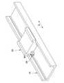
以下は各図面を参照しながら本発明について詳しく説明する。図1と図2に示されているように、本発明の潤滑チューブを備えたリニアレール装置は、リニアレール10と、スライディングブロック20と、2本の本発明の潤滑チューブ30と、2対の案内ユニット40と、2セットのビーズ50と、複数のネジ60とを有している。The present invention will be described in detail below with reference to the drawings. As shown in FIGS. 1 and 2, the linear rail device provided with the lubrication tube of the present invention comprises a
リニアレール10は所定の軸線方向Xに沿って延伸し、且つ互いに向かい合う1対の側壁11と、1対の側壁11を繋ぐ底壁12と、を有すると共に、1対の側壁11それぞれの互いに向かい合う面に軸線方向Xに沿って延伸する第1の案内溝13が凹設されている。The
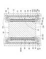
図2及び図3に示されているように、スライディングブロック20は軸線方向Xに沿って移動可能にリニアレール10の1対の側壁11の間に取り付けられていると共に、軸線方向X上の一側にある第1の端面21aと、第1の端面21aの反対側にある第2の端面21bと、第1の端面21aから第2の端面21bまで延伸するビーズ収容孔22と、第1の端面21a及び第2の端面21bにそれぞれに形成されていると共に、ビーズ収容孔22の近くに配置されている第1のネジ孔23と、ビーズ収容孔22に連通する潤滑油通路24と、各側壁11に形成された第1の案内溝13と向かい合って開口し、且つ、軸線方向Xに沿って延伸するビーズ通路を第1の案内溝13と共に画成するように形成された第2の案内溝25とを有するように形成されている。As shown in FIGS. 2 and 3, the
各ビーズ収容孔22は、それぞれに第1の端面21aまたは第2の端面21bに接し、且つ、内径が比較的に広い2つの大径部223と、2つの大径部223の間に介在し、且つ、内径が大径部223より狭い小径部222と、を有するように形成されている。Each
図4に示されているように、潤滑チューブ30は、多孔質材料により所定の中心軸線Lと平行に延伸する管内空間31を囲むように、管状に成形されていると共に、管内空間31に臨む内周面32と、内周面32の反対側にある外周面33とを有している。また、図5及び図6に示されているように、内周面32には、中心軸線Lと平行に延伸し、且つ、中心軸線Lに向かって開口するように形成された複数の第1の凹部321と、隣り合う2つの第1の凹部321の間に画成されて相対的に突起し、且つ、中心軸線Lと平行に延伸する複数の第1の突起部322と、が形成されている。更に、外周面33には、内周面32に形成される第1の凹部321の位置及び形状に対応して突起する第2の突起部331と、内周面32に形成される第1の突起部322の位置及び形状に対応して凹陥する第2の凹部332と、が形成されている。As shown in FIG. 4, the
更に、外周面33に形成された1つの第2の突起部331から、1つの第2の突起部331が対応する第1の凹部321まで貫通する潤滑油通過孔36が形成されている。Further, a lubricating
図5及び図6に示されているように、各潤滑チューブ30は、各ビーズ収容孔22内にそれぞれに挿入され、ビーズ収容孔22内に挿入されると、各潤滑チューブ30のそれぞれの中心軸線Lがリニアレール10の軸線方向Xと平行になり、更に、各潤滑チューブ30の中心軸線Lに沿った長さが対応するビーズ収容孔22の小径部222より長くなっているため、対応するビーズ収容孔22内に挿入される際、潤滑チューブ30の中心軸線L上にある両端部は対応するビーズ収容孔22の小径部222から2つの大径部223へ突出するようにビーズ収容孔22内に設置される。更に、各潤滑チューブ30が対応するビーズ収容孔22内に挿入される際、潤滑チューブ30に形成されている潤滑油通過孔36は、スライディングブロック20に形成されてビーズ収容孔22に連通する潤滑油通路24に向かって開口するように配置される。As shown in FIGS. 5 and 6, each
ちなみに、潤滑チューブ30に使用される多孔質材料としては、例えば高密度ポリエチレン粉末材料により熱圧成形されて形成されたものを使用することができる。Incidentally, as the porous material used for the
図4に示されているように、各案内ユニット40は、いずれもスライディングブロック20の第1の端面21a及び第2の端面21b外にそれぞれに露出するように取り付けられている本体部41と、本体部41から突起して対応のビーズ収容孔22内に挿し込まれるプラグ42と、を有している上、リニアレール10の側壁11に形成される第1の案内溝13とスライディングブロック20に形成される第2の案内溝25とにより画成されるビーズ通路に向かって開口する第1の開口431と、ビーズ収容孔22内に挿し込まれる潤滑チューブ30の管内空間31に向かって開口する第2の開口432と、第1の開口431から第2の開口432まで連通するビーズ通過路43と、を有するように形成されている。As shown in FIG. 4, each
本体部41には、スライディングブロック20に形成される第1のネジ孔23に対応する第2のネジ孔44が形成されており、各ネジ60は、案内ユニット40の本体部41に形成される第2のネジ孔44を経由してスライディングブロック20に形成される第1のネジ孔23にねじ込まれることにより、案内ユニット40をスライディングブロック20に固定することができる。A
プラグ42は、本体部41から突起して対応のビーズ収容孔22内の大径部223に挿し込まれてビーズ収容孔22内にある潤滑チューブ30に当接する第1の挿入部421と、第1の挿入部421の先端から延伸して潤滑チューブ30の外周面33とスライディングブロック20のビーズ収容孔22の大径部223に臨む壁面との間にある空間内に挿し込まれる第2の挿入部422と、を有する。なお、潤滑チューブ30の管内空間31に向かって開口する第2の開口432は、第1の挿入部421の潤滑チューブ30に当接する当接端面423に形成されている。The
また、潤滑チューブ30と案内ユニット40との係合のため、案内ユニット40の当接端面423には、潤滑チューブ30側へ突起する係合突起424が形成され、潤滑チューブ30の案内ユニット40の第1の挿入部421に当接する両端面34には、それぞれに係合突起423に対応して受け入れられる係合スロット35が形成されている。Further, due to the engagement between the
図5及び図7に示されているように、この構成により、リニアレール10の側壁11に形成される第1の案内溝13とスライディングブロック20に形成される第2の案内溝25とにより画成されるビーズ通路は、各案内ユニット40に形成されるビーズ通過路43を経由してビーズ収容孔22内に挿し込まれる潤滑チューブ30の管内空間31と繋がるようになって1つのサーキットを形成し、1セットのビーズ50はこのサーキット内に設置されてベアリングとしての役割を果たすことができる。更に、ビーズ収容孔22内に挿し込まれる潤滑チューブ30の位置は、その両端側にそれぞれに取り付けられている1対の案内ユニット40によって動かないように固定されるようになる。As shown in FIGS. 5 and 7, with this configuration, the
このように、2本の潤滑チューブ30が2つのビーズ収容孔22内にそれぞれ挿し込まれた状態で、各ビーズ収容孔22に対してそれぞれに1対の案内ユニット40を取り付けて潤滑チューブ30を固定することにより、潤滑チューブ30に形成される潤滑油通過孔36を、スライディングブロック20に形成された潤滑油通路24の開口に確実にあわせることができる。また、案内ユニット40はネジ60によりスライディングブロック20に固定され、リニアレール10の側壁11に形成される第1の案内溝13とスライディングブロック20に形成される第2の案内溝25とにより画成されるビーズ通路からのビーズ50をビーズ通過路43で潤滑チューブ30の管内空間31へ案内することができる。In this way, with the two
潤滑油通路24を経由して潤滑油をビーズ収容孔22内に注入すると、潤滑油はビーズ収容孔22の内周壁と潤滑チューブ30の外周面33に形成される第2の凹部332との間の空間を充満すると共に、潤滑チューブ30に形成される潤滑油通過孔36及び潤滑チューブ30の多孔質材料により、潤滑チューブ30の内周面32に形成される第1の凹部321と潤滑チューブ30の管内空間31内にあるビーズ50との間の空間を充満するようになり、これによりスライディングブロック20がリニアレール10に沿って移動する際、ビーズ50は確実にベアリングとしての役割を果たすことができると共に、リニアレール装置の使用寿命も延び、潤滑油を頻繁に補充する必要もなくなる。When the lubricating oil is injected into the
また、本発明のリニアレール装置では、ビーズ収容孔22の内周壁とビーズ50の間に潤滑チューブ30が介在するため、ビーズ50のサイズに合わせてビーズ収容孔22を形成する必要がなく、ビーズ収容孔22を広めに形成することができるため、製造のコストを節約することができる。Further, in the linear rail device of the present invention, since the
更に、潤滑チューブ30に使用される多孔質材料としては、例えば高密度ポリエチレン粉末材料により熱圧成形されて形成されたものを使用するので、潤滑チューブ30自体が大量の潤滑油を吸収することができ、潤滑チューブ30を通過するビーズ50に潤滑油を供給し続けることができる。Further, as the porous material used for the lubricating
そして、潤滑チューブ30に形成される潤滑油通過孔36は、外周面33に形成された第2の突起部331から、1つの第2の突起部331が対応する第1の凹部321まで貫通するように形成されるので、潤滑油通過孔36を形成する際にばりが生じても、それが内周面33の第1の凹部321にあるため、ビーズ50の作動に干渉することはない。The lubricating
ビーズ50として直径4.7mmのものを使用し、そして潤滑チューブの厚さが1mmの場合、従来では潤滑油を貯蔵可能な空間の断面積は5.609mm2であるが、本発明の潤滑チューブ30は外周面33に第2の突起部331と第2の凹部332が形成され、内周面32に第1の凹部321と第1の突起部322が形成されるため、潤滑油を貯蔵可能な空間の断面積は10.128mm2となり、即ち従来の約1.8倍の潤滑油を貯蔵することができる。また、潤滑チューブ30とビーズ50の間に隙間が存在するため、潤滑油による潤滑効果を最適化することができる。When a
本発明において案内ユニット40のプラグ42に係合突起423が形成され、そして潤滑チューブ30側にも係合突起423に対応して受け入れられる係合スロット35が形成されているので、この構成により潤滑チューブ30は回転不能にビーズ収容孔22内に保持されるようになり、潤滑油通過孔36を確実にスライディングブロック20に形成された潤滑油通路24の開口にあわせることができる。更に、1対の案内ユニット40がそれぞれに有するプラグ42でビーズ収容孔22内に挿し込んで潤滑チューブ30を挟むので、潤滑チューブ30とビーズ収容孔22との加工誤差、および案内ユニット40が取り付けられる際の誤差を吸収し、案内ユニット40の第2の開口432と潤滑チューブ30の管内空間との間に段差が生じないようにすることができる。In the present invention, the
上記構成により、本発明の潤滑チューブは多孔質材料により管状に成形された上、その管内空間に臨む内周面には、複数の第1の突起部と、隣り合う2つの前記第1の突起部の間に画成されて相対的に凹陥する複数の第1の凹部と、が形成されているので、複数の第1の凹部に多量な潤滑油を貯蔵することが可能であり、潤滑油を補充する頻度を抑えることにより、メンテナンスのコストを抑えることができる。With the above configuration, the lubricating tube of the present invention is formed into a tubular shape made of a porous material, and on the inner peripheral surface facing the space inside the tube, a plurality of first protrusions and two adjacent first protrusions are formed. Since a plurality of first recesses defined between the portions and relatively recessed are formed, it is possible to store a large amount of lubricating oil in the plurality of first recesses, and the lubricating oil can be stored. By reducing the frequency of replenishment, maintenance costs can be reduced.
10 リニアレール
11 側壁
12 底壁
13 第1の案内溝
20 スライディングブロック
21a 第1の端面
21b 第2の端面
22 ビーズ収容孔
222 小径部
223 大径部
23 第1のネジ孔
24 潤滑油通路
25 第2の案内溝
30 潤滑チューブ
31 管内空間
32 内周面
321 第1の凹部
322 第1の突起部
33 外周面
331 第2の突起部
332 第2の凹部
34 端面
35 係合スロット
36 潤滑油通過孔
40 案内ユニット
41 本体部
42 プラグ
421 第1の挿入部
422 第2の挿入部
423 当接端面
424 係合突起
43 ビーズ通過路
431 第1の開口
431 第2の開口
44 第2のネジ孔
50 ビーズ
60 ネジ10
Claims (4)
Translated fromJapanese前記内周面には、前記中心軸線と平行に延伸し、且つ、前記中心軸線に向かって開口するように形成された複数の第1の凹部と、隣り合う2つの前記第1の凹部の間に画成されて相対的に突起し、且つ、前記中心軸線と平行するように延伸する複数の第1の突起部と、が形成されており、
前記外周面には、前記第1の突起部の位置及び形状に対応して凹陥する第2の凹部と、前記第1の凹部の位置及び形状に対応して突起する第2の突起部と、が形成されており、
前記外周面に形成された1つの前記第2の突起部から、当該1つの前記第2の突起部が対応する前記第1の凹部まで貫通する潤滑油通過孔が更に形成されている
ことを特徴とする潤滑チューブ。A lubrication tube formed into a tubular shape so as to surround an inner space extending along a predetermined central axis by a porous material, and is an inner peripheral surface facing the inner space of the pipe and an outer circumference on the opposite side of the inner peripheral surface. Has a surface and
On the inner peripheral surface, between a plurality of first recesses extending parallel to the central axis and opening toward the central axis, and two adjacent first recesses. A plurality of first protrusions, which are defined in the above and are relatively protruding and extend so as to be parallel to the central axis, are formed.
On the outer peripheral surface, a second recess corresponding to the position and shape of the first protrusion, a second protrusion corresponding to the position and shape of the first recess, and a second protrusion. Is formed,
A lubricating oil passage hole is further formed from the one second protrusion formed on the outer peripheral surface to the first recess corresponding to the one second protrusion.
Lubricating tube characterized by that.
前記軸線方向に沿って移動可能に前記リニアレールに取り付けられていると共に、前記軸線方向上の一側にある第1の端面と、該第1の端面の反対側にある第2の端面と、前記第1の端面から前記第2の端面まで延伸するビーズ収容孔と、前記ビーズ収容孔に連通する潤滑油通路と、前記側壁に形成された前記第1の案内溝と向かい合って開口し、前記軸線方向に沿って延伸するビーズ通路を共に画成するように形成された第2の案内溝とを有するように形成されたスライディングブロックと、
前記ビーズ収容孔内に挿し込まれる中空管状の潤滑チューブと、
前記ビーズ収容孔の前記第1の端面及び前記第2の端面における開口にそれぞれに取り付けられる一対の案内ユニットと、を有するリニアレール装置であって、
前記潤滑チューブは、多孔質材料により所定の中心軸線と平行に延伸する管内空間を囲むように管状に成形されていると共に、前記管内空間に臨む内周面と、当該内周面の反対側にある外周面とを有しており、前記内周面には、前記中心軸線と平行に延伸し、且つ、前記中心軸線に向かって開口するように形成された複数の第1の凹部と、隣り合う2つの前記第1の凹部の間に画成されて相対的に突起し、且つ、前記中心軸線と平行に延伸する複数の第1の突起部と、が形成されており、
前記一対の案内ユニットは、いずれも前記ビーズ通路に向かって開口する第1の開口と、前記ビーズ収容孔内に挿し込まれる前記潤滑チューブの管内空間に向かって開口する第2の開口と、前記第1の開口から前記第2の開口まで連通するビーズ通過路と、を有するように形成されており、
前記潤滑チューブの前記外周面には、前記第1の突起部の位置及び形状に対応して凹陥する第2の凹部と、前記第1の凹部の位置及び形状に対応して突起する第2の突起部と、が形成されており、
前記潤滑チューブの前記外周面に形成された1つの前記第2の突起部から、当該1つの前記第2の突起部が対応する前記第1の凹部まで貫通する潤滑油通過孔が更に形成されている
ことを特徴とするリニアレール装置。A linear rail having a side wall extending along a predetermined axial direction and having a first guide groove extending along the axial direction recessed in the side wall.
A first end face on one side in the axial direction and a second end face on the opposite side of the first end face, which are movably attached to the linear rail along the axis direction. The bead accommodating hole extending from the first end face to the second end surface, the lubricating oil passage communicating with the bead accommodating hole, and the first guide groove formed in the side wall are opened facing each other. A sliding block formed to have a second guide groove formed to together define a bead passage extending along the axial direction, and a sliding block.
A hollow tubular lubricating tube inserted into the bead storage hole,
A linear rail device comprising a pair of guide units attached to each of the first end face and the opening in the second end face of the bead accommodating hole.
The lubrication tube is formed into a tubular shape by a porous material so as to surround an inner space extending in parallel with a predetermined central axis, and is on the inner peripheral surface facing the inner space of the pipe and on the opposite side of the inner peripheral surface. It has a certain outer peripheral surface, and the inner peripheral surface is adjacent to a plurality of first recesses formed so as to extend in parallel with the central axis and open toward the central axis. A plurality of first protrusions that are defined and relatively project between the two matching first recesses and that extend parallel to the central axis are formed.
The pair of guide units each have a first opening that opens toward the bead passage, a second opening that opens toward the in-pipe space of the lubrication tube inserted into the bead accommodating hole, and the above-mentioned. It is formed to have a bead passage that communicates from the first opening to the second opening.
On the outer peripheral surface of the lubricating tube, a second recess corresponding to the position and shape of the first protrusion and a second recess corresponding to the position and shape of the first recess are projected. A protrusion is formed,
A lubricating oil passage hole is further formed from the one second protrusion formed on the outer peripheral surface of the lubrication tube to the corresponding first recess to which the one second protrusion corresponds. Are
A linear rail device characterized by that.
前記スライディングブロック外に露出するように取り付けられている本体部と、
前記本体部から突起して前記ビーズ収容孔内に挿し込まれるプラグと、を有しており、
前記プラグは、前記本体部から突起して前記ビーズ収容孔内に挿し込まれて前記ビーズ収容孔内にある前記潤滑チューブに当接する第1の挿入部と、前記第1の挿入部の先端から延伸して前記潤滑チューブの外周面と前記スライディングブロックの前記ビーズ収容孔に臨む壁面との間にある空間内に挿し込まれる第2の挿入部と、を有し、
前記第1の挿入部の前記潤滑チューブに当接する当接端面に、前記潤滑チューブの管内空間に向かって開口する前記第2の開口が形成されていることを特徴とする請求項2に記載のリニアレール装置。Each of the pair of guide units includes a main body portion that is attached so as to be exposed to the outside of the sliding block.
It has a plug that protrudes from the main body and is inserted into the bead accommodating hole.
The plug protrudes from the main body and is inserted into the bead accommodating hole from a first insertion portion that abuts on the lubricating tube in the bead accommodating hole and from the tip of the first insertion portion. It has a second insertion portion that is stretched and inserted into the space between the outer peripheral surface of the lubricating tube and the wall surface of the sliding block facing the bead accommodating hole.
The second aspect of claim2 , wherein the second opening that opens toward the in-pipe space of the lubrication tube is formed on the contact end surface of the first insertion portion that abuts on the lubrication tube. Linear rail device.
前記潤滑チューブの前記案内ユニットの前記第1の挿入部に当接する両端面に、それぞれに前記係合突起に対応して受け入れられる係合スロットが形成されていることを特徴とする請求項3に記載のリニアレール装置。In each of the pair of guide units, an engaging protrusion protruding toward the lubricating tube side is formed on the contact end surface.
3. Thethird aspect of the present invention is characterized in that engagement slots corresponding to the engagement protrusions are formed on both end faces of the lubrication tube in contact with the first insertion portion of the guide unit. The linear rail device described.
Applications Claiming Priority (2)
| Application Number | Priority Date | Filing Date | Title |
|---|---|---|---|
| TW108135547 | 2019-10-01 | ||
| TW108135547ATWI691655B (en) | 2019-10-01 | 2019-10-01 | Lubrication duct and sliding table device with lubrication duct |
Publications (2)
| Publication Number | Publication Date |
|---|---|
| JP2021055827A JP2021055827A (en) | 2021-04-08 |
| JP6993008B2true JP6993008B2 (en) | 2022-01-13 |
Family
ID=71134419
Family Applications (1)
| Application Number | Title | Priority Date | Filing Date |
|---|---|---|---|
| JP2020019433AActiveJP6993008B2 (en) | 2019-10-01 | 2020-02-07 | Linear rail device with lubrication tube and lubrication tube |
Country Status (5)
| Country | Link |
|---|---|
| US (1) | US11067125B2 (en) |
| JP (1) | JP6993008B2 (en) |
| KR (1) | KR102346452B1 (en) |
| CN (1) | CN112594283B (en) |
| TW (1) | TWI691655B (en) |
Families Citing this family (7)
| Publication number | Priority date | Publication date | Assignee | Title |
|---|---|---|---|---|
| KR20220060244A (en)* | 2020-11-04 | 2022-05-11 | 현대자동차주식회사 | Seat rail for vehicle |
| TWI769806B (en)* | 2021-05-03 | 2022-07-01 | 東佑達自動化科技股份有限公司 | Compound screw slide table |
| CN116181797A (en)* | 2021-11-29 | 2023-05-30 | 银泰科技股份有限公司 | Linear slide rail and guide rail lubricating structure thereof |
| CN116181796A (en)* | 2021-11-29 | 2023-05-30 | 银泰科技股份有限公司 | Linear slide rail and chain belt lubricating structure thereof |
| TWI812405B (en)* | 2022-08-16 | 2023-08-11 | 東佑達自動化科技股份有限公司 | slide device |
| WO2024154341A1 (en)* | 2023-01-20 | 2024-07-25 | 黒田精工株式会社 | Ball screw actuator |
| WO2024154340A1 (en)* | 2023-01-20 | 2024-07-25 | 黒田精工株式会社 | Ball screw actuator |
Citations (2)
| Publication number | Priority date | Publication date | Assignee | Title |
|---|---|---|---|---|
| JP2001082469A (en) | 1999-09-10 | 2001-03-27 | Nippon Thompson Co Ltd | Linear motion rolling guide unit |
| JP3173993U (en) | 2011-12-19 | 2012-03-01 | 日本特殊ベアリング株式会社 | Ball spline with lubrication mechanism |
Family Cites Families (23)
| Publication number | Priority date | Publication date | Assignee | Title |
|---|---|---|---|---|
| JPH0527407U (en)* | 1991-09-25 | 1993-04-09 | 日本精工株式会社 | Ball screw integrated linear motion guide unit |
| JPH10205534A (en)* | 1997-01-17 | 1998-08-04 | Nippon Thompson Co Ltd | Linear motion guide unit with lubrication plate |
| DE19851995B4 (en)* | 1997-11-11 | 2006-01-12 | Nsk Ltd. | Continuously adjustable toroidal transmission |
| US6712511B2 (en)* | 2001-02-21 | 2004-03-30 | Nippon Thompson Co., Ltd. | Linear motion guide unit |
| DE60108063T2 (en)* | 2001-02-23 | 2005-12-15 | Nippon Thompson Co. Ltd. | Linear guide unit |
| DE102004018820A1 (en)* | 2004-04-19 | 2005-11-03 | Rexroth Star Gmbh | Linear guide device and method for its production |
| DE602005007678D1 (en)* | 2004-11-11 | 2008-08-07 | Nsk Ltd | Linear roller bearing and Wälzkörperkette for it |
| JP2006220276A (en)* | 2005-02-14 | 2006-08-24 | Nsk Ltd | Separator for linear motion guide device and linear motion guide device |
| DE102006012623A1 (en)* | 2006-03-20 | 2007-09-27 | Schaeffler Kg | A roller chain |
| JP5570217B2 (en)* | 2007-09-27 | 2014-08-13 | Thk株式会社 | Linear guide device |
| DE102009009011B4 (en)* | 2009-02-16 | 2023-02-02 | Robert Bosch Gmbh | Linear motion device with partially supported rolling surface part |
| WO2010137755A1 (en)* | 2009-05-28 | 2010-12-02 | (주)팜코 | Adjustable preload type linear guide system |
| TWM379483U (en)* | 2009-12-25 | 2010-05-01 | Hiwin Mikrosystem Corp | Platform with automatic lubrication mechanism |
| TWM387174U (en)* | 2010-04-02 | 2010-08-21 | Goldtech Motion Technology Co Ltd | Linear motion module |
| TWM404292U (en)* | 2010-12-22 | 2011-05-21 | Tbi Motion Technology Co Ltd | Linear motion module with self-lubricating function |
| CN201902448U (en)* | 2010-12-28 | 2011-07-20 | 全球传动科技股份有限公司 | Linear motion module with self-lubricating function |
| US9337703B2 (en)* | 2011-06-08 | 2016-05-10 | Johnson Electric S.A. | Thrust bearing assembly |
| TWI503489B (en)* | 2012-05-23 | 2015-10-11 | Chieftech Prec Co Ltd | Circulation maintaining device and its half mediate plates for linear slide assembly |
| CN202867560U (en)* | 2012-09-28 | 2013-04-10 | 全球传动科技股份有限公司 | Ball spline set and its outer cylinder |
| US9163665B2 (en)* | 2013-09-27 | 2015-10-20 | Ome Technology Co., Ltd. | Linear guideway |
| CN106415070A (en)* | 2013-11-25 | 2017-02-15 | 斯凯孚公司 | Linear Electromechanical Actuator |
| JP6716231B2 (en)* | 2015-11-11 | 2020-07-01 | 日本トムソン株式会社 | Bending rolling guide unit |
| CN206785869U (en)* | 2017-06-14 | 2017-12-22 | 丽水市远锦传动科技有限公司 | A kind of straight-line guide rail slide block |
- 2019
- 2019-10-01TWTW108135547Apatent/TWI691655B/enactive
- 2020
- 2020-01-03CNCN202010003772.6Apatent/CN112594283B/enactiveActive
- 2020-01-22USUS16/749,379patent/US11067125B2/enactiveActive
- 2020-02-07JPJP2020019433Apatent/JP6993008B2/enactiveActive
- 2020-03-13KRKR1020200031191Apatent/KR102346452B1/enactiveActive
Patent Citations (2)
| Publication number | Priority date | Publication date | Assignee | Title |
|---|---|---|---|---|
| JP2001082469A (en) | 1999-09-10 | 2001-03-27 | Nippon Thompson Co Ltd | Linear motion rolling guide unit |
| JP3173993U (en) | 2011-12-19 | 2012-03-01 | 日本特殊ベアリング株式会社 | Ball spline with lubrication mechanism |
Also Published As
| Publication number | Publication date |
|---|---|
| CN112594283A (en) | 2021-04-02 |
| JP2021055827A (en) | 2021-04-08 |
| TW202115325A (en) | 2021-04-16 |
| US11067125B2 (en) | 2021-07-20 |
| US20210095718A1 (en) | 2021-04-01 |
| TWI691655B (en) | 2020-04-21 |
| KR20210039912A (en) | 2021-04-12 |
| CN112594283B (en) | 2022-04-29 |
| KR102346452B1 (en) | 2021-12-31 |
Similar Documents
| Publication | Publication Date | Title |
|---|---|---|
| JP6993008B2 (en) | Linear rail device with lubrication tube and lubrication tube | |
| JP4584888B2 (en) | Linear motion guidance unit | |
| JP4685723B2 (en) | Linear motion guidance unit | |
| JP2002147561A (en) | Ball screw device with lubrication device | |
| JP2010014228A (en) | Lubricating member for linear motion rolling guide unit, and slider for linear motion rolling guide unit | |
| JP2015224713A (en) | Linear rolling guide unit | |
| JP5550918B2 (en) | Linear motion guidance unit | |
| WO2015068653A1 (en) | Roller bearing guide device | |
| JP2005069343A (en) | Guidance unit | |
| JP5052270B2 (en) | Slider for linear motion rolling guide unit | |
| JP6393496B2 (en) | Linear motion guide unit with lubrication member | |
| JP2006144840A (en) | Linear motion guidance unit | |
| CN113958561A (en) | Restrictor for air-floating part and air-floating piston comprising restrictor | |
| CN115306824B (en) | Linear guide | |
| JP5938196B2 (en) | Linear motion rolling guide unit | |
| JP6417714B2 (en) | Rolling bearing guide device | |
| JP4881481B1 (en) | Lubricant supply structure for ball screw integrated linear motion guide bearing | |
| JP6439333B2 (en) | Rolling bearing guide device | |
| KR102453000B1 (en) | Roller type slide rail with oil storage function and its oil storage accessories | |
| JP4488715B2 (en) | Rolling guide unit | |
| JP2006316828A (en) | Chain with oil reservoir | |
| TW202441088A (en) | Linear Guides | |
| JP2023152446A (en) | Linear motion guide device | |
| JP2025012016A (en) | Linear guide | |
| JP2024146228A (en) | Linear guide |
Legal Events
| Date | Code | Title | Description |
|---|---|---|---|
| A621 | Written request for application examination | Free format text:JAPANESE INTERMEDIATE CODE: A621 Effective date:20200207 | |
| A131 | Notification of reasons for refusal | Free format text:JAPANESE INTERMEDIATE CODE: A131 Effective date:20210406 | |
| A521 | Request for written amendment filed | Free format text:JAPANESE INTERMEDIATE CODE: A523 Effective date:20210622 | |
| A871 | Explanation of circumstances concerning accelerated examination | Free format text:JAPANESE INTERMEDIATE CODE: A871 Effective date:20210914 | |
| TRDD | Decision of grant or rejection written | ||
| A01 | Written decision to grant a patent or to grant a registration (utility model) | Free format text:JAPANESE INTERMEDIATE CODE: A01 Effective date:20211109 | |
| A61 | First payment of annual fees (during grant procedure) | Free format text:JAPANESE INTERMEDIATE CODE: A61 Effective date:20211202 | |
| R150 | Certificate of patent or registration of utility model | Ref document number:6993008 Country of ref document:JP Free format text:JAPANESE INTERMEDIATE CODE: R150 | |
| R250 | Receipt of annual fees | Free format text:JAPANESE INTERMEDIATE CODE: R250 | |
| R250 | Receipt of annual fees | Free format text:JAPANESE INTERMEDIATE CODE: R250 |