JP6988060B2 - Image processing equipment, image processing system, image processing method and program - Google Patents
Image processing equipment, image processing system, image processing method and programDownload PDFInfo
- Publication number
- JP6988060B2 JP6988060B2JP2016104554AJP2016104554AJP6988060B2JP 6988060 B2JP6988060 B2JP 6988060B2JP 2016104554 AJP2016104554 AJP 2016104554AJP 2016104554 AJP2016104554 AJP 2016104554AJP 6988060 B2JP6988060 B2JP 6988060B2
- Authority
- JP
- Japan
- Prior art keywords
- screen
- image processing
- image
- display
- notebook
- Prior art date
- Legal status (The legal status is an assumption and is not a legal conclusion. Google has not performed a legal analysis and makes no representation as to the accuracy of the status listed.)
- Active
Links
Images


Classifications
- G—PHYSICS
- G06—COMPUTING OR CALCULATING; COUNTING
- G06F—ELECTRIC DIGITAL DATA PROCESSING
- G06F3/00—Input arrangements for transferring data to be processed into a form capable of being handled by the computer; Output arrangements for transferring data from processing unit to output unit, e.g. interface arrangements
- G06F3/01—Input arrangements or combined input and output arrangements for interaction between user and computer
- G06F3/048—Interaction techniques based on graphical user interfaces [GUI]
- G06F3/0487—Interaction techniques based on graphical user interfaces [GUI] using specific features provided by the input device, e.g. functions controlled by the rotation of a mouse with dual sensing arrangements, or of the nature of the input device, e.g. tap gestures based on pressure sensed by a digitiser
- G06F3/0488—Interaction techniques based on graphical user interfaces [GUI] using specific features provided by the input device, e.g. functions controlled by the rotation of a mouse with dual sensing arrangements, or of the nature of the input device, e.g. tap gestures based on pressure sensed by a digitiser using a touch-screen or digitiser, e.g. input of commands through traced gestures
- G06F3/04883—Interaction techniques based on graphical user interfaces [GUI] using specific features provided by the input device, e.g. functions controlled by the rotation of a mouse with dual sensing arrangements, or of the nature of the input device, e.g. tap gestures based on pressure sensed by a digitiser using a touch-screen or digitiser, e.g. input of commands through traced gestures for inputting data by handwriting, e.g. gesture or text
- G—PHYSICS
- G06—COMPUTING OR CALCULATING; COUNTING
- G06F—ELECTRIC DIGITAL DATA PROCESSING
- G06F3/00—Input arrangements for transferring data to be processed into a form capable of being handled by the computer; Output arrangements for transferring data from processing unit to output unit, e.g. interface arrangements
- G06F3/14—Digital output to display device ; Cooperation and interconnection of the display device with other functional units
- G06F3/1423—Digital output to display device ; Cooperation and interconnection of the display device with other functional units controlling a plurality of local displays, e.g. CRT and flat panel display
- G—PHYSICS
- G06—COMPUTING OR CALCULATING; COUNTING
- G06F—ELECTRIC DIGITAL DATA PROCESSING
- G06F3/00—Input arrangements for transferring data to be processed into a form capable of being handled by the computer; Output arrangements for transferring data from processing unit to output unit, e.g. interface arrangements
- G06F3/14—Digital output to display device ; Cooperation and interconnection of the display device with other functional units
- G06F3/1454—Digital output to display device ; Cooperation and interconnection of the display device with other functional units involving copying of the display data of a local workstation or window to a remote workstation or window so that an actual copy of the data is displayed simultaneously on two or more displays, e.g. teledisplay
- G—PHYSICS
- G06—COMPUTING OR CALCULATING; COUNTING
- G06F—ELECTRIC DIGITAL DATA PROCESSING
- G06F2203/00—Indexing scheme relating to G06F3/00 - G06F3/048
- G06F2203/048—Indexing scheme relating to G06F3/048
- G06F2203/04803—Split screen, i.e. subdividing the display area or the window area into separate subareas
- G—PHYSICS
- G09—EDUCATION; CRYPTOGRAPHY; DISPLAY; ADVERTISING; SEALS
- G09G—ARRANGEMENTS OR CIRCUITS FOR CONTROL OF INDICATING DEVICES USING STATIC MEANS TO PRESENT VARIABLE INFORMATION
- G09G2340/00—Aspects of display data processing
- G09G2340/04—Changes in size, position or resolution of an image
- G09G2340/0407—Resolution change, inclusive of the use of different resolutions for different screen areas
- G—PHYSICS
- G09—EDUCATION; CRYPTOGRAPHY; DISPLAY; ADVERTISING; SEALS
- G09G—ARRANGEMENTS OR CIRCUITS FOR CONTROL OF INDICATING DEVICES USING STATIC MEANS TO PRESENT VARIABLE INFORMATION
- G09G2340/00—Aspects of display data processing
- G09G2340/12—Overlay of images, i.e. displayed pixel being the result of switching between the corresponding input pixels
Landscapes
- Engineering & Computer Science (AREA)
- Theoretical Computer Science (AREA)
- General Engineering & Computer Science (AREA)
- Human Computer Interaction (AREA)
- Physics & Mathematics (AREA)
- General Physics & Mathematics (AREA)
- Controls And Circuits For Display Device (AREA)
- User Interface Of Digital Computer (AREA)
- Two-Way Televisions, Distribution Of Moving Picture Or The Like (AREA)
Description
Translated fromJapanese本発明は、画像処理装置、画像処理システム、画像処理方法及びプログラムに関する。 The present invention relates to an image processing apparatus, an image processing system, an image processing method and a program.
従来、企業、教育機関又は行政機関等における会議等において、大型ディスプレイに背景画像を表示させ、この背景画像の上に、ユーザが文字、数字又は図形等のストローク画像を描画することができる電子黒板が利用されている。 Conventionally, at a conference in a company, educational institution, government agency, etc., a background image is displayed on a large display, and a user can draw a stroke image such as characters, numbers, or figures on the background image. Is being used.
このような電子黒板に係るシステムの一例として、例えば、システム全体の小型化及び一体化を図ると共に、操作性、取扱性及び利便性の向上を図る方法が知られている。具体的には、まず、文字及び画像を表示する表示装置、表示装置の前面にタッチパネル面を配設したタッチ入力装置、印刷装置、タッチ入力装置からの入力に基づいて表示装置による表示並びに印刷装置による印刷を制御する制御装置を電子黒板システムが備える。この電子黒板システムでは、デジタルカメラ、DVDプレイヤ又はビデオ機器等の情報処理装置を接続する複数の接続端子を用いるため、表示装置が、大画面モニタとして使用できる。ゆえに、この電子黒板システムでは、ユーザは、パーソナルコンピュータを介さず、情報処理装置を接続させたり、情報処理装置に対して操作を行うことができ、操作性、取扱性及び利便性の向上を図ることができる方法が知られている(例えば、特許文献1等)。 As an example of such a system related to an electronic blackboard, for example, a method for reducing the size and integration of the entire system and improving operability, handleability, and convenience is known. Specifically, first, a display device for displaying characters and images, a touch input device having a touch panel surface arranged on the front surface of the display device, a printing device, a display by a display device based on input from the touch input device, and a printing device. The electronic blackboard system is equipped with a control device for controlling printing by the electronic touch panel system. Since this electronic blackboard system uses a plurality of connection terminals for connecting information processing devices such as a digital camera, a DVD player, or a video device, the display device can be used as a large screen monitor. Therefore, in this electronic blackboard system, the user can connect an information processing device or operate the information processing device without going through a personal computer, and improve operability, handleability, and convenience. There are known methods that can be used (for example,
しかしながら、電子黒板等である画像表示装置に接続され、かつ、ディスプレイ等の出力装置を有する画像処理装置は、画像表示装置と、画像処理装置が有する出力装置とに、それぞれ異なる画面を表示させる場合等がある。すなわち、複数の画面が存在する場合がある。このような場合において、例えば、画面を示す画像データを生成する、いわゆるキャプチャ等を行う場合、複数の画面がどこで区切れるのかが不明となり、ユーザが望む画像データが生成されないことが問題である。 However, in an image processing device connected to an image display device such as an electronic blackboard and having an output device such as a display, when the image display device and the output device of the image processing device display different screens. And so on. That is, there may be a plurality of screens. In such a case, for example, when generating image data showing a screen, so-called capture, etc., it is unclear where a plurality of screens are separated, and the problem is that the image data desired by the user is not generated.
本発明は、上記課題に鑑み、画面の区切りを判別できる画像処理装置を提供することを目的とする。In view of the above problems, it is an object of the present invention to provide an image processing apparatuscapable of discriminating screen divisions.
上述した課題を解決するために、本発明の一態様における、表示装置に接続される画像処理装置は、
前記画像処理装置のディスプレイに表示される第1画面と、前記画像処理装置のディスプレイの拡張として前記表示装置のディスプレイに表示される第2画面とを表示させる表示部と、
前記第1画面と、前記第2画面とを識別するデータを少なくとも有する識別データを前記表示装置から取得する取得部と、
前記識別データに基づいて、前記第1画面及び前記第2画面の区切りを判別する判別部と、
前記第1画面に表示されるグラフィックユーザインタフェースの第1面積と、前記第2画面に表示される前記グラフィックユーザインタフェースの第2面積とを比較し前記第1画面又は前記第2画面のいずれかを取り込んで、画像データを生成する画像処理部と
を備えることを特徴とする。
In order to solve the above-mentioned problems, the image processing device connected to the display device in one aspect of the present invention is
A display unit for displaying a first screen displayed on the display of the image processing device and a second screen displayed on the display of the display device as an extension of the display of the image processing device.
An acquisition unit that acquires identification data from the display device that has at least data that identifies the first screen and the second screen.
Based on the identification data, a discriminating unit that discriminates between the first screen and the second screen, and a discriminating unit.
A first area of the graphical user interface displayed on the first screen,either the second on the screen compared with the second area ofthe graphic user interfacethe first screen or the second screen It is characterized by includingan image processing unit that captures and generates image data.
画面の区切りを判別できる画像処理装置を提供することができる。It is possible to provide an image processing devicecapable of determining a screen break.
以下、本発明を実施するための形態について図面を参照しながら説明する。 Hereinafter, embodiments for carrying out the present invention will be described with reference to the drawings.
<システム例の概要>
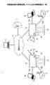
図1は、本実施形態の画像処理システム1の全体構成図の一例である。なお、図1では、説明を簡略化するために、画像表示装置の例である2台の電子黒板2a、2b及びこれに付随する電子ペン4a、4b等を示す。したがって、画像処理システム1では、3台以上の電子黒板又は電子ペン等が利用されてもよい。<Overview of system example>
FIG. 1 is an example of an overall configuration diagram of the
また、図示するように、画像処理システム1は、複数の電子黒板2a、2b、複数の電子ペン4a、4b、USBメモリ5a、5b、画像処理装置の例であるノートPC(Personal Computer)6a、6b、テレビ(ビデオ)会議端末7a、7b、アカウントサーバ11及びPC8を有する。さらに、電子黒板2a、2b、及びPC8は、通信ネットワーク9を介して通信可能に接続される。さらにまた、複数の電子黒板2a、2bには、それぞれディスプレイ3a、3bが設けられる。 Further, as shown in the figure, the
また、電子黒板2aには、電子ペン4aによって生じたイベント(ディスプレイ3aに電子ペン4aのペン先、又は、電子ペン4aのペン尻のタッチ)による描画された画像を、ディスプレイ3aに表示させることができる。なお、電子ペン4aだけでなく、ユーザの手Ha等によって生じたイベント(拡大、縮小、ページめくり等のジェスチャ)に基づいて、ディスプレイ3a上に表示されている画像を変更させることもできる。イベントにより、電子ペン4a又は手Haなどが指示する位置情報が電子黒板2aに入力される。 Further, on the
また、電子黒板2aには、USBメモリ5aが接続可能であり、電子黒板2aはUSBメモリ5aからPDF(Portable Document Format)等の電子ファイルを読み出したり、電子黒板2aはUSBメモリ5aに電子ファイルを記録したりすることができる。また、電子黒板2aには、DisplayPort(登録商標)、DVI(Digital Visual Interface)、HDMI(登録商標)(High−Definition Multimedia Interface)及びVGA(Video Graphics Array)等の規格による通信が可能なケーブル10a1を介して、ノートPC6aが接続される。そして、電子黒板2aは、ディスプレイ3aに対する接触によってイベントを発生させ、このイベントを示すイベント情報を、マウスやキーボード等の入力装置からのイベントと同様に、ノートPC6aに送信することでノートPC6aを制御することができる。同じく、電子黒板2aには、上記規格による通信が可能なケーブル10a2を介して、テレビ(ビデオ)会議端末7aが接続されている。なお、ノートPC6a及びテレビ会議端末7aは、Bluetooth(登録商標)等の各種無線通信プロトコルに準拠した無線通信により、電子黒板2aと通信してもよい。 Further, a
一方、電子黒板2bが設置されている他の拠点では、上記と同様に、ディスプレイ3bを備えた電子黒板2b、電子ペン4b、USBメモリ5b、ノートPC6b、テレビ会議端末7b、ケーブル10b1、ケーブル10b2が利用される。更に、ユーザの手Hb等によって生じたイベントに基づいて、ディスプレイ3b上に表示されている画像を変更させることもできる。 On the other hand, at other bases where the electronic blackboard 2b is installed, similarly to the above, the electronic blackboard 2b equipped with the
これにより、一の拠点で電子黒板2aのディスプレイ3a上に描画された画像は、他の拠点で電子黒板2bのディスプレイ3b上にも表示され、逆に他の拠点で電子黒板2bのディスプレイ3b上に描画された画像は、一の拠点で電子黒板2aのディスプレイ3a上に表示される。このように、画像処理システム1では、遠隔地において同じ画像を共有する遠隔共有処理を行うことができるため、遠隔地での会議等に用いると、非常に便利である。 As a result, the image drawn on the
<用語について>
以下では、複数の電子黒板のうち任意の電子黒板を示す場合には「電子黒板2」と示す。複数の電子黒板2が有するディスプレイのうち任意のディスプレイを示す場合には「ディスプレイ3」と示す。複数の電子ペンのうち任意の電子ペンを示す場合には「電子ペン4」と示す。複数のUSBメモリのうち任意のUSBメモリを示す場合には「USBメモリ5」と示す。複数のノートPCのうち任意のノートPCを示す場合には「ノートPC6」と示す。複数のテレビ会議端末のうち任意のテレビ会議端末を示す場合には「テレビ会議端末7」と示す。また、複数のユーザの手のうち任意の手を示す場合には「手H」と示す。複数のケーブルのうち任意のケーブルを示す場合には「ケーブル10」と示す。<Terminology>
In the following, when any electronic blackboard among a plurality of electronic blackboards is indicated, it is referred to as "
また、本実施形態では、画像表示装置の一例として、電子黒板を説明するが、これに限るものではなく、画像表示装置の他の例として、電子看板(デジタルサイネージ)、スポーツや天気予報等で利用されるテレストレータ、又は、遠隔画像(映像)診断装置等であってもよい。また、画像処理装置の一例として、ノートPC6を説明するが、これに限るものではなく、画像処理装置の他の例として、デスクトップ型PCやタブレット型PC、PDA、デジタルビデオカメラ、デジタルカメラ、ゲーム機等の画像フレームを供給可能な端末であってもよい。更に、通信ネットワークには、インターネット、LAN(Local Area Network)、携帯電話通信網等が含まれる。また、本実施形態では、記録媒体の一例として、USBメモリを説明するが、これに限るものではなく、記録媒体の他の例として、SD(登録商標)カード等の各種記録メディアであってもよい。 Further, in the present embodiment, an electronic blackboard will be described as an example of an image display device, but the present invention is not limited to this, and other examples of the image display device include an electronic signage (digital signage), sports, weather forecast, and the like. It may be a telestrator to be used, a remote image (video) diagnostic device, or the like. Further, the
視覚情報とは、人が視認できる情報をいう。なお、情報には意味がなくてもよいが、多くの場合は、例えば、文字、図形、記号又はこれらの組み合わせ等の当人にとっては有効性がある情報をいう。 Visual information refers to information that can be visually recognized by a person. The information does not have to be meaningful, but in many cases, it refers to information that is effective for the person, such as characters, figures, symbols, or a combination thereof.
また、ユーザが電子黒板に手書きしたデータをストローク画像という。 The data handwritten by the user on the electronic blackboard is called a stroke image.
<画像処理システムの使用例>
例えば、以下のように、ユーザは、画像処理システムを使用する。<Example of using image processing system>
For example, the user uses an image processing system as follows.
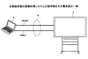
図2は、本実施形態の画像処理システムの使用例を示す概念図の一例である。以下、図示するように、ノートPC6と、電子黒板2とが接続される例で説明する。具体的には、この例では、ノートPC6と、電子黒板2とは、2つのケーブル10で接続されるとする。例えば、このケーブル10のうち、一方のケーブルがUSBケーブル10USBであり、他方のケーブルが映像表示用ケーブル10IMGである。 FIG. 2 is an example of a conceptual diagram showing an example of using the image processing system of the present embodiment. Hereinafter, as illustrated, an example in which the
USBケーブル10USBは、タッチパネル用のケーブルの一例である。すなわち、電子黒板2に対して電子ペン4等を用いてユーザが描画すると、描画の際に電子黒板2がタッチされた位置等を示すデータが、USBケーブル10USBによって、電子黒板2からノートPC6に送られる。 The USB cable 10USB is an example of a cable for a touch panel. That is, when the user draws on the
映像表示用ケーブル10IMGは、ノートPC6が表示する資料等を電子黒板2に表示させるためのデータを送る。すなわち、映像表示用ケーブル10IMGは、ノートPC6から電子黒板2に画像データを送る。 The video display cable 10IMG sends data for displaying materials and the like displayed by the
したがって、図示する構成では、ノートPC6に表示される画面と、電子黒板2に表示される2つの画面がある。以下、このように、2つの画面がある例で説明する。 Therefore, in the illustrated configuration, there are two screens, one displayed on the
電子黒板2を利用するのに、例えば、セキュリティを重視するユーザは、セキュリティポリシが適用された装置でないと使用することができない場合がある。具体的には、通信機能を持つ装置には、特定のセキュリティソフトがインストールされていないと、ユーザは装置を使用できない等である。このような場合において、ユーザは、電子黒板2を利用するのに用いるアプリケーションプログラム(以下単に「アプリケーション」という。)をPCにインストールして電子黒板2を利用する。 To use the
すなわち、図示する例では、セキュリティポリシが適用された装置がノートPC6であるとすると、ノートPC6にアプリケーションをインストールすることで、ユーザは、電子黒板2が有する各機能を利用できる。例えば、アプリケーションに取り込まれた画像は、アプリケーションによって、電子黒板に表示される。なお、アプリケーションによって提供される各機能を利用するため、ノートPCは、アプリケーション画面を表示する。そして、ユーザがアプリケーション画面に対して操作を入力すると、ノートPCは、電子黒板に表示させる画面を変更する等ができる。 That is, in the illustrated example, assuming that the device to which the security policy is applied is the
このようにして、利用できるようになる機能は、例えば、キャプチャの機能である。例えば、ユーザは、真っ白な画面の電子黒板2に対して描画することができる。一方で、ユーザが用意した資料をノートPC6がキャプチャして、電子黒板2に表示させ、表示された資料に対して、ユーザは、電子黒板2上で描画することができる。なお、資料は、例えば、パワーポイント(登録商標)等のプレゼンテーションプログラムで生成されたデータ等である。 The function that becomes available in this way is, for example, the capture function. For example, the user can draw on the
また、画像処理システムは、以下に示すような構成で使用されてもよい。 Further, the image processing system may be used in the configuration shown below.
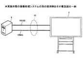
図3は、本実施形態の画像処理システムの別の使用例を示す概念図の一例である。図2と比較すると、図3に示す例では、ノートPC6が、いわゆるデスクトップPCである点が異なる。すなわち、画像処理装置は、ノートPCに限られず、タブレット等又は図示するようなデスクトップPC等の他の情報処理装置でもよい。 FIG. 3 is an example of a conceptual diagram showing another usage example of the image processing system of the present embodiment. Compared with FIG. 2, in the example shown in FIG. 3, the
<ハードウェア構成例>
電子黒板2は、例えば、以下に示すハードウェア構成である。<Hardware configuration example>
The
図4は、本実施形態の画像表示装置のハードウェア構成図の一例である。図示するように、電子黒板2は、例えば、GPU(Graphics Processing Unit)112、ディスプレイコントローラ113、ディスプレイ3、接触センサ115及びセンサコントローラ114を有する。 FIG. 4 is an example of a hardware configuration diagram of the image display device of the present embodiment. As shown in the figure, the
GPU112は、画像処理に係る演算並びに制御を行う演算装置及び制御装置である。 The
ディスプレイコントローラ113は、GPU112から出力される出力画像をディスプレイ3に表示するための画面表示の制御並びに演算を行う演算装置及び制御装置である。 The
ディスプレイ3は、ノートPC6等から入力される画像等の表示画像を表示する出力装置である。 The display 3 is an output device that displays a display image such as an image input from a
センサコントローラ114は、接触センサ115から入力されるセンサデータから座標値を算出する等の演算を行う演算装置である。 The sensor controller 114 is an arithmetic unit that performs calculations such as calculating coordinate values from sensor data input from the
接触センサ115は、手H等が接触したこと及び手Hが接触した位置等を検出するセンサである。例えば、接触センサ115は、赤外線遮断方式によって、手Hが接触した位置を検出して、手Hが接触した位置を座標値で示すセンサデータを出力する。具体的には、赤外線遮断方式では、まず、ディスプレイ3のそれぞれの上側両端部に設置される2つの受発光装置が、ディスプレイ3に対して平行に複数の赤外線を照射する。次に、照射された赤外線は、ディスプレイ3の周辺に設けられる反射部材によって反射する。続いて、受光素子が、反射する赤外線を受光する。そして、接触センサ115は、手H等の物体によって遮断された受発光装置が照射した赤外線のID(Identification)をセンサコントローラ114に出力する。このようにすると、センサコントローラ114は、赤外線のIDに基づいて、物体が接触した位置を座標値で示すことができる。 The
バス120は、各ハードウェアを電気的に接続する。すなわち、バス120は、いわゆるアドレスバス及びデータバス等である。 The
なお、電子黒板2は、図示するハードウェア構成に限られない。例えば、電子黒板2は、演算装置、制御装置及び記憶装置等の装置を更に有してもよい。 The
また、ノートPC6は、例えば、以下に示すハードウェア構成である。 Further, the
図5は、本実施形態の画像処理装置のハードウェア構成図の一例である。 FIG. 5 is an example of a hardware configuration diagram of the image processing device of the present embodiment.
ノートPC6は、主要な構成として、CPU(Central Processing Unit)101、ROM(Read Only Memory)102、RAM(Random Access Memory)103、補助記憶装置104、記録媒体読取装置105、入力装置106、表示装置107及び通信装置108を含む構成である。以下、簡潔に説明する。 The
CPU101は、マイクロプロセッサ及びその周辺回路から構成され、ノートPC6全体を制御する回路である。また、ROM102は、CPU101で実行される所定の制御プログラム(ソフトウェア部品)を格納するメモリであり、RAM103は、CPU101がROM102に格納された所定の制御プログラム(ソフトウェア部品)を実行して各種の制御を行うときの作業エリア(ワーク領域)として使用するメモリである。 The
補助記憶装置104は、汎用のOS、機器情報及びファイアウォールに関する設定情報を含む各種情報を格納する装置であり、不揮発性の記憶装置であるHDD(Hard Disk Drive)等が用いられる。なお、上記各種情報は、補助記憶装置104以外にも、CD−ROM(Compact Disk − Read−Only Memory)若しくはDVD(Digital Versatile Disk)等の記録媒体又はその他のメディアを記憶されてもよい。これらの記録媒体に格納された各種情報は、記録媒体読取装置105等のドライブ装置を介して、コンピュータが読み取ることが可能である。また、必要に応じて記録媒体を記録媒体読取装置105にセットすることで、コンピュータは、各種情報が得られる。 The
入力装置106は、ユーザが各種入力操作を行うための装置である。入力装置106は、マウス、キーボード及び表示装置107の表示画面上に重畳するように設けられたタッチパネルスイッチ等を含む。また、入力装置106は、電子黒板等の外部装置からケーブル等を介してデータを取得するコネクタ等のインタフェースである。表示装置107は、例えば、LCD(Liquid Crystal Display)又はCRT(Cathode Ray Tube)等から構成される。通信装置108は、ネットワークを介して、外部装置との通信を行う装置である。通信装置108は、有線ネットワーク及び無線ネットワーク等を含む各種ネットワーク形態に応じた通信をサポートする。 The
<機能構成例>
ノートPC6にアプリケーションがインストールされると、例えば、ノートPC6は、以下のような機能構成となる。<Function configuration example>
When the application is installed on the
図6は、本実施形態の画像処理装置の機能構成図の一例である。図示するように、ノートPC6は、クライアント部20及び表示部29を備える。また、クライアント部20は、座標検出部22、イベント振分部25、操作処理部26、ジェスチャ処理部27、画像処理部30及び通信制御部60を備える。 FIG. 6 is an example of a functional configuration diagram of the image processing apparatus of the present embodiment. As shown in the figure, the
座標検出部22は、電子黒板2から入力される座標値を示すデータを取得する。例えば、座標検出部22は、入力装置106(図5)又は通信装置108(図5)等によって実現される。 The coordinate
イベント振分部25は、座標検出部22によって取得されるデータ、すなわち、座標値に基づいて、電子黒板2に対して入力された操作をストローク描画、UI(User Intefface)操作又はジェスチャ操作のいずれかのイベントに振り分ける。例えば、イベント振分部25は、CPU101(図5)等によって実現される。 The
なお、ストローク描画は、電子黒板2上にストローク画像が表示されている場合において、ユーザが電子黒板2を手H等で押してから、押した状態で手Hを電子黒板2上で移動させ、その後、押した手Hを電子黒板2から離すまでのイベントである。例えば、ストローク描画によって、アルファベットの「S」又は「T」等の文字が、電子黒板2上に描画される。なお、ストローク描画には、描画した文字等の画像を削除したり、編集したりするイベントが含まれる。 In the stroke drawing, when the stroke image is displayed on the
また、ジェスチャ操作は、電子黒板2上にストローク画像が表示されている場合において、ユーザが表示されている画像に対して、手Hで変更するイベントである。例えば、ジェスチャ操作によって、表示されている画像の拡大、縮小、表示領域の変更、ページ切り替え又はこれらの組み合わせ等が行われる。 Further, the gesture operation is an event in which the stroke image is displayed on the
さらに、UI操作は、電子黒板2上に表示されるUIに対する操作である。 Further, the UI operation is an operation for the UI displayed on the
操作処理部26は、イベント振分部25によって、UI操作に振り分けられるイベントが発生すると、操作の対象となるUIの種類に基づいて処理を行う。なお、UIの種類は、例えば、ボタン、リスト、チェックボックス又はテキストボックス等である。例えば、操作処理部26は、CPU101(図5)等によって実現される。 When an event to be distributed to a UI operation occurs by the
ジェスチャ処理部27は、イベント振分部25によって、ジェスチャ操作に振り分けられるイベントが発生すると、ジェスチャの種類に基づいて処理を行う。具体的には、拡大のジェスチャ操作が入力された場合には、ジェスチャ処理部27は、ジェスチャの対象となる画像を拡大する処理を行う。例えば、ジェスチャ処理部27は、CPU101(図5)等によって実現される。 When an event to be distributed to a gesture operation occurs by the
画像処理部30は、画像取得部31、ストローク処理部32、UI画像生成部33、背景生成部34、レイアウト管理部35、表示重畳部36、ページデータ記憶部300、ファイル処理部40及び遠隔ライセンス管理テーブル310を備える。 The
画像取得部31は、外部装置から取得される映像が示す各フレームを画像として取得する。また、画像取得部31は、画像データをページ処理部37に出力する。この画像は、映像出力機器(ノートPC6等)からの出力画像である。 The
ストローク処理部32は、イベント振分部25によってストローク描画に振り分けられるイベントが発生すると、ストロークに基づいて、画像を描画したり、削除したり、編集したりする。このストローク描画に基づいて生成される画像が、ストローク画像となる。 When an event distributed to stroke drawing by the
UI画像生成部33は、電子黒板2にあらかじめ設定されるUI、すなわち、アイコン等の画像を生成する。 The UI image generation unit 33 generates a UI preset on the
背景生成部34は、ページ処理部37によってページデータ記憶部300から読み出されるページデータのうち、メディアデータをページ処理部37から受信する。そして、背景生成部34は、受信するメディアデータを表示重畳部36に出力する。なお、背景は、例えば、無地又はグリッド等である。 The background generation unit 34 receives media data from the page processing unit 37 among the page data read from the page
レイアウト管理部35は、画像取得部31、ストローク処理部32、UI画像生成部33又は背景生成部34から表示重畳部36に出力される各画像のレイアウトを管理する。このように、レイアウト管理部35がレイアウトを管理することによって、レイアウト管理部35は、出力画像及びストローク画像を、UI画像及び背景画像のうち、どこに表示させるか又は非表示とするか等を指示することができる。 The
表示重畳部36は、レイアウト管理部35からのレイアウトに基づく指示に従って、画像取得部31、ストローク処理部32、UI画像生成部33又は背景生成部34から出力される各画像のレイアウトを行う。 The
また、ページ処理部37は、記憶されるページデータのうち、ストローク配列データ(各ストロークデータ)をストローク処理部32に出力することで、ストロークを再び編集できる状態にする。さらに、ページ処理部37は、記憶されるページデータを削除したり、複製したりする。 Further, the page processing unit 37 outputs the stroke arrangement data (each stroke data) among the stored page data to the
まず、ページ処理部37がページデータ記憶部300にページデータを記憶すると、ディスプレイ上に表示される出力画像のデータは、ページデータ記憶部300に記憶される。そして、ページデータ記憶部300から読み出される場合には、出力画像のデータは、背景を示すメディアデータとして読み出される。次に、ページ処理部37は、ページデータ記憶部300から読み出されるページデータのうち、ストローク画像を示すストローク配列データをストローク処理部32に出力する。また、ページ処理部37は、ページデータ記憶部300から読み出されるページデータのうち、背景を示すメディアデータを背景生成部34に出力する。 First, when the page processing unit 37 stores page data in the page
表示重畳部36は、画像取得部31から出力される出力画像、ストローク処理部32から出力されるストローク画像、UI画像生成部33から出力されるUI画像及び背景生成部34から出力される背景画像を、レイアウト管理部35からのレイアウトに基づく指示に従って重畳する。このようにすると、表示重畳部36は、各画像が重畳されてもユーザが各画像を見ることができる順に出力画像、ストローク画像、UI画像及び背景画像を重畳するレイヤとすることができる。 The
ファイル処理部40は、USBメモリ5等の外部装置から入力されるデータ又はUSBメモリ5等の外部装置に対してデータを出力する処理を行う。すなわち、ファイル処理部40は、USBメモリ5等に対してファイルを入出力する。なお、入力されるファイルは、ページデータ記憶部300に記憶される。また、出力されるファイルは、ページデータ記憶部300から読み出される。例えば、ファイル処理部40は、入力装置106(図5)等によって実現される。 The file processing unit 40 performs a process of outputting data to data input from an external device such as a USB memory 5 or to an external device such as the USB memory 5. That is, the file processing unit 40 inputs / outputs a file to / from the USB memory 5 or the like. The input file is stored in the page
遠隔ライセンス管理テーブル310は、通信ネットワーク9等を介して接続される外部装置と通信を行うのに用いるライセンスを管理する。例えば、遠隔ライセンス管理テーブル310は、補助記憶装置104(図5)等によって実現される。 The remote license management table 310 manages licenses used for communicating with an external device connected via a communication network 9 or the like. For example, the remote license management table 310 is realized by an auxiliary storage device 104 (FIG. 5) or the like.
表示部29は、ディスプレイ等の出力装置又は接続される外部装置に対して、表示重畳部36が生成する画像を表示する。例えば、表示部29は、表示装置107(図5)等によって実現される。 The
通信制御部60は、通信ネットワーク9を介して、外部装置と通信を行い、データを送受信する。例えば、通信制御部60は、通信装置108(図5)等によって実現される。 The
さらに、クライアント部20は、取込部201、取得部202、キャプチャ部203及び判別部204を備える。 Further, the
キャプチャ部203は、表示部29が表示する画面を示す画像データを生成する。すなわち、キャプチャ部203は、いわゆるデスクトップ画面等をキャプチャして、デスクトップ画面を示す画像データを生成する。例えば、キャプチャ部203は、CPU101(図5)等によって実現される。 The
また、ノートPC6上に、文書データ又はプレゼンテーションデータ等が表示されている場合には、キャプチャ部203は、文書データ又はプレゼンテーションデータ等の資料データに基づいて表示される資料を示す画面をキャプチャして画像データを生成する。つまり、電子黒板2に表示させたい資料がある場合には、まず、ユーザは、ノートPC6上に、資料が表示されるように操作する。そして、ノートPC6上に資料が表示されている状態で、ユーザは、キャプチャ部203にキャプチャを実行させる操作を入力する。このようにすると、キャプチャによって、資料を示す画像データが生成される。 Further, when the document data or the presentation data or the like is displayed on the
取込部201は、キャプチャ部203が生成する画像データを取り込み、電子黒板2上に、画像データに基づく画像(以下「第1画像」という。)が表示されるようにする。すなわち、取込部201は、デスクトップ画面等を示す第1画像を電子黒板2に表示させる。例えば、取込部201は、CPU101(図5)等によって実現される。 The
具体的には、取込部201は、あらかじめノートPC6にインストールされるアプリケーションを介して、電子黒板2に第1画像を表示させる。次に、電子黒板2は、ユーザから、第1画像に対して文字等を書き込む操作を受け付ける。そして、電子黒板2は、書込と、第1画像とを一体にした画像(以下「第2画像」という。)を表示する。つまり、例えば、まず、電子黒板2は、キャプチャされた資料等を示す第1画像を背景として表示する。次に、ユーザによって、資料等に対してコメント等が書き込まれると、電子黒板2は、資料等を示し、かつ、コメント等の書込も示す第2画像を表示することができる。なお、操作によって書き込まれるコメント等を示すストローク画像は、ストローク処理部32等によって生成される。そして、第2画像は、第1画像に、ストローク画像を重畳させて一体にした画像である。 Specifically, the
また、例えば、アプリケーションを介さず、電子黒板2が第1画像を表示する比較例と比較すると、まず、アプリケーションを介すと、電子黒板2は、ユーザの手書きによる書き込み等の操作を受け付けることができる。一方で、比較例では、電子黒板2は、書き込み等の操作を受け付けることができない場合が多い。すなわち、比較例は、第1画像を表示することはできても、第1画像に対する書き込み等の操作を受け付けるのが難しい。 Further, for example, as compared with the comparative example in which the
これに対して、取込部201等を有する構成とすると、ノートPC6は、書き込み等の操作を受け付けることができ、資料等を示す第1画像に、ユーザによる書込を示すストローク画像を重畳させた第2画像を表示することができる効果を奏する。 On the other hand, if the
取得部202は、第1画面と、第2画面とを識別するデータ(以下「識別データ」という。)を取得する。なお、取得部202は、例えば、入力装置106(図5)等によって実現される。また、識別データは、例えば、EDID(Extended display identification data)等である。まず、以下に、第1画面及び第2画面の一例を説明する。 The
<画面例及び設定例>
以下、ノートPCのOS(Operating System)がWindows(登録商標)である例で説明する。なお、実施形態は、OSがWindows(登録商標)である場合に限られない。すなわち、OSは、Windows(登録商標)以外の種類でもよい。<Screen example and setting example>
Hereinafter, an example in which the OS (Operating System) of a notebook PC is Windows (registered trademark) will be described. The embodiment is not limited to the case where the OS is Windows (registered trademark). That is, the OS may be of a type other than Windows (registered trademark).
以下の説明は、ノートPCに対して複数のディスプレイが接続される場合であるとする。例えば、図2に示すように、ノートPC6に対して電子黒板2が接続される場合である。すなわち、ノートPC6は、ノートPC6が有する表示装置107(図5)と、電子黒板2が有するディスプレイ3(図4)とを認識し、どちらの画面に対しても画面を表示する。そして、ノートPCには、各ディスプレイに同一の画面をそれぞれ表示する(以下「複製」という。)か又は各ディスプレイに異なる画面をそれぞれ表示する(以下「拡張」という。)かが設定できる。具体的には、OSがWindows7(登録商標)である場合には、「画面の解像度」の設定における「複数のディスプレイ」のプルダウンメニューにある「表示画面を拡張する」及び「表示画面を複製する」をユーザが選んで設定ことができる。例えば、設定と、各ディスプレイに表示される画面は、以下のような関係となる。 The following description assumes that a plurality of displays are connected to the notebook PC. For example, as shown in FIG. 2, the
図7は、本実施形態の画像処理装置によって表示される画面を示す図の一例である。図示する表において、上段(図内では「複製」と示す段である。)は、ノートPCに「複製」の設定がされる場合に、各ディスプレイに表示される画面の例を示す。一方で、図示する表において、下段(図内では「拡張」と示す段である。)は、ノートPCに「拡張」の設定がされる場合に、各ディスプレイに表示される画面の例を示す。 FIG. 7 is an example of a diagram showing a screen displayed by the image processing apparatus of the present embodiment. In the illustrated table, the upper row (in the figure, the row indicated by “duplicate”) shows an example of the screen displayed on each display when the notebook PC is set to “duplicate”. On the other hand, in the illustrated table, the lower row (the row indicated as "extended" in the figure) shows an example of the screen displayed on each display when the notebook PC is set to "extended". ..
以下、ノートPCが有するディスプレイに表示される画面を「第1画面」という。一方で、図2のように、ノートPCに対して電子黒板2が接続される場合の例において、電子黒板2が有するディスプレイ3に表示される画面を「第2画面」という。 Hereinafter, the screen displayed on the display of the notebook PC is referred to as a "first screen". On the other hand, in an example in which the
図2で説明するように、ノートPCにアプリケーションがインストールされると、ノートPCは、例えば、図7に示すようなアプリケーション画面APPを表示することができる。このアプリケーション画面APPに対してユーザが操作を入力すると、ユーザは、ノートPCに対して操作を入力することで、電子黒板2を利用することができる。 As will be described in FIG. 2, when the application is installed in the notebook PC, the notebook PC can display the application screen APP as shown in FIG. 7, for example. When the user inputs an operation to the application screen APP, the user can use the
図7に戻り、図示するように、設定によって、ノートPCは、第1画面と、第2画面とに表示される画面を同一とするか異なる画面とするかを変えることができる。具体的には、図示する例において「複製」の設定では、ノートPCは、第1画面及び第2画面にそれぞれアプリケーション画面APPをそれぞれ表示する。この設定では、第1画面と、第2画面とに表示される画面が同一とされるため、例えば、第1画面が表示するアプリケーション画面APPが操作を入力すると、同様の操作が行われた画面が、第2画面にも表示される。 Returning to FIG. 7, as shown in the figure, the notebook PC can change whether the screens displayed on the first screen and the second screen are the same or different depending on the settings. Specifically, in the illustrated example, in the "duplicate" setting, the notebook PC displays the application screen APP on the first screen and the second screen, respectively. In this setting, the screens displayed on the first screen and the second screen are the same. Therefore, for example, when the application screen APP displayed on the first screen inputs an operation, the screen on which the same operation is performed is performed. Is also displayed on the second screen.
一方で、図示する例において「拡張」の設定では、ノートPCは、第1画面には、デスクトップ画面DSKを表示し、第2画面には、アプリケーション画面APPをそれぞれ表示する。以下、図示するような「拡張」の設定が、ノートPCに対してされた場合を例に説明する。 On the other hand, in the illustrated example, in the "extended" setting, the notebook PC displays the desktop screen DSK on the first screen and the application screen APP on the second screen. Hereinafter, a case where the “extended” setting as shown in the figure is set for the notebook PC will be described as an example.
この例では、第1画面には、デスクトップ画面DSKが表示され、ユーザは、デスクトップ画面DSKに対して操作を入力することで、インストールされているプログラム等を用いて、文書を作成したり、画像を編集したりする等の操作を行うことができる。なお、第1画面に表示される画面が、電子黒板2が有するディスプレイ3には表示されない。そのため、ノートPCに接するユーザは、第1画面で作業中の画面又は秘密のデータ等が表示されている画面等をノートPCに接するユーザ以外の者に見られることなく操作を行うことができる。 In this example, the desktop screen DSK is displayed on the first screen, and the user can input an operation to the desktop screen DSK to create a document or create an image using the installed program or the like. You can perform operations such as editing. The screen displayed on the first screen is not displayed on the display 3 of the
一方で、第2画面に表示される画面は、ノートPCに接するユーザも、電子黒板2を見る会議の参加者等にもアプリケーション画面APPによって表示される。そのため、第2画面にアプリケーション画面APPによって情報を表示して情報共有等を行うことができる。 On the other hand, the screen displayed on the second screen is displayed by the application screen APP to both the user who is in contact with the notebook PC and the participants of the conference who see the
また、「拡張」の設定では、ツールバー等のGUI(Graphical User Interface、以下「グラフィックユーザインタフェース」という場合もある。)は、ユーザの操作に基づいて、第1画面と、第2画面との間を移動することができる。すなわち、「拡張」の設定では、ユーザは、第1画面と、第2画面とがつながった1つの画面のように操作することができる。例えば、ユーザは、デスクトップ画面DSK側で表示されるアイコンをいわゆるドラッグアンドドロップ等の操作によって、アプリケーション画面APP側に移動させることができる。 Further, in the "extended" setting, a GUI (Graphical User Interface, hereinafter may also be referred to as "graphic user interface") such as a toolbar is placed between the first screen and the second screen based on the user's operation. Can be moved. That is, in the "extended" setting, the user can operate as if the first screen and the second screen are connected to each other. For example, the user can move the icon displayed on the desktop screen DSK side to the application screen APP side by an operation such as so-called drag and drop.
そして、ノートPCを操作するユーザが用意した資料をキャプチャし、キャプチャした画像を電子黒板に表示させる場合がある。以下、「複製」の設定がされた場合と、「拡張」の設定がされた場合のそれぞれの例を説明する。 Then, the material prepared by the user who operates the notebook PC may be captured and the captured image may be displayed on the electronic blackboard. Hereinafter, examples of the case where "duplicate" is set and the case where "extended" is set will be described.
図8は、本実施形態の画像処理装置に対して「複製」の設定がされた場合の画面を示す図の一例である。図は、ノートPCに対して「複製」の設定がされた場合に、各画面に表示される画面の例を示す。 FIG. 8 is an example of a diagram showing a screen when "reproduction" is set for the image processing apparatus of the present embodiment. The figure shows an example of a screen displayed on each screen when "duplicate" is set for the notebook PC.
以下、ユーザがノートPCから電子黒板を利用する、すなわち、アプリケーション画面APPが表示される場合を「ホワイトボードモード」という。一方で、ユーザがノートPCにおいて電子黒板を利用する以外の操作を行う、すなわち、アプリケーション画面APPが最小化され、かつ、デスクトップ画面DSKが表示される場合を「デスクトップモード」という。 Hereinafter, the case where the user uses the electronic blackboard from the notebook PC, that is, the application screen APP is displayed is referred to as "whiteboard mode". On the other hand, the case where the user performs an operation other than using the electronic blackboard on the notebook PC, that is, the application screen APP is minimized and the desktop screen DSK is displayed is called "desktop mode".
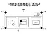
また、ノートPCは、キャプチャによって、電子黒板に表示される画像(以下「表示画像」という。)を生成する。そして、表示画像を生成する指示、すなわち、キャプチャを実行させる操作をユーザが入力すると、ノートPCは、キャプチャを行う。そのため、ノートPCは、この指示をユーザに入力させるGUIを表示する。例えば、このGUIは、以下に示すようなツールバーCAPである。以下、ホワイトボードモードにおいて表示されるツールバーCAPの例を説明する。 Further, the notebook PC generates an image displayed on the electronic blackboard (hereinafter referred to as "display image") by capture. Then, when the user inputs an instruction to generate a display image, that is, an operation for executing the capture, the notebook PC performs the capture. Therefore, the notebook PC displays a GUI that causes the user to input this instruction. For example, this GUI is a toolbar CAP as shown below. Hereinafter, an example of the toolbar CAP displayed in the whiteboard mode will be described.
図9は、本実施形態の画像処理装置が表示するアプリケーション画面及びGUIを示す図の一例である。図示する例は、ホワイトボードモードでは、アプリケーション画面APP上に、ツールバーCAPがノートPCによって表示される例である。なお、ツールバーCAPは、ユーザによるドラッグアンドドロップ等の操作によって、表示する位置を変更することができる。また、ツールバーCAPは、アプリケーション画面APP上に表示される、いわゆる、最前面に表示されるのが望ましい。以下、ツールバーCAPの詳細を説明する。 FIG. 9 is an example of a diagram showing an application screen and a GUI displayed by the image processing apparatus of the present embodiment. In the illustrated example, in the whiteboard mode, the toolbar CAP is displayed by the notebook PC on the application screen APP. The toolbar CAP can be changed in display position by an operation such as drag and drop by the user. Further, it is desirable that the toolbar CAP is displayed on the application screen APP, that is, so-called foreground. The details of the toolbar CAP will be described below.
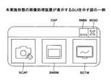
図10は、本実施形態の画像処理装置が表示するGUIを示す図の一例である。すなわち、図10は、図9におけるツールバーCAPを大きくして示す図である。図示するように、ツールバーCAPは、例えば、最小化ボタンBMIN、終了ボタンBEND、キャプチャボタンBCAP、ホワイトボードボタンBWBM及びデスクトップモードボタンBDTMを有する。 FIG. 10 is an example of a diagram showing a GUI displayed by the image processing apparatus of the present embodiment. That is, FIG. 10 is a diagram showing an enlarged toolbar CAP in FIG. As shown, the toolbar CAP has, for example, a minimize button BMIN, an end button BEND, a capture button BCAP, a whiteboard button BWBM and a desktop mode button BDTM.
以下、ツールバーCAPに対してユーザが操作を行うと、下記の処理が行われる例で説明する。 Hereinafter, the following processing will be described as an example when the user operates the toolbar CAP.
(1)デスクトップ画面DSK(図7等)に表示される画面をキャプチャして表示画面を生成し、生成された表示画面がアプリケーション画面APPに取り込まれる処理
(2)ホワイトボードモードと、デスクトップモードとを切り替える処理
(3)ツールバーCAPを最小化させる(タスクバーに入れる)処理
(4)アプリケーションを終了させる処理
ツールバーCAPが有するボタンが押下されると、ノートPCは、上記(1)乃至(4)の処理を以下のようにして実行する。(1) Processing to capture the screen displayed on the desktop screen DSK (Fig. 7, etc.) to generate a display screen, and the generated display screen is imported into the application screen APP (2) Whiteboard mode and desktop mode Processing to switch (3) Processing to minimize the toolbar CAP (put it in the taskbar) (4) Processing to terminate the application When the button of the toolbar CAP is pressed, the notebook PC is subjected to the above (1) to (4). Execute the process as follows.
最小化ボタンBMINが押下されると、ノートPCは、ツールバーCAPと、アプリケーション画面APPとを最小化させる。すなわち、ノートPCは、ツールバーCAPと、アプリケーション画面APPとをいわゆるタスクバーに収納する。このようにして、最小化ボタンBMINが押下されると、ノートPCは、上記(3)の処理を行う。 When the minimize button BMIN is pressed, the notebook PC minimizes the toolbar CAP and the application screen APP. That is, the notebook PC stores the toolbar CAP and the application screen APP in the so-called task bar. In this way, when the minimize button BMIN is pressed, the notebook PC performs the process (3) above.
終了ボタンBENDが押下されると、ノートPCは、アプリケーションを終了させる。このようにして、終了ボタンBENDが押下されると、ノートPCは、上記(4)の処理を行う。 When the end button BEND is pressed, the notebook PC terminates the application. In this way, when the end button BEND is pressed, the notebook PC performs the process (4) above.
ホワイトボードボタンBWBM又はデスクトップモードボタンBDTMのどちらかが押下されると、ノートPCは、ホワイトボードモードと、デスクトップモードとを切り替える。具体的には、ホワイトボードモードにおいて、デスクトップモードボタンBDTMが押下されると、ノートPCは、ホワイトボードモードからデスクトップモードに切り替える。一方で、デスクトップモードにおいて、ホワイトボードボタンBWBMが押下されると、ノートPCは、デスクトップモードからホワイトボードモードに切り替える。このようにして、ホワイトボードボタンBWBM又はデスクトップモードボタンBDTMが押下されると、ノートPCは、上記(2)の処理を行う。 When either the whiteboard button BWBM or the desktop mode button BDTM is pressed, the notebook PC switches between the whiteboard mode and the desktop mode. Specifically, in the whiteboard mode, when the desktop mode button BDTM is pressed, the notebook PC switches from the whiteboard mode to the desktop mode. On the other hand, in the desktop mode, when the whiteboard button BWBM is pressed, the notebook PC switches from the desktop mode to the whiteboard mode. In this way, when the whiteboard button BWBM or the desktop mode button BDTM is pressed, the notebook PC performs the process (2) above.
キャプチャボタンBCAPが押下されると、ノートPCは、第1画面又は第2画面(図7及び図8)のいずれか一方の画面を選択して、選択された画面を示す表示画像を生成する。すなわち、キャプチャボタンBCAPが押下されると、ノートPCは、上記(1)の処理を行う。なお、図8に示すように、「複製」である場合には、第1画面と、第2画面とは、ホワイトボードモードであっても、デスクトップモードであっても同一の画面であるため、どちらの画面が選択されても、表示画像は、同様の画像となる。 When the capture button BCAP is pressed, the notebook PC selects either the first screen or the second screen (FIGS. 7 and 8) to generate a display image showing the selected screen. That is, when the capture button BCAP is pressed, the notebook PC performs the process (1) above. As shown in FIG. 8, in the case of "duplicate", the first screen and the second screen are the same screen regardless of whether they are in the whiteboard mode or the desktop mode. Whichever screen is selected, the displayed image will be the same image.
一方で、以下のように、「拡張」の設定がされる場合がある。 On the other hand, "extended" may be set as follows.
図11は、本実施形態の画像処理装置に対して「拡張」の設定がされた場合の画面を示す図の一例である。図は、ノートPCに対して「拡張」の設定がされた場合に、各画面に表示される画面の例を示す。図7で説明するように、「拡張」の設定がされると、ノートPCは、第1画面と、第2画面とでそれぞれ異なる画面を表示する。図示するように、ホワイトボードモードでは、例えば、第1画面に、デスクトップ画面DSKが表示され、第2画面に、アプリケーション画面APPが表示される。 FIG. 11 is an example of a diagram showing a screen when "extended" is set for the image processing device of the present embodiment. The figure shows an example of a screen displayed on each screen when "extended" is set for the notebook PC. As described with reference to FIG. 7, when the "extended" setting is made, the notebook PC displays different screens for the first screen and the second screen. As shown in the figure, in the whiteboard mode, for example, the desktop screen DSK is displayed on the first screen, and the application screen APP is displayed on the second screen.
一方で、図示するように、デスクトップモードでは、例えば、第1画面にも、第2画面にもデスクトップ画面が表示される。ただし、第1画面に表示されるデスクトップ画面(以下「第1デスクトップ画面DSK1」という。)と、第2画面に表示されるデスクトップ画面(以下「第2デスクトップ画面DSK2」という。)とは、異なる画面である。すなわち、「拡張」の設定がされ、かつ、デスクトップモードであると、ユーザの操作に基づいて、ノートPCは、第1デスクトップ画面DSK1と、第2デスクトップ画面DSK2とに異なる資料をノートPCにそれぞれ表示させること等ができる。特に、「拡張」の設定がされ、かつ、デスクトップモードでは、ユーザは、キャプチャの対象を第1デスクトップ画面DSK1又は第2デスクトップ画面DSK2から選択したい場合が多い。 On the other hand, as shown in the figure, in the desktop mode, for example, the desktop screen is displayed on both the first screen and the second screen. However, the desktop screen displayed on the first screen (hereinafter referred to as "first desktop screen DSK1") and the desktop screen displayed on the second screen (hereinafter referred to as "second desktop screen DSK2") are different. It is a screen. That is, when the "extended" setting is made and the desktop mode is set, the notebook PC uses different materials for the first desktop screen DSK1 and the second desktop screen DSK2 based on the user's operation. It can be displayed, etc. In particular, in the "extended" setting and in the desktop mode, the user often wants to select the capture target from the first desktop screen DSK1 or the second desktop screen DSK2.
そこで、ノートPCは、第1画面又は第2画面のうち、どちらの画面を選択する、すなわち、キャプチャの対象とするかを、例えば、ツールバーCAP(図10)が表示される位置等で判定してもよい。具体的には、ノートPCは、以下のような処理で判定を行う。 Therefore, the notebook PC determines which screen to select from the first screen or the second screen, that is, the target of capture, for example, at the position where the toolbar CAP (FIG. 10) is displayed. You may. Specifically, the notebook PC makes a determination by the following processing.
図12は、本実施形態の画像処理装置による判定処理を示すフローチャートの一例である。図示する判定処理は、例えば、ツールバーCAP(図10)がドラッグアンドドロップの操作によって移動されたり、設定又はモードが切り替えられたりすると、ノートPCによって行われる処理である。 FIG. 12 is an example of a flowchart showing the determination process by the image processing apparatus of the present embodiment. The illustrated determination process is, for example, a process performed by the notebook PC when the toolbar CAP (FIG. 10) is moved by a drag-and-drop operation or the setting or mode is switched.
ステップS01では、ノートPCは、設定が「複製」であるか「拡張」であるかを判断する。例えば、ノートPCは、ユーザがあらかじめOS等に設定するディスプレイに係る設定値等を取得して、取得される設定値等から設定が「複製」であるか「拡張」であるかを判断する。次に、設定が「複製」であると、ノートPCは、ステップS02に進む。一方で、設定が「拡張」であると、ノートPCは、ステップS05に進む。 In step S01, the notebook PC determines whether the setting is "duplicate" or "extended". For example, the notebook PC acquires the setting value or the like related to the display set in the OS or the like in advance by the user, and determines whether the setting is "duplicate" or "extended" from the acquired setting value or the like. Next, if the setting is "duplicate", the notebook PC proceeds to step S02. On the other hand, if the setting is "extended", the notebook PC proceeds to step S05.
ステップS02では、ノートPCは、「ホワイトボードモード」であるか「デスクトップモード」であるかを判断する。例えば、図10に示すホワイトボードボタンBWBM又はデスクトップモードボタンBDTMのうち、直近に押下されたボタンがどちらであるか又はOS等の設定等に基づいて、ノートPCは、判断する。次に、「デスクトップモード」であると判断されると、ノートPCは、ステップS03に進む。一方で、「ホワイトボードモード」であると判断されると、ノートPCは、ステップS04に進む。 In step S02, the notebook PC determines whether it is in the "whiteboard mode" or the "desktop mode". For example, the notebook PC determines which of the whiteboard button BWBM or the desktop mode button BDTM shown in FIG. 10 is the most recently pressed button, or the setting of the OS or the like. Next, when it is determined that the "desktop mode" is set, the notebook PC proceeds to step S03. On the other hand, if it is determined that the mode is "whiteboard mode", the notebook PC proceeds to step S04.
ステップS03では、ノートPCは、第1画面に基づいて表示画像を生成する。すなわち、「複製」で設定であり、かつ、「デスクトップモード」である場合に、キャプチャボタンBCAP(図10)が押下されると、ノートPCは、デスクトップ画面DSK(図8)をキャプチャする。より具体的には、ノートPCは、デスクトップ画面DSKを示す画像をRAM103(図5)に記憶する。 In step S03, the notebook PC generates a display image based on the first screen. That is, when the capture button BCAP (FIG. 10) is pressed when the setting is "duplicate" and the "desktop mode" is set, the notebook PC captures the desktop screen DSK (FIG. 8). More specifically, the notebook PC stores an image showing the desktop screen DSK in the RAM 103 (FIG. 5).
ステップS04では、ノートPCは、キャプチャを制限する。例えば、ノートPCは、キャプチャボタンBCAPをグレーアウトさせたりして使用できなくしたり、キャプチャボタンBCAPが押下されてもキャプチャが行われないようにする。 In step S04, the notebook PC limits the capture. For example, the notebook PC grays out the capture button BCAP to make it unusable, or prevents the capture from being performed even if the capture button BCAP is pressed.
設定が「複製」であっても、「拡張」であっても、「ホワイトボードモード」では、ユーザがキャプチャしたいのは、デスクトップ画面DSKであることが多い。それは、アプリケーション画面APP(図7及び図8)に表示されている画面は、既に電子黒板に表示されている画面であるため、再度キャプチャし、電子黒板に表示させる作業を行うことは、少ないためである。 In "whiteboard mode", the user often wants to capture the desktop screen DSK, regardless of whether the setting is "duplicate" or "extended". This is because the screen displayed on the application screen APP (FIGS. 7 and 8) is a screen already displayed on the electronic blackboard, so it is rare to capture it again and display it on the electronic blackboard. Is.
ステップS05では、ノートPCは、ツールバーの座標値を取得する。例えば、ノートPCは、ツールバーCAPが有する所定の箇所が、どこに表示されているかを取得する。 In step S05, the notebook PC acquires the coordinate values of the toolbar. For example, the notebook PC acquires where a predetermined portion of the toolbar CAP is displayed.
図13は、本実施形態の画像処理装置によるGUIが有する所定の箇所を用いる判定処理を示す図の一例である。以下、図示するような第1画面及び第2画面の例で説明する。 FIG. 13 is an example of a diagram showing a determination process using a predetermined portion of the GUI by the image processing apparatus of the present embodiment. Hereinafter, an example of the first screen and the second screen as shown will be described.
まず、この例では、第1画面が、「1280×800」の解像度(いわゆるWXGA)に設定されるとする。一方で、この例では、第2画面が、「1920×1080」の解像度(いわゆるFHD)に設定されるとする。そして、図示するように、第1画面の左上が原点(0、0)に設定されるとする。また、この例では、「拡張」の設定において、第1画面及び第2画面は、図示するように、第1画面の右端と第2画面の左端とがつながっているように設定されるとする。さらに、この例では、ユーザは、ツールバーCAPをドラッグする操作によって、ツールバーCAPを第1画面内、第2画面内及び第1画面と第2画面の間で移動させることができる。なお、第1画面及び第2画面の配置は、図示する配置に限られず、例えば第1画面と第2画面とは逆に配置される等でもよい。 First, in this example, it is assumed that the first screen is set to a resolution of "1280 x 800" (so-called WXGA). On the other hand, in this example, it is assumed that the second screen is set to a resolution of "1920 × 1080" (so-called FHD). Then, as shown in the figure, it is assumed that the upper left of the first screen is set to the origin (0, 0). Further, in this example, in the "extended" setting, it is assumed that the first screen and the second screen are set so that the right end of the first screen and the left end of the second screen are connected as shown in the figure. .. Further, in this example, the user can move the toolbar CAP within the first screen, within the second screen, and between the first screen and the second screen by dragging the toolbar CAP. The arrangement of the first screen and the second screen is not limited to the arrangement shown in the figure, and may be arranged in the opposite direction of the first screen and the second screen, for example.
ステップS05(図12)では、ノートPCは、ツールバーCAPが有する所定の箇所の図13上における座標値を取得する。所定の箇所は、あらかじめ設定される。例えば、所定の箇所は、左上ULの点等である。なお、所定の箇所は、左上ULの点以外でもよい。例えば、所定の箇所は、以下のような点でもよい。 In step S05 (FIG. 12), the notebook PC acquires the coordinate values on FIG. 13 of the predetermined location of the toolbar CAP. A predetermined place is set in advance. For example, a predetermined place is a point of the upper left UL. The predetermined location may be a point other than the upper left UL point. For example, the predetermined location may be the following points.
図14は、本実施形態の画像処理装置によって表示されるGUIが有する所定の箇所を示す図の一例である。例えば、取得される座標値の対象となる所定の箇所は、左上UL以外の四隅の点等である。具体的には、図示するように、所定の箇所は、左下UDの点、右上RLの点又は右下RDの点等である。他にも、所定の箇所は、図心ICの点又はユーザが設定する点等でもよい。 FIG. 14 is an example of a diagram showing a predetermined location of the GUI displayed by the image processing apparatus of the present embodiment. For example, the predetermined points that are the targets of the acquired coordinate values are the points at the four corners other than the upper left UL. Specifically, as shown in the figure, the predetermined location is a lower left UD point, an upper right RL point, a lower right RD point, or the like. In addition, the predetermined location may be a point of the centroid IC, a point set by the user, or the like.
ステップS06では、ノートPCは、各画面に係るデータを取得する。例えば、図13に示す例では、ノートPCは、第1画面及び第2画面の解像度(領域情報)等を示すデータを取得する。これにより、図13に示す例では、ノートPCは、X軸の座標値が「0」乃至「1279」、すなわち、X軸の座標値が「1279」以下の領域は、第1画面であると判定できる。一方で、図13に示す例では、ノートPCは、X軸の座標値が「1280」乃至「3200」、すなわち、X軸の座標値が「1280」以上の領域は、第2画面であると判定できる。 In step S06, the notebook PC acquires data related to each screen. For example, in the example shown in FIG. 13, the notebook PC acquires data indicating the resolution (area information) of the first screen and the second screen. As a result, in the example shown in FIG. 13, in the notebook PC, the area where the X-axis coordinate value is "0" to "1279", that is, the area where the X-axis coordinate value is "1279" or less is the first screen. It can be judged. On the other hand, in the example shown in FIG. 13, in the notebook PC, the area where the X-axis coordinate value is "1280" to "3200", that is, the area where the X-axis coordinate value is "1280" or more is the second screen. It can be judged.
ステップS07では、ノートPCは、キャプチャの対象が第1画面か第2画面かを判断する。例えば、ノートPCは、ステップS05で取得される座標値が、ステップS06で取得されるデータに基づいて、どちらの画面にあるかで判断する。 In step S07, the notebook PC determines whether the capture target is the first screen or the second screen. For example, the notebook PC determines which screen the coordinate value acquired in step S05 is on based on the data acquired in step S06.
具体的には、図13に示す例では、ノートPCは、ステップS05で、左上ULの点の座標値(1158、356)を取得する。次に、ノートPCは、ステップS06で取得されるデータに基づいて、左上ULの点のX座標の座標値が「1279」以下であるか「1280」以上であるか判断する。この場合には、「1158」の座標値は、「1279」以下であるため、第1画面にあると判断される。すなわち、左上ULの点が、図13に示す左側の領域にあると、ノートPCは、第1画面にあると判断する(ステップS07で「第1画面」)。一方で、左上ULの点が、図13に示す右側の領域にあると、ノートPCは、第2画面にあると判断する(ステップS07で「第2画面」)。 Specifically, in the example shown in FIG. 13, the notebook PC acquires the coordinate value (1158, 356) of the point of the upper left UL in step S05. Next, the notebook PC determines whether the coordinate value of the X coordinate of the upper left UL point is "1279" or less or "1280" or more based on the data acquired in step S06. In this case, since the coordinate value of "1158" is "1279" or less, it is determined that the coordinate value is on the first screen. That is, when the point of the upper left UL is in the area on the left side shown in FIG. 13, the notebook PC determines that it is on the first screen (“first screen” in step S07). On the other hand, when the point of the upper left UL is in the area on the right side shown in FIG. 13, the notebook PC determines that it is on the second screen (“second screen” in step S07).
なお、キャプチャの対象が第1画面か第2画面かを判断する方法は、所定の箇所の座標値に限られない。例えば、判断する方法は、以下のようなツールバーCAPの面積を利用する方法でもよい。 The method of determining whether the capture target is the first screen or the second screen is not limited to the coordinate values of the predetermined locations. For example, the method of determining may be a method of using the area of the toolbar CAP as follows.
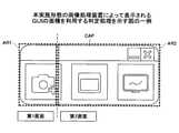
図15は、本実施形態の画像処理装置によって表示されるGUIの面積を利用する判定処理を示す図の一例である。以下、図13に示す例において、ツールバーCAPが表示される面積のうち、第1画面に表示されるツールバーCAPの面積を「第1面積AR1」という。一方で、ツールバーCAPが表示される面積のうち、第2画面に表示されるツールバーCAPの面積を「第2面積AR2」という。例えば、第1面積AR1及び第2面積AR2は、図15のように示せる。図示する例では、第1面積AR1と、第2面積AR2とを比較すると、第2面積AR2の方が、第1面積AR1の方より広い。そのため、ノートPCは、第2画面にあると判断する(図12に示すステップS07で「第2画面」)。 FIG. 15 is an example of a diagram showing a determination process using the area of the GUI displayed by the image processing apparatus of the present embodiment. Hereinafter, in the example shown in FIG. 13, of the areas where the toolbar CAPs are displayed, the area of the toolbar CAPs displayed on the first screen is referred to as "first area AR1". On the other hand, of the area where the toolbar CAP is displayed, the area of the toolbar CAP displayed on the second screen is referred to as "second area AR2". For example, the first area AR1 and the second area AR2 can be shown as shown in FIG. In the illustrated example, when the first area AR1 and the second area AR2 are compared, the second area AR2 is wider than the first area AR1. Therefore, it is determined that the notebook PC is on the second screen (“second screen” in step S07 shown in FIG. 12).
また、判断する方法は、ユーザにどちらをキャプチャ対象とするか入力させる方法でもよい。例えば、キャプチャの際に、ノートPCは、図13に示すいずれかの領域をクリックするようにユーザにメッセージを表示する。次に、この表示に従って、ユーザが、図13に示すいずれかの位置をクリックする操作を入力する。続いて、ステップS05(図12)では、ノートPCは、クリックされた点の座標値を取得する。そして、ステップS07(図12)では、ノートPCは、クリックされた点の座標値がステップS06(図12)で取得されるデータに基づいて、どちらの画面にあるかで判断してもよい。すなわち、ユーザがキャプチャ対象に希望する方の画面の領域をクリックし、クリックされた点の座標値に基づいて、キャプチャ対象が、ノートPCによって判断されてもよい。 Further, the method of determining may be a method of having the user input which one is to be captured. For example, during capture, the notebook PC displays a message to the user to click on any of the areas shown in FIG. Next, according to this display, the user inputs an operation of clicking any position shown in FIG. Subsequently, in step S05 (FIG. 12), the notebook PC acquires the coordinate value of the clicked point. Then, in step S07 (FIG. 12), the notebook PC may determine which screen the coordinate value of the clicked point is on based on the data acquired in step S06 (FIG. 12). That is, the user may click on the area of the screen that is desired to be captured, and the notebook PC may determine the capture target based on the coordinate values of the clicked points.
他にも、ユーザにどちらをキャプチャ対象とするか入力させる方法は、例えば、キャプチャの際に、キャプチャ対象を選択するボタンを表示し、ユーザに入力させる方法でもよい。すなわち、キャプチャの際に、ノートPCは、「キャプチャ対象を第1画面とする」ボタンと、「キャプチャ対象を第2画面とする」ボタンとをそれぞれ表示する。そして、ノートPCは、ボタンが押下された方の画面をキャプチャ対象と判断してもよい。 Alternatively, the method of having the user input which one is to be captured may be, for example, a method of displaying a button for selecting the capture target at the time of capture and letting the user input. That is, at the time of capture, the notebook PC displays a "capture target as the first screen" button and a "capture target as the second screen" button, respectively. Then, the notebook PC may determine that the screen on which the button is pressed is the capture target.
さらに、判断する方法は、X座標値を使用する方法に限られない。例えば、設定等によって、以下のように第1画面及び第2画面がつながる場合がある。 Further, the method of determination is not limited to the method of using the X coordinate value. For example, the first screen and the second screen may be connected as follows depending on the settings and the like.
図16は、本実施形態の画像処理装置によって表示されるY座標値を使用する場合の画面を示す図の一例である。図示するように、第1画面及び第2画面は、図における縦方向、すなわち、Y軸方向につながるような設定がされる場合がある。このような場合等では、ステップS07(図12)では、ノートPCは、ステップS05(図12)で取得される座標値のうち、Y座標値を用いて判断する。 FIG. 16 is an example of a diagram showing a screen when the Y coordinate value displayed by the image processing apparatus of the present embodiment is used. As shown in the figure, the first screen and the second screen may be set so as to be connected in the vertical direction in the figure, that is, in the Y-axis direction. In such a case, in step S07 (FIG. 12), the notebook PC makes a determination using the Y coordinate value among the coordinate values acquired in step S05 (FIG. 12).
図12に戻り、ステップS08では、ノートPCは、「ホワイトボードモード」であるか「デスクトップモード」であるかを判断する。例えば、ステップS08では、ノートPCは、ステップS02と同様の判断を行う。次に、「デスクトップモード」であると判断されると、ノートPCは、ステップS09に進む。一方で、「ホワイトボードモード」であると判断されると、ノートPCは、ステップS04に進む。 Returning to FIG. 12, in step S08, the notebook PC determines whether it is in the “whiteboard mode” or the “desktop mode”. For example, in step S08, the notebook PC makes the same determination as in step S02. Next, when it is determined that the "desktop mode" is set, the notebook PC proceeds to step S09. On the other hand, if it is determined that the mode is "whiteboard mode", the notebook PC proceeds to step S04.
ステップS09では、ノートPCは、第2画面に基づいて表示画像を生成する。すなわち、「拡張」で設定であり、かつ、「デスクトップモード」である場合に、キャプチャボタンBCAP(図10)が押下されると、ノートPCは、ステップS07で判断された方のデスクトップ画面をキャプチャする。具体的には、ステップS09では、ノートPCは、第2デスクトップ画面DSK2(図11)をキャプチャする、すなわち、第2デスクトップ画面DSK2を示す画像をRAM103(図5)に記憶する。 In step S09, the notebook PC generates a display image based on the second screen. That is, when the capture button BCAP (FIG. 10) is pressed when the setting is "extended" and the "desktop mode" is set, the notebook PC captures the desktop screen of the person determined in step S07. do. Specifically, in step S09, the notebook PC captures the second desktop screen DSK2 (FIG. 11), that is, stores an image showing the second desktop screen DSK2 in the RAM 103 (FIG. 5).
ステップS10では、ノートPCは、第1画面に基づいて表示画像を生成する。すなわち、「拡張」で設定であり、かつ、「デスクトップモード」である場合に、キャプチャボタンBCAP(図10)が押下されると、ノートPCは、ステップS07で判断された方のデスクトップ画面をキャプチャする。より具体的には、ステップS10では、ノートPCは、第1デスクトップ画面DSK1(図11)をキャプチャする。例えば、ステップS10は、ステップS03と同様の処理を行う。 In step S10, the notebook PC generates a display image based on the first screen. That is, when the capture button BCAP (FIG. 10) is pressed when the setting is "extended" and the "desktop mode" is set, the notebook PC captures the desktop screen of the person determined in step S07. do. More specifically, in step S10, the notebook PC captures the first desktop screen DSK1 (FIG. 11). For example, step S10 performs the same processing as step S03.
このように判定処理が行われると、ユーザは、ツールバーCAPを移動させて、キャプチャしたい画面を選択することができる。なお、ユーザが、キャプチャ対象と判断される画面の方に資料等を移動させる操作を入力しても同様である。特に、図11に示す下段のように、「拡張」で設定であり、かつ、「デスクトップモード」である場合には、ユーザは、キャプチャ対象を第1デスクトップ画面DSK1(図11)とするか第2デスクトップ画面DSK2(図11)とするか選択したい場合が多い。そこで、図13に示す例等では、ユーザは、キャプチャ対象とした画面の領域に左上ULの点があるようにツールバーCAPを移動させる操作を入力する。次に、ノートPCが、図12に示す判定処理を行うと、ノートPCは、ユーザがキャプチャしたい画面、すなわち、ユーザが表示画像としたい画面がどちらであるか判定することができる。 When the determination process is performed in this way, the user can move the toolbar CAP and select the screen to be captured. The same applies even if the user inputs an operation for moving the material or the like to the screen determined to be the capture target. In particular, as shown in the lower part of FIG. 11, when the setting is "extended" and the setting is "desktop mode", the user sets the capture target to the first desktop screen DSK1 (FIG. 11). 2 In many cases, you want to select whether to use the desktop screen DSK2 (Fig. 11). Therefore, in the example shown in FIG. 13, the user inputs an operation to move the toolbar CAP so that the upper left UL point is in the area of the screen targeted for capture. Next, when the notebook PC performs the determination process shown in FIG. 12, the notebook PC can determine which screen the user wants to capture, that is, which screen the user wants to display.
したがって、ノートPCが複数の画面を表示する場合であっても、ノートPCは、ユーザが表示画像としたい画面をキャプチャして、表示画像を生成することができる。このようにしてキャプチャされ、生成された表示画像が画像表示装置に取り込まれると、ユーザによってノートPC上で用意された資料等が、画像表示装置によって、表示させることができる。 Therefore, even when the notebook PC displays a plurality of screens, the notebook PC can capture the screen that the user wants to display and generate the display image. When the display image captured and generated in this way is taken into the image display device, the material or the like prepared by the user on the notebook PC can be displayed by the image display device.
また、上述のように、第1画面又は第2画面をキャプチャ対象とするのに、ノートPCは、第1画面及び第2画面の区切りを判別する。なお、図6に示す構成では、判別部204が、取得部202によって取得される識別データに基づいて、判別を行う。また、判別部204は、例えば、CPU101(図5)等によって実現される。 Further, as described above, in order to capture the first screen or the second screen, the notebook PC determines the division between the first screen and the second screen. In the configuration shown in FIG. 6, the
例えば、判別部204は、電子黒板がノートPCに接続された場合、画面をキャプチャするアプリケーションが起動した場合、画面をキャプチャする処理が行われる場合又は画面をキャプチャする処理が行われる前等に、以下のような判別処理によって判別を行う。 For example, the discriminating
図17は、本実施形態の画像処理装置による判別処理を示すフローチャートの一例である。 FIG. 17 is an example of a flowchart showing the discrimination process by the image processing apparatus of the present embodiment.
ステップS101では、ノートPCは、識別データを取得する。以下、識別データがEDIDである場合を例に説明する。なお、識別データは、第1画面及び第2画面を識別する以外のデータを含んでもよい。例えば、識別データには、モニタ項目等の接続される画像表示装置の型番を示すデータが含まれてもよい。また、識別データには、接続される画像表示装置のメーカを示すデータが含まれてもよい。他にも、識別データには、画像表示装置の解像度を示すデータが含まれてもよい。 In step S101, the notebook PC acquires the identification data. Hereinafter, the case where the identification data is EDID will be described as an example. The identification data may include data other than those for identifying the first screen and the second screen. For example, the identification data may include data indicating the model number of the connected image display device such as a monitor item. Further, the identification data may include data indicating the manufacturer of the connected image display device. In addition, the identification data may include data indicating the resolution of the image display device.
このように、識別データに基づいて画像表示装置の型番又はメーカ等が判断できると、ノートPCは、特定のメーカ又は型番の画像表示装置が接続されている場合に、接続されている画像表示装置に対応するアプリケーションを起動させることができる効果を奏する。また、EDID等の識別データが取得できると、ノートPCは、画像表示装置が接続されたことを認識できる。 In this way, if the model number or manufacturer of the image display device can be determined based on the identification data, the notebook PC is a connected image display device when the image display device of a specific manufacturer or model number is connected. It has the effect of being able to launch the application corresponding to. Further, when the identification data such as EDID can be acquired, the notebook PC can recognize that the image display device is connected.
ステップS102では、ノートPCは、識別データに基づいて、第1画面及び第2画面の区切りを判別する。例えば、判別が行われると、以下のようになる。 In step S102, the notebook PC determines the division between the first screen and the second screen based on the identification data. For example, when the determination is made, it becomes as follows.
図18は、本実施形態の画像処理装置によって第1画面と第2画面の区切りが判別された図の一例である。例えば、図13と同様の設定である場合の例で説明する。図示するように、識別データが取得できると、ノートPCは、第1画面と、第2画面との区切りを示す境界SLの位置が分かる。したがって、境界SLの位置に基づいて、第1画面となる領域と、第2画面となる領域とを区切ることができる。つまり、この例では、ノートPCは、識別データに基づいて、第1画面及び第2画面の区切りの例である境界SLを特定できる。 FIG. 18 is an example of a diagram in which the division between the first screen and the second screen is determined by the image processing apparatus of the present embodiment. For example, the case where the settings are the same as those in FIG. 13 will be described. As shown in the figure, when the identification data can be acquired, the notebook PC can know the position of the boundary SL indicating the delimiter between the first screen and the second screen. Therefore, the area to be the first screen and the area to be the second screen can be separated based on the position of the boundary SL. That is, in this example, the notebook PC can specify the boundary SL, which is an example of the division between the first screen and the second screen, based on the identification data.
この例では、境界SLより左側の領域が第1画面であると判別され、一方で、境界より右側の領域が第2画面であると判別される。具体的には、ノートPCは、X座標値が「0乃至1279」であると、第1画面と判別し、X座標値が「1280乃至3200」であると、第2画面であると判別する。このようにすると、ノートPCは、図示するように、複数の画面がつながっている場合等であっても、第1画面と第2画面とを区切って扱うことができる。 In this example, the area on the left side of the boundary SL is determined to be the first screen, while the area on the right side of the boundary SL is determined to be the second screen. Specifically, the notebook PC determines that the X coordinate value is "0 to 1279" from the first screen, and determines that the X coordinate value is "1280 to 3200" from the second screen. .. In this way, as shown in the figure, the notebook PC can handle the first screen and the second screen separately even when a plurality of screens are connected.
図17に戻り、ステップS103では、ノートPCは、設定が「複製」であるか「拡張」であるかを判断する。例えば、ノートPCは、図12に示すステップS01と同様の処理によって判断する。次に、設定が「複製」であると、ノートPCは、ステップS105に進む。一方で、設定が「拡張」であると、ノートPCは、ステップS104に進む。 Returning to FIG. 17, in step S103, the notebook PC determines whether the setting is “duplicate” or “extended”. For example, the notebook PC is determined by the same process as in step S01 shown in FIG. Next, if the setting is "duplicate", the notebook PC proceeds to step S105. On the other hand, if the setting is "extended", the notebook PC proceeds to step S104.
ステップS104では、ノートPCは、キャプチャ対象等を特定する。以下、図17に示す処理の後段で画面のキャプチャが行われる場合を例に説明する。この場合には、キャプチャ対象は、例えば、図13に示す判定処理等によって特定される。すなわち、キャプチャに係る操作を入力するツールバーが有する所定の箇所等に基づいて、ノートPCは、判定処理が行われ、キャプチャ対象となる画面が第1画面であるか第2画面であるかを特定する。 In step S104, the notebook PC specifies a capture target or the like. Hereinafter, a case where screen capture is performed after the process shown in FIG. 17 will be described as an example. In this case, the capture target is specified by, for example, the determination process shown in FIG. That is, the notebook PC performs the determination process based on the predetermined location of the toolbar for inputting the operation related to the capture, and specifies whether the screen to be captured is the first screen or the second screen. do.
他にも、ノートPCは、あらかじめキャプチャ対象とする画面が設定されてもよい。例えば、図18に示すような画面の設定であって、ユーザがキャプチャしたい画面は、第1画面であると設定されてもよい。このようにすると、図18のように、第1画面及び第2画面がつながっている状態であっても、キャプチャが行われると、ノートPCが、第1画面となる部分を切り出して画像データを生成することができる効果を奏する。なお、設定は、キャプチャが行われると、第2画面となる部分が切り出されて画像データが生成される設定でもよい。 In addition, the notebook PC may be set with a screen to be captured in advance. For example, the screen setting as shown in FIG. 18 and the screen that the user wants to capture may be set to be the first screen. By doing so, even when the first screen and the second screen are connected as shown in FIG. 18, when the capture is performed, the notebook PC cuts out the portion to be the first screen and outputs the image data. It has an effect that can be generated. The setting may be such that when the capture is performed, the portion to be the second screen is cut out and the image data is generated.
ステップS105では、ノートPCは、表示している画面がPC画面であるか否かを判断する。例えば、ノートPCは、図8において上段に示す「ホワイトボードモード」であるか「デスクトップモード」であるかによって判断する。この例では、「デスクトップモード」であると、ノートPCは、PC画面であると判断する(ステップS105でYES)。次に、表示している画面がPC画面であると判断すると、ノートPCは、処理を終了する。一方で、表示している画面がPC画面でないと判断すると、ノートPCは、ステップS106に進む。 In step S105, the notebook PC determines whether or not the displayed screen is a PC screen. For example, the notebook PC is determined by whether it is the "whiteboard mode" or the "desktop mode" shown in the upper part of FIG. In this example, in the "desktop mode", the notebook PC determines that it is a PC screen (YES in step S105). Next, when it is determined that the displayed screen is a PC screen, the notebook PC ends the process. On the other hand, if it is determined that the displayed screen is not the PC screen, the notebook PC proceeds to step S106.
ステップS106では、ノートPCは、キャプチャを制限する。例えば、ノートPCは、図12に示すステップS04と同様の処理によって、キャプチャを制限する。 In step S106, the notebook PC limits the capture. For example, the notebook PC limits the capture by the same process as in step S04 shown in FIG.
以上のような判別処理が行われると、判別処理の後、キャプチャが行われると、例えば、ノートPCは、以下のような画像データを生成することができる。 When the discrimination process as described above is performed, and when the capture is performed after the discrimination process, for example, the notebook PC can generate the following image data.
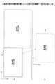
図19は、本実施形態の画像処理装置によって生成される画像データを示す図の一例である。まず、画面の設定等が図19(A)に示すような状態であるとする。すなわち、図18に示すような画面の設定であるとする。そして、判別処理が行われた後に、キャプチャが行われると、ノートPCは、図19(B)に示すような画像データDIMGを生成することができる。具体的には、図19(A)のように、第1画面と第2画面とがつながっている状態であっても、判別処理を行うと、境界SLが分かるため、ノートPCは、つながっている複数の画面のうち、第1画面を切り出して、図19(B)のように第1画面を示す画像データDIMGを生成することができる効果を奏する。 FIG. 19 is an example of a diagram showing image data generated by the image processing apparatus of the present embodiment. First, it is assumed that the screen settings and the like are as shown in FIG. 19 (A). That is, it is assumed that the screen settings are as shown in FIG. Then, when the capture is performed after the discrimination process is performed, the notebook PC can generate the image data DIMG as shown in FIG. 19 (B). Specifically, as shown in FIG. 19A, even when the first screen and the second screen are connected, the boundary SL can be found by performing the discrimination process, so that the notebook PCs are connected. Among the plurality of screens, the first screen can be cut out to generate the image data DIMG showing the first screen as shown in FIG. 19B.
一方で、判別処理が行われない場合(以下「比較例」という。)では、以下のような画像データが生成される場合が多い。 On the other hand, when the discrimination process is not performed (hereinafter referred to as "comparative example"), the following image data is often generated.
図20は、比較例において生成される画像データを示す図の一例である。なお、図20(A)は、図19(A)と同様の画面の設定であるとする。すなわち、図20(A)に示すように、まず、第1画面と第2画面は、がつながっている状態である。 FIG. 20 is an example of a diagram showing image data generated in the comparative example. It is assumed that FIG. 20 (A) has the same screen settings as those in FIG. 19 (A). That is, as shown in FIG. 20A, first, the first screen and the second screen are in a connected state.
判別処理が行われないと、ノートPCは、第1画面及び第2画面の区切りが分からない状態である。そのため、キャプチャが行われると、図20(B)に示すように、第1画面及び第2画面の両方を示す画像データが生成される場合が多い。このような場合には、ユーザは、図20(B)のような画像データに対して、画像編集ソフト等を用いて、第1画面の部分等を切り出す作業を行う必要がある。 If the discrimination process is not performed, the notebook PC is in a state where the division between the first screen and the second screen cannot be known. Therefore, when the capture is performed, as shown in FIG. 20B, image data showing both the first screen and the second screen is often generated. In such a case, the user needs to cut out a part of the first screen or the like from the image data as shown in FIG. 20B by using image editing software or the like.
一方で、判別処理が行われる構成であると、ノートPCは、第1画面の部分を切り出すことができるため、ユーザによる切り出し作業等を省略させることができる。ゆえに、ノートPCは、判別処理によって、キャプチャによる作業を効率化させることができる効果を奏する。 On the other hand, in the configuration in which the discrimination process is performed, the notebook PC can cut out the portion of the first screen, so that the user can omit the cutting work and the like. Therefore, the notebook PC has an effect that the work by capture can be made more efficient by the discrimination process.
<第2実施形態>
第2実施形態は、例えば、第1実施形態と同様の全体構成及びハードウェア構成によって実現される。以下、第1実施形態と同様の全体構成及びハードウェア構成である例で説明し、重複する説明を省略する。第2実施形態では、以下のような条件判定処理が行われる点が異なる。<Second Embodiment>
The second embodiment is realized, for example, by the same overall configuration and hardware configuration as the first embodiment. Hereinafter, an example having the same overall configuration and hardware configuration as in the first embodiment will be described, and duplicate description will be omitted. The second embodiment is different in that the following condition determination processing is performed.
<条件判定処理例>
ノートPCは、例えば、以下のような画面判定処理を行う条件判定部を備える。なお、条件判定部は、例えば、CPU101(図5)等によって実現される。<Example of condition judgment processing>
The notebook PC includes, for example, a condition determination unit that performs the following screen determination processing. The condition determination unit is realized by, for example, CPU 101 (FIG. 5).
図21は、本実施形態の画像処理装置による条件判定処理を示すフローチャートの一例である。なお、条件判定処理は、アプリケーションを起動する際又は画面に係る設定を変更する際等に行われる処理である。 FIG. 21 is an example of a flowchart showing condition determination processing by the image processing apparatus of the present embodiment. The condition determination process is a process performed when the application is started or when the setting related to the screen is changed.
ステップS21では、ノートPCは、複数の画面のうち、所定の条件を満たす画面があるか否か判断する。例えば、図2に示すように、ノートPC6が、ノートPC6が有するディスプレイと、電子黒板2が有するディスプレイとに画面を表示する例で説明する。このような場合において、電子黒板2の仕様等によって、電子黒板2が有するディスプレイに表示させる画面は、所定の条件を満たしていないと、表示できない場合等がある。 In step S21, the notebook PC determines whether or not there is a screen satisfying a predetermined condition among the plurality of screens. For example, as shown in FIG. 2, an example will be described in which the
例えば、所定の条件は、所定の解像度であるか又は所定の解像度以上の解像度の画面等である。以下、電子黒板2が有するディスプレイに表示させる画面は、「1920×1080」の解像度(以下「FHD」という。)でないと、電子黒板2が有するディスプレイに表示させることができない場合であるとする例で説明する。この例では、所定の条件が「FHDの解像度の画面である」とあらかじめノートPCにユーザによって設定される。また、以下の説明は、図11に示すように、「拡張」の設定がノートPCに設定される例で説明する。 For example, a predetermined condition is a screen having a predetermined resolution or a resolution equal to or higher than a predetermined resolution. Hereinafter, it is assumed that the screen to be displayed on the display of the
この例では、ステップS21では、ノートPCは、第1画面及び第2画面のうち、どちらか一方又は双方の解像度がFHDであるか否か判断する。なお、各画面の解像度は、ノートPCによって、図12に示すステップS06等のように取得される。例えば、図13に示す例の場合には、第2画面が「1920×1080」の解像度であるため、第2画面がFHDであると判断される。そのため、図13に示す例では、ノートPCは、ステップS21において所定の条件を満たす画面があると判断する(ステップS21でYES)。 In this example, in step S21, the notebook PC determines whether or not the resolution of either one or both of the first screen and the second screen is FHD. The resolution of each screen is acquired by the notebook PC as in step S06 shown in FIG. For example, in the case of the example shown in FIG. 13, since the second screen has a resolution of "1920 × 1080", it is determined that the second screen is FHD. Therefore, in the example shown in FIG. 13, the notebook PC determines that there is a screen satisfying a predetermined condition in step S21 (YES in step S21).
次に、複数の画面のうち、所定の条件を満たす画面があると(ステップS21でYES)、ノートPCは、ステップS22に進む。一方で、複数の画面のうち、所定の条件を満たす画面がないと(ステップS21でNO)、ノートPCは、ステップS24に進む。 Next, if there is a screen satisfying a predetermined condition among the plurality of screens (YES in step S21), the notebook PC proceeds to step S22. On the other hand, if there is no screen satisfying a predetermined condition among the plurality of screens (NO in step S21), the notebook PC proceeds to step S24.
ステップS22では、ノートPCは、画像表示装置がノートPCに接続されているか否か判断する。例えば、ノートPCは、図2に示すケーブル10が電気的に接続されているか否か等をチェックし、電子黒板2が接続されているか否かを判断する。 In step S22, the notebook PC determines whether or not the image display device is connected to the notebook PC. For example, the notebook PC checks whether or not the
この例では、ケーブル10が電気的に接続されていないと、ノートPCは、電子黒板2から各種データを受信するのが難しい。そのため、電子黒板2上に書き込みが行われても、アプリケーションにデータが送信されない場合が多い。そこで、ステップS22のようにケーブル10が電気的に接続されている状態であるか否かが判断されると、ノートPCは、電子黒板2上の書き込みがアプリケーションに反映されないのを少なくできる。 In this example, if the
次に、画像表示装置がノートPCに接続されていると(ステップS22でYES)、ノートPCは、ステップS23に進む。一方で、画像表示装置がノートPCに接続されていないと(ステップS22でNO)、ノートPCは、ステップS24に進む。 Next, if the image display device is connected to the notebook PC (YES in step S22), the notebook PC proceeds to step S23. On the other hand, if the image display device is not connected to the notebook PC (NO in step S22), the notebook PC proceeds to step S24.
なお、ステップS21及びステップS22は、図示するように、別々に行われてもよく、ステップS21の所定の条件にステップS22の判断が含まれてもよい。 As shown in the figure, steps S21 and S22 may be performed separately, and the predetermined conditions of step S21 may include the determination of step S22.
ステップS23では、ノートPCは、アプリケーション画面を所定の条件を満たす画面に表示する。例えば、図13に示す例では、第2画面が、所定の条件を満たす画面である。そこで、ステップS23では、ノートPCは、アプリケーション画面APP(図7)を第2画面に表示する。このようにすると、例えば、ノートPCは、図7の下段(「拡張」の段)のように各画面を表示することとなる。 In step S23, the notebook PC displays the application screen on a screen satisfying a predetermined condition. For example, in the example shown in FIG. 13, the second screen is a screen satisfying a predetermined condition. Therefore, in step S23, the notebook PC displays the application screen APP (FIG. 7) on the second screen. In this way, for example, the notebook PC displays each screen as shown in the lower row (“extended” row) of FIG. 7.
ステップS24では、ノートPCは、アプリケーションの起動を中止する。 In step S24, the notebook PC stops starting the application.
このような条件判定処理が行われると、ノートPCは、複数の画面のうち、所定の条件、特に解像度に係る条件を満たす画面を判定することができる。画像表示装置には、所定の条件を満たした画面でないと、画像表示装置の仕様等によって、表示できない場合がある。そのため、アプリケーション画面APP(図7)は、所定の条件を満たす画面に表示されるのが望ましい。そこで、ノートPCは、まず、所定の条件を満たす画面があるか否か判断する。そして、所定の条件を満たす画面がある場合には、ノートPCは、所定の条件を満たす画面に、アプリケーション画面APPを表示する。 When such a condition determination process is performed, the notebook PC can determine a screen that satisfies a predetermined condition, particularly a screen relating to the resolution, among a plurality of screens. The image display device may not be able to display the screen unless the screen satisfies a predetermined condition, depending on the specifications of the image display device and the like. Therefore, it is desirable that the application screen APP (FIG. 7) be displayed on a screen that satisfies a predetermined condition. Therefore, the notebook PC first determines whether or not there is a screen satisfying a predetermined condition. Then, when there is a screen satisfying a predetermined condition, the notebook PC displays the application screen APP on the screen satisfying the predetermined condition.
このように、所定の条件を満たす画面にアプリケーション画面APPが表示されると、以降、ユーザは、所定の条件を満たす画面において、アプリケーション画面APPに対して操作を行う場合が多い。そのため、画像表示装置には、アプリケーションを介して、表示することができる画面が、ノートPCによって表示される。 As described above, when the application screen APP is displayed on the screen satisfying the predetermined condition, the user often operates the application screen APP on the screen satisfying the predetermined condition thereafter. Therefore, the image display device displays a screen that can be displayed via the application by the notebook PC.
ユーザは、複数の画面のうち、どちらが所定の条件を満たす画面であるか知らない場合がある。そのため、画像表示装置を利用するのに、アプリケーション画面APPをどの画面に表示させて使用すればよいかわからない場合がある。そこで、ノートPCが所定の条件を満たす画面を判定して、アプリケーションを起動すると、ユーザは、アプリケーションを用いて画像表示装置を利用することができる。 The user may not know which of the plurality of screens satisfies a predetermined condition. Therefore, in order to use the image display device, it may not be known on which screen the application screen APP should be displayed and used. Therefore, when the notebook PC determines a screen satisfying a predetermined condition and starts the application, the user can use the image display device by using the application.
なお、「複製」の設定がノートPCに設定される場合であっても、例えば、画面が所定の解像度以上でないと、アプリケーション画面APPが画面からはみ出す場合等がある。そこで、上記の方法は、「複製」の設定がノートPCに設定される場合に行われてもよい。 Even when the "duplicate" setting is set in the notebook PC, for example, if the screen does not have a predetermined resolution or higher, the application screen APP may protrude from the screen. Therefore, the above method may be performed when the "duplicate" setting is set in the notebook PC.
<その他の実施形態>
以上、本発明を実施するための最良の形態について実施例を用いて説明したが、本発明はこうした実施例に何等限定されるものではなく、本発明の要旨を逸脱しない範囲内において種々の変形及び置換を加えることができる。<Other embodiments>
Although the best mode for carrying out the present invention has been described above with reference to examples, the present invention is not limited to these examples, and various modifications are made without departing from the gist of the present invention. And substitutions can be made.
なお、本実施形態では、電子黒板2(図2)という呼称で説明したが、電子黒板2は、電子情報ボード、電子ホワイトボード又はインタラクティブホワイトボード等のように呼ばれていてもよい。 In the present embodiment, the term "electronic blackboard 2 (FIG. 2)" has been used, but the
また、本実施形態では電子黒板2を例にして説明したが、不特定多数のものに使用され、データを作成し、該データを継続的に使用する機器に適用されてもよい。 Further, in the present embodiment, the
また、図示する構成例は、電子黒板2による処理の理解を容易にするために、主な機能に応じて分割して示した構成である。そのため、処理単位の分割の仕方又は名称によって本願発明は、限定されない。例えば、電子黒板2の処理は、処理内容に応じて更に多くの処理単位に分割してもよい。また、1つの処理単位は、更に多くの処理を含むように分割されてもよい。 Further, the illustrated configuration example is a configuration divided according to the main functions in order to facilitate understanding of the processing by the
他にも、画像表示装置及び画像処理装置は、1つの情報処理装置によって実現される構成に限られない。すなわち、画像表示装置及び画像処理装置は、2つ以上の情報処理装置を有する情報処理システムであってもよい。なお、画像表示装置又は画像処理装置では、各処理の一部又は全部が分散、冗長、並列又はこれらを組み合わせるように、処理が行われてもよい。 In addition, the image display device and the image processing device are not limited to the configuration realized by one information processing device. That is, the image display device and the image processing device may be an information processing system having two or more information processing devices. In the image display device or the image processing device, the processing may be performed so that a part or all of each processing is distributed, redundant, parallel, or a combination thereof.
なお、本発明に係る各処理の全部又は一部は、アセンブラ、C、C++、C#及びJava(登録商標)等のプログラミング言語等で記述されたコンピュータに画像処理方法を実行させるためのプログラムによって実現されてもよい。すなわち、プログラムは、画像処理装置等のコンピュータに画像処理方法を実行させるためのコンピュータプログラムである。 In addition, all or a part of each process according to the present invention is carried out by a program for causing a computer described in a programming language such as assembler, C, C ++, C # and Java (registered trademark) to execute an image processing method. It may be realized. That is, the program is a computer program for causing a computer such as an image processing apparatus to execute an image processing method.
また、プログラムは、ROM又はEEPROM(Electrically Erasable Programmable ROM)等のコンピュータが読み取り可能な記録媒体に格納して頒布することができる。さらに、記録媒体は、EPROM(Erasable Programmable ROM)、フラッシュメモリ、フレキシブルディスク、光学ディスク、SD(登録商標)カード又はMO等でもよい。さらにまた、プログラムは、電気通信回線を通じて頒布することができる。 Further, the program can be stored and distributed in a computer-readable recording medium such as ROM or EEPROM (Electrically Erasable Programmable ROM). Further, the recording medium may be an EPROM (Erasable Programmable ROM), a flash memory, a flexible disk, an optical disk, an SD (registered trademark) card, an MO, or the like. Furthermore, the program can be distributed over telecommunication lines.
1 画像処理システム
2 電子黒板
3 ディスプレイ
4 電子ペン
6 ノートPC1
Claims (6)
Translated fromJapanese前記画像処理装置のディスプレイに表示される第1画面と、前記画像処理装置のディスプレイの拡張として前記表示装置のディスプレイに表示される第2画面とを表示させる表示部と、
前記第1画面と、前記第2画面とを識別するデータを少なくとも有する識別データを前記表示装置から取得する取得部と、
前記識別データに基づいて、前記第1画面及び前記第2画面の区切りを判別する判別部と、
前記第1画面に表示されるグラフィックユーザインタフェースの第1面積と、前記第2画面に表示される前記グラフィックユーザインタフェースの第2面積とを比較し前記第1画面又は前記第2画面のいずれかを取り込んで、画像データを生成する画像処理部と、を備える
画像処理装置。An image processing device connected to a display device.
A display unit for displaying a first screen displayed on the display of the image processing device and a second screen displayed on the display of the display device as an extension of the display of the image processing device.
An acquisition unit that acquires identification data from the display device that has at least data that identifies the first screen and the second screen.
Based on the identification data, a discriminating unit that discriminates between the first screen and the second screen, and a discriminating unit.
The first area of the graphic user interface displayed on the first screen is compared with the second area of the graphic user interface displayed on the second screen, and either the first screen or the second screen is displayed. An image processing device including an image processing unit that captures images and generates image data.
前記第1画像に対する前記表示装置に入力される操作を受け付けると、前記操作によって書き込まれる書込と、前記第1画像とを一体にした第2画像を生成する請求項1に記載の画像処理装置。When the image processing unit generates the image data, the first image based on the image data is displayed on the display device.
The image processing device accordingto claim 1 , wherein when an operation input to the display device for the first image is received, the writing written by the operation and the second image in which the first image is integrated are generated. ..
前記画像処理装置のディスプレイに表示される第1画面と、前記画像処理装置のディスプレイの拡張として前記表示装置のディスプレイに表示される第2画面とを表示させる表示部と、
前記第1画面と、前記第2画面とを識別するデータを少なくとも有する識別データを前記表示装置から取得する取得部と、
前記識別データに基づいて、前記第1画面及び前記第2画面の区切りを判別する判別部と、
前記第1画面に表示されるグラフィックユーザインタフェースの第1面積と、前記第2画面に表示される前記グラフィックユーザインタフェースの第2面積とを比較し前記第1画面又は前記第2画面のいずれかを取り込んで、画像データを生成する画像処理部と、を備える
画像処理システム。An image processing system having one or more information processing devices and having an image processing device connected to the display device.
A display unit for displaying a first screen displayed on the display of the image processing device and a second screen displayed on the display of the display device as an extension of the display of the image processing device.
An acquisition unit that acquires identification data from the display device that has at least data that identifies the first screen and the second screen.
Based on the identification data, a discriminating unit that discriminates between the first screen and the second screen, and a discriminating unit.
The first area of the graphic user interface displayed on the first screen is compared with the second area of the graphic user interface displayed on the second screen, and either the first screen or the second screen is displayed. An image processing system including an image processing unit that captures images and generates image data.
前記画像処理装置が、前記画像処理装置のディスプレイに表示される第1画面と、前記画像処理装置のディスプレイの拡張として前記表示装置のディスプレイに表示される第2画面とを表示させる表示手順と、
前記画像処理装置が、前記第1画面と、前記第2画面とを識別するデータを少なくとも有する識別データを前記表示装置から取得する取得手順と、
前記画像処理装置が、前記識別データに基づいて、前記第1画面及び前記第2画面の区切りを判別する判別手順と、
前記画像処理装置が、前記第1画面に表示されるグラフィックユーザインタフェースの第1面積と、前記第2画面に表示される前記グラフィックユーザインタフェースの第2面積とを比較し前記第1画面又は前記第2画面のいずれかを取り込んで、画像データを生成する画像処理手順と
を含む画像処理方法。It is an image processing method performed by an image processing device connected to a display device.
A display procedure in which the image processing device displays a first screen displayed on the display of the image processing device and a second screen displayed on the display of the display device as an extension of the display of the image processing device.
An acquisition procedure in which the image processing device acquires identification data from the display device, which has at least data for identifying the first screen and the second screen.
A determination procedure in which the image processing device determines the division between the first screen and the second screen based on the identification data, and a determination procedure.
The image processing device compares the first area of the graphic user interface displayed on the first screen with the second area of the graphic user interface displayed on the second screen, and the first screen or the first screen. An image processing method including an image processing procedure for capturing one of two screens and generating image data.
前記コンピュータが、前記コンピュータのディスプレイに表示される第1画面と、前記コンピュータのディスプレイの拡張として前記表示装置のディスプレイに表示される第2画面とを表示させる表示手順と、
前記コンピュータが、前記第1画面と、前記第2画面とを識別するデータを少なくとも有する識別データを前記表示装置から取得する取得手順と、
前記コンピュータが、前記識別データに基づいて、前記第1画面及び前記第2画面の区切りを判別する判別手順と、
前記コンピュータが、前記第1画面に表示されるグラフィックユーザインタフェースの第1面積と、前記第2画面に表示される前記グラフィックユーザインタフェースの第2面積とを比較し前記第1画面又は前記第2画面のいずれかを取り込んで、画像データを生成する画像処理手順と
を実行させるためのプログラム。A program that causes a computer connected to a display device to execute an image processing method.
A display procedure in which the computer displays a first screen displayed on the display of the computer and a second screen displayed on the display of the display device as an extension of the display of the computer.
An acquisition procedure in which the computer acquires identification data from the display device having at least data for identifying the first screen and the second screen.
A determination procedure in which the computer determines the division between the first screen and the second screen based on the identification data, and a determination procedure.
The computer compares the first area of the graphic user interface displayed on the first screen with the second area of the graphic user interface displayed on the second screen, and the first screen or the second screen. A program for importing any of the above and executing an image processing procedure that generates image data.
Priority Applications (2)
| Application Number | Priority Date | Filing Date | Title |
|---|---|---|---|
| JP2016104554AJP6988060B2 (en) | 2016-05-25 | 2016-05-25 | Image processing equipment, image processing system, image processing method and program |
| US15/585,196US10725653B2 (en) | 2016-05-25 | 2017-05-03 | Image processing device, image processing system, and image processing method |
Applications Claiming Priority (1)
| Application Number | Priority Date | Filing Date | Title |
|---|---|---|---|
| JP2016104554AJP6988060B2 (en) | 2016-05-25 | 2016-05-25 | Image processing equipment, image processing system, image processing method and program |
Publications (2)
| Publication Number | Publication Date |
|---|---|
| JP2017211494A JP2017211494A (en) | 2017-11-30 |
| JP6988060B2true JP6988060B2 (en) | 2022-01-05 |
Family
ID=60417948
Family Applications (1)
| Application Number | Title | Priority Date | Filing Date |
|---|---|---|---|
| JP2016104554AActiveJP6988060B2 (en) | 2016-05-25 | 2016-05-25 | Image processing equipment, image processing system, image processing method and program |
Country Status (2)
| Country | Link |
|---|---|
| US (1) | US10725653B2 (en) |
| JP (1) | JP6988060B2 (en) |
Families Citing this family (7)
| Publication number | Priority date | Publication date | Assignee | Title |
|---|---|---|---|---|
| US9934431B2 (en)* | 2016-07-27 | 2018-04-03 | Konica Minolta Laboratory U.S.A., Inc. | Producing a flowchart object from an image |
| JP6946825B2 (en) | 2017-07-28 | 2021-10-06 | 株式会社リコー | Communication system, communication method, electronic device |
| JP6663415B2 (en)* | 2017-12-01 | 2020-03-11 | キヤノン株式会社 | Information processing apparatus, control method therefor, and program |
| JP2019199024A (en)* | 2018-05-16 | 2019-11-21 | 株式会社リコー | Electronic blackboard, operation guarantee judgement method, program, and display system |
| JP7490978B2 (en) | 2020-02-14 | 2024-05-28 | 株式会社リコー | Information processing system, information processing device, program, and information processing method |
| JP7593002B2 (en) | 2020-08-04 | 2024-12-03 | 株式会社リコー | COMMUNICATION SYSTEM, COMMUNICATION METHOD, AND PROGRAM |
| KR20220086896A (en)* | 2020-12-17 | 2022-06-24 | 삼성전자주식회사 | Electronic device for processing handwriting input and method for operating thereof |
Family Cites Families (35)
| Publication number | Priority date | Publication date | Assignee | Title |
|---|---|---|---|---|
| JP2000043484A (en) | 1998-07-30 | 2000-02-15 | Ricoh Co Ltd | Electronic blackboard system |
| JP2003069767A (en)* | 2001-08-27 | 2003-03-07 | Ricoh Co Ltd | Display system and display program |
| KR100757767B1 (en)* | 2002-05-01 | 2007-09-12 | 레노보 (싱가포르) 피티이. 엘티디. | Computers, Display Methods, and Programs |
| JP2004171131A (en)* | 2002-11-18 | 2004-06-17 | Toshiba Corp | Information processing device and display device switching method |
| US20050015731A1 (en)* | 2003-07-15 | 2005-01-20 | Microsoft Corporation | Handling data across different portions or regions of a desktop |
| US20060253797A1 (en)* | 2005-05-06 | 2006-11-09 | Microsoft Corporation | Presentation of user-specified display regions |
| US8516393B2 (en)* | 2006-12-18 | 2013-08-20 | Robert Pedersen, II | Apparatus, system, and method for presenting images in a multiple display environment |
| US7961157B2 (en)* | 2007-05-14 | 2011-06-14 | Christie Digital Systems Usa, Inc. | Configurable imaging system |
| JP2009146030A (en)* | 2007-12-12 | 2009-07-02 | Konica Minolta Holdings Inc | Information terminal system |
| JP4296213B2 (en)* | 2007-12-21 | 2009-07-15 | 株式会社東芝 | Information processing device |
| JP5191779B2 (en) | 2008-04-07 | 2013-05-08 | レノボ・シンガポール・プライベート・リミテッド | Multi-display computer system |
| JP5200979B2 (en)* | 2009-02-13 | 2013-06-05 | 日本電気株式会社 | Image transfer apparatus, method and program |
| JP5029679B2 (en)* | 2009-12-11 | 2012-09-19 | セイコーエプソン株式会社 | Image transfer apparatus and image transfer method |
| US8538741B2 (en)* | 2009-12-15 | 2013-09-17 | Ati Technologies Ulc | Apparatus and method for partitioning a display surface into a plurality of virtual display areas |
| US20110310070A1 (en)* | 2010-06-17 | 2011-12-22 | Henry Zeng | Image splitting in a multi-monitor system |
| US20120050314A1 (en)* | 2010-09-01 | 2012-03-01 | Panavio Technology Limited | Automatic split-screen controller |
| TW201308246A (en)* | 2011-05-16 | 2013-02-16 | Qisda Corp | Document providing system, electronic device and display panel |
| JP5700556B2 (en)* | 2011-09-12 | 2015-04-15 | レノボ・シンガポール・プライベート・リミテッド | Information processing apparatus, image display method thereof, and computer-executable program |
| US9182935B2 (en)* | 2011-09-27 | 2015-11-10 | Z124 | Secondary single screen mode activation through menu option |
| KR20130053185A (en)* | 2011-11-15 | 2013-05-23 | 삼성전자주식회사 | System and method for mutual control between electronic devices |
| EP2613555A3 (en)* | 2012-01-06 | 2014-04-30 | LG Electronics, Inc. | Mobile terminal with eye movement sensor and grip pattern sensor to control streaming of contents |
| US8826452B1 (en)* | 2012-01-18 | 2014-09-02 | Trend Micro Incorporated | Protecting computers against data loss involving screen captures |
| WO2013190695A1 (en)* | 2012-06-22 | 2013-12-27 | Necディスプレイソリューションズ株式会社 | Display device |
| JP6183003B2 (en)* | 2012-11-15 | 2017-08-23 | 株式会社リコー | Transmission system |
| WO2014136400A1 (en)* | 2013-03-05 | 2014-09-12 | Necカシオモバイルコミュニケーションズ株式会社 | Handheld terminal, image generation method, and non-transitory computer-readable medium containing program |
| JP2015026912A (en) | 2013-07-24 | 2015-02-05 | 株式会社リコー | Signal determination device, light projection device, and signal determination method |
| JP6244735B2 (en)* | 2013-08-15 | 2017-12-13 | 株式会社リコー | Information sharing apparatus and information sharing system |
| JP2015103106A (en) | 2013-11-26 | 2015-06-04 | 株式会社リコー | Communication device and communication program |
| JP6307746B2 (en) | 2014-03-18 | 2018-04-11 | 株式会社リコー | Destination management system, communication system, destination management method, and program |
| JP6429476B2 (en)* | 2014-03-26 | 2018-11-28 | キヤノン株式会社 | Image output device, image display device, and control method thereof |
| JP6504248B2 (en)* | 2015-05-08 | 2019-04-24 | 富士通クライアントコンピューティング株式会社 | Image output control method, image output control program and display device |
| JP6540367B2 (en) | 2015-08-21 | 2019-07-10 | 株式会社リコー | Display control apparatus, communication terminal, communication system, display control method, and program |
| JP2017046192A (en) | 2015-08-26 | 2017-03-02 | 株式会社リコー | Information processing device, program, and information processing method |
| US10303328B2 (en)* | 2015-09-14 | 2019-05-28 | Lg Electronics Inc. | Mobile terminal and method for controlling the same |
| JP6620494B2 (en) | 2015-09-30 | 2019-12-18 | 株式会社リコー | Communication system, information processing apparatus, communication method, program |
- 2016
- 2016-05-25JPJP2016104554Apatent/JP6988060B2/enactiveActive
- 2017
- 2017-05-03USUS15/585,196patent/US10725653B2/ennot_activeExpired - Fee Related
Also Published As
| Publication number | Publication date |
|---|---|
| US20170344248A1 (en) | 2017-11-30 |
| US10725653B2 (en) | 2020-07-28 |
| JP2017211494A (en) | 2017-11-30 |
Similar Documents
| Publication | Publication Date | Title |
|---|---|---|
| JP7042622B2 (en) | Image processing device, image processing system, image processing method, and program | |
| JP6988060B2 (en) | Image processing equipment, image processing system, image processing method and program | |
| US11209921B2 (en) | Electronic blackboard, storage medium, and information display method | |
| US20180082663A1 (en) | Information processing apparatus, image displaying method, and non-transitory computer readable medium | |
| JP2016134014A (en) | Electronic information board device, information processing method and program | |
| US10649754B2 (en) | Image processing device and electronic whiteboard | |
| JP6160305B2 (en) | Image processing apparatus, program, image processing system, and image processing method | |
| US10489049B2 (en) | Image processing apparatus, image processing system, and image processing method | |
| JP2015158900A (en) | Information processing device, information processing method and information processing program | |
| JP6540367B2 (en) | Display control apparatus, communication terminal, communication system, display control method, and program | |
| WO2017051687A1 (en) | Digital blackboard, digital blackboard image processing method, and recording medium whereupon digital blackboard program is recorded | |
| US10831338B2 (en) | Hiding regions of a shared document displayed on a screen | |
| JP6773977B2 (en) | Terminal device and operation control program | |
| JP2020154660A (en) | Display device and display method | |
| JP2014160416A (en) | Browsing system and program | |
| JP6225724B2 (en) | Information sharing system, information sharing method, information processing apparatus, and information processing method | |
| JP7383959B2 (en) | Display device, usage providing method, program, image processing system | |
| JP4998363B2 (en) | Program and information processing apparatus | |
| JP2023106170A (en) | Business card management system and business card management program | |
| JP2023106171A (en) | Business card management system and business card management program | |
| JP2020149634A (en) | Image processing equipment, methods, and programs | |
| JP2020127095A (en) | Information processing system, electronic blackboard, and program |
Legal Events
| Date | Code | Title | Description |
|---|---|---|---|
| A80 | Written request to apply exceptions to lack of novelty of invention | Free format text:JAPANESE INTERMEDIATE CODE: A80 Effective date:20160616 | |
| A621 | Written request for application examination | Free format text:JAPANESE INTERMEDIATE CODE: A621 Effective date:20190315 | |
| A977 | Report on retrieval | Free format text:JAPANESE INTERMEDIATE CODE: A971007 Effective date:20200128 | |
| A131 | Notification of reasons for refusal | Free format text:JAPANESE INTERMEDIATE CODE: A131 Effective date:20200303 | |
| A521 | Request for written amendment filed | Free format text:JAPANESE INTERMEDIATE CODE: A523 Effective date:20200410 | |
| A131 | Notification of reasons for refusal | Free format text:JAPANESE INTERMEDIATE CODE: A131 Effective date:20200804 | |
| A521 | Request for written amendment filed | Free format text:JAPANESE INTERMEDIATE CODE: A523 Effective date:20200911 | |
| A131 | Notification of reasons for refusal | Free format text:JAPANESE INTERMEDIATE CODE: A131 Effective date:20201013 | |
| A521 | Request for written amendment filed | Free format text:JAPANESE INTERMEDIATE CODE: A523 Effective date:20201204 | |
| A131 | Notification of reasons for refusal | Free format text:JAPANESE INTERMEDIATE CODE: A131 Effective date:20210601 | |
| A521 | Request for written amendment filed | Free format text:JAPANESE INTERMEDIATE CODE: A523 Effective date:20210701 | |
| TRDD | Decision of grant or rejection written | ||
| A01 | Written decision to grant a patent or to grant a registration (utility model) | Free format text:JAPANESE INTERMEDIATE CODE: A01 Effective date:20211102 | |
| A61 | First payment of annual fees (during grant procedure) | Free format text:JAPANESE INTERMEDIATE CODE: A61 Effective date:20211115 | |
| R151 | Written notification of patent or utility model registration | Ref document number:6988060 Country of ref document:JP Free format text:JAPANESE INTERMEDIATE CODE: R151 |