JP6987693B2 - Inspection method, inspection equipment, and plating equipment equipped with this - Google Patents
Inspection method, inspection equipment, and plating equipment equipped with thisDownload PDFInfo
- Publication number
- JP6987693B2 JP6987693B2JP2018086597AJP2018086597AJP6987693B2JP 6987693 B2JP6987693 B2JP 6987693B2JP 2018086597 AJP2018086597 AJP 2018086597AJP 2018086597 AJP2018086597 AJP 2018086597AJP 6987693 B2JP6987693 B2JP 6987693B2
- Authority
- JP
- Japan
- Prior art keywords
- liquid
- substrate
- area
- substrate holder
- image data
- Prior art date
- Legal status (The legal status is an assumption and is not a legal conclusion. Google has not performed a legal analysis and makes no representation as to the accuracy of the status listed.)
- Active
Links
- 238000007747platingMethods0.000titleclaimsdescription74
- 238000007689inspectionMethods0.000titleclaimsdescription56
- 238000000034methodMethods0.000titleclaimsdescription37
- 239000000758substrateSubstances0.000claimsdescription191
- 239000007788liquidSubstances0.000claimsdescription106
- 238000007789sealingMethods0.000claimsdescription32
- 238000001514detection methodMethods0.000claimsdescription20
- 239000003086colorantSubstances0.000claimsdescription5
- 208000033748Device issuesDiseases0.000claims1
- 238000012360testing methodMethods0.000claims1
- 238000004140cleaningMethods0.000description24
- 230000002265preventionEffects0.000description14
- 230000005856abnormalityEffects0.000description7
- 230000002093peripheral effectEffects0.000description7
- 230000032258transportEffects0.000description5
- 238000010586diagramMethods0.000description3
- NJPPVKZQTLUDBO-UHFFFAOYSA-NnovaluronChemical compoundC1=C(Cl)C(OC(F)(F)C(OC(F)(F)F)F)=CC=C1NC(=O)NC(=O)C1=C(F)C=CC=C1FNJPPVKZQTLUDBO-UHFFFAOYSA-N0.000description3
- 238000013473artificial intelligenceMethods0.000description2
- 238000009713electroplatingMethods0.000description2
- 238000005406washingMethods0.000description2
- XLYOFNOQVPJJNP-UHFFFAOYSA-NwaterSubstancesOXLYOFNOQVPJJNP-UHFFFAOYSA-N0.000description2
- RYGMFSIKBFXOCR-UHFFFAOYSA-NCopperChemical compound[Cu]RYGMFSIKBFXOCR-UHFFFAOYSA-N0.000description1
- BZHJMEDXRYGGRV-UHFFFAOYSA-NVinyl chlorideChemical compoundClC=CBZHJMEDXRYGGRV-UHFFFAOYSA-N0.000description1
- 238000007664blowingMethods0.000description1
- 229910052802copperInorganic materials0.000description1
- 239000010949copperSubstances0.000description1
- 230000000694effectsEffects0.000description1
- 238000005530etchingMethods0.000description1
- 230000005484gravityEffects0.000description1
- 230000008595infiltrationEffects0.000description1
- 238000001764infiltrationMethods0.000description1
- 230000035515penetrationEffects0.000description1
- 239000004065semiconductorSubstances0.000description1
- 238000002791soakingMethods0.000description1
- 125000006850spacer groupChemical group0.000description1
- 235000012431wafersNutrition0.000description1
Images


Classifications
- C—CHEMISTRY; METALLURGY
- C25—ELECTROLYTIC OR ELECTROPHORETIC PROCESSES; APPARATUS THEREFOR
- C25D—PROCESSES FOR THE ELECTROLYTIC OR ELECTROPHORETIC PRODUCTION OF COATINGS; ELECTROFORMING; APPARATUS THEREFOR
- C25D17/00—Constructional parts, or assemblies thereof, of cells for electrolytic coating
- C25D17/001—Apparatus specially adapted for electrolytic coating of wafers, e.g. semiconductors or solar cells
- C—CHEMISTRY; METALLURGY
- C25—ELECTROLYTIC OR ELECTROPHORETIC PROCESSES; APPARATUS THEREFOR
- C25D—PROCESSES FOR THE ELECTROLYTIC OR ELECTROPHORETIC PRODUCTION OF COATINGS; ELECTROFORMING; APPARATUS THEREFOR
- C25D21/00—Processes for servicing or operating cells for electrolytic coating
- C—CHEMISTRY; METALLURGY
- C25—ELECTROLYTIC OR ELECTROPHORETIC PROCESSES; APPARATUS THEREFOR
- C25D—PROCESSES FOR THE ELECTROLYTIC OR ELECTROPHORETIC PRODUCTION OF COATINGS; ELECTROFORMING; APPARATUS THEREFOR
- C25D17/00—Constructional parts, or assemblies thereof, of cells for electrolytic coating
- C25D17/004—Sealing devices
- C—CHEMISTRY; METALLURGY
- C25—ELECTROLYTIC OR ELECTROPHORETIC PROCESSES; APPARATUS THEREFOR
- C25D—PROCESSES FOR THE ELECTROLYTIC OR ELECTROPHORETIC PRODUCTION OF COATINGS; ELECTROFORMING; APPARATUS THEREFOR
- C25D17/00—Constructional parts, or assemblies thereof, of cells for electrolytic coating
- C25D17/005—Contacting devices
- C—CHEMISTRY; METALLURGY
- C25—ELECTROLYTIC OR ELECTROPHORETIC PROCESSES; APPARATUS THEREFOR
- C25D—PROCESSES FOR THE ELECTROLYTIC OR ELECTROPHORETIC PRODUCTION OF COATINGS; ELECTROFORMING; APPARATUS THEREFOR
- C25D17/00—Constructional parts, or assemblies thereof, of cells for electrolytic coating
- C25D17/06—Suspending or supporting devices for articles to be coated
- C—CHEMISTRY; METALLURGY
- C25—ELECTROLYTIC OR ELECTROPHORETIC PROCESSES; APPARATUS THEREFOR
- C25D—PROCESSES FOR THE ELECTROLYTIC OR ELECTROPHORETIC PRODUCTION OF COATINGS; ELECTROFORMING; APPARATUS THEREFOR
- C25D21/00—Processes for servicing or operating cells for electrolytic coating
- C25D21/12—Process control or regulation
- C—CHEMISTRY; METALLURGY
- C25—ELECTROLYTIC OR ELECTROPHORETIC PROCESSES; APPARATUS THEREFOR
- C25D—PROCESSES FOR THE ELECTROLYTIC OR ELECTROPHORETIC PRODUCTION OF COATINGS; ELECTROFORMING; APPARATUS THEREFOR
- C25D7/00—Electroplating characterised by the article coated
- C25D7/12—Semiconductors
- G—PHYSICS
- G01—MEASURING; TESTING
- G01N—INVESTIGATING OR ANALYSING MATERIALS BY DETERMINING THEIR CHEMICAL OR PHYSICAL PROPERTIES
- G01N21/00—Investigating or analysing materials by the use of optical means, i.e. using sub-millimetre waves, infrared, visible or ultraviolet light
- G01N21/84—Systems specially adapted for particular applications
- G01N21/88—Investigating the presence of flaws or contamination
- G01N21/94—Investigating contamination, e.g. dust
- G01N2021/945—Liquid or solid deposits of macroscopic size on surfaces, e.g. drops, films, or clustered contaminants
Landscapes
- Chemical & Material Sciences (AREA)
- Engineering & Computer Science (AREA)
- Chemical Kinetics & Catalysis (AREA)
- Electrochemistry (AREA)
- Materials Engineering (AREA)
- Metallurgy (AREA)
- Organic Chemistry (AREA)
- Life Sciences & Earth Sciences (AREA)
- Sustainable Development (AREA)
- Automation & Control Theory (AREA)
- Physics & Mathematics (AREA)
- Health & Medical Sciences (AREA)
- Analytical Chemistry (AREA)
- Biochemistry (AREA)
- General Health & Medical Sciences (AREA)
- General Physics & Mathematics (AREA)
- Immunology (AREA)
- Pathology (AREA)
- Electroplating Methods And Accessories (AREA)
- Chemically Coating (AREA)
Description
Translated fromJapanese本発明は、検査方法、検査装置、及びこれを備えためっき装置に関する。 The present invention relates to an inspection method, an inspection apparatus, and a plating apparatus including the inspection method.
従来、めっき液を収納しためっき槽に、基板ホルダに保持された基板を鉛直方向に差し込んで電解めっきを行う装置が知られている(例えば、特許文献1参照)。また、基板ホルダに保持された基板を水平方向にして電解めっきを行う装置も知られている(例えば、特許文献2参照)。このようなめっき装置で使用される基板ホルダは、基板の表面をシールして、めっき液が入り込まない空間を形成する。基板ホルダは、この空間内において、基板の表面と接触して基板に電流を流すための電気接点を有する。 Conventionally, there is known an apparatus for performing electrolytic plating by vertically inserting a substrate held in a substrate holder into a plating tank containing a plating solution (see, for example, Patent Document 1). Further, there is also known an apparatus for performing electrolytic plating with the substrate held in the substrate holder in the horizontal direction (see, for example, Patent Document 2). The substrate holder used in such a plating apparatus seals the surface of the substrate to form a space in which the plating solution does not enter. The substrate holder has electrical contacts in this space for contacting the surface of the substrate and allowing current to flow through the substrate.
このような基板ホルダは、めっき処理には非常に重要な役割を果たしている。具体的には、基板ホルダの電気接点が適切に基板の表面に接触することにより、適切な電流が基板に流れ、均一なめっき膜を基板に形成することができる。また、基板ホルダが基板の表面を適切にシールすることにより、上記空間にめっき液が入り込むことを防止している。これにより、電気接点がめっき液と接触して、電気接点が腐食すること及び基板に流れる電流が局所的に変化すること等を抑制している。言い換えれば、例えば、電気接点に破損や腐食が生じた場合、適切に基板に電流を流すことができない。また、上記空間にめっき液が入り込むと、めっき液が存在する部分とそれ以外の部分とで基板に流れる電流が異なり、基板に形成されるめっき膜の均一性が低下する。例えば、基板ホルダのシール部に異常が生じた場合に、めっき液が上記空間に入り込んでしまう。このため、基板ホルダに異常が生じているか否かを検査することは、適切なめっき処理を継続するために重要な作業である。 Such a substrate holder plays a very important role in the plating process. Specifically, when the electrical contacts of the substrate holder appropriately contact the surface of the substrate, an appropriate current flows through the substrate, and a uniform plating film can be formed on the substrate. Further, the substrate holder appropriately seals the surface of the substrate to prevent the plating solution from entering the space. As a result, the electric contacts come into contact with the plating solution to prevent the electric contacts from corroding and the current flowing through the substrate from locally changing. In other words, for example, if the electrical contacts are damaged or corroded, it is not possible to properly pass a current through the substrate. Further, when the plating solution enters the space, the current flowing through the substrate differs between the portion where the plating solution exists and the portion other than the present portion, and the uniformity of the plating film formed on the substrate is lowered. For example, if an abnormality occurs in the sealing portion of the substrate holder, the plating solution will enter the space. Therefore, inspecting whether or not an abnormality has occurred in the substrate holder is an important task for continuing an appropriate plating process.
基板ホルダの上記空間にめっき液や洗浄液等の液体が入り込んだか否かは、めっき後の基板ホルダから基板を取り外すときに確認されていた。具体的には、基板ホルダを開閉する装置において基板ホルダを開いたときに液体が上記空間から流出し、この液体をドレンパンで捕集し、ドレンパンの下流に設けられた液体センサでその液体を検知する。 Whether or not a liquid such as a plating solution or a cleaning solution entered the space of the substrate holder was confirmed when the substrate was removed from the substrate holder after plating. Specifically, when the substrate holder is opened in the device for opening and closing the substrate holder, the liquid flows out from the above space, the liquid is collected by the drain pan, and the liquid is detected by the liquid sensor provided downstream of the drain pan. do.
しかしながら、このような構成で液体を検知する場合、少量の液体は検知され難いという問題がある。具体的には、液体が少量である場合、液体がドレンパンを下流側に向かって流れても、液体センサまで到達しないことがあり得る。この場合、液体が上記空間に浸入しているにも関わらず、基板ホルダに異常が生じていることが検知できないことになる。 However, when a liquid is detected with such a configuration, there is a problem that it is difficult to detect a small amount of liquid. Specifically, when the amount of liquid is small, even if the liquid flows downstream through the drain pan, it may not reach the liquid sensor. In this case, it cannot be detected that an abnormality has occurred in the substrate holder even though the liquid has penetrated into the space.
本発明は上記問題に鑑みてなされたものであり、その目的の一つは、少量の液体であっても検知することができる基板ホルダの検査装置を提供することである。 The present invention has been made in view of the above problems, and one of the objects thereof is to provide a substrate holder inspection device capable of detecting even a small amount of liquid.
本発明の一形態によれば、基板を挟み込んで保持する第1部材及び第2部材と、前記基
板の被処理面と接触するように構成される電気接点と、液体が前記電気接点と接触しないように前記基板の前記被処理面と接触するシール部材と、を有し、前記第1部材が前記シール部材により前記液体の浸入が防止された表面領域を有し、前記第2部材が前記シール部材を有する、基板ホルダの検査方法が提供される。この検査方法は、基板ホルダ開閉装置の保持部によって前記第2部材を保持して、前記第1部材から前記第2部材を取り外す工程と、前記第1部材と前記第2部材の上方に位置する検知装置によって、前記第1部材の前記表面領域に液体が付着していることを検知する検知工程と、を有する。According to one embodiment of the present invention, the first member and the second member that sandwich and hold the substrate, the electric contacts configured to come into contact with the surface to be processed of the substrate, and the liquid do not come into contact with the electric contacts. As described above, the first member has a surface region in which the liquid is prevented from entering by the sealing member, and the second member has the sealing member, which has a sealing member in contact with the surface to be processed of the substrate. A method for inspecting a substrate holder having a member is provided. This inspection method includes a step of holding the second member by a holding portion of the substrate holder opening / closing device and removing the second member from the first member, and a step of removing the second member from the first member and above the first member and the second member. It has a detection step of detecting that a liquid is attached to the surface region of the first member by a detection device.
本発明の他の一形態によれば、基板を挟み込んで保持する第1部材及び第2部材と、前記基板の被処理面と接触するように構成される電気接点と、液体が前記電気接点と接触しないように前記基板の前記被処理面と接触するシール部材と、前記シール部材により前記液体の浸入が防止された表面領域と、を有し、前記第2部材が前記シール部材を有する、基板ホルダの検査装置が提供される。この検査装置は、前記第2部材を保持する保持部を備え、前記第1部材と前記第2部材とを互いに接触又は離間させるように構成される基板ホルダ開閉装置と、前記第1部材と前記第2部材の上方に位置し、前記第1部材と前記第2部材とが互いに離間したときに前記表面領域に液体が付着していることを検知する検知装置と、を有する。 According to another embodiment of the present invention, the first member and the second member that sandwich and hold the substrate, the electric contact configured to be in contact with the surface to be processed of the substrate, and the liquid are the electric contact. A substrate having a seal member that comes into contact with the surface to be processed of the substrate so as not to come into contact with the substrate, and a surface region in which the liquid is prevented from entering by the seal member, and the second member has the seal member. A holder inspection device is provided. This inspection device includes a holding portion for holding the second member, a substrate holder opening / closing device configured to bring the first member and the second member into contact with each other or separated from each other, and the first member and the above. It has a detection device located above the second member and detecting that a liquid is attached to the surface region when the first member and the second member are separated from each other.
本発明の他の一形態によれば、上記検査装置と、前記基板ホルダに保持された基板にめっきするめっき槽と、を有する、めっき装置が提供される。 According to another embodiment of the present invention, there is provided a plating apparatus including the inspection apparatus and a plating tank for plating a substrate held in the substrate holder.
以下、本発明の実施形態について図面を参照して説明する。以下で説明する図面において、同一の又は相当する構成要素には、同一の符号を付して重複した説明を省略する。図1は、本実施形態に係るめっき装置の全体配置図である。図1に示すように、このめっき装置は、基板ホルダ60に基板をロードし、又は基板ホルダ60から基板をアンロードするロード/アンロード部170Aと、基板を処理する処理部170Bとに大きく分けられる。
Hereinafter, embodiments of the present invention will be described with reference to the drawings. In the drawings described below, the same or corresponding components are designated by the same reference numerals and duplicated description will be omitted. FIG. 1 is an overall layout of the plating apparatus according to the present embodiment. As shown in FIG. 1, this plating apparatus is roughly divided into a load /
ロード/アンロード部170Aには、3台のフープ(Front−Opening Unified Pod:FOUP)102と、アライナ30と、スピンリンスドライヤ20と、が設けられる。フープ102は、半導体ウェハ等の複数の基板を多段に収納する。アライナ30は、基板のオリフラ(オリエンテーションフラット)やノッチなどの位置を所定の方向に合わせる。スピンリンスドライヤ20は、めっき処理後の基板を高速回転させて乾燥させる。スピンリンスドライヤ20の近くには、基板ホルダ60を載置して基板の着脱を行うフィキシングユニット40(基板ホルダ開閉装置の一例に相当する)が設けられている。これらのユニット102,30,20,40の中央には、これらのユニット
間で基板を搬送する搬送用ロボットからなる基板搬送装置122が配置されている。The load /
フィキシングユニット40は、2個の基板ホルダ60を載置可能に構成される。フィキシングユニット40においては、一方の基板ホルダ60と基板搬送装置122との間で基板の受渡しが行われた後、他方の基板ホルダ60と基板搬送装置122との間で基板の受渡しが行われる。本実施形態において、フィキシングユニット40は、後述するように基板ホルダ60を検査する検査装置の機能を有する。 The
めっき装置の処理部170Bは、ストッカ124と、プリウェット槽126と、プリソーク槽128と、第1洗浄槽130aと、ブロー槽132と、第2洗浄槽130bと、めっき槽10と、を有する。ストッカ124では、基板ホルダ60の保管及び一時仮置きが行われる。プリウェット槽126では、基板が純水に浸漬される。プリソーク槽128では、基板の表面に形成したシード層等の導電層の表面にある酸化膜がエッチング除去される。第1洗浄槽130aでは、プリソーク後の基板が基板ホルダ60と共に洗浄液(純水等)で洗浄される。ブロー槽132では、洗浄後の基板の液切りが行われる。第2洗浄槽130bでは、めっき後の基板が基板ホルダ60と共に洗浄液で洗浄される。ストッカ124、プリウェット槽126、プリソーク槽128、第1洗浄槽130a、ブロー槽132、第2洗浄槽130b、及びめっき槽10は、この順に配置されている。 The processing unit 170B of the plating apparatus includes a
めっき槽10は、例えば、オーバーフロー槽を備えた複数のめっきセル134を有する。各めっきセル134は、基板を保持した基板ホルダ60を、鉛直方向を向いた姿勢で収納し、めっき液中に基板を浸漬させる。めっきセル134において基板とアノードとの間に電圧を印加することにより、基板表面に銅めっき等のめっきが行われる。 The
めっき装置は、これらの各機器の側方に位置して、これらの各機器の間で基板ホルダ60を基板とともに搬送する、例えばリニアモータ方式を採用した基板ホルダ搬送装置140を有する。この基板ホルダ搬送装置140は、第1トランスポータ142と、第2トランスポータ144を有している。第1トランスポータ142は、フィキシングユニット40、ストッカ124、プリウェット槽126、プリソーク槽128、第1洗浄槽130a、及びブロー槽132との間で基板を搬送するように構成される。第2トランスポータ144は、第1洗浄槽130a、第2洗浄槽130b、ブロー槽132、及びめっき槽10との間で基板を搬送するように構成される。具体的には、第1トランスポータ142及び第2トランスポータ144は、保持された基板の面内方向が鉛直方向を向いた状態で、基板ホルダ60を搬送する。言い換えれば、第1トランスポータ142及び第2トランスポータ144は、基板を保持した基板ホルダ60を、鉛直方向を向いた状態で搬送する。
The plating apparatus has a substrate
他の実施形態では、めっき装置は、第1トランスポータ142及び第2トランスポータ144のいずれか一方のみを備えるようにし、いずれかのトランスポータが、フィキシングユニット40、ストッカ124、プリウェット槽126、プリソーク槽128、第1洗浄槽130a、第2洗浄槽130b、ブロー槽132、及びめっき槽10の間で基板を搬送するようにしてもよい。 In another embodiment, the plating apparatus is provided with only one of the
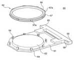
次に、図1に示した基板ホルダ60及びフィキシングユニット40について詳細に説明する。図2は、基板ホルダ60の分解斜視図である。図2に示すように基板ホルダ60は、例えば塩化ビニル製で矩形平板状の第1保持部材61(第1部材の一例に相当する)と、この第1保持部材61に対して着脱自在に構成される第2保持部材62(第2部材の一例に相当する)とを有している。基板ホルダ60の第1保持部材61の略中央部には、基板Wfを載置するための載置面63が設けられている。また、第1保持部材61の載置面63の外側には、載置面63の周囲に沿って、内方に突出する突出部を有する逆L字状のクランパ64が等間隔に複数設けられている。 Next, the
基板ホルダ60の第1保持部材61の端部には、基板ホルダ60を搬送したり吊下げ支持したりする際の支持部となる一対の略T字状のハンド65が連結されている。図1に示したストッカ124内において、ストッカ124の周壁上面にハンド65を引っ掛けることで、基板ホルダ60が垂直に吊下げ支持される。また、この吊下げ支持された基板ホルダ60のハンド65を基板ホルダ搬送装置140で把持して基板ホルダ60が搬送される。 A pair of substantially T-shaped
また、ハンド65の一つには、外部電源と電気的に接続される外部接点部68が設けられている。この外部接点部68は、複数の配線を介して載置面63の外周に設けられた複数の中継接点部(図3参照)と電気的に接続されている。 Further, one of the
第2保持部材62は、リング状のシールホルダ66を備えている。第2保持部材62のシールホルダ66には、シールホルダ66を第1保持部材61に押し付けて固定するための押えリング67が回転自在に装着されている。第2保持部材62が第1保持部材61に取り付けられることで、基板Wfが第1保持部材61と第2保持部材62とにより挟み込まれて保持される。押えリング67は、その外周部において外方に突出する複数の突条部67aを有している。突条部67aの上面とクランパ64の内方突出部の下面は、回転方向に沿って互いに逆方向に傾斜するテーパ面を有する。 The second holding
基板を保持するときは、まず、第2保持部材62を第1保持部材61から取り外した状態で、第1保持部材61の載置面63に基板Wfを載置し、第2保持部材62を取り付ける。続いて、押えリング67を時計回りに回転させて、押えリング67の突条部67aをクランパ64の内方突出部の内部(下側)に滑り込ませる。これにより、押えリング67とクランパ64にそれぞれ設けられたテーパ面を介して、第1保持部材61と第2保持部材62とが互いに締付けられてロックされ、基板Wfが保持される。基板Wfの保持を解除するときは、第1保持部材61と第2保持部材62とがロックされた状態において、押えリング67を反時計回りに回転させる。これにより、押えリング67の突条部67aが逆L字状のクランパ64から外されて、基板Wfの保持が解除される。 When holding the substrate, first, the substrate Wf is placed on the mounting
図3は、基板ホルダ60の拡大部分断面図である。図3に示すように、第2保持部材62は、基板側シール部材69(シール部材の一例に相当する)と、基板側シール部材69をシールホルダ66に固定する第1固定リング70aとを有する。第1固定リング70aは、シールホルダ66にねじ等の締結具71aを介して取付けられる。また、第2保持部材62は、ホルダ側シール部材72と、ホルダ側シール部材72をシールホルダ66に固定する第2固定リング70bとを有する。第2固定リング70bは、ねじ等の締結具71bを介してシールホルダ66に取付けられる。 FIG. 3 is an enlarged partial cross-sectional view of the
シールホルダ66の外周部には段部が設けられており、この段部には押えリング67がスペーサ73を介して回転自在に装着されている。押えリング67は、第1固定リング70aの外周部によって脱出不能に装着されている。 A step portion is provided on the outer peripheral portion of the
図3に示すように、第2保持部材62は、基板Wfの被処理面の周縁部と接触して、基板Wfに電流を流すための電気接点74を有する。電気接点74は、シールホルダ66の内周に沿って複数設けられる。また、第1保持部材61は、第2保持部材62を第1保持部材61に取り付けた状態において電気接点74と接触して、外部電源からの電流を電気接点74に供給する中継接点部79を有する。中継接点部79は、載置面63の周囲に沿って複数設けられる。中継接点部79は、外部接点部68と導通しており、これにより、外部電源から供給された電流が、外部接点部68、中継接点部79、及び電気接点74を介して、基板Wfの表面に供給される。 As shown in FIG. 3, the second holding
第2保持部材62を第1保持部材61にロックすると、基板側シール部材69は基板Wfの表面外周部に圧接される。基板側シール部材69は均一に基板Wfに押圧され、これによって基板Wfの表面外周部と第2保持部材62との隙間をシールし、めっき液又は洗浄液が電気接点74に接触することを防止する。同様に、第2保持部材62を第1保持部材61にロックすると、ホルダ側シール部材72は第1保持部材61の表面に圧接される。ホルダ側シール部材72は均一に第1保持部材61に押圧され、これによって第1保持部材61と第2保持部材62との隙間をシールし、めっき液又は洗浄液が電気接点74に接触することを防止する。 When the second holding
図3に示すように、基板側シール部材69とホルダ側シール部材72によって、第1保持部材61と第2保持部材62との間にめっき液又は洗浄液が浸入することが防止された空間(以下、本明細書において浸入防止空間という)が形成される。また、基板側シール部材69とホルダ側シール部材72によって、第1保持部材61には、めっき液又は洗浄液が浸入することが防止された表面領域が形成される。このめっき液又は洗浄液が浸入することが防止された表面領域とは、浸入防止空間を画定する第1保持部材61の任意の表面領域、例えば図3に示す表面75をいう。表面75は、載置面63の周囲に位置する。言い換えれば、当該表面領域は、基板ホルダ60に保持された基板Wfの周囲に沿って配置される。また、基板Wfの載置面63は、略円板状の台座63aの上面に位置している。表面75は、載置面63よりも低い位置に設けられる。なお、本実施形態では、基板ホルダ60は鉛直方向を向いた状態でめっき槽10に収納され、第2保持部材62全体がめっき液又は洗浄液に浸漬されるので、浸入防止空間を画定するために基板側シール部材69とホルダ側シール部材72とが必要になる。しかしながら、後述するように、水平状態の基板にめっきをするいわゆるカップ式のめっき装置で用いられる基板ホルダ60(図8参照)のように、第2保持部材62の一部だけがめっき液又は洗浄液に浸漬される場合は、基板側シール部材69のみで浸入防止空間を画定することができる。 As shown in FIG. 3, a space in which the plating solution or the cleaning liquid is prevented from entering between the first holding
次に、図2に示したフィキシングユニット40の構成について説明する。図4は、フィキシングユニット40の概略側面図である。図5は、フィキシングユニット40の部分拡大斜視図である。フィキシングユニット40は、基板ホルダ60を開閉するための装置である。言い換えれば、フィキシングユニット40は、第1保持部材61と第2保持部材62とを、互いに接触又は離間させるように構成される。フィキシングユニット40は、第1保持部材61を載置する台座41と、フレーム42と、第2保持部材62を保持して第1保持部材61から着脱する保持プレート43と、保持プレート43を鉛直方向に移動させるアクチュエータ44と、を有する。アクチュエータ44は、フレーム42に固定され、保持プレート43を鉛直方向に移動させるだけでなく、周方向に回転させる。 Next, the configuration of the fixing
図1に示した基板ホルダ搬送装置140によりフィキシングユニット40に搬送された基板ホルダ60は、保持された基板の面内方向が水平方向を向くように、台座41に水平に載置される。アクチュエータ44は、保持プレート43を下降させ、保持プレート43は第2保持部材62を保持する。アクチュエータ44は、第2保持部材62を保持した保持プレート43を周方向に回転させて、第2保持部材62と第1保持部材61とのロックを解除する。その後、アクチュエータ44は、図4及び図5に示すように、第2保持部材62を取り外した状態で保持プレート43を維持する。 The
図3に示した基板ホルダ60の基板側シール部材69又はホルダ側シール部材72が破損していたり、これらに汚れが付着していたりする場合、又は基板ホルダ60自体に歪みが生じている場合がある。このように、基板ホルダ60に異常が生じていた場合、図2及び図2に関連して説明した浸入防止空間にめっき液又は洗浄液等の液体が浸入する虞がある。したがって、浸入防止空間に液体が浸入している場合は、図4及び図5に示すように
第1保持部材61から第2保持部材62を取り外したとき、第1保持部材61の、液体の浸入が防止された表面領域、例えば図3に示した表面75に液体が付着している。The board-
本実施形態では、第1保持部材61の上記表面領域に液体が付着しているか否かを検知するための検知装置を備えている。具体的には、本実施形態では、この検知装置は、第1保持部材61の上記表面領域のうちの所定の領域の画像データを取得するように構成された画像センサ80を有する。画像センサ80は、例えば、図4及び図5に示すように、保持プレート43に取り付けられ、保持プレート43の下方に位置する第1保持部材61を撮影するように構成される。これに限らず、画像センサ80は、第1保持部材61の上記表面領域を撮影することができる任意の位置に設けることができる。画像センサ80は、図4及び図5に示すように、第1保持部材61と第2保持部材62の上方に位置することが望ましい。この場合、画像センサ80は、第1保持部材61だけでなく、第2保持部材62も撮影することができる。これにより、第2保持部材62の任意の場所に液体が付着しているか否かも検知することができる。 In the present embodiment, a detection device for detecting whether or not a liquid is attached to the surface region of the first holding
また、本実施形態では、基板ホルダ60は、図1に示した基板ホルダ搬送装置140により、鉛直方向を向いた状態でフィキシングユニット40に搬送される。このため、浸入防止空間に浸入した液体は、基板ホルダ60が搬送されている間に重力により鉛直方向最下部に向かって移動し、浸入防止空間の最下部に溜まる。そこで、本実施形態では、画像センサ80は、第1保持部材61の上記表面領域のうち、基板ホルダ60が鉛直方向を向いた状態において鉛直方向最下部を含む領域R1(図5参照)の画像データを取得するように構成される。これにより、任意の場所から液体が浸入防止空間に浸入しても、単一の画像センサ80で浸入防止空間の最下部の画像データのみを取得することで、液体の浸入を検知することができる。なお、これに限らず、基板ホルダ60が水平方向を向いた状態でフィキシングユニット40に搬送される場合等では、画像センサ80は上記表面領域の任意の領域を撮影するように構成されていてもよい。複数の画像センサ80で複数の領域を撮影してもよいし、単一の画像センサ80を移動させながら複数の領域を撮影してもよい。 Further, in the present embodiment, the
図4に示すように、フィキシングユニット40は、画像センサ80と通信可能に接続された制御装置82を備えている。制御装置82は、例えば、所定のプログラム等を格納したコンピュータ読み取り可能な記録媒体と、記録媒体のプログラムを実行するCPU(Central Processing Unit)等を有し、画像センサ80の動作を制御可能に構成される。制御装置82は、液体が付着していないときの領域R1の画像データを予め記録媒体に記録している。 As shown in FIG. 4, the fixing
次に、フィキシングユニット40における基板ホルダ60の検査方法について説明する。図6は、フィキシングユニット40における基板ホルダ60の検査方法を示すフロー図である。まず、フィキシングユニット40の保持プレート43が第2保持部材62を第1保持部材61から取り外した直後、制御装置82が開始トリガーを受けることにより(ステップS601)、画像センサ80のビジー出力をオンする(ステップS602)。なお、ここでの開始トリガーは、例えば、基板搬送装置122の移動又はフィキシングユニット40の保持プレート43の駆動等、めっき装置を構成する任意の部分の駆動であり得る。 Next, an inspection method of the
続いて、画像センサ80は、制御装置82からの指示により、第1保持部材61の領域R1の画像データを取得する(ステップS603)。取得された領域R1の画像データは制御装置82に送信される。上述したように、制御装置82は、液体が付着していないときの領域R1の画像データを予め記録媒体に記録している。そこで、制御装置82は、液体が付着していないときの領域R1と、画像センサ80が取得した領域R1の画像データ
を比較する。より具体的には、制御装置82は、液体が付着していないときの領域R1の色(例えば、グレースケール画像における数値)と、画像センサ80が取得した領域R1の画像データの色(例えば、グレースケール画像における数値)とを比較するように構成される。Subsequently, the
図7Aは、液体が付着していないときの領域R1の画像データの一例を示す図である。図7Bは、画像センサ80が取得した領域R1の画像データの一例を示す図である。図7Aに示すように、液体が付着していないときの領域R1は、第1保持部材61の色が一様に表示され得る。一方で、図7Bに示すように、画像センサ80が取得した領域R1には、めっき液又は洗浄液の液滴d1が表示されている。このため、図7Bに示す領域R1は、液滴d1が存在する部分の色が、液滴d1自身の色又は液滴d1を通過する光の屈折により、第1保持部材61の他の部分の色と異なる。制御装置82は、図7Aに示す画像データと、図7Bに示す画像データとを比較して、図7Bの領域R1の、図7Aの領域R1の色と異なる色の面積を算出する。即ち、制御装置82は、液滴d1が存在することが推定される面積を算出する。続いて、制御装置82は、算出した面積が所定値以上であるか否かを判定する(ステップS604)。なお、ここでの所定値は、制御装置82の記録装置に予め設定されており、所定値が小さいほど少量の液体を検知することができる。 FIG. 7A is a diagram showing an example of image data of the region R1 when no liquid is attached. FIG. 7B is a diagram showing an example of image data of the region R1 acquired by the
算出した面積が所定値以上であると判定された場合(ステップS604,Yes)、制御装置82は、第1保持部材61の領域R1に液滴が付着していると判定し、めっき装置に停止信号を送信することができる(ステップS605)。若しくは、制御装置82は、停止信号を送信することに代えて、又はこれと共に、図示しない報知装置により、音、光、又は振動等の警報を発生させてもよい(ステップS605)。これにより、基板ホルダ60に異常が生じたことをめっき装置の管理者に報知することができる。また、これらに代えて、又はこれらと共に、検査対象とされた基板ホルダ60を自動的にストッカ124に収納し、以後の新たな基板のめっき処理に使用しない(異常が生じた基板ホルダ60の使用を停止する)ように、基板ホルダ搬送装置140を制御してもよい。 When it is determined that the calculated area is equal to or larger than a predetermined value (step S604, Yes), the
一方で、算出した面積が所定値未満であると判定された場合(ステップS604,No)、制御装置82は、領域R1の画像データを所定回数取得したか否かを判定する(ステップS606)。本実施形態では一例として、制御装置82は、領域R1の画像データを5回取得したか否かを判定する。 On the other hand, when it is determined that the calculated area is less than a predetermined value (step S604, No), the
制御装置82が領域R1の画像データを5回取得していないと判定したときは(ステップS606,No)、ステップS603に戻り、画像センサ80は再び領域R1の画像データを取得する(ステップS603)。制御装置82が領域R1の画像データを5回取得したと判定したときは(ステップS606)、めっき装置の運転が継続される。つまり、この場合は、所定の回数取得した領域R1の画像データの全てにおいて、算出された面積が所定値未満であったということになり、基板ホルダ60に異常が生じていないものと判断される。ステップS606における画像データの取得回数は、1又は複数の数値を予め制御装置82に設定することができる。この設定回数が複数である場合、設定回数が1である場合に比べて液滴d1の誤検知の可能性を低減することができる。 When the
なお、例えば4回目に取得された領域R1の画像データについて、算出した面積が所定値以上であると判定された場合(ステップS604,Yes)、ステップS605に進むことになる。即ち、画像データの取得回数として設定された回数が5であったとしても、5回目の画像データの取得は行われず、4回目の画像データの取得が最後となる。したがって、制御装置82は、画像データの取得回数として複数が設定されていた場合、複数の画像データの少なくとも1つにおいて領域R1に液体が付着していることを検知したときに、ステップS605に進む。 If, for example, it is determined that the calculated area of the image data of the region R1 acquired for the fourth time is equal to or larger than a predetermined value (steps S604 and Yes), the process proceeds to step S605. That is, even if the number of times the image data is acquired is 5, the fifth image data acquisition is not performed, and the fourth image data acquisition is the last. Therefore, when a plurality of image data acquisition times are set, the
ステップS604に関連して、液滴d1が存在することが推定される面積を算出する際、液滴d1の形状によっては、光の反射によって画像センサ80が液滴d1を正確に撮影できないことがある。このため、領域R1の画像データを所定回数だけ取得していないと判定されたとき(ステップS606,No)、ステップS603において画像データを取得する前に、図示しない送風手段により第1保持部材61の領域R1に向けて気体を吹き付けてもよい。若しくは、図示しない加振手段により第1保持部材61に振動を与えてもよい。これにより、領域R1に液滴d1が存在する場合、液滴d1の形状を変化させることができ、2回目以降の画像データの取得時に液滴d1を正確に撮影できる可能性を向上させることができる。 When calculating the area where the droplet d1 is estimated to be present in relation to step S604, the
図6に示した図では、ステップS604において、液滴d1が存在することが推定される面積が算出される。しかしながら、これに限らず、制御装置82は、図7Aに示す画像データと、図7Bに示す画像データとを比較して、図7Bの領域R1の図7Aの領域R1の色と同一の色の面積を算出してもよい。言い換えれば、制御装置82は、図7Aに示す画像データと、図7Bに示す画像データとの一致率を算出してもよい。これにより、制御装置82は、液滴d1が存在しない面積を算出することになる。この場合、制御装置82は、算出した面積(即ち、液滴d1が存在しないと推定される面積)が所定値以下であるか否かを判定することができる(ステップS604)。この例では、所定値が大きいほど少量の液体を検知することができる。 In the figure shown in FIG. 6, in step S604, the area where the droplet d1 is estimated to be present is calculated. However, not limited to this, the
以上で説明したように、本実施形態に係るフィキシングユニット40は、基板側シール部材69により液体の浸入が防止された領域R1に液体が付着したことを検知することができる。画像センサ80が液体ではなく基板側シール部材69を撮影して基板側シール部材69の破損や汚れを検知することも考えられるが、基板側シール部材69が僅かに破損していたとしても液体が浸入防止空間に浸入するとは限らない。また、基板側シール部材69を撮影して、基板側シール部材69に破損又は汚れが見つからなくても、微量の液体が浸入防止空間に浸入することもあり得る。これに対して、本実施形態では、液体が領域R1に付着していることを直接検知することができるので、少量の液体であっても高確率で検知することができる。 As described above, the fixing
また、本実施形態によれば、画像センサ80によって取得された領域R1の画像データと、液体が付着していないときの領域R1の画像データを比較することで、液体の付着を検知している。即ち、本実施形態によれば、画像センサ80が第1保持部材61に付着した液体を直接撮影して、撮影した画像データに基づいて液体の有無を検知するので、少量の液体であっても高確率で検知することができる。 Further, according to the present embodiment, the adhesion of the liquid is detected by comparing the image data of the region R1 acquired by the
本実施形態によれば、画像センサ80によって取得された領域R1の画像データの色と、液体が付着していないときの領域R1の色とを比較して、異なる色の面積が所定値以上であるとき、又は同一の色の面積が所定値以下であるときに液体が付着していると判定する。この所定値として所望の数値を設定することにより、浸入防止空間への液体の浸入の許容量を任意に設定することができる。 According to the present embodiment, the color of the image data of the region R1 acquired by the
以上、本発明の実施形態について説明したが、上述した発明の実施の形態は、本発明の理解を容易にするためのものであり、本発明を限定するものではない。本発明は、その趣旨を逸脱することなく、変更、改良され得るとともに、本発明にはその等価物が含まれることはもちろんである。また、上述した課題の少なくとも一部を解決できる範囲、または、効果の少なくとも一部を奏する範囲において、特許請求の範囲及び明細書に記載された各構成要素の任意の組み合わせ、又は省略が可能である。 Although the embodiments of the present invention have been described above, the embodiments of the invention described above are for facilitating the understanding of the present invention and do not limit the present invention. The present invention can be modified and improved without departing from the spirit thereof, and it goes without saying that the present invention includes an equivalent thereof. In addition, any combination or omission of the claims and the components described in the specification is possible within the range in which at least a part of the above-mentioned problems can be solved, or in the range in which at least a part of the effect is exhibited. be.
本実施形態では、鉛直方向を向いた状態でめっき槽10に収納される基板ホルダ60を検査するものとして説明したが、これに限らず、図8に示すようないわゆるカップ式のめっき装置で用いられる基板ホルダ60を検査してもよい。図8に示す基板ホルダ60は、第1保持部材61と第2保持部材62とを有し、第1保持部材61と第2保持部材62は互いに接触及び離間可能であり、第1保持部材61と第2保持部材62の間で基板を挟持するように構成される。第2保持部材62は、基板Wfの表面をシールする基板側シール部材69を有する。これにより、図8に示すように、めっき液又は洗浄液が浸入することが防止された表面領域76が第2保持部材62に形成される。この基板ホルダ60で基板Wfにめっきするときは、図示のように第1保持部材61を上方、第2保持部材62を下方に位置させて、基板Wfと第2保持部材62のみがめっき液又は洗浄液と接触するように、アノード90に対向して配置される。この基板ホルダ60の液体の浸入を検知するときは、第1保持部材61と第2保持部材62が互いに離間した状態で第2保持部材62の表面領域76を画像センサ80で撮影することができる。画像センサ80は任意の構成により第2保持部材62の表面領域76を撮影するように設置することができるが、第1保持部材61に一体的に設けてもよく、第1保持部材61と第2保持部材62を離間させるために第1保持部材61を保持する保持部(図示せず)に取り付けてもよい。 In the present embodiment, the
また、本実施形態では、浸入防止空間に浸入した液体を検知するための画像センサ80を用いているがこれに限られない。例えば、画像センサ80に代えて、光電センサを用いることができる。光電センサを採用する場合、光電センサは画像センサ80と同様の位置、即ち保持プレート43等に配置することができる。光電センサは、第1保持部材61が第2保持部材62から取り外されたときに、領域R1に光を照射して液体の有無を検知することができる。 Further, in the present embodiment, the
以上、フィキシングユニット40に備えられた制御装置82によって、第1保持部材61の領域R1に液滴が付着していることを判定する構成について説明した。しかしながら、これに限らず、めっき装置全体を制御する制御装置が当該判定を行ってもよい。また、めっき装置と有線又は無線で接続された図示しないコンピュータが、画像センサ80からの信号を受信して、これに基づいて当該判定を行ってもよい。複数のめっき装置とコンピュータとを接続して、当該判定を1台のコンピュータで行ってもよい。また、インターネットを経由して工場内外に設置されたコンピュータで処理を行ってもよい。また、液滴が付着していない多数の画像と付着している多数の画像を人工知能に学習させて、人工知能により当該判定を行ってもよい。 The configuration for determining that the droplet is attached to the region R1 of the first holding
以下に本明細書が開示する形態のいくつかを記載する。
第1形態によれば、基板を挟み込んで保持する第1部材及び第2部材と、前記基板の被処理面と接触するように構成される電気接点と、液体が前記電気接点と接触しないように前記基板の前記被処理面と接触するシール部材と、を有し、前記第1部材が前記シール部材により前記液体の浸入が防止された表面領域を有し、前記第2部材が前記シール部材を有する、基板ホルダの検査方法が提供される。この検査方法は、基板ホルダ開閉装置の保持部によって前記第2部材を保持して、前記第1部材と前記第2部材とを互いに離間させる工程と、前記第1部材と前記第2部材の上方に位置する検知装置によって、前記第1部材と前記第2部材とが互いに離間したときに前記第1部材の前記表面領域に液体が付着していることを検知する検知工程と、を有する。Some of the forms disclosed herein are described below.
According to the first embodiment, the first member and the second member that sandwich and hold the substrate, the electric contacts configured to come into contact with the surface to be processed of the substrate, and the liquid so as not to come into contact with the electric contacts. The first member has a surface area in which the liquid is prevented from entering by the sealing member, and the second member holds the sealing member. A method for inspecting a substrate holder is provided. This inspection method includes a step of holding the second member by a holding portion of the substrate holder opening / closing device to separate the first member and the second member from each other, and an upper part of the first member and the second member. It has a detection step of detecting that a liquid is attached to the surface region of the first member when the first member and the second member are separated from each other by the detection device located at.
第2形態によれば、第1形態の検査方法において、前記検知工程は、前記第1部材の前記表面領域のうちの所定の領域の画像データを取得する工程と、液体が付着していないときの前記所定の領域と前記画像データとを比較する比較工程と、を含む。 According to the second aspect, in the inspection method of the first aspect, the detection step includes a step of acquiring image data of a predetermined region in the surface region of the first member and when no liquid is attached. Includes a comparison step of comparing the predetermined area of the image with the image data.
第3形態によれば、第2形態の検査方法において、前記比較工程は、液体が付着してい
ないときの前記所定の領域の色と、前記所定の領域の前記画像データの色とを比較する工程を含む。According to the third aspect, in the inspection method of the second aspect, in the comparison step, the color of the predetermined region when no liquid is attached is compared with the color of the image data in the predetermined region. Including the process.
第4形態によれば、第3形態の検査方法において、前記比較工程は、前記所定の領域の前記画像データの、液体が付着していないときの前記所定の領域の色と異なる色の面積又は液体が付着していないときの前記所定の領域の色と同一の色の面積を算出する工程と、前記異なる色の面積が所定値以上であるか否か、又は前記同一の色の面積が所定値以下であるか否かを判定する工程と、を有する。 According to the fourth aspect, in the inspection method of the third aspect, in the comparison step, the area of the image data of the predetermined area is different from the color of the predetermined area when no liquid is attached. The step of calculating the area of the same color as the color of the predetermined region when no liquid is attached, and whether or not the area of the different colors is equal to or more than the predetermined value, or the area of the same color is predetermined. It has a step of determining whether or not it is equal to or less than a value.
第5形態によれば、第2形態から第4形態の検査方法において、前記検知工程は、前記所定の領域の前記画像データを複数回取得する工程を含み、前記検査方法は、さらに、複数の前記画像データの少なくとも1つにおいて前記表面領域に液体が付着していることを検知したとき、警報を発するか、めっき装置を停止するか、又は前記基板ホルダの使用を停止するようにめっき装置を制御する工程を有する。 According to the fifth aspect, in the inspection methods of the second to fourth forms, the detection step includes a step of acquiring the image data of the predetermined region a plurality of times, and the inspection method further comprises a plurality of steps. When it is detected that liquid is attached to the surface area in at least one of the image data, the plating device is set to issue an alarm, stop the plating device, or stop using the substrate holder. It has a step to control.
第6形態によれば、第1形態から第5形態の検査方法において、前記基板ホルダは、鉛直方向を向いた状態で前記基板ホルダ開閉装置に搬送され、前記表面領域は、前記基板ホルダに保持された前記基板の周囲に沿って配置され、前記検知工程は、前記第1部材の前記表面領域のうち、前記基板ホルダが鉛直方向を向いた状態において鉛直方向最下部を含む領域に液体が付着しているか否かを検知する。 According to the sixth embodiment, in the inspection methods of the first to fifth embodiments, the substrate holder is conveyed to the substrate holder opening / closing device in a vertically oriented state, and the surface region is held by the substrate holder. The liquid is arranged along the periphery of the substrate, and in the detection step, the liquid adheres to the region including the lowermost portion in the vertical direction in the state where the substrate holder faces the vertical direction in the surface region of the first member. Detects whether or not it is done.
第7形態によれば、第1形態から第6形態の検査方法において、前記第1部材から前記第2部材を取り外す工程は、前記基板ホルダが水平方向を向いた状態で、前記第1部材から前記第2部材を取り外す工程を含む。 According to the seventh embodiment, in the inspection methods of the first to sixth embodiments, the step of removing the second member from the first member is performed from the first member with the substrate holder facing in the horizontal direction. The step of removing the second member is included.
第8形態によれば、基板を挟み込んで保持する第1部材及び第2部材と、前記基板の被処理面と接触するように構成される電気接点と、液体が前記電気接点と接触しないように前記基板の前記被処理面と接触するシール部材と、前記シール部材により前記液体の浸入が防止された表面領域と、を有し、前記第2部材が前記シール部材を有する、基板ホルダの検査装置が提供される。この検査装置は、前記第2部材を保持する保持部を備え、前記第1部材と前記第2部材とを互いに接触又は離間させるように構成される基板ホルダ開閉装置と、前記第1部材と前記第2部材の上方に位置し、前記第1部材と前記第2部材とが互いに離間したときに前記表面領域に液体が付着していることを検知する検知装置と、を有する。 According to the eighth embodiment, the first member and the second member that sandwich and hold the substrate, the electric contact configured to be in contact with the surface to be processed of the substrate, and the liquid so as not to come into contact with the electric contact. An inspection device for a substrate holder having a seal member in contact with the surface to be processed of the substrate and a surface area where the liquid is prevented from entering by the seal member, and the second member has the seal member. Is provided. This inspection device includes a holding portion for holding the second member, a substrate holder opening / closing device configured to bring the first member and the second member into contact with each other or separated from each other, and the first member and the above. It has a detection device located above the second member and detecting that a liquid is attached to the surface region when the first member and the second member are separated from each other.
第9形態によれば、第8形態の検査装置において、前記検知装置は、画像センサと制御装置とを含み、前記画像センサは、前記第1部材の前記表面領域のうちの所定の領域の画像データを取得し、前記制御装置は、液体が付着していないときの前記所定の領域と前記画像データとを比較するように構成される。 According to the ninth aspect, in the inspection device of the eighth aspect, the detection device includes an image sensor and a control device, and the image sensor is an image of a predetermined area of the surface area of the first member. The control device is configured to acquire data and compare the predetermined area with the image data when no liquid is attached.
第10形態によれば、第9形態の検査装置において、前記制御装置は、液体が付着していないときの前記所定の領域の色と、前記所定の領域の前記画像データの色とを比較するように構成される。 According to the tenth aspect, in the inspection device of the ninth aspect, the control device compares the color of the predetermined region when no liquid is attached with the color of the image data in the predetermined region. It is configured as follows.
第11形態によれば、第10形態の検査装置において、前記制御装置は、前記所定の領域の前記画像データの、液体が付着していないときの前記所定の領域の色と異なる色の面積又は液体が付着していないときの前記所定の領域の色と同一の色の面積を算出し、前記異なる色の面積が所定値以上であるとき又は前記同一の色の面積が所定値以下のときに、前記第1部材の前記表面領域に液体が付着していると判定する。 According to the eleventh aspect, in the inspection device of the tenth aspect, the control device has an area of a color different from the color of the predetermined area when no liquid is attached to the image data of the predetermined area. The area of the same color as the color of the predetermined area when no liquid is attached is calculated, and when the area of the different colors is equal to or more than the predetermined value or when the area of the same color is equal to or less than the predetermined value. , It is determined that the liquid is attached to the surface area of the first member.
第12形態によれば、第9形態から第11形態のいずれかの検査装置において、前記画像センサは、前記所定の領域の前記画像データを複数回取得するように構成され、前記制御装置は、複数の前記画像データの少なくとも1つにおいて前記表面領域に液体が付着していることを検知したとき、警報を発するか、めっき装置を停止するか、又は前記基板ホルダの使用を停止するようにめっき装置を制御するように構成される。 According to the twelfth aspect, in any of the inspection devices of the ninth to eleventh forms, the image sensor is configured to acquire the image data of the predetermined region a plurality of times, and the control device is configured to acquire the image data of the predetermined area a plurality of times. When it is detected that liquid is attached to the surface area in at least one of the plurality of image data, plating is performed so as to issue an alarm, stop the plating apparatus, or stop using the substrate holder. It is configured to control the device.
第13形態によれば、第8形態から第12形態のいずれかの検査装置において、前記基板ホルダは、鉛直方向を向いた状態で前記基板ホルダ開閉装置に搬送され、前記表面領域は、前記基板ホルダに保持された前記基板の周囲に沿って配置され、前記検知装置は、前記第1部材の前記表面領域のうち、前記基板ホルダが鉛直方向を向いた状態において鉛直方向最下部を含む領域に液体が付着していることを検知するように構成される。 According to the thirteenth aspect, in any of the inspection devices of the eighth to twelfth forms, the substrate holder is conveyed to the substrate holder opening / closing device in a state of facing the vertical direction, and the surface area is the substrate. The detection device is arranged along the periphery of the substrate held by the holder, and the detection device is provided in a region of the surface region of the first member including the lowermost portion in the vertical direction when the substrate holder is oriented in the vertical direction. It is configured to detect the adhesion of liquid.
第14形態によれば、第8形態から第13形態のいずれかの検査装置において、前記基板ホルダ開閉装置は、前記基板ホルダが水平方向を向いた状態で、前記第1部材から前記第2部材を取り外すように構成される。 According to the fourteenth aspect, in any of the inspection devices of the eighth to thirteenth forms, the substrate holder opening / closing device is a state in which the substrate holder faces in the horizontal direction, and the first member to the second member. Is configured to be removed.
第15形態によれば、第8形態から第14形態のいずれかの検査装置と、前記基板ホルダに保持された基板にめっきするめっき槽と、を有するめっき装置が提供される。 According to the fifteenth embodiment, there is provided a plating apparatus including any of the inspection devices of the eighth to fourteenth embodiments and a plating tank for plating the substrate held in the substrate holder.
40…フィキシングユニット
60…基板ホルダ
61…第1保持部材
62…第2保持部材
69…基板側シール部材
75…表面
80…画像センサ
82…制御装置40 ... Fixing
Claims (13)
Translated fromJapanese基板ホルダ開閉装置の保持部によって前記第2部材を保持して、前記第1部材と前記第2部材とを互いに離間させる工程と、
前記第1部材の上方に位置する検知装置によって、前記第1部材と前記第2部材とが互いに離間したときに前記第1部材の前記表面領域に液体が付着していることを検知する検知工程と、を有し、
前記基板ホルダは、鉛直方向を向いた状態で前記基板ホルダ開閉装置に搬送され、
前記表面領域は、前記基板ホルダに保持された前記基板の周囲に沿って配置され、
前記検知工程は、前記第1部材の前記表面領域のうち、前記基板ホルダが鉛直方向を向いた状態において鉛直方向最下部を含む領域の画像データを取得し、この画像データに基づいて前記表面領域に液体が付着しているか否かを検知する、検査方法。The first member and the second member that sandwich and hold the substrate, the electrical contacts configured to come into contact with the surface to be treated of the substrate, and the surface to be treated of the substrate so that the liquid does not come into contact with the electrical contacts.A space is formed between the first member and the second member from which the liquid is prevented from entering, and the first memberis at least one of the spaces. A method for inspecting a substrate holder, which hasa surface area defining a portion and the second member has the sealing member.
A step of holding the second member by a holding portion of the board holder switchgear to separate the first member and the second member from each other.
Detection for detecting that the by the detection device positioned abovethe firstmember, the liquid to the surface area of the first member when the first member and the second member is spaced from each other are attached and the step,possess,
The substrate holder is conveyed to the substrate holder switchgear in a state of facing vertically.
The surface area is arranged along the perimeter of the substrate held by the substrate holder.
In the detection step, image data of a region of the surface region of the first member including the lowermost portion in the vertical direction when the substrate holder faces the vertical direction is acquired, and the surface region is based on the image data. An inspection methodthat detects whether or not liquid is attached to the image.
前記検知工程は、液体が付着していないときの前記領域と前記画像データとを比較する比較工程を含む、検査方法。In the inspection method according to claim 1,
The detecting stepcomprises as compared Engineering of comparing the image data with the previousSL area whenthe liquid body is not attached, the inspection method.
前記比較工程は、液体が付着していないときの前記領域の色と、前記領域の前記画像データの色とを比較する工程を含む、検査方法。In the inspection method according to claim 2,
Said comparing step comprises comparing the color beforeSymbol area when the liquid is not attached, the image data beforeSymbol area and color testing method.
前記比較工程は、
前記領域の前記画像データの、液体が付着していないときの前記領域の色と異なる色の面積又は液体が付着していないときの前記領域の色と同一の色の面積を算出する工程と、
前記異なる色の面積が所定値以上であるか否か、又は前記同一の色の面積が所定値以下であるか否かを判定する工程と、を有する、検査方法。In the inspection method according to claim 3,
The comparison step is
Same color area of the color beforeSymbol area when is not attached color different from the color of the area or liquid priorSymbol area when the image data beforeSymbol area, the liquid does not adhere And the process of calculating
An inspection method comprising a step of determining whether or not the area of different colors is equal to or greater than a predetermined value, or whether or not the area of the same color is equal to or less than a predetermined value.
前記検知工程は、前記領域の前記画像データを複数回取得する工程を含み、
前記検査方法は、さらに、複数の前記画像データの少なくとも1つにおいて前記領域に液体が付着していることを検知したとき、警報を発するか、めっき装置を停止するか、又は前記基板ホルダの使用を停止するようにめっき装置を制御する工程を有する、検査方法。In the inspection method according to any one of claims 2 to 4,
The detecting step includes the step of obtaining a plurality of times the image data beforeSymbol area,
The inspection method further when it is detected that adhering liquid beforeSymbol area in at least one of the plurality of the image data, or raise an alarm, or stopping the plating apparatus or the substrate holder An inspection method comprising the step of controlling the plating apparatus to stop the use of.
前記第1部材から前記第2部材を取り外す工程は、前記基板ホルダが水平方向を向いた状態で、前記第1部材から前記第2部材を取り外す工程を含む、検査方法。In the inspection method according to any one of claims 1 to5,
The step of removing the second member from the first member is an inspection method including a step of removing the second member from the first member with the substrate holder facing in the horizontal direction.
前記第2部材を保持する保持部を備え、前記第1部材と前記第2部材とを互いに接触又は離間させるように構成される基板ホルダ開閉装置と、
前記第1部材の上方に位置し、前記第1部材と前記第2部材とが互いに離間したときに前記表面領域に液体が付着していることを検知する検知装置と、を有し、
前記検知装置は、画像センサと制御装置とを含み、
前記基板ホルダは、鉛直方向を向いた状態で前記基板ホルダ開閉装置に搬送され、
前記表面領域は、前記基板ホルダに保持された前記基板の周囲に沿って配置され、
前記画像センサは、前記第1部材の前記表面領域のうち、前記基板ホルダが鉛直方向を向いた状態において鉛直方向最下部を含む領域の画像データを取得し、
前記制御装置は、この画像データに基づいて前記表面領域に液体が付着していることを検知するように構成される、検査装置。The first member and the second member that sandwich and hold the substrate, the electrical contacts configured to come into contact with the surface to be treated of the substrate, and the surface to be treated of the substrate so that the liquid does not come into contact with the electrical contacts.A space is formed between the first member and the second member from which the liquid is prevented from entering, and the first member is at least one of the spaces. A substrate holder inspection device having a surface area defining a portion and the second member having the sealing member.
A substrate holder switchgear provided with a holding portion for holding the second member and configured to bring the first member and the second member into contact with each other or separated from each other.
Wherein located abovethe firstmember,have a, a detection device which detects that the liquid adheres to the surface area when the first member and the second member is spaced apart from eachother,
The detection device includes an image sensor and a control device.
The substrate holder is conveyed to the substrate holder switchgear in a state of facing vertically.
The surface area is arranged along the perimeter of the substrate held by the substrate holder.
The image sensor acquires image data of a region of the surface region of the first member including the lowermost portion in the vertical direction when the substrate holder faces the vertical direction.
The control device is an inspection deviceconfigured to detect that a liquid is attached to the surface region based on the image data.
前記制御装置は、液体が付着していないときの前記領域と前記画像データとを比較するように構成される、検査装置。In the inspection apparatus according toclaim 7,
Wherein the control device is configured topre-Symbol area and comparing the image data when the liquid is not attached, the inspection apparatus.
前記制御装置は、液体が付着していないときの前記領域の色と、前記領域の前記画像データの色とを比較するように構成される、検査装置。In the inspection apparatus according toclaim 8,
The control device includes a color beforeSymbol area when the liquid is not attached, is configured to compare the color of the image data beforeSymbol area, the inspection apparatus.
前記制御装置は、
前記領域の前記画像データの、液体が付着していないときの前記領域の色と異なる色の面積又は液体が付着していないときの前記領域の色と同一の色の面積を算出し、
前記異なる色の面積が所定値以上であるとき又は前記同一の色の面積が所定値以下のときに、前記第1部材の前記表面領域に液体が付着していると判定する、検査装置。In the inspection apparatus according toclaim 9,
The control device is
Same color area of the color beforeSymbol area when is not attached color different from the color of the area or liquid priorSymbol area when the image data beforeSymbol area, the liquid does not adhere Is calculated,
An inspection device for determining that a liquid has adhered to the surface region of the first member when the area of the different colors is equal to or greater than a predetermined value or the area of the same color is equal to or less than a predetermined value.
前記画像センサは、前記領域の前記画像データを複数回取得するように構成され、
前記制御装置は、複数の前記画像データの少なくとも1つにおいて前記表面領域に液体が付着していることを検知したとき、警報を発するか、めっき装置を停止するか、又は前記基板ホルダの使用を停止するようにめっき装置を制御するように構成される、検査装置。In the inspection apparatus according to any one ofclaims 8 to10.
The image sensor is composed of the image data beforeSymbol area to obtain a plurality of times,
When the control device detects that a liquid has adhered to the surface area in at least one of the plurality of image data, the control device issues an alarm, stops the plating device, or uses the substrate holder. An inspection device configured to control the plating device to stop.
前記基板ホルダ開閉装置は、前記基板ホルダが水平方向を向いた状態で、前記第1部材から前記第2部材を取り外すように構成される、検査装置。In the inspection apparatus according to any one ofclaims 7 to11.
The board holder opening / closing device is an inspection device configured to remove the second member from the first member in a state where the board holder faces in the horizontal direction.
前記基板ホルダに保持された基板にめっきするめっき槽と、を有する、
めっき装置。The inspection device according to any one ofclaims 7 to12, and the inspection apparatus.
It has a plating tank for plating a substrate held in the substrate holder.
Plating equipment.
Priority Applications (5)
| Application Number | Priority Date | Filing Date | Title |
|---|---|---|---|
| JP2018086597AJP6987693B2 (en) | 2018-04-27 | 2018-04-27 | Inspection method, inspection equipment, and plating equipment equipped with this |
| US16/391,717US11008668B2 (en) | 2018-04-27 | 2019-04-23 | Inspection method, inspection device, and plating apparatus including the same |
| TW108114288ATWI807017B (en) | 2018-04-27 | 2019-04-24 | Inspection method for substrate holder, inspection device for substrate holder , and plating apparatus including the same |
| KR1020190048457AKR102723780B1 (en) | 2018-04-27 | 2019-04-25 | Inspection method, inspection device, and plating apparatus including the same |
| CN201910343590.0ACN110408982B (en) | 2018-04-27 | 2019-04-26 | Inspection method, inspection device, and plating apparatus provided with inspection device |
Applications Claiming Priority (1)
| Application Number | Priority Date | Filing Date | Title |
|---|---|---|---|
| JP2018086597AJP6987693B2 (en) | 2018-04-27 | 2018-04-27 | Inspection method, inspection equipment, and plating equipment equipped with this |
Publications (2)
| Publication Number | Publication Date |
|---|---|
| JP2019189926A JP2019189926A (en) | 2019-10-31 |
| JP6987693B2true JP6987693B2 (en) | 2022-01-05 |
Family
ID=68292284
Family Applications (1)
| Application Number | Title | Priority Date | Filing Date |
|---|---|---|---|
| JP2018086597AActiveJP6987693B2 (en) | 2018-04-27 | 2018-04-27 | Inspection method, inspection equipment, and plating equipment equipped with this |
Country Status (5)
| Country | Link |
|---|---|
| US (1) | US11008668B2 (en) |
| JP (1) | JP6987693B2 (en) |
| KR (1) | KR102723780B1 (en) |
| CN (1) | CN110408982B (en) |
| TW (1) | TWI807017B (en) |
Families Citing this family (2)
| Publication number | Priority date | Publication date | Assignee | Title |
|---|---|---|---|---|
| CN113122899B (en)* | 2019-12-30 | 2025-06-27 | 盛美半导体设备(上海)股份有限公司 | Seal detection device and method |
| JP7483578B2 (en)* | 2020-09-29 | 2024-05-15 | 株式会社荏原製作所 | Contact structure, substrate holder, plating apparatus, and method for supplying power to a substrate |
Family Cites Families (25)
| Publication number | Priority date | Publication date | Assignee | Title |
|---|---|---|---|---|
| US5980195A (en)* | 1996-04-24 | 1999-11-09 | Tokyo Electron, Ltd. | Positioning apparatus for substrates to be processed |
| US6645355B2 (en)* | 1996-07-15 | 2003-11-11 | Semitool, Inc. | Semiconductor processing apparatus having lift and tilt mechanism |
| US6091498A (en)* | 1996-07-15 | 2000-07-18 | Semitool, Inc. | Semiconductor processing apparatus having lift and tilt mechanism |
| JP3208562B2 (en)* | 1997-07-15 | 2001-09-17 | 東京エレクトロン株式会社 | Positioning device and positioning method |
| WO2001084621A1 (en)* | 2000-04-27 | 2001-11-08 | Ebara Corporation | Rotation holding device and semiconductor substrate processing device |
| SG94851A1 (en)* | 2000-07-12 | 2003-03-18 | Tokyo Electron Ltd | Substrate processing apparatus and substrate processing method |
| TW512478B (en)* | 2000-09-14 | 2002-12-01 | Olympus Optical Co | Alignment apparatus |
| WO2002037527A1 (en)* | 2000-11-02 | 2002-05-10 | Ebara Corporation | Electron beam apparatus and device production method using the apparatus |
| JP3642730B2 (en)* | 2000-11-29 | 2005-04-27 | 株式会社荏原製作所 | Plating apparatus and plating solution composition management method |
| JP4220173B2 (en)* | 2002-03-26 | 2009-02-04 | 株式会社日立ハイテクノロジーズ | Substrate transport method |
| KR100980051B1 (en)* | 2002-06-21 | 2010-09-06 | 가부시키가이샤 에바라 세이사꾸쇼 | Substrate Holder and Plating Equipment |
| US9593430B2 (en)* | 2002-07-22 | 2017-03-14 | Ebara Corporation | Electrochemical deposition method |
| JP4303484B2 (en)* | 2003-01-21 | 2009-07-29 | 大日本スクリーン製造株式会社 | Plating equipment |
| US7138629B2 (en)* | 2003-04-22 | 2006-11-21 | Ebara Corporation | Testing apparatus using charged particles and device manufacturing method using the testing apparatus |
| JP2005302751A (en)* | 2004-04-06 | 2005-10-27 | Mitsubishi Electric Corp | Resist pattern forming method, resist pattern forming apparatus, display device manufacturing method, and display device manufacturing apparatus |
| JP2008045179A (en)* | 2006-08-18 | 2008-02-28 | Ebara Corp | Plating apparatus and plating method |
| US8792044B2 (en)* | 2009-11-05 | 2014-07-29 | Konica Minolta Advanced Layers Inc. | Image pickup device and method for manufacturing the image pickup device |
| WO2012166770A2 (en)* | 2011-05-31 | 2012-12-06 | Veeco Instruments Inc. | Heated wafer carrier profiling |
| JP5642120B2 (en) | 2011-09-30 | 2014-12-17 | 株式会社酉島製作所 | Vertical shaft pump and water-resistant motor |
| JP5782398B2 (en)* | 2012-03-27 | 2015-09-24 | 株式会社荏原製作所 | Plating method and plating apparatus |
| US9399827B2 (en) | 2013-04-29 | 2016-07-26 | Applied Materials, Inc. | Microelectronic substrate electro processing system |
| TWI661479B (en)* | 2015-02-12 | 2019-06-01 | 日商思可林集團股份有限公司 | Substrate processing apparatus, substrate processing system, and substrate processing method |
| JP6254307B2 (en) | 2016-02-25 | 2017-12-27 | 株式会社荏原製作所 | Method for inspecting leakage of substrate holder used in plating equipment |
| JP6659467B2 (en)* | 2016-06-03 | 2020-03-04 | 株式会社荏原製作所 | Plating apparatus, substrate holder, method of controlling plating apparatus, and storage medium storing program for causing computer to execute method of controlling plating apparatus |
| JP6695750B2 (en)* | 2016-07-04 | 2020-05-20 | 株式会社荏原製作所 | Substrate holder inspection device, plating device including the same, and visual inspection device |
- 2018
- 2018-04-27JPJP2018086597Apatent/JP6987693B2/enactiveActive
- 2019
- 2019-04-23USUS16/391,717patent/US11008668B2/enactiveActive
- 2019-04-24TWTW108114288Apatent/TWI807017B/enactive
- 2019-04-25KRKR1020190048457Apatent/KR102723780B1/enactiveActive
- 2019-04-26CNCN201910343590.0Apatent/CN110408982B/enactiveActive
Also Published As
| Publication number | Publication date |
|---|---|
| CN110408982B (en) | 2023-06-16 |
| JP2019189926A (en) | 2019-10-31 |
| CN110408982A (en) | 2019-11-05 |
| US20190330758A1 (en) | 2019-10-31 |
| TWI807017B (en) | 2023-07-01 |
| KR20190125210A (en) | 2019-11-06 |
| US11008668B2 (en) | 2021-05-18 |
| KR102723780B1 (en) | 2024-10-29 |
| TW201945600A (en) | 2019-12-01 |
Similar Documents
| Publication | Publication Date | Title |
|---|---|---|
| TWI806959B (en) | Substrate holding member, substrate processing device, method for controlling substrate processing device, and storage medium storing programs | |
| TWI688035B (en) | Apparatus, method and system for inspecting wafer carriers | |
| JP6695750B2 (en) | Substrate holder inspection device, plating device including the same, and visual inspection device | |
| JP4669020B2 (en) | Substrate holder and electrolytic plating apparatus | |
| US11670529B2 (en) | Substrate processing device and component inspection method for substrate processing device | |
| JP6987693B2 (en) | Inspection method, inspection equipment, and plating equipment equipped with this | |
| US12169179B2 (en) | Method and apparatus for monitoring edge bevel removal area in semiconductor apparatus and electroplating system | |
| TWI781271B (en) | Current measuring module using inspection substrate and inspection substrate | |
| JP2021105220A (en) | Plating device, substrate holder, resistance measurement module, and method of inspecting substrate holder | |
| TW201947456A (en) | Device for inspecting a bump height, device for processing a substrate, method for inspecting a bump height, and storage medium | |
| KR102844004B1 (en) | Substrate processing device, nozzle inspection method and memory medium | |
| JP2003273003A (en) | Substrate-processing device | |
| TWI696499B (en) | Substrate processing device and parts inspection method of substrate processing device | |
| JP7421366B2 (en) | Maintenance parts, substrate holding module, plating equipment, and maintenance method | |
| JP2024083778A (en) | Leak Detection Methods | |
| KR20250108330A (en) | System for transferring substrate and method for monitoring substrate loading status thereof |
Legal Events
| Date | Code | Title | Description |
|---|---|---|---|
| A621 | Written request for application examination | Free format text:JAPANESE INTERMEDIATE CODE: A621 Effective date:20200930 | |
| A977 | Report on retrieval | Free format text:JAPANESE INTERMEDIATE CODE: A971007 Effective date:20210719 | |
| A131 | Notification of reasons for refusal | Free format text:JAPANESE INTERMEDIATE CODE: A131 Effective date:20210726 | |
| A521 | Request for written amendment filed | Free format text:JAPANESE INTERMEDIATE CODE: A523 Effective date:20210924 | |
| TRDD | Decision of grant or rejection written | ||
| A01 | Written decision to grant a patent or to grant a registration (utility model) | Free format text:JAPANESE INTERMEDIATE CODE: A01 Effective date:20211105 | |
| A61 | First payment of annual fees (during grant procedure) | Free format text:JAPANESE INTERMEDIATE CODE: A61 Effective date:20211201 | |
| R150 | Certificate of patent or registration of utility model | Ref document number:6987693 Country of ref document:JP Free format text:JAPANESE INTERMEDIATE CODE: R150 | |
| R250 | Receipt of annual fees | Free format text:JAPANESE INTERMEDIATE CODE: R250 |