JP6987326B2 - Light distance measuring equipment and processing equipment - Google Patents
Light distance measuring equipment and processing equipmentDownload PDFInfo
- Publication number
- JP6987326B2 JP6987326B2JP2021552075AJP2021552075AJP6987326B2JP 6987326 B2JP6987326 B2JP 6987326B2JP 2021552075 AJP2021552075 AJP 2021552075AJP 2021552075 AJP2021552075 AJP 2021552075AJP 6987326 B2JP6987326 B2JP 6987326B2
- Authority
- JP
- Japan
- Prior art keywords
- light
- optical
- unit
- path length
- measurement
- Prior art date
- Legal status (The legal status is an assumption and is not a legal conclusion. Google has not performed a legal analysis and makes no representation as to the accuracy of the status listed.)
- Active
Links
Images


Classifications
- G—PHYSICS
- G01—MEASURING; TESTING
- G01B—MEASURING LENGTH, THICKNESS OR SIMILAR LINEAR DIMENSIONS; MEASURING ANGLES; MEASURING AREAS; MEASURING IRREGULARITIES OF SURFACES OR CONTOURS
- G01B11/00—Measuring arrangements characterised by the use of optical techniques
- G01B11/02—Measuring arrangements characterised by the use of optical techniques for measuring length, width or thickness
- G01B11/026—Measuring arrangements characterised by the use of optical techniques for measuring length, width or thickness by measuring distance between sensor and object
- G—PHYSICS
- G01—MEASURING; TESTING
- G01S—RADIO DIRECTION-FINDING; RADIO NAVIGATION; DETERMINING DISTANCE OR VELOCITY BY USE OF RADIO WAVES; LOCATING OR PRESENCE-DETECTING BY USE OF THE REFLECTION OR RERADIATION OF RADIO WAVES; ANALOGOUS ARRANGEMENTS USING OTHER WAVES
- G01S17/00—Systems using the reflection or reradiation of electromagnetic waves other than radio waves, e.g. lidar systems
- G01S17/02—Systems using the reflection of electromagnetic waves other than radio waves
- G01S17/06—Systems determining position data of a target
- G01S17/08—Systems determining position data of a target for measuring distance only
- G—PHYSICS
- G01—MEASURING; TESTING
- G01B—MEASURING LENGTH, THICKNESS OR SIMILAR LINEAR DIMENSIONS; MEASURING ANGLES; MEASURING AREAS; MEASURING IRREGULARITIES OF SURFACES OR CONTOURS
- G01B11/00—Measuring arrangements characterised by the use of optical techniques
- G—PHYSICS
- G01—MEASURING; TESTING
- G01B—MEASURING LENGTH, THICKNESS OR SIMILAR LINEAR DIMENSIONS; MEASURING ANGLES; MEASURING AREAS; MEASURING IRREGULARITIES OF SURFACES OR CONTOURS
- G01B11/00—Measuring arrangements characterised by the use of optical techniques
- G01B11/02—Measuring arrangements characterised by the use of optical techniques for measuring length, width or thickness
- G01B11/024—Measuring arrangements characterised by the use of optical techniques for measuring length, width or thickness by means of diode-array scanning
- G—PHYSICS
- G01—MEASURING; TESTING
- G01B—MEASURING LENGTH, THICKNESS OR SIMILAR LINEAR DIMENSIONS; MEASURING ANGLES; MEASURING AREAS; MEASURING IRREGULARITIES OF SURFACES OR CONTOURS
- G01B9/00—Measuring instruments characterised by the use of optical techniques
- G01B9/02—Interferometers
- G—PHYSICS
- G01—MEASURING; TESTING
- G01C—MEASURING DISTANCES, LEVELS OR BEARINGS; SURVEYING; NAVIGATION; GYROSCOPIC INSTRUMENTS; PHOTOGRAMMETRY OR VIDEOGRAMMETRY
- G01C3/00—Measuring distances in line of sight; Optical rangefinders
- G01C3/02—Details
- G01C3/06—Use of electric means to obtain final indication
- G—PHYSICS
- G01—MEASURING; TESTING
- G01S—RADIO DIRECTION-FINDING; RADIO NAVIGATION; DETERMINING DISTANCE OR VELOCITY BY USE OF RADIO WAVES; LOCATING OR PRESENCE-DETECTING BY USE OF THE REFLECTION OR RERADIATION OF RADIO WAVES; ANALOGOUS ARRANGEMENTS USING OTHER WAVES
- G01S17/00—Systems using the reflection or reradiation of electromagnetic waves other than radio waves, e.g. lidar systems
- G01S17/02—Systems using the reflection of electromagnetic waves other than radio waves
- G01S17/06—Systems determining position data of a target
- G01S17/08—Systems determining position data of a target for measuring distance only
- G01S17/32—Systems determining position data of a target for measuring distance only using transmission of continuous waves, whether amplitude-, frequency-, or phase-modulated, or unmodulated
- G01S17/34—Systems determining position data of a target for measuring distance only using transmission of continuous waves, whether amplitude-, frequency-, or phase-modulated, or unmodulated using transmission of continuous, frequency-modulated waves while heterodyning the received signal, or a signal derived therefrom, with a locally-generated signal related to the contemporaneously transmitted signal
- G—PHYSICS
- G01—MEASURING; TESTING
- G01S—RADIO DIRECTION-FINDING; RADIO NAVIGATION; DETERMINING DISTANCE OR VELOCITY BY USE OF RADIO WAVES; LOCATING OR PRESENCE-DETECTING BY USE OF THE REFLECTION OR RERADIATION OF RADIO WAVES; ANALOGOUS ARRANGEMENTS USING OTHER WAVES
- G01S7/00—Details of systems according to groups G01S13/00, G01S15/00, G01S17/00
- G01S7/48—Details of systems according to groups G01S13/00, G01S15/00, G01S17/00 of systems according to group G01S17/00
- G01S7/481—Constructional features, e.g. arrangements of optical elements
- G01S7/4817—Constructional features, e.g. arrangements of optical elements relating to scanning
- G—PHYSICS
- G02—OPTICS
- G02B—OPTICAL ELEMENTS, SYSTEMS OR APPARATUS
- G02B27/00—Optical systems or apparatus not provided for by any of the groups G02B1/00 - G02B26/00, G02B30/00
- G02B27/10—Beam splitting or combining systems
- G02B27/106—Beam splitting or combining systems for splitting or combining a plurality of identical beams or images, e.g. image replication
- G—PHYSICS
- G02—OPTICS
- G02B—OPTICAL ELEMENTS, SYSTEMS OR APPARATUS
- G02B7/00—Mountings, adjusting means, or light-tight connections, for optical elements
- G02B7/008—Mountings, adjusting means, or light-tight connections, for optical elements with means for compensating for changes in temperature or for controlling the temperature; thermal stabilisation
Landscapes
- Physics & Mathematics (AREA)
- General Physics & Mathematics (AREA)
- Engineering & Computer Science (AREA)
- Electromagnetism (AREA)
- Remote Sensing (AREA)
- Radar, Positioning & Navigation (AREA)
- Computer Networks & Wireless Communication (AREA)
- Optics & Photonics (AREA)
- Length Measuring Devices By Optical Means (AREA)
- Optical Radar Systems And Details Thereof (AREA)
- Measurement Of Optical Distance (AREA)
- Instruments For Measurement Of Length By Optical Means (AREA)
- Spectroscopy & Molecular Physics (AREA)
- Mechanical Engineering (AREA)
Description
Translated fromJapanese本発明は、主に、光距離測定装置に関する。 The present invention mainly relates to a light distance measuring device.
従来、光源が出射した光を用いて、当該光の光路における所定の位置から測定対象物の位置までの距離を測定する光距離測定装置が知られている(例えば、特許文献1参照)。当該距離を測定するために光距離測定装置が用いる方式は、例えば、パルス伝播方式、三角測距方式、共焦点方式、白色干渉方式又は波長走査干渉方式等の方式である。これらの方式のうち、白色干渉方式、及び波長走査干渉方式等の方式は、光の干渉現象を用いる干渉方式である。 Conventionally, there is known an optical distance measuring device that measures a distance from a predetermined position in an optical path of the light to a position of an object to be measured by using the light emitted from a light source (see, for example, Patent Document 1). The method used by the optical distance measuring device for measuring the distance is, for example, a pulse propagation method, a triangular distance measuring method, a cofocal method, a white interference method, a wavelength scanning interference method, or the like. Among these methods, the white interference method, the wavelength scanning interference method, and the like are interference methods that use the interference phenomenon of light.
干渉方式は、光源が出射した光を測定光と参照光とに分岐し、測定光が測定対象物において反射された光である反射光と、参照光とを干渉させることにより干渉光を生成し、当該干渉光に基づいて、測定光の光路における所定の位置から測定対象物の位置までの光路長を算出する方式である。 In the interference method, the light emitted by the light source is split into the measurement light and the reference light, and the measured light interferes with the reflected light, which is the light reflected by the object to be measured, and the reference light to generate the interference light. This is a method of calculating the optical path length from a predetermined position in the optical path of the measurement light to the position of the object to be measured based on the interference light.
例えば、スペクトルドメイン方式等の白色干渉方式では、広帯域の光を出射する光源が用いられる。白色干渉方式の光距離測定装置は、干渉光を分光器により分光することによって空間的に周波数毎に分離した干渉光を生成し、当該干渉光に基づいて、測定光の光路における所定の位置から測定対象物の位置までの光路長を算出する。 For example, in a white interference method such as the spectral domain method, a light source that emits light in a wide band is used. The white interference type optical distance measuring device generates interference light spatially separated for each frequency by dispersing the interference light with a spectroscope, and based on the interference light, from a predetermined position in the optical path of the measurement light. Calculate the optical path length to the position of the object to be measured.
また、例えば、波長走査干渉方式では、時間の経過に伴って波長が変化する波長掃引光が用いられる。波長走査干渉方式の光距離測定装置は、波長掃引光の反射光と波長掃引光の参照光とを干渉させることにより生成した干渉光に基づいて、測定光の光路における所定の位置から測定対象物の位置までの光路長を算出する。 Further, for example, in the wavelength scanning interference method, wavelength sweep light whose wavelength changes with the passage of time is used. The optical distance measuring device of the wavelength scanning interference type is an object to be measured from a predetermined position in the optical path of the measurement light based on the interference light generated by interfering the reflected light of the wavelength sweep light with the reference light of the wavelength sweep light. Calculate the optical path length to the position of.
光路長は、屈折率と実際の距離との積に等しい。そのため、上記のような光距離測定装置が算出した光路長は、測定光の光路における所定の位置から測定対象物の位置までに測定光が通過する物質の屈折率に基づいて、測定光の光路における所定の位置から測定対象物の位置までの距離に換算される必要がある。 The optical path length is equal to the product of the index of refraction and the actual distance. Therefore, the optical path length calculated by the optical distance measuring device as described above is the optical path of the measured light based on the refractive index of the substance through which the measured light passes from a predetermined position in the optical path of the measured light to the position of the object to be measured. It is necessary to convert it into the distance from the predetermined position in the above to the position of the object to be measured.
しかし、測定光を測定対象物に照射する光学素子から当該測定光を反射する測定対象物までの間の空間の屈折率が変化する場合、変化後の屈折率と、光路長を距離に換算するために用いられた屈折率とが異なってしまうため、距離の測定精度が低下してしまうという問題がある。なお、以下では、当該空間を距離測定空間と呼称する。
例えば、距離測定空間における空気の屈折率は、当該空気の温度に従って変化する。また、上記の空間における空気の屈折率は、気圧の変化に従って変化する。また、光距離測定装置が、測定対象物を加工する加工装置に設置された場合、加工中に、距離測定空間において加工油のミストが飛散し、距離測定空間の屈折率が変化する。However, when the refractive index of the space between the optical element that irradiates the measurement object with the measurement light and the measurement object that reflects the measurement light changes, the changed refractive index and the optical path length are converted into the distance. Since the refractive index used for this purpose is different, there is a problem that the measurement accuracy of the distance is lowered. In the following, the space will be referred to as a distance measurement space.
For example, the refractive index of air in the distance measurement space changes according to the temperature of the air. Further, the refractive index of air in the above space changes according to the change in atmospheric pressure. Further, when the optical distance measuring device is installed in the processing device for processing the object to be measured, the mist of the processing oil scatters in the distance measurement space during processing, and the refractive index of the distance measurement space changes.
この発明は、上記のような問題点を解決するためになされたものであり、距離測定空間の屈折率が変化することによって距離の測定精度が低下してしまうことを抑制することができる光距離測定装置を提供することを目的とする。 The present invention has been made to solve the above-mentioned problems, and it is possible to suppress a decrease in the measurement accuracy of the distance due to a change in the refractive index of the distance measurement space. It is an object of the present invention to provide a measuring device.
この発明に係る光距離測定装置は、レーザ光を測定光と参照光とに分岐する分岐部と、分岐部が分岐した測定光を第1の測定光と第2の測定光とに分岐する測定光分岐部と、測定光分岐部が分岐した第1の測定光を測定対象物に照射し、当該測定対象物において反射された第1の反射光を受光する第1の光学系と、測定光分岐部が分岐した第2の測定光を、第1の光学系と測定対象物との間の空間に向けて出射する第2の光学系と、第2の光学系が出射し、空間を通過した第2の測定光を、第2の光学系に向けて反射する反射部と、第1の光学系が受光した第1の反射光と、分岐部が分岐した参照光とに基づいて、第1の光学系の出射面から測定対象物の反射面までの第1の光路長を算出し、反射部によって反射され、第2の光学系が受光した第2の反射光と、分岐部が分岐した参照光とに基づいて、第2の光学系の出射面から前記反射部の反射面までの第2の光路長を算出する光路長算出部と、光路長算出部が測定した第2の光路長に基づいて、空間の屈折率を算出し、当該屈折率と、光路長算出部が測定した第1の光路長とに基づいて、第1の光学系の出射面から前記測定対象物の反射面までの距離を算出する距離算出部と、を備えている。 The optical distance measuring device according to the present invention has a branch portion in which the laser beam is branched into a measurement light and a reference light, and a measurement in which the branch portion is branched into a first measurement light and a second measurement light. A first optical system that irradiates the measurement object with the first measurement light branched from the optical branch portion and the measurement light branch portion and receives the first reflected light reflected by the measurement object, and the measurement light. A second optical system that emits the second measurement light from which the branch portion is branched toward the space between the first optical system and the object to be measured, and a second optical system that emits and passes through the space. The second measurement light is reflected toward the second optical system, the first reflected light received by the first optical system, and the reference light branched by the branch portion. The first optical path length from the emission surface of the optical system 1 to the reflection surface of the object to be measured is calculated, and the second reflected light reflected by the reflection portion and received by the second optical system and the branch portion are branched. An optical path length calculation unit that calculates a second optical path length from the emission surface of the second optical system to the reflection surface of the reflection unit based on the reference light, and a second optical path measured by the optical path length calculation unit. The refractive index of the space is calculated based on the length, and the reflection of the object to be measured is reflected from the emission surface of the first optical system based on the refractive index and the first optical path length measured by the optical path length calculation unit. It is equipped with a distance calculation unit that calculates the distance to the surface.
この発明によれば、距離測定空間の屈折率が変化することによって距離の測定精度が低下してしまうことを抑制することができる。 According to the present invention, it is possible to prevent the distance measurement accuracy from being lowered due to the change in the refractive index of the distance measurement space.
以下、この発明をより詳細に説明するため、この発明を実施するための形態について、添付の図面に従って説明する。
実施の形態1.
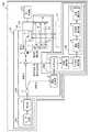
図1は、実施の形態1に係る光距離測定装置101を備えている加工装置100の構成を示す図である。なお、実施の形態1では、光距離測定装置101が加工装置100に設置されている構成について説明するが、光距離測定装置101は、加工装置100以外の装置に設置されてもよい。Hereinafter, in order to explain the present invention in more detail, embodiments for carrying out the present invention will be described with reference to the accompanying drawings.
Embodiment 1.
FIG. 1 is a diagram showing a configuration of a
例えば、光距離測定装置101は、用いる方式が波長走査干渉方式であり、医療用途の波長掃引型光干渉断層計(SS−OCT:Swept Source − Optical Coherence Tomography)に適用される(春名正光、“光コヒーレンストモグラフィ―(OCT)”、[online]、平成22年、MEDICAL PHOTONICS、[平成31年2月4日検索]、インターネット〈URL:http://www.medicalphotonics.jp/pdf/mp0001/0001_029.pdf〉)。 For example, the optical
図1が示すように、加工装置100は、光距離測定装置101、加工制御部102、及び加工部103を備えている。光距離測定装置101は、波長掃引光出力部104、光送信部105、及び信号処理部106を備えている。 As shown in FIG. 1, the
まず、波長掃引光出力部104の構成について説明する。波長掃引光出力部104は、レーザ光源1、及び掃引部2を備えている。
レーザ光源1は、連続波のレーザ光を出射する。レーザ光源1が出射したレーザ光は、掃引部2に導かれる。実施の形態1に係るレーザ光源1は、例えば、所定の中心周波数のレーザ光を出射するガスレーザ又は半導体レーザ等の光源である。First, the configuration of the wavelength sweep
The laser light source 1 emits a continuous wave laser beam. The laser light emitted by the laser light source 1 is guided to the sweep unit 2. The laser light source 1 according to the first embodiment is, for example, a light source such as a gas laser or a semiconductor laser that emits a laser beam having a predetermined center frequency.
なお、実施の形態1では、光距離測定装置101がレーザ光源1を備えている構成について説明するが、光距離測定装置101は、レーザ光源1を備えていなくてもよい。その場合、光距離測定装置101は、レーザ光源1を備える外部のレーザ光発生装置が出射したレーザ光を用いる。 In the first embodiment, the configuration in which the light
掃引部2は、レーザ光源1が出射するレーザ光の光路上に設置されている。掃引部2は、レーザ光源が出射したレーザ光を波長掃引することにより掃引光を生成する。掃引部2が生成した掃引光は、時間経過に伴って周波数が変化する連続波のレーザ光である。掃引部2が生成し、出射した掃引光は、分岐部3に導かれる。 The sweep unit 2 is installed on the optical path of the laser light emitted by the laser light source 1. The sweep unit 2 generates sweep light by sweeping the wavelength of the laser light emitted by the laser light source. The sweep light generated by the sweep unit 2 is a continuous wave laser beam whose frequency changes with the passage of time. The sweep light generated and emitted by the sweep portion 2 is guided to the branch portion 3.
なお、実施の形態1では、光距離測定装置101がレーザ光源1及び掃引部2を含む波長掃引光出力部104を備えている構成について説明するが、光距離測定装置101は、波長掃引光出力部104を備えていなくてもよい。その場合、光距離測定装置101は、レーザ光源1及び掃引部2を備える外部の掃引光発生装置が出射した掃引光を用いてもよい。 In the first embodiment, the configuration in which the optical
次に、光送信部105の構成について説明する。光送信部105は、分岐部3、光サーキュレータ4、測定光分岐部5、第1の光学系6、第2の光学系7、反射部8、及び遅延調整部9を備えている。
分岐部3は、掃引部2が出射した掃引光の光路上に設置されている。分岐部3は、掃引部2が波長掃引した掃引光を測定光と参照光とに分岐する。より詳細には、分岐部3は、掃引部2が波長掃引した連続波のレーザ光である掃引光を分岐することにより、それぞれ連続波のレーザ光である測定光及び参照光を生成する。分岐部3が生成した測定光は、光サーキュレータ4に導かれる。また、分岐部3が生成した参照光は、遅延調整部9に導かれる。Next, the configuration of the
The branch portion 3 is installed on the optical path of the sweep light emitted by the sweep portion 2. The branching unit 3 branches the sweep light swept by the wavelength of the sweeping unit 2 into the measurement light and the reference light. More specifically, the branching unit 3 branches the sweeping light, which is the continuous wave laser light whose wavelength is swept by the sweeping unit 2, to generate the measurement light and the reference light, which are the continuous wave laser light, respectively. The measurement light generated by the branch portion 3 is guided to the
分岐部3は、例えば、光カプラである。また、分岐部3が生成した測定光は、後述する測定光分岐部5によって、さらに分岐されることにより複数の測定光となる。当該複数の測定光は、互いに干渉し得る。そのため、分岐部3が生成した測定光の強度は、当該複数の測定光同士の干渉が後述する距離測定空間108の距離の測定に影響を与えない程度に、分岐部3が生成した参照光の強度よりも十分に低いことが好ましい。 The branch portion 3 is, for example, an optical coupler. Further, the measurement light generated by the branch portion 3 is further branched by the measurement
なお、光距離測定装置101は、分岐部3として、レーザ光の光路を高速にスイッチングできる光スイッチを備えていてもよい。その場合、当該光スイッチは、掃引光の光路を、当該光スイッチから光サーキュレータ4までの光路にスイッチングすることにより測定光を光サーキュレータ4に導くか、又は、掃引光の光路を、当該光スイッチから遅延調整部9までの光路にスイッチングすることにより参照光を遅延調整部9に導く。 The optical
光サーキュレータ4は、分岐部3が生成した測定光の光路上に設置されている。光サーキュレータ4は、分岐部3が生成した測定光を測定光分岐部5に導く。光サーキュレータ4は、例えば、3ポート光サーキュレータである。 The
測定光分岐部5は、光サーキュレータ4が出射した測定光の光路上に設置されている。測定光分岐部5は、分岐部3が生成した測定光を第1の測定光と第2の測定光とに分岐する。より詳細には、測定光分岐部5は、分岐部3が生成した連続波のレーザ光である測定光を分岐することにより、それぞれ連続波のレーザ光である第1の測定光と第2の測定光とを生成する。測定光分岐部5が生成した第1の測定光は、第1の光学系6に導かれる。また、測定光分岐部5が生成した第2の測定光は、第2の光学系7に導かれる。 The measurement
実施の形態1では、後述するように、第2の光学系7は、複数の光学素子10から構成されている。そこで、実施の形態1では、測定光分岐部5は、分岐部3が生成した測定光を分岐することにより、第1の測定光と、複数の光学素子10の数と同一の数の第2の測定光とを生成する。 In the first embodiment, as will be described later, the second optical system 7 is composed of a plurality of
第1の光学系6は、測定光分岐部5が出射した第1の測定光の光路上に設置されている。実施の形態1では、第1の光学系6は、後述する加工部103と共に、加工ヘッド部110を構成している。加工ヘッド部110は、加工部103が測定対象物107を加工する際に、加工制御部102の制御に基づいて、測定対象物107に対して相対的に移動する。第1の光学系6は、測定光分岐部5が分岐した第1の測定光を測定対象物107に照射し、当該測定対象物107において反射された第1の反射光を受光する。 The first
より詳細には、第1の光学系6は、例えば、少なくとも1つ以上のレンズにより構成される。当該レンズの例として、レーザ光を透過及び屈折させる透過レンズ、又はミラーを利用した反射レンズ等が挙げられる。第1の光学系6は、例えば、これらのレンズによって第1の測定光の光束径を広げ、光束径が広がった第1の測定光を測定対象物107に照射する。 More specifically, the first
測定対象物107に照射された第1の測定光は、測定対象物107において反射される。次に、第1の光学系6は、測定対象物107において反射された第1の反射光を受光する。次に、第1の光学系6が受光した第1の反射光は、測定光分岐部5に導かれ、光サーキュレータ4に導かれる。次に、光サーキュレータ4は、測定光分岐部5から導かれた第1の反射光を後述する光干渉部11に導く。 The first measurement light applied to the
第2の光学系7は、測定光分岐部5が出射した第2の測定光の光路上に設置されている。第2の光学系7は、測定光分岐部5が分岐した第2の測定光を、第1の光学系6と測定対象物107との間の空間である距離測定空間108に向けて出射する。 The second optical system 7 is installed on the optical path of the second measurement light emitted by the measurement
実施の形態1では、第2の光学系7は、複数の光学素子10から構成されている。複数の光学素子10は、第1の光学系6の光軸に平行な軸に沿って並んでいる。また、複数の光学素子10の各光軸は、第1の光学系の光軸と直交する。複数の光学素子10は、それぞれ、測定光分岐部5が分岐した第2の測定光を距離測定空間108に向けて出射する。 In the first embodiment, the second optical system 7 is composed of a plurality of
より詳細には、光学素子10は、例えば、レンズであり、第2の光学系7は、例えば、少なくとも1つ以上のレンズにより構成される。当該レンズの例として、レーザ光を透過及び屈折させる透過レンズ、又は鏡を利用した反射レンズ等が挙げられる。第2の光学系7は、例えば、これらのレンズによって第2の測定光の光束径を広げ、光束径が広がった第2の測定光を距離測定空間108に向けて出射する。 More specifically, the
反射部8は、第2の光学系7が出射した第2の測定光の光路上に設置されている。反射部8は、第2の光学系7が出射し、距離測定空間108を通過した第2の測定光を、第2の光学系7に向けて反射する。反射部8は、例えば、ミラーである。 The
より詳細には、実施の形態1では、反射部8は、反射面が複数の光学素子10の各光軸に垂直になるように設置されている。よって、反射部8は、光学素子10が出射し、距離測定空間108を通過した第2の測定光を、当該光学素子10に向けて反射することが可能である。 More specifically, in the first embodiment, the reflecting
第2の光学系7は、第2の測定光が反射部8において反射された光である第2の反射光を受光する。実施の形態1では、複数の光学素子10は、それぞれ、出射した第2の測定光が反射部8において反射された光である第2の反射光を受光する。次に、第2の光学系7が受光した第2の反射光は、測定光分岐部5に導かれ、光サーキュレータ4に導かれる。次に、光サーキュレータ4は、測定光分岐部5から導かれた第2の反射光を光干渉部11に導く。 The second optical system 7 receives the second reflected light, which is the light reflected by the reflecting
遅延調整部9は、分岐部3が出射した参照光の光路上に設置されている。遅延調整部9は、分岐部3から光干渉部11までの参照光の経路長と、分岐部3から測定対象物107又は反射部8を経た光干渉部11までの測定光の経路長との差を調整する。これにより、遅延調整部9は、光干渉部11における、参照光と、第1の反射光又は第2の反射光との周波数差を調整する。遅延調整部9が出射した参照光は、光干渉部11に導かれる。 The
次に、信号処理部106の構成について説明する。信号処理部106は、光干渉部11、光電変換部12、デジタル変換部13、及び解析部109を備えている。
光干渉部11は、光サーキュレータ4が出射した第1の反射光及び第2の反射光の各光路と遅延調整部9が出射した参照光の光路とが交わる位置に設置されている。光干渉部11は、第1の光学系6が受光した第1の反射光と、分岐部3が分岐した参照光とを干渉させることにより第1の干渉光を生成する。実施の形態1では、光干渉部11は、光サーキュレータ4が出射した第1の反射光と、遅延調整部9が出射した参照光とを干渉させることにより第1の干渉光を生成する。Next, the configuration of the
The
また、光干渉部11は、第2の測定光が反射部8において反射され、第2の光学系7が受光した第2の反射光と、分岐部3が分岐した参照光とを干渉させることにより第2の干渉光を生成する。実施の形態1では、光干渉部11は、光サーキュレータ4が出射した第2の反射光と、遅延調整部9が出射した参照光とを干渉させることにより第2の干渉光を生成する。 Further, the
光干渉部11は、例えば、第1の反射光と参照光とを合成することにより第1の干渉光を生成し、第2の反射光と参照光とを合成することにより第2の干渉光を生成する90度光ハイブリッドである。または、光干渉部11は、例えば、光カプラである。 For example, the
光電変換部12は、光干渉部11が出射した第1の干渉光及び第2の干渉光の光路上に設置されている。光電変換部12は、光干渉部11が生成した第1の干渉光を光電変換することにより、第1の干渉光の波形を示す第1のアナログ信号を生成する。また、光電変換部12は、光干渉部11が生成した第2の干渉光を光電変換することにより、第2の干渉光の波形を示す第2のアナログ信号を生成する。 The
実施の形態1では、光距離測定装置101は、上記のような光干渉部11及び光電変換部12を備えている構成について説明するが、当該構成に限定されない。例えば、光距離測定装置101は、光干渉部11及び光電変換部12の代わりに、バランス型光受信用フォトダイオードを備えていてもよい。当該バランス型光受信用フォトダイオードは、例えば、第1の反射光を受光することにより第1の信号を生成するフォトダイオードと、参照光を受光することにより第2の信号を生成するフォトダイオードとを備え、当該第1の信号と当該第2の信号とから、第1の反射光と参照光との強度の差を示す変位信号を生成する。なお、当該変位信号を用いた距離測定方法は、公知の技術であるため、詳細な説明は省略する。 In the first embodiment, the configuration in which the optical
デジタル変換部13は、光電変換部12が生成した第1のアナログ信号をA/D変換することにより、第1の干渉光の波形を示す第1のデジタル信号を生成する。また、デジタル変換部13は、光電変換部12が生成した第2のアナログ信号をA/D変換することにより、第2の干渉光の波形を示す第2のデジタル信号を生成する。 The digital conversion unit 13 A / D-converts the first analog signal generated by the
解析部109は、強度測定部14、光路長算出部15、及び距離算出部16を備えている。強度測定部14は、デジタル変換部13が生成した第1のデジタル信号に基づいて、第1の干渉光の周波数毎の強度を測定する。強度測定部14は、測定した第1の干渉光の周波数毎の強度を光路長算出部15に出力する。
より詳細には、強度測定部14は、例えば、デジタル変換部13が生成した第1のデジタル信号をフーリエ変換することにより、第1の干渉光の周波数毎の強度を測定する。The
More specifically, the
また、強度測定部14は、デジタル変換部13が生成した第2のデジタル信号に基づいて、第2の干渉光の周波数毎の強度を測定する。強度測定部14は、測定した第2の干渉光の周波数毎の強度を光路長算出部15に出力する。
より詳細には、強度測定部14は、例えば、デジタル変換部13が生成した第2のデジタル信号をフーリエ変換することにより、第2の干渉光の周波数毎の強度を測定する。Further, the
More specifically, the
光路長算出部15は、第1の光学系6が受光した第1の反射光と、分岐部3が分岐した参照光とに基づいて、第1の光学系6の出射面から測定対象物107の反射面までの第1の光路長を算出する。光路長算出部15は、算出した第1の光路長を距離算出部16に出力する。 The optical path
より詳細には、光路長算出部15は、光干渉部11が生成した第1の干渉光に基づいて、第1の光学系6の出射面から測定対象物107の反射面までの第1の光路長を算出する。さらに詳細には、実施の形態1では、光路長算出部15は、強度測定部14が測定した第1の干渉光の周波数毎の強度に基づいて、第1の光学系6の出射面から測定対象物107の反射面までの第1の光路長を算出する。 More specifically, the optical path
また、光路長算出部15は、第2の光学系が受光した第2の反射光と、分岐部3が分岐した参照光とに基づいて、第2の光学系7の出射面から反射部8の反射面までの第2の光路長を算出する。光路長算出部15は、算出した第2の光路長を距離算出部16に出力する。 Further, the optical path
より詳細には、光路長算出部15は、光干渉部11が生成した第2の干渉光に基づいて、第2の光学系7の出射面から反射部8の反射面までの第2の光路長を算出する。さらに詳細には、実施の形態1では、光路長算出部15は、強度測定部14が測定した第2の干渉光の周波数毎の強度に基づいて、第2の光学系7の出射面から反射部8の反射面までの第2の光路長を算出する。 More specifically, the optical path
距離算出部16は、光路長算出部15が測定した第2の光路長に基づいて、距離測定空間108の屈折率を算出し、当該屈折率と、光路長算出部15が測定した第1の光路長とに基づいて、第1の光学系6の出射面から測定対象物107の反射面までの距離を算出する。距離算出部16は、算出した距離を加工制御部102に出力する。 The
なお、距離算出部16は、上記の距離に加えて、分岐部3が出射した測定光の光路上の所定の位置、又は測定光分岐部5が出射した第1の測定光の光路上の所定の位置から、測定対象物107の反射面までの距離をさらに算出してもよい。当該所定の位置は、例えば、分岐部3の位置、光サーキュレータ4の位置、又は測定光分岐部5の位置である。 In addition to the above distance, the
光干渉部11が生成する第1の干渉光は、分岐部3から測定対象物107の反射面までの距離に応じた周波数差に基づいて生じた干渉光を含む。そして、その場合、距離算出部16は、上述の第2の光路長に基づいて算出した距離測定空間108の屈折率と、分岐部3から第1の光学系6の出射面までの屈折率と、光路長算出部15が当該干渉光に基づいて測定した第1の光路長とに基づいて、第1の光学系6の出射面から測定対象物107の反射面までの距離と、分岐部3から第1の光学系6の出射面までの距離とを算出する。距離算出部16は、算出したこれらの距離の和を求めることにより、分岐部3から測定対象物107の反射面までの距離を算出する。 The first interference light generated by the
加工制御部102は、光距離測定装置101が測定した距離に基づいて、加工部103が測定対象物107を加工するように加工部103を制御する。加工部103は、加工制御部102の制御に基づいて、測定対象物107を加工する。実施の形態1では、加工部103は、加工制御部102の制御に基づいて、測定対象物107に対してレーザ光を照射することにより、測定対象物107を加工する。しかし、加工部103は、当該構成に限定されない。例えば、加工部103は、加工制御部102の制御に基づいて、測定対象物107を研磨又は切削することにより、測定対象物107を加工してもよい。 The
次に、実施の形態1に係る光距離測定装置101の解析部109による距離測定方法について図面を参照して説明する。図2は、光距離測定装置101の解析部109による距離測定方法を示すフローチャートである。なお、解析部109が図2の距離測定方法を実行する前に、強度測定部14は、デジタル変換部13から第1のデジタル信号と第2のデジタル信号とを取得しているものとする。 Next, a distance measuring method by the
図2が示すように、強度測定部14は、デジタル変換部13が生成した第1のデジタル信号に基づいて、第1の干渉光の周波数毎の強度を測定し、デジタル変換部13が生成した第2のデジタル信号に基づいて、第2の干渉光の周波数毎の強度を測定する(ステップST1)。 As shown in FIG. 2, the
次に、光路長算出部15は、強度測定部14が測定した第1の干渉光の周波数毎の強度に基づいて、第1の光学系6の出射面から測定対象物107の反射面までの第1の光路長を算出し、強度測定部14が測定した第2の干渉光の周波数毎の強度に基づいて、第2の光学系7の出射面から反射部8の反射面までの第2の光路長を算出する(ステップST2)。
次に、距離算出部16は、光路長算出部15が測定した第2の光路長に基づいて、距離測定空間108の屈折率を算出する(ステップST3)。Next, the optical path
Next, the
次に、距離算出部16は、ステップST3で算出した屈折率と、光路長算出部15が測定した第1の光路長とに基づいて、第1の光学系6の出射面から測定対象物107の反射面までの距離を算出する(ステップST4)。
なお、加工制御部102は、ステップST4で距離算出部16が算出した距離に基づいて、加工部103が測定対象物107を加工するように加工部103を制御する。Next, the
The
解析部109における、強度測定部14、光路長算出部15及び距離算出部16のそれぞれの機能は、処理回路により実現される。すなわち、解析部109は、図2に示したステップST1からステップST4までの処理を実行するための処理回路を備える。この処理回路は、専用のハードウェアであってもよいが、メモリに記憶されたプログラムを実行するCPU(Central Processing Unit)であってもよい。 The functions of the
図3Aは、解析部109の機能を実現するハードウェア構成を示すブロック図である。図3Bは、解析部109の機能を実現するソフトウェアを実行するハードウェア構成を示すブロック図である。
上記処理回路が図3Aに示す専用のハードウェアの処理回路111である場合、処理回路111は、例えば、単一回路、複合回路、プログラム化したプロセッサ、並列プログラム化したプロセッサ、ASIC(Application Specific Integrated Circuit)、FPGA(Field−Programmable Gate Array)又はこれらを組み合わせたものが該当する。FIG. 3A is a block diagram showing a hardware configuration that realizes the functions of the
When the processing circuit is the
解析部109における、強度測定部14、光路長算出部15及び距離算出部16のそれぞれの機能を別々の処理回路で実現してもよいし、これらの機能をまとめて1つの処理回路で実現してもよい。
上記処理回路が図3Bに示すプロセッサ112である場合、解析部109における、強度測定部14、光路長算出部15及び距離算出部16のそれぞれの機能は、ソフトウェア、ファームウェア又はソフトウェアとファームウェアとの組み合わせによって実現される。
なお、ソフトウェア又はファームウェアは、プログラムとして記述されてメモリ113に記憶される。The functions of the
When the processing circuit is the
The software or firmware is described as a program and stored in the
プロセッサ112は、メモリ113に記憶されたプログラムを読み出して実行することにより、解析部109における、強度測定部14、光路長算出部15及び距離算出部16のそれぞれの機能を実現する。すなわち、解析部109は、プロセッサ112によって実行されるときに、図2に示したステップST1からステップST4までの処理が結果的に実行されるプログラムを記憶するためのメモリ113を備える。 The
これらのプログラムは、解析部109における、強度測定部14、光路長算出部15及び距離算出部16の手順又は方法をコンピュータに実行させる。メモリ113は、コンピュータを、解析部109における、強度測定部14、光路長算出部15及び距離算出部16として機能させるためのプログラムが記憶されたコンピュータ可読記憶媒体であってもよい。 These programs cause a computer to execute the procedure or method of the
メモリ113には、例えば、RAM(Random Access Memory)、ROM(Read Only Memory)、フラッシュメモリ、EPROM(Erasable Programmable Read Only Memory)、EEPROM(Electrically−EPROM)などの不揮発性又は揮発性の半導体メモリ、磁気ディスク、フレキシブルディスク、光ディスク、コンパクトディスク、ミニディスク、DVDなどが該当する。 The
解析部109における、強度測定部14、光路長算出部15及び距離算出部16のそれぞれの機能について一部を専用のハードウェアで実現し、一部をソフトウェア又はファームウェアで実現してもよい。 A part of each function of the
例えば、強度測定部14は、専用のハードウェアとしての処理回路で機能を実現する。光路長算出部15及び距離算出部16については、プロセッサ112がメモリ113に記憶されたプログラムを読み出して実行することにより機能を実現してもよい。
このように、処理回路は、ハードウェア、ソフトウェア、ファームウェア又はこれらの組み合わせにより上記機能のそれぞれを実現することができる。For example, the
As described above, the processing circuit can realize each of the above functions by hardware, software, firmware, or a combination thereof.
次に、実施の形態1に係る光距離測定装置101による距離測定方法の第1の具体例について図面を参照して説明する。図4Aは、光送信部105が出射した第1の測定光が測定対象物107によって反射されている様子を示す図である。図4Aは、光送信部105から測定対象物107までの距離がX1である場合に、光送信部105が測定対象物107に第1の測定光を照射した第1の例と、光送信部105から測定対象物107までの距離がX2である場合に、光送信部105が測定対象物107に第1の測定光を照射した第2の例と、光送信部105から測定対象物107までの距離がX3である場合に、光送信部105が測定対象物107に第1の測定光を照射した第3の例とを示す。なお、ここにおける、光送信部105から測定対象物107までの距離は、分岐部3が出射した測定光の光路上の所定の位置、又は測定光分岐部5が出射した第1の測定光の光路上の所定の位置から、測定対象物107の反射面までの距離を意味するものとする。Next, a first specific example of the distance measuring method by the optical
図4Bは、光送信部105から測定対象物107までの距離が上記のX2である第2の場合の、光干渉部11における干渉前の参照光及び干渉前の第1の反射光の各波形を示すグラフである。縦軸は、周波数(Hz)を示し、横軸は経過時間(sec)を示す。4B is a case where the distance from the
掃引部2がレーザ光を波長掃引することに起因して、光干渉部11における、参照光及び第1の反射光は、それぞれ、掃引光と同様に、時間経過とともに周波数が変化する。なお、当該第1の具体例では、掃引部2が出射する掃引光における単位時間当たりの周波数変化の値は既知であるものとする。 Due to the fact that the sweep unit 2 sweeps the laser light at a wavelength, the frequencies of the reference light and the first reflected light in the
光干渉部11における第1の反射光は、光送信部105と測定対象物107との間の距離に応じて、参照光に対して遅延する。そのため、図4Bが示すように、光干渉部11における第1の反射光は、参照光に対して、時間ΔT2の分遅れている。The first reflected light in the
上述のステップST1において、強度測定部14は、上記のような参照光と第1の反射光とから生成された第1の干渉光の波形を示す第1のデジタル信号に基づいて、第1の干渉光の周波数毎の強度を測定する。例えば、参照光の最大周波数と第1の反射光の最大周波数とは、それぞれ、THzのオーダーの高い周波数である。その場合、測定光を受光及び検波する一般的な装置では、このような高い周波数の光を直接検波することは困難である。 In step ST1 described above, the
そこで、当該第1の具体例では、光干渉部11は、参照光と第1の反射光とを4光波混合することにより、干渉光として差周波を生成する。図4Bが示す例では、当該差周波は、時点T1における、参照光の周波数Frと第1の反射光の周波数F2との周波数差ΔF2を中心周波数とする干渉光である。当該ΔF2のオーダーは、数MHzのオーダーまで抑えられるため、当該ΔF2は、一般的なバランス型光受信用フォトダイオードといった装置によって十分に測定可能である。Therefore, in the first specific example, the
図4Cは、強度測定部14が、図4Bが示す時点T1において、当該差周波の波形を示す第1のデジタル信号に基づいて測定した当該差周波の周波数スペクトルを示すグラフである。縦軸は、強度(dBm)を示し、横軸は、周波数を示す。図4Cが示すように、差周波の周波数スペクトルは、中心周波数が上述のΔF2である。Figure 4C
そして、当該ΔF2は、図4Bが示すように、光干渉部11における参照光に対する第1の反射光の遅延ΔT2に比例し、当該ΔT2は、光送信部105から測定対象物107までの距離X2に比例する。Then, asshown in FIG. 4B, the ΔF 2is proportional to the delay ΔT 2 of the first reflected light with respect to the reference light in the
そこで、上述のステップST2において、光路長算出部15は、強度測定部14が測定した差周波の周波数毎の強度に基づいて、当該差周波の中心周波数ΔF2を検出し、当該ΔF2と、図4Bが示す参照光及び第1の反射光の各グラフの傾きに相当する掃引光の掃引速度とに基づいて、光干渉部11における参照光に対する第1の反射光の遅延ΔT2を算出する。そして、光路長算出部15は、当該ΔT2に基づいて、光送信部105から測定対象物107までの第1の光路長を算出する。そして、上述のステップST4において、距離算出部16は、当該第1の光路長に基づいて距離X2を算出する。Therefore, in step ST2 described above, the optical path length calculation unit 15 detects the center frequency ΔF 2 of the difference frequency based on the intensity of the difference frequency measured by the
図4Dは、図4Aに示す各場合において、第1のデジタル信号に基づいて測定した差周波の周波数スペクトルを示すグラフである。縦軸は、強度(dBm)を示し、横軸は、周波数(Hz)を示す。 FIG. 4D is a graph showing the frequency spectrum of the difference frequency measured based on the first digital signal in each case shown in FIG. 4A. The vertical axis shows the intensity (dBm), and the horizontal axis shows the frequency (Hz).
図4Aが示すように、光送信部105と測定対象物との間の距離がX2より短いX1である場合、図4Dが示すように、差周波の中心周波数ΔF1は、光送信部105と測定対象物107との間の距離がX2である場合における上述の差周波の中心周波数ΔF2よりも低くなる。この場合、光干渉部11における、参照光に対する第1の反射光の遅延は、光送信部105と測定対象物107との間の距離がX2である場合における上述の遅延ΔT2よりも小さくなる。As shown in FIG. 4A, when the distance between the
また、図4Aが示すように、光送信部105と測定対象物との間の距離がX2より長いX3である場合、図4Dが示すように、差周波の中心周波数ΔF3は、光送信部105と測定対象物107との間の距離がX2である場合における上述の差周波の中心周波数ΔF2よりも高くなる。この場合、光干渉部11における、参照光に対する第1の反射光の遅延は、光送信部105と測定対象物107との間の距離がX2である場合における上述の遅延ΔT2よりも大きくなる。Further, as shown in FIG. 4A, when the distance between the
次に、実施の形態1に係る光距離測定装置101による距離測定方法の第2の具体例について図面を参照して説明する。図5は、図1が示す光距離測定装置101における第1の光学系6、第2の光学系7及び反射部8を拡大した図である。なお、図5において、第1の光学系6が出射する第1の測定光の光軸に平行な方向をZ軸方向とし、第2の光学系7が出射する第2の測定光の光軸に平行な方向をX軸方向とする。 Next, a second specific example of the distance measuring method by the optical
加工部103による測定対象物107の加工中では、距離測定空間108において、空気の温度変化、又は加工油のミストの飛散等により、Z軸方向に沿って屈折率が異なる屈折率分布が生じる。そこで、当該第2の具体例では、距離算出部16は、当該屈折率分布を算出する。 During the processing of the object to be measured 107 by the
図5が示すように、第1の光学系6と測定対象物107との間の距離測定空間108は、第1の光学系6の光軸に沿って並んだ複数の領域から構成されているものとする。より詳細には、当該第2の具体例では、距離測定空間108は、分割後のm個の領域が第1の光学系6の光軸に沿って並ぶようにm分割されているものとする。なお、mは、2以上の正の整数である。 As shown in FIG. 5, the
当該第2の具体例では、第2の光学系7は、それぞれ出射する第2の測定光の光軸が上記の複数の領域のうちの対応する領域を通るように設置された複数の光学素子10から構成されている。複数の光学素子10は、それぞれ、第2の測定光を、上記の複数の領域のうちの対応する領域に向けて出射し、反射部8によって反射された第2の反射光を受光する。 In the second specific example, the second optical system 7 is a plurality of optical elements installed so that the optical axis of the second measurement light emitted from each of them passes through the corresponding region of the plurality of regions described above. It is composed of 10. Each of the plurality of
より詳細には、複数の光学素子10は、m個の光学素子である。m個の光学素子10は、それぞれ出射する第2の測定光の光軸がm個の領域のうちの対応する領域を通るように設置されている。 More specifically, the plurality of
また、光干渉部11は、複数の光学素子10が受光した領域毎の第2の反射光と、分岐部3が分岐した参照光とを干渉させることにより領域毎の第2の干渉光を生成する。光路長算出部15は、光干渉部11が生成した領域毎の第2の干渉光に基づいて、各領域の第2の光路長を算出する。 Further, the
また、距離算出部16は、光路長算出部15が算出した各領域の第2の光路長に基づいて、各領域の屈折率を算出し、当該各領域の屈折率に基づいて距離測定空間108の平均屈折率を算出し、当該平均屈折率と、光路長算出部15が算出した第1の光路長とに基づいて、第1の光学系6の出射面から測定対象物107の反射面までの距離を算出する。 Further, the
以下で、当該第2の具体例における距離算出部16による距離算出方法について、より詳細に説明する。当該方法では、各領域の屈折率を、n1、n2、n3・・・nmとし、各領域のZ軸方向の長さを、Lz1、Lz2、Lz3・・・Lzmとし、各領域のX軸方向の長さを、Lx1、Lx2、Lx3・・・Lxmとする。なお、ここにおける各領域のX軸方向の長さは、各光学素子10の出射面から反射部8の反射面までの距離である。また、ここにおける「長さ」は、光路長ではなく、実際の距離である。これらの値は、加工部103による測定対象物107の加工前に予め測定される。Hereinafter, the distance calculation method by the
より詳細には、まず、図5が示すように、複数の光学素子10が、第1の光学系6の光軸に平行な軸に沿って並ぶように、複数の光学素子10は、設置され、反射部8の反射面が複数の光学素子10の各光軸に垂直になるように、反射部8は、設置される。次に、距離測定空間108における屈折率が均一である状態において、光距離測定装置101は、上述の方法と同様の方法により、複数の光学素子10の各出射面から反射部8の反射面までの距離である各領域のX軸方向の長さと、第1の光学系6の出射面から測定対象物107の照射面までの距離と、を算出する。 More specifically, first, as shown in FIG. 5, the plurality of
より詳細には、当該処理では、距離測定空間108における均一の屈折率は、既知であり、光距離測定装置101の距離算出部16は、当該屈折率と、光路長算出部15が測定した第1の光路長とに基づいて、第1の光学系6の出射面から測定対象物107の反射面までの距離を算出する。また、距離算出部16は、当該屈折率と、光路長算出部15が測定した第2の光路長とに基づいて、複数の光学素子10の各出射面から反射部8の反射面までの距離である各領域のX軸方向の長さを算出する。また、光距離測定装置101は、算出した、第1の光学系6の出射面から測定対象物107の照射面までの距離に基づいて、各領域のZ軸方向の長さを算出する。つまり、加工部103による測定対象物107の加工前に、光距離測定装置101によって、上述のLx1、Lx2、Lx3・・・LxmとLz1、Lz2、Lz3・・・Lzmとを測定する。なお、複数の光学素子10の各出射面から反射部8の反射面までの距離である各領域のX軸方向の長さは、基本的に変化しないため、予め別の方法で算出又は測定されてもよい。More specifically, in the process, the uniform refractive index in the
上記のように校正のためのデータが測定された上で、加工部103による測定対象物107の加工が開始される。上述の通り、加工部103による測定対象物107の加工中では、距離測定空間108において、Z軸方向に沿って屈折率が異なる屈折率分布が生じる。距離測定空間において、このような屈折率分布が生じた場合、光距離測定装置101による距離の測定精度は低下してしまう。そこで、以下で説明するような方法によって、光距離測定装置101は、加工部103による測定対象物107の加工中における、第1の光学系6の出射面から測定対象物107の反射面までの距離を算出する。 After the data for calibration is measured as described above, the processing of the object to be measured 107 is started by the
上述のように、光路長は、屈折率と距離との積に等しいため、光路長算出部15が算出する第2の光路長は、1以上、m以下の整数iを用いて下記の式(1)のように示される。
式(1)において、Lmeasure,xiは、光路長算出部15が算出した、各領域のX軸方向の光路長を示す。Lxiは、上述の通り予め測定された、各領域のX軸方向の長さである。式(1)より、各領域の屈折率は、下記の式(2)のように表される。
式(2)が示すように、距離算出部16は、加工部103による測定対象物107の加工前に予め測定されたLxiと、加工部103による測定対象物107の加工中に光路長算出部15が算出した第2の光路長Lmeasure,xiとの比率から各領域の屈折率を算出する。また、各領域のZ軸方向の長さの合計は、下記の式(3)のように示される。
式(3)において、Lziは、上述の通り予め測定された各領域のZ軸方向の長さを示し、Lz0は、当該Lziから算出された、第1の光学系6の出射面から測定対象物107の反射面までの距離を示す。距離測定空間108の平均屈折率naveを、式(2)の各領域の屈折率niを当該各領域のZ軸方向の長さLziにより重みづけた加重平均として定義すると、下記の式(4)が成り立つ。
上記の式(4)が示すように、距離算出部16は、算出した各領域の屈折率niと、上述の通り予め測定されたLziとに基づいて、距離測定空間108の平均屈折率naveを算出する。As indicated by the equation (4), the
また、下記の式(5)が示すように、各領域のZ軸方向の光路長の合計、つまり第1の光学系6の出射面から測定対象物107の反射面までの第1の光路長Lmeasure,zは、距離測定空間108の平均屈折率naveと、第1の光学系6の出射面から測定対象物107の反射面までの距離LZとの積と等しい。
上記の式(6)が示すように、距離算出部16は、算出した平均屈折率naveと、光路長算出部15が算出した第1の光路長Lmeasure,zとに基づいて、加工部103による測定対象物107の加工中における、第1の光学系6の出射面から測定対象物107の反射面までの距離LZを算出する。As shown in the above equation (6), the
また、上記の第2の具体例において、距離測定空間108における屈折率分布が、Z軸方向の位置に応じて連続的に変化していると予想される場合、距離算出部16は、各領域の屈折率をフィッティングパラメータとして用いることにより、Z軸方向の位置に応じて連続的に変化する屈折率の関数をフィッティングにより導いてもよい。その場合、距離算出部16は、距離測定空間108の平均屈折率を、式(4)のような単純な加重平均によってではなく、当該関数を積分することによって算出してもよい。 Further, in the second specific example described above, when the refractive index distribution in the
なお、一般的に、光を用いた距離測定では、距離測定を開始してから完了するまでの間に、距離測定空間108における屈折率が、温度の変化、又は空気以外の物質の濃度の変化によって変化する度合いは、非常に小さい。 In general, in distance measurement using light, the refractive index in the
より詳細には、一般的に、波長掃引光を出射する光源は、掃引速度がkHzオーダー以上のものが広く用いられている。光距離測定装置101の波長掃引光出力部104にこのような光源が用いられた場合、光距離測定装置101は、1秒間に1000回の距離測定を行うことができる。光距離測定装置101が1回の距離測定に要する0.001秒の間に、距離測定空間108において温度の変化、又は対流による屈折率が変化する度合いは、非常に小さい。 More specifically, in general, as a light source that emits wavelength sweep light, a light source having a sweep speed on the order of kHz or more is widely used. When such a light source is used for the wavelength sweep
そのため、光距離測定装置101は、波長掃引光出力部104、複数の光学素子10及び反射部8等の光学部材による光を用いた距離測定を行うことにより、距離測定空間108の変化する屈折率を逐一測定することができる。よって、光距離測定装置101は、当該屈折率に基づいて、第1の光学系6の出射面から測定対象物107の反射面までの距離を逐一測定することができる。 Therefore, the optical
以下で、距離測定空間108における屈折率変化のシミュレーション結果について説明する。当該シミュレーションでは、測定対象物107の反射面が油膜層によって覆われており、距離測定空間108は、当該油膜層と、当該油膜層の第1の光学系6側の表面から第1の光学系6の出射面までの空気層とから構成されているものとする。 The simulation result of the change in the refractive index in the
第1の光学系6の光軸に沿った方向の当該空気層の厚さは、0.8mとし、第1の光学系6の光軸に沿った方向の当該油膜層の厚さは、0.001mとする。また、空気層の屈折率の温度依存性を3.7×10^−6とし、油膜層の屈折率の温度依存性を3.3×10^−4とする。 The thickness of the air layer in the direction along the optical axis of the first
光距離測定装置101がキロワットクラスの高出力加工レーザを出力する場合、迷光によって加工ヘッド部110全体が温度上昇する。そこで、加工部103による測定対象物107の加工中において、空気層の温度は、第1の光学系6側の厚さ0.4mの層の温度が80度であり、測定対象物107側の厚さ0.4mの層の温度が40℃であると仮定し、油膜層の温度は40℃であると仮定する。その場合において測定される、第1の光学系6の出射面から測定対象物107の反射面までの光路長と、距離測定空間108の温度が常温25℃である場合において測定される、第1の光学系6の出射面から測定対象物107の反射面までの光路長との差は、108.1umであると想定される。光距離測定装置101は、上述の方法により、この差分を補正することが可能であり、これにより、加工部103による測定対象物107の加工中における、第1の光学系6の出射面から測定対象物107の反射面までの距離を正確に測定することができる。 When the light
なお、上記のシミュレーションにおける空気の屈折率の温度依存性の値として、Ciddorの式を用いた。また、上記のシミュレーションにおける油膜の屈折率の温度依存性の値として、トルエンの物性値を用いた。一般的に、トルエンそのものは、加工油として用いられることはないが、物性値の例が豊富に蓄積されているため用いた。 In addition, Ciddor's formula was used as the temperature-dependent value of the refractive index of air in the above simulation. In addition, the physical property value of toluene was used as the temperature-dependent value of the refractive index of the oil film in the above simulation. Generally, toluene itself is not used as a processing oil, but it was used because there are abundant examples of physical characteristics.
次に、実施の形態1に係る光距離測定装置101の変形例について説明する。光干渉部11における、第1の反射光に基づいた第1の干渉光と、第2の反射光に基づいた第2の干渉光とは、光路長算出部15が各干渉光の中心周波数を検出できる程度に十分に分離される必要がある。 Next, a modified example of the light
そこで、例えば、光干渉部11に入射する第1の反射光と第2の反射光とを、カプラを用いて分岐する方法が考えられる。当該方法では、光干渉部11が、第1の反射光と第2の反射光とが干渉しない程度に十分に離れた位置において、第1の反射光と参照光との干渉、及び第2の反射光と参照光との干渉を同時に行えるように、第1の反射光の光路の長さと、第2の反射光の光路の長さとを調整する必要がある。しかし、当該方法では、第1の反射光の光路の長さを調整した分、第1の反射光の光路が長くなることにより、光距離測定装置101が測定可能な距離の範囲が狭くなる可能性がある。 Therefore, for example, a method of branching the first reflected light and the second reflected light incident on the
そこで、当該変形例では、光距離測定装置101は、測定光分岐部5として、測定光の光路を高速にスイッチングできる光スイッチを備える。当該光スイッチは、測定光の光路を、当該光スイッチから第1の光学系6までの光路にスイッチングすることにより第1の測定光を第1の光学系6に導くか、又は、測定光の光路を、当該光スイッチから第2の光学系7までの光路にスイッチングすることにより第2の測定光を第2の光学系7に導く。なお、当該光スイッチは、波長掃引光出力部104が出射する掃引光の掃引周波数よりも少ない頻度でスイッチングを行う。 Therefore, in the modification, the optical
これにより、第1の反射光と第2の反射光とは、空間的ではなく時間的に分離され、光干渉部11は、第1の反射光と参照光との干渉、及び第2の反射光と参照光との干渉をそれぞれ異なる時間に行うことができ、第1の干渉光と第2の干渉光とが時間的に分離される。よって、光路長算出部15は、各干渉光の中心周波数を正確に検出できる。従って、距離算出部16は、第1の光学系6の出射面から測定対象物107の反射面までの距離を正確に測定できる。 As a result, the first reflected light and the second reflected light are separated not spatially but temporally, and the
図6Aは、光距離測定装置101が、測定光分岐部5として、空間的に測定光を第1の測定光と第2の測定光とに分岐する光学素子を備えた場合の、光干渉部11における第1の干渉光の周波数スペクトルと第2の干渉光の周波数スペクトルとを示すグラフである。図6Aにおいて、縦軸は、強度を示し、横軸は、周波数を示す。なお、図6Aでは、第2の光学系7を構成する複数の光学素子10のうちの2つの光学素子10に対応して、第2の干渉光の周波数スペクトルが2つ示されている。 FIG. 6A shows an optical interference unit when the optical
第1の干渉光の周波数スペクトルPと、第2の干渉光の周波数スペクトルQと、第2の干渉光の周波数スペクトルRとは、光路長算出部15が各干渉光の中心周波数を検出できる程度に十分に離れている必要がある。 The frequency spectrum P of the first interference light, the frequency spectrum Q of the second interference light, and the frequency spectrum R of the second interference light are such that the optical path
図6Bは、光距離測定装置101が、測定光分岐部5として、時間的に測定光を第1の測定光と第2の測定光とに分岐する光スイッチを備えた場合の、光干渉部11における第1の干渉光の周波数スペクトルと第2の干渉光の周波数スペクトルとを示すグラフである。図6Bにおいて、各グラフの縦軸は、強度を示し、各グラフの横軸は、周波数を示す。 FIG. 6B shows an optical interference unit when the optical
図6Bの左のグラフは、光スイッチが、測定光の光路を、当該光スイッチから第1の光学系6までの光路にスイッチングすることにより第1の測定光を第1の光学系6に導いた場合の、光干渉部11における第1の干渉光の周波数スペクトルを示す。 In the graph on the left of FIG. 6B, the optical switch guides the first measurement light to the first
図6Bの真ん中のグラフは、光スイッチが、測定光の光路を、当該光スイッチから複数の光学素子10のうちの第1の光学素子までの光路にスイッチングすることにより第2の測定光を当該第1の光学素子に導いた場合の、光干渉部11における第2の干渉光の周波数スペクトルを示す。 In the graph in the middle of FIG. 6B, the optical switch switches the optical path of the measurement light to the optical path from the optical switch to the first optical element of the plurality of
図6Bの右のグラフは、光スイッチが、測定光の光路を、当該光スイッチから複数の光学素子10のうちの第2の光学素子までの光路にスイッチングすることにより第2の測定光を当該第2の光学素子に導いた場合の、光干渉部11における第2の干渉光の周波数スペクトルを示す。 In the graph on the right of FIG. 6B, the optical switch switches the optical path of the measurement light to the optical path from the optical switch to the second optical element of the plurality of
図6Bが示すように、第1の干渉光と第2の干渉光とは、時間的に分離される。よって、光路長算出部15は、各干渉光の中心周波数を正確に検出でき、距離算出部16は、第1の光学系6の出射面から測定対象物107の反射面までの距離を正確に測定できる。 As shown in FIG. 6B, the first interference light and the second interference light are temporally separated. Therefore, the optical path
以上のように、実施の形態1に係る光距離測定装置101は、レーザ光を測定光と参照光とに分岐する分岐部3と、分岐部3が分岐した測定光を第1の測定光と第2の測定光とに分岐する測定光分岐部5と、測定光分岐部5が分岐した第1の測定光を測定対象物に照射し、当該測定対象物において反射された第1の反射光を受光する第1の光学系6と、測定光分岐部5が分岐した第2の測定光を、第1の光学系6と測定対象物107との間の距離測定空間108に向けて出射する第2の光学系7と、第2の光学系7が出射し、距離測定空間108を通過した第2の測定光を、第2の光学系7に向けて反射する反射部8と、第1の光学系6が受光した第1の反射光と、分岐部3が分岐した参照光とに基づいて、第1の光学系6の出射面から測定対象物107の反射面までの第1の光路長を算出し、反射部8によって反射され、第2の光学系7が受光した第2の反射光と、分岐部3が分岐した参照光とに基づいて、第2の光学系7の出射面から反射部8の反射面までの第2の光路長を算出する光路長算出部15と、光路長算出部15が測定した第2の光路長に基づいて、距離測定空間108の屈折率を算出し、当該屈折率と、光路長算出部15が測定した第1の光路長とに基づいて、第1の光学系6の出射面から測定対象物107の反射面までの距離を算出する距離算出部16と、を備えている。 As described above, in the optical
上記の構成によれば、第2の光学系7の出射面から反射部8の反射面までの第2の光路長に基づいて距離測定空間108の屈折率を算出し、当該屈折率と、第1の光学系6の出射面から測定対象物107の反射面までの第1の光路長とに基づいて、第1の光学系6の出射面から測定対象物107の反射面までの距離を算出する。これにより、距離測定空間108の屈折率が変化する場合に、測定した距離測定空間108の屈折率に基づいて、第1の光学系6の出射面から測定対象物107の反射面までの距離を算出することができる。よって、距離測定空間108の屈折率が変化することによって距離の測定精度が低下してしまうことを抑制することができる。 According to the above configuration, the refractive index of the
また、実施の形態1に係る光距離測定装置101は、第1の光学系6が受光した第1の反射光と、分岐部3が分岐した参照光とを干渉させることにより第1の干渉光を生成し、第2の測定光が反射部8において反射され、第2の光学系7が受光した第2の反射光と、分岐部3が分岐した参照光とを干渉させることにより第2の干渉光を生成する光干渉部11をさらに備え、光路長算出部15は、光干渉部11が生成した第1の干渉光に基づいて、第1の光学系6の出射面から測定対象物107の反射面までの第1の光路長を算出し、光干渉部11が生成した第2の干渉光に基づいて、第2の光学系7の出射面から反射部8の反射面までの第2の光路長を算出する。 Further, the light
上記の構成によれば、第1の反射光と参照光との第1の干渉光に基づいて、第1の光路長を好適に算出することができ、第2の反射光と参照光との第2の干渉光に基づいて、第2の光路長を好適に算出することができる。よって、第1の光学系6の出射面から測定対象物107の反射面までの距離を好適に算出することができ、距離測定空間108の屈折率が変化することによって距離の測定精度が低下してしまうことを抑制することができる。 According to the above configuration, the first optical path length can be suitably calculated based on the first interference light between the first reflected light and the reference light, and the second reflected light and the reference light can be calculated. The second optical path length can be suitably calculated based on the second interference light. Therefore, the distance from the exit surface of the first
また、実施の形態1に係る光距離測定装置101は、距離測定空間108は、第1の光学系6の光軸に沿って並んだ複数の領域から構成され、第2の光学系7は、それぞれ出射する第2の測定光の光軸が複数の領域のうちの対応する領域を通るように設置された複数の光学素子10から構成され、複数の光学素子10は、それぞれ、第2の測定光を、複数の領域のうちの対応する領域に向けて出射し、反射部によって反射された第2の反射光を受光し、光干渉部11は、複数の光学素子10が受光した領域毎の第2の反射光と、参照光とを干渉させることにより領域毎の第2の干渉光を生成し、光路長算出部15は、光干渉部11が生成した領域毎の第2の干渉光に基づいて、各領域の第2の光路長を算出し、距離算出部16は、光路長算出部15が算出した各領域の第2の光路長に基づいて、各領域の屈折率を算出し、当該各領域の屈折率に基づいて距離測定空間108の平均屈折率を算出し、当該平均屈折率と第1の光路長とに基づいて第1の光学系6の出射面から測定対象物107の反射面までの距離を算出する。 Further, in the optical
上記の構成によれば、各領域の第2の光路長を算出する。そして、各領域の第2の光路長に基づいて、各領域の屈折率を算出し、当該各領域の屈折率と、第1の光学系6の出射面から測定対象物107の反射面までの第1の光路長とに基づいて、第1の光学系6の出射面から測定対象物107の反射面までの距離を算出する。これにより、距離測定空間108の屈折率が変化し、距離測定空間108において屈折率分布が生じる場合、測定した距離測定空間108における各領域の屈折率に基づいて、第1の光学系6の出射面から測定対象物107の反射面までの距離を算出することができる。よって、距離測定空間108の屈折率が変化し、距離測定空間において屈折率分布が生じることによって距離の測定精度が低下してしまうことを抑制することができる。 According to the above configuration, the second optical path length of each region is calculated. Then, the refractive index of each region is calculated based on the second optical path length of each region, and the refractive index of each region and the emission surface of the first
また、実施の形態1に係る光距離測定装置101は、レーザ光は、波長掃引された掃引光であり、光干渉部11は、第1の反射光と参照光とを干渉させることにより第1の干渉光として第1の差周波を生成し、第2の反射光と参照光とを干渉させることにより第2の干渉光として第2の差周波を生成し、光路長算出部15は、光干渉部11が生成した第1の差周波に基づいて、第1の光路長を算出し、光干渉部11が生成した第2の差周波に基づいて、第2の光路長を算出する。 Further, in the light
上記の構成によれば、第1の反射光と参照光との第1の干渉光である第1の差周波に基づいて、第1の光路長を好適に算出することができ、第2の反射光と参照光との第2の干渉光である第2の差周波に基づいて、第2の光路長を好適に算出することができる。よって、第1の光学系6の出射面から測定対象物107の反射面までの距離を好適に算出することができ、距離測定空間108の屈折率が変化することによって距離の測定精度が低下してしまうことを抑制することができる。 According to the above configuration, the first optical path length can be suitably calculated based on the first difference frequency which is the first interference light between the first reflected light and the reference light, and the second The second optical path length can be suitably calculated based on the second difference frequency, which is the second interference light between the reflected light and the reference light. Therefore, the distance from the exit surface of the first
また、実施の形態1に係る加工装置100は、光距離測定装置101と、測定対象物107を加工する加工部103と、光距離測定装置101が測定した距離に基づいて、加工部103が測定対象物107を加工するように加工部103を制御する加工制御部102と、を備えている。 Further, the
上記の構成によれば、距離測定空間108の屈折率が変化した場合でも、測定した距離測定空間108の屈折率に基づいて、第1の光学系6の出射面から測定対象物107の反射面までの距離を算出し、当該距離に基づいて測定対象物107を加工することができる。よって、距離測定空間108の屈折率が変化することによって距離の測定精度が低下してしまうことを抑制することができ、測定対象物107の加工精度を向上することができる。 According to the above configuration, even if the refractive index of the
実施の形態2.
実施の形態1では、測定光及び参照光の光源として、掃引光を出力する波長掃引光出力部104を用いる構成を説明した。実施の形態2では、測定光及び参照光の光源として、白色光を出力する白色レーザ光源を用いる構成を説明する。
以下で、実施の形態2について図面を参照して説明する。なお、実施の形態1で説明した構成と同様の機能を有する構成については同一の符号を付し、その説明を省略する。図7は、実施の形態2に係る光距離測定装置121を備えている加工装置120の構成を示す図である。図7が示すように、実施の形態1に係る光距離測定装置101と比較して、光距離測定装置121は、波長掃引光出力部104の代わりに、白色レーザ光源20を備え、信号処理部122が分光部21をさらに備えている。Embodiment 2.
In the first embodiment, the configuration using the wavelength sweep
Hereinafter, the second embodiment will be described with reference to the drawings. The same reference numerals are given to the configurations having the same functions as those described in the first embodiment, and the description thereof will be omitted. FIG. 7 is a diagram showing a configuration of a
白色レーザ光源20は、連続波のレーザ光を出射する。例えば、白色レーザ光源20は、ASE(Amplified Spontaneous Emission)光源等である。
なお、実施の形態2では、光距離測定装置121が白色レーザ光源20を備えている構成について説明するが、光距離測定装置121は、白色レーザ光源20を備えていなくてもよい。その場合、光距離測定装置121は、白色レーザ光源20を備える外部のレーザ光発生装置が出射したレーザ光を用いてもよい。The white
In the second embodiment, the configuration in which the light
実施の形態2では、分岐部3は、白色レーザ光源20が出射したレーザ光を測定光と参照光とに分岐する。つまり、当該測定光及び当該参照光と、測定光分岐部5が当該測定光を分岐することにより生成する第1の測定光及び第2の測定光と、第1の光学系6が測定対象物107に照射し、測定対象物107において反射された第1の反射光と、第2の光学系7が反射部8に向けて出射し、反射部8において反射された第2の反射光とは、それぞれ、連続波のレーザ光である。 In the second embodiment, the branching portion 3 branches the laser light emitted by the white
よって、実施の形態2では、光干渉部11は、連続波の第1の反射光と、連続波の参照光とを干渉させることにより第1の干渉光を生成する。また、光干渉部11は、連続波の第2の反射光と、連続波の参照光とを干渉させることにより第2の干渉光を生成する。 Therefore, in the second embodiment, the
分光部21は、光干渉部11が生成した第1の干渉光を分光する。分光部21が分光した第1の干渉光は、周波数毎に空間的に分離している。また、分光部21は、光干渉部11が生成した第2の干渉光を分光する。分光部21が分光した第2の干渉光は、周波数毎に空間的に分離している。分光部21は、例えば、回折格子等である。 The
より詳細には、実施の形態2では、光電変換部12は、図示しない複数の光電素子を有する。当該複数の光電素子は、それぞれ、分光部21が分光した第1の干渉光を光電変換することにより、各光電素子の配置が対応付けられた第1の干渉光の強度を示す第1のアナログ信号を生成する。より詳細には、光電変換部12は、例えば、CCDのようにアレイ状に並べられた複数の光電素子を有する。当該複数の光電素子は、各配置が、受光する光の周波数に対応している。当該複数の光電素子は、空間的に周波数毎に分離した第1の干渉光を光電変換することにより、各光電素子の配置が対応付けられた第1の干渉光の強度を示す第1のアナログ信号を生成する。 More specifically, in the second embodiment, the
また、実施の形態2では、光電変換部12における上述の複数の光電素子は、それぞれ、分光部21が分光した第2の干渉光を光電変換することにより、各光電素子の配置が対応付けられた第2の干渉光の強度を示す第2のアナログ信号を生成する。より詳細には、当該複数の光電素子は、空間的に周波数毎に分離した第2の干渉光を光電変換することにより、各光電素子の配置が対応付けられた第2の干渉光の強度を示す第2のアナログ信号を生成する。 Further, in the second embodiment, the plurality of photoelectric elements described above in the
実施の形態2では、デジタル変換部13は、光電変換部12が生成した第1のアナログ信号をA/D変換することにより、各光電素子の配置が対応付けられた第1の干渉光の強度を示す第1のデジタル信号を生成する。また、デジタル変換部13は、光電変換部12が生成した第2のアナログ信号をA/D変換することにより、各光電素子の配置が対応付けられた第2の干渉光の強度を示す第2のデジタル信号を生成する。 In the second embodiment, the digital conversion unit 13 A / D-converts the first analog signal generated by the
実施の形態2では、強度測定部14は、図示しない記憶部から、光電変換部12における各光電素子の配置と各光電素子が受光する光の周波数との対応を示す情報を取得する。強度測定部14は、当該情報と、デジタル変換部13が生成した第1のデジタル信号とに基づいて、第1の干渉光の周波数毎の強度を測定する。また、実施の形態2では、強度測定部14は、光電変換部12における各光電素子の配置と各光電素子が受光する光の周波数との対応を示す情報、及び、デジタル変換部13が生成した第2のデジタル信号とに基づいて、第2の干渉光の周波数毎の強度を測定する。 In the second embodiment, the
実施の形態2では、光路長算出部15は、分光部21が分光した第1の干渉光に基づいて、第1の光学系6の出射面から測定対象物107の反射面までの第1の光路長を算出する。また、実施の形態2では、光路長算出部15は、分光部21が分光した第2の干渉光に基づいて、第2の光学系7の出射面から反射部8の反射面までの第2の光路長を算出する。より詳細には、実施の形態2では、光路長算出部15は、強度測定部14が測定した第1の干渉光の周波数毎の強度に基づいて、第1の光学系6の出射面から測定対象物107の反射面までの第1の光路長を算出する。また、光路長算出部15は、強度測定部14が測定した第2の干渉光の周波数毎の強度に基づいて、第2の光学系7の出射面から反射部8の反射面までの第2の光路長を算出する。 In the second embodiment, the optical path
なお、図は省略するが、実施の形態2に係る光距離測定装置121の解析部109による距離測定方法は、実施の形態1に係る光距離測定装置101の解析部109による距離測定方法と比較して、以下の点が異なる。まず、実施の形態2では、上述のステップST1において、強度測定部14は、光電変換部12における各光電素子の配置と各光電素子が受光する光の周波数との対応を示す情報と、デジタル変換部13が生成した第1のデジタル信号とに基づいて、第1の干渉光の周波数毎の強度を測定する。 Although the figure is omitted, the distance measurement method by the
また、実施の形態2では、上述のステップST1において、強度測定部14は、光電変換部12における各光電素子の配置と各光電素子が受光する光の周波数との対応を示す情報と、デジタル変換部13が生成した第2のデジタル信号とに基づいて、第2の干渉光の周波数毎の強度を測定する。 Further, in the second embodiment, in step ST1 described above, the
次に、上述のステップST2において、光路長算出部15は、強度測定部14が測定した第1の干渉光の周波数毎の強度に基づいて、第1の光学系6の出射面から測定対象物107の反射面までの第1の光路長を算出し、強度測定部14が測定した第2の干渉光の周波数毎の強度に基づいて、第2の光学系7の出射面から反射部8の反射面までの第2の光路長を算出する。 Next, in step ST2 described above, the optical path
より詳細には、実施の形態2では、上述のステップST2において、光路長算出部15は、周知技術であるスペクトルドメイン方式の光干渉断層計に用いられる方法と同様の方法により、強度測定部14が測定した第1の干渉光の周波数毎の強度に基づいて、第1の光学系6の出射面から測定対象物107の反射面までの第1の光路長を算出する。 More specifically, in the second embodiment, in the above-mentioned step ST2, the optical path
また、実施の形態2では、上述のステップST2において、光路長算出部15は、周知技術であるスペクトルドメイン方式による光干渉断層計に用いられる方法と同様の方法により、強度測定部14が測定した第2の干渉光の周波数毎の強度に基づいて、第2の光学系7の出射面から反射部8の反射面までの第2の光路長を算出する。なお、スペクトルドメイン方式の光干渉断層計による光路長測定方法は公知であるため、説明を省略する。 Further, in the second embodiment, in step ST2 described above, the optical path
次に、距離算出部16は、上述のステップST3において、光路長算出部15が測定した第2の光路長に基づいて、距離測定空間108の屈折率を算出する。次に、上述のステップST4において、距離算出部16は、ステップST3で算出した屈折率と、光路長算出部15が測定した第1の光路長とに基づいて、第1の光学系6の出射面から測定対象物107の反射面までの距離を算出する。 Next, the
なお、実施の形態2に係る光距離測定装置121の解析部109における、強度測定部14、光路長算出部15及び距離算出部16のそれぞれの機能は、処理回路により実現される。すなわち、実施の形態2に係る光距離測定装置121の解析部109は、上記で説明した各ステップの処理を実行するための処理回路を備える。この処理回路は、専用のハードウェアであってもよいが、メモリに記憶されたプログラムを実行するCPU(Central Processing Unit)であってもよい。実施の形態2に係る光距離測定装置121の解析部109の機能を実現するハードウェア構成は、図3Aが示すハードウェア構成と同様である。また、実施の形態2に係る光距離測定装置121の解析部109の機能を実現するソフトウェアを実行するハードウェア構成は、図3Bが示すハードウェア構成と同様である。 The functions of the
以上のように、実施の形態2に係る光距離測定装置121は、レーザ光は、白色レーザ光であり、光干渉部11が生成した第1の干渉光を分光し、光干渉部11が生成した第2の干渉光を分光する分光部21をさらに備え、光路長算出部15は、分光部21が分光した第1の干渉光に基づいて、第1の光学系6の出射面から測定対象物107の反射面までの第1の光路長を算出し、分光部21が分光した第2の干渉光に基づいて、第2の光学系7の出射面から反射部8の反射面までの第2の光路長を算出する。 As described above, in the light
上記の構成によれば、分光された第1の干渉光に基づいて、第1の光路長を好適に算出することができ、分光された第2の干渉光に基づいて、第2の光路長を好適に算出することができる。よって、第1の光学系6の出射面から測定対象物107の反射面までの距離を好適に算出することができ、距離測定空間108の屈折率が変化することによって距離の測定精度が低下してしまうことを抑制することができる。
なお、本願発明はその発明の範囲内において、各実施の形態の自由な組み合わせ、あるいは各実施の形態の任意の構成要素の変形、もしくは各実施の形態において任意の構成要素の省略が可能である。According to the above configuration, the first optical path length can be suitably calculated based on the separated first interference light, and the second optical path length is based on the dispersed second interference light. Can be preferably calculated. Therefore, the distance from the exit surface of the first
It should be noted that, within the scope of the present invention, any combination of embodiments can be freely combined, any component of each embodiment can be modified, or any component can be omitted in each embodiment. ..
この発明に係る光距離測定装置は、距離測定空間の屈折率が変化することによって距離の測定精度が低下してしまうことを抑制することができるため、測定対象物を加工する加工装置に利用可能である。 The optical distance measuring device according to the present invention can be used as a processing device for processing an object to be measured because it can suppress a decrease in distance measurement accuracy due to a change in the refractive index of the distance measuring space. Is.
1 レーザ光源、2 掃引部、3 分岐部、4 光サーキュレータ、5 測定光分岐部、6 第1の光学系、7 第2の光学系、8 反射部、9 遅延調整部、10 光学素子、11 光干渉部、12 光電変換部、13 デジタル変換部、14 強度測定部、15 光路長算出部、16 距離算出部、20 白色レーザ光源、21 分光部、100 加工装置、101 光距離測定装置、102 加工制御部、103 加工部、104 波長掃引光出力部、105 光送信部、106 信号処理部、107 測定対象物、108 距離測定空間、109 解析部、110 加工ヘッド部、111 処理回路、112 プロセッサ、113 メモリ、120 加工装置、121 光距離測定装置、122 信号処理部。 1 Laser light source, 2 Sweep section, 3 Branch section, 4 Optical circulator, 5 Measurement optical branch section, 6 1st optical system, 7 2nd optical system, 8 Reflection section, 9 Delay adjustment section, 10 Optical elements, 11 Optical interference unit, 12 photoelectric conversion unit, 13 digital conversion unit, 14 intensity measurement unit, 15 optical path length calculation unit, 16 distance calculation unit, 20 white laser light source, 21 spectroscopic unit, 100 processing equipment, 101 optical distance measurement unit, 102 Machining control unit, 103 processing unit, 104 wavelength sweep light output unit, 105 optical transmission unit, 106 signal processing unit, 107 measurement target, 108 distance measurement space, 109 analysis unit, 110 processing head unit, 111 processing circuit, 112 processor , 113 memory, 120 processing device, 121 optical distance measuring device, 122 signal processing unit.
Claims (6)
Translated fromJapanese前記分岐部が分岐した測定光を第1の測定光と第2の測定光とに分岐する測定光分岐部と、
前記測定光分岐部が分岐した第1の測定光を測定対象物に照射し、当該測定対象物において反射された第1の反射光を受光する第1の光学系と、
前記測定光分岐部が分岐した第2の測定光を、前記第1の光学系と前記測定対象物との間の空間に向けて出射する第2の光学系と、
前記第2の光学系が出射し、前記空間を通過した第2の測定光を、前記第2の光学系に向けて反射する反射部と、
前記第1の光学系が受光した第1の反射光と、前記分岐部が分岐した参照光とに基づいて、前記第1の光学系の出射面から前記測定対象物の反射面までの第1の光路長を算出し、前記反射部によって反射され、前記第2の光学系が受光した第2の反射光と、前記分岐部が分岐した参照光とに基づいて、前記第2の光学系の出射面から前記反射部の反射面までの第2の光路長を算出する光路長算出部と、
前記光路長算出部が測定した第2の光路長に基づいて、前記空間の屈折率を算出し、当該屈折率と、前記光路長算出部が測定した第1の光路長とに基づいて、前記第1の光学系の出射面から前記測定対象物の反射面までの距離を算出する距離算出部と、を備えていることを特徴とする、光距離測定装置。A branch that splits the laser beam into measurement light and reference light,
A measurement light branch portion in which the measurement light branched by the branch portion is branched into a first measurement light and a second measurement light, and a measurement light branch portion.
A first optical system that irradiates the measurement object with the first measurement light branched from the measurement light branch portion and receives the first reflected light reflected by the measurement object.
A second optical system that emits the second measurement light branched from the measurement light branch portion toward the space between the first optical system and the measurement object, and the second optical system.
A reflecting unit that emits the second optical system and reflects the second measurement light that has passed through the space toward the second optical system.
Based on the first reflected light received by the first optical system and the reference light from which the branch portion is branched, the first from the emission surface of the first optical system to the reflection surface of the measurement object. The optical path length of the second optical system is calculated, and the second optical system is based on the second reflected light reflected by the reflecting portion and received by the second optical system and the reference light to which the branch portion is branched. An optical path length calculation unit that calculates a second optical path length from the emission surface to the reflection surface of the reflection unit, and a light path length calculation unit.
The refractive index of the space is calculated based on the second optical path length measured by the optical path length calculation unit, and the refractive index is calculated based on the refractive index and the first optical path length measured by the optical path length calculation unit. An optical distance measuring device comprising: a distance calculating unit for calculating a distance from an emitting surface of a first optical system to a reflecting surface of the object to be measured.
前記光路長算出部は、前記光干渉部が生成した第1の干渉光に基づいて、前記第1の光路長を算出し、前記光干渉部が生成した第2の干渉光に基づいて、前記第2の光路長を算出することを特徴とする、請求項1に記載の光距離測定装置。The first interference light is generated by interfering the first reflected light received by the first optical system with the reference light branched by the branch portion, and the second measurement light is generated in the reflection portion. Further provided with an optical interfering portion that generates a second interfering light by interfering the second reflected light that is reflected and received by the second optical system with the reference light that the branched portion is branched.
The optical path length calculation unit calculates the first optical path length based on the first interference light generated by the optical interference unit, and the optical path length calculation unit calculates the first optical path length based on the second interference light generated by the optical interference unit. The optical distance measuring device according to claim 1, wherein a second optical path length is calculated.
前記第2の光学系は、それぞれ出射する第2の測定光の光軸が前記複数の領域のうちの対応する領域を通るように設置された複数の光学素子から構成され、
前記複数の光学素子は、それぞれ、前記第2の測定光を、前記複数の領域のうちの対応する領域に向けて出射し、前記反射部によって反射された第2の反射光を受光し、
前記光干渉部は、前記複数の光学素子が受光した領域毎の第2の反射光と、前記参照光とを干渉させることにより領域毎の第2の干渉光を生成し、
前記光路長算出部は、前記光干渉部が生成した領域毎の第2の干渉光に基づいて、各領域の第2の光路長を算出し、
前記距離算出部は、前記光路長算出部が算出した各領域の第2の光路長に基づいて、各領域の屈折率を算出し、当該各領域の屈折率に基づいて前記空間の平均屈折率を算出し、当該平均屈折率と前記第1の光路長とに基づいて前記距離を算出することを特徴とする、請求項2に記載の光距離測定装置。The space is composed of a plurality of regions arranged along the optical axis of the first optical system.
The second optical system is composed of a plurality of optical elements installed so that the optical axis of the second measurement light emitted from each of them passes through the corresponding region of the plurality of regions.
Each of the plurality of optical elements emits the second measurement light toward the corresponding region of the plurality of regions, and receives the second reflected light reflected by the reflection unit.
The optical interference unit generates a second interference light for each region by interfering the second reflected light for each region received by the plurality of optical elements with the reference light.
The optical path length calculation unit calculates the second optical path length of each region based on the second interference light for each region generated by the optical interference unit.
The distance calculation unit calculates the refractive index of each region based on the second optical path length of each region calculated by the optical path length calculation unit, and the average refractive index of the space is based on the refractive index of each region. The optical distance measuring device according to claim 2, wherein the distance is calculated based on the average refractive index and the first optical path length.
前記光干渉部は、前記第1の反射光と前記参照光とを干渉させることにより前記第1の干渉光として第1の差周波を生成し、前記第2の反射光と前記参照光とを干渉させることにより前記第2の干渉光として第2の差周波を生成し、
前記光路長算出部は、前記光干渉部が生成した第1の差周波に基づいて、前記第1の光路長を算出し、前記光干渉部が生成した第2の差周波に基づいて、前記第2の光路長を算出することを特徴とする、請求項2に記載の光距離測定装置。The laser beam is a wavelength-swept sweeping light.
The optical interference unit generates a first difference frequency as the first interference light by interfering the first reflected light with the reference light, and the second reflected light and the reference light are combined with each other. By interfering with each other, a second difference frequency is generated as the second interference light.
The optical path length calculation unit calculates the first optical path length based on the first difference frequency generated by the optical interference unit, and the optical path length calculation unit calculates the first optical path length based on the second difference frequency generated by the optical interference unit. The optical distance measuring device according to claim 2, wherein a second optical path length is calculated.
前記光干渉部が生成した第1の干渉光を分光し、前記光干渉部が生成した第2の干渉光を分光する分光部をさらに備え、
前記光路長算出部は、前記分光部が分光した第1の干渉光に基づいて、前記第1の光路長を算出し、前記分光部が分光した第2の干渉光に基づいて、前記第2の光路長を算出することを特徴とする、請求項2に記載の光距離測定装置。The laser beam is a white laser beam.
A spectroscopic unit that disperses the first interference light generated by the optical interference unit and disperses the second interference light generated by the optical interference unit is further provided.
The optical path length calculation unit calculates the first optical path length based on the first interference light dispersed by the spectroscopic unit, and the second optical path length calculation unit is based on the second interference light dispersed by the spectroscopic unit. The optical distance measuring device according to claim 2, wherein the optical path length of the above is calculated.
前記測定対象物を加工する加工部と、
前記光距離測定装置が測定した距離に基づいて、前記加工部が前記測定対象物を加工するように前記加工部を制御する加工制御部と、を備えていることを特徴とする、加工装置。The optical distance measuring device according to any one of claims 1 to 5.
The processing part that processes the object to be measured and
A processing device comprising: a processing control unit that controls the processing unit so that the processing unit processes the object to be measured based on the distance measured by the light distance measuring device.
Applications Claiming Priority (1)
| Application Number | Priority Date | Filing Date | Title |
|---|---|---|---|
| PCT/JP2019/041084WO2021075046A1 (en) | 2019-10-18 | 2019-10-18 | Optical distance measurement device and machining device |
Publications (2)
| Publication Number | Publication Date |
|---|---|
| JPWO2021075046A1 JPWO2021075046A1 (en) | 2021-12-16 |
| JP6987326B2true JP6987326B2 (en) | 2021-12-22 |
Family
ID=75537757
Family Applications (1)
| Application Number | Title | Priority Date | Filing Date |
|---|---|---|---|
| JP2021552075AActiveJP6987326B2 (en) | 2019-10-18 | 2019-10-18 | Light distance measuring equipment and processing equipment |
Country Status (7)
| Country | Link |
|---|---|
| US (1) | US12379494B2 (en) |
| JP (1) | JP6987326B2 (en) |
| KR (1) | KR102447598B1 (en) |
| CN (1) | CN114514409B (en) |
| DE (1) | DE112019007724B4 (en) |
| TW (1) | TW202117359A (en) |
| WO (1) | WO2021075046A1 (en) |
Families Citing this family (1)
| Publication number | Priority date | Publication date | Assignee | Title |
|---|---|---|---|---|
| WO2023032005A1 (en)* | 2021-08-30 | 2023-03-09 | 三菱電機株式会社 | Optical measurement device |
Family Cites Families (27)
| Publication number | Priority date | Publication date | Assignee | Title |
|---|---|---|---|---|
| KR910003458B1 (en)* | 1986-12-02 | 1991-05-31 | 미쓰비시뎅끼 가부시끼가이샤 | Operating apparatus of optical disk |
| US5926594A (en)* | 1994-08-31 | 1999-07-20 | Litton Systems, Inc. | System and method for aligning and attaching optical fibers to optical waveguides, and products obtained thereby |
| JP5041616B2 (en)* | 1996-06-06 | 2012-10-03 | ザ・ボーイング・カンパニー | Methods for increasing machine accuracy |
| US6219144B1 (en)* | 1997-10-02 | 2001-04-17 | Zygo Corporation | Apparatus and method for measuring the refractive index and optical path length effects of air using multiple-pass interferometry |
| WO1999042786A1 (en)* | 1998-02-23 | 1999-08-26 | Zygo Corporation | Apparatus and methods for measuring intrinsic optical properties of a gas |
| DE19840049C5 (en) | 1998-09-02 | 2007-11-08 | Leica Geosystems Ag | Device for optical distance measurement |
| US6646723B1 (en) | 2002-05-07 | 2003-11-11 | The United States Of America As Represented By The Administrator Of The National Aeronautics And Space Administration | High precision laser range sensor |
| JP2008151542A (en)* | 2006-12-14 | 2008-07-03 | Canon Inc | Stage apparatus, control system, exposure apparatus, and device manufacturing method |
| JP2008275485A (en)* | 2007-04-27 | 2008-11-13 | Nikon Corp | Interferometer system, stage apparatus, exposure apparatus, and device manufacturing method |
| JP5216465B2 (en)* | 2008-08-01 | 2013-06-19 | 株式会社ミツトヨ | Displacement measuring device and displacement measuring method |
| US8687173B2 (en) | 2008-09-11 | 2014-04-01 | Nikon Metrology N.V. | Compact fiber optic geometry for a counter chirp FMCW coherent laser radar |
| KR20100068975A (en)* | 2008-12-15 | 2010-06-24 | (주)유비토스 | Mobile device possible length measurement of subject |
| JP5541713B2 (en)* | 2009-08-21 | 2014-07-09 | キヤノン株式会社 | Laser interferometer, processing apparatus using the same, and method of manufacturing parts |
| JP5513272B2 (en) | 2010-06-15 | 2014-06-04 | 株式会社ディスコ | Apparatus for measuring height position of workpiece held on chuck table and laser processing machine |
| EP2620742B1 (en) | 2012-01-26 | 2014-03-12 | Bundesrepublik Deutschland, vertreten durch das Bundesministerium für Wirtschaft und Technologie, dieses vertreten durch den Präsidenten der | Method for absolute length measurements and length measurement device |
| US9857159B1 (en)* | 2013-09-24 | 2018-01-02 | TVS Holdings, LLC | Velocity compensated frequency sweeping interferometer and method of using same |
| JP6257033B2 (en)* | 2014-02-05 | 2018-01-10 | 株式会社東京精密 | Distance measuring device and distance measuring method |
| DE102014004697B4 (en) | 2014-03-31 | 2018-03-29 | Baden-Württemberg Stiftung Ggmbh | System and method for distance measurement |
| JP6463051B2 (en)* | 2014-09-10 | 2019-01-30 | 株式会社トーメーコーポレーション | Optical tomography system |
| JP6503618B2 (en)* | 2015-08-26 | 2019-04-24 | 株式会社東京精密 | Distance measuring device and method thereof |
| JP6635758B2 (en)* | 2015-11-10 | 2020-01-29 | 国立大学法人電気通信大学 | Refractive index correction method, distance measuring method and distance measuring device |
| CN105509637B (en)* | 2015-11-27 | 2018-02-06 | 成都信息工程大学 | Laser wavelength correction method adopting laser wavelength correction type plane mirror laser interferometer |
| CN108957471A (en)* | 2018-06-22 | 2018-12-07 | 杭州电子科技大学 | Three-dimension measuring system based on FM-CW laser ranging |
| CN108732561B (en)* | 2018-07-01 | 2020-03-13 | 北京工业大学 | Air refractive index compensation method of laser tracking measurement system based on dual-wavelength interference |
| CN110058217A (en)* | 2019-01-25 | 2019-07-26 | 北京航天计量测试技术研究所 | A kind of link air refraction real-time compensation distance measuring method altogether |
| WO2020202547A1 (en)* | 2019-04-05 | 2020-10-08 | 三菱電機株式会社 | Optical distance measurement device |
| CN110133615A (en)* | 2019-04-17 | 2019-08-16 | 深圳市速腾聚创科技有限公司 | A kind of laser radar system |
- 2019
- 2019-10-18JPJP2021552075Apatent/JP6987326B2/enactiveActive
- 2019-10-18DEDE112019007724.4Tpatent/DE112019007724B4/enactiveActive
- 2019-10-18CNCN201980101233.1Apatent/CN114514409B/enactiveActive
- 2019-10-18KRKR1020227011373Apatent/KR102447598B1/enactiveActive
- 2019-10-18WOPCT/JP2019/041084patent/WO2021075046A1/ennot_activeCeased
- 2020
- 2020-03-12TWTW109108149Apatent/TW202117359A/enunknown
- 2022
- 2022-03-17USUS17/697,189patent/US12379494B2/enactiveActive
Also Published As
| Publication number | Publication date |
|---|---|
| JPWO2021075046A1 (en) | 2021-12-16 |
| US12379494B2 (en) | 2025-08-05 |
| KR20220046710A (en) | 2022-04-14 |
| CN114514409B (en) | 2023-07-14 |
| CN114514409A (en) | 2022-05-17 |
| WO2021075046A1 (en) | 2021-04-22 |
| KR102447598B1 (en) | 2022-09-26 |
| DE112019007724B4 (en) | 2023-05-25 |
| DE112019007724T5 (en) | 2022-06-23 |
| US20220206145A1 (en) | 2022-06-30 |
| TW202117359A (en) | 2021-05-01 |
Similar Documents
| Publication | Publication Date | Title |
|---|---|---|
| JP5575600B2 (en) | Temperature measuring method, storage medium, program | |
| US8144332B2 (en) | Temperature measurement apparatus and method | |
| JP6765579B2 (en) | Optical ranging device and processing device | |
| KR101537854B1 (en) | Apparatus for measuring thickness and method for measuring thickness for the same | |
| JP6494067B2 (en) | Distance measuring device and distance measuring method | |
| KR102859530B1 (en) | Optical measurement apparatus, wavelength calibration method and standard sample | |
| JP6956918B2 (en) | Light distance measuring device | |
| JP7066075B1 (en) | Optical measuring device | |
| US20250224225A1 (en) | Optical measuring device, acquisition method, and recording medium | |
| JP6987326B2 (en) | Light distance measuring equipment and processing equipment | |
| JP6479465B2 (en) | Substrate processing apparatus and substrate temperature measuring apparatus | |
| WO2010113985A1 (en) | Interferometer | |
| WO2013015349A1 (en) | Optical tomographic image measuring apparatus and optical tomographic image measuring system | |
| JP6686201B2 (en) | Distance measuring device and distance measuring method | |
| JP7407179B2 (en) | Calibration system for attenuated total internal reflection spectroscopy measurements | |
| JP7206576B2 (en) | Measuring method and equipment | |
| JP5376284B2 (en) | Interferometry method and interferometer | |
| WO2010119561A1 (en) | Laser ranging method and laser ranging device | |
| JP2006078446A (en) | Interference measuring method and interference measuring apparatus | |
| JP2022138828A (en) | Spectrum measurement method and spectrum measurement device | |
| JP2024059119A (en) | measuring device |
Legal Events
| Date | Code | Title | Description |
|---|---|---|---|
| A621 | Written request for application examination | Free format text:JAPANESE INTERMEDIATE CODE: A621 Effective date:20210909 | |
| A871 | Explanation of circumstances concerning accelerated examination | Free format text:JAPANESE INTERMEDIATE CODE: A871 Effective date:20210909 | |
| TRDD | Decision of grant or rejection written | ||
| A01 | Written decision to grant a patent or to grant a registration (utility model) | Free format text:JAPANESE INTERMEDIATE CODE: A01 Effective date:20211102 | |
| A61 | First payment of annual fees (during grant procedure) | Free format text:JAPANESE INTERMEDIATE CODE: A61 Effective date:20211130 | |
| R150 | Certificate of patent or registration of utility model | Ref document number:6987326 Country of ref document:JP Free format text:JAPANESE INTERMEDIATE CODE: R150 | |
| R250 | Receipt of annual fees | Free format text:JAPANESE INTERMEDIATE CODE: R250 |