JP6986609B2 - Chair type massage machine - Google Patents
Chair type massage machineDownload PDFInfo
- Publication number
- JP6986609B2 JP6986609B2JP2020153537AJP2020153537AJP6986609B2JP 6986609 B2JP6986609 B2JP 6986609B2JP 2020153537 AJP2020153537 AJP 2020153537AJP 2020153537 AJP2020153537 AJP 2020153537AJP 6986609 B2JP6986609 B2JP 6986609B2
- Authority
- JP
- Japan
- Prior art keywords
- backrest
- human body
- waist
- footrest
- chair
- Prior art date
- Legal status (The legal status is an assumption and is not a legal conclusion. Google has not performed a legal analysis and makes no representation as to the accuracy of the status listed.)
- Active
Links
Images


Landscapes
- Chair Legs, Seat Parts, And Backrests (AREA)
- Chairs For Special Purposes, Such As Reclining Chairs (AREA)
- Massaging Devices (AREA)
Description
Translated fromJapaneseこの発明は、座部と背もたれ部を有する椅子式マッサージ機に関し、より詳しくは、マッサージに加えてストレッチもできるような椅子式マッサージ機に関する。 The present invention relates to a chair-type massage machine having a seat portion and a backrest portion, and more particularly to a chair-type massage machine capable of stretching in addition to massage.
椅子式マッサージ機では、人体に施療具を当ててマッサージするほか、座部と背もたれ部を備えることの利点を生かして、身体をのばすストレッチも行えるようにしたものが提案されている。 A chair-type massage machine has been proposed that not only massages the human body by applying a treatment tool, but also makes it possible to stretch the body by taking advantage of having a seat and a backrest.
ストレッチができる椅子式マッサージ機としては、たとえば下記特許文献1、2、3に開示されたものがある。 Examples of the chair-type massage machine capable of stretching include those disclosed in the following
特許文献1の椅子式マッサージ機は、座部の前端に設けられたフットレストで脚をホールドしながらフットレストを降下させて、脚を伸ばすストレッチができるようにしたものである。 The chair-type massage machine of
この椅子式マッサージ機では、脚に対してストレッチ効果が得られるものの、その他の部位、特に腰部に対してストレッチを行うことはできない。 Although this chair-type massage machine has a stretching effect on the legs, it cannot stretch on other parts, especially the lumbar region.
この点、特許文献2の椅子式マッサージ機のように、全身に対してストレッチができるようにしたものがある。この椅子式マッサージ機は、背もたれ部を後方に倒してフットレストを持ち上げた状態からフットレストを下げるように構成されている。フットレストには脚の膝より下の部分を掴持する掴持手段を備え、脚を伸ばして仰向けに反った人体の膝より下の部分を、掴持手段で固定した状態のままフットレストを下方に回転して下に引っ張るという動作を行う。これによって全身のストレッチが可能であるとされている。 In this respect, there is a chair-type massage machine of
しかし、人体は仰向けになっており、引っ張るのは膝より下の部分であり、脚は膝を中心に曲がるので、引っ張っても伸びる部分は膝より少し上の部分から下の、しかも脚の上側つまり前側の筋肉だけである。 However, the human body is lying on its back, and the part that is pulled is below the knee, and the leg bends around the knee, so the part that extends even if pulled is slightly above and below the knee, and above the leg. In other words, only the anterior muscle.
このため、ストレッチ効果は脚のうちでも膝を中心にした部分のみである。 For this reason, the stretching effect is only on the part of the leg centered on the knee.
全身にストレッチができるとする椅子式マッサージ機は、下記特許文献3にも開示されている。この椅子式マッサージ機は、特許文献2のようにあらかじめ背もたれ部を倒しておくのではなく、座部の後端近傍を回転中心として起倒自在に設けられた背もたれ部のリクライニング機構を利用してストレッチを行えるよう構成したものである。 A chair-type massage machine capable of stretching the whole body is also disclosed in Patent Document 3 below. This chair-type massage machine does not tilt the backrest in advance as in
つまり、脚部エアバッグを膨張させて人体の脚を拘束し、この状態で背もたれ部を傾倒動作させるというものである。この構成であると、人体は膝より下の部分が固定された状態で上半身が後方に倒れるので、身体が伸びる。特許文献2の構成とは違って、上半身全体を後方に大きく倒すので、全身を伸ばせるようにも思える。 That is, the leg airbag is inflated to restrain the legs of the human body, and the backrest is tilted in this state. With this configuration, the upper body of the human body falls backward with the part below the knees fixed, so the body stretches. Unlike the structure of
しかしながら、背もたれ部を後方に倒すと、背もたれ部と上半身との間では、背もたれ部の傾倒に伴って相対移動が起こる。つまり、倒れる背もたれ部の上を、人体の上半身は背もたれ部に対して相対的に下にずれるような関係になる。このため、背もたれ部の傾倒時に上半身は、背もたれ部上で位置をとどめることなく、ずり下がる。このため、リクライニング動作自体をストレッチに有効に活用することはできない。筋肉の緊張なしに身体が伸びた状態になるのは、リクライニング動作が完了した時点であり、この状態は、単に背もたれを倒して身体を反らせるのと大差のないものである。 However, when the backrest is tilted backward, relative movement occurs between the backrest and the upper body as the backrest tilts. In other words, the relationship is such that the upper body of the human body shifts downward relative to the backrest on the backrest that falls. Therefore, when the backrest is tilted, the upper body slides down without staying on the backrest. Therefore, the reclining motion itself cannot be effectively used for stretching. The body is stretched without muscle tension when the reclining motion is complete, which is not much different from simply tilting the backrest and bending the body.
また、背もたれ部の傾倒だけで上半身を倒すので、人体は腰部分を中心に上半身のみが倒れる動きとなり、腹筋や腸腰筋等に力が入りやすい状態になる。このため、腰を中心とした部分が緊張してしまい、十分にリラックスした状態でストレッチを行うことはできない。腰の弱い利用者には、負担をかけるおそれもある。 In addition, since the upper body is tilted only by tilting the backrest, only the upper body of the human body is tilted around the waist, and the abdominal muscles, iliopsoas muscles, and the like are easily stressed. For this reason, the part centered on the waist becomes tense, and it is not possible to stretch in a sufficiently relaxed state. It may put a burden on users who are weak.
このように、椅子式マッサージ機において全身を伸ばすストレッチを行うことは、容易ではなかった。また、腰部に対してストレッチが行えるようにした椅子式マッサージ機は、これまでになかった。 In this way, it was not easy to stretch the whole body with a chair-type massage machine. In addition, there has never been a chair-type massage machine that allows stretching to the lower back.
そこで、この発明は、腰部周りと、この部分を中心とした全身的なストレッチが効果的に行えるようにすることを主な目的とする。 Therefore, the main object of the present invention is to enable effective stretching around the lumbar region and around this region.
そのための手段は、座部の後方に起立傾倒可能な背もたれ部を備えた椅子式マッサージ機であって、前記座部が前後方向に移動可能に備えられるとともに、該座部の前方への移動と前記背もたれ部の後方への傾倒が同期するように構成され、前記背もたれ部の左右両側には、人体の肩部分を保持する肩ホールド手段を備え、該肩ホールド手段で人体の両肩部分を保持した状態のまま前記背もたれ部を後方に傾倒する腰部ストレッチ動作を可能にした椅子式マッサージ機である。 The means for this is a chair-type massage machine provided with a backrest that can stand and tilt behind the seat, and the seat is provided so as to be movable in the front-rear direction, and the seat can be moved forward. The backrest portion is configured to be tilted backward in synchronization with each other, and shoulder holding means for holding the shoulder portion of the human body are provided on both left and right sides of the backrest portion, and both shoulder portions of the human body are held by the shoulder holding means. It is a chair-type massage machine that enables a waist stretching operation in which the backrest is tilted backward while the backrest is in a relaxed state.
この構成では、肩ホールド手段で人体の両肩部分を保持して、背もたれ部を起立させた状態から後方へ傾倒する腰部ストレッチ動作を行うと、人体の上半身は背もたれ部に支えられながら後方に倒れる。このとき、肩ホールド手段が人体の肩部分を保持するので、背もたれ部に対して相対的に下がろうとする上半身を支え、背もたれ部の傾動に伴って人体を伸ばす。このとき、背もたれ部の傾倒に同期して座部が前方に移動するので、特に腰部分と、腰部分を中心とした部分が、余計な緊張を伴わずに伸びる。背もたれ部が完全に倒れた状態では、腰部分を中心とした全身的なストレッチ状態が得られる。 In this configuration, when both shoulders of the human body are held by the shoulder holding means and the waist stretching motion is performed in which the backrest is tilted backward from the standing state, the upper body of the human body is supported by the backrest and falls backward. .. At this time, since the shoulder holding means holds the shoulder portion of the human body, the upper body that tends to lower relative to the backrest portion is supported, and the human body is extended as the backrest portion tilts. At this time, since the seat portion moves forward in synchronization with the tilt of the backrest portion, the waist portion and the portion centered on the waist portion are particularly stretched without extra tension. When the backrest is completely collapsed, a general stretch state centered on the waist can be obtained.
以上のように、この発明によれば、背もたれ部の後方への傾動と座部の前方への移動による人体の姿勢変化と体重移動を、肩ホールド手段を用いることによって腰部を中心としたストレッチに有効利用できるようにしたので、これまで不可能であった腰部周りのストレッチが可能である。腰部分のストレッチができることから、腰部分を中心として全身的なストレッチも可能となる。 As described above, according to the present invention, the posture change and the weight shift of the human body due to the backward tilting of the backrest and the forward movement of the seat can be stretched around the lumbar region by using the shoulder holding means. Since it can be used effectively, it is possible to stretch around the waist, which was not possible before. Since the waist can be stretched, it is possible to stretch the whole body around the waist.
この発明を実施するための一形態を、以下図面を用いて説明する。
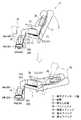
図1は、椅子式マッサージ機11で腰部ストレッチ動作を行っている状態を示す説明図である。腰部ストレッチ動作は、人体の腰部と、腰部を中心とした部分を伸ばすための動作である。An embodiment for carrying out the present invention will be described below with reference to the drawings.
FIG. 1 is an explanatory diagram showing a state in which a chair-
腰部ストレッチ動作を可能とする椅子式マッサージ機11は、座部12と、この座部12の後方で起立傾倒可能な背もたれ部13を備えている。 The chair-
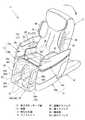
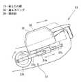
図2が、その椅子式マッサージ機11の斜視図で、図3がその側面図である。これらの図に示すように、椅子式マッサージ機11は、基台14に支持された前記座部12および背もたれ部13と、これらの左右両側に設けられたアームレスト15と、座部12の前端部に軸支され回動可能に設けられたフットレスト16を備えている。 FIG. 2 is a perspective view of the chair-
この椅子式マッサージ機11の座部12は、図2に矢印で示したように、前後方向に移動可能であるとともに、背もたれ部13はリクライニング可能に構成されている。これら座部12と背もたれ部13は連動機構によって連結されており、図4にも示したように、座部12の前方への移動と背もたれ部13の後方への傾倒が同期するように構成されている。 As shown by the arrows in FIG. 2, the
座部12が前方に移動するときには、座部12の前端部に軸支された前記フットレスト16も前方に移動する。前記フットレスト16の回動は、背もたれ部13を起立させた状態でも、傾倒させた状態でも行える。また、アームレスト15の上部の腕施療部15aは、座部12の前後動に連動するように連結されている。つまり、座部12が前方に移動するときに腕施療部15aが後方に移動する。 When the
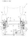
このような動きを実現するため、椅子式マッサージ機11は次のような構造を有している。図5、図6は、椅子式マッサージ機11の側面視の概略形状と内部構造を示し、図5は背もたれ部13の起立状態、図6は背もたれ部13の傾倒状態を示す。 In order to realize such a movement, the chair-
これらの図に示すように椅子式マッサージ機11は、前記基台14を構成する基台フレーム41と、前記座部12を構成し前記基台フレーム41に支持された状態で前後方向に往復動可能な座部フレーム21と、前記背もたれ部13を構成し前記座部フレーム21に回転可能に連結された背もたれフレーム31と、前記腕施療部15aを支持する腕支持体51と、前記フットレスト16を構成するフットレストフレーム(図示せず)を備えている。 As shown in these figures, the chair-
前記基台フレーム41は、角型鋼管を組んで構成され、前後方向に延びる左右両側の2本の基底材42と、これら基底材42の上に間隔をあけて立設される複数本ずつの垂直材43を有する。 The
前記複数本の垂直材43は、椅子式マッサージ機11の前方のものほど長く形成され、複数本の垂直材43の上端位置を直線でつなぐと、その直線が後方ほど低い適宜の角度で傾くように配設されている。これらの左右両側の垂直材43の上端部に、前記座部フレーム21を前後動可能に支持する座部レール44が固定される。つまり、前記座部12の前後動の軌道は、前方ほど高くなるように傾くものである。 The plurality of
前記座部レール44よりも左右方向の外側に、前記腕支持体51を前後動可能に支持する腕部レール45が支持されている。座部レール44と腕部レール45は平行である。 An
具体的には、前記垂直材43のうち前方に位置する2本の垂直材43の上端部であって座部レール44のすぐ下の位置に、左右方向の外側に突出する固定凸部46を備え、これら固定凸部46に、上下方向に延びる支持連結杆47が固定されている。2本の支持連結杆47は、側面視において、座部レール44と直交する方向に延び、互いに平行である。 Specifically, a fixed
これら支持連結杆47の長さは、座部レール44の上端面よりも上に突出する長さである。支持連結杆47の長手方向の中間部は、座部レール44と平行に延びる連結杆48で連結され、上端部は、前記腕部レール45で連結されている。つまり、腕部レール45は基台フレーム41の左右方向外側から離間支持して形成されており、座部レール44の左右方向の外側であって座部レール44よりも高い位置に、座部レール44と平行に設けられている。 The length of these
このような腕部レール45に、前記腕支持体51を介して前記腕施療部15aを前後動可能に備える。このとき、腕施療部15aは、図7に示したように、腕施療部15aの左右方向の中間位置が腕部レール45の真上または略真上に位置するように備えられる。 The
前記座部フレーム21の左右両側には、前記座部レール44に対して上から被さって前後方向に移動する前後方向に長い左右一対のスライダ22が設けられている。スライダ22は、縦断面視略逆U字形状である。これらスライダ22は左右方向に延びる複数本の連結材23で左右に連結されて一体となっている。 On both the left and right sides of the
座部フレーム21が前記のように左右両側のスライダ22を連結材23で連結した構成であり、左右のスライダ22が基台フレーム41の左右両側の垂直材43上に固定された座部レール44に被さっているので、座部フレーム21が前後動可能でありながらも、図7に示したように座部フレーム21は座部レール44を拘束するような構成となる。 The
前記スライダ22と連結材23のほかに、座部フレーム21には、前端位置の上端において左右方向に延びる前端横架材24と、左右両側で起立し座部フレーム21と共に前後動する起立壁25(図7参照)と、前記スライダ22よりも下方位置に設けられた枠状の支持枠26を有する。この支持枠26も角型鋼管を組んで構成されている。 In addition to the
前記前端横架材24を含む座部フレーム21の上面部は、図1〜図4に示したように、人体の脚における大腿部の裏側の上部と下部に対応する位置に設けられた膨張収縮するエアバッグ27(大腿部上部エアバッグ27aと大腿部下部エアバッグ27b)とクッション材(図示せず)等を内蔵して、すわり心地の良い座面を得るように形成している。前記エアバッグ27は施療具であり、前記大腿部上部エアバック27aは、左右に分けてそれぞれ2枚ずつ備えられ、前記大腿部下部エアバッグ27bは、左右一体で1枚備えられている。 As shown in FIGS. 1 to 4, the upper surface portion of the
前記起立壁25の左右方向の内側面には、人体の大腿部の外側面にマッサージを行うとともに、人体の大腿部を挟み付けて保持する腰横ホールド手段としての腰横エアバッグ28が備えられている。 On the inner side surface of the
前記前端横架材24の長手方向における中間部の下方位置と前記基台フレーム41の底部との間には、前記座部フレーム21を座部レール44に沿って前後動させるリクライニング用伸縮機構18aが相対回転可能に設けられている。リクライニング用伸縮機構18aは伸縮するもので、伸長時に座部12を前方に移動させる。 A reclining
前記背もたれフレーム31は、図5、図6に示したように、下端に、前方に向けて突出する連結部32を有する。この連結部32は、前記座部フレーム21の後端部であって前記スライダ22の上面よりも上方の位置に設けられた枢着部29に回転可能に連結されている。 As shown in FIGS. 5 and 6, the
また、背もたれフレーム31における前記枢着部29よりも後方(上方)には、前記連結部32と同様に前方に向けて突出する上部連結部33が形成され、この上部連結部33が、前記背もたれ部13の起立傾倒に伴って傾動可能な支持杆49に回転可能に支持されている。この支持杆49の下端は、基台フレーム41の後部の垂直材43に枢支される。 Further, behind (above) the pivoted
このように支持されているので、背もたれフレーム31は、座部フレーム21の前方への移動に伴って、下端部を座部フレーム21の下に潜り込ませるように相対変位しつつ前方に移動し、リクライニング動作をする。 Since it is supported in this way, the
背もたれ部13の人体の腰に対応する部位には、施療具としての膨張収縮する腰エアバック34が設けられている。この腰エアバッグ34は左右に分けて配設されている。 A
また背もたれ部13における左右両側の人体の肩に対応する部位には、人体の肩部分を挟み付けて保持する肩ホールド手段を備えている。肩ホールド手段は、施療具としての膨張収縮する肩エアバッグ35とこれを支持する隆起部36で構成されている。肩エアバッグ35は、複数枚重ねて設けるとよく、長手方向の長さは長めに設定するとよい。膨張時の形状保持力が高まり、肩部分を強力に支持できるからである。 Further, the shoulder holding means for sandwiching and holding the shoulder portion of the human body is provided at the portion of the
前記座部フレーム21には、前記背もたれ部13のほかに、座部12の前方への移動を腕施療部15aの後方への移動に変換する変換機構17を備える。 In addition to the
この変換機構17は、図8に示したように、前記座部レール21よりも左右方向の外側の位置にある前記連結杆48に回転可能に枢支された傾動リンク71と、この傾動リンク71の両端部にそれぞれ回転可能に連結された連結リンク72,73で構成されている。2本の連結リンク72,73のうち、座部フレーム21のスライダ22との間を連結するものが座側連結リンク72で、腕施療部15aの腕支持体51との間を連結するものが腕側連結リンク73である。 As shown in FIG. 8, the
座側連結リンク72の先端は、スライダ22の後方の下端部の外側面に回転可能に連結されている。腕側連結リンク73の先端は、腕支持体51の左右方向外側の側面に回転可能に連結されている。 The tip of the seat
変換機構17は、座部フレーム21の移動量L1よりも腕支持体51の移動量L2を小さくするように設定されている。移動量は、背もたれ部13を倒したときに人体の腕の位置が保てるように適宜設定される。 The
前記アームレスト15は、図2、図5、図6に示したように、前記座部12の下方の部分と、前記基台フレーム41を隠ぺいする壁状であって、前記腕施療部15aとこれを支持する本体部15bからなる。 As shown in FIGS. 2, 5, and 6, the
腕施療部15aは、図2に示したように、上面に開口52を有する。この開口52は腕(手を含めた前腕)をすっぽり収められる大きさで、深さも腕が十分に入るように設定されている。腕施療部15aの前端には、前端を閉じる平面視U字形状の閉塞壁53が形成されている。腕施療部15a内には、腕に対して施療する複数枚の腕エアバッグ54が設けられている。 As shown in FIG. 2, the
前記フットレスト16は、図5〜図8に示したように、前記座部フレーム21の支持枠26の下端後部に一端が回転可能に連結されたフットレスト用伸縮機構18bの伸縮で回動可能である。フットレスト用伸縮機構18bは、前記フットレスト16を垂直姿勢から水平姿勢まで上下方向に回動させるものである。垂直姿勢は人体の脚を垂らした状態にする姿勢で、ここでいう垂直姿勢とは、垂直のほか略垂直の状態を含む意味である。水平姿勢は、人体の脚を水平にのばした状態にする姿勢で、ここでいう水平姿勢とは、水平のほか略水平の状態を含む意味である。フットレスト用伸縮機構18bを伸長させるとフットレスト16は水平姿勢となり、縮めると垂直姿勢となる。 As shown in FIGS. 5 to 8, the
フットレスト16は、人体における脚のひざ部分より下側の部分をすっぽり収められる大きさで左右一対の凹部61を有する。フットレスト61は長手方向に複数のフットレスト担体62,63からなり、フットレスト61を人体の脚の長手方向に伸縮可能とすべく、前記フットレスト担体62,63同士の間を離したり接近させたりする周知の伸縮機構(図示せず)を備えている。また、各フットレスト担体62,63には、施療具として人体の脚に対してマッサージを行うとともに、その脚を挟み付けるようにして保持する脚ホールド手段を備えている。 The
脚ホールド手段は、膨張収縮する脚エアバッグ64で構成され、脚の脛部分の左右を挟むように膨張する脚側面エアバッグ64aと、足の左右を挟むように膨張する足側面エアバッグ64bと、ふくらはぎ部分を押圧する脚裏側エアバッグ64c、足裏を押圧する足裏エアバッグ64dを有する。 The leg holding means includes a
前記各エアバッグ27,28,34,35,54,64と図示しない他のもみ玉等の施療具、そのほか前記リクライニング用伸縮機構18a、フットレスト用伸縮機構18b、フットレストの伸縮機構18cは、図9に示したように、制御部91によって動作が制御される。制御部91は、マイクロコンピュータなどで構成され、操作パネル92からの入力に従って、あらかじめ記憶させたプログラムに基づいてエア生成手段93と、このエア生成手段93から送られるエアを分配する分配器94、リクライニング用伸縮機構18a等を駆動制御する。左右に分けて配設される各エアバッグ27a,28,34,35,54,64a,64b,64cは、それぞれ独立して膨張収縮ができるように接続されている。記憶部95には、前記プログラムのほか、使用者が所望する各部の角度情報などの必要な情報が記憶される。 The
前記プログラムは、例えば、全身をマッサージするコースモードや、上半身のみをマッサージするコースモード、下半身のみをマッサージするコースモードなどの自動コースモードのほか、使用者が所望する部位をマッサージするポイントモードなど適宜のマッサージモードである。前記腰部ストレッチ動作を行う腰部ストレッチモードは、前記自動コースモードの中に組み込むか、前記ポイントモードと同様に単独で利用できるように設定される。 The program may include, for example, an automatic course mode such as a course mode for massaging the whole body, a course mode for massaging only the upper body, a course mode for massaging only the lower body, and a point mode for massaging a part desired by the user. Massage mode. The waist stretch mode for performing the waist stretch operation is set to be incorporated in the automatic course mode or to be used independently like the point mode.
以上のように構成された椅子式マッサージ機11では、背もたれ部13を起立させた状態や後ろに適宜角度で倒した状態にして、肩ホールド手段や腰横ホールド手段、脚ホールド手段を含めた各エアバッグ27,28,34,35,54,64などの施療具によって所望のマッサージを人体の各部に対して行う。そして、前記腰部ストレッチモードでは、次のようにストレッチがなされる。 In the chair-
以下、腰部ストレッチモードの一例について説明する。
図1は腰部ストレッチモードの一例を示す。各種のマッサージモード中に腰部ストレッチ動作に入った場合や腰部ストレッチモードが選択された場合で、背もたれ部13が起立状態にないときには、まず、制御部91はリクライニング用伸縮機構18aを駆動して背もたれ部13を起立させ、あらかじめ記憶された腰部ストレッチモード初期状態にする。このとき、フットレスト16は実線で示したような垂直姿勢でも、仮想線で示したような水平姿勢でも、いずれでもよい。Hereinafter, an example of the waist stretch mode will be described.
FIG. 1 shows an example of a waist stretch mode. When the lumbar stretch mode is entered during various massage modes or when the lumbar stretch mode is selected and the
腰部ストレッチモード初期状態にしてから所定時間後、制御部91は肩エアバッグ35を膨張して、人体の両肩を左右両側から挟み込んで背もたれ部13に対して保持する。図面では、膨張したエアバッグに水平な平行線を施している。以下、同じである。 After a predetermined time from the initial state of the waist stretch mode, the
肩エアバッグ35による挟み込みの後、制御部91は、リクライニング用伸縮機構18aを伸長させて、座部12を前方に移動させるとともに、背もたれ部13を後方に倒す。リクライニング用伸縮機構18aを伸ばしきったのち、制御部91は、あらかじめ設定した所定時間を計時する。 After being pinched by the
この腰部ストレッチモードでは、肩エアバッグ35の他に、腰横エアバッグ28、または脚エアバッグ64の少なくとも一方を膨張させて、人体の腰部より下側の部分を保持し、より下方へ引っ張られる力が働くように設定してもよい。また、腰部ストレッチモードにおいて、腰エアバッグ34や大腿部上部エアバッグ27a、大腿部下部エアバッグ27bを必要に応じて膨張させることもできる。 In this waist stretch mode, in addition to the
図10は、背もたれ部13を傾倒させることのほかに、フットレスト16の動作も加えて腰部ストレッチを行うようにした腰部ストレッチモードの一例である。フットレスト16の動作は、フットレスト16を伸長して、人体の脚を水平方向に伸ばすものである。 FIG. 10 is an example of a waist stretch mode in which the
まず、制御部91は、背もたれ部13とフットレスト16が、あらかじめ記憶させた腰部ストレッチモード初期状態にない場合には、リクライニング用伸縮機構18aとフットレスト用伸縮機構18bと、フットレストの伸縮機構18cを駆動して、腰部ストレッチモード初期状態にする。この場合の腰部ストレッチモード初期状態は、背もたれ部13が起立し、フットレスト16が垂直姿勢であり、フットレスト16が縮んだ状態である。 First, the
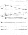
つぎに、腰部ストレッチモード初期状態にしてから所定時間後、図11のタイムチャートに例示したように、制御部91は肩エアバッグ35と腰横エアバッグ28を膨張して、人体の両肩部分と腰横部分を保持する。このあと制御部91は、フットレスト用伸縮機構18bを伸長させてフットレスト16を上方に回動する。フットレスト用伸縮機構18bの伸長開始から少し遅れた所定時間後に、リクライニング用伸縮機構18aも伸長させて背もたれ部13を倒す。 Next, after a predetermined time from the initial state of the waist stretch mode, the
また、フットレスト用伸縮機構18bが伸長しきる所定時間前に、脚エアバッグ64の膨張を開始する。フットレスト用伸縮機構18bが伸長しきる所定時間前とは、脚エアバッグ64が膨張するのに要する時間である。 Further, the
つづいて、フットレスト16が水平姿勢になった後、未だ背もたれ部13が傾倒動作をしているときに、フットレスト16の伸縮機構18cを駆動して、フットレスト16を伸長させる。フットレスト16を水平姿勢にして伸ばし、背もたれ部13を倒しきった状態で、制御部91は所定時間を計時する。 Subsequently, after the
この腰部ストレッチモードでは、腰横エアバッグ28を膨張させないで行うこともできる。また、腰エアバッグ34や大腿部上部エアバッグ27a、大腿部下部エアバッグ27bを必要に応じて膨張させることも可能である。 This waist stretch mode can also be performed without inflating the
図12は、背もたれ部13を傾倒させることのほかに、フットレスト16の動作も加えて腰部ストレッチを行うようにした腰部ストレッチモードの他の例である。フットレスト16の動作は、フットレスト16を水平姿勢から垂直姿勢に姿勢変更して、人体の脚を下方に引っ張るものである。 FIG. 12 is another example of the waist stretch mode in which the
まず、制御部91は、背もたれ部13とフットレスト16が、あらかじめ記憶させた腰部ストレッチモード初期状態にない場合には、リクライニング用伸縮機構18aとフットレスト用伸縮機構18bと、フットレストの伸縮機構18cを駆動して、腰部ストレッチモード初期状態にする。この場合の腰部ストレッチモード初期状態は、背もたれ部13が起立し、フットレスト16が水平姿勢であり、フットレスト16が縮んだ状態である。 First, the
つぎに、腰部ストレッチモード初期状態にしてから所定時間後、図13のタイムチャートに例示したように、制御部91は肩エアバッグ35と腰横エアバッグ28と脚エアバッグ64を膨張して、人体の両肩部分と腰横部分と脚を椅子式マッサージ機11の対応箇所に保持する。 Next, after a predetermined time from the initial state of the waist stretch mode, as illustrated in the time chart of FIG. 13, the
このあと制御部91は、リクライニング用伸縮機構18aを伸長させて、座部12を前方に移動させるとともに、背もたれ部13を後方に倒し、同時に、フットレスト用伸縮機構18bを縮める。フットレスト用伸縮機構18bを縮め動作の開始は、リクライニング用伸縮機構18aの動作開始と同時ではなく、適宜時間遅らせてもよい。そして、制御部91は、背もたれ部13を倒しきって、フットレスト16を垂直姿勢にした状態のまま、あらかじめ設定された所定時間を計時する。 After that, the
この腰部ストレッチモードでは、腰横エアバッグ28を膨張させないで行うこともできる。また、必要に応じて、腰エアバッグ34や大腿部上部エアバッグ27a、大腿部下部エアバッグ27bを膨張させてもよい。 This waist stretch mode can also be performed without inflating the
これらのような腰部ストレッチモードによる腰部ストレッチ動作の後は、制御部91は、あらかじめ設定された自動コースモードの次の動作に移行するか、各部をあらかじめ記憶した姿勢にして動作を終了する。 After the waist stretching operation by the waist stretching mode as described above, the
腰部ストレッチ動作では、背もたれ部13が倒れることによって、人体の上半身は、背もたれ部13の傾倒に伴って倒れて仰向けに寝るような姿勢になる。このとき、人体の肩部分は、背もたれ部13上で挟まれて拘束されているので、背もたれ部13の傾倒に伴って相対的に下がろうとする上半身が支えられる。 In the waist stretching motion, the
また、背もたれ部13の傾倒に伴って座部12は前方に移動するので、人体の臀部は座部12の移動に従って前方斜め上に引っ張られる。しかも、背もたれ部13は、リクライニングに際して一点を支点として後方に倒れるのではなく、移動可能な2点で支えられ、座部12の前方への移動に伴って倒れる。 Further, since the
このため、人体の腰部分と、腰部分を中心とした部分が、身体を反り返らすのとは違った状態で伸ばされる。この伸びは、背もたれ部13の傾動と座部12の前方斜め上への移動の過程でなされるとともに、背もたれ部13が倒れきった状態でもなされる。しかも、人体は背もたれ部13と座部12の連動で伸ばされるので腰部分がスッと伸びる。特に座部12は斜め上に向けて前方に移動するので、肩エアバッグ35で保持された人体の腰部が若干浮くような状態になり、人体に無理な負荷をかけることはない。 For this reason, the waist portion of the human body and the portion centered on the waist portion are stretched in a state different from that of bending the body. This extension is performed in the process of tilting the
したがって、腰部等に余計な緊張をもたらすことはなく、腸腰筋など、これまでの椅子式マッサージ機ではできなかった部分のストレッチが人体の腰部に負担をかけずに自然な状態で効果的に行える。 Therefore, it does not bring extra tension to the lumbar region, and stretching of parts such as the iliopsoas muscle, which was not possible with conventional chair-type massage machines, is effective in a natural state without burdening the lumbar region of the human body. You can.
背もたれ部が完全に倒れた状態では、腰部分を中心とした全身的なストレッチ状態が得られる。このストレッチによって、緊張に基づく凝りをとり、疲れなどを癒すことができる。 When the backrest is completely collapsed, a general stretch state centered on the waist can be obtained. With this stretch, you can relieve stiffness based on tension and heal tiredness.
このようなストレッチ動作に加えて、アームレスト15の腕施療部15aが、背もたれ部13の傾倒、つまり座部12の前方への移動に伴って後方に移動するので、人体の腕の位置が後ろに大きくずれないで済む。このため、全身のリラックス状態を保つことができ、腰部分という身体における中心的な部分から全体にわたる全身的なストレッチが可能である。 In addition to such a stretching motion, the
特に、背もたれ部13の傾倒時に、腰横エアバッグ28や脚エアバッグ64を膨張させて人体の腰より下側の部分を積極的に固定すると、自重のみで固定状態を得た場合に比べて、ストレッチ効果を高めることができる。 In particular, when the
さらに、フットレスト16の動作も加えることによって、脚とこれに繋がる部分にも積極的にストレッチができるので、より全身的なストレッチが行える。脚等に対してストレッチが行えることによって、身体の腰部周辺のストレッチもより効果的なものとなる。 Furthermore, by adding the movement of the
以下、その他例について説明する。この説明において、先の構成と同一または同等の部位については同一の符号を付してその詳しい説明を省略する。
図14に示したように、肩エアバッグ35を背もたれ部13の長手方向に沿って手動又は電動により移動可能にしてもよい。Hereinafter, other examples will be described. In this description, parts that are the same as or equivalent to the above configuration are designated by the same reference numerals and detailed description thereof will be omitted.
As shown in FIG. 14, the
このような肩エアバッグ35を備えると、使用者の体格の違いに対応できるほか、肩エアバッグ35で人体を伸長方向に積極的に牽引することもできる。 When such a
肩エアバッグ35による人体の牽引は、背もたれ部13を倒して行う前述の腰部ストレッチ動作に際して行う。すなわち、背もたれ部13の傾倒に伴って、肩エアバッグ35を上昇させると、より強いストレッチが行える。 The traction of the human body by the
肩エアバッグ35による人体の牽引は、背もたれ部13を傾倒させるストレッチとは別に、単独で行うこともできる。つまり、牽引動作のみで腰部ストレッチまたは上半身を中心としたストレッチを行うこともできる。牽引動作のみでストレッチを行う場合には、背もたれ部を倒した状態で行うとよい。 The traction of the human body by the
肩エアバッグ35による人体の牽引のみによるストレッチは、前述の腰部ストレッチモードに代えて行えるようにすることも、それとは別のストレッチモードとして併設することもできる。 Stretching only by pulling the human body by the
図15は、人体の上半身の牽引に利用できる駆動機構の一例を示している。すなわち、前記隆起部36を背もたれ部から分割して備え、この隆起部36にスライダクランク機構37を備えた例である。スライダクランク機構37は、隆起部36に設けられたスライダ37aと、このスライダ37aをスライド可能に保持する直線状のレール37bと、前記スライダに回転可能に連結された連結節37cと、連結節37cを回転可能に連結し、適宜のアクチュエータで回転させられる円板状のクランク37dで構成されている。
このほかの構成を採用してもよい。FIG. 15 shows an example of a drive mechanism that can be used to pull the upper body of the human body. That is, it is an example in which the raised
Other configurations may be adopted.
この発明の構成と前記一形態の構成との対応において、
この発明の肩ホールド手段は、前記肩エアバッグ35、隆起部36に対応し、
以下同様に、
腰横ホールド手段は、前記腰横エアバッグ28に対応し、
脚ホールド手段は、前記脚エアバッグ64に対応するも、
この発明は前記構成のみに限定されるものではなく、その他の構成を採用することもできる。In the correspondence between the configuration of the present invention and the configuration of the above-mentioned one form,
The shoulder holding means of the present invention corresponds to the
Similarly below
The waist lateral holding means corresponds to the
Although the leg holding means corresponds to the
The present invention is not limited to the above-mentioned configuration, and other configurations may be adopted.
例えば、背もたれ部の傾動を、座部の前後動のための駆動手段とは別の手段で行って、それらの駆動制御において両者が連動するように構成してもよい。 For example, the tilting of the backrest portion may be performed by a means different from the driving means for the back-and-forth movement of the seat portion, and both may be configured to interlock in the drive control thereof.
また、腕施療部を省略することもできる。 In addition, the arm treatment section can be omitted.
11…椅子式マッサージ機
12…座部
13…背もたれ部
16…フットレスト
28…腰横エアバッグ
29…枢着部
35…肩エアバッグ
36…隆起部
49…支持杆
64…脚エアバッグ11 ... Chair-
Claims (4)
Translated fromJapanese前記背もたれ部の左右両側には、人体の肩部分を左右から挟み付けて保持する肩ホールド手段を備え、
前記肩ホールド手段は、前記背もたれ部から分割して前記背もたれ部の両側部に前方に突出して配される隆起部と、前記隆起部の対向面に配されるエアバッグと、前記隆起部に設けられたスライダと、前記スライダをスライド可能に保持する直線状のレールと、を有して、前記背もたれ部の長手方向に沿って移動可能であり、
前記肩ホールド手段が前記背もたれ部に対して上昇して人体を牽引する、椅子式マッサージ機。It is a chair-type massage machine with a backrest behind the seat.
On both the left and right sides of the backrest portion, shoulder holding means for sandwiching and holding the shoulder portion of the human body from the left and right are provided.
The shoulder holding means is provided on the raised portion, which is divided from the backrest portion and is arranged so as to project forward on both sides of the backrest portion, an airbag arranged on the facing surface of the raised portion, and the raised portion. It has a slider and a linear rail that holds the slider slidably , and is movable along the longitudinal direction of the backrest portion.
A chair-type massage machine in which the shoulder holding means rises with respect to the backrest portion to pull the human body.
前記フットレストを水平姿勢に配して前記背もたれ部を傾倒した状態で、前記肩ホールド手段が前記背もたれ部に沿って上昇して人体を牽引する、請求項1に記載の椅子式マッサージ機。A rotatably provided footrest is provided at the front end of the seat.
The chair-type massage machine accordingto claim 1, wherein the shoulder holding means rises along the backrest and pulls the human body in a state where the footrest is arranged in a horizontal posture and the backrest is tilted.
前記背もたれ部を後方に倒した状態、又は前記背もたれ部の後方への傾倒に伴って、前記肩ホールド手段が前記背もたれ部に対して上昇して人体を牽引する、請求項1または請求項2に記載の椅子式マッサージ機。The backrest can be tilted upright,
According to claim 1 or 2 , the shoulder holding means rises with respect to the backrest and pulls the human body in a state where the backrest is tilted backward or when the backrest is tilted backward. The chair-type massage machine described.
前記肩ホールド手段が前記背もたれ部に対して上昇して人体を牽引するときに、前記腰横ホールド手段または前記脚ホールド手段の少なくとも一方で人体の腰部より下側の部分を保持する、請求項1〜3のいずれか一項に記載の椅子式マッサージ機。It comprises at least one of a lateral hip holding means for holding the lateral waist portion of the human body or a leg holding means for holding the legs of the human body.
1 ~ The chair-type massage machine according to any one of3.
Priority Applications (1)
| Application Number | Priority Date | Filing Date | Title |
|---|---|---|---|
| JP2020153537AJP6986609B2 (en) | 2020-06-04 | 2020-09-14 | Chair type massage machine |
Applications Claiming Priority (2)
| Application Number | Priority Date | Filing Date | Title |
|---|---|---|---|
| JP2020097421AJP6934088B2 (en) | 2017-11-28 | 2020-06-04 | Chair type massage machine |
| JP2020153537AJP6986609B2 (en) | 2020-06-04 | 2020-09-14 | Chair type massage machine |
Related Parent Applications (1)
| Application Number | Title | Priority Date | Filing Date |
|---|---|---|---|
| JP2020097421ADivisionJP6934088B2 (en) | 2017-11-28 | 2020-06-04 | Chair type massage machine |
Publications (2)
| Publication Number | Publication Date |
|---|---|
| JP2021006260A JP2021006260A (en) | 2021-01-21 |
| JP6986609B2true JP6986609B2 (en) | 2021-12-22 |
Family
ID=79193189
Family Applications (1)
| Application Number | Title | Priority Date | Filing Date |
|---|---|---|---|
| JP2020153537AActiveJP6986609B2 (en) | 2020-06-04 | 2020-09-14 | Chair type massage machine |
Country Status (1)
| Country | Link |
|---|---|
| JP (1) | JP6986609B2 (en) |
Families Citing this family (1)
| Publication number | Priority date | Publication date | Assignee | Title |
|---|---|---|---|---|
| JP2024537907A (en)* | 2021-10-22 | 2024-10-16 | ボディーフレンド カンパニー リミテッド | Massage device for lower back traction |
Family Cites Families (4)
| Publication number | Priority date | Publication date | Assignee | Title |
|---|---|---|---|---|
| JPH11225848A (en)* | 1998-02-19 | 1999-08-24 | Tatsuo Takahashi | Chair |
| JP4563673B2 (en)* | 2003-12-26 | 2010-10-13 | 株式会社フジ医療器 | Massage machine |
| JP4736750B2 (en)* | 2005-11-25 | 2011-07-27 | パナソニック電工株式会社 | Massage machine |
| JP5635136B2 (en)* | 2013-01-19 | 2014-12-03 | ファミリーイナダ株式会社 | Chair type massage machine |
- 2020
- 2020-09-14JPJP2020153537Apatent/JP6986609B2/enactiveActive
Also Published As
| Publication number | Publication date |
|---|---|
| JP2021006260A (en) | 2021-01-21 |
Similar Documents
| Publication | Publication Date | Title |
|---|---|---|
| JP4943202B2 (en) | Chair massage machine | |
| JP6302180B2 (en) | Chair massage machine | |
| JP2010502259A (en) | Adjustable chair adapted to various positions and its usage | |
| JP4236164B2 (en) | Massage machine | |
| JP4789742B2 (en) | Chair type massage machine | |
| JP6300002B2 (en) | Stretching equipment | |
| JP5405724B2 (en) | Massage machine | |
| JP6986609B2 (en) | Chair type massage machine | |
| JP6713976B2 (en) | Chair type massage machine | |
| JP6934088B2 (en) | Chair type massage machine | |
| JP5437184B2 (en) | Massage machine | |
| JP2006204334A (en) | Massage machine | |
| JP6948445B2 (en) | Chair type massage machine | |
| CN103156752A (en) | Swing device | |
| JP2008012055A (en) | Chair type massage machine | |
| JP5946734B2 (en) | Chair type massage machine | |
| JP2005218511A (en) | Chair | |
| JP5199605B2 (en) | Massage machine | |
| JP4789739B2 (en) | Chair type massage machine | |
| JP5557944B2 (en) | Massage machine | |
| JP5800355B2 (en) | Chair type massage machine | |
| JP2012005718A (en) | Passive exercise apparatus | |
| JP4653668B2 (en) | Chair | |
| JP2008049084A (en) | Massaging machine | |
| JP5732300B2 (en) | Standing assist device |
Legal Events
| Date | Code | Title | Description |
|---|---|---|---|
| A621 | Written request for application examination | Free format text:JAPANESE INTERMEDIATE CODE: A621 Effective date:20200914 | |
| A131 | Notification of reasons for refusal | Free format text:JAPANESE INTERMEDIATE CODE: A131 Effective date:20210622 | |
| A521 | Request for written amendment filed | Free format text:JAPANESE INTERMEDIATE CODE: A523 Effective date:20210816 | |
| A02 | Decision of refusal | Free format text:JAPANESE INTERMEDIATE CODE: A02 Effective date:20210914 | |
| A521 | Request for written amendment filed | Free format text:JAPANESE INTERMEDIATE CODE: A523 Effective date:20211005 | |
| C60 | Trial request (containing other claim documents, opposition documents) | Free format text:JAPANESE INTERMEDIATE CODE: C60 Effective date:20211005 | |
| A911 | Transfer to examiner for re-examination before appeal (zenchi) | Free format text:JAPANESE INTERMEDIATE CODE: A911 Effective date:20211012 | |
| C21 | Notice of transfer of a case for reconsideration by examiners before appeal proceedings | Free format text:JAPANESE INTERMEDIATE CODE: C21 Effective date:20211019 | |
| TRDD | Decision of grant or rejection written | ||
| A01 | Written decision to grant a patent or to grant a registration (utility model) | Free format text:JAPANESE INTERMEDIATE CODE: A01 Effective date:20211116 | |
| A61 | First payment of annual fees (during grant procedure) | Free format text:JAPANESE INTERMEDIATE CODE: A61 Effective date:20211129 | |
| R150 | Certificate of patent or registration of utility model | Ref document number:6986609 Country of ref document:JP Free format text:JAPANESE INTERMEDIATE CODE: R150 | |
| R250 | Receipt of annual fees | Free format text:JAPANESE INTERMEDIATE CODE: R250 |