JP6986603B2 - Insertion module and insertion device with it - Google Patents
Insertion module and insertion device with itDownload PDFInfo
- Publication number
- JP6986603B2 JP6986603B2JP2020131738AJP2020131738AJP6986603B2JP 6986603 B2JP6986603 B2JP 6986603B2JP 2020131738 AJP2020131738 AJP 2020131738AJP 2020131738 AJP2020131738 AJP 2020131738AJP 6986603 B2JP6986603 B2JP 6986603B2
- Authority
- JP
- Japan
- Prior art keywords
- sheet
- needle
- auxiliary
- wing
- wing portions
- Prior art date
- Legal status (The legal status is an assumption and is not a legal conclusion. Google has not performed a legal analysis and makes no representation as to the accuracy of the status listed.)
- Active
Links
- 238000003780insertionMethods0.000titleclaimsdescription202
- 230000037431insertionEffects0.000titleclaimsdescription202
- 230000004308accommodationEffects0.000claims6
- 230000008878couplingEffects0.000description7
- 238000010168coupling processMethods0.000description7
- 238000005859coupling reactionMethods0.000description7
- 230000000903blocking effectEffects0.000description5
- 238000000605extractionMethods0.000description3
- 239000000853adhesiveSubstances0.000description2
- 230000001070adhesive effectEffects0.000description2
- WQZGKKKJIJFFOK-GASJEMHNSA-NGlucoseNatural productsOC[C@H]1OC(O)[C@H](O)[C@@H](O)[C@@H]1OWQZGKKKJIJFFOK-GASJEMHNSA-N0.000description1
- 238000000354decomposition reactionMethods0.000description1
- 238000010586diagramMethods0.000description1
- 230000000694effectsEffects0.000description1
- 239000008103glucoseSubstances0.000description1
- 238000004519manufacturing processMethods0.000description1
- 239000002906medical wasteSubstances0.000description1
- 238000012986modificationMethods0.000description1
- 230000004048modificationEffects0.000description1
- 230000002093peripheral effectEffects0.000description1
Images


Classifications
- A—HUMAN NECESSITIES
- A61—MEDICAL OR VETERINARY SCIENCE; HYGIENE
- A61B—DIAGNOSIS; SURGERY; IDENTIFICATION
- A61B5/00—Measuring for diagnostic purposes; Identification of persons
- A61B5/145—Measuring characteristics of blood in vivo, e.g. gas concentration or pH-value ; Measuring characteristics of body fluids or tissues, e.g. interstitial fluid or cerebral tissue
- A61B5/14532—Measuring characteristics of blood in vivo, e.g. gas concentration or pH-value ; Measuring characteristics of body fluids or tissues, e.g. interstitial fluid or cerebral tissue for measuring glucose, e.g. by tissue impedance measurement
- A—HUMAN NECESSITIES
- A61—MEDICAL OR VETERINARY SCIENCE; HYGIENE
- A61B—DIAGNOSIS; SURGERY; IDENTIFICATION
- A61B5/00—Measuring for diagnostic purposes; Identification of persons
- A61B5/0002—Remote monitoring of patients using telemetry, e.g. transmission of vital signals via a communication network
- A61B5/0004—Remote monitoring of patients using telemetry, e.g. transmission of vital signals via a communication network characterised by the type of physiological signal transmitted
- A—HUMAN NECESSITIES
- A61—MEDICAL OR VETERINARY SCIENCE; HYGIENE
- A61B—DIAGNOSIS; SURGERY; IDENTIFICATION
- A61B5/00—Measuring for diagnostic purposes; Identification of persons
- A61B5/145—Measuring characteristics of blood in vivo, e.g. gas concentration or pH-value ; Measuring characteristics of body fluids or tissues, e.g. interstitial fluid or cerebral tissue
- A61B5/14503—Measuring characteristics of blood in vivo, e.g. gas concentration or pH-value ; Measuring characteristics of body fluids or tissues, e.g. interstitial fluid or cerebral tissue invasive, e.g. introduced into the body by a catheter or needle or using implanted sensors
- A—HUMAN NECESSITIES
- A61—MEDICAL OR VETERINARY SCIENCE; HYGIENE
- A61B—DIAGNOSIS; SURGERY; IDENTIFICATION
- A61B5/00—Measuring for diagnostic purposes; Identification of persons
- A61B5/145—Measuring characteristics of blood in vivo, e.g. gas concentration or pH-value ; Measuring characteristics of body fluids or tissues, e.g. interstitial fluid or cerebral tissue
- A61B5/14507—Measuring characteristics of blood in vivo, e.g. gas concentration or pH-value ; Measuring characteristics of body fluids or tissues, e.g. interstitial fluid or cerebral tissue specially adapted for measuring characteristics of body fluids other than blood
- A61B5/1451—Measuring characteristics of blood in vivo, e.g. gas concentration or pH-value ; Measuring characteristics of body fluids or tissues, e.g. interstitial fluid or cerebral tissue specially adapted for measuring characteristics of body fluids other than blood for interstitial fluid
- A—HUMAN NECESSITIES
- A61—MEDICAL OR VETERINARY SCIENCE; HYGIENE
- A61B—DIAGNOSIS; SURGERY; IDENTIFICATION
- A61B5/00—Measuring for diagnostic purposes; Identification of persons
- A61B5/145—Measuring characteristics of blood in vivo, e.g. gas concentration or pH-value ; Measuring characteristics of body fluids or tissues, e.g. interstitial fluid or cerebral tissue
- A61B5/14546—Measuring characteristics of blood in vivo, e.g. gas concentration or pH-value ; Measuring characteristics of body fluids or tissues, e.g. interstitial fluid or cerebral tissue for measuring analytes not otherwise provided for, e.g. ions, cytochromes
- A—HUMAN NECESSITIES
- A61—MEDICAL OR VETERINARY SCIENCE; HYGIENE
- A61B—DIAGNOSIS; SURGERY; IDENTIFICATION
- A61B5/00—Measuring for diagnostic purposes; Identification of persons
- A61B5/145—Measuring characteristics of blood in vivo, e.g. gas concentration or pH-value ; Measuring characteristics of body fluids or tissues, e.g. interstitial fluid or cerebral tissue
- A61B5/1468—Measuring characteristics of blood in vivo, e.g. gas concentration or pH-value ; Measuring characteristics of body fluids or tissues, e.g. interstitial fluid or cerebral tissue using chemical or electrochemical methods, e.g. by polarographic means
- A61B5/1486—Measuring characteristics of blood in vivo, e.g. gas concentration or pH-value ; Measuring characteristics of body fluids or tissues, e.g. interstitial fluid or cerebral tissue using chemical or electrochemical methods, e.g. by polarographic means using enzyme electrodes, e.g. with immobilised oxidase
- A61B5/14865—Measuring characteristics of blood in vivo, e.g. gas concentration or pH-value ; Measuring characteristics of body fluids or tissues, e.g. interstitial fluid or cerebral tissue using chemical or electrochemical methods, e.g. by polarographic means using enzyme electrodes, e.g. with immobilised oxidase invasive, e.g. introduced into the body by a catheter or needle or using implanted sensors
- A—HUMAN NECESSITIES
- A61—MEDICAL OR VETERINARY SCIENCE; HYGIENE
- A61B—DIAGNOSIS; SURGERY; IDENTIFICATION
- A61B5/00—Measuring for diagnostic purposes; Identification of persons
- A61B5/15—Devices for taking samples of blood
- A61B5/150007—Details
- A61B5/150748—Having means for aiding positioning of the piercing device at a location where the body is to be pierced
- A—HUMAN NECESSITIES
- A61—MEDICAL OR VETERINARY SCIENCE; HYGIENE
- A61B—DIAGNOSIS; SURGERY; IDENTIFICATION
- A61B5/00—Measuring for diagnostic purposes; Identification of persons
- A61B5/15—Devices for taking samples of blood
- A61B5/150007—Details
- A61B5/150847—Communication to or from blood sampling device
- A—HUMAN NECESSITIES
- A61—MEDICAL OR VETERINARY SCIENCE; HYGIENE
- A61B—DIAGNOSIS; SURGERY; IDENTIFICATION
- A61B5/00—Measuring for diagnostic purposes; Identification of persons
- A61B5/68—Arrangements of detecting, measuring or recording means, e.g. sensors, in relation to patient
- A61B5/6801—Arrangements of detecting, measuring or recording means, e.g. sensors, in relation to patient specially adapted to be attached to or worn on the body surface
- A61B5/683—Means for maintaining contact with the body
- A61B5/6832—Means for maintaining contact with the body using adhesives
- A61B5/6833—Adhesive patches
- A—HUMAN NECESSITIES
- A61—MEDICAL OR VETERINARY SCIENCE; HYGIENE
- A61B—DIAGNOSIS; SURGERY; IDENTIFICATION
- A61B5/00—Measuring for diagnostic purposes; Identification of persons
- A61B5/68—Arrangements of detecting, measuring or recording means, e.g. sensors, in relation to patient
- A61B5/6846—Arrangements of detecting, measuring or recording means, e.g. sensors, in relation to patient specially adapted to be brought in contact with an internal body part, i.e. invasive
- A61B5/6847—Arrangements of detecting, measuring or recording means, e.g. sensors, in relation to patient specially adapted to be brought in contact with an internal body part, i.e. invasive mounted on an invasive device
- A61B5/6848—Needles
- A61B5/6849—Needles in combination with a needle set
- A—HUMAN NECESSITIES
- A61—MEDICAL OR VETERINARY SCIENCE; HYGIENE
- A61B—DIAGNOSIS; SURGERY; IDENTIFICATION
- A61B5/00—Measuring for diagnostic purposes; Identification of persons
- A61B5/68—Arrangements of detecting, measuring or recording means, e.g. sensors, in relation to patient
- A61B5/6846—Arrangements of detecting, measuring or recording means, e.g. sensors, in relation to patient specially adapted to be brought in contact with an internal body part, i.e. invasive
- A61B5/6867—Arrangements of detecting, measuring or recording means, e.g. sensors, in relation to patient specially adapted to be brought in contact with an internal body part, i.e. invasive specially adapted to be attached or implanted in a specific body part
- A—HUMAN NECESSITIES
- A61—MEDICAL OR VETERINARY SCIENCE; HYGIENE
- A61B—DIAGNOSIS; SURGERY; IDENTIFICATION
- A61B2560/00—Constructional details of operational features of apparatus; Accessories for medical measuring apparatus
- A61B2560/04—Constructional details of apparatus
- A61B2560/0443—Modular apparatus
- A61B2560/045—Modular apparatus with a separable interface unit, e.g. for communication
- A—HUMAN NECESSITIES
- A61—MEDICAL OR VETERINARY SCIENCE; HYGIENE
- A61B—DIAGNOSIS; SURGERY; IDENTIFICATION
- A61B2560/00—Constructional details of operational features of apparatus; Accessories for medical measuring apparatus
- A61B2560/06—Accessories for medical measuring apparatus
- A61B2560/063—Devices specially adapted for delivering implantable medical measuring apparatus
- A—HUMAN NECESSITIES
- A61—MEDICAL OR VETERINARY SCIENCE; HYGIENE
- A61B—DIAGNOSIS; SURGERY; IDENTIFICATION
- A61B2562/00—Details of sensors; Constructional details of sensor housings or probes; Accessories for sensors
- A61B2562/02—Details of sensors specially adapted for in-vivo measurements
- A61B2562/0295—Strip shaped analyte sensors for apparatus classified in A61B5/145 or A61B5/157
- A—HUMAN NECESSITIES
- A61—MEDICAL OR VETERINARY SCIENCE; HYGIENE
- A61B—DIAGNOSIS; SURGERY; IDENTIFICATION
- A61B2562/00—Details of sensors; Constructional details of sensor housings or probes; Accessories for sensors
- A61B2562/14—Coupling media or elements to improve sensor contact with skin or tissue
- A—HUMAN NECESSITIES
- A61—MEDICAL OR VETERINARY SCIENCE; HYGIENE
- A61B—DIAGNOSIS; SURGERY; IDENTIFICATION
- A61B2562/00—Details of sensors; Constructional details of sensor housings or probes; Accessories for sensors
- A61B2562/16—Details of sensor housings or probes; Details of structural supports for sensors
- A61B2562/166—Details of sensor housings or probes; Details of structural supports for sensors the sensor is mounted on a specially adapted printed circuit board
- A—HUMAN NECESSITIES
- A61—MEDICAL OR VETERINARY SCIENCE; HYGIENE
- A61B—DIAGNOSIS; SURGERY; IDENTIFICATION
- A61B2562/00—Details of sensors; Constructional details of sensor housings or probes; Accessories for sensors
- A61B2562/16—Details of sensor housings or probes; Details of structural supports for sensors
- A61B2562/168—Fluid filled sensor housings
- A—HUMAN NECESSITIES
- A61—MEDICAL OR VETERINARY SCIENCE; HYGIENE
- A61B—DIAGNOSIS; SURGERY; IDENTIFICATION
- A61B2562/00—Details of sensors; Constructional details of sensor housings or probes; Accessories for sensors
- A61B2562/22—Arrangements of medical sensors with cables or leads; Connectors or couplings specifically adapted for medical sensors
- A61B2562/225—Connectors or couplings
- A61B2562/226—Connectors or couplings comprising means for identifying the connector, e.g. to prevent incorrect connection to socket
- A—HUMAN NECESSITIES
- A61—MEDICAL OR VETERINARY SCIENCE; HYGIENE
- A61B—DIAGNOSIS; SURGERY; IDENTIFICATION
- A61B2562/00—Details of sensors; Constructional details of sensor housings or probes; Accessories for sensors
- A61B2562/22—Arrangements of medical sensors with cables or leads; Connectors or couplings specifically adapted for medical sensors
- A61B2562/225—Connectors or couplings
- A61B2562/227—Sensors with electrical connectors
- A—HUMAN NECESSITIES
- A61—MEDICAL OR VETERINARY SCIENCE; HYGIENE
- A61B—DIAGNOSIS; SURGERY; IDENTIFICATION
- A61B2562/00—Details of sensors; Constructional details of sensor housings or probes; Accessories for sensors
- A61B2562/24—Hygienic packaging for medical sensors; Maintaining apparatus for sensor hygiene
- A61B2562/242—Packaging, i.e. for packaging the sensor or apparatus before use
- A—HUMAN NECESSITIES
- A61—MEDICAL OR VETERINARY SCIENCE; HYGIENE
- A61B—DIAGNOSIS; SURGERY; IDENTIFICATION
- A61B5/00—Measuring for diagnostic purposes; Identification of persons
- A61B5/68—Arrangements of detecting, measuring or recording means, e.g. sensors, in relation to patient
- A61B5/6846—Arrangements of detecting, measuring or recording means, e.g. sensors, in relation to patient specially adapted to be brought in contact with an internal body part, i.e. invasive
- A61B5/6879—Means for maintaining contact with the body
- A61B5/688—Means for maintaining contact with the body using adhesives
- H—ELECTRICITY
- H01—ELECTRIC ELEMENTS
- H01R—ELECTRICALLY-CONDUCTIVE CONNECTIONS; STRUCTURAL ASSOCIATIONS OF A PLURALITY OF MUTUALLY-INSULATED ELECTRICAL CONNECTING ELEMENTS; COUPLING DEVICES; CURRENT COLLECTORS
- H01R12/00—Structural associations of a plurality of mutually-insulated electrical connecting elements, specially adapted for printed circuits, e.g. printed circuit boards [PCB], flat or ribbon cables, or like generally planar structures, e.g. terminal strips, terminal blocks; Coupling devices specially adapted for printed circuits, flat or ribbon cables, or like generally planar structures; Terminals specially adapted for contact with, or insertion into, printed circuits, flat or ribbon cables, or like generally planar structures
- H01R12/70—Coupling devices
- H01R12/71—Coupling devices for rigid printing circuits or like structures
- H01R12/72—Coupling devices for rigid printing circuits or like structures coupling with the edge of the rigid printed circuits or like structures
- H01R12/73—Coupling devices for rigid printing circuits or like structures coupling with the edge of the rigid printed circuits or like structures connecting to other rigid printed circuits or like structures
- H01R12/735—Printed circuits including an angle between each other
- H01R12/737—Printed circuits being substantially perpendicular to each other
Landscapes
- Health & Medical Sciences (AREA)
- Life Sciences & Earth Sciences (AREA)
- Physics & Mathematics (AREA)
- Engineering & Computer Science (AREA)
- Animal Behavior & Ethology (AREA)
- Veterinary Medicine (AREA)
- Biomedical Technology (AREA)
- Heart & Thoracic Surgery (AREA)
- Public Health (AREA)
- General Health & Medical Sciences (AREA)
- Pathology (AREA)
- Surgery (AREA)
- Molecular Biology (AREA)
- Medical Informatics (AREA)
- Biophysics (AREA)
- Optics & Photonics (AREA)
- Emergency Medicine (AREA)
- Computer Networks & Wireless Communication (AREA)
- Chemical Kinetics & Catalysis (AREA)
- General Chemical & Material Sciences (AREA)
- Chemical & Material Sciences (AREA)
- Hematology (AREA)
- Vascular Medicine (AREA)
- Physiology (AREA)
- Measurement Of The Respiration, Hearing Ability, Form, And Blood Characteristics Of Living Organisms (AREA)
- Measuring And Recording Apparatus For Diagnosis (AREA)
- Anesthesiology (AREA)
- Measuring Pulse, Heart Rate, Blood Pressure Or Blood Flow (AREA)
- Media Introduction/Drainage Providing Device (AREA)
- Infusion, Injection, And Reservoir Apparatuses (AREA)
- Seats For Vehicles (AREA)
- Electrotherapy Devices (AREA)
- Inspection Of Paper Currency And Valuable Securities (AREA)
- Auxiliary Devices For And Details Of Packaging Control (AREA)
- Automotive Seat Belt Assembly (AREA)
Description
Translated fromJapanese (関連する出願の相互参照)
本出願は、2019年8月2日に出願された米国仮特許出願第62/882140号の優先権を主張するものである。(Mutual reference of related applications)
This application claims the priority of US Provisional Patent Application No. 62/882140 filed on August 2, 2019.
本開示は挿入装置に関し、より具体的にはグルコースセンサをホストに挿入するための挿入モジュール及びそれを有する挿入装置に関する。 The present disclosure relates to an insertion device, and more specifically to an insertion module for inserting a glucose sensor into a host and an insertion device having the same.
米国特許第10413183号に開示された従来の挿入装置は、バイオセンサをホストに挿入するもので、プランジャーとセンサアセンブリが設置されたピアシングアセンブリとを備えている。 The conventional insertion device disclosed in US Pat. No. 4,0413,183 is for inserting a biosensor into a host and includes a plunger and a piercing assembly in which the sensor assembly is installed.
該ピアシングアセンブリは、該プランジャーの押圧によりホストに挿入され、プランジャーがリリースされることによりホストから引き抜かれる。この挿入と引き抜きの作業において、ピアシングアセンブリがホストに斜めに挿入されると、引き抜きの際にも斜めになり、ホストの不快感を引き起こす可能性がある。 The piercing assembly is inserted into the host by pressing the plunger and is withdrawn from the host when the plunger is released. In this insertion and withdrawal operation, if the piercing assembly is inserted at an angle to the host, it will also be at an angle during extraction, which can cause discomfort to the host.
従って、本開示は該従来技術の少なくとも1つの欠点を解決する挿入モジュールの提供を目的とする。 Accordingly, it is an object of the present disclosure to provide an insertion module that solves at least one of the drawbacks of the prior art.
本開示によれば、該挿入モジュールは、ホストに挿入する前の挿入ニードルの移動を案内して安定化させるように構成されたものであって、本体と、補助挿入シートと、挿入ニードルアセンブリと、センサアセンブリとを備える。前記本体は、軸線に沿って延伸する収容ホールと、前記収容ホール上に前記軸線の周りに配置されて前記収容ホールに連通する複数のスライド溝とを有する。前記補助挿入シートは、ベース部と、該ベース部に接続された複数のウィング部とを有する。各ウィング部は、それぞれ1つの前記スライド溝内に往復移動可能であると共に、突起部を1つ有する。前記挿入ニードルアセンブリは、前記補助挿入シートの前記ベース部に組み込まれるニードルシートと、前記ニードルシートに接続される挿入ニードルとを有する。前記挿入ニードルの先端と前記ホストの皮膚表面との距離が初期ストローク距離として定義される。前記センサアセンブリは、センシングシートと、前記センシングシート内に保持されるセンサとを有する。前記センシングシートは前記補助挿入シートの前記ベース部に組み込まれている。前記挿入ニードルは、前記センシングシートを挿通して前記センサをカバーする。各前記スライド溝は壁面を有する。各前記ウィング部の前記突起部は、対応する前記スライド溝の前記壁面に点接触するよう弾性的に当接することで、前記突起部と前記壁面との間の干渉によりホストに挿入する前の前記補助挿入シートを固定して前記初期ストローク距離における前記挿入ニードルが斜めに成るのを防止する。 According to the present disclosure, the insertion module is configured to guide and stabilize the movement of the insertion needle prior to insertion into the host, including a body, an auxiliary insertion sheet, and an insertion needle assembly. , With sensor assembly. The main body has an accommodating hole extending along an axis and a plurality of slide grooves arranged around the axis on the accommodating hole and communicating with the accommodating hole. The auxiliary insertion sheet has a base portion and a plurality of wing portions connected to the base portion. Each wing portion can be reciprocated in one slide groove and has one protrusion. The insertion needle assembly has a needle sheet incorporated into the base portion of the auxiliary insertion sheet and an insertion needle connected to the needle sheet. The distance between the tip of the insertion needle and the skin surface of the host is defined as the initial stroke distance. The sensor assembly has a sensing sheet and a sensor held in the sensing sheet. The sensing sheet is incorporated in the base portion of the auxiliary insertion sheet. The insertion needle inserts the sensing sheet and covers the sensor. Each slide groove has a wall surface. The protrusion of each wing is elastically abutted so as to make point contact with the wall surface of the corresponding slide groove, whereby the protrusion before being inserted into the host due to interference between the protrusion and the wall surface. The auxiliary insertion sheet is fixed to prevent the insertion needle from tilting at the initial stroke distance.
また、本開示は該従来技術の少なくとも1つの欠点を解決する挿入装置の提供をも目的とする。 It is also an object of the present disclosure to provide an insertion device that solves at least one of the drawbacks of the prior art.
本開示によれば、該挿入装置は、作動モジュールと挿入モジュールとを備えている。前記作動モジュールは、カバーボディと、前記カバーボディ内に収容されているメインカバーと、前記メインカバーに接続されている挿入シートと、前記メインカバーと前記挿入シートに当接する第1の弾性部材と、前記メインカバーと前記挿入シートとの間に配置される引き抜きシートと、前記引き抜きシートと前記挿入シートに当接する第2の弾性部材と、を有している。前記挿入モジュールは、本体と、補助挿入シートと、挿入ニードルアセンブリと、センサアセンブリとを備える。前記本体は、軸線に沿って延伸する収容ホールと、前記収容ホール上に前記軸線の周りに配置されて前記収容ホールに連通する複数のスライド溝とを有する。前記補助挿入シートは、ベース部と、該ベース部に接続された複数のウィング部とを有する。各ウィング部は、それぞれ1つの前記スライド溝内に往復移動可能であると共に、突起部を1つ有する。前記挿入ニードルアセンブリは、前記補助挿入シートの前記ベース部に組み込まれるニードルシートと、前記ニードルシートに接続される挿入ニードルとを有する。記挿入ニードルの先端と前記ホストの皮膚表面との距離が初期ストローク距離として定義される。前記センサアセンブリは、センシングシートと、前記センシングシート内に保持されるセンサとを有する。前記センシングシートは前記補助挿入シートの前記ベース部に組み込まれている。前記挿入ニードルは、前記センシングシートを挿通して前記センサをカバーする。各前記スライド溝は壁面を有する。各前記ウィング部の前記突起部は、対応する前記スライド溝の前記壁面に点接触するよう弾性的に当接することで、前記突起部と前記壁面との間の干渉によりホストに挿入する前の前記補助挿入シートを固定して前記初期ストローク距離における前記挿入ニードルが斜めに成るのを防止する。 According to the present disclosure, the insertion device includes an actuating module and an insertion module. The actuating module includes a cover body, a main cover housed in the cover body, an insertion sheet connected to the main cover, and a first elastic member that abuts on the main cover and the insertion sheet. It has a pull-out sheet arranged between the main cover and the insertion sheet, and a second elastic member that comes into contact with the pull-out sheet and the insertion sheet. The insertion module includes a body, an auxiliary insertion sheet, an insertion needle assembly, and a sensor assembly. The main body has an accommodating hole extending along an axis and a plurality of slide grooves arranged around the axis on the accommodating hole and communicating with the accommodating hole. The auxiliary insertion sheet has a base portion and a plurality of wing portions connected to the base portion. Each wing portion can be reciprocated in one slide groove and has one protrusion. The insertion needle assembly has a needle sheet incorporated into the base portion of the auxiliary insertion sheet and an insertion needle connected to the needle sheet. The distance between the tip of the insertion needle and the skin surface of the host is defined as the initial stroke distance. The sensor assembly has a sensing sheet and a sensor held in the sensing sheet. The sensing sheet is incorporated in the base portion of the auxiliary insertion sheet. The insertion needle inserts the sensing sheet and covers the sensor. Each slide groove has a wall surface. The protrusion of each wing is elastically abutted so as to make point contact with the wall surface of the corresponding slide groove, whereby the protrusion before being inserted into the host due to interference between the protrusion and the wall surface. The auxiliary insertion sheet is fixed to prevent the insertion needle from tilting at the initial stroke distance.
本発明の他の特徴および利点は、添付の図面を参照する以下の実施形態の詳細な説明において明白になるであろう。 Other features and advantages of the invention will become apparent in the detailed description of the following embodiments with reference to the accompanying drawings.
本発明をより詳細に説明する前に、適切と考えられる場合において、符号又は符号の末端部は、同様の特性を有し得る対応の又は類似の要素を示すために各図面間で繰り返し用いられることに留意されたい。Prior to discussing the invention in more detail, where appropriate, the sign or end of the sign is repeatedly used between the drawings to indicate a corresponding or similar element that may have similar properties. Please note that.
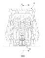
図1〜5に示されているように、本開示の挿入装置の第1の実施形態はホストに挿入する前の挿入ニードルの移動を案内して安定化させることができ、制限部材100と、作動ユニット200と、挿入モジュール30とを有している。
制限部材100は、上ケーシング10と、上ケーシング10に固く連結されることができる下ケーシング20と、を有している。As shown in FIGS. 1-5, the first embodiment of the insertion device of the present disclosure can guide and stabilize the movement of the insertion needle before insertion into the host, with the
The
作動モジュール200は、上ケーシング10内に配置されるカバーボディ12と、カバーボディ12内に収容されるメインカバー32と、メインカバー32に接続される挿入シート33と、メインカバー32と挿入シート33とに当接する第1の弾性部材34と、メインカバー32と挿入シート33との間に配置される引き抜きシート35と、引き抜きシート35と挿入シート33とに当接する第2の弾性部材37と、を有している。カバーボディ12はボトム部に一対のライニング係合構造124を有する。第1の弾性部材34と第2の弾性部材37は予め圧縮されたスプリングとして構成されることができる。カバーボディ12は内周面に一対の作動部123を有する。メインカバー32は挿入シート33へ延伸する制限部材323を有する。挿入シート33は一対の釣り針形の引き抜き位置決め部334と、カバーボディ12の作動部123によりそれぞれ押されることができる一対のバックル部335と、を有する。 The
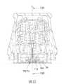
挿入モジュール30はホストに挿入する前の挿入ニードルの移動を案内して安定化させることができ、本体31と、補助挿入シート38と、挿入ニードルアセンブリ36と、ベース50と、センサアセンブリ70と、を有する。 The
本体31は、カバーボディ12のライニング係合構造124とそれぞれ係合できる1対の本体係合構造311と、軸線(L)に沿って延伸する収容ホール312と、収容ホール312に連通するように軸線(L)の周りに配置される複数のスライド溝313と、1対の阻止部314と、を有する。挿入シート33のバックル部335はそれぞれ個別に本体31の阻止部314に当接することにより挿入制限構造(A)(図4参照)を構成する。各スライド溝313は軸線(L)の周りに互いに等距離を開けて配置されている。この実施形態において、スライド溝313の数は3個である。各スライド溝313は、挿入方向(F)に沿って徐々に広がる壁面315(図4参照)を有する。各スライド溝313が有する壁面315は、軸線(L)と0°〜3°の角度をなす。 The
補助挿入シート38はベース部381と、ベース部381に接続する複数のウィング部382と、ベース部381の下面から突起する複数のカップリング突起部383と、を有する。ベース部381は収容ホール312に沿って移動することができる。各ウィング部382はそれぞれ1つのスライド溝313に沿って移動することができる。各ウィング部382は対応するスライド溝313の壁面315に点接触するよう弾性的に当接する突起部385を有する。各ウィング部382は2つのノッチ384を有すると共にH字形である。各ウィング部382のノッチ384がウィング部382のトップ部とボトム部にそれぞれ形成されていることにより、各ウィング部382は、補助挿入シート38の軸線(L)と直交する径方向に圧縮されると、径方向外側への復元力を提供するようになる。補助挿入シート38のウィング部382は軸線(L)の周りに互いに等距離を開けて配置されている。変化例において、ウィング部382の数は2個であることができ、そしてウィング部382は互いに均等的に180°離れることになる。 The
挿入ニードルアセンブリ36は、引き抜きシート35と補助挿入シート38のベース部381との間に設置されているニードルシート361と、ニードルシート361に接続される挿入ニードル362と、を有する。ニードルシート361と引き抜きシート35とは互いに離れることができ、これにより製造誤差による両者の間の配列ズレを防ぐことができる。図18に示されるように、挿入ニードル362の先端363とホストの皮膚表面との間の距離は初期ストローク距離(H)として定義される。この実施形態において、初期ストローク距離(H)は1ミリメートル以下である。 The
ベース50は取り外し可能に本体31のボトム部に配置されて、且つ、接着パッドにより皮膚表面に接着されることができる。 The
センサアセンブリ70はセンシングシート71と、センシングシート71内に保持されるセンサ72と、を有している。センシングシート71は、補助挿入シート38のカップリング突起部383を係合させるための複数のカップリング凹部711を有する。挿入ニードル362は、センシングシート71を挿通してセンサ72をカバーする。 The
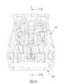
図3と図4に示されているように、該挿入装置の第1の実施形態が組立てられると、本体アセンブリ300の上部302と下部303は互いに接続され、カバーボディ12のトップ部とメインカバー32のトップ部は距離(D)を置いて互いに離れており(図3参照)、挿入シート33のバックル部335はそれぞれ本体31の阻止部314に当接して挿入シート33を挿入前位置に配置させ、第1の弾性部材34は挿入シート33とメインカバー32との間に予め圧縮されて復元力を生成し、第2の弾性部材37は引き抜きシート35と挿入シート33との間に予め圧縮されて復元力を生成し、挿入シート33の引き抜き位置決め部334はメインカバー32の制限部材323により制限されるため引き抜きシート35は挿入前位置に位置し、補助挿入シート38のカップリング突起部383はセンシングシート71のカップリング凹部711内にはめ込まれるためセンシングシート71と補助挿入シート38とは互いに接続され、補助挿入シート38は挿入ニードルアセンブリ36のニードルシート361に接続されるため挿入ニードルアセンブリ36は本体31内に保持されると共にベース50により遮蔽され、そしてベース50は本体31に相対的に位置決めされる。挿入シート33の引き抜き位置決め部334はメインカバーの制限部材323により移動可能に制限されるため、引き抜きシート35を挿入シート33に相対的に位置決めする引き抜き制限構造(B)(図4参照)を形成する。 As shown in FIGS. 3 and 4, when the first embodiment of the insertion device is assembled, the upper 302 and the lower 303 of the main body assembly 300 are connected to each other, and the top portion and the main cover of the
図6と図7に示されているように、ベース50はまずホストの皮膚表面の挿入予定箇所に配置される。上ケーシング10が押されていない時、挿入シート33のバックル部335と本体31の阻止部314との間に形成される挿入制限構造(A)が挿入シート33を挿入前位置に維持する。図8、図9に示されているように、上ケーシング10が皮膚表面に向かって押されると、挿入シート33の各バックル部335がそれぞれ上ケーシング10の各作動部123に押されて内側へ変形し、且つ、それぞれ本体31の阻止部314から離れるため挿入制限構造(A)は崩れる。これと同時に、本体31の各本体係合構造311はそれぞれカバーボディ12の各ライニング係合構造124に係合するため、上ケーシング10は本体31に相対的に位置決めされる。 As shown in FIGS. 6 and 7, the
図10、図11に示されるように、挿入制限構造(A)が崩れると、第1の弾性部材34の復元力が解放されて挿入シート33を挿入位置に移動して自動挿入を実行させることにより、センサアセンブリ70が挿入シート33によりポスト挿入位置に移動され、センサ72の一部分が皮膚表面の下に挿入され、そしてセンシングシート71がベース50のマウンティング部500の上に位置決めされる。センサ72が皮膚表面の下に挿入された後、メインカバー32の制限部材323は挿入シート33の引き抜き位置決め部334から離れるため、引き抜き位置決め部334は外側へ変形することができるようになり引き抜き制限構造(B)が崩れる。これにより第2の弾性部材37の復元力が解放され、引き抜きシート35を駆動して引き抜き方向(R)に移動させて挿入シート33の引き抜き位置決め部334を皮膚表面から離れさせるので、挿入ニードルアセンブリ36は補助挿入シート38から離れて挿入シート33内に引き抜かれて挿入ニードル362をそこに隠して自動引き抜きを実行させる(図12と図13参照)。補助挿入シート38のカップリング突起部383がセンシングシート71のカップリング凹部711内にはめ込まれたままなので、補助挿入シート38はセンサアセンブリ70のセンシングシート71に接続されている。センサアセンブリ70は挿入オペレーションの期間中にベース50内に位置させられており、そしてベース50は接着パッド52により皮膚表面に接着されている(図14、図15参照、ベース50はすでに本体31のボトム部から離れている)。 As shown in FIGS. 10 and 11, when the insertion limiting structure (A) collapses, the restoring force of the first
図16、図17に示されているように、挿入オペレーションが完了した後、分離された下ケーシング20は上ケーシング10に再度接続されることができ、これにより使用後の挿入装置は医療廃棄物のコンプライアンスに従って廃棄されることができる。 As shown in FIGS. 16 and 17, after the insertion operation is complete, the separated
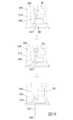
図3、図5、図18に示されているように、挿入の期間中に挿入ニードルアセンブリ36の初期スピードは挿入ニードル362が挿入方向(F)に平行することを確保することができない。この時、ウィング部382の突起部385とスライド溝313の壁面315との間の接触は、挿入ニードル362が挿入方向(F)に平行するように位置させる効果を発揮することができる。挿入ニードルアセンブリ36が真っ直ぐに挿入されるように且つ挿入方向(F)からずれないように加速されると、ウィング部382の突起部385はスライド溝313の挿入方向(F)に沿って徐々に広がる壁面315から離される。これにより、挿入ニードル362は初期ストローク距離(H)において安定に案内され、そして初期ストローク距離(H)の後に挿入ニードル362が皮膚表面に接触する際皮膚表面により支持されるので、安定且つ迅速的に皮膚表面の下へ挿入される。ウィング部382の各ノッチ384のおかげで、各ウィング部382は補助挿入シート38の径方向に圧縮されることができ、圧縮されると径方向外側への復元力を生成する。更に、ウィング部382の突起部385はスライド溝313の壁面315に当接して挿入ニードルアセンブリ36を位置決めするので、挿入ニードル362の挿入方向(F)からのずれを防ぐことができ、従って挿入ニードル362はホストに安定に挿入されることができるので、ホストの不快感を和らげることができる。 As shown in FIGS. 3, 5, and 18, the initial speed of the
図19に示されるように、本開示の挿入装置の第2の実施形態は、以下の点で第1の実施形態と相違する。即ち、補助挿入シート38’の各ウィング部382’は上側へ開口するノッチ384’を有する。各ウィング部382’のノッチ384’は該ウィング部382’のトップ部から下へ延伸しており、よって各ウィング部382’は軸線(L)と直交する補助挿入シート38’の径方向に圧縮されることができ、そして圧縮されると径方向外側への復元力を生成する。 As shown in FIG. 19, the second embodiment of the insertion device of the present disclosure differs from the first embodiment in the following points. That is, each wing portion 382'of the auxiliary insertion sheet 38' has a
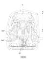
図20に示されるように、本開示の挿入装置の第3の実施形態は、以下の点で第1の実施形態と相違する。即ち、補助挿入シート38”の各ウィング部382”は下側へ開口するノッチ384”を有する。各ウィング部382”のノッチ384”は該ウィング部382”のボトム部から上へ延伸しており、よって各ウィング部382”は軸線(L)と直交する補助挿入シート38”の径方向に圧縮されることができ、そして圧縮されると径方向外側への復元力を生成する。 As shown in FIG. 20, the third embodiment of the insertion device of the present disclosure differs from the first embodiment in the following points. That is, each
上記をまとめると、挿入モジュール30の挿入ニードルアセンブリ36は補助挿入シート38に組み込まれ、且つ、ウィング部382の突起部385とスライド溝313の壁面315との接触により位置決められるので、初期ストローク距離(H)において挿入ニードル362は安定に案内され、そして挿入方向(F)から斜めになることが防止されてホストの不快感を和らげることができる。 Summarizing the above, the
上記においては、本発明の全体的な理解を促すべく、多くの具体的な詳細が示された。しかしながら、当業者であれば、一またはそれ以上の他の実施形態が具体的な詳細を示さなくとも実施され得ることが明らかである。また、本明細書における「一つの実施形態」「一実施形態」を示す説明において、序数などの表示を伴う説明は全て、特定の態様、構造、特徴を有する本発明の具体的な実施に含まれ得るものであることと理解されたい。さらに、本説明において、時には複数の変化例が一つの実施形態、図面、またはこれらの説明に組み込まれているが、これは本説明を合理化させるためのもので、また、本発明の多面性が理解されることを目的としたものであり、また、一実施形態における一またはそれ以上の特徴あるいは特定の具体例は、適切な場合には、本開示の実施において、他の実施形態における一またはそれ以上の特徴あるいは特定の具体例と共に実施され得る。 In the above, many specific details have been presented to facilitate an overall understanding of the invention. However, it will be apparent to those skilled in the art that one or more other embodiments may be implemented without specific details. In addition, in the description showing "one embodiment" and "one embodiment" in the present specification, all the explanations accompanied by the display such as ordinal numbers are included in the specific implementation of the present invention having a specific aspect, structure, and characteristics. Please understand that it is possible. Further, in the present description, sometimes a plurality of variations are incorporated into one embodiment, drawing, or description thereof, but this is for the purpose of rationalizing the present description, and the multifaceted nature of the present invention is present. It is intended to be understood, and one or more features or specific embodiments in one embodiment, where appropriate, in the practice of the present disclosure, are one or more in the other embodiments. It can be carried out with more features or specific examples.
以上、本発明の好ましい実施形態及び変化例を説明したが、本発明はこれらに限定されるものではなく、最も広い解釈の精神および範囲内に含まれる様々な構成として、全ての修飾および均等な構成を包含するものとする。 Although the preferred embodiments and variations of the present invention have been described above, the present invention is not limited thereto, and all modifications and equivalents are made as various configurations included in the spirit and scope of the broadest interpretation. It shall include the composition.
Claims (20)
Translated fromJapanese軸線(L)に沿って延伸する収容ホール(312)と、前記収容ホール(312)上に前記軸線(L)の周りに配置されて前記収容ホール(312)に連通する複数のスライド溝(313)とを有する本体(31)と、
ベース部(381)と、該ベース部(381)に接続され、それぞれ1つの前記スライド溝(313)内で往復移動可能であり、且つそれぞれ突起部(385)を有する複数のウィング部(382)とを有する補助挿入シート(38)と、
前記補助挿入シート(38)の前記ベース部(381)に組み込まれるニードルシート(361)と前記ニードルシート(361)に接続される挿入ニードル(362)とを有し、前記挿入ニードル(362)の先端(363)と前記ホストの皮膚表面との距離が初期ストローク距離(H)として定義されている挿入ニードルアセンブリ(36)と、
センシングシート(71)と前記センシングシート(71)内に保持されるセンサ(72)とを有し、前記センシングシート(71)は前記補助挿入シート(38)の前記ベース部(381)に組み込まれており、前記挿入ニードル(362)が前記センシングシート(71)を挿通して前記センサ(72)をカバーするセンサアセンブリ(70)と、を備え、
各前記スライド溝(313)は壁面(315)を有し、各前記ウィング部(382)の前記突起部(385)は対応する前記スライド溝(313)の前記壁面(315)に点接触するよう弾性的に当接することで、前記突起部(385)と前記壁面(315)との間の干渉によりホストに挿入する前の前記補助挿入シート(38)を固定して前記初期ストローク距離において前記挿入ニードル(362)が安定して挿入されるようにし且つ前記挿入ニードル(362)が斜めに成るのを防止する、挿入モジュール(30)。An insertion module (30) configured to guide and stabilize the movement of the insertion needle before it is inserted into the host.
An accommodation hole (312) extending along the axis (L) and a plurality of slide grooves (313) arranged around the axis (L) on the accommodation hole (312) and communicating with the accommodation hole (312). ) And the main body (31)
A plurality of wing portions (382) connected to the base portion (381) and reciprocating within one slide groove (313), each having a protrusion (385). Auxiliary insertion sheet (38) with
The insertion needle (362) has a needle sheet (361) incorporated in the base portion (381) of the auxiliary insertion sheet (38) and an insertion needle (362) connected to the needle sheet (361). An insertion needle assembly (36) in which the distance between the tip (363) and the skin surface of the host is defined as the initial stroke distance (H).
It has a sensing sheet (71) and a sensor (72) held in the sensing sheet (71), and the sensing sheet (71) is incorporated in the base portion (381) of the auxiliary insertion sheet (38). The insertion needle (362) comprises a sensor assembly (70) through which the sensing sheet (71) is inserted to cover the sensor (72).
Each slide groove (313) has a wall surface (315) so that the protrusion (385) of each wing portion (382) makes point contact with the wall surface (315) of the corresponding slide groove (313). By elastically abutting, the auxiliary insertion sheet (38) before being inserted into the host due to interference between the protrusion (385) and the wall surface (315) is fixed and the insertion is performed at the initial stroke distance. An insertion module (30) that ensures stable insertion of the needle (362) and prevents the insertion needle (362) from being slanted.
前記作動モジュール(200)は、カバーボディ(12)と、前記カバーボディ(12)内に収容されているメインカバー(32)と、前記メインカバー(32)に接続されている挿入シート(33)と、前記メインカバー(32)と前記挿入シート(33)に当接する第1の弾性部材(34)と、前記メインカバー(32)と前記挿入シート(33)との間に配置される引き抜きシート(35)と、前記引き抜きシート(35)と前記挿入シート(33)に当接する第2の弾性部材(37)と、を有しており、
前記挿入モジュール(30)は、
軸線(L)に沿って延伸する収容ホール(312)と、前記収容ホール(312)上に前記軸線(L)の周りに配置されて前記収容ホール(312)に連通する複数のスライド溝(313)とを有する本体(31)と、
ベース部(381)と、該ベース部(381)に接続され、それぞれ1つの前記スライド溝(313)内で往復移動可能であり、且つそれぞれ突起部(385)を有する複数のウィング部(382)とを有する補助挿入シート(38)と、
前記補助挿入シート(38)の前記ベース部(381)に組み込まれるニードルシート(361)と前記ニードルシート(361)に接続される挿入ニードル(362)とを有し、前記挿入ニードル(362)の先端(363)とホストの皮膚表面との距離が初期ストローク距離(H)として定義されている挿入ニードルアセンブリ(36)と、
センシングシート(71)と前記センシングシート(71)内に保持されるセンサ(72)とを有し、前記センシングシート(71)は前記補助挿入シート(38)の前記ベース部(381)に組み込まれており、前記挿入ニードル(362)が前記センシングシート(71)を挿通して前記センサ(72)をカバーするセンサアセンブリ(70)と、を有し、
各前記スライド溝(313)は壁面(315)を有し、各前記ウィング部(382)の前記突起部(385)は対応する前記スライド溝(313)の前記壁面(315)に点接触するよう弾性的に当接することで、前記突起部(385)と前記壁面(315)との間の干渉によりホストに挿入する前の前記補助挿入シート(38)が固定されて前記初期ストローク距離において前記挿入ニードル(362)が安定して挿入されるようにし且つ前記挿入ニードル(362)が斜めに成るのを防止する、挿入装置。An insertion device including an actuating module (200) and an insertion module (30).
The actuating module (200) includes a cover body (12), a main cover (32) housed in the cover body (12), and an insertion sheet (33) connected to the main cover (32). And a first elastic member (34) that comes into contact with the main cover (32) and the insertion sheet (33), and a pull-out sheet arranged between the main cover (32) and the insertion sheet (33). It has (35), and a second elastic member (37) that comes into contact with the pull-out sheet (35) and the insertion sheet (33).
The insertion module (30) is
An accommodation hole (312) extending along the axis (L) and a plurality of slide grooves (313) arranged around the axis (L) on the accommodation hole (312) and communicating with the accommodation hole (312). ) And the main body (31)
A plurality of wing portions (382) connected to the base portion (381) and reciprocating within one slide groove (313), each having a protrusion (385). Auxiliary insertion sheet (38) with
The insertion needle (362) has a needle sheet (361) incorporated in the base portion (381) of the auxiliary insertion sheet (38) and an insertion needle (362) connected to the needle sheet (361). With the insertion needle assembly (36), where the distance between the tip (363) and the skin surface of the host is defined as the initial stroke distance (H),
It has a sensing sheet (71) and a sensor (72) held in the sensing sheet (71), and the sensing sheet (71) is incorporated in the base portion (381) of the auxiliary insertion sheet (38). The insertion needle (362) has a sensor assembly (70) through which the sensing sheet (71) is inserted and covers the sensor (72).
Each slide groove (313) has a wall surface (315) so that the protrusion (385) of each wing portion (382) makes point contact with the wall surface (315) of the corresponding slide groove (313). By elastically abutting, the auxiliary insertion sheet (38) before being inserted into the host is fixed by the interference between the protrusion (385) and the wall surface (315), and the insertion is performed at the initial stroke distance. An insertion device that ensures stable insertion of the needle (362) and prevents the insertion needle (362) from being slanted.
The insertion device according to claim 11, wherein the initial stroke distance (H) is 1 mm or less.
Applications Claiming Priority (2)
| Application Number | Priority Date | Filing Date | Title |
|---|---|---|---|
| US201962882140P | 2019-08-02 | 2019-08-02 | |
| US62/882,140 | 2019-08-02 |
Publications (2)
| Publication Number | Publication Date |
|---|---|
| JP2021041144A JP2021041144A (en) | 2021-03-18 |
| JP6986603B2true JP6986603B2 (en) | 2021-12-22 |
Family
ID=71899622
Family Applications (3)
| Application Number | Title | Priority Date | Filing Date |
|---|---|---|---|
| JP2020131738AActiveJP6986603B2 (en) | 2019-08-02 | 2020-08-03 | Insertion module and insertion device with it |
| JP2020131795AActiveJP7134201B2 (en) | 2019-08-02 | 2020-08-03 | physiological signal monitoring device |
| JP2020131916AActiveJP7077370B2 (en) | 2019-08-02 | 2020-08-03 | Physiological signal monitoring device and its sensor holder |
Family Applications After (2)
| Application Number | Title | Priority Date | Filing Date |
|---|---|---|---|
| JP2020131795AActiveJP7134201B2 (en) | 2019-08-02 | 2020-08-03 | physiological signal monitoring device |
| JP2020131916AActiveJP7077370B2 (en) | 2019-08-02 | 2020-08-03 | Physiological signal monitoring device and its sensor holder |
Country Status (10)
| Country | Link |
|---|---|
| US (7) | US11504032B2 (en) |
| EP (7) | EP3771409B1 (en) |
| JP (3) | JP6986603B2 (en) |
| KR (2) | KR102449247B1 (en) |
| CN (22) | CN112294301B (en) |
| AU (2) | AU2020294300B2 (en) |
| CA (2) | CA3104329A1 (en) |
| DE (1) | DE202020104460U1 (en) |
| TW (26) | TWI723733B (en) |
| WO (2) | WO2021023148A1 (en) |
Families Citing this family (37)
| Publication number | Priority date | Publication date | Assignee | Title |
|---|---|---|---|---|
| US9788771B2 (en) | 2006-10-23 | 2017-10-17 | Abbott Diabetes Care Inc. | Variable speed sensor insertion devices and methods of use |
| US11071478B2 (en) | 2017-01-23 | 2021-07-27 | Abbott Diabetes Care Inc. | Systems, devices and methods for analyte sensor insertion |
| CN112423664B (en) | 2018-06-07 | 2025-01-21 | 雅培糖尿病护理公司 | Focused sterilization and sterilized sub-assemblies for analyte monitoring systems |
| CA3230184A1 (en)* | 2019-08-02 | 2021-02-02 | Bionime Corporation | Physiological signal monitoring device |
| CN112294301B (en)* | 2019-08-02 | 2024-12-31 | 华广生技股份有限公司 | Physiological signal sensor device |
| EP4017357A4 (en)* | 2019-08-19 | 2023-04-19 | Medtrum Technologies Inc. | MEASURING DEVICE |
| CA3188510A1 (en) | 2020-08-31 | 2022-03-03 | Vivek S. RAO | Systems, devices, and methods for analyte sensor insertion |
| AU2021344214A1 (en)* | 2020-09-15 | 2023-03-23 | Abbott Diabetes Care Inc. | Systems, devices, and methods for analyte monitoring |
| US11852643B2 (en)* | 2020-10-13 | 2023-12-26 | Bionime Corporation | Physiological signal monitoring device |
| TWI793800B (en)* | 2020-10-14 | 2023-02-21 | 華廣生技股份有限公司 | Insertion needle structure and inserter |
| TWI849296B (en)* | 2021-01-08 | 2024-07-21 | 華廣生技股份有限公司 | Patch and method for using a patch |
| EP4346587A4 (en)* | 2021-05-31 | 2024-10-30 | Medtrum Technologies Inc. | ANALYTE DETECTION DEVICE INTEGRATED INTO A BATTERY ENCLOSURE |
| CN113499127B (en)* | 2021-06-28 | 2024-03-01 | 苏州百孝医疗科技有限公司 | Fixing structure of sensor base and method for removing sensor base |
| KR102592776B1 (en)* | 2021-06-29 | 2023-10-25 | 주식회사 아이센스 | Needle for transcutaneous sensor insertion and needle assembly having the same |
| CN115704820B (en)* | 2021-08-06 | 2025-08-05 | 上海移宇科技股份有限公司 | Body fluid analyte detection devices |
| CN115868974B (en)* | 2021-09-29 | 2025-09-09 | 上海微创生命科技有限公司 | Medical equipment and medical auxiliary device |
| CN116172549B (en)* | 2021-11-26 | 2025-08-12 | 上海微创生命科技有限公司 | medical devices |
| CN116195994A (en)* | 2021-11-30 | 2023-06-02 | 上海微创生命科技有限公司 | Sterilization box assembly, implanter and implantation system |
| CN114642426A (en)* | 2022-03-02 | 2022-06-21 | 苏州百孝医疗科技有限公司 | Method for manufacturing electronic device and electronic device |
| CN114831633B (en)* | 2022-04-29 | 2025-07-25 | 天津九安医疗电子股份有限公司 | Sensor implantation device |
| CN115089274A (en)* | 2022-05-26 | 2022-09-23 | 浙江康德莱医疗器械股份有限公司 | A puncture guide needle |
| WO2024028507A1 (en)* | 2022-08-05 | 2024-02-08 | Unomedical A/S | Inserter assembly and method |
| WO2024028506A1 (en)* | 2022-08-05 | 2024-02-08 | Unomedical A/S | Anchor assembly |
| TWD226583S (en)* | 2022-08-31 | 2023-07-21 | 華廣生技股份有限公司 | Physiological signal monitoring patch |
| TWD226584S (en)* | 2022-08-31 | 2023-07-21 | 華廣生技股份有限公司 | Physiological signal monitoring patch |
| TWD226582S (en)* | 2022-08-31 | 2023-07-21 | 華廣生技股份有限公司 | Physiological signal monitoring patch |
| TWI806771B (en)* | 2022-09-16 | 2023-06-21 | 英業達股份有限公司 | Anti-static electricity type electronic device |
| CN116058937A (en)* | 2022-10-11 | 2023-05-05 | 深圳可孚生物科技有限公司 | A biosensor-assisted implantation device |
| WO2024080457A1 (en)* | 2022-10-14 | 2024-04-18 | 국민대학교산학협력단 | Scalable implantable biosensor device |
| CN115399757B (en)* | 2022-10-31 | 2023-01-24 | 深圳刷新生物传感科技有限公司 | High-reliability implantation device of implantable biosensor |
| USD1095842S1 (en)* | 2023-02-10 | 2025-09-30 | I-Sens, Inc. | Continuous blood glucose measurement sensor |
| US20240298929A1 (en)* | 2023-03-08 | 2024-09-12 | Medtronic Minimed, Inc. | Substrate sealing configurations and methods |
| TWD231831S (en)* | 2023-03-15 | 2024-06-21 | 華廣生技股份有限公司 臺中市南區大慶街2段100號 (中華民國) | Part of a splitter for a physiological monitoring device |
| CN116626132A (en)* | 2023-05-15 | 2023-08-22 | 广州达安基因股份有限公司 | Implantable biosensor and preparation method thereof |
| CN116548963B (en)* | 2023-07-07 | 2023-09-05 | 苏州百孝医疗科技有限公司 | Percutaneous analyte continuous detection system and method of installing same |
| EP4534008A1 (en)* | 2023-08-21 | 2025-04-09 | Shanghai United Imaging Microelectronics Technology Co., Ltd. | Analyte sensor |
| WO2025162779A1 (en)* | 2024-01-31 | 2025-08-07 | Roche Diabetes Care Gmbh | Continuous analyte monitoring device |
Family Cites Families (256)
| Publication number | Priority date | Publication date | Assignee | Title |
|---|---|---|---|---|
| US3102539A (en)* | 1960-11-23 | 1963-09-03 | Graham Chemical Corp | Disposable cartridge type hypodermic syringe devices |
| EP0221005A3 (en)* | 1985-09-07 | 1987-12-02 | Wagner, Wolfgang, Dr.med. | Injection device with sensor |
| US5165407A (en)* | 1990-04-19 | 1992-11-24 | The University Of Kansas | Implantable glucose sensor |
| US5299571A (en)* | 1993-01-22 | 1994-04-05 | Eli Lilly And Company | Apparatus and method for implantation of sensors |
| JP2947064B2 (en)* | 1994-05-18 | 1999-09-13 | 住友電装株式会社 | connector |
| CN1174713C (en)* | 1995-08-29 | 2004-11-10 | 光谱股份有限公司 | Microporation method of human skin for drug delivery and monitoring applications |
| US6013058A (en)* | 1996-06-12 | 2000-01-11 | Biolink Corporation | Device for subcutaneous accessibility |
| US7899511B2 (en)* | 2004-07-13 | 2011-03-01 | Dexcom, Inc. | Low oxygen in vivo analyte sensor |
| US7657297B2 (en)* | 2004-05-03 | 2010-02-02 | Dexcom, Inc. | Implantable analyte sensor |
| JPH10253654A (en)* | 1997-03-11 | 1998-09-25 | Fujitsu Ten Ltd | Acceleration sensor packaging structure |
| KR20010013962A (en)* | 1997-06-20 | 2001-02-26 | 에프.지.엠. 헤르만스 ; 이.에이치. 리링크 | Preloaded implantation device |
| US6516808B2 (en)* | 1997-09-12 | 2003-02-11 | Alfred E. Mann Foundation For Scientific Research | Hermetic feedthrough for an implantable device |
| US5967986A (en)* | 1997-11-25 | 1999-10-19 | Vascusense, Inc. | Endoluminal implant with fluid flow sensing capability |
| US8465425B2 (en)* | 1998-04-30 | 2013-06-18 | Abbott Diabetes Care Inc. | Analyte monitoring device and methods of use |
| US8346337B2 (en)* | 1998-04-30 | 2013-01-01 | Abbott Diabetes Care Inc. | Analyte monitoring device and methods of use |
| GB2337118A (en)* | 1998-05-06 | 1999-11-10 | Csi Technology Inc | Interchangeable sensor monitoring device |
| AU1889001A (en)* | 1999-12-13 | 2001-06-18 | Arkray, Inc. | Body fluid measuring apparatus with lancet and lancet holder used for the measuring apparatus |
| US7393344B2 (en)* | 1999-12-23 | 2008-07-01 | Owais Mohammed | Hypodermic syringe needle assembly and method of making the same |
| DE60015721T2 (en)* | 2000-03-21 | 2005-03-31 | Radi Medical Systems Ab | Passive biotelemetry |
| JP4700209B2 (en)* | 2000-03-21 | 2011-06-15 | ラディ・メディカル・システムズ・アクチェボラーグ | Passive biotelemetry |
| US7006858B2 (en)* | 2000-05-15 | 2006-02-28 | Silver James H | Implantable, retrievable sensors and immunosensors |
| US7181261B2 (en)* | 2000-05-15 | 2007-02-20 | Silver James H | Implantable, retrievable, thrombus minimizing sensors |
| US6589229B1 (en)* | 2000-07-31 | 2003-07-08 | Becton, Dickinson And Company | Wearable, self-contained drug infusion device |
| US8454552B2 (en)* | 2000-08-24 | 2013-06-04 | Cardiac Science Corporation | Method for constructing an instrument with a covered bore for subcutaneous implantation |
| US8348882B2 (en)* | 2000-08-24 | 2013-01-08 | Cardiac Science Corporation | Instrument with a covered bore for subcutaneous implantation |
| US7736330B2 (en)* | 2000-08-24 | 2010-06-15 | Bardy Gust H | Subcutaneous implantation instrument with dissecting tool and method of construction |
| GB0025147D0 (en)* | 2000-10-13 | 2000-11-29 | Torsana Diabetes Diagnostics A | Optical sensor for in situ measurement of analytes |
| US6560471B1 (en)* | 2001-01-02 | 2003-05-06 | Therasense, Inc. | Analyte monitoring device and methods of use |
| EP1381408A4 (en) | 2001-02-22 | 2007-06-13 | Insulet Corp | Modular infusion device and method |
| WO2003088851A1 (en)* | 2001-06-12 | 2003-10-30 | Pelikan Technologies, Inc. | Tissue penetration device |
| GB0116853D0 (en)* | 2001-07-10 | 2001-09-05 | Torsana Diabetes Diagnostics A | Optical sensor containing particles for in SITU measurement of analytes |
| US7025760B2 (en)* | 2001-09-07 | 2006-04-11 | Medtronic Minimed, Inc. | Method and system for non-vascular sensor implantation |
| US8506550B2 (en)* | 2001-09-07 | 2013-08-13 | Medtronic Minimed, Inc. | Method and system for non-vascular sensor implantation |
| WO2003034902A2 (en)* | 2001-10-23 | 2003-05-01 | Medtronic Minimed Inc. | Method and system for non-vascular sensor implantation |
| US9492111B2 (en)* | 2002-04-22 | 2016-11-15 | Medtronic Minimed, Inc. | Methods and materials for stabilizing analyte sensors |
| US7020508B2 (en)* | 2002-08-22 | 2006-03-28 | Bodymedia, Inc. | Apparatus for detecting human physiological and contextual information |
| US7070591B2 (en)* | 2002-09-17 | 2006-07-04 | Transoma Medical, Inc. | Vascular access port with physiological sensor |
| US7736309B2 (en)* | 2002-09-27 | 2010-06-15 | Medtronic Minimed, Inc. | Implantable sensor method and system |
| US7381184B2 (en)* | 2002-11-05 | 2008-06-03 | Abbott Diabetes Care Inc. | Sensor inserter assembly |
| CN2585624Y (en)* | 2002-12-03 | 2003-11-12 | 名世电子企业股份有限公司 | pulse meter transmitter |
| US20070208245A1 (en)* | 2003-08-01 | 2007-09-06 | Brauker James H | Transcutaneous analyte sensor |
| US7519408B2 (en)* | 2003-11-19 | 2009-04-14 | Dexcom, Inc. | Integrated receiver for continuous analyte sensor |
| US7699807B2 (en)* | 2003-11-10 | 2010-04-20 | Smiths Medical Asd, Inc. | Device and method for insertion of a cannula of an infusion device |
| US7309326B2 (en)* | 2003-11-18 | 2007-12-18 | Icu Medical, Inc. | Infusion set |
| WO2005092177A1 (en)* | 2004-03-22 | 2005-10-06 | Bodymedia, Inc. | Non-invasive temperature monitoring device |
| US20070135697A1 (en)* | 2004-04-19 | 2007-06-14 | Therasense, Inc. | Method and apparatus for providing sensor guard for data monitoring and detection systems |
| US8792955B2 (en)* | 2004-05-03 | 2014-07-29 | Dexcom, Inc. | Transcutaneous analyte sensor |
| US8452368B2 (en)* | 2004-07-13 | 2013-05-28 | Dexcom, Inc. | Transcutaneous analyte sensor |
| JP4870075B2 (en)* | 2004-07-13 | 2012-02-08 | デックスコム・インコーポレーテッド | Transcutaneous analyte sensor |
| US8565848B2 (en)* | 2004-07-13 | 2013-10-22 | Dexcom, Inc. | Transcutaneous analyte sensor |
| US7783333B2 (en)* | 2004-07-13 | 2010-08-24 | Dexcom, Inc. | Transcutaneous medical device with variable stiffness |
| US7654956B2 (en)* | 2004-07-13 | 2010-02-02 | Dexcom, Inc. | Transcutaneous analyte sensor |
| TWM269870U (en)* | 2004-10-01 | 2005-07-11 | Taiject Medical Device Co Ltd | Easy assembling and operating blood collector |
| US9788771B2 (en)* | 2006-10-23 | 2017-10-17 | Abbott Diabetes Care Inc. | Variable speed sensor insertion devices and methods of use |
| CN101107025A (en)* | 2005-01-17 | 2008-01-16 | 诺和诺德公司 | Fluid delivery device with integrated monitoring of physiological characteristics |
| US7285846B1 (en)* | 2005-02-22 | 2007-10-23 | Littelfuse, Inc. | Integrated circuit package with ESD protection |
| JP2006334155A (en)* | 2005-06-02 | 2006-12-14 | Terumo Corp | Blood component measuring apparatus and chip for measuring blood component |
| WO2007003431A1 (en)* | 2005-07-06 | 2007-01-11 | Medizinische Universität Graz | Device for and method of delivery and removal of substances in and from a tissue or vessel |
| US9072476B2 (en)* | 2005-09-23 | 2015-07-07 | Medtronic Minimed, Inc. | Flexible sensor apparatus |
| US8123705B2 (en)* | 2005-10-06 | 2012-02-28 | Boston Scientific Scimed, Inc. | Adjustable profile probe |
| US20070173706A1 (en)* | 2005-11-11 | 2007-07-26 | Isense Corporation | Method and apparatus for insertion of a sensor |
| US9615851B2 (en)* | 2005-11-11 | 2017-04-11 | Waveform Technologies, Inc. | Method and apparatus for insertion of a sensor |
| US9757061B2 (en)* | 2006-01-17 | 2017-09-12 | Dexcom, Inc. | Low oxygen in vivo analyte sensor |
| JP4802737B2 (en)* | 2006-01-31 | 2011-10-26 | パナソニック株式会社 | Chemical solution administration device and control method thereof |
| EP3165247B1 (en)* | 2006-02-09 | 2020-10-28 | DEKA Products Limited Partnership | Pumping fluid delivery systems and methods using force application assembley |
| ES2871822T3 (en)* | 2006-02-22 | 2021-11-02 | Dexcom Inc | Analyte sensor |
| US20090131778A1 (en)* | 2006-03-28 | 2009-05-21 | Jina Arvind N | Devices, systems, methods and tools for continuous glucose monitoring |
| US20090012372A1 (en)* | 2006-06-12 | 2009-01-08 | Novalert, Inc. | External sensing for implant rupture |
| US8583224B2 (en)* | 2006-09-08 | 2013-11-12 | Cardiac Pacemakers, Inc. | Implantable medical device and methods for automated detection of infection |
| EP2079358B1 (en)* | 2006-09-27 | 2011-08-10 | University of Connecticut | Implantable biosensor and methods of use thereof |
| US20080091089A1 (en)* | 2006-10-12 | 2008-04-17 | Kenneth Shane Guillory | Single use, self-contained surface physiological monitor |
| US8214007B2 (en)* | 2006-11-01 | 2012-07-03 | Welch Allyn, Inc. | Body worn physiological sensor device having a disposable electrode module |
| TWM314590U (en)* | 2006-12-11 | 2007-07-01 | Health & Life Co Ltd | Physical detector having water-proof structure |
| WO2008105768A1 (en)* | 2007-03-01 | 2008-09-04 | Dexcom, Inc. | Analyte sensor |
| EP1972267A1 (en)* | 2007-03-20 | 2008-09-24 | Roche Diagnostics GmbH | System for in vivo measurement of an analyte concentration |
| JP5429586B2 (en)* | 2007-03-30 | 2014-02-26 | 株式会社タニタ | Blood glucose state estimation method and apparatus |
| CA2680841A1 (en)* | 2007-04-04 | 2008-10-16 | Isense Corporation | Analyte sensing device having one or more sensing electrodes |
| US20130144144A1 (en)* | 2007-04-19 | 2013-06-06 | C.G.M.3 Ltd. | Device system and method for monitoring and controlling blood analyte levels |
| JP5546243B2 (en)* | 2007-07-18 | 2014-07-09 | パナソニックヘルスケア株式会社 | Blood test equipment |
| JP2009028062A (en)* | 2007-07-24 | 2009-02-12 | Sumitomo Electric Ind Ltd | Blood collector for biosensor and sensor chip measuring device |
| US20090043183A1 (en)* | 2007-08-08 | 2009-02-12 | Lifescan, Inc. | Integrated stent and blood analyte monitoring system |
| GB0716427D0 (en)* | 2007-08-23 | 2007-10-03 | Smartsensor Telemed Ltd | Glucose tolerance test device |
| US20090105634A1 (en)* | 2007-10-17 | 2009-04-23 | Alza Corporation | Anodic Reservoir for Electrotransport of Cationic Drug |
| AU2009219678A1 (en)* | 2008-02-27 | 2009-09-03 | Mon4D Ltd. | Device, system and method for modular analyte monitoring |
| ITTO20080143A1 (en)* | 2008-02-28 | 2009-08-29 | Amc Instruments S R L | DEVICE FOR MONITORING MULTIFUNE SYSTEMS |
| US9295786B2 (en)* | 2008-05-28 | 2016-03-29 | Medtronic Minimed, Inc. | Needle protective device for subcutaneous sensors |
| TWI354548B (en)* | 2008-07-18 | 2011-12-21 | Bionime Corp | Adjustable assembly of lancet device |
| ES2530450T3 (en)* | 2008-10-02 | 2015-03-03 | Eyesense Ag | Implantable sensor element |
| TWI503101B (en)* | 2008-12-15 | 2015-10-11 | Proteus Digital Health Inc | Body-associated receiver and method |
| US9402544B2 (en)* | 2009-02-03 | 2016-08-02 | Abbott Diabetes Care Inc. | Analyte sensor and apparatus for insertion of the sensor |
| US20100256524A1 (en)* | 2009-03-02 | 2010-10-07 | Seventh Sense Biosystems, Inc. | Techniques and devices associated with blood sampling |
| TWI413770B (en)* | 2009-04-24 | 2013-11-01 | Univ Nat Taiwan | Wireless biomedical monitoring system |
| EP2266458A1 (en)* | 2009-06-23 | 2010-12-29 | Roche Diagnostics GmbH | Sensor for in-vivo measurements |
| US8996089B2 (en)* | 2009-06-30 | 2015-03-31 | Arkray, Inc. | Continuous analysis device and sample component control system |
| DK3689237T3 (en)* | 2009-07-23 | 2021-08-16 | Abbott Diabetes Care Inc | Method of preparation and system for continuous analyte measurement |
| KR20120047896A (en)* | 2009-08-07 | 2012-05-14 | 우노메디컬 에이/에스 | Delivery device with sensor and one or more cannulas |
| TWI481383B (en)* | 2009-09-25 | 2015-04-21 | Univ Nat Chiao Tung | Biosensor and electrode structure thereof |
| EP2482724A2 (en) | 2009-09-30 | 2012-08-08 | Dexcom, Inc. | Transcutaneous analyte sensor |
| WO2011053788A2 (en)* | 2009-10-30 | 2011-05-05 | Seventh Sense Biosystems, Inc. | Relatively small devices applied to the skin, modular systems, and methods of use thereof |
| US10918298B2 (en)* | 2009-12-16 | 2021-02-16 | The Board Of Trustees Of The University Of Illinois | High-speed, high-resolution electrophysiology in-vivo using conformal electronics |
| EP2335565A1 (en)* | 2009-12-18 | 2011-06-22 | Roche Diagnostics GmbH | Protective container for holding reusable diagnostic components |
| WO2011088211A2 (en)* | 2010-01-13 | 2011-07-21 | Seventh Sense Biosystems, Inc. | Sampling device interfaces |
| WO2011112931A1 (en)* | 2010-03-12 | 2011-09-15 | The Board Of Trustees Of The University Of Illinois | Waterproof stretchable optoelectronics |
| US10448872B2 (en)* | 2010-03-16 | 2019-10-22 | Medtronic Minimed, Inc. | Analyte sensor apparatuses having improved electrode configurations and methods for making and using them |
| AU2011230596A1 (en)* | 2010-03-24 | 2012-01-19 | Abbott Diabetes Care Inc. | Medical device inserters and processes of inserting and using medical devices |
| LT3622883T (en)* | 2010-03-24 | 2021-08-25 | Abbott Diabetes Care, Inc. | Medical device inserters and processes of inserting and using medical devices |
| JP2011204483A (en)* | 2010-03-25 | 2011-10-13 | Denso Corp | Electrical connector and circuit board mounted with the same |
| KR20130018783A (en)* | 2010-03-30 | 2013-02-25 | 우노메디컬 에이/에스 | Medical device |
| JP2012026910A (en)* | 2010-07-26 | 2012-02-09 | Arkray Inc | Biosensor unit and biosensor system |
| TWI439689B (en)* | 2010-09-23 | 2014-06-01 | Bionime Corp | Electrochemical test specimen |
| DK2621339T3 (en)* | 2010-09-29 | 2020-02-24 | Dexcom Inc | ADVANCED SYSTEM FOR CONTINUOUS ANALYTICAL MONITORING |
| WO2012068393A1 (en)* | 2010-11-18 | 2012-05-24 | Abbott Diabetes Care Inc. | Adaptor for on-body analyte monitoring system |
| CN107961016B (en)* | 2010-12-09 | 2021-06-15 | 雅培糖尿病护理股份有限公司 | Analyte sensor having a sensing surface comprising a small sensing spot |
| WO2012097879A1 (en)* | 2011-01-21 | 2012-07-26 | St. Jude Medical Ab | Implantable device with improved surface characteristics |
| US8424388B2 (en)* | 2011-01-28 | 2013-04-23 | Medtronic, Inc. | Implantable capacitive pressure sensor apparatus and methods regarding same |
| CN102613978B (en)* | 2011-01-31 | 2014-12-03 | 厚美德生物科技股份有限公司 | Test strip |
| US9649113B2 (en)* | 2011-04-27 | 2017-05-16 | Covidien Lp | Device for monitoring physiological parameters in vivo |
| TWI569773B (en)* | 2011-05-26 | 2017-02-11 | 華廣生技股份有限公司 | System and method of measuring a physiological parameter therein |
| EP2720610B1 (en) | 2011-06-17 | 2025-07-16 | Abbott Diabetes Care Inc. | Stacked analyte sensor having a first electrode narrower than a second electrode of the sensor |
| US10638955B2 (en)* | 2011-06-30 | 2020-05-05 | Endotronix, Inc. | Pressure sensing implant |
| KR20140082642A (en)* | 2011-07-26 | 2014-07-02 | 글리젠스 인코포레이티드 | Tissue implantable sensor with hermetically sealed housing |
| JP6090795B2 (en)* | 2011-09-09 | 2017-03-08 | テルモ株式会社 | Sensor insertion device |
| WO2013038691A1 (en)* | 2011-09-14 | 2013-03-21 | パナソニック株式会社 | Biological information detection sensor supply device |
| TWI452997B (en)* | 2011-10-05 | 2014-09-21 | Univ Kun Shan | Biosensor chip with nano-structures |
| EP2586479A1 (en)* | 2011-10-31 | 2013-05-01 | Sanofi-Aventis Deutschland GmbH | Safety needle assembly |
| EP2713879B1 (en)* | 2011-12-11 | 2017-07-26 | Abbott Diabetes Care, Inc. | Analyte sensor devices, connections, and methods |
| WO2013105508A1 (en)* | 2012-01-13 | 2013-07-18 | パナソニック株式会社 | Biological information measurement apparatus |
| TWI477256B (en)* | 2012-01-19 | 2015-03-21 | Bionime Corp | Lancing device |
| US9931065B2 (en)* | 2012-04-04 | 2018-04-03 | Dexcom, Inc. | Transcutaneous analyte sensors, applicators therefor, and associated methods |
| US9883834B2 (en)* | 2012-04-16 | 2018-02-06 | Farid Amirouche | Medication delivery device with multi-reservoir cartridge system and related methods of use |
| US20130289522A1 (en)* | 2012-04-24 | 2013-10-31 | The Royal Institution For The Advancement Of Learning / Mcgill University | Methods and Systems for Closed Loop Neurotrophic Delivery Microsystems |
| US9493807B2 (en)* | 2012-05-25 | 2016-11-15 | Medtronic Minimed, Inc. | Foldover sensors and methods for making and using them |
| US9119449B2 (en)* | 2012-07-20 | 2015-09-01 | Panasonic Healthcare Holdings Co., Ltd. | Biological information measurement device and protective cover |
| US10660550B2 (en)* | 2015-12-29 | 2020-05-26 | Glysens Incorporated | Implantable sensor apparatus and methods |
| EP2698686B1 (en)* | 2012-07-27 | 2018-10-10 | LG Electronics Inc. | Wrist-wearable terminal and control method thereof |
| DE102012107835A1 (en)* | 2012-08-24 | 2014-02-27 | Albert-Ludwigs-Universität Freiburg | Medical implant and method for its production |
| US20140066884A1 (en)* | 2012-08-30 | 2014-03-06 | Medtronic Minimed, Inc. | Sensor model supervisor for a closed-loop insulin infusion system |
| WO2014045447A1 (en)* | 2012-09-24 | 2014-03-27 | テルモ株式会社 | Sensor insertion device and sensor insertion method |
| JP2015534495A (en)* | 2012-10-12 | 2015-12-03 | デルタ、ダンスク・エレクトリニク、リス・オ・アクスティクDelta,Dansk Elektronik,Lys Og Akustik | Monitoring device |
| TWI586318B (en)* | 2012-10-16 | 2017-06-11 | 長庚大學 | Integrated biological information sensing device |
| EP2925229A4 (en)* | 2012-12-03 | 2017-01-25 | Pepex Biomedical, Inc. | Sensor module and method of using a sensor module |
| US20150352229A1 (en)* | 2012-12-28 | 2015-12-10 | Glusense, Ltd. | Apparatus for facilitating cell growth in an implantable sensor |
| US20140324067A1 (en)* | 2013-01-09 | 2014-10-30 | Senseonics, Incorporated | Subcutaneous tunneling and implantation tools for a disk-shaped sensor |
| EP2953542A4 (en)* | 2013-02-06 | 2016-10-05 | California Inst Of Techn | IMPLANTABLE AND MINIATURIZED ELECTROCHEMICAL SENSOR DEVICES |
| JP2014173917A (en)* | 2013-03-07 | 2014-09-22 | Seiko Epson Corp | Sensor, electronic apparatus, and moving body |
| NZ712147A (en)* | 2013-03-15 | 2018-04-27 | Janssen Biotech Inc | Palm activated drug delivery device |
| TW201515637A (en)* | 2013-10-24 | 2015-05-01 | Ysp Co Ltd | Disposable blood collecting lancet structure |
| CN203644304U (en)* | 2013-10-28 | 2014-06-11 | 深圳市航天华拓科技有限公司 | Anti-dismount tag |
| CA3205443A1 (en)* | 2013-11-07 | 2015-05-14 | Dexcom, Inc. | Systems and methods for transmitting and continuous monitoring of analyte values |
| WO2015084269A1 (en)* | 2013-12-05 | 2015-06-11 | Dexing Pang | Implantable biosensor |
| CN104887242B (en)* | 2014-03-07 | 2018-08-28 | 上海移宇科技股份有限公司 | Analyte sensing system |
| US10791984B2 (en)* | 2014-03-12 | 2020-10-06 | Viaderm, Llc. | Active hermeticity monitoring |
| US20170281038A1 (en)* | 2014-03-12 | 2017-10-05 | Zansors, Llc | Wireless ecg acquisition and monitoring device and system |
| WO2015138964A1 (en)* | 2014-03-13 | 2015-09-17 | Hadar Liron | Methods and systems for blood glucose monitoring |
| US20170027608A1 (en)* | 2014-03-20 | 2017-02-02 | Optoelectronics Systems Consulting, Inc. | Automated insertion and extraction of an implanted biosensor |
| US10499822B2 (en)* | 2014-05-09 | 2019-12-10 | The Royal Institution For The Advancement Of Learning / Mcgill University | Methods and systems relating to biological systems with embedded mems sensors |
| US20170215757A1 (en)* | 2014-05-29 | 2017-08-03 | Neuroverse Inc. | Physiological signal detection and analysis systems and devices |
| CN105193421B (en)* | 2014-06-13 | 2020-05-05 | 尔湾投资控股有限公司 | A real-time dynamic glucose single soft needle sensor and its special needle aid |
| US9642556B2 (en)* | 2014-06-27 | 2017-05-09 | Intel Corporation | Subcutaneously implantable sensor devices and associated systems and methods |
| CA2956945C (en)* | 2014-08-01 | 2024-05-21 | Tricord Holdings, L.L.C. | Modular physiologic monitoring systems, kits, and methods |
| KR102305125B1 (en)* | 2014-08-08 | 2021-09-28 | 주식회사 레이언스 | Intraoral sensor apparatus |
| KR102391913B1 (en)* | 2014-08-18 | 2022-04-28 | 삼성전자주식회사 | Biometric information measurement device |
| US10194842B2 (en)* | 2014-09-03 | 2019-02-05 | Nova Biomedical Corporation | Subcutaneous sensor inserter and method |
| EP3207871B1 (en)* | 2014-10-27 | 2021-07-21 | Glutalor Medical Inc | Continuous glucose collecting apparatus |
| CN204274444U (en)* | 2014-11-03 | 2015-04-22 | 黄明源 | Physiological signal sensing device |
| AU2015353585A1 (en)* | 2014-11-25 | 2017-06-01 | Abbott Diabetes Care Inc. | Analyte monitoring systems and related test and monitoring methods |
| US10722160B2 (en)* | 2014-12-03 | 2020-07-28 | The Regents Of The University Of California | Non-invasive and wearable chemical sensors and biosensors |
| US20160174840A1 (en)* | 2014-12-17 | 2016-06-23 | Emem Ufot Udoh | Physiological Monitoring Device and Related Methods |
| CN104490383B (en)* | 2014-12-19 | 2017-02-22 | 广州视源电子科技股份有限公司 | Heart rate detection device |
| CN105816184B (en)* | 2015-01-06 | 2018-11-27 | 陈建诚 | Blood sugar measuring method and device |
| JP6618486B2 (en)* | 2015-01-27 | 2019-12-11 | テルモ株式会社 | Sensor insertion device and sensor insertion device set |
| US9730625B2 (en)* | 2015-03-02 | 2017-08-15 | Verily Life Sciences Llc | Automated blood sampling device |
| US10201295B2 (en)* | 2015-03-13 | 2019-02-12 | Verily Life Sciences Llc | User interactions for a bandage type monitoring device |
| US10575767B2 (en)* | 2015-05-29 | 2020-03-03 | Medtronic Minimed, Inc. | Method for monitoring an analyte, analyte sensor and analyte monitoring apparatus |
| TWI556794B (en)* | 2015-06-12 | 2016-11-11 | 羅錦興 | Array sensor module for pulse diagnosis and pulse diagnosis apparatus using such |
| EP3313289B1 (en)* | 2015-06-23 | 2021-03-17 | Traumatek Solutions B.V. | Vessel cannulation device |
| EP3111991B1 (en)* | 2015-06-29 | 2020-01-29 | Sorin CRM SAS | Stimulation therapy system, in particular for vagus nerve stimulation, by implementing a state transition model that is self-adaptable in accordance with physical or physiological levels |
| US20180192952A1 (en)* | 2015-07-02 | 2018-07-12 | The Board Of Trustees Of The University Of Illinois | Fully implantable soft medical devices for interfacing with biological tissue |
| DK3138489T3 (en)* | 2015-09-02 | 2020-08-24 | Hoffmann La Roche | Set to determine an analyte concentration |
| TWM514323U (en)* | 2015-09-22 | 2015-12-21 | Chang Chun Teng Biotechnology Corp Ltd | Needle structure for subcutaneous embedding and aseptic embedding weight reduction |
| CA3002841C (en)* | 2015-10-21 | 2024-03-19 | NeuSpera Medical Inc. | Devices, systems, and methods for stimulation therapy |
| EP3364861B1 (en)* | 2015-10-21 | 2022-01-05 | Dexcom, Inc. | Transcutaneous analyte sensors, applicators therefor, and associated methods |
| EP3170451A1 (en)* | 2015-11-19 | 2017-05-24 | Roche Diabetes Care GmbH | Sensor and sensor assembly for detecting an analyte in a body fluid |
| TWI589278B (en)* | 2015-11-19 | 2017-07-01 | 財團法人金屬工業研究發展中心 | Implant carrier, mixing pot, and implant carrier assembly |
| EP3170453B1 (en)* | 2015-11-19 | 2021-03-17 | Roche Diabetes Care GmbH | Sensor assembly for detecting at least one analyte in a body fluid and method of assembling a sensor assembly |
| US9700397B2 (en)* | 2015-11-30 | 2017-07-11 | Metal Industries Research & Development Centre | Implant carrier, mixing pot, and implant carrier assembly |
| TW201731543A (en)* | 2015-12-10 | 2017-09-16 | 賽諾菲阿凡提斯德意志有限公司 | Removably attached to the sensing device of the drug delivery device |
| JP6681990B2 (en)* | 2015-12-23 | 2020-04-15 | ルミラディーエックス ユーケー リミテッド | Health monitor patch |
| EP4026488B1 (en)* | 2015-12-30 | 2023-07-19 | Dexcom, Inc. | Transcutaneous analyte sensor systems and methods |
| GB201600746D0 (en)* | 2016-01-14 | 2016-03-02 | Smith & Nephew | Improvements in and relating to polymer materials |
| EP3195795B1 (en)* | 2016-01-19 | 2023-08-23 | Roche Diabetes Care GmbH | Sensor assembly and method for detecting at least one analyte in a body fluid |
| JP2017131542A (en)* | 2016-01-29 | 2017-08-03 | テルモ株式会社 | Biological information processing apparatus |
| EP3409204B1 (en)* | 2016-01-29 | 2023-08-30 | Terumo Kabushiki Kaisha | Biological information detection device |
| HRP20241610T1 (en)* | 2016-02-05 | 2025-01-31 | F. Hoffmann - La Roche Ag | MEDICAL DEVICE FOR DETECTING AT LEAST ONE ANALYTE IN A BODY FLUID |
| SMT202400362T1 (en) | 2016-02-05 | 2024-11-15 | Hoffmann La Roche | Medical device for detecting at least one analyte in a body fluid |
| WO2017156246A1 (en)* | 2016-03-09 | 2017-09-14 | Peerbridge Health, Inc. | System and method for monitoring conditions of a subject based on wireless sensor data |
| WO2017172391A1 (en)* | 2016-03-30 | 2017-10-05 | Dexcom, Inc. | Systems, devices and methods for analyte monitoring system |
| US20170290535A1 (en) | 2016-04-08 | 2017-10-12 | Medtronic Minimed, Inc. | Analyte sensor with indicators |
| US10765369B2 (en)* | 2016-04-08 | 2020-09-08 | Medtronic Minimed, Inc. | Analyte sensor |
| WO2017177094A2 (en)* | 2016-04-08 | 2017-10-12 | Amgen Inc. | Drug delivery device, method of manufacture, and method of use |
| US10765348B2 (en)* | 2016-04-08 | 2020-09-08 | Medtronic Minimed, Inc. | Sensor and transmitter product |
| US10631787B2 (en)* | 2016-04-08 | 2020-04-28 | Medtronic Minimed, Inc. | Sensor and transmitter product |
| WO2017187943A1 (en)* | 2016-04-27 | 2017-11-02 | パナソニックヘルスケアホールディングス株式会社 | Sensor insertion device and biosensor |
| JP2017202234A (en)* | 2016-05-13 | 2017-11-16 | パナソニックヘルスケアホールディングス株式会社 | Biosensor |
| CN107411756B (en)* | 2016-05-24 | 2021-10-26 | 杭州疆域创新医疗科技有限公司 | Finger clamping device and oximeter with same |
| KR101773583B1 (en)* | 2016-06-03 | 2017-09-01 | 주식회사 아이센스 | Applicator for Continuous Glucose Monitoring System |
| US10485443B2 (en)* | 2016-06-20 | 2019-11-26 | Halo Neuro, Inc. | Electrical interface system |
| JP2018000313A (en)* | 2016-06-28 | 2018-01-11 | パナソニックヘルスケアホールディングス株式会社 | Biosensor, and biological information measuring method |
| JP2018000310A (en) | 2016-06-28 | 2018-01-11 | パナソニックヘルスケアホールディングス株式会社 | Biosensor, blood glucose level alert notification method, and blood glucose level measuring device |
| CN106137214A (en)* | 2016-08-12 | 2016-11-23 | 上海移宇科技股份有限公司 | A kind of transcutaneous analyte sensing equipment and installation method thereof |
| TWM536039U (en)* | 2016-08-26 | 2017-02-01 | Jun-Yu Chen | Blood glucose detection device |
| CN106344032A (en)* | 2016-09-12 | 2017-01-25 | 成都理工大学 | Wearable medical monitoring equipment |
| TWI607217B (en)* | 2016-09-13 | 2017-12-01 | 華廣生技股份有限公司 | A physiological parameter measurement module |
| ES2946268T3 (en)* | 2016-09-20 | 2023-07-14 | Senseonics Inc | Remote power detection system with multiple detection devices |
| CN206092596U (en)* | 2016-10-10 | 2017-04-12 | 潍坊歌尔电子有限公司 | Connection piece |
| KR102692443B1 (en)* | 2016-10-28 | 2024-08-07 | 삼성전자주식회사 | electronic device including biometric sensor |
| AU2017347902B2 (en)* | 2016-10-31 | 2023-02-23 | Dexcom, Inc. | Transcutaneous analyte sensor systems and methods |
| EP3538184B1 (en)* | 2016-11-09 | 2025-07-23 | Sanofi-Aventis Deutschland GmbH | Injector device |
| CN108056778B (en)* | 2016-11-09 | 2024-08-16 | 南通九诺医疗科技有限公司 | Biosensor electrode elastic implant device and method of use thereof |
| US10827958B2 (en)* | 2016-11-29 | 2020-11-10 | Dexcom, Inc. | Sensor holder device for invasive biosensors |
| US10898106B2 (en)* | 2017-01-05 | 2021-01-26 | Biomet Manufacturing, Llc | Implantable knee sensor and methods of use |
| US11071478B2 (en)* | 2017-01-23 | 2021-07-27 | Abbott Diabetes Care Inc. | Systems, devices and methods for analyte sensor insertion |
| TWI642934B (en)* | 2017-01-25 | 2018-12-01 | 華廣生技股份有限公司 | Test strip reading device |
| WO2018169975A1 (en)* | 2017-03-13 | 2018-09-20 | Profusa, Inc. | Inserter and method of inserting an implant under the skin |
| CN206931187U (en)* | 2017-05-09 | 2018-01-26 | 安徽汉聚医疗管理有限公司 | A kind of electric connector and physiologic information Transmission system |
| WO2018222013A1 (en)* | 2017-06-02 | 2018-12-06 | 주식회사 아이센스 | Sensor applicator assembly for continuous glucose monitoring system |
| EP4477148A3 (en)* | 2017-06-02 | 2025-03-26 | i-Sens, Inc. | Sensor applicator assembly for continuous glucose monitoring system |
| WO2018222012A1 (en)* | 2017-06-02 | 2018-12-06 | 주식회사 아이센스 | Sensor applicator assembly for continuous glucose monitoring system |
| WO2018222014A1 (en)* | 2017-06-02 | 2018-12-06 | 주식회사 아이센스 | Sensor applicator assembly for continuous glucose monitoring system |
| DK4154802T3 (en)* | 2017-06-19 | 2024-03-25 | Dexcom Inc | APPLICATORS FOR THE PLACEMENT OF TRANSCUTANEOUS ANALYTE SENSORS |
| EP4111949B1 (en)* | 2017-06-23 | 2023-07-26 | Dexcom, Inc. | Transcutaneous analyte sensors, applicators therefor, and needle hub comprising anti-rotation feature |
| EP4252632A3 (en)* | 2017-09-05 | 2024-05-01 | Apple Inc. | Wearable electronic device with electrodes for sensing biological parameters |
| US20190120785A1 (en)* | 2017-10-24 | 2019-04-25 | Dexcom, Inc. | Pre-connected analyte sensors |
| TWI666036B (en)* | 2017-10-27 | 2019-07-21 | 研能科技股份有限公司 | Wearable liquid supplying device for human insulin injection |
| TWI656893B (en)* | 2017-10-27 | 2019-04-21 | 研能科技股份有限公司 | Wearable liquid supplying device for human insulin injection |
| CN111601540B (en)* | 2017-10-27 | 2023-08-08 | 豪夫迈·罗氏有限公司 | Apparatus and method for detecting at least one analyte in a user's bodily fluid |
| TWI667016B (en)* | 2017-11-20 | 2019-08-01 | 研能科技股份有限公司 | Blood sugar detecting and controlling system |
| CN208677403U (en)* | 2017-11-29 | 2019-04-02 | 青岛厚美德生物科技有限公司 | A kind of blood glucose sensor implanting device |
| TWI642406B (en)* | 2017-12-12 | 2018-12-01 | Sil Radar Technology Inc. | Non-contact self-injection locking sensor |
| JP2019113711A (en)* | 2017-12-25 | 2019-07-11 | マクセル株式会社 | Lens unit and camera module |
| US11026751B2 (en)* | 2017-12-28 | 2021-06-08 | Cilag Gmbh International | Display of alignment of staple cartridge to prior linear staple line |
| CA3089212A1 (en)* | 2018-01-23 | 2019-08-01 | Dexcom, Inc. | Systems, devices, and methods to compensate for temperature effects on sensors |
| CN208143260U (en)* | 2018-02-02 | 2018-11-23 | 李天昊 | A kind of mobile phone hanging ring structure and mobile terminal based on memory elastic slice |
| TW201934992A (en)* | 2018-02-02 | 2019-09-01 | 許澤恩 | A biological test strip and a biological test strip reader for the biological test strip |
| CN112074231A (en)* | 2018-03-28 | 2020-12-11 | 德克斯康公司 | Sensor cable support device comprising a mechanical connector |
| CN208926382U (en)* | 2018-03-29 | 2019-06-04 | 全康科技股份有限公司 | percutaneous microneedle array patch |
| EP4218567B1 (en)* | 2018-06-07 | 2025-03-12 | Abbott Diabetes Care, Inc. | Focused sterilization and sterilized sub-assemblies for analyte monitoring systems |
| TWM576726U (en)* | 2018-10-31 | 2019-04-11 | 研能科技股份有限公司 | Wearable health monitoring device |
| CN109846494B (en)* | 2018-11-13 | 2022-04-19 | 利多(香港)有限公司 | Anchors and sensor systems for implantable analyte sensors |
| CN109350079A (en)* | 2018-11-14 | 2019-02-19 | 贝生(广州)传感科技有限公司 | A kind of implanted device of Continuous Glucose monitoring system |
| CN109893131B (en)* | 2019-03-15 | 2024-09-06 | 深圳大学 | Electrode and system for bioelectric signal sensing |
| CN109924952B (en)* | 2019-04-30 | 2025-04-29 | 三诺生物传感股份有限公司 | An implantation tool push needle structure and an implantation tool for an implantable sensor |
| CN109938785B (en)* | 2019-04-30 | 2024-04-09 | 三诺生物传感股份有限公司 | Implantation tool of implantation sensor |
| CN109998560B (en)* | 2019-04-30 | 2023-12-22 | 苏州百孝医疗科技有限公司 | Separated power supply dynamic blood glucose monitoring transmitter, system and signal sampling method |
| CN109998555B (en)* | 2019-04-30 | 2023-12-15 | 苏州百孝医疗科技有限公司 | Receptor physiological parameter measurement system |
| CN112294301B (en)* | 2019-08-02 | 2024-12-31 | 华广生技股份有限公司 | Physiological signal sensor device |
- 2020
- 2020-01-10CNCN202010028382.4Apatent/CN112294301B/enactiveActive
- 2020-01-10TWTW109100967Apatent/TWI723733B/enactive
- 2020-01-10CNCN202010027924.6Apatent/CN112294297B/enactiveActive
- 2020-01-10TWTW109100968Apatent/TWI735138B/enactive
- 2020-01-10CNCN202010027954.7Apatent/CN112294317B/enactiveActive
- 2020-01-10TWTW109100992Apatent/TWI733304B/enactive
- 2020-01-10CNCN202010035996.5Apatent/CN112294303B/enactiveActive
- 2020-01-10CNCN202411401701.6Apatent/CN119097308A/enactivePending
- 2020-01-10CNCN202010028396.6Apatent/CN112294302B/enactiveActive
- 2020-01-10CNCN202010027989.0Apatent/CN112294257B/enactiveActive
- 2020-01-10CNCN202010028037.0Apatent/CN112294299B/enactiveActive
- 2020-01-10CNCN202010028000.8Apatent/CN112312692B/enactiveActive
- 2020-01-10CNCN202010027990.3Apatent/CN112294298B/enactiveActive
- 2020-01-10TWTW109100957Apatent/TWI737122B/enactive
- 2020-01-10CNCN202020055700.1Upatent/CN212465989U/enactiveActive
- 2020-01-10TWTW109100966Apatent/TWI729670B/enactive
- 2020-01-10TWTW109200433Upatent/TWM599631U/enunknown
- 2020-01-10CNCN202010028363.1Apatent/CN112294300B/enactiveActive
- 2020-01-10TWTW109100959Apatent/TWI735137B/enactive
- 2020-01-10TWTW109100961Apatent/TWI737123B/enactive
- 2020-01-10TWTW109100958Apatent/TWI723732B/enactive
- 2020-01-10TWTW109100852Apatent/TWI731545B/enactive
- 2020-01-10TWTW109100956Apatent/TWI723731B/enactive
- 2020-01-10CNCN202411401698.8Apatent/CN119097307A/enactivePending
- 2020-03-19TWTW109135338Apatent/TWI772920B/enactive
- 2020-03-19TWTW109109245Apatent/TWI737224B/ennot_activeIP Right Cessation
- 2020-03-19TWTW109109241Apatent/TWI737223B/enactive
- 2020-03-19TWTW109109242Apatent/TWI732494B/enactive
- 2020-03-31CNCN202010243981.8Apatent/CN112294304B/enactiveActive
- 2020-03-31CNCN202411245568.XApatent/CN119097306A/enactivePending
- 2020-03-31TWTW109110966Apatent/TWI737244B/ennot_activeIP Right Cessation
- 2020-07-21TWTW109124528Apatent/TWI754329B/enactive
- 2020-07-24TWTW109125114Apatent/TWI760796B/enactive
- 2020-07-30CNCN202010748953.1Apatent/CN112294308B/enactiveActive
- 2020-07-31USUS16/945,555patent/US11504032B2/enactiveActive
- 2020-07-31USUS16/944,693patent/US12042272B2/enactiveActive
- 2020-07-31USUS16/945,661patent/US11369291B2/enactiveActive
- 2020-07-31EPEP20188964.9Apatent/EP3771409B1/enactiveActive
- 2020-07-31USUS16/945,634patent/US11717192B2/enactiveActive
- 2020-07-31CNCN202021553940.0Upatent/CN213371986U/enactiveActive
- 2020-07-31CNCN202010755129.9Apatent/CN112294309B/enactiveActive
- 2020-07-31USUS16/945,305patent/US11737686B2/enactiveActive
- 2020-08-03CNCN202010768951.9Apatent/CN112294312B/enactiveActive
- 2020-08-03CNCN202010769344.4Apatent/CN112294316B/enactiveActive
- 2020-08-03EPEP20189233.8Apatent/EP3771401A1/enactivePending
- 2020-08-03WOPCT/CN2020/106546patent/WO2021023148A1/ennot_activeCeased
- 2020-08-03EPEP20189203.1Apatent/EP3771422B1/enactiveActive
- 2020-08-03TWTW109126225Apatent/TWI764223B/enactive
- 2020-08-03CNCN202010768729.9Apatent/CN112294311B/enactiveActive
- 2020-08-03TWTW109126221Apatent/TWI818185B/enactive
- 2020-08-03CNCN202010769082.1Apatent/CN112294315B/enactiveActive
- 2020-08-03DEDE202020104460.5Upatent/DE202020104460U1/enactiveActive
- 2020-08-03JPJP2020131738Apatent/JP6986603B2/enactiveActive
- 2020-08-03KRKR1020200097023Apatent/KR102449247B1/enactiveActive
- 2020-08-03EPEP20189181.9Apatent/EP3771398B1/enactiveActive
- 2020-08-03AUAU2020294300Apatent/AU2020294300B2/enactiveActive
- 2020-08-03EPEP20189187.6Apatent/EP3777658B1/enactiveActive
- 2020-08-03JPJP2020131795Apatent/JP7134201B2/enactiveActive
- 2020-08-03TWTW109126226Apatent/TWI756768B/enactive
- 2020-08-03CACA3104329Apatent/CA3104329A1/enactivePending
- 2020-08-03JPJP2020131916Apatent/JP7077370B2/enactiveActive
- 2020-08-03TWTW109126242Apatent/TWI770572B/enactive
- 2020-08-03TWTW110134989Apatent/TWI808493B/enactive
- 2020-08-03AUAU2020289832Apatent/AU2020289832B2/enactiveActive
- 2020-08-03EPEP20189219.7Apatent/EP3771427B1/enactiveActive
- 2020-08-03KRKR1020200097057Apatent/KR102509849B1/enactiveActive
- 2020-08-03TWTW111129933Apatent/TW202245690A/enunknown
- 2020-08-03CACA3121317Apatent/CA3121317C/enactiveActive
- 2020-08-03WOPCT/CN2020/106618patent/WO2021023160A1/ennot_activeCeased
- 2020-08-03EPEP20189158.7Apatent/EP3771418B1/enactiveActive
- 2020-08-03USUS16/983,198patent/US12016681B2/enactiveActive
- 2020-08-03TWTW109126222Apatent/TWI745010B/enactive
- 2020-08-03TWTW109126237Apatent/TWI786421B/enactive
- 2022
- 2022-10-18USUS18/047,535patent/US11925461B2/enactiveActive
Also Published As
Similar Documents
| Publication | Publication Date | Title |
|---|---|---|
| JP6986603B2 (en) | Insertion module and insertion device with it | |
| WO2021024149A1 (en) | Insertion device for a biosensor and insertion method thereof | |
| KR102189083B1 (en) | Container holder assembly | |
| JP5125876B2 (en) | Insertion device | |
| US12303669B2 (en) | Insertion device for a biosensor and insertion method thereof | |
| CN113474030B (en) | Rigid needle shield remover with drop-checking features for autoinjectors | |
| CN107425312A (en) | Card connector and card connector | |
| JP2019126730A (en) | Injector for transcutaneously introducing sensor into patient | |
| JP4997246B2 (en) | Disposable cartridge | |
| CN111602860A (en) | an electronic cigarette | |
| US12343172B2 (en) | Insertion device for a biosensor | |
| TW201415990A (en) | Container | |
| JP3241449U (en) | Release mechanism and electronic device | |
| US12427253B2 (en) | Insertion device for a biosensor and insertion method thereof | |
| JP2019528110A (en) | Automatic injection device with improved syringe retention | |
| JP2017131542A (en) | Biological information processing apparatus | |
| JP6014518B2 (en) | Puncture device | |
| US11678846B2 (en) | Insertion device for a biosensor | |
| EP4363070B1 (en) | Controller for portable electronic device | |
| CN119746209A (en) | Automatic injection pen | |
| JP2005215545A (en) | Optical fiber connecting jig and optical connector manufacturing method | |
| HK1241562A (en) | Card tray and electronic devices | |
| JP2013200618A (en) | Touch pen |
Legal Events
| Date | Code | Title | Description |
|---|---|---|---|
| A621 | Written request for application examination | Free format text:JAPANESE INTERMEDIATE CODE: A621 Effective date:20200806 | |
| A131 | Notification of reasons for refusal | Free format text:JAPANESE INTERMEDIATE CODE: A131 Effective date:20210406 | |
| A521 | Request for written amendment filed | Free format text:JAPANESE INTERMEDIATE CODE: A523 Effective date:20210615 | |
| TRDD | Decision of grant or rejection written | ||
| A01 | Written decision to grant a patent or to grant a registration (utility model) | Free format text:JAPANESE INTERMEDIATE CODE: A01 Effective date:20211116 | |
| A61 | First payment of annual fees (during grant procedure) | Free format text:JAPANESE INTERMEDIATE CODE: A61 Effective date:20211129 | |
| R150 | Certificate of patent or registration of utility model | Ref document number:6986603 Country of ref document:JP Free format text:JAPANESE INTERMEDIATE CODE: R150 | |
| R250 | Receipt of annual fees | Free format text:JAPANESE INTERMEDIATE CODE: R250 |