JP6985508B2 - Flow-through electroporation equipment organization - Google Patents
Flow-through electroporation equipment organizationDownload PDFInfo
- Publication number
- JP6985508B2 JP6985508B2JP2020518536AJP2020518536AJP6985508B2JP 6985508 B2JP6985508 B2JP 6985508B2JP 2020518536 AJP2020518536 AJP 2020518536AJP 2020518536 AJP2020518536 AJP 2020518536AJP 6985508 B2JP6985508 B2JP 6985508B2
- Authority
- JP
- Japan
- Prior art keywords
- cells
- ftep
- channel
- inlet
- electrode
- Prior art date
- Legal status (The legal status is an assumption and is not a legal conclusion. Google has not performed a legal analysis and makes no representation as to the accuracy of the status listed.)
- Active
Links
- 238000004520electroporationMethods0.000titleclaimsdescription108
- 230000008520organizationEffects0.000titledescription2
- 210000004027cellAnatomy0.000claimsdescription502
- 239000012530fluidSubstances0.000claimsdescription107
- 238000012545processingMethods0.000claimsdescription77
- 239000000126substanceSubstances0.000claimsdescription66
- 230000002829reductive effectEffects0.000claimsdescription17
- 208000031481Pathologic ConstrictionDiseases0.000claimsdescription9
- 230000036262stenosisEffects0.000claimsdescription9
- 208000037804stenosisDiseases0.000claimsdescription9
- 230000001580bacterial effectEffects0.000claimsdescription8
- 210000004962mammalian cellAnatomy0.000claimsdescription5
- 210000005253yeast cellAnatomy0.000claimsdescription4
- 239000003153chemical reaction reagentSubstances0.000description104
- 108020004707nucleic acidsProteins0.000description52
- 102000039446nucleic acidsHuman genes0.000description52
- 150000007523nucleic acidsChemical class0.000description52
- 238000000034methodMethods0.000description49
- 230000009466transformationEffects0.000description35
- PEDCQBHIVMGVHV-UHFFFAOYSA-NGlycerineChemical compoundOCC(O)COPEDCQBHIVMGVHV-UHFFFAOYSA-N0.000description27
- 239000000463materialSubstances0.000description24
- 230000012010growthEffects0.000description22
- 239000011148porous materialSubstances0.000description22
- 238000013515scriptMethods0.000description22
- 108091034117OligonucleotideProteins0.000description21
- 238000011084recoveryMethods0.000description20
- 230000008569processEffects0.000description18
- 238000010362genome editingMethods0.000description17
- 239000002609mediumSubstances0.000description16
- 239000013598vectorSubstances0.000description16
- 101710163270NucleaseProteins0.000description15
- 108020004414DNAProteins0.000description14
- 230000010261cell growthEffects0.000description14
- 238000001914filtrationMethods0.000description13
- 239000000872bufferSubstances0.000description11
- 239000007788liquidSubstances0.000description11
- -1polyethylenePolymers0.000description11
- 239000000758substrateSubstances0.000description11
- 239000000203mixtureSubstances0.000description10
- 241000588724Escherichia coliSpecies0.000description9
- 238000006243chemical reactionMethods0.000description9
- 238000010586diagramMethods0.000description9
- 230000006870functionEffects0.000description9
- 238000004519manufacturing processMethods0.000description9
- 230000004048modificationEffects0.000description9
- 238000012986modificationMethods0.000description9
- PPBRXRYQALVLMV-UHFFFAOYSA-NStyreneChemical compoundC=CC1=CC=CC=C1PPBRXRYQALVLMV-UHFFFAOYSA-N0.000description8
- 230000004663cell proliferationEffects0.000description8
- 229920001577copolymerPolymers0.000description8
- 238000009826distributionMethods0.000description8
- 230000005684electric fieldEffects0.000description8
- 238000002474experimental methodMethods0.000description8
- 239000013604expression vectorSubstances0.000description8
- 230000001939inductive effectEffects0.000description8
- 238000000746purificationMethods0.000description8
- 238000001878scanning electron micrographMethods0.000description8
- 238000003860storageMethods0.000description8
- 239000004698PolyethyleneSubstances0.000description7
- JLCPHMBAVCMARE-UHFFFAOYSA-N[3-[[3-[[3-[[3-[[3-[[3-[[3-[[3-[[3-[[3-[[3-[[5-(2-amino-6-oxo-1H-purin-9-yl)-3-[[3-[[3-[[3-[[3-[[3-[[5-(2-amino-6-oxo-1H-purin-9-yl)-3-[[5-(2-amino-6-oxo-1H-purin-9-yl)-3-hydroxyoxolan-2-yl]methoxy-hydroxyphosphoryl]oxyoxolan-2-yl]methoxy-hydroxyphosphoryl]oxy-5-(5-methyl-2,4-dioxopyrimidin-1-yl)oxolan-2-yl]methoxy-hydroxyphosphoryl]oxy-5-(6-aminopurin-9-yl)oxolan-2-yl]methoxy-hydroxyphosphoryl]oxy-5-(6-aminopurin-9-yl)oxolan-2-yl]methoxy-hydroxyphosphoryl]oxy-5-(6-aminopurin-9-yl)oxolan-2-yl]methoxy-hydroxyphosphoryl]oxy-5-(6-aminopurin-9-yl)oxolan-2-yl]methoxy-hydroxyphosphoryl]oxyoxolan-2-yl]methoxy-hydroxyphosphoryl]oxy-5-(5-methyl-2,4-dioxopyrimidin-1-yl)oxolan-2-yl]methoxy-hydroxyphosphoryl]oxy-5-(4-amino-2-oxopyrimidin-1-yl)oxolan-2-yl]methoxy-hydroxyphosphoryl]oxy-5-(5-methyl-2,4-dioxopyrimidin-1-yl)oxolan-2-yl]methoxy-hydroxyphosphoryl]oxy-5-(5-methyl-2,4-dioxopyrimidin-1-yl)oxolan-2-yl]methoxy-hydroxyphosphoryl]oxy-5-(6-aminopurin-9-yl)oxolan-2-yl]methoxy-hydroxyphosphoryl]oxy-5-(6-aminopurin-9-yl)oxolan-2-yl]methoxy-hydroxyphosphoryl]oxy-5-(4-amino-2-oxopyrimidin-1-yl)oxolan-2-yl]methoxy-hydroxyphosphoryl]oxy-5-(4-amino-2-oxopyrimidin-1-yl)oxolan-2-yl]methoxy-hydroxyphosphoryl]oxy-5-(4-amino-2-oxopyrimidin-1-yl)oxolan-2-yl]methoxy-hydroxyphosphoryl]oxy-5-(6-aminopurin-9-yl)oxolan-2-yl]methoxy-hydroxyphosphoryl]oxy-5-(4-amino-2-oxopyrimidin-1-yl)oxolan-2-yl]methyl [5-(6-aminopurin-9-yl)-2-(hydroxymethyl)oxolan-3-yl] hydrogen phosphatePolymersCc1cn(C2CC(OP(O)(=O)OCC3OC(CC3OP(O)(=O)OCC3OC(CC3O)n3cnc4c3nc(N)[nH]c4=O)n3cnc4c3nc(N)[nH]c4=O)C(COP(O)(=O)OC3CC(OC3COP(O)(=O)OC3CC(OC3COP(O)(=O)OC3CC(OC3COP(O)(=O)OC3CC(OC3COP(O)(=O)OC3CC(OC3COP(O)(=O)OC3CC(OC3COP(O)(=O)OC3CC(OC3COP(O)(=O)OC3CC(OC3COP(O)(=O)OC3CC(OC3COP(O)(=O)OC3CC(OC3COP(O)(=O)OC3CC(OC3COP(O)(=O)OC3CC(OC3COP(O)(=O)OC3CC(OC3COP(O)(=O)OC3CC(OC3COP(O)(=O)OC3CC(OC3COP(O)(=O)OC3CC(OC3COP(O)(=O)OC3CC(OC3CO)n3cnc4c(N)ncnc34)n3ccc(N)nc3=O)n3cnc4c(N)ncnc34)n3ccc(N)nc3=O)n3ccc(N)nc3=O)n3ccc(N)nc3=O)n3cnc4c(N)ncnc34)n3cnc4c(N)ncnc34)n3cc(C)c(=O)[nH]c3=O)n3cc(C)c(=O)[nH]c3=O)n3ccc(N)nc3=O)n3cc(C)c(=O)[nH]c3=O)n3cnc4c3nc(N)[nH]c4=O)n3cnc4c(N)ncnc34)n3cnc4c(N)ncnc34)n3cnc4c(N)ncnc34)n3cnc4c(N)ncnc34)O2)c(=O)[nH]c1=OJLCPHMBAVCMARE-UHFFFAOYSA-N0.000description7
- 210000002532foramen magnumAnatomy0.000description7
- 229920000573polyethylenePolymers0.000description7
- 238000012546transferMethods0.000description7
- 229920000089Cyclic olefin copolymerPolymers0.000description6
- 210000000170cell membraneAnatomy0.000description6
- 239000006285cell suspensionSubstances0.000description6
- 230000010307cell transformationEffects0.000description6
- 238000004891communicationMethods0.000description6
- 239000000243solutionSubstances0.000description6
- FBPFZTCFMRRESA-FSIIMWSLSA-ND-GlucitolNatural productsOC[C@H](O)[C@H](O)[C@@H](O)[C@H](O)COFBPFZTCFMRRESA-FSIIMWSLSA-N0.000description5
- 240000004808Saccharomyces cerevisiaeSpecies0.000description5
- 230000008901benefitEffects0.000description5
- 239000003990capacitorSubstances0.000description5
- 238000001746injection mouldingMethods0.000description5
- 239000000600sorbitolSubstances0.000description5
- 229910001220stainless steelInorganic materials0.000description5
- 239000010935stainless steelSubstances0.000description5
- 239000006228supernatantSubstances0.000description5
- 239000000725suspensionSubstances0.000description5
- 108091032973(ribonucleotides)n+mProteins0.000description4
- 238000004113cell cultureMethods0.000description4
- 230000000694effectsEffects0.000description4
- 239000011521glassSubstances0.000description4
- 238000010438heat treatmentMethods0.000description4
- 230000006698inductionEffects0.000description4
- 230000007246mechanismEffects0.000description4
- 229910052751metalInorganic materials0.000description4
- 239000002184metalSubstances0.000description4
- 230000037361pathwayEffects0.000description4
- 239000008188pelletSubstances0.000description4
- 239000013612plasmidSubstances0.000description4
- 229920003023plasticPolymers0.000description4
- 239000004033plasticSubstances0.000description4
- 108090000623proteins and genesProteins0.000description4
- 230000004083survival effectEffects0.000description4
- 241000894006BacteriaSpecies0.000description3
- 239000004952PolyamideSubstances0.000description3
- 239000004743PolypropyleneSubstances0.000description3
- 229910052782aluminiumInorganic materials0.000description3
- XAGFODPZIPBFFR-UHFFFAOYSA-NaluminiumChemical compound[Al]XAGFODPZIPBFFR-UHFFFAOYSA-N0.000description3
- 239000002585baseSubstances0.000description3
- 239000011324beadSubstances0.000description3
- NTXGQCSETZTARF-UHFFFAOYSA-Nbuta-1,3-diene;prop-2-enenitrileChemical compoundC=CC=C.C=CC#NNTXGQCSETZTARF-UHFFFAOYSA-N0.000description3
- 230000005779cell damageEffects0.000description3
- 208000037887cell injuryDiseases0.000description3
- 238000004140cleaningMethods0.000description3
- 238000003776cleavage reactionMethods0.000description3
- 238000011033desaltingMethods0.000description3
- 239000003814drugSubstances0.000description3
- 229940079593drugDrugs0.000description3
- 230000000670limiting effectEffects0.000description3
- 230000033001locomotionEffects0.000description3
- 238000003754machiningMethods0.000description3
- 229920002492poly(sulfone)Polymers0.000description3
- 229920002647polyamidePolymers0.000description3
- 239000004417polycarbonateSubstances0.000description3
- 229920000515polycarbonatePolymers0.000description3
- 229920000642polymerPolymers0.000description3
- 229920001155polypropylenePolymers0.000description3
- 229920002635polyurethanePolymers0.000description3
- 239000004814polyurethaneSubstances0.000description3
- 239000004800polyvinyl chlorideSubstances0.000description3
- 229920000915polyvinyl chloridePolymers0.000description3
- 150000003839saltsChemical class0.000description3
- 230000007017scissionEffects0.000description3
- 238000012216screeningMethods0.000description3
- 125000006850spacer groupChemical group0.000description3
- 238000001890transfectionMethods0.000description3
- XLYOFNOQVPJJNP-UHFFFAOYSA-NwaterSubstancesOXLYOFNOQVPJJNP-UHFFFAOYSA-N0.000description3
- 229920001817AgarPolymers0.000description2
- 102000004190EnzymesHuman genes0.000description2
- 108090000790EnzymesProteins0.000description2
- XUIMIQQOPSSXEZ-UHFFFAOYSA-NSiliconChemical compound[Si]XUIMIQQOPSSXEZ-UHFFFAOYSA-N0.000description2
- 239000008272agarSubstances0.000description2
- 238000004458analytical methodMethods0.000description2
- 244000309464bullSpecies0.000description2
- 230000003833cell viabilityEffects0.000description2
- 238000010367cloningMethods0.000description2
- 230000001332colony forming effectEffects0.000description2
- 230000000052comparative effectEffects0.000description2
- 230000000295complement effectEffects0.000description2
- 150000001875compoundsChemical class0.000description2
- 239000012141concentrateSubstances0.000description2
- 230000007423decreaseEffects0.000description2
- 238000001514detection methodMethods0.000description2
- 238000001312dry etchingMethods0.000description2
- 239000011888foilSubstances0.000description2
- 239000003365glass fiberSubstances0.000description2
- PCHJSUWPFVWCPO-UHFFFAOYSA-NgoldChemical compound[Au]PCHJSUWPFVWCPO-UHFFFAOYSA-N0.000description2
- 229910052737goldInorganic materials0.000description2
- 239000010931goldSubstances0.000description2
- 239000001963growth mediumSubstances0.000description2
- 230000020169heat generationEffects0.000description2
- 210000005260human cellAnatomy0.000description2
- 238000000338in vitroMethods0.000description2
- 238000002347injectionMethods0.000description2
- 239000007924injectionSubstances0.000description2
- 238000011081inoculationMethods0.000description2
- 238000003780insertionMethods0.000description2
- 230000037431insertionEffects0.000description2
- 238000001000micrographMethods0.000description2
- 239000003921oilSubstances0.000description2
- 239000013618particulate matterSubstances0.000description2
- BASFCYQUMIYNBI-UHFFFAOYSA-NplatinumChemical compound[Pt]BASFCYQUMIYNBI-UHFFFAOYSA-N0.000description2
- 108091033319polynucleotideProteins0.000description2
- 102000040430polynucleotideHuman genes0.000description2
- 239000002157polynucleotideSubstances0.000description2
- 108090000765processed proteins & peptidesProteins0.000description2
- 102000004196processed proteins & peptidesHuman genes0.000description2
- 102000004169proteins and genesHuman genes0.000description2
- 230000009467reductionEffects0.000description2
- 230000008439repair processEffects0.000description2
- 238000011160researchMethods0.000description2
- 239000011347resinSubstances0.000description2
- 229920005989resinPolymers0.000description2
- 230000002441reversible effectEffects0.000description2
- 229910052710siliconInorganic materials0.000description2
- 239000010703siliconSubstances0.000description2
- 239000007787solidSubstances0.000description2
- 230000000638stimulationEffects0.000description2
- 238000012360testing methodMethods0.000description2
- 238000001039wet etchingMethods0.000description2
- 2380000101463D printingMethods0.000description1
- UZOVYGYOLBIAJR-UHFFFAOYSA-N4-isocyanato-4'-methyldiphenylmethaneChemical compoundC1=CC(C)=CC=C1CC1=CC=C(N=C=O)C=C1UZOVYGYOLBIAJR-UHFFFAOYSA-N0.000description1
- 229910001369BrassInorganic materials0.000description1
- OKTJSMMVPCPJKN-UHFFFAOYSA-NCarbonChemical compound[C]OKTJSMMVPCPJKN-UHFFFAOYSA-N0.000description1
- 102000019034ChemokinesHuman genes0.000description1
- 108010012236ChemokinesProteins0.000description1
- RYGMFSIKBFXOCR-UHFFFAOYSA-NCopperChemical compound[Cu]RYGMFSIKBFXOCR-UHFFFAOYSA-N0.000description1
- 229920000742CottonPolymers0.000description1
- 102000004127CytokinesHuman genes0.000description1
- 108090000695CytokinesProteins0.000description1
- FBPFZTCFMRRESA-JGWLITMVSA-ND-glucitolChemical compoundOC[C@H](O)[C@@H](O)[C@H](O)[C@H](O)COFBPFZTCFMRRESA-JGWLITMVSA-N0.000description1
- 239000006144Dulbecco’s modified Eagle's mediumSubstances0.000description1
- 108020005004Guide RNAProteins0.000description1
- 102000003960LigasesHuman genes0.000description1
- 108090000364LigasesProteins0.000description1
- 241000124008MammaliaSpecies0.000description1
- VVQNEPGJFQJSBK-UHFFFAOYSA-NMethyl methacrylateChemical compoundCOC(=O)C(C)=CVVQNEPGJFQJSBK-UHFFFAOYSA-N0.000description1
- 108091028043Nucleic acid sequenceProteins0.000description1
- 239000004793PolystyreneSubstances0.000description1
- 239000006146Roswell Park Memorial Institute mediumSubstances0.000description1
- BQCADISMDOOEFD-UHFFFAOYSA-NSilverChemical compound[Ag]BQCADISMDOOEFD-UHFFFAOYSA-N0.000description1
- 108020004459Small interfering RNAProteins0.000description1
- RTAQQCXQSZGOHL-UHFFFAOYSA-NTitaniumChemical compound[Ti]RTAQQCXQSZGOHL-UHFFFAOYSA-N0.000description1
- HCHKCACWOHOZIP-UHFFFAOYSA-NZincChemical compound[Zn]HCHKCACWOHOZIP-UHFFFAOYSA-N0.000description1
- NIXOWILDQLNWCW-UHFFFAOYSA-Nacrylic acid groupChemical groupC(C=C)(=O)ONIXOWILDQLNWCW-UHFFFAOYSA-N0.000description1
- 229910045601alloyInorganic materials0.000description1
- 239000000956alloySubstances0.000description1
- VSCWAEJMTAWNJL-UHFFFAOYSA-Kaluminum chlorideSubstancesCl[Al](Cl)ClVSCWAEJMTAWNJL-UHFFFAOYSA-K0.000description1
- 239000003242anti bacterial agentSubstances0.000description1
- 229940088710antibiotic agentDrugs0.000description1
- 238000013459approachMethods0.000description1
- 229910000963austenitic stainless steelInorganic materials0.000description1
- 230000004888barrier functionEffects0.000description1
- 238000011021bench scale processMethods0.000description1
- 230000009286beneficial effectEffects0.000description1
- 239000012620biological materialSubstances0.000description1
- 238000005422blastingMethods0.000description1
- 210000001124body fluidAnatomy0.000description1
- 239000010839body fluidSubstances0.000description1
- 239000010951brassSubstances0.000description1
- FPPNZSSZRUTDAP-UWFZAAFLSA-NcarbenicillinChemical compoundN([C@H]1[C@H]2SC([C@@H](N2C1=O)C(O)=O)(C)C)C(=O)C(C(O)=O)C1=CC=CC=C1FPPNZSSZRUTDAP-UWFZAAFLSA-N0.000description1
- 229960003669carbenicillinDrugs0.000description1
- 230000007910cell fusionEffects0.000description1
- 230000001413cellular effectEffects0.000description1
- 238000005119centrifugationMethods0.000description1
- 229960005091chloramphenicolDrugs0.000description1
- WIIZWVCIJKGZOK-RKDXNWHRSA-NchloramphenicolChemical compoundClC(Cl)C(=O)N[C@H](CO)[C@H](O)C1=CC=C([N+]([O-])=O)C=C1WIIZWVCIJKGZOK-RKDXNWHRSA-N0.000description1
- 239000012459cleaning agentSubstances0.000description1
- 238000000576coating methodMethods0.000description1
- 230000003750conditioning effectEffects0.000description1
- 238000001816coolingMethods0.000description1
- 229910052802copperInorganic materials0.000description1
- 239000010949copperSubstances0.000description1
- 238000005520cutting processMethods0.000description1
- 125000004122cyclic groupChemical group0.000description1
- 239000003599detergentSubstances0.000description1
- 230000002542deteriorative effectEffects0.000description1
- 238000010790dilutionMethods0.000description1
- 239000012895dilutionSubstances0.000description1
- 238000007599dischargingMethods0.000description1
- 238000004090dissolutionMethods0.000description1
- VHJLVAABSRFDPM-QWWZWVQMSA-NdithiothreitolChemical compoundSC[C@@H](O)[C@H](O)CSVHJLVAABSRFDPM-QWWZWVQMSA-N0.000description1
- 239000007772electrode materialSubstances0.000description1
- 238000005868electrolysis reactionMethods0.000description1
- 238000006056electrooxidation reactionMethods0.000description1
- 238000004049embossingMethods0.000description1
- 238000005516engineering processMethods0.000description1
- 230000002708enhancing effectEffects0.000description1
- 230000007613environmental effectEffects0.000description1
- 210000003527eukaryotic cellAnatomy0.000description1
- 239000000284extractSubstances0.000description1
- 238000011049fillingMethods0.000description1
- 238000009472formulationMethods0.000description1
- 238000010353genetic engineeringMethods0.000description1
- 229910002804graphiteInorganic materials0.000description1
- 239000010439graphiteSubstances0.000description1
- 230000012447hatchingEffects0.000description1
- 229940088597hormoneDrugs0.000description1
- 239000005556hormoneSubstances0.000description1
- 210000004408hybridomaAnatomy0.000description1
- 230000002209hydrophobic effectEffects0.000description1
- 230000002401inhibitory effectEffects0.000description1
- 230000010354integrationEffects0.000description1
- 230000002452interceptive effectEffects0.000description1
- 238000011835investigationMethods0.000description1
- 150000002500ionsChemical class0.000description1
- 238000012804iterative processMethods0.000description1
- 150000002632lipidsChemical class0.000description1
- XIXADJRWDQXREU-UHFFFAOYSA-Mlithium acetateChemical compound[Li+].CC([O-])=OXIXADJRWDQXREU-UHFFFAOYSA-M0.000description1
- 231100000053low toxicityToxicity0.000description1
- 238000005259measurementMethods0.000description1
- 229910021645metal ionInorganic materials0.000description1
- 238000010369molecular cloningMethods0.000description1
- 238000000465mouldingMethods0.000description1
- 235000015097nutrientsNutrition0.000description1
- 230000009438off-target cleavageEffects0.000description1
- 230000003287optical effectEffects0.000description1
- 230000003204osmotic effectEffects0.000description1
- 230000035699permeabilityEffects0.000description1
- 229910052697platinumInorganic materials0.000description1
- 238000003752polymerase chain reactionMethods0.000description1
- 229920001296polysiloxanePolymers0.000description1
- 229920002223polystyrenePolymers0.000description1
- 239000004810polytetrafluoroethyleneSubstances0.000description1
- 229920001343polytetrafluoroethylenePolymers0.000description1
- 239000000843powderSubstances0.000description1
- 239000010970precious metalSubstances0.000description1
- 239000002243precursorSubstances0.000description1
- 238000002360preparation methodMethods0.000description1
- 239000000047productSubstances0.000description1
- 210000001236prokaryotic cellAnatomy0.000description1
- 238000010188recombinant methodMethods0.000description1
- 230000001105regulatory effectEffects0.000description1
- 238000012552reviewMethods0.000description1
- 229910052703rhodiumInorganic materials0.000description1
- 239000010948rhodiumSubstances0.000description1
- MHOVAHRLVXNVSD-UHFFFAOYSA-Nrhodium atomChemical compound[Rh]MHOVAHRLVXNVSD-UHFFFAOYSA-N0.000description1
- 238000005488sandblastingMethods0.000description1
- 238000007789sealingMethods0.000description1
- 238000000926separation methodMethods0.000description1
- 229910052709silverInorganic materials0.000description1
- 239000004332silverSubstances0.000description1
- 150000003384small moleculesChemical class0.000description1
- 239000007790solid phaseSubstances0.000description1
- 239000007858starting materialSubstances0.000description1
- 230000002966stenotic effectEffects0.000description1
- 238000003856thermoformingMethods0.000description1
- 239000010936titaniumSubstances0.000description1
- 229910052719titaniumInorganic materials0.000description1
- 230000001988toxicityEffects0.000description1
- 231100000419toxicityToxicity0.000description1
- 230000001131transforming effectEffects0.000description1
- 230000007704transitionEffects0.000description1
- 230000014616translationEffects0.000description1
- 239000002699waste materialSubstances0.000description1
- 229910052725zincInorganic materials0.000description1
- 239000011701zincSubstances0.000description1
Images


Classifications
- C—CHEMISTRY; METALLURGY
- C12—BIOCHEMISTRY; BEER; SPIRITS; WINE; VINEGAR; MICROBIOLOGY; ENZYMOLOGY; MUTATION OR GENETIC ENGINEERING
- C12N—MICROORGANISMS OR ENZYMES; COMPOSITIONS THEREOF; PROPAGATING, PRESERVING, OR MAINTAINING MICROORGANISMS; MUTATION OR GENETIC ENGINEERING; CULTURE MEDIA
- C12N15/00—Mutation or genetic engineering; DNA or RNA concerning genetic engineering, vectors, e.g. plasmids, or their isolation, preparation or purification; Use of hosts therefor
- C12N15/09—Recombinant DNA-technology
- C12N15/87—Introduction of foreign genetic material using processes not otherwise provided for, e.g. co-transformation
- C—CHEMISTRY; METALLURGY
- C12—BIOCHEMISTRY; BEER; SPIRITS; WINE; VINEGAR; MICROBIOLOGY; ENZYMOLOGY; MUTATION OR GENETIC ENGINEERING
- C12M—APPARATUS FOR ENZYMOLOGY OR MICROBIOLOGY; APPARATUS FOR CULTURING MICROORGANISMS FOR PRODUCING BIOMASS, FOR GROWING CELLS OR FOR OBTAINING FERMENTATION OR METABOLIC PRODUCTS, i.e. BIOREACTORS OR FERMENTERS
- C12M23/00—Constructional details, e.g. recesses, hinges
- C12M23/44—Multiple separable units; Modules
- C—CHEMISTRY; METALLURGY
- C12—BIOCHEMISTRY; BEER; SPIRITS; WINE; VINEGAR; MICROBIOLOGY; ENZYMOLOGY; MUTATION OR GENETIC ENGINEERING
- C12M—APPARATUS FOR ENZYMOLOGY OR MICROBIOLOGY; APPARATUS FOR CULTURING MICROORGANISMS FOR PRODUCING BIOMASS, FOR GROWING CELLS OR FOR OBTAINING FERMENTATION OR METABOLIC PRODUCTS, i.e. BIOREACTORS OR FERMENTERS
- C12M35/00—Means for application of stress for stimulating the growth of microorganisms or the generation of fermentation or metabolic products; Means for electroporation or cell fusion
- C12M35/02—Electrical or electromagnetic means, e.g. for electroporation or for cell fusion
- C—CHEMISTRY; METALLURGY
- C12—BIOCHEMISTRY; BEER; SPIRITS; WINE; VINEGAR; MICROBIOLOGY; ENZYMOLOGY; MUTATION OR GENETIC ENGINEERING
- C12M—APPARATUS FOR ENZYMOLOGY OR MICROBIOLOGY; APPARATUS FOR CULTURING MICROORGANISMS FOR PRODUCING BIOMASS, FOR GROWING CELLS OR FOR OBTAINING FERMENTATION OR METABOLIC PRODUCTS, i.e. BIOREACTORS OR FERMENTERS
- C12M41/00—Means for regulation, monitoring, measurement or control, e.g. flow regulation
- C12M41/48—Automatic or computerized control
- C—CHEMISTRY; METALLURGY
- C12—BIOCHEMISTRY; BEER; SPIRITS; WINE; VINEGAR; MICROBIOLOGY; ENZYMOLOGY; MUTATION OR GENETIC ENGINEERING
- C12N—MICROORGANISMS OR ENZYMES; COMPOSITIONS THEREOF; PROPAGATING, PRESERVING, OR MAINTAINING MICROORGANISMS; MUTATION OR GENETIC ENGINEERING; CULTURE MEDIA
- C12N15/00—Mutation or genetic engineering; DNA or RNA concerning genetic engineering, vectors, e.g. plasmids, or their isolation, preparation or purification; Use of hosts therefor
- C12N15/09—Recombinant DNA-technology
- C12N15/63—Introduction of foreign genetic material using vectors; Vectors; Use of hosts therefor; Regulation of expression
- C12N15/70—Vectors or expression systems specially adapted for E. coli
- C—CHEMISTRY; METALLURGY
- C12—BIOCHEMISTRY; BEER; SPIRITS; WINE; VINEGAR; MICROBIOLOGY; ENZYMOLOGY; MUTATION OR GENETIC ENGINEERING
- C12N—MICROORGANISMS OR ENZYMES; COMPOSITIONS THEREOF; PROPAGATING, PRESERVING, OR MAINTAINING MICROORGANISMS; MUTATION OR GENETIC ENGINEERING; CULTURE MEDIA
- C12N15/00—Mutation or genetic engineering; DNA or RNA concerning genetic engineering, vectors, e.g. plasmids, or their isolation, preparation or purification; Use of hosts therefor
- C12N15/09—Recombinant DNA-technology
- C12N15/63—Introduction of foreign genetic material using vectors; Vectors; Use of hosts therefor; Regulation of expression
- C12N15/79—Vectors or expression systems specially adapted for eukaryotic hosts
- C12N15/80—Vectors or expression systems specially adapted for eukaryotic hosts for fungi
- C12N15/81—Vectors or expression systems specially adapted for eukaryotic hosts for fungi for yeasts
Landscapes
- Health & Medical Sciences (AREA)
- Life Sciences & Earth Sciences (AREA)
- Engineering & Computer Science (AREA)
- Genetics & Genomics (AREA)
- Chemical & Material Sciences (AREA)
- Bioinformatics & Cheminformatics (AREA)
- Organic Chemistry (AREA)
- Zoology (AREA)
- Wood Science & Technology (AREA)
- Biotechnology (AREA)
- General Engineering & Computer Science (AREA)
- Biomedical Technology (AREA)
- General Health & Medical Sciences (AREA)
- Microbiology (AREA)
- Biochemistry (AREA)
- Physics & Mathematics (AREA)
- Sustainable Development (AREA)
- Biophysics (AREA)
- Plant Pathology (AREA)
- Molecular Biology (AREA)
- Analytical Chemistry (AREA)
- Mycology (AREA)
- Electromagnetism (AREA)
- Cell Biology (AREA)
- Computer Hardware Design (AREA)
- Clinical Laboratory Science (AREA)
- Apparatus Associated With Microorganisms And Enzymes (AREA)
- Micro-Organisms Or Cultivation Processes Thereof (AREA)
Description
Translated fromJapanese本願発明は、フロースルーエレクトロポレーション機器編成に関する。 The present invention relates to a flow-through electroporation device organization.
以下の議論では、背景技術を説明および紹介する目的で、特定の物品および方法を説明する。ここに含まれるものは、先行技術の「承認」と解釈されるべきではない。出願人は、必要に応じて、適用される法令の下で、ここで参照されている物品および方法が先行技術を構成しないことを実証する権利を明示的に有する。 The following discussion describes specific articles and methods for the purpose of explaining and introducing background techniques. What is included here should not be construed as "approval" of the prior art. Applicant expressly reserves the right, as appropriate, to demonstrate that, under applicable law, the articles and methods referred to herein do not constitute prior art.
細胞膜は、細胞の内部と外部との間の分子およびイオンの輸送のための主要なバリアを構成する。電気浸透法としても知られるエレクトロポレーション法は、パルス電界の存在下で細胞膜の透過性を大幅に向上させる。従来のエレクトロポレーションシステムは広く使用されている。ただし、従来のシステムでは高電圧入力が必要であり、電界の歪み、局所的なpHの変動、金属イオンの溶解、過剰な発熱など、環境条件の悪化の課題があり、これらはすべてエレクトロポレーション効率の低下および/または細胞生存率の低下につながる可能性がある。さらに、従来のエレクトロポレーションシステムは、簡単に自動化されたり、エレクトロポレーションが1つのプロセスとして実行される自動化された細胞処理システムに簡単に組み込まれたりしない。したがって、効率的かつ自動化された方法で複数の細胞を形質転換することができる自動化されたマルチモジュール細胞処理システムおよびそのコンポーネントが必要である。本発明はこの必要性に対処するものである。 The cell membrane constitutes the major barrier for the transport of molecules and ions between the inside and outside of the cell. The electroporation method, also known as the electroporation method, significantly improves the permeability of cell membranes in the presence of pulsed electric fields. Conventional electroporation systems are widely used. However, conventional systems require high voltage inputs and have the challenges of deteriorating environmental conditions such as electric field distortion, local pH fluctuations, metal ion dissolution, and excessive heat generation, all of which are electroporation. It can lead to reduced efficiency and / or reduced cell viability. Moreover, conventional electroporation systems are not easily automated or integrated into automated cell processing systems where electroporation is performed as a process. Therefore, there is a need for an automated multi-module cell processing system and its components capable of transforming multiple cells in an efficient and automated manner. The present invention addresses this need.
この概要は、以下の詳細な説明でさらに説明される選りすぐりの技術的思想集合を簡略化された形式で紹介するために提供される。この概要は、特許請求の範囲の主題の重要なまたは本質的な特徴を特定することを意図しておらず、特許請求した主題の範囲を制限するために使用されることも意図していない。特許請求した主題の他の特徴、詳細、ユーティリティ、および利点は、添付の図面に示され、添付の特許請求の範囲に定義される態様を含む以下の詳細な説明から明らかになる。 This overview is provided to introduce in a simplified form a selection of technical ideas, further described in the detailed description below. This summary is not intended to identify important or essential features of the claims, nor is it intended to be used to limit the scope of the claims. Other features, details, utilities, and advantages of the patented subject matter are shown in the accompanying drawings and become apparent from the following detailed description, including aspects defined in the appended claims.
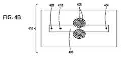
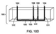
本開示は、独立型エレクトロポレーション装置としての使用および自動化されたマルチモジュール細胞処理環境での使用の両方のために構成されたエレクトロポレーション装置を提供する。この装置は、液体培地中の細胞に外因性物質を導入するためのフロースルーエレクトロポレーション(FTEP)装置を含み、装置は、FTEP装置に細胞および外因性物質を導入するための入口および入口チャネルと、FTEP装置から形質転換された細胞を取り出すための出口チャネルおよび出口と、入口チャネルと出口チャネルの間に配置され、入口チャネルがフローチャネルに入る場所と出口チャネルがフローチャネルを出るポイントの間でフローチャネルの幅が任意に減少するフローチャネルと、2つの電極とを含む。いくつかの実施形態では、2つの電極は、フローチャネルの幅が減少する場所においてフローチャネルの壁の一部を形成する。他の実施形態において、電極は、第1の電極チャネルが、第1の電極を入口チャネルとフローチャネルの狭窄部との間のフローチャネルに流体連通し、第2の電極チャネルが、第2の電極を出口チャネルとフローチャネルの狭窄部との間のフローチャネルに流体連通するように配置されてもよい。 The present disclosure provides an electroporation apparatus configured for both use as a stand-alone electroporation apparatus and for use in an automated multi-module cell processing environment. This device includes a flow-through electroporation (FTEP) device for introducing exogenous substances into cells in a liquid medium, and the device is an inlet and inlet channel for introducing cells and exogenous substances into the FTEP device. And between the exit and exit channels for removing transformed cells from the FTEP device and between the inlet and outlet channels, where the inlet channel enters the flow channel and where the exit channel exits the flow channel. Includes a flow channel in which the width of the flow channel is arbitrarily reduced and two electrodes. In some embodiments, the two electrodes form part of the wall of the flow channel where the width of the flow channel is reduced. In another embodiment, the electrode is such that the first electrode channel fluidly communicates the first electrode to the flow channel between the inlet channel and the constriction of the flow channel, and the second electrode channel is the second. Electrodes may be arranged to communicate fluid with the flow channel between the outlet channel and the constriction of the flow channel.
したがって、特定の実施形態では、流体中の細胞に外因性物質を導入するためのフロースルーエレクトロポレーション(FTEP)装置が提供され、FTEP装置は、細胞および外因性物質を含む流体をFTEP装置に入れるための少なくとも第1の入口および少なくとも第1の入口チャネルと、FTEP装置から形質転換された細胞および外因性物質を含む流体を取り出すための出口および出口チャネルと、第1の入口チャネルおよび出口チャネルと交差し第1の入口チャネルと出口チャネルとの間に配置され、第1の入口チャネルとフローチャネルの中心と、出口チャネルとフローチャネルの中心との間で幅が減少するフローチャネルと、フローチャネルと第1の入口チャネルとの交差点と、フローチャネルと出口チャネルとの交差点との間でかつ、フローチャネルの幅が減少する場所の両端にある電極チャネルに配置された2つの電極であって、電極は、フローチャネル内の流体と流体連通している。そして、電極は、細胞を含む流体がフローチャネルを通過する際に、細胞に1つ以上の電気パルスを印加し、それにより、流体中の細胞に外因性物質を導入する。 Therefore, in certain embodiments, a flow-through electroporation (FTEP) device for introducing an exogenous substance into a cell in a fluid is provided, the FTEP device making the fluid containing the cell and the exogenous substance into the FTEP device. At least a first inlet and at least a first inlet channel for entry, an outlet and exit channels for extracting fluid containing transformed cells and exogenous substances from the FTEP apparatus, and a first inlet and outlet channel. A flow channel that intersects with and is located between the first inlet and exit channels and has a reduced width between the center of the first inlet and flow channels and the center of the exit and flow channels, and the flow. Two electrodes located at the intersection of the channel with the first inlet channel and between the intersection of the flow channel and the exit channel and at both ends of the location where the width of the flow channel decreases. , The electrodes are in fluid communication with the fluid in the flow channel. The electrodes then apply one or more electrical pulses to the cells as the fluid containing the cells pass through the flow channel, thereby introducing exogenous material into the cells in the fluid.
この実施形態のいくつかの態様では、FTEP装置は、流体中の細胞をFTEP装置に導入するための少なくとも第1の入口に接続されたリザーバ(reservoir)と、FTEP装置から形質転換された細胞を取り出すための出口に接続されたリザーバとをさらに備える。この実施形態のいくつかの態様において、入口および出口に連結されたリザーバは、体積が100μLから10ml、または0.5mlから7ml、または1mlから5mlの範囲である。 In some embodiments of this embodiment, the FTEP device comprises a reservoir connected to at least a first inlet for introducing cells in fluid into the FTEP device and cells transformed from the FTEP device. Further provided with a reservoir connected to an outlet for removal. In some embodiments of this embodiment, the reservoirs connected to the inlet and outlet range in volume from 100 μL to 10 ml, or 0.5 ml to 7 ml, or 1 ml to 5 ml.
この実施形態のいくつかの態様では、FTEP装置は、2つの入口および2つの入口チャネルを備え、外因性物質をFTEP装置に導入するための第2の入口に接続されたリザーバをさらに備える。この態様のいくつかの構成において、第2の入口および第2の入口チャネルは、第1の入口および第1の入口チャネルと電極との間に位置する。また、いくつかの構成では、第2の入口および第2の入口チャネルは、電極と出口チャネルおよび出口との間に位置する。 In some embodiments of this embodiment, the FTEP device comprises two inlets and two inlet channels, further comprising a reservoir connected to a second inlet for introducing exogenous material into the FTEP device. In some configurations of this embodiment, the second inlet and the second inlet channel are located between the first inlet and the first inlet channel and the electrode. Also, in some configurations, the second inlet and second inlet channels are located between the electrodes and the outlet channels and outlets.
この実施形態のいくつかの態様では、FTEP装置の2つの電極は、0.5mmから10mm離れて、または1mmから8mm離れて、または3mmから7mm離れて、または4mmから6離れて位置する。この実施形態のいくつかの態様では、FTEP装置は、長さが3cmから15cm、または長さが4cmから12cm、または長さが4.5cmから10cm、または長さが5cmから8cmである。この実施形態のいくつかの態様において、FTEP装置のこの実施形態は、0.5cmから5cmの幅、または0.75cmから3cmの幅、または1cmから2.5cmの幅、または1cmから1.5cmの幅である。この実施形態のいくつかの態様では、FTEP装置のチャネル幅の最狭窄部分は10μmから5mmである。In some embodiments of this embodiment, the two electrodes of the FTEP device are located 0.5 mm to 10 mm apart, or 1 mm to 8 mm apart, or 3 mm to 7 mm apart, or 4 mm to 6 apart. In some embodiments of this embodiment, the FTEP device is 3 cm to 15 cm in length, or 4 cm to 12 cm in length, or 4.5 cm to 10 cm in length, or 5 cm to 8 cm in length. In some embodiments of this embodiment, this embodiment of the FTEP device is 0.5 cm to 5 cm wide, or 0.75 cm to 3 cm wide, or 1 cm to 2.5 cm wide, or 1 cm to 1.5 cm wide. The width of. In some embodiments of this embodiment, the narrowest portion of the channel width of the FTEP device is 10μm to 5 mm.
この実施形態のいくつかの態様では、FTEPの流量は、毎分0.1mlから5ml、または毎分0.5mlから3ml、または毎分1mlから2.5mlの範囲である。
この実施形態のいくつかの態様では、電極は、1〜25Kv/cm、または10〜20Kv/cmを送達するように構成される。In some embodiments of this embodiment, the flow rate of FTEP ranges from 0.1 ml to 5 ml per minute, or 0.5 ml to 3 ml per minute, or 1 ml to 2.5 ml per minute.
In some embodiments of this embodiment, the electrodes are configured to deliver 1-25 Kv / cm, or 10-20 Kv / cm.
この実施形態のいくつかの態様では、FTEP装置は、1つまたは複数の入口チャネルと出口チャネルとの間に、1つまたは複数のフィルタをさらに備える。いくつかの態様では、2つのフィルタがあり、1つは入口チャネルとフローチャネルの狭窄部との間にあり、もう1つはフローチャネルの狭窄部と出口チャネルの間にある。この実施形態のいくつかの態様では、フィルタは、入口チャンバまたは出口チャンバに近位の大孔を有し、およびフローチャネルの狭窄部に近位の細孔を有するような孔サイズで目盛りが付けられている。いくつかの態様では、細孔は、フローチャネルの狭窄部のサイズと同じサイズまたはそれより大きい。この実施形態のいくつかの態様では、フィルタは、FTEP装置の本体とは別個に形成され、アセンブリされているときにFTEP装置に配置される。あるいは、この実施形態のいくつかの態様では、フィルタは、FTEP装置の本体の一部として形成されてもよく、本体と一体であってもよい。 In some embodiments of this embodiment, the FTEP device further comprises one or more filters between the one or more inlet and outlet channels. In some embodiments, there are two filters, one between the inlet channel and the flow channel stenosis and the other between the flow channel stenosis and the exit channel. In some embodiments of this embodiment, the filter is calibrated with a hole size such that it has a foramen magnum proximal to the inlet or outlet chamber and pores proximal to the constriction of the flow channel. Has been done. In some embodiments, the pores are the same size or larger than the size of the narrowed portion of the flow channel. In some embodiments of this embodiment, the filter is formed separately from the body of the FTEP device and placed in the FTEP device when assembled. Alternatively, in some embodiments of this embodiment, the filter may be formed as part of the body of the FTEP device or may be integral with the body.
この実施形態のいくつかの態様では、FTEP装置は、毎分103〜1012細胞、または毎分104〜1010、毎分105〜109、または毎分106〜108の細胞形質転換率を提供することができる。通常、1分あたり108個の酵母細胞が形質転換され、1分あたり1010〜1011個の細菌細胞が形質転換される。In some embodiments of this embodiment, the FTEP device is 103 to 1012 cells per minute, or 104 to 1010 per minute, 105 to 109 per minute, or 106 to 108 cells per minute. Transformation rates can be provided. Usually, 108 yeast cells per minute is transformed,10 1010 11 pieces of bacterial cells per 1 minute is transformed.
この実施形態のいくつかの態様では、細胞の形質転換は、少なくとも90%の生存細胞、または95%の生存細胞、および最大99%の生存細胞をもたらす。
この実施形態のいくつかの態様では、FTEP装置は、結晶スチレン、シクロオレフィンポリマー、またはシクロオレフィンコポリマーから射出成形によって製造され、この実施形態のいくつかの態様では、電極はステンレス鋼から製造される。In some embodiments of this embodiment, cell transformation results in at least 90% viable cells, or 95% viable cells, and up to 99% viable cells.
In some embodiments of this embodiment, the FTEP apparatus is manufactured by injection molding from crystalline styrene, cycloolefin polymer, or cycloolefin copolymer, and in some embodiments of this embodiment, the electrodes are manufactured from stainless steel. ..
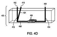
さらに別の実施形態では、外因性物質を流体中の細胞に導入するためのフロースルーエレクトロポレーション(FTEP)装置を提供する。FTEP装置は、細胞および外因性物質を含む流体を導入するための少なくとも1つの入口および少なくとも1つの入口チャネルと、FTEP装置から形質転換された細胞および外因性物質を取り出すための出口および出口チャネルと、第1の入口チャネルと出口チャネルの間に位置し、フローチャネルが第1の入口チャネルと出口チャネルと交差し、フローチャネルの一部が、フローチャネルと入口チャネルの交差点とフローチャネルと出口チャネルの交差点との間で狭くなるフローチャネルと、フローチャネルの両側に配置され、フローチャネル内の流体と直接接触し、フローチャネルの狭窄部を画定する電極とを含む。そして、電極は、流体中の細胞がフローチャネルを通過するときに、流体中の細胞に1つまたは複数に電気パルスを印加し、それにより、流体中の細胞に外因性物質を導入する。 Yet another embodiment provides a flow-through electroporation (FTEP) apparatus for introducing an exogenous substance into cells in a fluid. The FTEP device has at least one inlet and at least one inlet channel for introducing a fluid containing cells and exogenous substances, and an exit and exit channel for extracting transformed cells and exogenous substances from the FTEP device. , Located between the first inlet and exit channels, the flow channel intersects the first inlet and exit channels, and some of the flow channels are at the intersection of the flow channel and the inlet channel and the flow channel and the exit channel. Includes a flow channel that narrows to and from the intersection of the flow channel and electrodes that are located on either side of the flow channel and that are in direct contact with the fluid in the flow channel and define the constriction of the flow channel. The electrode then applies an electrical pulse to the cells in the fluid, one or more, as the cells in the fluid pass through the flow channel, thereby introducing the exogenous substance into the cells in the fluid.
いくつかの態様では、FTEP装置は、流体中の細胞をFTEP装置に導入するための入口に接続されたリザーバと、FTEP装置から形質転換された細胞を取り出すための出口に接続されたリザーバとをさらに備える。いくつかの態様では、FTEP装置は2つの入口と2つの入口チャネルを備え、外因性物質をFTEP装置に導入するための第2の入口に接続されたリザーバをさらに備える。この実施形態のいくつかの態様において、入口および出口に連結されたリザーバは、体積が100μLから10ml、または0.5mlから7ml、または1mlから5mlの範囲である。 In some embodiments, the FTEP device comprises a reservoir connected to an inlet for introducing cells in fluid into the FTEP device and a reservoir connected to an outlet for removing transformed cells from the FTEP device. Further prepare. In some embodiments, the FTEP device comprises two inlets and two inlet channels, further comprising a reservoir connected to a second inlet for introducing exogenous material into the FTEP device. In some embodiments of this embodiment, the reservoirs connected to the inlet and outlet range in volume from 100 μL to 10 ml, or 0.5 ml to 7 ml, or 1 ml to 5 ml.
この実施形態のいくつかの態様では、第2の入口および第2の入口チャネルは、第1の入口および第1の入口チャネルと電極との間に位置する。また、いくつかの構成では、第2の入口および第2の入口チャネルは、電極と出口チャネルおよび出口との間に位置する。 In some embodiments of this embodiment, the second inlet and the second inlet channel are located between the first inlet and the first inlet channel and the electrode. Also, in some configurations, the second inlet and second inlet channels are located between the electrodes and the outlet channels and outlets.
この実施形態のいくつかの態様では、FTEP装置の2つの電極は、10μmから1mm離れて、または25μmから3mm離れて、または50μmから2mm離れて、または75μmから1mm離れて位置する。この実施形態のいくつかの態様では、FTEP装置は、長さが3cmから15cm、または長さが4cmから12cm、または長さが4.5cmから10cm、または長さが0.5cmから8cmである。この実施形態のいくつかの態様では、FTEP装置は、幅が0.5cmから5cm、または幅が0.75cmから3cm、または幅が1cmから2.5cm、または幅が1cmから1.5cmである。この実施形態のいくつかの態様では、FTEP装置のチャネル幅の最狭窄部分は10μmから5mmであり、いくつかの態様では、チャネル幅の最狭窄部分は10μmから1mmである。
In some embodiments of this embodiment, the two electrodes of the FTEP device are located 1 mm from 10 μm, or 3 mm from 25 μm, or 2 mm from 50 μm, or 1 mm from 75 μm. In some embodiments of this embodiment, the FTEP device is 3 cm to 15 cm in length, or 4 cm to 12 cm in length, or 4.5 cm to 10 cm in length, or 0.5 cm to 8 cm in length. .. In some embodiments of this embodiment, the FTEP device is 0.5 cm to 5 cm wide, or 0.75 cm to 3 cm wide, or 1 cm to 2.5 cm wide, or 1 cm to 1.5 cm wide. .. In some embodiments of this embodiment, the narrowest portion of the channel width of the FTEP device is 10μm to 5 mm, and in someembodiments, the narrowest portion of the channel width is 10 μm to 1 mm.
この実施形態のいくつかの態様では、FTEPの流量は、毎分0.1mlから5ml、または毎分0.5mlから3ml、または毎分1mlから2.5mlの範囲である。
この実施形態のいくつかの態様では、電極は、1〜25Kv/cm、または10〜20Kv/cmを送達するように構成される。In some embodiments of this embodiment, the flow rate of FTEP ranges from 0.1 ml to 5 ml per minute, or 0.5 ml to 3 ml per minute, or 1 ml to 2.5 ml per minute.
In some embodiments of this embodiment, the electrodes are configured to deliver 1-25 Kv / cm, or 10-20 Kv / cm.
この実施形態のいくつかの態様では、FTEP装置は、1つまたは複数の入口チャネルと出口チャネルとの間に、1つまたは複数のフィルタをさらに備える。いくつかの態様では、2つのフィルタがあり、1つのフィルタは入口チャネルとフローチャネルの狭窄部との間にあり、もう1つのフィルタはフローチャネルの狭窄部と出口チャネルの間にある。この実施形態のいくつかの態様では、フィルタは、入口チャンバまたは出口チャンバに近位の大孔を有し、およびフローチャネルの狭窄部に近位の細孔を有するような孔サイズで目盛りが付けられている。いくつかの態様では、細孔は、フローチャネルの狭窄部のサイズと同じサイズまたはそれより大きい。この実施形態のいくつかの態様では、フィルタは、FTEP装置の本体とは別個に形成され、アセンブリされているときにFTEP装置に配置される。あるいは、この実施形態のいくつかの態様では、フィルタは、FTEP装置の本体の一部として形成されてもよく、本体と一体であってもよい。 In some embodiments of this embodiment, the FTEP device further comprises one or more filters between the one or more inlet and outlet channels. In some embodiments, there are two filters, one between the inlet channel and the flow channel stenosis and the other between the flow channel stenosis and the exit channel. In some embodiments of this embodiment, the filter is calibrated with a hole size such that it has a foramen magnum proximal to the inlet or outlet chamber and pores proximal to the constriction of the flow channel. Has been done. In some embodiments, the pores are the same size or larger than the size of the narrowed portion of the flow channel. In some embodiments of this embodiment, the filter is formed separately from the body of the FTEP device and placed in the FTEP device when assembled. Alternatively, in some embodiments of this embodiment, the filter may be formed as part of the body of the FTEP device or may be integral with the body.
この実施形態のいくつかの態様では、FTEP装置は、毎分103〜1012細胞、または毎分104〜1010、毎分105〜109、または毎分106〜108の細胞形質転換率を提供することができる。通常、108個の酵母細胞が1分あたりに形質転換され、1010〜1011個の細菌細胞が1分あたりに形質転換される。In some embodiments of this embodiment, the FTEP device is 103 to 1012 cells per minute, or 104 to 1010 per minute, 105 to 109 per minute, or 106 to 108 cells per minute. Transformation rates can be provided. Usually, 108 yeast cells transformed perminute, 10 1010 11 pieces of bacterial cell is transformed per minute.
この実施形態のいくつかの態様において、細胞の形質転換は、少なくとも90%の生存細胞、または95%の生存細胞、および最大99%の生存細胞をもたらす。
この実施形態のいくつかの態様では、FTEP装置は、結晶スチレン、シクロオレフィンポリマー、またはシクロオレフィンコポリマーから射出成形によって製造され、いくつかの態様では、電極はステンレス鋼から製造される。In some embodiments of this embodiment, cell transformation results in at least 90% viable cells, or 95% viable cells, and up to 99% viable cells.
In some embodiments of this embodiment, the FTEP apparatus is manufactured by injection molding from crystalline styrene, cycloolefin polymer, or cycloolefin copolymer, and in some embodiments, the electrodes are manufactured from stainless steel.
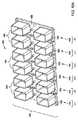
いずれかの実施形態のいくつかの態様では、FTEP装置は、単一基板上に複数のFTEP装置として並行して製造され、FTEP装置は使用目的で分離される。
いずれかの実施形態のいくつかの態様では、FTEP装置は試薬カートリッジの一部であり、いくつかの態様では、試薬カートリッジはFTEP装置の操作指示を提供するスクリプトを含む。In some embodiments of any of the embodiments, the FTEP device is manufactured in parallel as multiple FTEP devices on a single substrate, and the FTEP device is separated for use.
In some embodiments of any embodiment, the FTEP device is part of a reagent cartridge, and in some embodiments, the reagent cartridge comprises a script that provides operational instructions for the FTEP device.
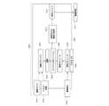
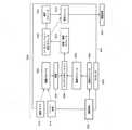
いずれかの実施形態のいくつかの態様において、FTEP装置は、自動化されたマルチモジュール細胞処理システムの一部であるモジュールに含まれ、自動化されたマルチモジュール細胞処理システムは、1つ以上の細胞用のレセプタクル、細胞にエレクトロポレーションされる核酸または他の材料用の1つ以上の容器、成長モジュール、濾過モジュール、回復モジュール、核酸アセンブリモジュール、精製モジュール、編集モジュール、シンギュレーションおよび成長モジュール、選択モジュール、保存モジュール、およびプロセッサを含む。 In some embodiments of any of the embodiments, the FTEP apparatus is included in a module that is part of an automated multi-module cell processing system, the automated multi-module cell processing system for one or more cells. Receptacles, one or more containers for nucleic acids or other materials electroporated into cells, growth modules, filtration modules, recovery modules, nucleic acid assembly modules, purification modules, editing modules, singulation and growth modules, selection Includes modules, storage modules, and processors.
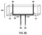
さらに、流体中の細胞に外因性物質を導入するためのフロースルーエレクトロポレーション(FTEP)装置の別の実施形態が提示される。FTEP装置は、細胞または外因性物質を含む流体を受け入れるための少なくとも第1の入口と、流体を受け取るために第1の入口に流体的に結合された狭窄領域を有し、狭窄領域は流体の流れを閉じ込めるフローチャネルと、フローチャネルの狭窄領域内の流体と電気的に連通して配置された少なくとも2つの電極であって、電極がフローチャネルまたはフローチャネルの狭窄領域を通過する際に細胞または外因性物質に電界を印加し、それにより形質転換された細胞を形成するように構成された電極と、フローチャネルの狭窄領域に連結され、形質転換された細胞を受け入れるように構成された少なくとも1つの出口とを備える。いくつかの態様では、少なくとも2つの電極は、流体と直接接触するように構成される。この実施形態のいくつかの態様において、フローチャネルは、細胞に運動量を与える非線形経路をたどり、細胞の少なくとも一部がチャネル内に配置された物体の周りを流れるようにする。いくつかの態様では、FTEP装置は、第1の電極の近位端を受け入れるためのフローチャネルの狭窄領域の近位にある少なくとも1つの開口をさらに備え、それにより第1の電極は流体と直接接触する。さらに、いくつかの態様では、開口部は丸い縁を含む。この実施形態のいくつかの態様では、フローチャネルの狭窄領域は第1の断面寸法を有し、少なくとも2つの電極は、その寸法に沿ってフローチャネルの狭窄領域を部分的に横切って延びる。 In addition, another embodiment of a flow-through electroporation (FTEP) device for introducing exogenous material into cells in a fluid is presented. The FTEP device has at least a first inlet for receiving fluid containing cells or exogenous substances and a constriction region fluidly coupled to the first inlet to receive the fluid, the constriction region being of fluid. A flow channel that traps the flow and at least two electrodes that are placed in electrical communication with the fluid within the constricted area of the flow channel, such as cells or cells as the electrodes pass through the constricted area of the flow channel or flow channel. An electrode configured to apply an electric field to an exogenous substance to form transformed cells and at least one linked to a constricted region of a flow channel and configured to receive transformed cells. Equipped with two exits. In some embodiments, the at least two electrodes are configured to be in direct contact with the fluid. In some embodiments of this embodiment, the flow channel follows a non-linear pathway that imparts momentum to the cell, allowing at least a portion of the cell to flow around an object placed within the channel. In some embodiments, the FTEP device further comprises at least one opening proximal to the constricted region of the flow channel for receiving the proximal end of the first electrode, whereby the first electrode is directly with the fluid. Contact. In addition, in some embodiments, the opening comprises a rounded edge. In some embodiments of this embodiment, the constricted region of the flow channel has a first cross-sectional dimension, and at least two electrodes extend along the dimension partially across the constricted region of the flow channel.
他の実施形態と同様に、FTEP装置は、流体中の細胞をFTEP装置に導入するための入口に接続されたリザーバと、FTEP装置から形質転換された細胞を取り出すための出口に接続されたリザーバをさらに含む。 Similar to other embodiments, the FTEP device has a reservoir connected to an inlet for introducing cells in fluid into the FTEP device and a reservoir connected to an outlet for removing transformed cells from the FTEP device. Including further.
すべての実施形態のいくつかの態様において、FTEP装置は、FTEP装置の加圧および圧力駆動流の提供を可能にするシールをさらに備える。いくつかの態様では、FTEP装置は、少なくとも複数の細胞がフローチャネルの狭窄領域を複数回横断するように、フローチャネルを通して流体を駆動するポンプをさらに含む。 In some embodiments of all embodiments, the FTEP device further comprises a seal that allows the pressurization and pressure drive flow of the FTEP device to be provided. In some embodiments, the FTEP device further comprises a pump that drives the fluid through the flow channel such that at least multiple cells traverse the narrowed region of the flow channel multiple times.
すべての実施形態のいくつかの態様では、FTEP装置は、少なくとも2つの電極に時変電圧を印加するための電圧源をさらに備える。
前述の実施形態と同様に、FTEPのこの実施形態の一態様は、流体を受け入れて保持するために第1の入口に接続された第1のリザーバと、形質転換された細胞を受け入れるために出口に接続された第2のリザーバとをさらに含む。いくつかの態様では、FTEP装置は、FTEP装置内の細胞に導入される外因性物質を受け入れるための第2の入口をさらに備え、前記入口は、フローチャネルの狭窄領域と流体連通する。また、いくつかの態様では、FTEP装置は、細胞よりも実質的に大きい物体のフローチャネルの狭窄領域への透過を防ぐように構成されたフィルタ要素をさらに備え、この実施形態のいくつかの態様では、フィルタ要素は、フローチャネルの狭窄領域を形成する構造、およびいくつかの態様では、フィルタ要素は、フローチャネルの狭窄領域の近位にある位置に向かうに連れ次第に小さな開口を有する。In some embodiments of all embodiments, the FTEP device further comprises a voltage source for applying a time-varying voltage to at least two electrodes.
Similar to the previous embodiment, one aspect of this embodiment of the FTEP is a first reservoir connected to a first inlet to receive and hold the fluid and an exit to receive the transformed cells. Further includes a second reservoir connected to. In some embodiments, the FTEP device further comprises a second inlet for receiving an exogenous substance introduced into the cells within the FTEP device, which is in fluid communication with the constricted region of the flow channel. Also, in some embodiments, the FTEP device further comprises a filter element configured to prevent permeation of the flow channel of an object substantially larger than the cell into the constricted region, in some embodiments of this embodiment. In, the filter element has a structure that forms a constricted region of the flow channel, and in some embodiments, the filter element has a progressively smaller opening towards a position proximal to the constricted region of the flow channel.
他の実施形態では、外因性物質を流体中の細胞に導入するためのフロースルーエレクトロポレーション(FTEP)装置が提供され、装置は、細胞および外因性物質を含む流体を導入するための少なくとも1つの入口および少なくとも1つの入口チャネルと、FTEP装置から形質転換された細胞および外因性物質を取り出すための出口および出口チャネルと、第1の入口チャネルと出口チャネルとの間に配置されたフローチャネルであって、第1の入口チャネルおよび出口チャネルと交差し、入口チャネル交差点と出口チャネル交差点との間でフローチャネルの一部が狭まるフローチャネルと、フローチャネルの狭窄部の両側に配置され、フローチャネル内の流体と直接接触し、フローチャネルの狭窄部を画定する電極とを備える。そして、電極は、細胞を含む流体がフローチャネルを通過するときに、流体中の1つまたは複数の細胞に電気パルスを印加し、それにより、流体中の細胞に外因性物質を導入する。 In another embodiment, a flow-through electroporation (FTEP) device for introducing an exogenous substance into a cell in a fluid is provided, the device being at least one for introducing the cell and the fluid containing the exogenous substance. At one inlet and at least one inlet channel, an exit and exit channel for extracting transformed cells and exogenous substances from the FTEP apparatus, and a flow channel located between the first inlet and exit channels. There is a flow channel that intersects the first inlet and exit channels and narrows part of the flow channel between the inlet and exit channel intersections, and is located on either side of the narrowed portion of the flow channel and is a flow channel. It is provided with an electrode that comes into direct contact with the fluid inside and defines a constriction in the flow channel. The electrode then applies an electrical pulse to one or more cells in the fluid as the fluid containing the cells passes through the flow channel, thereby introducing exogenous material into the cells in the fluid.
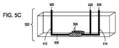
さらに他の実施形態は、外因性物質を流体中の細胞に導入するためのフロースルーエレクトロポレーション(FTEP)装置を提供する。FTEP装置は、FTEP装置へ細胞/外因性物質を含む流体を受け入れるための少なくとも第1の入口および少なくとも第1の入口チャネルと、FTEP装置から形質転換された細胞/外因性物質を含む流体を取り出すための出口および出口チャネルと、少なくとも第1の入口チャネルおよび出口チャネルと交差し少なくとも第1の入口チャネルと出口チャネルとの間に配置されたフローチャネルと、フローチャネルと第1の入口チャネルとの交差点と、フローチャネルと出口チャネルとの交差点との間の電極チャネルに配置された2つの電極であって、フローチャネル内の流体と電気的に連通し、フローチャネル内を通過する際に流体中の1つまたは複数の細胞に電気パルスを印加し、それにより、流体中の細胞に外因性物質を導入する電極と、少なくとも第1の入口チャネルと電極チャネルとの間に配置されたフィルタとを含む。 Yet another embodiment provides a flow-through electroporation (FTEP) apparatus for introducing an exogenous substance into cells in a fluid. The FTEP apparatus extracts at least a first inlet and at least a first inlet channel for receiving a fluid containing cells / exogenous substances into the FTEP apparatus and a fluid containing transformed cells / exogenous substances from the FTEP apparatus. An exit and exit channel for, a flow channel intersecting at least the first inlet and exit channels and located between at least the first inlet and exit channels, and a flow channel and a first inlet channel. Two electrodes located in the electrode channel between the intersection and the intersection of the flow channel and the exit channel, electrically communicating with the fluid in the flow channel and in the fluid as it passes through the flow channel. An electrical pulse is applied to one or more cells in a fluid to introduce an exogenous substance into the cells in a fluid, and a filter placed between at least the first inlet channel and the electrode channel. include.
一つの態様では、フィルタはFTEP装置の一部として一体的に形成され、一つの態様では、フィルタおよびFTEP装置は射出成形により形成される。いくつかの態様では、フィルタは勾配フィルタであり、いくつかの態様では、勾配は少なくとも第1の入口チャネルの近位にある大孔と、電極チャネルの近位にある細孔とを含む。フィルタ付きのFTEP装置のいくつかの態様では、電極と出口チャネルの間に配置された第2のフィルタがあり、いくつかの態様では、両方のフィルタがFTEP装置の一部として一体的に形成される。この実施形態のいくつかの態様では、両方のフィルタは勾配フィルタであり、いくつかの態様では、1つの勾配フィルタは少なくとも第1の入口チャネルの近位にある大孔と電極チャネルの近位にある細孔とを含み、他の勾配フィルタは出口チャネルの近位にある大孔を含み、電極チャネルの近位にある細孔を含む。 In one embodiment, the filter is integrally formed as part of the FTEP device, and in one embodiment, the filter and FTEP device are formed by injection molding. In some embodiments, the filter is a gradient filter, and in some embodiments, the gradient comprises foramen magnums at least proximal to the first inlet channel and pores proximal to the electrode channel. In some embodiments of the FTEP device with a filter, there is a second filter located between the electrode and the outlet channel, and in some embodiments both filters are integrally formed as part of the FTEP device. To. In some embodiments of this embodiment, both filters are gradient filters, and in some embodiments, one gradient filter is at least proximal to the large hole and electrode channel proximal to the first inlet channel. Some pores and other gradient filters include large pores proximal to the exit channel and pores proximal to the electrode channel.
この実施形態のいくつかの態様では、フローチャネルの幅は、第1の入口チャネルとフローチャネルの中心と出口チャネルとフローチャネルの中心との間で減少し、この実施形態のいくつかの態様では、2つ電極は、フローチャネルと第1の入口チャネルとの交差点と、フローチャネルと出口チャネルとの交差点との間でかつ、フローチャネルの幅が減少する場所の両端の電極チャネルに配置される。 In some embodiments of this embodiment, the width of the flow channel is reduced between the center of the first inlet and flow channels and the center of the exit and flow channels, and in some embodiments of this embodiment. Two electrodes are arranged in the electrode channels between the intersection of the flow channel and the first inlet channel, the intersection of the flow channel and the exit channel, and at both ends where the width of the flow channel is reduced. ..
フィルタを含むFTEP装置の実施形態の態様では、フィルタ要素は「ペグ」または「突起」を含み、「ペグ」または「突起」は形状が円形、長円形、楕円形、または多角形であってもよい。 In an embodiment of an FTEP device comprising a filter, the filter element comprises a "peg" or "protrusion", even if the "peg" or "protrusion" is circular, oval, oval, or polygonal in shape. good.
さらに別の実施形態は、細胞をエレクトロポレーションする方法を提供する。その方法は、エレクトロコンピテント細胞および外因性物質を含む流体を受け入れるための入口および少なくとも1つの入口チャネルと、FTEP装置から形質転換された細胞および外因性物質を含む流体を取り出すための出口および出口チャネルと、入口チャネルおよび出口チャネルと交差し入口チャネルと出口チャネルの間に配置されたフローチャネルと、フローチャネルと入口チャネルとの交差点と、フローチャネルと出口チャネルとの交差点との間に配置され、フローチャネル内の流体と電気的に連通する2つの電極と、を含むフロースルーエレクトロポレーション(FTEP)装置を用意することと、エレクトロコンピテントセルと外因性物質を含む細胞を入口と入口チャネルに流し、細胞をフローチャネルに流し、2つの電極を通過させることと、細胞が電極を通過してフローチャネルを通って流れるとき、流体中の細胞に電気パルスを提供してエレクトロポレーションされた細胞を生成することと、エレクトロポレーションされた細胞を出口チャネルおよび出口から取り出すことと、を含む。 Yet another embodiment provides a method of electroporating cells. The method consists of an inlet and at least one inlet channel for receiving electrocompetent cells and fluid containing exogenous substances, and an outlet and outlet for extracting fluid containing transformed cells and exogenous substances from the FTEP apparatus. It is located between the channel, the flow channel that intersects the inlet and exit channels and is located between the inlet and exit channels, the intersection of the flow channel and the inlet channel, and the intersection of the flow channel and the exit channel. To provide a flow-through electroporation (FTEP) device, including two electrodes that electrically communicate with the fluid in the flow channel, and an inlet and inlet channel for cells containing electrocompetent cells and exogenous substances. The cells were electroporated by providing electrical pulses to the cells in the fluid as they flowed through the flow channels and through the two electrodes and through the flow channels. Includes cell generation and removal of electroporated cells from exit channels and outlets.
いくつかの態様では、FTEP装置のフローチャネルは、入口チャネルとフローチャネルの中間領域と出口チャネルとフローチャネルの中間領域との間の幅が減少し、この実施形態のいくつかの態様では、フローチャネルの幅は、10μm〜5mm、または50μm〜2mm、またはエレクトロポレーションされる細胞の直径の少なくとも2倍より小さくならない寸法まで減少する。 In some embodiments, the flow channel of the FTEP device has a reduced width between the intermediate region of the inlet and flow channels and the intermediate region of the exit and flow channels, and in some embodiments of this embodiment the flow. The width of the channel is reduced to a size not less than 10 μm to 5 mm, or 50 μm to 2 mm, or at least twice the diameter of the electroporated cell.
いくつかの態様では、電極は、1〜25Kv/cmの電圧、または5〜20Kv/cmの電圧、または10〜20Kv/cmの電圧を送達するように構成される。いくつかの態様において、FTEP装置の流量は、毎分0.1mlから5mlの間、または毎分0.5mlから3mlの間である。 In some embodiments, the electrodes are configured to deliver a voltage of 1 to 25 Kv / cm, or a voltage of 5 to 20 Kv / cm, or a voltage of 10 to 20 Kv / cm. In some embodiments, the flow rate of the FTEP device is between 0.1 ml and 5 ml per minute, or between 0.5 ml and 3 ml per minute.
この実施形態のいくつかの態様では、2つの電極はそれぞれ電極チャネル内に配置され、1つの電極は入口チャネルとフローチャネルの中間領域との間に配置され、1つの電極は出口チャネルとフローチャネルの中央領域との間に配置される。この態様のいくつかの構成では、電極は0.5mmから10mm離れているか、3mmから7mm離れている。 In some embodiments of this embodiment, two electrodes are respectively located within the electrode channel, one electrode is located between the intermediate region of the inlet channel and the flow channel, and one electrode is the exit channel and the flow channel. It is placed between the central area of the. In some configurations of this embodiment, the electrodes are separated by 0.5 mm to 10 mm or 3 mm to 7 mm.
この実施形態のいくつかの態様では、電極は、フローチャネルの両側に配置され、フローチャネル内の流体と直接接触し、フローチャネルの幅の減少を規定する。この態様のいくつかの構成では、電極は10μmから5mm離れているか、25μmから2mm離れている。 In some embodiments of this embodiment, the electrodes are located on either side of the flow channel and are in direct contact with the fluid within the flow channel, defining a reduction in the width of the flow channel. In some configurations of this embodiment, the electrodes are separated by 5 mm from 10 μm or 2 mm from 25 μm.
この実施形態のいくつかの態様では、FTEP装置は、フローチャネル内に配置された少なくとも1つのフィルタをさらに備え、この態様のいくつかの構成では、フィルタはFTEP装置の一部として一体形成される。いくつかの構成では、フィルタは勾配フィルタであり、いくつかの構成では、勾配は、入口チャネルの近位にある大きな細孔と、電極の近位にある小さな細孔とを含む。さらに、いくつかの構成では、FTEP装置は、電極と出口チャネルの間に配置された第2のフィルタをさらに備え、いくつかの構成では、両方のフィルタがFTEP装置の一部として一体に形成される。また、2つのフィルタがあるいくつかの構成では、1つの勾配フィルタは入口チャネルの近位にある大孔と電極の近位にある細孔を含み、もう1つの勾配フィルタは出口チャネルの近位にある大孔と電極の近位にある細孔を含む。 In some embodiments of this embodiment, the FTEP device further comprises at least one filter disposed within the flow channel, and in some configurations of this embodiment, the filters are integrally formed as part of the FTEP device. .. In some configurations, the filter is a gradient filter, and in some configurations, the gradient contains large pores proximal to the inlet channel and small pores proximal to the electrode. Further, in some configurations, the FTEP device further comprises a second filter located between the electrode and the outlet channel, and in some configurations both filters are integrally formed as part of the FTEP device. To. Also, in some configurations with two filters, one gradient filter contains foramen magnum proximal to the inlet channel and pores proximal to the electrode, and the other gradient filter is proximal to the exit channel. Includes foramen magnum and pores proximal to the electrode.
さらに、細胞をエレクトロポレーションする方法を提供する。その方法は、エレクトロコンピテント細胞および外因性物質を含む流体を受け入れるための入口および少なくとも1つの入口チャネルと、FTEP装置から形質転換された細胞および外因性物質を含む流体を取り出すための出口および出口チャネルと、入口チャネルおよび出口チャネルと交差し入口チャネルと出口チャネルの間に配置されたフローチャネルと、フローチャネルと入口チャネルとの交差点と、フローチャネルと出口チャネルとの交差点との間に配置され、フローチャネル内の流体と電気的に連通する2つの電極と、を含むフロースルーエレクトロポレーション(FTEP)装置を用意することと、エレクトロコンピテントセルと外因性物質を含む細胞を入口と入口チャネルに流し、細胞をフローチャネルに流し、2つの電極を通過させることと、細胞が電極を通過してフローチャネルを通って流れるとき、流体中の細胞に電気パルスを提供してエレクトロポレーションされた細胞を生成することと、エレクトロポレーションされた細胞を出口チャネルおよび出口から取り出すことと、細胞の流れを逆転させて、出口から細胞を流し、出口チャネル、フローチャネルおよび2つの電極を通過させ、細胞がフローチャネルを流れるときに、流体中の細胞に電気パルスを提供し、そして、エレクトロポレーションされた細胞を入口チャネルおよび入口に流すことと、を含む。 In addition, it provides a method of electroporating cells. The method consists of an inlet and at least one inlet channel for receiving electrocompetent cells and fluid containing exogenous substances, and an outlet and outlet for extracting fluid containing transformed cells and exogenous substances from the FTEP apparatus. A flow channel that intersects the inlet and exit channels and is located between the inlet and exit channels, an intersection of the flow channel and the inlet channel, and an intersection of the flow channel and the exit channel. To provide a flow-through electroporation (FTEP) device, including two electrodes that electrically communicate with the fluid in the flow channel, and to enter and enter the cell containing the electrocompetent cell and the exogenous substance. The cells were electroporated by providing electrical pulses to the cells in the fluid as they flowed through the flow channels and through the two electrodes and through the flow channels. Generating cells, removing electroporated cells from the exit channel and exit, reversing the flow of cells, draining cells from the exit, passing through the exit channel, flow channel and two electrodes, As the cell flows through the flow channel, it provides an electrical pulse to the cell in the fluid and involves flowing the electroporated cell into the inlet channel and the inlet.
この実施形態のいくつかの態様は、エレクトロポレーションされた細胞を入口に流入させた後、細胞の流れを再び反転させて、入口から、入口チャネル、フローチャネル、および2つの電極を通過して細胞を流すことと、細胞が2つの電極を通過してフローチャネルを流れるときに、流体中の細胞に電気パルスを提供することと、エレクトロポレーションされた細胞を出口チャネルおよび出口から取り出すこととを更に含む。 Some embodiments of this embodiment allow electroporated cells to flow into the entrance and then reverse the flow of the cells again, from the entrance through the entrance channel, the flow channel, and the two electrodes. Flowing cells, providing electrical pulses to cells in fluid as they flow through the two electrodes and through the flow channel, and removing electroporated cells from the exit and exit channels. Further includes.
この実施形態のいくつかの態様において、FTEP装置のフローチャネルは、入口チャネルとフローチャネルの中央領域との間の幅が減少し、出口チャネルとフローチャネルの中央領域との間で幅が減少する。1つの態様では、フローチャネルの幅は、エレクトロポレーションされる細胞の直径の少なくとも2倍より少なくない寸法まで減少する。 In some embodiments of this embodiment, the flow channel of the FTEP device is reduced in width between the inlet channel and the central region of the flow channel and between the exit channel and the central region of the flow channel. .. In one embodiment, the width of the flow channel is reduced to a dimension not less than at least twice the diameter of the electroporated cells.
本発明のこれらの態様および他の特徴および利点は、以下により詳細に説明される。
本発明の前述および他の特徴および利点は、添付の図面と併せて、例示的な実施形態の以下の詳細な説明からより完全に理解されるであろう。These aspects and other features and advantages of the invention are described in more detail below.
The aforementioned and other features and advantages of the present invention, together with the accompanying drawings, will be more fully understood from the following detailed description of exemplary embodiments.
図面は必ずしも縮尺通りではなく、また、同様の参照番号は同様の特徴を指すことを理解されたい。
一実施形態に関連して説明される機能のすべては、明示的に述べられる場合、または特徴または機能が追加の実施形態と互換性がない場合を除き、本明細書に記載の追加の実施形態に適用可能である。たとえば、特定の機能または機能が一実施形態に関連して明示的に説明されているが、代替実施形態に関連して明示的に言及されていない場合、機能が代替実施形態と互換性がない場合を除き、機能または代替機能に関連して展開、利用、または実装できることを理解されたい。
本明細書に記載の技術の実施は、特に明記しない限り、当該分野における従来技術としての、従来の技術および説明分子生物学(組換え技術を含む)、細胞生物学、生化学、および遺伝子工学技術を採用してもよい。そのような従来の技術および説明は、あらゆる目的のために参照によりその全体が本明細書に組み込まれる「Green and Sambrook, Molecular Cloning: A Laboratory Manual.第4版」、「Cold Spring Harbor Laboratory Press, Cold Spring Harbor, N.Y.(2014)」、「Current Protocols in Molecular Biology, Ausubel, et al. eds., (2017)」、「Neumann, et al., Electroporation and Electrofusion in Cell Biology, Plenum Press, New York, 1989」、「Chang, et al., Guide to Electroporation and Electrofusion, Academic Press, California (1992)」などの標準的な実験室マニュアルに記載されている。It should be understood that drawings are not necessarily to scale and similar reference numbers refer to similar features.
All of the functions described in connection with an embodiment are the additional embodiments described herein, unless expressly stated or the features or functions are incompatible with the additional embodiments. Applicable to. For example, a function is incompatible with an alternative embodiment if a particular function or function is explicitly described in relation to one embodiment but not explicitly mentioned in relation to an alternative embodiment. Understand that it can be deployed, utilized, or implemented in connection with a feature or alternative feature, except as the case.
Unless otherwise stated, the practices described herein are prior art and explanatory molecular biology (including recombinant techniques), cell biology, biochemistry, and genetic engineering as prior art in the art. Technology may be adopted. Such prior art and description are incorporated herein by reference in their entirety for all purposes, "Green and Sambrook, Molecular Cloning: A Laboratory Manual. 4th Edition", "Cold Spring Harbor Laboratory Press,". Cold Spring Harbor, NY (2014) ”,“ Current Protocols in Molecular Biology, Ausubel, et al. Eds., (2017) ”,“ Neumann, et al., Electroporation and Electrofusion in Cell Biology, Plenum Press, New York, It is described in standard laboratory manuals such as "1989", "Chang, et al., Guide to Electroporation and Electrofusion, Academic Press, California (1992)".
本明細書および添付の特許請求の範囲で使用されるように、単数形「a」、「an」、および「the」は、文脈がそうでないことを明確に指示しない限り、複数の指示対象を含むことに留意されたい。したがって、例えば、「オリゴ」への言及は、同じ機能を果たす1つまたは複数のオリゴを指し、「方法」には、同等のステップおよび当業者に既知の方法への言及などが含まれる。すなわち、特に明記しない限り、本明細書で使用する「a」、「an」、「the」という言葉は「1つ以上」の意味を持っている。さらに、本明細書で使用される「左」、「右」、「頂」、「底」、「前」、「後」、「横」、「高さ」、「長さ」、「幅」、「上方」、「下方」、「内部」、「外部」、「内側」、「外側」などの用語は単に参照点を説明するものであり、本開示の実施形態を必ずしも特定の向きまたは構成に限定するものではない。さらに、「第1」、「第2」、「第3」などの用語は、本明細書で開示されるいくつかの部分、構成要素、ステップ、操作、機能、および/または参照点の1つを単に特定し、同様に特定する本開示の実施形態を特定の構成または向きに必ずしも限定するものではない。 As used herein and in the appended claims, the singular forms "a", "an", and "the" referent to multiple referents unless the context explicitly indicates otherwise. Please note that it includes. Thus, for example, reference to "oligo" refers to one or more oligos performing the same function, and "method" includes equivalent steps and references to methods known to those of skill in the art. That is, unless otherwise stated, the terms "a," "an," and "the" as used herein have the meaning of "one or more." In addition, "left", "right", "top", "bottom", "front", "rear", "horizontal", "height", "length", "width" as used herein. , "Upper", "Down", "Inside", "Outside", "Inside", "Outside", etc., merely describe a reference point, and the embodiments of the present disclosure are not necessarily in a particular orientation or configuration. It is not limited to. Further, terms such as "first", "second", "third" are one of several parts, components, steps, operations, functions, and / or reference points disclosed herein. The embodiments of the present disclosure are not necessarily limited to a particular configuration or orientation.
さらに、用語「およそ」、「近位」、「マイナー」、および類似の用語は、一般に、20%、10%、または10%の範囲内で識別された値、特定の実施形態では好ましくは5%、およびその間の任意の値を含む範囲を指す。 In addition, the terms "approximately", "proximal", "minor", and similar terms are generally values identified within the range of 20%, 10%, or 10%, preferably 5 in certain embodiments. Refers to a range that includes% and any value in between.
特に定義されない限り、本明細書で使用されるすべての技術用語および科学用語は、本発明が属する技術分野の当業者によって一般に理解されるのと同じ意味を有する。本明細書で言及されるすべての刊行物は、現在記載される発明に関連して使用され得る装置、製剤、および方法論を説明および開示する目的を含む、あらゆる目的で参照により組み込まれる。 Unless otherwise defined, all technical and scientific terms used herein have the same meaning as commonly understood by one of ordinary skill in the art to which the invention belongs. All publications referred to herein are incorporated by reference for any purpose, including for purposes of explaining and disclosing the devices, formulations, and methodologies that may be used in connection with the inventions currently described.
値の範囲が提供される場合、その範囲の上限と下限の間の各介在値と、その記載された範囲内の他の記載または介在値は本発明に含まれることが理解される。これらのより小さな範囲の上限および下限は、より小さな範囲に独立して含まれてもよく、記載された範囲内の特に除外された制限があることを条件として、本発明に含まれる。記載された範囲が限界の一方または両方を含む場合、それらの含まれた限界のいずれかまたは両方を除外する範囲も本発明に含まれる。 If a range of values is provided, it is understood that each intervention value between the upper and lower bounds of that range and any other description or intervention value within that stated range is included in the invention. The upper and lower limits of these smaller ranges may be included independently in the smaller range and are included in the invention provided that there are particularly excluded limits within the stated range. Where the stated ranges include one or both of the limits, the scope of the invention also includes excluding any or both of those included limits.
以下の説明では、本発明のより完全な理解を提供するために、多数の特定の詳細が述べられている。しかし、これらの特定の詳細の1つ以上がなくても本発明を実施できることは当業者には明らかであろう。他の例では、本発明を曖昧にすることを避けるために、当業者に周知の特徴および手順は説明されていない。本明細書で使用される用語は、当業者によって理解されるような明白で通常の意味を有することを意図している。 In the following description, a number of specific details are given to provide a more complete understanding of the invention. However, it will be apparent to those skilled in the art that the invention can be practiced without one or more of these particular details. In other examples, features and procedures well known to those of skill in the art are not described in order to avoid obscuring the invention. The terms used herein are intended to have a clear and ordinary meaning as understood by one of ordinary skill in the art.
エレクトロポレーションは、細胞膜を透過性にするために広く使用されている方法であり、電気刺激により細胞膜に一時的に孔を生成することにより機能する。エレクトロポレーションの用途には、哺乳類細胞(ヒト細胞を含む)、植物細胞、古細菌、酵母、その他の真核細胞、バクテリア、その他の細胞タイプなどのさまざまな細胞へのDNA、RNA、siRNA、ペプチド、タンパク質、抗体、薬物、またはその他の物質の送達が含まれる。さらに、例えば、大腸菌株の混合物、細菌株の混合物、酵母株の混合物、哺乳類細胞の混合物などの細胞種の混合物も1回の実行でエレクトロポレーションできる。電気刺激は、ハイブリドーマまたは他の融合細胞の生産における細胞融合にも使用できる。典型的なエレクトロポレーション手順の間、細胞は、細胞の生存に有利なバッファーまたは培地に懸濁される。細菌細胞のエレクトロポレーションでは、水、グリセロール溶液などの低コンダクタンス培地を使用して、一時的な高電流による発熱を低減する。次いで、細胞および細胞にエレクトロポレーションされる材料(集合的に「細胞試料」)を、放電のために2つの平らな電極が埋め込まれたキュベットに入れる。たとえば、Bio−Rad(Hercules,Calif.)は、GENE PULSER XCELL(商標)製品シリーズでキュベット内の細胞をエレクトロポレーションする。従来、エレクトロポレーションには高い電界強度が必要である。 Electroporation is a widely used method for making cell membranes permeable and works by temporarily creating pores in the cell membrane by electrical stimulation. Applications for electroporation include DNA, RNA, siRNA, to various cells such as mammalian cells (including human cells), plant cells, paleontology, yeast, other eukaryotic cells, bacteria, and other cell types. Includes delivery of peptides, proteins, antibodies, drugs, or other substances. In addition, a mixture of cell types such as, for example, a mixture of E. coli strains, a mixture of bacterial strains, a mixture of yeast strains, a mixture of mammalian cells, etc. can also be electroporated in a single run. Electrical stimulation can also be used for cell fusion in the production of hybridomas or other fused cells. During a typical electroporation procedure, cells are suspended in a buffer or medium that favors cell survival. Bacterial cell electroporation uses low conductance media such as water, glycerol solutions to reduce heat generation due to temporary high currents. The cells and the material electroporated into the cells (collectively "cell samples") are then placed in a cuvette with two flat electrodes embedded for discharge. For example, Bio-Rad (Hercules, Calif.) Electroporates cells in cuvettes with the GENE PULSER XCELL ™ product series. Conventionally, electroporation requires high electric field strength.
一般的に言えば、マイクロ流体エレクトロポレーションは、約20ml未満および1μlの細胞懸濁液を使用し、トランスフェクションまたは形質転換プロセスをより正確に制御でき、ベンチスケールエレクトロポレーション装置と比較して他の細胞処理ツールと柔軟に統合できる。したがって、マイクロ流体エレクトロポレーションは、例えば、単一細胞の形質転換、処理、および分析、マルチユニットFTEP装置構成、統合され自動化されたマルチモジュール細胞処理と分析に独自の利点を提供する。 Generally speaking, microfluidic electroporation uses less than about 20 ml and 1 μl of cell suspension, allowing more precise control of the transfection or transformation process compared to bench-scale electroporation equipment. Flexible integration with other cell processing tools. Thus, microfluidic electroporation provides unique advantages for, for example, single cell transformation, processing and analysis, multi-unit FTEP device configuration, integrated and automated multi-module cell processing and analysis.
本開示は、エレクトロポレーション装置およびシステムを他の自動化された細胞処理ツールと統合することができる、低毒性で高効率の細胞エレクトロポレーションを達成するエレクトロポレーション装置、エレクトロポレーションシステムおよび方法を提供する。さらに、本開示のエレクトロポレーション装置は、2つから多数のエレクトロポレーションユニットが並行して構築および使用される多重化を可能にし、これにより、ロボット式液体ハンドリング機器との特に容易な統合が可能になる。このような自動化された機器には、テカン(スイス、マンネドルフ)、ハミルトン(ネバダ州リノ)、ベックマンコールター(フォートコリンズ、コロラド州)などの既製の自動化された液体ハンドリングシステムが含まれるが、これらに限定されない。 The present disclosure discloses electroporation devices, electroporation systems and methods that achieve low toxicity and high efficiency cell electroporation that can integrate electroporation devices and systems with other automated cell processing tools. I will provide a. In addition, the electroporation apparatus of the present disclosure allows multiplexing in which two to many electroporation units are constructed and used in parallel, which makes it particularly easy to integrate with robotic liquid handling equipment. It will be possible. Such automated equipment includes off-the-shelf automated liquid handling systems such as Tecan (Mannedorf, Nevada), Hamilton (Reno, Nevada), Beckman Coulter (Fort Collins, Colorado). Not limited.
エレクトロポレーションプロセスの間、細胞への物質のエレクトロポレーションを達成するのに十分な電圧を使用することが重要であるが、過剰電力は細胞の生存率が低下をもたらすため、過剰電圧は好ましくない。たとえば、ヒト細胞株の懸濁液にエレクトロポレーションを行うには、4mmギャップのキュベット内のサンプル0.2mlに約1000μFのコンデンサからの指数関数的放電を伴う200ボルトが必要である。ただし、同じ0.2mlの細胞懸濁液を2cmの電極距離(キュベットギャップ距離の5倍)の長い容器に入れると、必要な電圧は1000ボルトになるが、コンデンサからの電気エネルギーは次の式に従うため、コンデンサはわずか40μF(1000μFの1/25)のものしか必要でない。
E=0.5U2C
ここで、Eは電気エネルギー、Uは電圧、Cは静電容量を現す。したがって、高電圧パルス発生器は、同じ量のエネルギーを保存するためにはるかに小さなコンデンサを必要とするため、製造が容易である。同様に、より高い電圧の他の波形を生成することは難しくない。During the electroporation process, it is important to use sufficient voltage to achieve electroporation of the substance to the cells, but overvoltage is preferred as excess power results in reduced cell viability. No. For example, electroporation of a suspension of a human cell line requires 200 volts with an exponential discharge from a capacitor of about 1000 μF in 0.2 ml of sample in a 4 mm gap cuvette. However, if the same 0.2 ml cell suspension is placed in a container with a long electrode distance of 2 cm (5 times the cuvette gap distance), the required voltage will be 1000 volts, but the electrical energy from the capacitor will be as follows. Therefore, the capacitor needs to be only 40 μF (1/25 of 1000 μF).
E = 0.5U2 C
Here, E represents electrical energy, U represents voltage, and C represents capacitance. Therefore, high voltage pulse generators are easy to manufacture because they require much smaller capacitors to store the same amount of energy. Similarly, it is not difficult to generate other waveforms with higher voltages.
本開示のエレクトロポレーション装置は、比較的短い時間で高速の細胞形質転換を可能にすることができる。細胞の形質転換率は、細胞の種類と形質転換される細胞の数に依存する。例えば、大腸菌の場合、エレクトロポレーション装置は、毎分103から1012細胞、毎分104から1010、毎分105から109、または毎分106から108の細胞形質転換率を提供できる。通常、108個の酵母細胞が1分あたりに形質転換され、1010〜1011個の細菌細胞が1分あたりに形質転換される。エレクトロポレーション装置はまた、並列装置を使用した単一の形質転換手順で、1細胞から1011細胞までのひとまとまりの細胞の形質転換を可能にする。
例示的なFTEP実施形態
本明細書に記載される本発明の第1の態様は、図1A−1Cに示される。図1Aは、細胞および細胞に送達される外因性物質を含む流体をFTEP装置100に導入するための入口102と、エレクトロポレーション後に形質転換された細胞を取り出すための出口104とを有するFTEP装置100の平面上面図を示す。長円電極108は、電極の湾曲に基づいてチャネルが狭くなるフローチャネル(図示せず)の中央部分(center portion)を画定するように配置される。図1Bは、装置102の上部からの断面図110を示しており、入口102、出口104、および、フローチャネル106に対して配置されている電極108を示す。電極108は、フローチャネル106の狭窄部を画定することに留意されたい。図1Cは、入口102および入口チャネル112、ならびに出口104および出口チャネル114を備えた装置100の側面断面図120を示す。電極108は、形状が長円形であり、フローチャネル106の狭窄部を画定するように配置される。The electroporation apparatus of the present disclosure can enable high-speed cell transformation in a relatively short time. The rate of cell transformation depends on the type of cell and the number of cells transformed. For example, in the case of E. coli, electroporation apparatus, cell transformation rate of10 12 cells per
Exemplary FTEP Embodiments The first aspect of the invention described herein is shown in FIGS. 1A-1C. FIG. 1A is an FTEP device having an
本開示のFTEP装置において、形質転換の毒性レベルは、細胞タイプおよび細胞に導入される核酸に応じてエレクトロポレーション後に30%を超える生存細胞、好ましくは35%、40%、45%、50%、55%、60%、70%、75%、80%、85%、90%、95%、または99%を超える生細胞をもたらす程度である。 In the FTEP apparatus of the present disclosure, the toxicity level of transformation is greater than 30% after electroporation, preferably 35%, 40%, 45%, 50%, depending on the cell type and nucleic acid introduced into the cell. , 55%, 60%, 70%, 75%, 80%, 85%, 90%, 95%, or more than 99% of viable cells.
FTEP装置のハウジングは、FTEP装置が再使用されるか、オートクレーブされるか、または使い捨てであるかに応じて、ステンレス鋼、シリコン、ガラス、樹脂、ポリ塩化ビニル、ポリエチレン、ポリアミド、ポリスチレン、ポリエチレン、ポリプロピレン、アクリロニトリルブタジエン、ポリカーボネート、ポリエーテルエテケトン(PEEK)、ポリスルホンおよびポリウレタン、これらのコポリマーおよび他のポリマーを含む多くの材料から作ることができる。同様に、装置のチャネルの壁は、シリコーン、樹脂、ガラス、ガラス繊維、ポリ塩化ビニル、ポリエチレン、ポリアミド、ポリエチレン、ポリプロピレン、アクリロニトリルブタジエン、ポリカーボネート、ポリエーテルエテケトン(PEEK)、ポリスルホン、ポリウレタン、これらのコポリマーおよび他のポリマーから作ることができる。好ましい材料には、結晶スチレン、シクロオレフィンポリマー(COP)、およびシクロオレフィンコポリマー(COC)が含まれ、これらは、電極および例えば底部密封フィルムが存在する場合(例えば、図16B(v)を参照)、それらを除いて、射出成形により装置を完全に一体成形できるようにする。 The housing of the FTEP device can be made of stainless steel, silicon, glass, resin, polyvinyl chloride, polyethylene, polyamide, polystyrene, polyethylene, depending on whether the FTEP device is reused, autoclaved or disposable. It can be made from many materials including polypropylene, acrylonitrile butadiene, polycarbonate, polyethereketone (PEEK), polysulfone and polyurethane, copolymers thereof and other polymers. Similarly, the channel walls of the device are silicone, resin, glass, glass fiber, polyvinyl chloride, polyethylene, polyamide, polyethylene, polypropylene, acrylonitrile butadiene, polycarbonate, polyethereteketone (PEEK), polysulfone, polyurethane, these. It can be made from copolymers and other polymers. Preferred materials include crystalline styrene, cycloolefin polymers (COPs), and cycloolefin copolymers (COCs), which are present with electrodes and, for example, a bottom seal film (see, eg, FIG. 16B (v)). , Excluding them, injection molding allows the device to be completely integrally molded.
本明細書に記載されるFTEP装置(またはFTEP装置の一部)は、例えば装置全体として、または融合またはそうでなければ結合される構造層の作成によって、様々な技術を介して作成または製造することができる。たとえば、金属FTEP装置の場合、製造には精密機械加工またはレーザー加工が含まれる。シリコンFTEP装置の場合、製造にはドライエッチングまたはウェットエッチングが含まれる。ガラスFTEP装置の場合、製造にはドライまたはウェットエッチング、パウダーブラスト、サンドブラスト、または光構造化が含まれる。プラスチックFTEP装置の場合、製造には熱成形、射出成形、ホットエンボス、またはレーザー加工が含まれる。FTEP装置のコンポーネントを個別に製造してからアセンブリするか、またはFTEP装置の特定のコンポーネント(または電極を除くFTEP装置全体)を製造(たとえば、3D印刷を使用)または成形(たとえば、射出を使用して成形)した単一の実体として、成形後に他のコンポーネントが追加される。例えば、ハウジングおよびチャネルは、単一の実体として製造または成形され、後にFTEPユニットを形成するために電極が追加される(例えば、図16Fを参照)。いくつかの実施形態では、フィルムまたは平坦な基板を使用して、図16B(v)に示されるように、装置の底部を密封することができる。フィルムは、いくつかの実施形態では、FTEP装置と同じ材料、この場合、例えば、結晶スチレン、シクロオレフィンポリマー(COP)またはシクロオレフィンコポリマー(COC)から作られている。FTEP装置は、2つ以上の平行な層、例えば、水平チャネルとフィルタを備えた層、垂直チャネルを備えた層、および個別に製造および/または成形され製造後にアセンブリされた入口ポートと出口ポートを備えた層で形成されてもよい(例えば、図13Aを参照)。 The FTEP devices (or parts of FTEP devices) described herein are made or manufactured through a variety of techniques, for example as whole devices or by making structural layers that are fused or otherwise coupled. be able to. For example, in the case of metal FTEP equipment, manufacturing includes precision machining or laser machining. For silicon FTEP equipment, manufacturing involves dry etching or wet etching. For glass FTEP equipment, manufacturing includes dry or wet etching, powder blasting, sandblasting, or optical structuring. For plastic FTEP equipment, manufacturing includes thermoforming, injection molding, hot embossing, or laser machining. The components of the FTEP device can be manufactured and then assembled individually, or specific components of the FTEP device (or the entire FTEP device excluding electrodes) can be manufactured (eg, using 3D printing) or molded (eg, using injection). Other components are added after molding as a single entity (molded). For example, the housing and channel are manufactured or molded as a single entity and later electrodes are added to form the FTEP unit (see, eg, FIG. 16F). In some embodiments, a film or flat substrate can be used to seal the bottom of the device, as shown in FIG. 16B (v). In some embodiments, the film is made of the same material as the FTEP device, in this case crystalline styrene, cycloolefin polymer (COP) or cycloolefin copolymer (COC). FTEP equipment has two or more parallel layers, such as layers with horizontal and filters, layers with vertical channels, and inlet and outlet ports that are individually manufactured and / or molded and assembled after manufacture. It may be formed of a provided layer (see, for example, FIG. 13A).
特定の態様において、FTEPデバイスは、回路基板をベースとして使用して製造することができ、電極、フィルタおよび/または流路は、回路基板上に所望の構成で形成され、デバイスの残りのハウジングは、例えば、1つ以上の入口および出口チャネル、および/または回路基板上に封止される別個の層として形成されたフローチャネルを含む。回路基板上部のハウジングのシーリングは、本開示のFTEP装置の異なる要素の望ましい構成を提供する。また、2つから多数のFTEP装置(最大48以上)を単一の基板上で並列に製造し、その後互いに分離するか、並列で使用することができる。特定の実施形態では、FTEP装置は再利用可能であり、いくつかの実施形態では、FTEP装置は使い捨てである。追加の実施形態では、FTEP装置はオートクレーブ可能であってもよい。 In certain embodiments, the FTEP device can be manufactured using a circuit board as a base, with electrodes, filters and / or channels formed on the circuit board in the desired configuration and the rest of the housing of the device. For example, one or more inlet and outlet channels and / or flow channels formed as separate layers sealed on a circuit board. The sealing of the housing on top of the circuit board provides the desired configuration of the different elements of the FTEP device of the present disclosure. Also, two to many FTEP devices (up to 48 or more) can be manufactured in parallel on a single substrate and then separated from each other or used in parallel. In certain embodiments, the FTEP device is reusable, and in some embodiments, the FTEP device is disposable. In additional embodiments, the FTEP device may be autoclaveable.
電極108は、銅、ステンレス鋼、チタン、アルミニウム、真鍮、銀、ロジウム、金または白金、またはグラファイトなどの任意の適切な金属から形成することができる。1つの好ましい電極材料は、合金303(UNS330300)オーステナイト系ステンレス鋼である。電界をかけると、アルミニウムなどの金属でできた電極が破壊される可能性がある。使い捨ての/一回使用のフロースルーFTEP装置とは対照的に、複数回使用の(例えば、使い捨てではない)フロースルーFTEP装置が必要な場合、電極プレートは電気化学腐食に強い金属でコーティングされることができる。電極板を保護するために、金などの貴金属のような導電性コーティングを使用してよい。 The
さらに、FTEP装置は、マルチパスエレクトロポレーション手順を可能にするプッシュプル空気圧手段を備えてもよい。すなわち、エレクトロポレーションされる細胞は、エレクトロポレーションの1回の通過のために入口から出口に向かって「引っ張られ」、別のエレクトロポレーションをパスするため、フロースルーFTEP装置の出口端から入口端に向かって「押し出され」、電極間を再び通過する。このプロセスは1回から複数回繰り返される場合がある。 In addition, the FTEP device may be equipped with push-pull pneumatic means that enable multipath electroporation procedures. That is, the cell to be electroporated is "pulled" from the inlet to the exit for one passage of electroporation and from the exit end of the flow-through FTEP device to pass another electroporation. It is "pushed" towards the inlet end and passes between the electrodes again. This process may be repeated once or multiple times.
エレクトロポレーションされる細胞のタイプ(例えば、細菌、酵母、哺乳動物)および電極の構成に応じて、フローチャネル内の電極間の距離は大きく異なり得る。例えば、図1A−1C、2A−2C、3A−3C、4A−4E、5A−5C、6、および7A−7Eに示す実施形態では、電極は、フローチャネルの幅が減少するフローチャネルの壁の一部を形成し、フローチャネル内の電極は、10μm〜5mm、または25μm〜3mm、または50μm〜2mm、または75μm〜1mmであり得る。図8A−8E、9A−9C、10A−10E、11A−11E、12A−12C、13A−13B、14、および16A−16Dに示すような他の実施形態では、電極はチャネルの狭窄部の両端に配置され、フローチャネル内の電極間の距離は、1mm〜10mm、または2mm〜8mm、または3mm〜7mm、または4mm〜6mmである場合がある。FTEP装置の全体サイズは、長さ3cmから15cm、長さ4cmから12cm、または長さ4.5cmから10cmである。FTEP装置の全幅は、0.5cmから5cm、または0.75cmから3cm、または1cmから2.5cm、または1cmから1.5cmであってもよい。 Depending on the type of cell to be electroporated (eg, bacteria, yeast, mammal) and the composition of the electrodes, the distance between the electrodes in the flow channel can vary widely. For example, in the embodiments shown in FIGS. 1A-1C, 2A-2C, 3A-3C, 4A-4E, 5A-5C, 6, and 7A-7E, the electrode is the wall of the flow channel where the width of the flow channel is reduced. The electrodes forming a portion and in the flow channel can be 10 μm to 5 mm, or 25 μm to 3 mm, or 50 μm to 2 mm, or 75 μm to 1 mm. In other embodiments as shown in FIGS. 8A-8E, 9A-9C, 10A-10E, 11A-11E, 12A-12C, 13A-13B, 14, and 16A-16D, electrodes are located at both ends of the channel constriction. The distance between the electrodes arranged and in the flow channel may be 1 mm to 10 mm, or 2 mm to 8 mm, or 3 mm to 7 mm, or 4 mm to 6 mm. The overall size of the FTEP device is 3 cm to 15 cm in length, 4 cm to 12 cm in length, or 4.5 cm to 10 cm in length. The overall width of the FTEP device may be 0.5 cm to 5 cm, or 0.75 cm to 3 cm, or 1 cm to 2.5 cm, or 1 cm to 1.5 cm.
狭窄フローチャネルの領域は、典型的には、少なくとも2つの細胞が狭窄部に並んで適合することができるように十分に広い。たとえば、典型的な細菌細胞は直径1μmである。したがって、そのような細菌細胞を形質転換するために使用されるFTEP装置のフローチャネルの狭窄部は、少なくとも2μmの幅になる。別の例では、哺乳動物細胞の直径が約50μmの場合、そのような哺乳動物細胞を形質転換するために使用されるFTEP装置のフローチャネルの狭窄部は少なくとも100μmの幅になるだろう。つまり、FTEP装置の狭窄部は、形質転換されている細胞を物理的にゆがめたり、「圧搾」したりしない。 The area of the stenosis flow channel is typically large enough to allow at least two cells to fit side-by-side with the stenosis. For example, a typical bacterial cell is 1 μm in diameter. Therefore, the narrowed portion of the flow channel of the FTEP device used to transform such bacterial cells is at least 2 μm wide. In another example, if the diameter of the mammalian cells is about 50 μm, the narrowed portion of the flow channel of the FTEP device used to transform such mammalian cells will be at least 100 μm wide. That is, the stenosis of the FTEP device does not physically distort or "squeeze" the transformed cells.
リザーバを使用して細胞および外因性物質をFTEP装置に導入するFTEP装置の実施形態では、リザーバの体積は100μL〜10ml、または500μL〜75ml、または1ml〜5mlの範囲である。FTEPの流量は、毎分0.1mlから5ml、または毎分0.5mlから3ml、または毎分1.0mlから2.5mlの範囲である。FTEP装置の圧力の範囲は1〜30psi(69×102〜21×104Pa)、2〜10psi(14×103〜69×103Pa)、または3〜5psi(21×103〜34×103Pa)である。In embodiments of the FTEP device where cells and exogenous substances are introduced into the FTEP device using a reservoir, the volume of the reservoir ranges from 100 μL to 10 ml, or 500 μL to 75 ml, or 1 ml to 5 ml. The flow rate of FTEP ranges from 0.1 ml to 5 ml per minute, or 0.5 ml to 3 ml per minute, or 1.0 ml to 2.5 ml per minute. The pressure range of the FTEP device is 1 to 30 psi (69 x 102 to 21 x 104 Pa), 2 to 10 psi (14 x 103 to 69 x 103Pa), or 3 to 5 psi (21 x 10 3 to 34). × 103 Pa).
電極間の異なる電界強度を避けるために、電極は平行に配置する必要がある。さらに、電極の表面は、ピンホールやピークのない、できるだけ滑らかでなければならない。粗さRzが1〜10μmの電極が好ましい。本発明の別の実施形態では、フロースルーエレクトロポレーション装置は、FTEP装置に接地電位を印加する少なくとも1つの追加の電極を含む。 The electrodes should be placed in parallel to avoid different electric field strengths between the electrodes. In addition, the surface of the electrodes should be as smooth as possible, free of pinholes and peaks. An electrode having a roughness Rz of 1 to 10 μm is preferable. In another embodiment of the invention, the flow-through electroporation device comprises at least one additional electrode that applies a ground potential to the FTEP device.
電極は、1〜25Kv/cm、または5〜20Kv/cm、または10〜20Kv/cmを送達するように構成される。電極が離れているほど、より多くの電圧が供給される必要がある。さらに、供給される電圧はもちろん、穿孔される細胞の種類、細胞が懸濁されている培地、エレクトロポレーションチャネルのサイズ、電極の長さおよび直径に依存する。指数関数的減衰波、方形波または矩形波、任意の波形、または選択された波形の組み合わせなど、FTEP装置で使用できるさまざまなパルス形式がある。一般的なパルス形式の1つに、指数関数的減衰波がある。これは、通常、負荷のかかったコンデンサを細胞サンプルに放電することによって作成される。指数関数的減衰波は、初期ピーク電流を減衰できるように、インダクタを細胞サンプルにリンクすることにより、より緩やかなにすることができる。指定したシーケンスで複数の波形を使用する場合、同じ方向(直流)または異なる方向(交流)になる。交流を使用すると、1つだけではなく細胞の2つの局所表面を分子輸送に使用でき、交流が電気分解を防ぐことができるという点で有益である。パルス発生器は、デジタルまたはアナログパネルで制御できる。いくつかの実施形態では、方形波形状が好ましく、他の実施形態では、方形波の前の初期波スパイクが好ましい。 The electrodes are configured to deliver 1-25 Kv / cm, or 5-20 Kv / cm, or 10-20 Kv / cm. The farther the electrodes are, the more voltage needs to be supplied. In addition, the voltage supplied depends, of course, on the type of cells to be pierced, the medium in which the cells are suspended, the size of the electroporation channel, and the length and diameter of the electrodes. There are various pulse formats that can be used in FTEP devices, such as exponential decay waves, square or square waves, arbitrary waveforms, or a combination of selected waveforms. One of the common pulse formats is an exponential damped wave. It is usually created by discharging a loaded capacitor into a cell sample. The exponentially damped wave can be made more gradual by linking the inductor to the cell sample so that the initial peak current can be damped. When using multiple waveforms in a specified sequence, they are in the same direction (direct current) or in different directions (alternating current). The use of alternating current is beneficial in that not only one but two local surfaces of the cell can be used for molecular transport and alternating current can prevent electrolysis. The pulse generator can be controlled by a digital or analog panel. In some embodiments, a square wave shape is preferred, in other embodiments an initial wave spike prior to the square wave is preferred.
FTEP装置は、細胞サンプル量を1μlから5ml、10μlから2ml、25μlから1ml、または50μlから750μlの間でエレクトロポレーションするように構成することができる。エレクトロポレーションプロセスのために細胞および細胞にエレクトロポレーションされる材料(試薬)を懸濁するために使用される培地またはバッファーは、SOC、MEM、DMEM、IMDM、RPMI、ハンクス、PBS、およびリンゲル液などの形質転換またはトランスフェクトされる細胞のタイプに適した培地またはバッファーであり得、キットの一部として試薬カートリッジに培地が提供される場合がある。さらに、形質転換またはトランスフェクションの前に細胞をエレクトロコンピテントにする必要があるため、バッファーはグリセロールまたはソルビトールを含んでもよく、界面活性剤を含んでもよい。ほとんどの真核細胞のエレクトロポレーションでは、通常、培地またはバッファーに適切な浸透圧を維持するための塩が含まれている。培地またはバッファー中の塩も培地を導電性にする。細菌などの非常に小さい原核細胞のエレクトロポレーションでは、非常に高い電界強度を可能にするために、水または10%グリセロールを低コンダクタンス培地として使用する場合がある。その場合、送達される荷電分子は、脂質ベースの細胞膜よりも水ベースの媒体をより導電性にし、特に細胞膜と比較して、媒体は依然として導電性であるとおおまかに考えることができる。 The FTEP device can be configured to electroporate cell sample volumes between 1 μl to 5 ml, 10 μl to 2 ml, 25 μl to 1 ml, or 50 μl to 750 μl. Mediums or buffers used to suspend cells and materials (reagents) electroporated into cells for the electroporation process are SOC, MEM, DMEM, IMDM, RPMI, Hanks, PBS, and Ringer's solution. It can be a medium or buffer suitable for the type of cell to be transformed or transfected, such as, and the medium may be provided in a reagent cartridge as part of the kit. In addition, the buffer may contain glycerol or sorbitol or may contain a detergent, as the cells need to be electrocompetent prior to transformation or transfection. Most eukaryotic electroporations usually contain salts in the medium or buffer to maintain proper osmotic pressure. Salt in the medium or buffer also makes the medium conductive. For electroporation of very small prokaryotic cells such as bacteria, water or 10% glycerol may be used as the low conductance medium to allow for very high field strength. In that case, the delivered charged molecule makes the water-based medium more conductive than the lipid-based cell membrane, and it can be loosely considered that the medium is still conductive, especially as compared to the cell membrane.
細胞にエレクトロポレーションされる化合物は、核酸、オリゴヌクレオチド、ポリヌクレオチド、DNA、RNA、ペプチド、タンパク質、およびホルモン、サイトカイン、ケモカイン、薬物、または薬物前駆体のような小分子など、エレクトロポレーションに有用であることが当技術分野で知られている任意の化合物であり得る。 Compounds that are electroporated into cells are electroporated, such as nucleic acids, oligonucleotides, polynucleotides, DNA, RNA, peptides, proteins, and small molecules such as hormones, cytokines, chemokines, drugs, or drug precursors. It can be any compound known in the art to be useful.
本明細書に記載されたFTEP装置の第2の態様は、図2A−2Cに示されている。図2Aは、細胞および外因性物質を含む流体をFTEP装置200に導入するための入口202と、エレクトロポレーション後に形質転換された細胞を取り出すための出口204とを有するFTEP装置200の上面図を示す。円筒電極208は、電極の湾曲の結果としてフローチャネルが狭くなるフローチャネル(図示せず)の中央部分を画定するように配置される。図2Bは、FTEP装置200の上部からの断面図210を示し、入口202、出口204、および電極208は、フローチャネル206に対して配置されている。再び、電極208は、フローチャネル206の狭窄部または領域を画定することに留意されたい。図2Cは、入口202および入口チャネル212、および出口204および出口チャネル214を備えた装置200の側面断面図220を示す。電極208は円筒形であり、フローチャネル206に配置されフローチャネル206の狭窄部を画定する。 A second aspect of the FTEP device described herein is shown in FIG. 2A-2C. FIG. 2A is a top view of an
本開示のFTEP装置の第3の態様が、図3A−3Cに示されている。図3Aは、細胞および外因性物質を含む流体をFTEP装置300に導入するための入口302と、エレクトロポレーション後に形質転換された細胞を取り出すための出口304とを有するFTEP装置300の上面図を示す。半円筒形電極308は、電極の湾曲に基づいてチャネルが両端から狭くなるフローチャネル(図示せず)の狭窄部を画定するように配置される。図3Bは、装置300の上部からの断面図310を示しており、入口302、出口304、および、フローチャネル306に対して配置されている電極308を示す。図3Cは、入口302および入口チャネル312、および出口304および出口チャネル314を備えた装置300の側断面図320を示す。半円筒電極308は、フローチャネル306内に配置されて、それらの狭窄部を画定する。図1A〜1C、2A〜2C、および3A〜3Cに示される装置は、フローチャネルに沿って実質的に中間に配置された電極を示すが、装置の他の態様では、電極は、装置の入口のより近位にある、または装置の出口のより近位にあるフローチャネルの狭窄領域に配置されてもよいことに留意されたい。 A third aspect of the FTEP apparatus of the present disclosure is shown in FIGS. 3A-3C. FIG. 3A is a top view of an
図4A〜4Eは、細胞および外因性物質のための別個の入口を有する本開示のFTEP装置の態様を示す。図4Aは、細胞を含む流体をFTEP装置400に導入するための第1の入口402と、細胞にエレクトロポレーションされる外因性物質を含む流体をFTEP装置400に導入するための第2の入口418と、電極408と、エレクトロポレーション後に形質転換された細胞を取り出すための出口404とを含むFTEP装置400の上面図を示す。これらの態様は、図4Aで示されるように、円筒形電極で示されているが、湾曲した縁部を有する他の形状の電極、例えば、図1A〜1Cおよび3A〜3Cに関連して示される長円、半円筒形なども本明細書でより詳細に説明されるフローチャネルを定義するために使用されてもよい。図4Bは、装置400の上部からの断面図410を示しており、第1の入口402、第2の入口418、出口404、および電極408がフローチャネル406に対して配置されている。 4A-4E show aspects of the FTEP device of the present disclosure with separate entrances for cells and exogenous substances. FIG. 4A shows a
図4Cは、図4Aおよび4Bに示されるように配置された第1の入口402および第2の入口418を有するFTEP装置400の態様の第1の側断面図420を示す。図4Cでは、第1の入口チャネル412および第2の入口チャネル422は、独立してフローチャネル406に連結され、液体(細胞および細胞に穿孔または送達される材料)は、フローチャネル406を通って出口チャネル414および出口404に流れ、形質転換された細胞はFTEP装置から取り出される。電極408は、フローチャネル406の狭窄部を画定するようにフローチャネル406に配置される。図4Dは、図4Cに示されたFTEP装置400の態様の変形の側面切断図430を示す。ここで、第1の入口チャネル412および第2の入口チャネル424は、三方接合部でフローチャネル406と交差し、液体(細胞および細胞に穿孔されるまたは送達される材料)は、フローチャネル406を通って出口チャネル414および出口404に流れ、形質転換された細胞がFTEP装置から取り出される。電極408は、フローチャネル406内に配置され、フローチャネル406の狭窄部を画定する。図4Eは、図4Aおよび4Bに示されるFTEP装置400のさらに別の変形例の第1の側断面図440を示す。ここで、第1の入口402および第2の入口418は、細胞および外因性物質を混合させるよう接合部426で交差し、混合流体をフローチャネル406に導入する。流体は、フローチャネル406を通って出口チャネル414および出口404に流れ、FTEP装置から形質転換された細胞が取り出される。電極408は、フローチャネル406の狭窄部を画定するようにフローチャネル406に配置される。 FIG. 4C shows a first side
図5A〜5Cは、細胞および外因性物質のための別個の入口を備えた本開示のFTEP装置の別の態様を示す。図5Aは、細胞を含む流体を導入するための第一の入口502、細胞にエレクトロポレーションされる外因性物質を導入するための第二の出口518、およびエレクトロポレーション後に形質転換された細胞を取り出すための出口504を有するエレクトロポレーション装置500の平面図を示す。電極508は、細胞がFTEP装置に導入される第1の入口502と、外因性物質がFTEP装置に導入される第2の入口528との間に配置される。図5Bは、第1の入口502、第2の入口528、出口504、および第1の入口チャネル502と第2の入口チャネル528の間に配置され、フローチャネル506の狭窄部を形成する電極508を含むFTEP装置500の上部からの断面図510を示す。図5Cは、細胞がFTEP装置に導入される第1の入口502と、第1の入口チャネル512と、外因性物質がFTEP装置に導入される第2の入口528と、第2の入口チャネル532と、ならびに形質転換された細胞が出口504および装置から取り出される出口チャネル514および出口504とを有するFTEP装置500の側面断面図520を示す。電極508は、フローチャネル506内に配置され、フローチャネル506の狭窄部を画定し、第1の入口チャネル512と第2の入口チャネル532との間に位置し、細胞がエレクトロポレーションされた後に、細胞に導入される材料が細胞を含む流体に加えられる。 5A-5C show another aspect of the FTEP apparatus of the present disclosure with separate entrances for cells and exogenous substances. FIG. 5A shows a
図6は、入口チャネルからフローチャネルに導入された流体の流れが、例えば、オイルまたは空気の流れなどの不混和性流体を使用して、電極を通過する際の細胞と外因性物質流体を含む流体の流れを狭めるFTEP装置を示す。図6は、第1の入口602、第2の入口630、出口604、および電極608が第1の入口チャネル602と出口604の間に配置されたFTEP装置600の上部からの断面図を示す。電極608がフローチャネル606の狭窄部を形成する場所で、不混和性流体を使用して、流れの集束が作成される(例えば、Kumachevaの米国公開第2010/0184928号を参照)。 FIG. 6 includes cells and exogenous material fluid as the flow of fluid introduced from the inlet channel into the flow channel passes through the electrodes using an immiscible fluid, such as an oil or air flow. An FTEP device that narrows the flow of fluid is shown. FIG. 6 shows a cross-sectional view from above of the
例示的なFTEP装置の多重化された態様が、図7A−7Eに示されている。図7Aは、本開示のFTEP装置の第1の多重化された態様の断面の上面図を示す。図7AのFTEP装置は、各FTEPユニットの並列フローチャネル706が、装置(i)、(ii)、(iii)、(iv)、および(v)を形成する共有円筒電極708a〜708fによって部分的に規定される多重化FTEP装置700である。各フローチャネル706は、細胞および/または外因性物質の異なるセットをFTEPユニットに導入するための入口702と、FTEPユニットから形質転換された細胞を取り出すための出口704とを有する。隣接するユニットは電極を共有する。電極は交互に帯電する。たとえば、+/−/+/−/+(つまり、電極708aが+、電極708bが−、電極708cが+、電極708dが−など)。図7Bは、本開示のFTEP装置710の第2の多重化された態様の断面の上面図である。これは、並列フローチャネル706が共有長円電極708a〜708fによって部分的に規定される多重化装置710である。各フローチャネル706は、異なるセットの細胞および/または外因性物質をフローチャネル706に導入するための入口702と、FTEPユニット(i)、(ii)、(iii)、(iv)、および(v)から形質転換された細胞を取り出すための出口とを有する。繰り返すが、隣接する装置は電極を共有し、電極は、たとえば、+/−/+/−/+のように電荷を交互に切り替える。 A multiplexed embodiment of an exemplary FTEP device is shown in FIGS. 7A-7E. FIG. 7A shows a top view of a cross section of a first multiplexed embodiment of the FTEP apparatus of the present disclosure. The FTEP apparatus of FIG. 7A is partially provided by shared cylindrical electrodes 708a-708f in which the
図7Cは、本開示のFTEP装置の第3の多重化された態様の断面の上面図である。この例示的な多重化FTEP装置720では、個々のFTEPユニットは互い違いになっている。平行フローチャネル706は、図7Aおよび7Bに示されるように共有されない個々の円筒状電極714a〜714jによって部分的に規定される。各フローチャネル706は、フローチャネル自身の電極対708と、異なるセットの細胞および/または外因性物質をFTEP装置に導入するための入口702と、およびFTEPユニット(i)、(ii)、(iii)、(iv)、および(v)から形質転換された細胞を取り出すための出口とを含む。図7Dは、別の例示的な多重化FTEP装置の断面の上面図である。この多重化されたFTEP装置730では、互い違いの平行なフローチャネル706は、個々の長円電極716a〜716jによって部分的に規定される。各フローチャネル706は、電極716の独自の非共有ペア(例えば、716a/716b、716c/716d、716e/716f、716g/716h、および716i/716j)を有し、FTEPユニットへ異なる細胞または外因性物質のセットを導入するための入口702およびFTEPユニットから形質転換された細胞を取り出すための出口704を有する。図7Eは、別の例示的な多重化FTEP装置の断面の上面図である。この例示的な多重化装置740では、互い違いの平行フローチャネル706は、個々の半円筒電極716a〜716jによって部分的に画定される。各フローチャネル706は、それ自体の電極対716、異なるセットの細胞および/または外因性物質をFTEPユニットに導入するための別個の入口702、およびFTEPユニットから形質転換された細胞を取り出すための出口704を有する。 FIG. 7C is a top view of a cross section of a third multiplexed embodiment of the FTEP apparatus of the present disclosure. In this exemplary multiplexed
本開示のFTEP装置の追加の態様を図8A−8Eに示す。図のFTEP装置では、図8A〜8E(および図9〜14)では、電極は、フローチャネルを狭くするためにフローチャネルの両側に配置されていない。代わりに、電極は、第1の電極が入口とフローチャネルの狭窄領域の間に配置され、第2の電極がフローチャネルの狭窄領域と出口の間に配置される。図8Aは、細胞および外因性物質を含む流体をFTEP装置800に導入するための入口802と、エレクトロポレーション後にFTEPから形質転換された細胞を取り出すための出口804とを有するFTEP装置800の上面図を示す。電極808は、装置のチャネル(図示せず)を通して導入される。図8Bは、装置800の上部からの断面図810、入口802、出口804、および、フローチャネル806に対して配置されている電極808を示しており、図8Cは、入口802および入口チャネル812、および出口804および出口チャネル814を備えた装置800の側面断面図820を示す。電極808は、フローチャネル806と流体連通するように電極チャネル816に配置されるが、フローチャネル806を移動する細胞の経路には直接配置されない。再び、第1電極がフローチャネルの入口と狭窄領域の間に配置され、第2電極がフローチャネルの狭窄領域と出口の間に配置されることに留意したい。 An additional aspect of the FTEP apparatus of the present disclosure is shown in FIGS. 8A-8E. In the FTEP apparatus of the figure, in FIGS. 8A-8E (and FIGS. 9-14), the electrodes are not arranged on either side of the flow channel in order to narrow the flow channel. Instead, the electrodes are such that the first electrode is located between the inlet and the constricted region of the flow channel and the second electrode is located between the constricted region of the flow channel and the exit. FIG. 8A shows the top surface of an
図8Dの装置800の底部の拡大側面断面図は装置830のこの第1の態様における電極808が、細胞および外因性物質を含む流体が入口チャネル812からフローチャネル806を出口チャネル814に送りを通って流れるように、フローチャネル806にほぼ垂直な電極チャネル816に配置されることを示し、そのプロセスで電極チャネル816に流れ込む流体は、電極808と接触する。この態様では、図8Cおよび8Dに示すように入口チャネル、出口チャネル、および電極チャネルはすべて、装置の同じ平面側から生じる。しかしながら、図8Eに示されるような特定の態様では、電極は、入口チャネルおよび出口チャネルとは異なるFTEP装置の平面側から導入される。ここで、装置800のこの代替の態様840の電極808は、細胞および外因性物質を含む流体が入口チャネル812からフローチャネル806を通って出口814に流れるように、フローチャネル806に垂直な電極チャネル816に配置される。バッファー中の細胞および外因性物質は、両方の電極808と接触するように電極チャネル816に流入する。この態様では、入口チャネルおよび出口チャネルは、電極および電極チャネルよりも装置の異なる平面側から生じる。 An enlarged side sectional view of the bottom of the
図9A〜9Cは、本開示のFTEP装置のさらに別の態様を示している。図9Aは、細胞を含む流体をFTEP装置900に導入するための第1の入口902と、エレクトロポレーション後にFTEP装置から形質転換された細胞を取り出すための出口904とを有するFTEP装置900の平面図を示す。しかしながら、このFTEP装置には、細胞にエレクトロポレーションされる外因性物質を導入するための第2の入口922がある。電極908は、装置に機械加工されたチャネル(図示せず)を通して導入される。図9Bは、FTEP装置900の上部からの断面図910を示し、第1の入口902、第2の入口922、出口904、および電極908がフローチャネル906に対して配置されている。図9Cは、入口902および入口チャネル912、ならびに出口904および出口チャネル914を備えた装置900の側面断面図920を示す。電極908は、フローチャネル906と流体連通するように電極チャネル916に配置されるが、フローチャネル906を通って移動する細胞の経路には実質的にはない。FTEP装置920のこの態様における電極908は、電極チャネル916は、細胞を含む流体および外因性物質を含む流体が入口902、922から入口チャネル912、924を介してフローチャネル906および出口チャネル914に流れるように、電極チャネル916がフローチャネル906に対してほぼ垂直である電極チャネル916に配置される。その過程で、培地中の細胞および外因性物質は電極チャネル916に流れ込み、電極908と接触する。電極908および電極チャネル916の2つのうち一方は入口902、922および入口チャネル912、924、フローチャネル906の狭窄領域(図示せず)の間に配置される。他の電極908および電極チャネル916は、フローチャネル906の狭窄領域(図示せず)と出口チャネル914および出口904との間に配置される。図9Cでは、入口チャネル、出口チャネル、および電極チャネルはすべて、装置の同じ平面側から生じるが、電極(および入口および出口)は、図8Eに示すようにFTEP装置の異なる平面側から生じるように構成されてよい。 9A-9C show yet another aspect of the FTEP apparatus of the present disclosure. FIG. 9A is a plane of an FTEP device 900 having a
図10A〜10Eは、本開示の装置のさらに別の態様を示す。図10Aは、細胞および外因性物質を含む流体をFTEP装置1000に導入するための入口1002と、エレクトロポレーション後にFTEP装置1000から形質転換された細胞を取り出すための出口1004とを有するエレクトロポレーション装置1000の平面図を示す。電極1008は、装置に機械加工されたチャネル(図示せず)を通して導入される。図10Bは、装置1000の上部からの断面図1010を示し、入口1002、出口1004、実質的に均一な密度のフィルタ1050、およびフローチャネル1006に対して配置された電極1008を示す。図10Cは、入口1002、出口1004、勾配密度が実質的に増加するフィルタ1050、およびフローチャネル1006に対して配置された電極1008を備えた、装置1000の代替構成の上部からの断面図1020を示す。図10A〜10Eにおいては、図9A〜9Cのように、第1の電極は、フローチャネルとフローチャネルの狭窄領域との間に配置され、第2の電極は、フローチャネルとフローチャネルの狭窄領域との間に配置される。図10A〜10Eに示されるようないくつかの実施形態では、FTEP装置は、入口チャネルの後であって第1の電極チャネルの前に、フローチャネル内に配置されたフィルタを含む。フィルタは、多孔率が実質的に均一であってもよい(例えば、図10Bのように均一な密度を有する)。あるいは、フィルタは、入口の近位にあるフィルタの端部の密度が低く、フローチャネルの狭窄部の近位にあるフィルタの端部の勾配密度が大きくなるよう勾配密度が増加してもよい(図10Cに示す)。フィルタは、多孔性プラスチック、疎水性ポリエチレン、綿、ガラス繊維を含む任意の適切かつ好ましくは安価な材料から作られてもよく、またはFTEP装置本体の一部として一体化され、製造されてもよい(例えば、図15Eを参照)。 10A-10E show yet another aspect of the apparatus of the present disclosure. FIG. 10A is an electroporation having an
図10Dは、入口1002および入口チャネル1012、ならびに出口1004および出口チャネル1014を備えた装置1000の側断面図1030を示す。電極1008は、電極チャネル1016内に配置されて、フローチャネル1006と流体連通するが直接的にではない。フィルタ1050は、入口1002と入口チャネル1012と電極1008と電極チャネル1016との間に配置されることに留意されたい。図10Eは、FTEP装置1000の本態様の電極1008が電極チャネル1016に配置され、フローチャネル1006に垂直であり、細胞および外因性物質を含む流体が入口チャネル1012からフローチャネル1006を通って出口チャネル1014流れるように示すFTEP装置1000の底部の拡大側面断面図1040であり、プロセス中、流体は電極チャネル1016に流れ込み、両方の電極1008と接触する。図10Dおよび図10Eでは、入口チャネル、出口チャネル、および電極チャネルはすべて、装置の同じ平面側から生じるが、電極(および入口および出口)は、図8Eに示すように異なる平面側から生じるように構成することもできる。 FIG. 10D shows a side
図11A〜図11Eは、本開示のFTEP装置の他の態様を示している。図11Aは、細胞を含む流体をFTEP装置に導入するための第1の入口1102と、細胞に導入される外因性物質を含む流体をFTEP装置に導入するための第2の入口1122と、電極チャネル(図示せず)に配置された電極1108と、エレクトロポレーション後に形質転換された細胞を取り出すための出口1104とを有するFTEP装置1100の上面図を示す。図11Bは、装置1100の上部からの断面図1110を示し、第1の入口1102と、第2の入口1122と、出口1104と、フィルタ1150と、およびフローチャネル1106に対して配置された電極1108とを含む。再び、電極1108は、第1の電極がフローチャネル1106の狭窄領域の「入口端」にあり、第2の電極がフローチャネル1106の狭窄領域の「出口端」にあるように配置されることに留意されたい。図11Cは、図11Aに示すように配置された第1の入口1102および第2の入口1122を備えた装置1100の第5の態様の第1の側断面図1120を示す。第1の入口チャネル1112および第2の入口チャネル1124は、フィルタ1150に遭遇する前にフローチャネル1106と別々に連結し、そして、液体は、入口チャネル1112および1124から、フローチャネル1106(およびフィルタ1150)を通って出口チャネル1114および出口1104に流れる。電極1108は、フローチャネル1106と流体連通するが、フローチャネル1106内に直接ではないように電極チャネル1116内に配置される。いくつかの実施形態では、電極1108は電極チャネル1116内に配置される。電極1108は、フローチャネル1106の壁と同一平面にある(例えば、図15F(iii)を参照)。あるいは、電極1108は、フローチャネル1106内に最小距離だけ延びていてもよい。しかし、電極1108は、電極がフローチャネルを通る細胞の流れを妨げる程度までフローチャネル1106内に延びない。 11A-11E show another aspect of the FTEP apparatus of the present disclosure. FIG. 11A shows a
図11Dは、第1の入口1102および第2の入口1122が図11Aに示すように配置された図11A〜図11Cに示されるFTEP装置1100の態様の変形例の側面切断図1130を示す。第1の入口チャネル1112および第2の入口チャネル1124は、フィルタ1150に出会う前に、フローチャネル1106との三方接合部でフローチャネル1106と交差する。液体は、フローチャネル1106を通って出口チャネル1114および出口1104に流れる。電極1108は、フローチャネル1106と流体連通するように電極チャネル1116に配置されるが、フローチャネル1106に直接ではない。再び、電極1108は、第1の電極がフローチャネル1106の狭窄領域の「入口端」にあり、第2の電極がフローチャネル1106の狭窄領域の「出口端」にあるように配置されることに留意されたい。図11Eは、図11A−11Cに示されるFTEP装置1100の態様のさらに別の変形例の側面切断図1140を示す。第1の入口チャネル1112および第2の入口チャネル1126は、フローチャネル1106と交差する前に、接合部で交差して単一のチャネルとなる。流体は、入口1102および1122から、入口チャネル1112および1126を通って、フローチャネル1106およびフィルタ1150に流入し、電極チャネル1116に流れ込み(電極1108がフローチャネル1106と流体連通するように)、続いてフローチャネル1106から出口チャネル1114へ、最後に出口1104へ流れ、そこで形質転換された細胞がFTEP装置1100から取り出される。電極1108は、電極がフローチャネル1106と流体連通するように電極チャネル1116に配置されるが、フローチャネル1106を移動する細胞のフローチャネルには直接配置されない。図11C−11Eは、装置の同じ平面側から生じる入口チャネル、出口チャネル、および電極チャネルを示す。これらの各側面のすべての入口、出口、および電極は、FTEP装置の異なる平面側から生じるように構成されてよい。 FIG. 11D shows a
図12A〜12Cは、本開示のFTEP装置の別の態様を示している。図12Aは、細胞を含む流体をFTEP装置1200に導入するための第1の入口1202、細胞に穿孔される外因性物質をFTEP装置1200に導入するための第2の入口1228、およびエレクトロポレーション後、FTEP装置1200から形質転換された細胞を取り出すための出口1204を有するエレクトロポレーション装置1200の上面図を示す。電極1208は、装置に機械加工されたチャネル(図示せず)を通して導入され、第1の入口1202と第2の入口1228との間に配置される。図12Bは、装置1200の上部からの断面図1210を示し、第1の入口1202、第2の入口1228、出口1204、および電極1208がフローチャネル1206に対して配置されている。図12Bは、第1の入口1202と第1の電極1208との間に、フローチャネル1206の狭窄領域の前に配置されたフィルタを含む。この実施形態のフィルタ1250は、大きいサイズから小さいサイズの細孔サイズの勾配を有する。図12Cは、第1の入口1202および第1の入口チャネル1212、フィルタ1250、第2の入口1228および第2の入口チャネル1232、出口1204および出口チャネル1214を含むFTEP装置1200の側面断面図1220を示す。電極1208は、フローチャネル1206に垂直で、第1および第2の入口の間にある電極チャネル1216に配置される。電極1208は、フローチャネル1206と流体連通しているが、フローチャネル1206を通って移動する細胞のフローチャネルには実質的にない。外因性物質は、第2の入口1228および第2の入口チャネル1232を介してFTEP装置1200に加えられ、細胞がエレクトロポレーションされた後の細胞に遭遇する。図12Cでは、入口チャネル、出口チャネル、および電極チャネルはすべて、装置の同じ平面側から生じるが、これらの特徴は、FTEP装置1200の異なる平面側から生じるように構成することもできる。 12A-12C show another aspect of the FTEP apparatus of the present disclosure. FIG. 12A shows a
図13Aおよび13Bは、それぞれ、本発明のさらに別の態様の側面および上面断面図を示す。図13Aは、入口1302および入口チャネル1312、フローチャネル1306、出口1304および出口チャネル1314を有する最上層1352を備えた多層装置1300を示す。電極1308は、例えばストリップとして固体基板に上に提供される底層1356上にある。中間層1354は、内部に電極チャネル1316が設けられた固体基板であり、この態様の電極チャネル1316は、下部層1356の電極1308と上部層1352のフローチャネル1306との間の流体連通を提供する。流体中の細胞および外因性物質は、入口1302を介してFTEP装置1300に導入され、入口チャネル1312を通ってフローチャネル1306に流れ、次に出口チャネル1314に流れ込む。本プロセスにおいて、電極1308は、フローチャネル1306と流体接触するように流体は電極チャネル1316に流れ込む。細胞は、2つの電極1308の間のフローチャネル1306を通過するときに穿孔される。図13Bは、フローチャネル1306に対する入口1302、出口1304、電極1308および電極チャネル1316の位置を示すFTEP装置1300のこの態様の断面図1310の上面図を示す。ここでは、電極はストリップとして示されているが、それらは、他の形状、例えば、円形、円筒形、非対称、長方形、または正方形になるように構成することもできる。 13A and 13B show side and top sectional views of yet another aspect of the invention, respectively. FIG. 13A shows a
図14は、例えば、油などの不混和性流体を使用するか、または空気を使用して流れを集束(狭窄化)することにより、入口チャネルからフローチャネルに導入される細胞と外因性物質を含む流体が電極チャネルと電極に出会うときに、流体に対し流れ集束1430が行われるFTEP装置を示す。図14は、第1の入口1402、入口チャネルを出てフローチャネル1406に入った後の流体の流れの集束、および入口1402と出口1404との間に配置された電極1408とともに、装置1400の上部からの断面図を示す。ここで、電極1408は、フローチャネル1406の狭窄部のいずれかの端に配置されている。 FIG. 14 shows cells and exogenous substances introduced from an inlet channel into a flow channel, for example by using an immiscible fluid such as oil or by using air to focus (narrow) the flow. Shown is an FTEP device in which a flow focusing 1430 is performed on a fluid when the containing fluid meets an electrode channel and an electrode. FIG. 14 shows the top of the
図15Aから図15Cは、例えば、図16Aおよび図16B(すなわち、試薬カートリッジ1600でFTEP1606として機能する)の試薬カートリッジ1600の一部であり得る6つの共接合FTEP装置1550の上面斜視図、底面斜視図、および底面図である。図15Aは、単一の一体成形された射出成形シクロオレフィンコポリマー(COC)基板1556上に配置された6つのFTEPユニット1550を示している。図15に示すチャネル1506は、50ミクロンから1mmの厚さを有するCOCフィルムでシールされている(図示せず)。COCフィルムは、アセンブリ1500の基部(図15Bで最も顕著に示される表面)に熱的に結合されてもよい。図15Bおよび15Cに示されるように、同時結合されたFTEP装置は、様々な用途において有利であり得る異なるチャネルアーキテクチャおよび電極配置を有する。たとえば、装置(i)、(iv)、および(v)の湾曲したチャネルは慣性を利用して、流体内の細胞を電極から遠ざける。電極は、細胞の流れをさらに強化し、細胞への損傷の可能性を減らすために、チャネル内で中心から外れて(off center)配置することができる。これは、電解効果または電極付近のpHの局所変化に特に敏感な細胞または材料にとって特に重要である。これらの効果をさらに低減するために、実施形態(iii)および(iv)に示されるように、電極は少なくとも部分的にチャネル壁に埋め込まれてもよい。 15A-15C are top and bottom perspective views of six
6つのFTEPユニット1550のそれぞれは、細胞サンプル入口を規定するウェル1552と、細胞サンプル出口を規定するウェル1554とを有する。図15Bは、単一の基板1556上に配置された6つのFTEPユニット1550も示している、図15Aの6つの共接合FTEP装置1550の底面斜視図である。各フロースルーエレクトロポレーションユニット1550に1つずつ、6つの入口ウェル1552を見ることができ、1つの出口ウェル1554を見ることができる。図15Bに示す各FTEPユニット1550では、入口1502、出口1504、フローチャネル1506、およびフローチャネル1506の狭窄領域の両端の2つの電極1508をさらに見ることができる。フィルタ1570および1572は、チャネルの詰まりを防止するために、特にフローチャネルの狭窄領域でのチャネルに含まれる。図15Cは、図15Aおよび図15Bの6つの共接合FTEP装置1550の底面図である。図15Cは、単一の基板1556上に配置された6つのFTEPユニット1550であり、各FTEPユニット1550は、入口1502、出口1504、フローチャネル1506、および各FTEPユニット1550のフローチャネル1506の狭窄領域の両端にある2つの電極1508を含む。一旦6つのFTEPユニット1550が製造されると、それらは、図示されたスコアライン上で互いに分離され(例えば、「スナップ」される)、図16Aまたは図16Bに示されるカートリッジに見られるように一度に1つ使用され得る。あるいは、FTEPユニットは、2つ以上のFTEPユニット1550が並行して使用される実施形態で使用されてもよい。 Each of the six
図15Dは、図15Cのユニット(i)、(ii)、(iii)、(iv)、(v)、および(vi)に対応するFTEPユニットの図15Dのユニット(i)、(ii)、(iii)、(iv)、(v)、および(vi)を有する図15C走査型電子顕微鏡写真を示す。図15Dでは、各ユニットについて、電極チャネル1516とフローチャネル1506の両方を見ることができる。スケールは、各顕微鏡写真の右下隅に示されているように、ハッシュマークごとに1mmである。この実施形態では、入口開口は丸い縁を有し、その利点には、空気トラッピングへの抵抗、層流の促進、および細胞損傷のリスクの低減が含まれる。丸みを帯びた縁は、約10、20、30、40、50、60、70、80、90、100、150、200または250ミクロンの曲率半径を有してもよい。 FIG. 15D shows the units (i), (ii) of FIG. 15D of the FTEP units corresponding to the units (i), (ii), (iii), (iv), (v), and (vi) of FIG. 15C. FIG. 15C is a scanning electron micrograph with (iii), (iv), (v), and (vi). In FIG. 15D, both
図15Eは、15Bおよび15Cにおいて黒いバーとして描かれたフィルタ1570および1572の走査電子顕微鏡写真を示す。この実施形態では、フィルタ1572の多孔率は、大孔(入口1502の近く)からフローチャネル(図示せず)に向かう細孔まで変化することに留意されたい。この実施形態では、チャネルは、必ずしもではないが、必要に応じて狭くなる。第2のフィルタが存在する場合、第2のフィルタの多孔率も異なる場合がある。第2の電極と出口チャネルとの間の第2のフィルタの場合、フィルタは、出口チャネルに向かって大孔(第2の電極の近く)から細孔まで変化し得る。スケール情報は各顕微鏡写真に示されている。 FIG. 15E shows scanning electron micrographs of
特定の実施形態では、フィルタは、流体がフローチャネルの狭窄部に遭遇する前に、細胞およびDNAを含む流体を濾過する目的を有する。したがって、フィルタは、細胞または他の物質がフローチャネルの狭窄部を詰まらせる可能性を減らす。代わりに、フローチャネルの狭窄部を詰まらせる恐れのある粒子状物質がある場合、フィルタは粒子状物質を捕捉し、他の細孔が細胞/DNA/流体の残りを移動できるようにする。描かれた構造(チャネル壁との一体成形)は、装置のコストと複雑さを軽減すると同時に、フィルタの破片がチャネルを取り除いたり詰まらせたり、装置の動作を妨げたりするリスクを減らすため、特に有利である。この実施形態では、フィルタはサイズ勾配細孔を有することに留意されたい(流入口の近位にある大きな細孔から、フローチャネルの狭窄部の近位にあるより小さい細孔まで)。しかし、代替の実施形態では、細孔は同じサイズであっても、サイズの勾配がなくてもよい。 In certain embodiments, the filter has the purpose of filtering the fluid containing cells and DNA before the fluid encounters a constriction in the flow channel. Therefore, the filter reduces the likelihood that cells or other substances will clog the narrowed part of the flow channel. Instead, if there is particulate matter that can clog the constriction of the flow channel, the filter captures the particulate matter and allows other pores to move the rest of the cell / DNA / fluid. The drawn structure (integral with the channel wall) reduces the cost and complexity of the device, while reducing the risk of filter debris removing or clogging the channel or interfering with the operation of the device. It is advantageous. Note that in this embodiment, the filter has size gradient pores (from large pores proximal to the inlet to smaller pores proximal to the constriction of the flow channel). However, in an alternative embodiment, the pores may be the same size or may have no size gradient.
さらに他の実施形態では、フローチャネルは狭くならない場合がある。これらの特定の実施形態では、細孔自体がエレクトロポレーションを強化するためのそのような狭窄化機能を提供するのに役立ち、流体がチャネルを流れる際にフローチャネル壁は収縮または最小になるまで収縮しない。これらの実施形態は、装置を通る細胞の流量の制御を可能にして、外因性物質の様々な細胞タイプへの導入を最適化することができる。 In yet other embodiments, the flow channel may not be narrowed. In these particular embodiments, the pores themselves serve to provide such a stenotic function for enhancing electroporation, until the flow channel wall contracts or is minimized as the fluid flows through the channel. Does not shrink. These embodiments allow control of the flow rate of cells through the device and can optimize the introduction of exogenous substances into various cell types.
さらに、図15Eの走査電子顕微鏡写真は、フィルタ要素を丸い「ペグ」として示したが、フィルタ要素は、三角形、正方形、長方形、五角形、六角形、長円形、楕円形、または他のファセット形状のペグであってもよいことを理解されたい。 Further, the scanning electron micrograph of FIG. 15E shows the filter element as a round "peg", which is of a triangle, square, rectangle, pentagon, hexagon, oval, oval, or other facet shape. Please understand that it can be a peg.
図15Fは、(i)入口リザーバ1552および出口リザーバ1554を有するFTEP装置1500(ここでは、6ユニットFTEP装置)に挿入する前の電極1508を示す。好ましい実施形態では、装置1500は、図15F(i)、図15F(ii)に示すように、シース内に含まれ、シースから突出する電極1508と逆向きで使用される。図15F(iii)は、電極チャネル1516(およびフローチャネル1506に隣接する電極1508)を示すとともに、電極チャネル1516に挿入された電極1508を示す。図15F(iii)に示される実施形態では、電極はフローチャネルの壁を含む。すなわち、電極は、フローチャネル1506を通って流れる細胞/DNA/流体の経路にはないが、電極チャネル1516内に埋め込まれた電極でもない。実際、電極1508は、電極チャネル1516内に埋め込まれてよく、電極チャネル1516の端まで延びて、したがってフローチャネル1506の壁と均一であってもよく、または電極1508はフローチャネルを通る細胞の動きを妨げないためフローチャネル1506内に最短距離だけ延びていてもよい。フローチャネル1506の開口部の丸みを帯びたまたは斜めの縁は、空気の閉じ込めを防ぎ、電界の不連続性を減らすのに役立つ。 FIG. 15F shows (i)
図15Gは、電極チャネル1516がフローチャネル1506と出会う開口の2つの異なる構成の2つの走査電子顕微鏡写真を提示する。図15G(i)(上)では、電極チャネル1516とフローチャネル1506との接合部のエッジは鋭いエッジを含む。対照的に、図15G(ii)(下)では、電極チャネル1516とフローチャネル1506との接合部のエッジは、丸いエッジを含む。両方の構成をテストし(データは示さず)、丸みを帯びた構成により、空気がフローチャネル1506と電極チャネル1516の電極(図示せず)の間に閉じ込められる可能性が低くなることがわかった。この時、FTEP装置の電極は「濡れている」つまり、体液/細胞/DNAに浸されている必要がある。 FIG. 15G presents two scanning electron micrographs of two different configurations of openings where the
FTEPを含む自動化されたマルチモジュール細胞処理システム
図16Aは、自動化されたマルチモジュール細胞処理システムで使用され得る例示的な試薬カートリッジとFTEP装置1600(「カートリッジ」)との組み合わせを示す。カートリッジ1600は、本体1602、および試薬容器またはリザーバ1604を含む。さらに、カートリッジ1600は、FTEP装置1606を含み、その態様は、図1〜6および図8〜15(例えば、カートリッジのこの実施形態では、単一のFTEP装置である)に関して説明される。カートリッジ1600は使い捨てであってもよく、カートリッジ1600は再利用されるように構成されてもよい。好ましくは、カートリッジ1600は使い捨てである。カートリッジ1600は、ステンレス鋼、アルミニウム、またはポリ塩化ビニル、ポリエチレン、ポリアミド、ポリエチレン、ポリプロピレン、アクリロニトリルブタジエン、ポリカーボネート、ポリエーテルエテケトン(PEEK)、ポリ(メチルメチルアクリレート)(PMMA)、ポリスルホン、ポリウレタン、およびこれらと他のポリマーのコポリマーを含むプラスチックなど、さまざまな適切な材料で作成できる。カートリッジが使い捨ての場合、プラスチック製であることが好ましい。特定の実施形態では、カートリッジ1600は、試薬容器またはリザーバ1604内の試薬を加熱または冷却する熱装置(図示せず)と接触するため、カートリッジの製造に使用される材料は熱伝導性であることが好ましい。いくつかの実施形態では、熱装置はペルチェ素子または熱電冷却器である。試薬容器またはリザーバ1604は、図16Aに示すように、試薬の個々のチューブが挿入される容器であってもよく、1つ以上の複数の共同結合チューブが挿入されるレセプタクル(たとえば、図16B(iv)に示すように、共同結合される5つのチューブの列が試薬レセプタクルに挿入される)、または挿入チューブなしで試薬を保持する試薬レセプタクルであってよい。さらに、試薬カートリッジのレセプタクルは、チューブ、共同結合チューブ、および試薬の直接充填の任意の組み合わせ用に構成できる。Automated Multi-Module Cell Processing System Containing FTEP FIG. 16A shows a combination of an exemplary reagent cartridge and FTEP device 1600 (“cartridge”) that can be used in an automated multi-module cell processing system. The
一実施形態では、試薬カートリッジ1600の試薬レセプタクルまたはリザーバ1604は、例えば250mlチューブ、25mlチューブ、10mlチューブ、5mlチューブ、およびエッペンドルフまたは微量遠心管を含む様々なサイズのチューブを保持するように構成される。さらに別の実施形態では、すべてのレセプタクルは同じサイズのチューブ、例えば5mlチューブを保持するように構成され、リザーバインサートは試薬リザーバ内の小さなチューブを収容するために使用される。さらに別の実施形態では(特に試薬カートリッジが使い捨てである実施形態では)、試薬リザーバはチューブを挿入せずに試薬を保持する。この使い捨ての実施形態では、試薬カートリッジはキットの一部であってもよく、試薬カートリッジは試薬で予め満たされ、レセプタクルまたはリザーバは、例えば、ホイル、ヒートシールアクリルなどで密封され、消費者に提示され、試薬カートリッジは、自動化されたマルチモジュール細胞処理システムで使用できる。試薬カートリッジに含まれる試薬は、ワークフローによって異なる。つまり、試薬は、自動化されたマルチモジュール細胞処理システムで細胞が受けるプロセスによって異なる。 In one embodiment, the reagent receptacle or
さらに、図16Aは、試薬容器またはリザーバ1604がチューブ1660または熱スペーサ1662を受け入れるように構成されている試薬カートリッジおよびFTEP装置の実施形態の追加の詳細を示す。加えて、熱スペーサ1662内には、エッペンドルフまたは微量遠心管などの小さなチューブ1654があり、これは少量の試薬量のみが必要な場合に有用である。熱スペーサ1662は熱伝導性であり、熱または冷却がエッペンドルフチューブ1654などの小さなチューブに含まれる試薬に伝達されることを保証する。上述のように、いくつかの実施形態では、試薬カートリッジの本体自体が熱伝導性であり、ユーザーが望むようにそこに含まれる試薬を加温または冷却するために熱装置と接触している。図16Aは、チューブ1660および1654をシールするために使用されるフォイルシール1658である。あるいは、試薬カートリッジが再利用可能である場合、試薬カートリッジは、熱装置に接触するのではなく、内部に含まれる試薬を加熱および冷却する熱装置を備えてもよい。 In addition, FIG. 16A shows additional details of embodiments of reagent cartridges and FTEP devices in which the reagent container or
図16Aに示す試薬カートリッジ1600の特定の実施形態では、試薬カートリッジは、自動化されたシステム(参照により組み込まれた出願を参照)の補完センサーによって読み取り可能なオンボードメモリ要素(図示せず)に格納され、自動化されたシステムのプロセッサに送信される光学的に読み取り可能なコード(バーコードまたはアズテックコードなど)または命令/データを含む。コード、データ、指示、またはスクリプトは、自動化されたシステムによる試薬の分配および試薬カートリッジ1600に含まれるエレクトロポレーション装置の制御に関する指示を提供(または回収可能に)する。また、自動化されたマルチモジュール細胞処理システムの1つのコンポーネントとしての試薬カートリッジ1600には、自動化されたマルチモジュール細胞処理システムによって実行される2、3、4、5、10以上のプロセスを指定するコード、命令、またはスクリプトが含まれるか、自動化されたマルチモジュール細胞処理システムによって実行されるすべてのプロセスを指定することができる。特定の実施形態では、試薬カートリッジは使い捨てであり、特定の細胞処理プロトコル、例えば、ゲノム編集またはタンパク質生産の実施に合わせて調整された試薬で事前にパッケージ化されている。試薬カートリッジの内容はさまざまであるが、自動化されたマルチモジュール細胞処理システムのコンポーネントはそうではないため、特定の試薬カートリッジに関連付けられたスクリプトは、使用される試薬と実行される細胞処理に一致する。したがって、例えば、試薬カートリッジは、ゲノム編集用の試薬と、自動化されたマルチモジュール細胞処理システムでゲノム編集を実行するためのプロセスステップを指定するスクリプトを事前にパッケージ化することができる。 In a particular embodiment of the
図16Bは、試薬カートリッジとエレクトロポレーション装置の組み合わせの代替実施形態を示す。図16B(i)には、試薬カートリッジの本体1602が示されており、試薬容器またはリザーバ1604は、例えば250mlチューブ、25mlチューブ、10mlチューブ、5mlチューブ、およびエッペンドルフまたは微量遠心チューブなどのさまざまなサイズのチューブを保持するように構成できる。さらに、FTEP装置(図示せず)を配置できる凹部1610がある。図16B(ii)は、試薬カートリッジの本体1602用のカバー1652を示している。図16B(iii)は、アセンブリされたFTEP装置の本体1602およびカバー1652を示し、アセンブリされたFTEP装置1660が凹部1610((i)に見られる)内に配置される。図16B(iv)は、試薬レセプタクルまたはリザーバ1604内に配置され得る共接合チューブを示す。図16B(v)は、FTEPカートリッジ1606、入口および出口リザーバと嵌合するシールまたはガスケット(図示せず)を備えたカバー1608、およびFTEP装置の底部を密封するために使用されるフィルム1610の分解図である。カバーとシールは、前述の方法でFTEP装置内の流体を駆動するのに十分な空気圧の印加を可能にする気密シールを形成する。この要素1610は、図15に関連して上述したCOCフィルムに対応し、カートリッジ1606の下側のチャネルを密封し、FTEP装置1600のベースまたは底部として機能する。 FIG. 16B shows an alternative embodiment of the combination of reagent cartridge and electroporation apparatus. FIG. 16B (i) shows the
図17は、例えば、以下で説明する例示的なワークフローの1つ、および追加の例示的なワークフローを実行する試薬カートリッジ1710の一部として例示的なFTEP装置1730を備える例示的な自動化されたマルチモジュール細胞処理機器1700を示す。例示されているガントリ1702は、例えば空気置換ピペット1732を含む自動化されたマルチモジュール細胞処理機器1700のモジュールにXYZ軸運動制御を供給する自動化された機械的運動システム(アクチュエータ)(図示せず)を提供する。一部の自動化されたマルチモジュール細胞処理機器では、空気置換ピペッタがガントリによって移動され、さまざまなモジュールと試薬カートリッジが固定されたままになる。しかしながら、他の実施形態では、様々なモジュールが動かされている間、ピペットシステムは静止したままであり得る。また、自動化されたマルチモジュール細胞処理機器1700には、リザーバ1706を含む洗浄または試薬カートリッジ1704が含まれる。洗浄または試薬カートリッジ1704は、例えば、洗浄溶液、または反復プロセス全体で頻繁に使用される溶液などに関連した大きなチューブを収容するように構成されてもよい。一例では、洗浄または試薬カートリッジ1704は、2つ以上の試薬カートリッジ1710が連続して使用され交換されるときに所定の位置に留まるように構成されてもよい。図17では、試薬カートリッジ1710および洗浄または試薬カートリッジ1704が別個のカートリッジとして示されているが、洗浄カートリッジ304の内容物は試薬カートリッジ1710に組み込まれてもよい。 FIG. 17 is an exemplary automated multi with an
図17の例示的な自動化されたマルチモジュール細胞処理機器1700は、細胞成長モジュール1734をさらに含む。図17に示す実施形態では、細胞成長モジュール1734は、2つの細胞増殖ユニット1718、1720および細胞濃縮モジュール1722を含む。代替の実施形態では、細胞濃縮モジュール1722は、例えば、別個の専用モジュールで、細胞成長モジュール1734とは別個であってもよい。また、図17の自動化されたマルチモジュール細胞処理機器1700の一部として示されているのは、例えば、空気置換ピペッタ1732および濾過モジュール1724によって提供されるスクリーニング/選択モジュール1728である。また、廃棄物貯蔵所1726、および反応チャンバまたはチューブレセプタクル(図示せず)を含み、さらに、例えば磁気固相可逆的固定化(SPRI)ビーズ(ブリティッシュコロンビア州リッチモンドのApplied Biological Materials社提供)を使用して核酸の精製を可能にする磁石1716を含む核酸アセンブリ/脱塩モジュール1714も見られる。試薬カートリッジ、形質転換モジュール、および細胞成長モジュールについては、以下で詳しく説明する。 The exemplary automated multi-module
図18は、図17に示される自動化されたマルチモジュール細胞処理システムを使用するための方法1800の一実施形態のブロック図である。最初のステップで、細胞は試薬カートリッジ1810から成長バイアル1818に移される(1801)。細胞は、例えば、所望のOD1803まで成長するまでインキュベートされる(1802)。次に、細胞を濾過モジュール1822に移して(1804)、細胞をエレクトロコンピテントにし、細胞サンプルの体積をエレクトロポレーションに適した体積に減らし、細胞サンプルから不要な成分、例えば塩を除去する。細胞がエレクトロコンピテントになり、形質転換のために適切な容量に懸濁されると、細胞サンプルは試薬カートリッジ1810内のFTEP装置1830に移される(1810)。 FIG. 18 is a block diagram of an embodiment of
細胞がエレクトロポレーションのために処理されている間、自動化されたマルチモジュール細胞処理システムは、細胞にエレクトロポレーションされる核酸を準備している可能性がある。最初のステップとして、ベクターを含む核酸サンプル、オリゴヌクレオチド、および酵素および他の反応成分を含む核酸サンプルが、試薬カートリッジの試薬リザーバから核酸アセンブリモジュールの使い捨てチューブに転送される(1806)。核酸アセンブリミックス(ベクター+オリゴ+酵素+試薬)をインキュベートする(1807)。アセンブリ反応が起こるのに十分な時間が経過したら、核酸アセンブリミックスを磁気ビーズと結合させる(1808)。混合物は、アセンブリされたベクターとオリゴヌクレオチドが磁気ビーズに結合するのに十分な時間インキュベートされる。アセンブリされたベクターとオリゴヌクレオチドを洗浄し(1810)、溶出する(1811)ため、磁石を係合させる(1809)。アセンブリされたベクターが溶出(1811)されると、アセンブリされたベクターは試薬カートリッジのFTEP装置に移される(1812)。したがって、アセンブリされたベクターと細胞はFTEP装置で結合され、FTEP装置は作動する(1813)。
エレクトロポレーションの後、形質転換された細胞は、任意で、例えば、形質転換プロセスから回復し、選択に供され、この特定の例ではゲノム編集のために、第2の成長バイアルに移される(1814)。形質転換された細胞が回復し、選択されると(例えば、試薬カートリッジから追加される抗生物質または他の試薬により、または例えば温度により)、またはゲノム編集が行われると、細胞は機器から取り出され、さらに調査(1818)に使用され、また濾過モジュールにより吸引されて(1815)死細胞を除去するために洗浄され、および/または濃縮され、エレクトロコンピテントされ、洗浄または試薬カートリッジの試薬リザーバからフィルタを通して分注された洗浄液を使用して溶出される(1816)。溶出した細胞は、洗浄カートリッジ内の空の容器に集められる。空気置換ピペッタは、溶出した細胞に試薬カートリッジから培地を移す。ステップ1801〜1816のすべてまたは一部を、ゲノム編集(1817)の再帰的なラウンドのために繰り返すことができる。あるいは、形質転換された細胞は研究(1818)で使用されてもよい。An automated multi-module cell processing system may be preparing nucleic acids to be electroporated into cells while the cells are being processed for electroporation. As a first step, nucleic acid samples containing vectors, oligonucleotides, and enzymes and other reaction components are transferred from the reagent reservoir of the reagent cartridge to the disposable tube of the nucleic acid assembly module (1806). Incubate the nucleic acid assembly mix (vector + oligo + enzyme + reagent) (1807). After sufficient time for the assembly reaction to occur, the nucleic acid assembly mix is bound to the magnetic beads (1808). The mixture is incubated for a sufficient time for the assembled vector and oligonucleotide to bind to the magnetic beads. Magnets are engaged (1809) to wash (1810) and elute (1811) the assembled vector and oligonucleotide. When the assembled vector is eluted (1811), the assembled vector is transferred to the FTEP device of the reagent cartridge (1812). Therefore, the assembled vector and cell are bound by the FTEP device and the FTEP device is activated (1813).
After electroporation, the transformed cells are optionally recovered from the transformation process and subjected to selection and, in this particular example, transferred to a second growth vial for genome editing ( 1814). When transformed cells are recovered and selected (eg, with antibiotics or other reagents added from reagent cartridges, or by temperature, for example), or when genome editing is performed, the cells are removed from the instrument. Used in further investigation (1818) and aspirated by a filtration module (1815) washed and / or concentrated to remove dead cells, electrocompetent, washed or filtered from the reagent reservoir of the reagent cartridge. It is eluted using the cleaning solution dispensed through (1816). The eluted cells are collected in an empty container inside the wash cartridge. The air replacement pipetta transfers the medium from the reagent cartridge to the eluted cells. All or part of steps 1801-1816 can be repeated for a recursive round of genome editing (1817). Alternatively, the transformed cells may be used in study (1818).
例示的な自動化されたマルチモジュール細胞処理システムでの試薬カートリッジの使用
上述のように、FTEP装置は、独立型装置で使用されるか、自動化されたマルチモジュール処理システムのモジュールとして使用され得る。マルチモジュール細胞処理システムの一般的な例示的実施形態が図19に示されている。いくつかの実施形態では、細胞処理システム1900は、ハウジング1960、形質転換またはトランスフェクトされる1902細胞を導入するためのレセプタクル、および成長モジュール(細胞増殖装置)1904を含むことができる。形質転換される細胞は、試薬カートリッジから成長モジュールに移され、細胞が標的ODに達するまで培養される。細胞が標的ODに達すると、成長モジュールは、後で処理するために細胞を冷却または凍結するか、細胞をエレクトロコンピテントおよび濃縮する濾過モジュール1920に移すことができる。濾過モジュール1920は、例えば、細胞を処理してそれらを電気適格にし、電気適格細胞を濃縮するためのフィルタを含む。一例では、20mlの細胞+増殖培地を400μlの10%グリセロール細胞懸濁液に濃縮する。エレクトロコンピテント細胞が濃縮されると、細胞は試薬カートリッジ内のエレクトロポレーション装置に移され、所望の核酸で形質転換される。細胞を受容するためのレセプタクルに加えて、マルチモジュール細胞処理システムは、細胞1906にエレクトロポレーションされる核酸を保存するための試薬カートリッジに位置するレセプタクルを含む。核酸は、特定のODまで成長した濃縮エレクトロコンピテント細胞を既に含むエレクトロポレーション装置1908に移され、そこで核酸が細胞に導入される。エレクトロポレーションに続いて、形質転換された細胞は、例えば、回復モジュール1910に移される。ここで、細胞には、エレクトロポレーション手順から回復する機会が与えられる。Use of reagent cartridges in an exemplary automated multi-module cell processing system As mentioned above, the FTEP device can be used in a stand-alone device or as a module in an automated multi-module processing system. A general exemplary embodiment of a multi-module cell processing system is shown in FIG. In some embodiments, the
いくつかの実施形態では、回復後、細胞は、保存モジュール1912に移され、例えば4℃で保存されるか、凍結される。次いで、細胞を回収モジュール1914から回収し、オフラインでさらなる研究に使用することができる。自動化されたマルチモジュール細胞処理システムは、ユーザー入力または1つまたは複数のスクリプトに基づいて機器を操作するように構成されたプロセッサ1950によって制御され、1つまたは複数を試薬カートリッジに関連付けることができる。プロセッサ1950は、1つ以上のスクリプトによって指定されるように、システム1900の様々なモジュールのタイミング、持続時間、温度、および他の動作(例えば、試薬の分配を含む)を制御し得る。1つ以上のスクリプトに加えて、プロセッサは、ユーザーが選択できる標準プロトコルパラメータでプログラムできる。あるいは、ユーザーは1つまたはすべてのパラメーターを手動で選択できる。スクリプトは、例えば、細胞成長モジュールでODが読み取られる波長、細胞が増殖される標的OD、および細胞が標的ODに到達する標的時間を指定してもよい。プロセッサは、細胞が標的ODに到達したことをユーザーに通知し(例えば、スマートフォンまたは他の装置へのアプリケーションを介して)、さらに自動化されたマルチモジュール細胞処理システムの細胞成長モジュール、エレクトロポレーション装置、濾過モジュール、回復モジュールなどでの細胞の進行に関してユーザーに対し更新してよい。 In some embodiments, after recovery, the cells are transferred to a
自動化されたマルチモジュール細胞処理システムの第2の実施形態が図20に示されている。図19に示される実施形態のように、細胞処理システム2000は、ハウジング2060、例えば、細胞が形質転換またはトランスフェクトされる2002の試薬カートリッジ内の細胞のリザーバ、および成長モジュール(細胞成長装置)2004を含み得る。形質転換されるべき細胞は、例えば、試薬カートリッジのリザーバから細胞が標的ODに達するまで培養される成長モジュールに移される。細胞が標的ODに達すると、成長モジュールは、後で処理するために細胞を冷却または凍結するか、または細胞をエレクトロコンピテントにし、図19に関連して上記で説明されるように細胞形質転換に最適な体積に濃縮する濾過モジュール2030に細胞を移すことができる。濃縮されると、細胞は形質転換のためにFTEP装置2008に移される。 A second embodiment of an automated multi-module cell processing system is shown in FIG. As in the embodiment shown in FIG. 19, the
細胞を保存するためのリザーバに加えて、試薬カートリッジは、編集オリゴヌクレオチド2016を保存するためのリザーバおよび発現ベクター骨格2018を保存するためのリザーバを含んでもよい。編集オリゴヌクレオチドおよび発現ベクター骨格の両方は、例えば、試薬カートリッジから編集オリゴヌクレオチドが発現ベクター骨格に挿入される核酸アセンブリモジュール2020(上記の核酸アセンブリモジュールなど)へ輸送される。アセンブリされた核酸は、形質転換のためにアセンブリされた核酸を調製するために必要な脱塩および/または他の精製手順のために、オプションの精製モジュール2022に移されてもよい。精製モジュール2022によって実行されるプロセスが完了すると、アセンブリされた核酸も、目的のODに成長し、ろ過され、エレクトロコンピテントになった細胞培養物が既に含まれている試薬カートリッジ2008のFTEP装置に移される。FTEP装置2008では、核酸が細胞に導入される。エレクトロポレーション後、細胞は結合された、回復および編集モジュール2010に転送される。上述のように、いくつかの実施形態では、自動化されたマルチモジュール細胞処理システム2000は、RNAダイレクトヌクレアーゼ編集システムなどの遺伝子編集を実行するシステムである。2018年6月30日提出のUSSN16/024、2018年6月30日提出の816USSN16/024,831、2017年10月2日提出のUSSN62/566,688及び2017年10月3日提出のUSSN62/567,698を参照されたい。回復および編集モジュール2010では、細胞は形質転換後に回復することができ、細胞は以下に説明するように細胞内の所望の遺伝子を編集する編集オリゴヌクレオチドを発現する。 In addition to the reservoir for storing cells, the reagent cartridge may include a reservoir for storing the edited
編集に続いて、細胞は、さらなる研究のために細胞が回収されるまで、例えば4℃で細胞を保存することができる保存モジュール2012に転送される。マルチモジュール細胞処理システムは、1つまたは複数のスクリプトによって指示されるように、またはユーザー入力またはスクリプトの組み合わせとして、ユーザー入力に基づいて機器を操作するように構成されたプロセッサ2050によって制御される。プロセッサ2050は、システム2000の様々なモジュールのタイミング、持続時間、温度、および動作、ならびに例えば試薬カートリッジからの試薬の分配を制御することができる。プロセッサは、ユーザーが選択できる標準プロトコルパラメータでプログラムできる。ユーザーは1つ以上のパラメーターを手動で指定するか、試薬カートリッジに関連付けられた1つ以上のスクリプトで1つ以上の操作および/または反応パラメーターを指定できる。さらに、プロセッサは、細胞がターゲットODに到達したことをユーザーに通知し(たとえば、スマートフォンやその他の装置へのアプリケーションを介して)、ユーザーにマルチモジュールシステム内のさまざまなモジュールでの細胞の進行状況を更新する。 Following editing, the cells are transferred to a
図20に示すシステムなどのマルチモジュール処理システムの特定の実施形態は、核酸アセンブリモジュール(例えば、酵母のギャップ修復を促進するアセンブリモジュールおよび/またはGibson Assembly(商標)反応、ポリメラーゼ連鎖反応、ライゲーション連鎖反応、リガーゼ検出反応、ライゲーション、環状ポリメラーゼ伸長クローニング、またはその他のアセンブリまたはクローニング方法を実行するモジュール)2020を含む。核酸アセンブリモジュール2020は、ゲノム編集イベントを促進するために必要な核酸をアセンブリするように構成されている。ヌクレアーゼ指向ゲノム編集システムでは、ベクターは、核酸誘導ヌクレアーゼをコードするポリヌクレオチド配列に作動可能に連結された1つまたは複数の調節要素を含む。したがって、これらの実施形態の核酸アセンブリモジュール2020は、核酸誘導ヌクレアーゼ(nucleic acid−guided nuclease)を発現する発現ベクターをアセンブリするように構成される。したがって、これらの実施形態の核酸アセンブリモジュール2020は、核酸誘導ヌクレアーゼを発現する発現ベクターをアセンブリするように構成される。核酸アセンブリモジュール2020は、機器で使用される核酸アセンブリのタイプに応じて温度制御されてもよい。たとえば、核酸アセンブリプロトコルを使用する場合、モジュールは50℃に到達して保持する機能を持つように構成される。PCRが自動化されたマルチモジュール細胞処理システムの一部として実行される場合、核酸アセンブリモジュールは温度間でサーモサイクルするように構成される。温度と温度を維持するための時間は、事前にプログラムされた一連のパラメーター(スクリプトで指示されるか、プロセッサにプログラムされる)で制御するか、ユーザーがプロセッサを使用して手動で制御できる。 Certain embodiments of multi-module processing systems, such as the system shown in FIG. 20, include nucleic acid assembly modules such as assembly modules that facilitate gap repair in yeast and / or Gibson Assembly ™ reactions, polymerase chain reactions, ligation chain reactions. , Modules that perform ligase detection reactions, ligation, cyclic polymerase extension cloning, or other assembly or cloning methods) 2020. The nucleic
上記のように、一実施形態では、自動化されたマルチモジュール細胞処理システム2000は、ヌクレアーゼ指向ゲノム編集システムである。細胞に編集を提供するための複数のヌクレアーゼベースのシステムが存在し、図19の自動化されたシステム1900で実行できるような単一の編集システム、以下に説明する例えば異なるヌクレアーゼ指向システムを連続して使用して、細胞内で2つ以上のゲノム編集を提供する図21の自動化されたシステム2100で実行できるような逐次編集システム、および/または例えば単一のヌクレアーゼ指向システムを利用して、細胞に2つ以上のゲノム編集を同時に連続して導入する、図21の自動化されたシステム2100で実行できる再帰的編集システム使用してよい。自動化されたヌクレアーゼ指向プロセッシングシステムは、ヌクレアーゼを使用して細胞のゲノムを切断し、および/または細胞のゲノムの標的領域に1つ以上の編集を導入する。ヌクレアーゼ指向のゲノム編集メカニズムには、亜鉛フィンガー編集メカニズム(「Urnov et al., Nature Reviews Genetics, 11:636-64 (2010)」、メガヌクレアーゼ編集メカニズム(「Epinat et al., Nucleic Acids Research,31(11):2952-62 (2003)」、「Arnould et al., Journal of Molecular Biology, 371(1):49-65 (2007)」)、およびRNAガイド編集メカニズム(「Jinek et al., Science, 337:816-21 (2012)」、「Mali et al, Science, 339:823-26 (2013)」を参照)。特定の実施形態では、ヌクレアーゼ編集システムは、編集のタイミングの制御を可能にする誘導システムである(「Campbell, Biochem J., 473(17): 2573-2589 (2016)」、「Dow et al., Nature Biotechnology, 33390-94 (2015)」)。すなわち、DNAをコードする核酸誘導ヌクレアーゼを含む細胞または細胞集団が誘導分子の存在下にある場合、ヌクレアーゼの発現が起こり得る。ヌクレアーゼ活性を調節する能力は、オフターゲット切断を減らし、正確なゲノム工学を促進することができる。 As mentioned above, in one embodiment, the automated multi-module
マルチモジュール細胞処理システムの第3の実施形態が図21に示される。この実施形態は、細胞集団に対して再帰的遺伝子編集を実行する例示的なシステムを示す。図19および図20に示す実施形態と同様に、細胞処理システム2100は、ハウジング2160、例えば、形質転換またはトランスフェクトされる細胞2102を保存するための試薬カートリッジ内のリザーバ、および細胞成長モジュール(細胞増殖装置)2104を含み得る。形質転換される細胞は、試薬カートリッジのリザーバから細胞成長モジュールに移され、細胞が標的ODに達するまで培養される。細胞が標的ODに達すると、成長モジュールは後の処理のために細胞を冷却または凍結するか、成長モジュールは細胞を濾過モジュール2120に移し、そこで細胞をエレクトロコンピテントにし、細胞の体積を実質的に減らすことができる。細胞が適切な体積に濃縮されると、細胞は試薬カートリッジ内のFTEP装置2108に移される。細胞を保存するためのリザーバに加えて、マルチモジュール細胞処理システムは、編集オリゴヌクレオチド2106を含むベクターを保存するためのリザーバを含む(すなわち、この実施形態では、自動化されたマルチモジュール細胞処理システムは核酸アセンブリを含まないモジュールであり、代わりに、核酸は事前にアセンブリされて提供される)。アセンブリされた核酸は、標的ODまで成長した細胞培養物を既に含むFTEP装置2108に移される。FTEP装置2108では、核酸が細胞にエレクトロポレーションされる。エレクトロポレーションに続いて、細胞は回復モジュール2124に移される。回復モジュール2124では、形質転換された細胞は形質転換後に回復を許可される。 A third embodiment of the multi-module cell processing system is shown in FIG. This embodiment presents an exemplary system for performing recursive gene editing on a cell population. Similar to the embodiments shown in FIGS. 19 and 20, the
細胞は、さらなる研究のために細胞が回収されるまで細胞を例えば4℃で保存することができる保存モジュール2112に移されるか、または細胞は第2の任意の成長モジュール2126に移されてもよい。細胞が標的ODに達すると、第2の成長モジュールは、後の処理のために細胞を冷却または凍結するか、または例えば熱の導入またはヌクレアーゼおよび/またはガイド核酸の発現のための誘導分子の導入によって、例えば誘導性ヌクレアーゼおよび誘導性ガイド核酸(inducible guide nucleic acid)の一方または両方が活性的である、編集モジュール2128に細胞を移すことができる。編集後、細胞は分離および濾過モジュール2130に転送され、そこでFTEP装置2108への転送の準備として、編集溶液から細胞が分離および/または濃縮される。 The cells may be transferred to a
FTEP装置2108では、細胞は第2の編集オリゴ(または他の種類のオリゴ)のセットにより形質転換され、細胞が所望の数の編集オリゴヌクレオチドにより形質転換および編集されるまでサイクルが繰り返される。図19および図20に関して上述したように、マルチモジュール細胞処理システムは、ユーザー入力に基づいて機器を操作するように構成されたプロセッサ2150によって制御されるか、試薬カートリッジに関連する少なくとも1つのスクリプトを含む1つ以上のスクリプトによって制御される。プロセッサ2150は、様々なプロセスのタイミング、持続時間、および温度、試薬の分配、およびシステム2100の様々なモジュールの他の動作を制御し得る。例えば、スクリプトまたはプロセッサは、細胞、試薬、ベクター、および細胞編集のために所定の指令で使用される編集オリゴヌクレオチドの分配、回復および発現モジュールで使用される時間、温度、その他の条件、細胞成長モジュールでODが読み取られる波長、細胞が増殖する標的OD、および細胞が標的に到達する標的時間ODを制御し得る。加えて、プロセッサは、自動化されたマルチモジュール細胞処理システム内の進行状況に関して(例えば、アプリケーションを介して)ユーザーに通知するようにプログラムされてもよい。 In the
図22は、編集された細胞をスクリーニングするためのシンギュレーションモジュールを備える例示的な自動化されたマルチモジュール細胞処理システムの実施形態の簡略ブロック図である。細胞処理システム2200は、ハウジング2260、形質転換またはトランスフェクトされる2202細胞の貯蔵容器、および成長モジュール(細胞成長装置)2204を含み得る。形質転換される細胞は、貯蔵容器から成長モジュールに移されて、細胞が標的ODに達するまで培養される。細胞が標的ODに達すると、成長モジュールは後の処理のために細胞を冷却または凍結するか、または選択的に設けられた濾過モジュール2230に細胞を移し、そこで細胞をエレクトロコンピテントにし、細胞の形質転換に最適な体積に濃縮する。濃縮されると、細胞はFTEP装置2208に移される(形質転換/トランスフェクション)。本明細書に開示される自動化されたマルチモジュール細胞処理システムで使用される例示的なエレクトロポレーション装置には、2017年9月30日出願のUSSN62/566,374、2017年9月30日出願のUSSN62/556,375、2018年4月13日出願のUSSN62/657,651、および2018年4月13日出願のUSSN62/657,654に記載されたものが含まれ、それらは、参照によりその全体が本明細書に組み込まれる。 FIG. 22 is a simplified block diagram of an embodiment of an exemplary automated multi-module cell processing system comprising a singing module for screening edited cells. The
細胞を保存するためのリザーバに加えて、システム2200は、編集オリゴヌクレオチドを保存するためのリザーバ2216および発現ベクター骨格を保存するためのリザーバ2218を含み得る。編集オリゴヌクレオチドおよび発現ベクター骨格の両方は、例えば、試薬カートリッジのリザーバから、編集オリゴヌクレオチドが発現ベクター骨格に挿入される、核酸アセンブリモジュール2220へ輸送される。アセンブリされた核酸は、形質転換のためにアセンブリされた核酸を調製するために必要な脱塩および/または他の精製手順のために、任意の精製モジュール2222に移されてもよい。あるいは、事前にアセンブリされた核酸、例えば編集ベクターは、リザーバ2216または2218内に保存されてもよい。精製モジュール2222により実行されるプロセスが完了すると、アセンブリされた核酸は、例えば目的のODまで成長した細胞培養が既に含まれているFTEP装置2208に移される。FTEP装置2208では、アセンブリされた核酸が細胞に導入される。エレクトロポレーションに続いて、細胞は、回復、細胞増殖、および編集の組み合わせモジュール2210に移される。いくつかの実施形態では、自動化されたマルチモジュール細胞処理システム2200は、RNA直接ヌクレアーゼ編集システムなどの遺伝子編集を実行するシステムである。たとえば、2018年6月30日出願のUSSN16/024,816および16/024,831、2017年10月2日出願のUSSN62/566,688、2017年10月3日出願のUSSN62/567,698を参照されたい。回復、細胞増殖、および編集の組み合わせモジュール2210では、細胞は形質転換後の回復を許可され、編集が開始される。 In addition to the reservoir for storing cells, the
編集に続いて、細胞はシンギュレーションモジュール2240に転送され、そこで区画ごとに平均1つの細胞が存在するように細胞が配列される。いくつかの実施形態では、コンパートメントはウェルであり得、いくつかの実施形態ではコンパートメントは液滴であり得、いくつかの実施形態では、コンパートメントはエリア、例えば寒天プレート上で互いに分離されたまたは機能化基板上に配列された細胞であり得る。シンギュレーションされると、細胞は成長し、例えば栄養素または物理的閉じ込めによって制限された最終サイズまで、または飽和するまで成長するコロニーを確立することができる。コロニーが確立されると、コロニーはプールされる。シンギュレーションは、未編集の細胞からの成長バイアスと、異なる編集のフィットネス効果から生じる成長バイアスを克服する。 Following editing, the cells are transferred to the
細胞コロニーがプールされると、細胞は、例えば、さらなる研究のために細胞が回収されるまで細胞を例えば4℃に保つことができる保存モジュール2212に保存されることができる。または、別のラウンドの編集で細胞を使用することもできる。マルチモジュール細胞処理システムは、1つまたは複数のスクリプトによって指示されるように、またはユーザー入力またはスクリプトの組み合わせとして、ユーザー入力に基づいて機器を操作するように構成されたプロセッサ2250によって制御される。プロセッサ2250は、システム2200の様々なモジュールのタイミング、持続時間、温度、および動作、ならびに試薬の分配を制御し得る。例えば、プロセッサ2250は、編集が望まれるまで形質転換後の細胞を冷却することができ、その時点で、温度をゲノム編集および細胞増殖を助長する温度まで上昇させることができる。プロセッサは、ユーザーが選択できる標準プロトコルパラメータでプログラムできる。ユーザーは、1つ以上のパラメーターを手動で指定するか、試薬カートリッジに関連付けられた1つ以上のスクリプトで1つ以上の操作および/または反応パラメーターを指定できる。さらに、プロセッサは、細胞がターゲットODに到達したことをユーザーに通知し(たとえば、スマートフォンまたは他の装置へのアプリケーションを介して)、および/またはユーザーにマルチモジュールシステム内のさまざまなモジュールでの細胞の進行状況を更新する。 Once the cell colonies are pooled, the cells can be stored, for example, in a
自動化されたマルチモジュール細胞処理システム2200は、ヌクレアーゼ指向ゲノム編集システムであり、単一の編集システムで使用することができる。以下で説明する図23のシステムは、たとえば、異なるヌクレアーゼ指向システムを連続して使用して細胞内で2つ以上のゲノム編集を提供するなど、順次編集を実行するように構成されている。および/または再帰的編集、例えば単一のヌクレアーゼ指向システムを利用して、細胞に2つ以上のゲノム編集を導入する。 The automated multi-module
図23は、マルチモジュール細胞処理システムの別の実施形態を示している。この実施形態は、1)スクリーニングに加えて誘導および細胞選択の編集を含み、2)細胞集団に対して再帰的遺伝子編集を実行する例示的なシステムを示す。図22に示される実施形態と同様に、細胞処理システム2300は、ハウジング2360、形質転換またはトランスフェクトされる細胞を保存するためのリザーバ2302、および細胞成長モジュール(細胞増殖装置)2304を含み得る。リザーバから細胞成長モジュールに移され、細胞が標的ODに達するまで培養される。細胞が標的ODに達すると、成長モジュールは、後の処理のために細胞を冷却または凍結するか、細胞を任意の濾過モジュール2330に移し、そこで細胞をエレクトロコンピテントにし、細胞の体積を大幅に減らすことができる。細胞が適切な体積に濃縮されると、細胞はFTEP装置2308に移される。細胞を保存するためのリザーバに加えて、マルチモジュール細胞処理システムは、編集オリゴヌクレオチド2352を含むベクターを保存するためのリザーバを含む。核酸はターゲットODまで成長した細胞培養物がすでに含まれているFTEP装置2308に転送される。FTEP装置2308では、核酸が細胞にエレクトロポレーションされる。エレクトロポレーションに続いて、細胞は任意の回復モジュール2342に移され、そこで細胞は形質転換後に短時間回復することができる。 FIG. 23 shows another embodiment of a multi-module cell processing system. This embodiment presents an exemplary system that includes 1) screening as well as induction and editing of cell selection, and 2) performing recursive gene editing on a cell population. Similar to the embodiment shown in FIG. 22, the cell processing system 2300 may include a housing 2360, a
回復後、細胞を保存モジュール2312に移し、そこで細胞をさらなる研究のために回収するまで、例えば4℃で保存するか、または細胞をシンギュレーションまたは成長モジュール2344に移すことができる。モジュール2344では、区画ごとに平均して1つの細胞が存在するように細胞が配列される。いくつかの実施形態では、区画はウェル、液滴、またはエリアであり得、例えば寒天プレート上で互いに分離された細胞、または例えば機能化された基質上に配列された細胞であり得る。一旦シンギュレーションされると、細胞は数回から多数回の倍加を通じて成長し、コロニーを確立することができる。コロニーが確立されると、細胞コロニーを含む基質は編集を誘導するための条件(温度、誘導または抑制化学物質の添加)が存在する誘導モジュール2346に移される。編集が開始され、続行が許可されると、基板は選択モジュール2348に転送される。選択モジュール2348には、たとえば、細胞の小さなコロニーを選択するコロニー測定およびピッキング装置と、ウェルまたは液滴のODを測定し、細胞増殖に基づいて編集された細胞のコロニーを回収するように構成された分光光度計、または、ウェルまたは液滴内の他の細胞特性を測定し、細胞増殖と相関する細胞特性に基づいて編集された細胞のコロニーを回収するように構成された分光光度計が含まれる。シンギュレーションモジュールと選択モジュールはリンクされている場合がある。編集されたと推定される細胞が選択されると、それらは、FTEPモジュール2308を介して別の編集カセット内のさらに別のドナー核酸による形質転換から始まる別のラウンドの編集に供され得る。 After recovery, the cells can be transferred to the
FTEP装置2308では、編集の第1ラウンドから選択された細胞は、編集オリゴ(または他のタイプのオリゴ)の第2セットによって形質転換され、例えば、細胞がドナー核酸のような所望の数だけ形質転換および編集されるまでサイクルが繰り返される。図23に例示されるマルチモジュール細胞処理システムは、ユーザー入力に基づいて機器を操作するように構成されたプロセッサ2350によって制御されるか、試薬カートリッジに関連する少なくとも1つのスクリプトを含む1つ以上のスクリプトによって制御される。プロセッサ2350は、様々なプロセスのタイミング、持続時間、および温度、試薬の分配、およびシステム2300の様々なモジュールの他の動作を制御し得る。例えば、スクリプトまたはプロセッサは、細胞、試薬、ベクター、および細胞編集のために所定の指令で使用される編集オリゴヌクレオチドの分配、回復および発現モジュールで使用される時間、温度、その他の条件、細胞成長モジュールでODが読み取られる波長、細胞が増殖する標的OD、および細胞が標的に到達する標的時間ODを制御し得る。加えて、プロセッサは、自動化されたマルチモジュール細胞処理システム内の進行状況に関して(例えば、アプリケーションを介して)ユーザーに通知するようにプログラムされてもよい。 In the
実施例
以下の実施例は、当業者に本発明の製造および使用方法の完全な開示および説明を提供するために提示され、発明者が考えるものの範囲を限定することを意図するものではない。それらの発明も、以下の実験がすべて実施されたものである、または唯一の実験であることを表すことも意味することも意図していない。当業者は、広く記載された本発明の精神または範囲から逸脱することなく、特定の態様に示されるように、本発明に対して多数の変形および/または修正を行うことができることを理解するであろう。したがって、本態様は、あらゆる点で例示的であり、限定的ではないと見なされるべきである。Examples The following examples are presented to those skilled in the art to provide full disclosure and description of how the invention is manufactured and used, and are not intended to limit the scope of what the inventor thinks. Neither of these inventions is intended to represent or imply that all of the following experiments have been performed or are the only experiments. Those skilled in the art will appreciate that numerous modifications and / or modifications can be made to the invention as set forth in a particular embodiment without departing from the broadly described spirit or scope of the invention. There will be. Therefore, this aspect should be considered exemplary in all respects and not limiting.
実施例1:エレクトロコンピテント大腸菌の産生および形質転換
FTEP装置の形質転換を試験するために、エレクトロコンピテント大腸菌細胞が作成された。スターターカルチャーを作成するために、6mlのLBクロル−25(25μg/mlクロラムフェニコールを含むLB)を14ml培養チューブに移した。大腸菌の25μlアリコートを使用して、LBクロル−25チューブに接種した。接種後、チューブを250RPMおよび30℃に設定した振盪インキュベーター内に45°の角度で12〜16時間一晩成長させた。OD600の値は2.0〜4.0である必要がある。1:100の接種量の250mlLBクロル−25チューブを、4つの滅菌500mlバッフル付き振とうフラスコに移した。つまり、250mlの振とうフラスコあたり2.5mlである。フラスコを250RPMおよび30℃に設定した振盪インキュベーターに入れた。1〜2時間ごとにOD600を測定することにより、成長を監視した。培養物のOD600が0.5〜0.6(約3〜4時間)になったら、フラスコをインキュベーターから取り出した。細胞を4300RPM、10分、4℃で遠心分離した。上清を除去し、氷冷した10%グリセロール100mlを各サンプルに移した。細胞を穏やかに再懸濁し、洗浄手順を3回実施し、そのたびに細胞を10%グリセロールに再懸濁した。4回目の遠心分離後、細胞の再懸濁物を50mlコニカルファルコンチューブに移し、氷冷した10%グリセロールを追加して容量を30mlにした。細胞を再度4300RPM、10分間、4℃で遠心分離し、上清を除去し、細胞ペレットを10mlの氷冷グリセロールに再懸濁した。細胞懸濁液と氷冷グリセロールの1:100希釈液に細胞を分注した。Example 1: Production and transformation of electrocompetent E. coli Electrocompetent E. coli cells were generated to test the transformation of the FTEP device. To create a starter culture, 6 ml LB chlor-25 (LB containing 25 μg / ml chloramphenicol) was transferred to a 14 ml culture tube. A 25 μl aliquot of E. coli was inoculated into LB Chlor-25 tubes. After inoculation, tubes were grown overnight at a 45 ° angle in a shaking incubator set at 250 RPM and 30 ° C. for 12-16 hours. The value of OD600 should be 2.0-4.0. A 250 ml LB chlor-25 tube with a 1: 100 inoculation dose was transferred to four sterile 500 ml baffled shake flasks. That is, 2.5 ml per 250 ml shaking flask. The flask was placed in a shaking incubator set at 250 RPM and 30 ° C. Growth was monitored by measuring OD600 every 1-2 hours. When the OD600 of the culture reached 0.5-0.6 (about 3-4 hours), the flask was removed from the incubator. Cells were centrifuged at 4300 RPM for 10 minutes at 4 ° C. The supernatant was removed and 100 ml of ice-cooled 10% glycerol was transferred to each sample. The cells were gently resuspended and the wash procedure was performed 3 times, each time the cells were resuspended in 10% glycerol. After the fourth centrifugation, the resuspended cells were transferred to a 50 ml conical falcon tube and ice-cooled 10% glycerol was added to bring the volume to 30 ml. The cells were again centrifuged at 4300 RPM for 10 minutes at 4 ° C., the supernatant was removed and the cell pellet was resuspended in 10 ml ice-cold glycerol. Cells were dispensed into a 1: 100 dilution of cell suspension and ice-cold glycerol.
図15Bおよび15Cの(ii)、(iii)、および(vi)、ならびに図15Dの(ii)および(vi)。に示されるFTEP装置の実施形態を使用して、エレクトロコンピテント大腸菌の形質転換の効率を決定するために、比較エレクトロポレーション実験を実施した(FTEP装置のフローチャネルの狭窄部を通る細胞および外因性物質の層流を示す走査型電子顕微鏡写真については図24を参照)。流量は圧力制御システムで制御された。DNAを含む細胞の懸濁液をFTEP入口リザーバにロードした。形質転換された細胞は、入口および入口チャネルから直接、フローチャネルを通り、出口チャネルを通り、回復培地を含む出口に流れた。細胞を追加の回復培地を含むチューブに移し、30℃のインキュベーターシェーカーに入れ、250rpmで3時間振盪した。細胞を播種して、エレクトロポレーションを生き抜いてプラスミドを取り込まなかったコロニー形成単位(CFU)およびエレクトロポレーションを生き抜いてプラスミドを取り込んだCFUを決定した。プレートを30℃でインキュベートした。大腸菌コロニーは24時間後に数えられた。 (Ii), (iii), and (vi) in FIGS. 15B and 15C, and (ii) and (vi) in FIGS. 15D. A comparative electroporation experiment was performed to determine the efficiency of transformation of electrocompetent E. coli using the FTEP device embodiment shown in (cells and extrinsic factors through the constriction of the flow channel of the FTEP device). See FIG. 24 for scanning electron micrographs showing the transformation of the sex material). The flow rate was controlled by a pressure control system. A suspension of cells containing DNA was loaded into the FTEP inlet reservoir. Transformed cells flowed directly from the inlet and inlet channels through the flow channel, through the exit channel, and into the outlet containing recovery medium. The cells were transferred to a tube containing additional recovery medium, placed in an incubator shaker at 30 ° C. and shaken at 250 rpm for 3 hours. Cells were seeded to determine colony forming units (CFUs) that survived electroporation and did not incorporate plasmid and CFUs that survived electroporation and incorporated plasmid. The plate was incubated at 30 ° C. E. coli colonies were counted after 24 hours.
フロースルーエレクトロポレーション実験は、インビトロ高電圧エレクトロポレーター(NEPAGENE(商標)ELEPO21)を使用して、2mmエレクトロポレーションキュベット(Bull dog Bio)に対してベンチマークされた。DNAを含む細胞懸濁液のストックチューブを準備し、NEPAGENE(商標)およびフロースルーエレクトロポレーションを使用した実験に使用した。結果を図25Aに示す。図25Aにおいて、左端にある(右上がりの)ハッチングのバーは細胞インプットを示し、(右下がりの)ハッチングは形質転換を生き抜いた細胞の数を示し、右端にある(右上がりの)のハッチングのバーは実際に形質転換され細胞の数を示す。FTEP装置は、NEPAGENE(商標)エレクトロポレーターと比較して、さまざまな電圧でエレクトロコンピテントE.coli細胞の同等の形質転換を示した。見て分かるように、形質転換生存率は少なくとも90%であり、いくつかの実施形態では少なくとも95%、96%、97%、98%、または99%である。回復率(形質転換および回復に成功した導入細胞の割合)は、特定の実施形態では、少なくとも0.001、好ましくは0.00001〜0.01である。図25Aでは、回復率は約0.0001である。 Flow-through electroporation experiments were benchmarked against a 2 mm electroporation cuvette (Bull dog Bio) using an in vitro high voltage electroporator (NEPAGEN ™ ELEPO21). Stock tubes of cell suspensions containing DNA were prepared and used in experiments using NEPAGEN ™ and flow-through electroporation. The results are shown in FIG. 25A. In FIG. 25A, the leftmost (upward) hatch bar indicates the cell input, the (downward) hatch indicates the number of cells that survived the transformation, and the rightmost (upward) hatch. The bars are actually transformed to indicate the number of cells. The FTEP device is an electrocompetent E.I. Equivalent transformation of colli cells was shown. As can be seen, the transformation survival rate is at least 90%, and in some embodiments at least 95%, 96%, 97%, 98%, or 99%. The recovery rate (percentage of introduced cells that have been successfully transformed and recovered) is at least 0.001, preferably 0.00001 to 0.01, in certain embodiments. In FIG. 25A, the recovery rate is about 0.0001.
さらに、NEPAGENE(商標)ELEPO21とFTEP装置の比較を、形質転換(取り込み)、切断、および編集の効率について行った。図25B、(右上がりの)ハッチングのバーが形質転換のためにインプットされた細胞の数を示し、(右下がりの)ハッチングは形質転換された細胞の数(取り込み)、細胞に形質転換されたベクターから転写および翻訳されたヌクレアーゼによって切断された細胞の数、編集(細胞に形質転換されたベクターから転写および翻訳されたヌクレアーゼを使用した切断および修復、およびいずれも細胞に形質転換されたベクターから転写されたガイドRNAおよびドナーDNA配列を使用)が行われた細胞の数を示す。この場合も、FTEPがNEPAGENE(商標)エレクトロポレーターと同等の形質転換、切断、編集の効率を示したことがわかる。図25Bの回復率FTEPは、0.001よりも大きな値である。 In addition, a comparison of NEPAGENE ™ ELEPO21 with the FTEP device was performed for the efficiency of transformation (uptake), cleavage, and editing. In Figure 25B, the hatch bar (upward to the right) shows the number of cells input for transformation, and the hatching (downward to the right) is the number of transformed cells (uptake), transformed into cells. Number of cells cleaved by nucleases transcribed and translated from the vector, editing (cutting and repair using nucleases transcribed and translated from the vector transformed into cells, and both from the vector transformed into cells. The number of cells on which the transcribed guide RNA and donor DNA sequences were used) is shown. In this case as well, it can be seen that FTEP showed the same transformation, cleavage, and editing efficiency as the NEPAGEN ™ electroporator. The recovery rate FTEP in FIG. 25B is a value larger than 0.001.
実施例2:エレクトロコンピテントS.セレビシエの産生および形質転換
FTEP装置の形質転換をさらに試験するために、「Bergkessel and Guthrie,Methods Enzymol.,529:311-20(2013)」に一般的に記載されている方法を使用して、S.セレビシエ細胞を作製した。手短に言えば、YFAP培地を一晩増殖させて、3mlを接種して100mlの細胞を生産した。処理された培養液100mlごとに、約1mlのコンピテント細胞が生じた。細胞は、1.5+/−0.1のOD600に達するまで、振盪インキュベーターで30℃でインキュベートされた。Example 2: Electrocompetent S. Production and Transformation of Celevisier To further test the transformation of the FTEP device, using the methods commonly described in "Bergkessel and Guthrie, Methods Enzymol., 529: 311-20 (2013)", S. Celevisier cells were generated. Briefly, YFAP medium was grown overnight and inoculated with 3 ml to produce 100 ml of cells. For every 100 ml of treated culture medium, about 1 ml of competent cells were generated. Cells were incubated at 30 ° C. in a shaking incubator until reaching an OD600 of 1.5 +/- 0.1.
成長細胞100mlごとに、100mM酢酸リチウム、10mMジチオトレイトール、および50mlのバッファーを使用して、調整バッファーを調製しおよび室温維持された。細胞を250mlボトルに入れ4300rpmで3分間収集し、上清を除去した。細胞ペレットを100mlの冷1Mソルビトールに懸濁し、4300rpmで3分間回転させ、上清を再度除去した。細胞をコンディショニングバッファーに懸濁し、次いで懸濁液を適切なフラスコに移し、200RPMおよび30℃で30分間振盪した。懸濁液を50mlのコニカルバイアルに移し、4300rpmで3分間回転させた。上清を除去し、ペレットを冷1Mソルビトールに再懸濁した。これらのステップを3回繰り返し、合計3回の洗浄−スピン−デカントステップを行った。ペレットをソルビトールに懸濁し、最終ODを150+/−20にした。 For every 100 ml of growing cells, a preparative buffer was prepared using 100 mM lithium acetate, 10 mM dithiothreitol, and 50 ml of buffer and maintained at room temperature. The cells were placed in a 250 ml bottle and collected at 4300 rpm for 3 minutes and the supernatant was removed. The cell pellet was suspended in 100 ml of cold 1M sorbitol, spun at 4300 rpm for 3 minutes and the supernatant was removed again. The cells were suspended in conditioning buffer, then the suspension was transferred to a suitable flask and shaken at 200 RPM and 30 ° C. for 30 minutes. The suspension was transferred to a 50 ml conical vial and spun at 4300 rpm for 3 minutes. The supernatant was removed and the pellet was resuspended in cold 1M sorbitol. These steps were repeated 3 times, for a total of 3 wash-spin-decant steps. The pellet was suspended in sorbitol to give a final OD of 150 +/- 20.
FTEP装置を使用して、エレクトロコンピテントS.セレビシエの形質転換の効率を決定するために、比較エレクトロポレーション実験を実施した。流量はシリンジポンプ(Harvard装置PHD ULTRATM 4400)で制御した。DNAを含む細胞の懸濁液を、ポンプに取り付ける前に1mlのガラス製シリンジ(Hamilton81320シリンジ、PTFEルアーロック)にロードした。機能ジェネレーターからの出力は、フローを開始した直後にオンになった。処理された細胞は、カルベニシリンを含む1Mソルビトールを含むチューブに直接流入した。NEPAGENE(商標)でエレクトロポレーションされた同じ容量が処理されるまで細胞を収集し、その時点で機能ジェネレーターからのフローと出力を停止した。30℃、250rpmのインキュベーターシェーカーで3時間回復した後、細胞を播種して、エレクトロポレーションを生き抜き、プラスミドを取り込まなかったコロニー形成単位(CFU)と、エレクトロポレーションを生き抜いてプラスミドを取り込んだCFUを決定した。プレートを30℃でインキュベートした。酵母コロニーは48〜76時間後にカウントされた。Using the FTEP device, the electrocompetent S. Comparative electroporation experiments were performed to determine the efficiency of transformation of Celevisier. The flow rate was controlled by a syringe pump (Harvard device PHD ULTRATM 4400). The suspension of cells containing the DNA was loaded into a 1 ml glass syringe (Hamilton 81320 syringe, PTFE luer lock) prior to attachment to the pump. The output from the feature generator was turned on shortly after starting the flow. The treated cells flowed directly into a tube containing 1M sorbitol containing carbenicillin. Cells were collected until the same volume electroporated with NEPAGE ™ was processed, at which point the flow and output from the functional generator was stopped. After recovering for 3 hours in an incubator shaker at 30 ° C. and 250 rpm, cells were seeded to survive the electroporation, colony forming units (CFU) that did not incorporate the plasmid, and CFU that survived the electroporation and incorporated the plasmid. It was determined. The plate was incubated at 30 ° C. Yeast colonies were counted after 48-76 hours.
フロースルーエレクトロポレーション実験は、インビトロ高電圧エレクトロポレーター(NEPAGENE(商標)ELEPO21)を使用して、2mmエレクトロポレーションキュベット(Bull dog Bio)に対してベンチマークされた。DNAを含む細胞懸濁液のストックチューブを準備し、NEPAGENE(商標)およびフロースルーエレクトロポレーションを使用した実験に使用した。結果を図26に示す。装置は、NEPAGENE(商標)の方法と比較して、2.5kV電圧でエレクトロコンピテントS.セレビシエのより良い形質転換と生存を示した。インプットは、処理された細胞の総数である。 Flow-through electroporation experiments were benchmarked against a 2 mm electroporation cuvette (Bull dog Bio) using an in vitro high voltage electroporator (NEPAGEN ™ ELEPO21). Stock tubes of cell suspensions containing DNA were prepared and used in experiments using NEPAGEN ™ and flow-through electroporation. The results are shown in FIG. The device is electrocompetent S. at 2.5 kV voltage as compared to the NEPAGENE ™ method. It showed better transformation and survival of Celevisier. The input is the total number of processed cells.
例3:FTEP圧力センシングと流量
インラインフローセンサー測定を使用して、細胞およびDNAを含む液体がFTEPチップを通って流れた後、入口リザーバが空になったときを示した。約65μLの液体を投入タンクに入れ、自動化されたFTEPモジュールの電源を入れた。図27の上部のグラフに示すように、起動時のいくつかの短い過渡現象の後、流量は24SCCMにジャンプするまでほぼ8秒(8000ミリ秒)の間、約〜3立方センチメートル/分(SCCM)の流量を有する。この遷移は、実行終了トリガーで発生する。これは、細胞とDNAを含む液体がFTEP装置で処理され、空気がFTEP装置を流れていないことを示すインジケーターである。そのトリガーは、増加した流量または空気の圧力(シリンジポンプからつながる導管など)の突然の変動(増加または減少)の検出を構成する場合がある。好ましい一実施形態では、図27の流量センサーは、流体がインプットリザーバから完全に排出されることを示す空気流量の増加を検出する。この時点で、マルチパスエレクトロポレーション手順を可能にするために、圧力を逆にしてよい。つまり、エレクトロポレーションを行う細胞は、エレクトロポレーションの1回の通過のために入口から出口に向かって「引っ張られ」、入口リザーバが空になると、センサーは液体と細胞/DNAが「押し出される」圧力を逆転させ、フロースルーFTEP装置の出口端を入口端に向けて、エレクトロポレーションの別のパスのために電極間を再び通過させる。このプロセスは1回から複数回繰り返される場合がある。あるいは、圧力を完全に止めて、出口の形質転換された細胞を回収してもよい。Example 3: FTEP pressure sensing and flow rate Inline flow sensor measurements were used to show when the inlet reservoir was emptied after a liquid containing cells and DNA had flowed through the FTEP chip. Approximately 65 μL of liquid was placed in the charging tank and the automated FTEP module was powered on. As shown in the graph at the top of FIG. 27, after some short transients at startup, the flow rate jumps to 24SCCM for approximately 8 seconds (8000 ms), about ~ 3 cubic centimeters / minute (SCCM). Has a flow rate of. This transition occurs at the end of execution trigger. This is an indicator that the liquid containing cells and DNA has been processed by the FTEP device and air is not flowing through the FTEP device. The trigger may constitute the detection of sudden fluctuations (increase or decrease) in increased flow rate or air pressure (such as a conduit leading from a syringe pump). In a preferred embodiment, the flow sensor of FIG. 27 detects an increase in air flow indicating that the fluid is completely drained from the input reservoir. At this point, the pressure may be reversed to allow for the multipath electroporation procedure. That is, the cells undergoing electroporation are "pulled" from the inlet to the exit for a single pass of electroporation, and when the inlet reservoir is empty, the sensor "pushes out" the liquid and cells / DNA. The pressure is reversed and the outlet end of the flow-through FTEP device is directed towards the inlet end and passed again between the electrodes for another path of electroporation. This process may be repeated once or multiple times. Alternatively, the pressure may be completely stopped and the transformed cells at the exit may be recovered.
マルチサイクルアプローチは、電場内の細胞および外因性物質の滞留時間を制限するという点で特に有利であり、これにより細胞の損傷を防ぎ、生存率を高めることができる。前後のプロセスは、1、2、3、4、5、6、7、8、9、または10回繰り返される。下の図27は、圧力システムとFTEPの簡単な図を示す。圧力マニホルドは、マニホルドまたはリザーバに配置された1つまたは複数の補完的なシールまたはガスケットを介して、上方に延びるリザーバに結合される。マニホルドは、図16B(v)に示される「蓋」1608の形態をとってもよい。 The multi-cycle approach is particularly advantageous in limiting the residence time of cells and exogenous substances in the electric field, which can prevent cell damage and increase survival. The pre- and post-processes are repeated 1, 2, 3, 4, 5, 6, 7, 8, 9, or 10 times. FIG. 27 below shows a brief diagram of the pressure system and FTEP. The pressure manifold is coupled to the upwardly extending reservoir via one or more complementary seals or gaskets located in the manifold or reservoir. The manifold may take the form of "closure" 1608 shown in FIG. 16B (v).
本発明は、本発明の好ましい実施形態に関連して詳細に説明されるように、多くの異なる形態の実施形態によって満たされるが、本開示は、本発明の原理の例示と見なされるべきであり、本発明を、本明細書で例示および説明する特定の実施形態に限定することを意図している。本発明の精神から逸脱することなく、当業者によって多数の変形がなされ得る。本発明の範囲は、添付の特許請求の範囲およびそれらの同等物によって判断される。要約およびタイトルは、適切な当局および一般大衆が本発明の一般的性質を迅速に決定できるようにすることを目的としているため、本発明の範囲を限定するものと解釈されるべきではない。 Although the invention is satisfied by many different embodiments, as described in detail in connection with the preferred embodiments of the invention, the present disclosure should be considered as an illustration of the principles of the invention. , The invention is intended to be limited to the particular embodiments exemplified and described herein. Numerous modifications can be made by one of ordinary skill in the art without departing from the spirit of the present invention. The scope of the invention is determined by the appended claims and their equivalents. The abstracts and titles are intended to allow appropriate authorities and the general public to quickly determine the general nature of the invention and should not be construed as limiting the scope of the invention.
Claims (14)
Translated fromJapanese前記FTEP装置は上面と底面とを有し、
a.細胞および/または外因性物質を含む流体を前記FTEP装置に入れるための少なくとも第1の入口および少なくとも第1の入口チャネルと、前記第1の入口は前記FTEP装置の前記上面に端を発しており、
b.前記FTEP装置から、形質転換された細胞および外因性物質を含む流体を取り出すための出口および出口チャネルと、前記出口は前記FTEP装置の前記上面に端を発しており、
c.前記少なくとも第1の入口チャネルおよび前記出口チャネルと交差し前記少なくとも第1の入口チャネルと前記出口チャネルとの間に配置されるフローチャネルであって、前記第1の入口チャネルと前記出口チャネルとの間に、エレクトロポレーションされる細胞の直径の少なくとも2倍より小さくならない寸法まで幅が減少した前記フローチャネルの狭窄を形成する前記フローチャネルと、
d.前記FTEP装置の前記上面に端を発する電極チャネルにそれぞれ配置された第1の電極と第2の電極であって、前記第1の電極は前記第1の入口チャネルと前記狭窄との間に配置され、前記第2の電極は前記狭窄と前記出口チャネルとの間に配置され、前記第1の電極および前記第2の電極は、前記フローチャネル内の流体と流体的かつ電気的に連通しており、前記第1の電極および前記第2の電極は、前記流体中の前記細胞が前記フローチャネルを通過する際に、前記流体中の前記細胞に1つ以上の電気パルスを印加し、それにより、前記流体中の前記細胞に外因性物質を導入する、前記第1の電極および前記第2の電極を備える、
FTEP装置。A flow-through electroporation (FTEP) device for introducing exogenous substances into cells in a fluid.
The FTEP device has a top surface and a bottom surface.
a.At least a first inlet and at least a first inlet channel for entering a fluid containing cells and / or exogenous substances into the FTEP apparatus, and the first inlet originates from the upper surface of the FTEP apparatus. ,
b. Outlet and outlet channels for extracting fluids containing transformed cells and exogenous substances from the FTEP device, and the outlet originates on the upper surface of the FTEP device.
c. A flow channel that intersects with at least the first inlet channel and the exit channel and is arranged between the at least first inlet channel and the exit channel, the first inlet channel and the exit channel. Between the flow channel forming a stenosis of the flow channel whose width is reduced to a dimension not less than at least twice the diameter of the electroporated cell,
d. The first electrode and the second electrode are arranged in the electrode channel originating from the upper surface of the FTEP device, respectively, and the first electrode is arranged between the first inlet channel and the stenosis. The second electrode is disposed between the constriction and the outlet channel, and the first electrode and the second electrode are fluidly and electrically communicated with the fluid in the flow channel. The first electrode and the second electrode apply one or more electrical pulses to the cells in the fluid as they pass through the flow channel, thereby causing the cells in the fluid to apply one or more electrical pulses. The first electrode and the second electrode for introducing an exogenous substance into the cells in the fluid.
FTEP device.
Applications Claiming Priority (23)
| Application Number | Priority Date | Filing Date | Title |
|---|---|---|---|
| US201762566374P | 2017-09-30 | 2017-09-30 | |
| US201762566375P | 2017-09-30 | 2017-09-30 | |
| US62/566,374 | 2017-09-30 | ||
| US62/566,375 | 2017-09-30 | ||
| US201762566688P | 2017-10-02 | 2017-10-02 | |
| US62/566,688 | 2017-10-02 | ||
| US201762567697P | 2017-10-03 | 2017-10-03 | |
| US62/567,697 | 2017-10-03 | ||
| US201862620370P | 2018-01-22 | 2018-01-22 | |
| US62/620,370 | 2018-01-22 | ||
| US201862648130P | 2018-03-26 | 2018-03-26 | |
| US62/648,130 | 2018-03-26 | ||
| US201862649731P | 2018-03-29 | 2018-03-29 | |
| US62/649,731 | 2018-03-29 | ||
| US201862657654P | 2018-04-13 | 2018-04-13 | |
| US201862657651P | 2018-04-13 | 2018-04-13 | |
| US62/657,651 | 2018-04-13 | ||
| US62/657,654 | 2018-04-13 | ||
| US201862671385P | 2018-05-14 | 2018-05-14 | |
| US62/671,385 | 2018-05-14 | ||
| US201862689068P | 2018-06-23 | 2018-06-23 | |
| US62/689,068 | 2018-06-23 | ||
| PCT/US2018/053608WO2019068022A1 (en) | 2017-09-30 | 2018-09-28 | Flow through electroporation instrumentation |
Publications (2)
| Publication Number | Publication Date |
|---|---|
| JP2020535821A JP2020535821A (en) | 2020-12-10 |
| JP6985508B2true JP6985508B2 (en) | 2021-12-22 |
Family
ID=65895993
Family Applications (2)
| Application Number | Title | Priority Date | Filing Date |
|---|---|---|---|
| JP2020518536AActiveJP6985508B2 (en) | 2017-09-30 | 2018-09-28 | Flow-through electroporation equipment organization |
| JP2020518546AActiveJP6980910B2 (en) | 2017-09-30 | 2018-09-30 | Automated Cellular Treatment Methods, Modules, Equipment, and Systems, Including Flow-Through Electroporation Devices |
Family Applications After (1)
| Application Number | Title | Priority Date | Filing Date |
|---|---|---|---|
| JP2020518546AActiveJP6980910B2 (en) | 2017-09-30 | 2018-09-30 | Automated Cellular Treatment Methods, Modules, Equipment, and Systems, Including Flow-Through Electroporation Devices |
Country Status (7)
| Country | Link |
|---|---|
| US (9) | US10443074B2 (en) |
| EP (2) | EP3687621A4 (en) |
| JP (2) | JP6985508B2 (en) |
| CN (2) | CN111372650A (en) |
| AU (2) | AU2018338990B2 (en) |
| CA (2) | CA3074927A1 (en) |
| WO (3) | WO2019068022A1 (en) |
Families Citing this family (38)
| Publication number | Priority date | Publication date | Assignee | Title |
|---|---|---|---|---|
| EP3164482B1 (en) | 2014-07-03 | 2024-05-22 | Massachusetts Institute of Technology | Apparatus and method for optimization of cell electroporation |
| US10976232B2 (en) | 2015-08-24 | 2021-04-13 | Gpb Scientific, Inc. | Methods and devices for multi-step cell purification and concentration |
| US11208649B2 (en) | 2015-12-07 | 2021-12-28 | Zymergen Inc. | HTP genomic engineering platform |
| US9988624B2 (en) | 2015-12-07 | 2018-06-05 | Zymergen Inc. | Microbial strain improvement by a HTP genomic engineering platform |
| EP3440186A4 (en) | 2016-04-04 | 2019-12-11 | Cytequest, Inc. | SYSTEM, DEVICE AND METHOD FOR ELECTROPORATING CELLS |
| JP6985508B2 (en)* | 2017-09-30 | 2021-12-22 | インスクリプタ, インコーポレイテッド | Flow-through electroporation equipment organization |
| WO2019194799A1 (en)* | 2018-04-04 | 2019-10-10 | Hewlett-Packard Development Company, L.P. | Microfluidic cellular membrane modification devices |
| WO2019200004A1 (en)* | 2018-04-13 | 2019-10-17 | Inscripta, Inc. | Automated cell processing instruments comprising reagent cartridges |
| EP3844263A4 (en) | 2018-08-30 | 2022-05-25 | Inscripta, Inc. | Improved detection of nuclease edited sequences in automated modules and instruments |
| US10775395B2 (en)* | 2018-10-18 | 2020-09-15 | Arctoris Limited | System and method of performing a biological experiment with adaptive cybernetic control of procedural conditions |
| US11214781B2 (en) | 2018-10-22 | 2022-01-04 | Inscripta, Inc. | Engineered enzyme |
| AU2019368215B2 (en) | 2018-10-22 | 2023-05-18 | Inscripta, Inc. | Engineered enzymes |
| US11001831B2 (en) | 2019-03-25 | 2021-05-11 | Inscripta, Inc. | Simultaneous multiplex genome editing in yeast |
| WO2020210162A1 (en)* | 2019-04-08 | 2020-10-15 | Sqz Biotechnologies Company | Cartridge for use in a system for delivery of a payload into a cell |
| US20220145331A1 (en)* | 2019-06-24 | 2022-05-12 | Hewlett-Packard Development Company, L.P. | Single cell transfection with interchangeable reagent |
| KR20220098004A (en)* | 2019-11-11 | 2022-07-08 | 프레시전 인코포레이티드 | Electroporation apparatus and method |
| US11203762B2 (en) | 2019-11-19 | 2021-12-21 | Inscripta, Inc. | Methods for increasing observed editing in bacteria |
| TWI739329B (en)* | 2020-03-04 | 2021-09-11 | 瑞基海洋生物科技股份有限公司 | Nucleic acid purification mechanism |
| KR20220152304A (en) | 2020-03-10 | 2022-11-15 | 셀라레스 코포레이션 | Cell processing systems, devices and methods |
| US20220002755A1 (en)* | 2020-07-06 | 2022-01-06 | Inscripta, Inc. | Nucleic acid watermarks to assess and improve nucleic acid-guided nuclease or nickase fusion editing |
| USD965170S1 (en) | 2020-10-23 | 2022-09-27 | Life Technologies Corporation | Electroporation device |
| CN112526144B (en)* | 2020-12-29 | 2024-07-23 | 滁州瑞谷生物技术有限公司 | Platelet aggregation rate detection method and device |
| US11884924B2 (en) | 2021-02-16 | 2024-01-30 | Inscripta, Inc. | Dual strand nucleic acid-guided nickase editing |
| US12070744B2 (en)* | 2021-04-22 | 2024-08-27 | Illumina, Inc. | Valve assemblies and related systems |
| US20240425834A1 (en) | 2021-08-24 | 2024-12-26 | Inscripta, Inc. | Genome-wide rationally-designed mutations leading to enhanced cellobiohydrolase i production in s. cerevisiae |
| WO2023064444A1 (en)* | 2021-10-13 | 2023-04-20 | CyteQuest, Inc. | Devices, methods, and systems for electroporation using controlled parameters |
| US20250034595A1 (en) | 2021-12-02 | 2025-01-30 | Inscripta, Inc. | Trackable nucleic acid-guided editing |
| EP4410945A1 (en)* | 2023-02-02 | 2024-08-07 | Cellectis S.A. | Electroporation device and method |
| CN116098058B (en)* | 2023-03-01 | 2023-09-08 | 南通大学 | Device and method for puncturing and vacuumizing to induce doubling of willow chromosomes |
| US12180453B2 (en) | 2023-03-21 | 2024-12-31 | Cellares Corporation | Systems, devices, and methods for electroporation within a cell processing system |
| US12399193B2 (en) | 2023-05-05 | 2025-08-26 | Cellares Corporation | Systems, devices, and methods for combined cell processes |
| WO2024263564A2 (en)* | 2023-06-21 | 2024-12-26 | Lonza Cologne Gmbh | Multi-chambered electroporation cartridge and methods of use |
| WO2025021702A1 (en) | 2023-07-21 | 2025-01-30 | Alia Therapeutics S.R.L. | Cas9 orthologue nuclease and uses thereof |
| WO2025041046A1 (en) | 2023-08-21 | 2025-02-27 | Cellares Corporation | Systems, devices, and methods for fluid control in a cell processing system |
| WO2025041064A2 (en) | 2023-08-21 | 2025-02-27 | Cellares Corporation | Systems, devices, and methods for automatic cell sorting |
| CN117660177B (en)* | 2023-12-11 | 2024-08-20 | 中科院南昌高新技术产业协同创新研究院 | Device and method for improving protein expression effect |
| EP4624563A1 (en)* | 2024-03-25 | 2025-10-01 | The Automation Partnership (Cambridge) Ltd. | Method for performing a bioprocess on immune or naive cell cultures |
| WO2025202216A1 (en)* | 2024-03-25 | 2025-10-02 | The Automation Partnership (Cambridge) Limited | Method for performing a bioprocess on immune or naive cells in a cell culture |
Family Cites Families (149)
| Publication number | Priority date | Publication date | Assignee | Title |
|---|---|---|---|---|
| CA1293460C (en) | 1985-10-07 | 1991-12-24 | Brian Lee Sauer | Site-specific recombination of dna in yeast |
| US4833080A (en) | 1985-12-12 | 1989-05-23 | President And Fellows Of Harvard College | Regulation of eucaryotic gene expression |
| US5098843A (en)* | 1987-06-04 | 1992-03-24 | Calvin Noel M | Apparatus for the high efficiency transformation of living cells |
| US6689610B1 (en) | 1989-08-22 | 2004-02-10 | University Of Utah Research Foundation | Cells and non-human organisms containing predetermined genomic modifications and positive-negative selection methods and vectors for making same |
| US5464764A (en) | 1989-08-22 | 1995-11-07 | University Of Utah Research Foundation | Positive-negative selection methods and vectors |
| KR100236506B1 (en) | 1990-11-29 | 2000-01-15 | 퍼킨-엘머시터스인스트루먼츠 | Apparatus for polymerase chain reaction |
| WO1992015694A1 (en) | 1991-03-08 | 1992-09-17 | The Salk Institute For Biological Studies | Flp-mediated gene modification in mammalian cells, and compositions and cells useful therefor |
| EP0814855A4 (en)* | 1995-03-10 | 2002-07-17 | Theramed Inc | Flow electroporation chamber and method |
| US6074605A (en) | 1995-03-10 | 2000-06-13 | Entremed, Inc. | Flow electroporation chamber and method |
| US5720921A (en)* | 1995-03-10 | 1998-02-24 | Entremed, Inc. | Flow electroporation chamber and method |
| DK0937098T3 (en) | 1995-06-07 | 2002-12-02 | Invitrogen Corp | Recombinational cloning using genetically engineered recombination sites |
| US5851804A (en) | 1996-05-06 | 1998-12-22 | Apollon, Inc. | Chimeric kanamycin resistance gene |
| US6774279B2 (en) | 1997-05-30 | 2004-08-10 | Carnegie Institution Of Washington | Use of FLP recombinase in mice |
| WO1999021977A1 (en) | 1997-10-24 | 1999-05-06 | Life Technologies, Inc. | Recombinational cloning using nucleic acids having recombination sites |
| CA2759882A1 (en) | 1997-12-05 | 1999-06-17 | Europaisches Laboratorium Fur Molekularbiologie | Novel dna cloning method |
| ES2229465T3 (en)* | 1998-05-04 | 2005-04-16 | F. Hoffmann-La Roche Ag | TREMO-VARIATOR THAT HAS A COVER THAT IS AUTOMATICALLY PLACED IN POSITION. |
| US6027488A (en) | 1998-06-03 | 2000-02-22 | Genetronics, Inc. | Flow-through electroporation system for ex vivo gene therapy |
| JP2003505114A (en) | 1998-07-13 | 2003-02-12 | ジェネトロニクス、インコーポレーテッド | Gene therapy targeting the skin and muscle with a pulsed electric field |
| US6150148A (en) | 1998-10-21 | 2000-11-21 | Genetronics, Inc. | Electroporation apparatus for control of temperature during the process |
| CA2361191A1 (en) | 1999-02-03 | 2000-08-10 | The Children's Medical Center Corporation | Gene repair involving the induction of double-stranded dna cleavage at a chromosomal target site |
| SE9900530D0 (en) | 1999-02-15 | 1999-02-15 | Vincenzo Vassarotti | A device for concentrating and / or purifying macromolecules in a solution and a method for manufacturing such a device |
| US6678558B1 (en) | 1999-03-25 | 2004-01-13 | Genetronics, Inc. | Method and apparatus for reducing electroporation-mediated muscle reaction and pain response |
| US6818185B1 (en) | 1999-05-28 | 2004-11-16 | Cepheid | Cartridge for conducting a chemical reaction |
| US6300108B1 (en) | 1999-07-21 | 2001-10-09 | The Regents Of The University Of California | Controlled electroporation and mass transfer across cell membranes |
| US7420659B1 (en)* | 2000-06-02 | 2008-09-02 | Honeywell Interantional Inc. | Flow control system of a cartridge |
| JP3638503B2 (en)* | 2000-06-12 | 2005-04-13 | アークレイ株式会社 | Measuring apparatus, measuring method and recording medium using cartridge type container |
| US6916632B2 (en) | 2000-08-21 | 2005-07-12 | Invitrogen Corporation | Methods and reagents for molecular cloning |
| FR2814642B1 (en) | 2000-10-03 | 2005-07-01 | Ass Pour Le Dev De La Rech En | TRANSGENIC MOUSE FOR THE TARGETED RECOMBINATION MEDIATED BY THE MODIFIED CRE-ER |
| US7029916B2 (en) | 2001-02-21 | 2006-04-18 | Maxcyte, Inc. | Apparatus and method for flow electroporation of biological samples |
| US20020139741A1 (en) | 2001-03-27 | 2002-10-03 | Henry Kopf | Integral gasketed filtration cassette article and method of making the same |
| EP1456345B1 (en) | 2001-08-22 | 2016-07-20 | Maxcyte, Inc. | Apparatus and method for electroporation of biological samples |
| US7166443B2 (en) | 2001-10-11 | 2007-01-23 | Aviva Biosciences Corporation | Methods, compositions, and automated systems for separating rare cells from fluid samples |
| US7018819B2 (en) | 2001-11-30 | 2006-03-28 | Cellectricon Ab | Method and apparatus for manipulation of cells and cell-like structures focused electric fields in microfludic systems and use thereof |
| AU2003206415A1 (en) | 2002-01-07 | 2003-07-24 | Uab Research Foundation | Electroporation cuvette-pipette tips, multi-well cuvette arrays, and electrode template apparatus adapted for automation and uses thereof |
| AU2003251286B2 (en) | 2002-01-23 | 2007-08-16 | The University Of Utah Research Foundation | Targeted chromosomal mutagenesis using zinc finger nucleases |
| CA2391641A1 (en) | 2002-06-28 | 2003-12-28 | Robert Longin | Robotic platform of cellular cultures in miniaturized reactor batteries, equipped with a system for real-time measurement of cell turbidity and all other optical properties |
| WO2004031353A2 (en) | 2002-09-30 | 2004-04-15 | Maxcyte, Inc. | Apparatus and method for streaming electroporation |
| EP1516920A1 (en) | 2003-09-19 | 2005-03-23 | The Automation Partnership | Cell culture vessel for the automated processing of cell cultures |
| US20050118705A1 (en)* | 2003-11-07 | 2005-06-02 | Rabbitt Richard D. | Electrical detectors for microanalysis |
| US8058056B2 (en)* | 2004-03-12 | 2011-11-15 | The Regents Of The University Of California | Method and apparatus for integrated cell handling and measurements |
| US7078227B2 (en) | 2004-03-26 | 2006-07-18 | Molecular Transfer | Ready-to-use electroporation cuvette including frozen electrocompetent cells |
| CA2565316C (en) | 2004-05-12 | 2017-05-30 | Maxcyte, Inc. | Methods and devices related to a regulated flow electroporation chamber |
| BRPI0512002A (en) | 2004-06-12 | 2008-01-22 | Digital Bio Technology Co Ltd | elongated hollow element electroporation apparatus |
| US7422889B2 (en) | 2004-10-29 | 2008-09-09 | Stowers Institute For Medical Research | Dre recombinase and recombinase systems employing Dre recombinase |
| BRPI0518824B1 (en)* | 2004-12-03 | 2017-11-28 | Cytonome/St, Llc | "PARTICLE CARTRIDGE FOR PARTICLE PROCESSING AND METHOD OF PROCESSING OF A SAMPLE" |
| DK2341149T3 (en) | 2005-08-26 | 2017-02-27 | Dupont Nutrition Biosci Aps | Use of CRISPR-associated genes (Cas) |
| US20070105206A1 (en)* | 2005-10-19 | 2007-05-10 | Chang Lu | Fluidic device |
| WO2007088517A2 (en)* | 2006-02-01 | 2007-08-09 | Ecole Polytechnique Federale De Lausanne (Epfl) | Apparatus for manipulating, modifying and characterizing particles in a micro channel |
| US7923238B2 (en) | 2006-02-10 | 2011-04-12 | Bio-Rad Laboratories, Inc. | Multi-channel electroporation system |
| US7799555B2 (en) | 2006-02-10 | 2010-09-21 | Bio-Rad Laboratories, Inc. | Apparatus for high-throughput electroporation |
| US8293524B2 (en)* | 2006-03-31 | 2012-10-23 | Fluxion Biosciences Inc. | Methods and apparatus for the manipulation of particle suspensions and testing thereof |
| WO2008052101A2 (en) | 2006-10-25 | 2008-05-02 | President And Fellows Of Harvard College | Multiplex automated genome engineering |
| EP2126037A1 (en) | 2006-11-14 | 2009-12-02 | Acme Biosystems, LLC | Cell culture apparatus and associated methods |
| US20110213288A1 (en) | 2007-04-23 | 2011-09-01 | The Board Of Regents, The University Of Texas System | Device And Method For Transfecting Cells For Therapeutic Uses |
| WO2008151093A1 (en) | 2007-05-30 | 2008-12-11 | Alburtylab, Inc. | Liquid to liquid biological particle concentrator |
| DK2240238T3 (en) | 2008-01-17 | 2019-07-22 | Inovio Pharmaceuticals Inc | Variable current density electroporation system with a single needle |
| EP2279253B1 (en) | 2008-04-09 | 2016-11-16 | Maxcyte, Inc. | Engineering and delivery of therapeutic compositions of freshly isolated cells |
| EP2135626B1 (en) | 2008-06-19 | 2011-01-26 | Eppendorf Array Technologies SA | Strip for multiparametrics assays |
| JP5459903B2 (en) | 2008-09-02 | 2014-04-02 | 株式会社半導体エネルギー研究所 | Anthracene derivative, light emitting element, light emitting device, electronic device, and lighting device |
| US20100076057A1 (en) | 2008-09-23 | 2010-03-25 | Northwestern University | TARGET DNA INTERFERENCE WITH crRNA |
| KR101156886B1 (en) | 2008-11-04 | 2012-06-21 | 웅진코웨이주식회사 | Water level sensing apparatus |
| AU2009316660B2 (en) | 2008-11-19 | 2015-01-29 | Amrys, Inc. | Compositions and methods for the assembly of polynucleotides |
| EP2206723A1 (en) | 2009-01-12 | 2010-07-14 | Bonas, Ulla | Modular DNA-binding domains |
| US8677839B2 (en) | 2009-06-12 | 2014-03-25 | Innovaprep Llc | Surface sampler for biological particles |
| CA2769262C (en) | 2009-07-28 | 2019-04-30 | Sangamo Biosciences, Inc. | Methods and compositions for treating trinucleotide repeat disorders |
| WO2011014946A1 (en) | 2009-08-02 | 2011-02-10 | Samad Talebpour | Cell concentration, capture and lysis devices and methods of use thereof |
| US8584535B2 (en) | 2009-09-17 | 2013-11-19 | Innova Prep LLC | Liquid to liquid biological particle concentrator with disposable fluid path |
| US8584536B2 (en) | 2009-09-21 | 2013-11-19 | Innovaprep Llc | Devices, systems and methods for elution of particles from flat filters |
| TWI523950B (en)* | 2009-09-30 | 2016-03-01 | 凸版印刷股份有限公司 | Nucleic acid analysis apparatus |
| WO2011066498A2 (en) | 2009-11-28 | 2011-06-03 | Smartflow Technologies, Inc. | Portable filtration unit |
| SG181601A1 (en) | 2009-12-10 | 2012-07-30 | Univ Minnesota | Tal effector-mediated dna modification |
| DE102010001779A1 (en) | 2010-02-10 | 2011-08-11 | Hamilton Bonaduz Ag | Calibratable sensor unit for reaction vessels |
| US8726744B2 (en) | 2010-02-16 | 2014-05-20 | Innovaprep Llc | Portable concentrator |
| EP3078753B1 (en) | 2010-05-10 | 2018-04-18 | The Regents of The University of California | Methods using endoribonuclease compositions |
| EP2575954A4 (en)* | 2010-06-03 | 2013-11-06 | Univ California | CONFIGURATION OF ELECTROPORATION ELECTRODES AND METHODS RELATED THERETO |
| EP2395087A1 (en) | 2010-06-11 | 2011-12-14 | Icon Genetics GmbH | System and method of modular cloning |
| CN103675303B (en) | 2010-07-23 | 2016-02-03 | 贝克曼考尔特公司 | Sensing system |
| US9361427B2 (en) | 2011-02-01 | 2016-06-07 | The Regents Of The University Of California | Scar-less multi-part DNA assembly design automation |
| JP5874117B2 (en) | 2011-02-18 | 2016-03-02 | 学校法人東北学院 | Thermal conductivity sensor that calibrates the effects of fluid temperature and type, thermal flow sensor and thermal pressure sensor using the same |
| CA2834375C (en) | 2011-04-27 | 2020-07-14 | Amyris, Inc. | Methods for genomic modification |
| US9382510B2 (en) | 2011-08-25 | 2016-07-05 | Jian Chen | Methods and devices for electroporation |
| US20150136604A1 (en)* | 2011-10-21 | 2015-05-21 | Integenx Inc. | Sample preparation, processing and analysis systems |
| US8332160B1 (en) | 2011-11-17 | 2012-12-11 | Amyris Biotechnologies, Inc. | Systems and methods for engineering nucleic acid constructs using scoring techniques |
| DK3653698T3 (en)* | 2011-12-01 | 2025-07-07 | New York Stem Cell Found Inc | AUTOMATED SYSTEM FOR THE PRODUCTION OF INDUCED PLURIPOTENT STEM CELLS OR DIFFERENTIATED CELLS |
| MX382822B (en)* | 2011-12-05 | 2025-03-13 | Factor Bioscience Inc | METHODS AND PRODUCTS FOR CELL TRANSFECTION. |
| ITCO20120004A1 (en) | 2012-02-07 | 2013-08-08 | Giuseppe Caccia | APPARATUS FOR VAGINAL AND ANAL DYNAMIC ELECTROPORATION |
| CN108285491B (en) | 2012-02-29 | 2021-08-10 | 桑格摩生物科学股份有限公司 | Methods and compositions for treating huntington's disease |
| US9637739B2 (en) | 2012-03-20 | 2017-05-02 | Vilnius University | RNA-directed DNA cleavage by the Cas9-crRNA complex |
| FI3597749T3 (en) | 2012-05-25 | 2023-10-09 | Univ California | METHODS AND COMPOSITIONS FOR RNA-DIRECTED MODIFICATION OF TARGET DNA AND RNA-DIRECTED MODULATION OF TRANSCRIPTION |
| CA2877823A1 (en) | 2012-06-25 | 2014-01-03 | Gen9, Inc. | Methods for nucleic acid assembly and high throughput sequencing |
| JP2015527889A (en) | 2012-07-25 | 2015-09-24 | ザ ブロード インスティテュート, インコーポレイテッド | Inducible DNA binding protein and genomic disruption tools and their applications |
| US9020605B2 (en) | 2012-10-25 | 2015-04-28 | Oncosec Medical Incorporated | Electroporation device |
| ES2714154T3 (en) | 2012-12-06 | 2019-05-27 | Sigma Aldrich Co Llc | Modification and regulation of the genome based on CRISPR |
| US8697359B1 (en) | 2012-12-12 | 2014-04-15 | The Broad Institute, Inc. | CRISPR-Cas systems and methods for altering expression of gene products |
| USD731634S1 (en) | 2012-12-31 | 2015-06-09 | Innovaprep Llc | Aerosol filter and extraction cap |
| WO2014143381A1 (en) | 2013-03-09 | 2014-09-18 | Agilent Technologies, Inc. | Methods of in vivo engineering of large sequences using multiple crispr/cas selections of recombineering events |
| AU2013202805B2 (en)* | 2013-03-14 | 2015-07-16 | Gen-Probe Incorporated | System and method for extending the capabilities of a diagnostic analyzer |
| US9234213B2 (en) | 2013-03-15 | 2016-01-12 | System Biosciences, Llc | Compositions and methods directed to CRISPR/Cas genomic engineering systems |
| EP4286517A3 (en) | 2013-04-04 | 2024-03-13 | President and Fellows of Harvard College | Therapeutic uses of genome editing with crispr/cas systems |
| US9776138B2 (en) | 2013-06-25 | 2017-10-03 | Tetra Laval Holdings & Finance S.A. | Membrane filtration device having a hygienic suspension arrangement |
| SG10201913026TA (en) | 2013-07-09 | 2020-02-27 | Harvard College | Multiplex rna-guided genome engineering |
| US9029109B2 (en) | 2013-08-07 | 2015-05-12 | President And Fellows Of Harvard College | Microfluidic vortex-assisted electroporation system and method |
| US9977009B2 (en)* | 2013-08-30 | 2018-05-22 | Japan Science And Technology Agency | Planar patch clamp device and planar patch clamp system |
| US10822606B2 (en) | 2013-09-27 | 2020-11-03 | The Regents Of The University Of California | Optimized small guide RNAs and methods of use |
| US20150098954A1 (en) | 2013-10-08 | 2015-04-09 | Elwha Llc | Compositions and Methods Related to CRISPR Targeting |
| CN103555574A (en) | 2013-11-11 | 2014-02-05 | 苏州文曲生物微系统有限公司 | Flow-type electric punching device |
| JP6174811B2 (en) | 2013-12-11 | 2017-08-02 | リジェネロン・ファーマシューティカルズ・インコーポレイテッドRegeneron Pharmaceuticals, Inc. | Methods and compositions for targeted genomic modification |
| DE102013114732A1 (en) | 2013-12-20 | 2015-06-25 | Hamilton Bonaduz Ag | Covering device, in particular cover for the cover of reaction vessels |
| KR101598847B1 (en) | 2014-01-23 | 2016-03-02 | 부경대학교 산학협력단 | Device for micro droplet electroporation via direct charging and electrophoresis, apparatus therefor and method therefor |
| US10787654B2 (en) | 2014-01-24 | 2020-09-29 | North Carolina State University | Methods and compositions for sequence guiding Cas9 targeting |
| EP4063503A1 (en) | 2014-02-11 | 2022-09-28 | The Regents of the University of Colorado, a body corporate | Crispr enabled multiplexed genome engineering |
| SG11201608503UA (en) | 2014-04-14 | 2016-11-29 | Maxcyte Inc | Methods and compositions for modifying genomic dna |
| WO2015183026A1 (en) | 2014-05-28 | 2015-12-03 | 주식회사 툴젠 | Method for separating target dna using inactivated target-specific nuclease |
| EP3164482B1 (en) | 2014-07-03 | 2024-05-22 | Massachusetts Institute of Technology | Apparatus and method for optimization of cell electroporation |
| US20160053272A1 (en) | 2014-07-18 | 2016-02-25 | Whitehead Institute For Biomedical Research | Methods Of Modifying A Sequence Using CRISPR |
| US20160053304A1 (en) | 2014-07-18 | 2016-02-25 | Whitehead Institute For Biomedical Research | Methods Of Depleting Target Sequences Using CRISPR |
| WO2016014429A1 (en) | 2014-07-21 | 2016-01-28 | Beckman Coulter, Inc. | Methods and systems for tube inspection and liquid level detection |
| US20160076093A1 (en) | 2014-08-04 | 2016-03-17 | University Of Washington | Multiplex homology-directed repair |
| US9879283B2 (en) | 2014-10-09 | 2018-01-30 | Life Technologies Corporation | CRISPR oligonucleotides and gene editing |
| CN104263646A (en) | 2014-10-10 | 2015-01-07 | 国家开发投资公司 | Tube for microalgae photobioreactor |
| EP3037517A1 (en)* | 2014-12-28 | 2016-06-29 | Femtofab Co., Ltd. | Process for modifying a cell by putting material into the cell |
| KR102428463B1 (en) | 2014-12-28 | 2022-08-03 | 주식회사 펨토바이오메드 | Device for Putting Material into Cell |
| EP3247808B1 (en) | 2015-01-21 | 2021-05-05 | Fred Hutchinson Cancer Research Center | Point-of-care and/or portable platform for gene therapy |
| CA3017108A1 (en) | 2015-03-12 | 2016-09-15 | The Trustees Of The University Of Pennsylvania | System, method, and device for high-throughput, automated culturing of genetically modified organisms |
| US11608511B2 (en) | 2015-04-13 | 2023-03-21 | Maxcyte, Inc. | Methods for modifying genomic DNA |
| SG11201708579WA (en) | 2015-04-21 | 2017-11-29 | Gen Automation Lab Tech Inc | High resolution systems, kits, apparatus, and methods for high throughput microbiology applications |
| US20180023045A1 (en) | 2015-04-21 | 2018-01-25 | General Automation Lab Technologies, Inc. | High resolution systems, kits, apparatus, and methods using combinatorial media strategies for high throughput microbiology applications |
| US10677793B2 (en) | 2015-04-21 | 2020-06-09 | General Automation Lab Technologies Inc. | High resolution systems, kits, apparatus, and methods using lateral flow for high throughput microbiology applications |
| US9790490B2 (en) | 2015-06-18 | 2017-10-17 | The Broad Institute Inc. | CRISPR enzymes and systems |
| EP3138920B1 (en) | 2015-09-07 | 2018-06-13 | Miltenyi Biotec GmbH | Disposable cartridge for electroporation |
| WO2017049129A2 (en)* | 2015-09-18 | 2017-03-23 | President And Fellows Of Harvard College | Methods of making guide rna |
| EP3365269A4 (en)* | 2015-10-19 | 2019-06-19 | The Methodist Hospital | DISTRIBUTION, BY MEMBRANE DEFORMATION, FROM CRISPR-CAS9 TO DIFFICULT CELLS TO BE TRANSFERRED |
| WO2017078631A1 (en) | 2015-11-05 | 2017-05-11 | Agency For Science, Technology And Research | Chemical-inducible genome engineering technology |
| US9988624B2 (en) | 2015-12-07 | 2018-06-05 | Zymergen Inc. | Microbial strain improvement by a HTP genomic engineering platform |
| US11151497B2 (en) | 2016-04-27 | 2021-10-19 | Zymergen Inc. | Microbial strain design system and methods for improved large-scale production of engineered nucleotide sequences |
| JP7033535B2 (en) | 2016-01-12 | 2022-03-10 | スクイーズ バイオテクノロジーズ カンパニー | Intracellular delivery of complex |
| US9896696B2 (en) | 2016-02-15 | 2018-02-20 | Benson Hill Biosystems, Inc. | Compositions and methods for modifying genomes |
| EP3429753A4 (en)* | 2016-03-16 | 2019-11-06 | Berkeley Lights, Inc. | METHODS, SYSTEMS AND DEVICES FOR SELECTION AND GENERATION OF CLONES RESULTING FROM GENOMIC EDITION |
| EP3440186A4 (en) | 2016-04-04 | 2019-12-11 | Cytequest, Inc. | SYSTEM, DEVICE AND METHOD FOR ELECTROPORATING CELLS |
| EP3463667A1 (en) | 2016-05-31 | 2019-04-10 | Massachusetts Institute of Technology | Hydrodynamically controlled electric fields for high throughput transformation&high throughput parallel transformation platform |
| WO2017207822A1 (en) | 2016-06-03 | 2017-12-07 | Lonza Limited | Single use bioreactor |
| US10017760B2 (en) | 2016-06-24 | 2018-07-10 | Inscripta, Inc. | Methods for generating barcoded combinatorial libraries |
| WO2018015419A1 (en) | 2016-07-22 | 2018-01-25 | Tecan Trading Ag | Pipette tip for an automated pipetting device and production method thereof |
| DE102016115403A1 (en) | 2016-08-19 | 2018-02-22 | Hamilton Bonaduz Ag | Autonomous device for detecting properties of a measuring medium and method therefor |
| US20180179485A1 (en) | 2016-12-22 | 2018-06-28 | The Charles Stark Draper Laboratory, Inc. | System and method of using a microfluidic electroporation device for cell treatment |
| CN106676001B (en)* | 2016-12-29 | 2019-07-30 | 中国科学院微电子研究所 | Cell electroporation system and method based on selective continuous flow of intersecting narrow channels |
| US20180362590A1 (en) | 2017-04-14 | 2018-12-20 | Synthetic Genomics, Inc. | Polypeptides with type v crispr activity and uses thereof |
| US9982279B1 (en) | 2017-06-23 | 2018-05-29 | Inscripta, Inc. | Nucleic acid-guided nucleases |
| JP6985508B2 (en)* | 2017-09-30 | 2021-12-22 | インスクリプタ, インコーポレイテッド | Flow-through electroporation equipment organization |
- 2018
- 2018-09-28JPJP2020518536Apatent/JP6985508B2/enactiveActive
- 2018-09-28CACA3074927Apatent/CA3074927A1/enactivePending
- 2018-09-28EPEP18862546.1Apatent/EP3687621A4/ennot_activeWithdrawn
- 2018-09-28USUS16/147,353patent/US10443074B2/enactiveActive
- 2018-09-28USUS16/147,120patent/US10435713B2/enactiveActive
- 2018-09-28WOPCT/US2018/053608patent/WO2019068022A1/ennot_activeCeased
- 2018-09-28CNCN201880074763.7Apatent/CN111372650A/enactivePending
- 2018-09-28AUAU2018338990Apatent/AU2018338990B2/ennot_activeCeased
- 2018-09-30USUS16/147,871patent/US10415058B2/enactiveActive
- 2018-09-30EPEP18862549.5Apatent/EP3688137A4/ennot_activeWithdrawn
- 2018-09-30USUS16/147,865patent/US10323258B2/enactiveActive
- 2018-09-30WOPCT/US2018/053671patent/WO2019068062A1/ennot_activeCeased
- 2018-09-30CNCN201880076124.4Apatent/CN111386334A/enactivePending
- 2018-09-30AUAU2018342583Apatent/AU2018342583A1/ennot_activeAbandoned
- 2018-09-30WOPCT/US2018/053670patent/WO2019068061A1/ennot_activeCeased
- 2018-09-30JPJP2020518546Apatent/JP6980910B2/enactiveActive
- 2018-09-30CACA3074929Apatent/CA3074929A1/ennot_activeAbandoned
- 2019
- 2019-05-30USUS16/426,310patent/US10907178B2/enactiveActive
- 2019-08-22USUS16/548,208patent/US10822621B2/enactiveActive
- 2019-08-26USUS16/550,790patent/US10851389B2/enactiveActive
- 2019-09-14USUS16/571,087patent/US10508288B1/enactiveActive
- 2019-09-14USUS16/571,080patent/US10557150B1/enactiveActive
Also Published As
| Publication number | Publication date |
|---|---|
| US10851389B2 (en) | 2020-12-01 |
| US10907178B2 (en) | 2021-02-02 |
| US20190376085A1 (en) | 2019-12-12 |
| EP3687621A1 (en) | 2020-08-05 |
| CN111386334A (en) | 2020-07-07 |
| US10557150B1 (en) | 2020-02-11 |
| JP2021509803A (en) | 2021-04-08 |
| WO2019068022A1 (en) | 2019-04-04 |
| US20190100721A1 (en) | 2019-04-04 |
| CA3074927A1 (en) | 2019-04-04 |
| US20190100722A1 (en) | 2019-04-04 |
| US10435713B2 (en) | 2019-10-08 |
| US10508288B1 (en) | 2019-12-17 |
| US10323258B2 (en) | 2019-06-18 |
| EP3687621A4 (en) | 2021-08-11 |
| US20190382795A1 (en) | 2019-12-19 |
| US10415058B2 (en) | 2019-09-17 |
| AU2018338990B2 (en) | 2022-06-23 |
| US10822621B2 (en) | 2020-11-03 |
| US10443074B2 (en) | 2019-10-15 |
| WO2019068062A1 (en) | 2019-04-04 |
| US20190100774A1 (en) | 2019-04-04 |
| US20190284579A1 (en) | 2019-09-19 |
| EP3688137A4 (en) | 2021-07-21 |
| EP3688137A1 (en) | 2020-08-05 |
| AU2018338990A1 (en) | 2020-05-14 |
| CN111372650A (en) | 2020-07-03 |
| US20190100720A1 (en) | 2019-04-04 |
| JP2020535821A (en) | 2020-12-10 |
| AU2018342583A1 (en) | 2020-05-07 |
| CA3074929A1 (en) | 2019-04-04 |
| WO2019068061A1 (en) | 2019-04-04 |
| JP6980910B2 (en) | 2021-12-15 |
Similar Documents
| Publication | Publication Date | Title |
|---|---|---|
| JP6985508B2 (en) | Flow-through electroporation equipment organization | |
| US10639637B1 (en) | Automated cell processing instruments comprising reagent cartridges | |
| US10787683B1 (en) | Electroporation cuvettes for automation | |
| US10907125B2 (en) | Flow through electroporation modules and instrumentation | |
| CN114096667A (en) | Increased nucleic acid-directed cell editing via the LexA-Rad51 fusion protein | |
| US11001831B2 (en) | Simultaneous multiplex genome editing in yeast | |
| US20210254105A1 (en) | Increased nucleic-acid guided cell editing in yeast | |
| RU2773331C1 (en) | Tools, modules and methods for improved detection of edited sequences in live cells |
Legal Events
| Date | Code | Title | Description |
|---|---|---|---|
| A521 | Request for written amendment filed | Free format text:JAPANESE INTERMEDIATE CODE: A523 Effective date:20200619 | |
| A621 | Written request for application examination | Free format text:JAPANESE INTERMEDIATE CODE: A621 Effective date:20200619 | |
| A131 | Notification of reasons for refusal | Free format text:JAPANESE INTERMEDIATE CODE: A131 Effective date:20210727 | |
| A521 | Request for written amendment filed | Free format text:JAPANESE INTERMEDIATE CODE: A523 Effective date:20211001 | |
| TRDD | Decision of grant or rejection written | ||
| A01 | Written decision to grant a patent or to grant a registration (utility model) | Free format text:JAPANESE INTERMEDIATE CODE: A01 Effective date:20211102 | |
| A61 | First payment of annual fees (during grant procedure) | Free format text:JAPANESE INTERMEDIATE CODE: A61 Effective date:20211125 | |
| R150 | Certificate of patent or registration of utility model | Ref document number:6985508 Country of ref document:JP Free format text:JAPANESE INTERMEDIATE CODE: R150 | |
| R250 | Receipt of annual fees | Free format text:JAPANESE INTERMEDIATE CODE: R250 |