JP6983803B2 - Surgical instrument with dual-mode range of motion drive - Google Patents
Surgical instrument with dual-mode range of motion driveDownload PDFInfo
- Publication number
- JP6983803B2 JP6983803B2JP2018551141AJP2018551141AJP6983803B2JP 6983803 B2JP6983803 B2JP 6983803B2JP 2018551141 AJP2018551141 AJP 2018551141AJP 2018551141 AJP2018551141 AJP 2018551141AJP 6983803 B2JP6983803 B2JP 6983803B2
- Authority
- JP
- Japan
- Prior art keywords
- joint motion
- motion control
- assembly
- joint
- drive unit
- Prior art date
- Legal status (The legal status is an assumption and is not a legal conclusion. Google has not performed a legal analysis and makes no representation as to the accuracy of the status listed.)
- Active
Links
Images


Classifications
- A—HUMAN NECESSITIES
- A61—MEDICAL OR VETERINARY SCIENCE; HYGIENE
- A61B—DIAGNOSIS; SURGERY; IDENTIFICATION
- A61B17/00—Surgical instruments, devices or methods
- A61B17/32—Surgical cutting instruments
- A61B17/320068—Surgical cutting instruments using mechanical vibrations, e.g. ultrasonic
- A61B17/320092—Surgical cutting instruments using mechanical vibrations, e.g. ultrasonic with additional movable means for clamping or cutting tissue, e.g. with a pivoting jaw
- A—HUMAN NECESSITIES
- A61—MEDICAL OR VETERINARY SCIENCE; HYGIENE
- A61B—DIAGNOSIS; SURGERY; IDENTIFICATION
- A61B17/00—Surgical instruments, devices or methods
- A61B2017/0023—Surgical instruments, devices or methods disposable
- A—HUMAN NECESSITIES
- A61—MEDICAL OR VETERINARY SCIENCE; HYGIENE
- A61B—DIAGNOSIS; SURGERY; IDENTIFICATION
- A61B17/00—Surgical instruments, devices or methods
- A61B2017/0046—Surgical instruments, devices or methods with a releasable handle; with handle and operating part separable
- A—HUMAN NECESSITIES
- A61—MEDICAL OR VETERINARY SCIENCE; HYGIENE
- A61B—DIAGNOSIS; SURGERY; IDENTIFICATION
- A61B17/00—Surgical instruments, devices or methods
- A61B2017/00477—Coupling
- A—HUMAN NECESSITIES
- A61—MEDICAL OR VETERINARY SCIENCE; HYGIENE
- A61B—DIAGNOSIS; SURGERY; IDENTIFICATION
- A61B17/00—Surgical instruments, devices or methods
- A61B17/28—Surgical forceps
- A61B17/29—Forceps for use in minimally invasive surgery
- A61B2017/2901—Details of shaft
- A61B2017/2908—Multiple segments connected by articulations
- A—HUMAN NECESSITIES
- A61—MEDICAL OR VETERINARY SCIENCE; HYGIENE
- A61B—DIAGNOSIS; SURGERY; IDENTIFICATION
- A61B17/00—Surgical instruments, devices or methods
- A61B17/32—Surgical cutting instruments
- A61B17/320068—Surgical cutting instruments using mechanical vibrations, e.g. ultrasonic
- A61B17/320092—Surgical cutting instruments using mechanical vibrations, e.g. ultrasonic with additional movable means for clamping or cutting tissue, e.g. with a pivoting jaw
- A61B2017/320093—Surgical cutting instruments using mechanical vibrations, e.g. ultrasonic with additional movable means for clamping or cutting tissue, e.g. with a pivoting jaw additional movable means performing cutting operation
- A—HUMAN NECESSITIES
- A61—MEDICAL OR VETERINARY SCIENCE; HYGIENE
- A61B—DIAGNOSIS; SURGERY; IDENTIFICATION
- A61B17/00—Surgical instruments, devices or methods
- A61B17/32—Surgical cutting instruments
- A61B17/320068—Surgical cutting instruments using mechanical vibrations, e.g. ultrasonic
- A61B17/320092—Surgical cutting instruments using mechanical vibrations, e.g. ultrasonic with additional movable means for clamping or cutting tissue, e.g. with a pivoting jaw
- A61B2017/320094—Surgical cutting instruments using mechanical vibrations, e.g. ultrasonic with additional movable means for clamping or cutting tissue, e.g. with a pivoting jaw additional movable means performing clamping operation
Landscapes
- Health & Medical Sciences (AREA)
- Surgery (AREA)
- Life Sciences & Earth Sciences (AREA)
- Engineering & Computer Science (AREA)
- Heart & Thoracic Surgery (AREA)
- Veterinary Medicine (AREA)
- Nuclear Medicine, Radiotherapy & Molecular Imaging (AREA)
- Biomedical Technology (AREA)
- Public Health (AREA)
- Medical Informatics (AREA)
- Molecular Biology (AREA)
- Animal Behavior & Ethology (AREA)
- General Health & Medical Sciences (AREA)
- Dentistry (AREA)
- Mechanical Engineering (AREA)
- Surgical Instruments (AREA)
- Power Steering Mechanism (AREA)
- Flexible Shafts (AREA)
Description
Translated fromJapanese種々の手術器具が、組織を(例えば、組織細胞内のタンパク質を変性させることにより)切断及び/又は封止するために、超可聴周波数で振動するブレード要素を有するエンドエフェクタを含む。これらの器具は、電力を超音波振動に変換する圧電素子を含んでおり、それらの振動は音波導波管に沿ってブレード要素に伝達される。切断及び凝固の精度は、外科医の技術、並びに電力レベル、ブレードエッジ、組織引張、及びブレード圧力を調節することによって制御され得る。 Various surgical instruments include end effectors with blade elements that vibrate at super-audible frequencies to cut and / or seal tissue (eg, by denaturing proteins in tissue cells). These instruments include piezoelectric elements that convert electric power into ultrasonic vibrations, which are transmitted to the blade elements along the sonic waveguide. The accuracy of cutting and coagulation can be controlled by the surgeon's skill and by adjusting the power level, blade edge, tissue tension, and blade pressure.
超音波手術器具の例としては、HARMONIC ACE(登録商標)Ultrasonic Shears、HARMONIC WAVE(登録商標)Ultrasonic Shears、HARMONIC FOCUS(登録商標)Ultrasonic Shears、及びHARMONIC SYNERGY(登録商標)Ultrasonic Bladesが挙げられ、これらはいずれもEthicon Endo−Surgery,Inc.(Cincinnati,Ohio)製である。このような装置及び関連する概念の更なる例は、その開示が参照により本明細書に組み込まれる、米国特許第5,322,055号、表題:「Clamp Coagulator/Cutting System for Ultrasonic Surgical Instruments」(1994年6月21日発行)、その開示が参照により本明細書に組み込まれる、米国特許第5,873,873号、表題:「Ultrasonic Clamp Coagulator Apparatus Having Improved Clamp Mechanism」(1999年2月23日発行)、その開示が参照により本明細書に組み込まれる、米国特許第5,980,510号、表題:「Ultrasonic Clamp Coagulator Apparatus Having Improved Clamp Arm Pivot Mount」(1997年10月10日出願)、その開示が参照により本明細書に組み込まれる、米国特許第6,325,811号、表題:「Blades with Functional Balance Asymmetries for use with Ultrasonic Surgical Instruments」(2001年12月4日発行)、その開示が参照により本明細書に組み込まれる、米国特許第6,773,444号、表題:「Blades with Functional Balance Asymmetries for Use with Ultrasonic Surgical Instruments」(2004年8月10日発行)、その開示が参照により本明細書に組み込まれる、米国特許第6,783,524号、表題:「Robotic Surgical Tool with Ultrasound Cauterizing and Cutting Instrument」(2004年8月31日発行)、その開示が参照により本明細書に組み込まれる、米国特許第8,461,744号、表題:「Rotating Transducer Mount for Ultrasonic Surgical Instruments」(2013年6月11日発行)、その開示が参照により本明細書に組み込まれる、米国特許第8,591,536号、表題:「Ultrasonic Surgical Instrument Blades」(2013年11月26日発行)、及びその開示が参照により本明細書に組み込まれる、米国特許第8,623,027号、表題:「Ergonomic Surgical Instruments」(2014年1月7日発行)に開示されている。 Examples of ultrasonic surgical instruments include HARMONIC ACE (registered trademark) Ultrasonic Shears, HARMONIC WAVE (registered trademark) Ultrasonic Shears, HARMONIC FOCUS (registered trademark) Ultrasonic Shears (registered trademark) Ultrasonic Shears, and HARMONIC (registered trademark) Ultrasonic Shears (registered trademark). All of them are described in Ethison Endo-Surgery, Inc. (Cincinnati, Ohio). Further examples of such devices and related concepts are incorporated herein by reference in US Pat. No. 5,322,055, entitled "Clump Coagulator / Cutting System for Ultrasonic Structural Instruments" (. Published June 21, 1994, US Pat. No. 5,873,873, the disclosure of which is incorporated herein by reference, entitled "Ultrasonic Clamp Coagulator Applaratus Haveing Implemented Clamp Mechanism" (February 23, 1999). (Issued), US Pat. No. 5,980,510, the disclosure of which is incorporated herein by reference, entitled "Ultrasonic Clamp Coagulator Appartus Having Implemented Clump Arm Pivot Mount" (filed October 10, 1997). US Pat. No. 6,325,811, the disclosure of which is incorporated herein by reference, entitled "Blades with Fundamental Balance Asymmetrics for us with Ultrasonic Structural Instruments" (see December 4, 2001). US Pat. No. 6,773,444 incorporated herein by, entitled "Blades with Fundamental Balance Asymmetrics for Use with Ultrasonic Structural Instruments" (issued August 10, 2004), the disclosure thereof. Incorporated herein by US Pat. No. 6,783,524, Title: "Robotic Surgical Tool with Ultrasound Cutting and Cutting Instrument" (issued August 31, 2004), the disclosure of which is incorporated herein by reference. US Pat. No. 8,461,744, Title: "Rotating Transducer Mount for Ultrasonic Surgical Instruments" (issued June 11, 2013). Line), U.S. Pat. No. 8,591,536, the disclosure of which is incorporated herein by reference, entitled "Ultrasonic Surgical Instrument Blades" (issued November 26, 2013), and the disclosure of which is hereby by reference. It is disclosed in US Pat. No. 8,623,027, entitled "Ergnomic Surgical Instruments" (issued January 7, 2014), which is incorporated in the specification.
超音波手術器具のなお更なる例が、その開示が参照により本明細書に組み込まれる、2006年4月13日公開の「Tissue Pad for Use with an Ultrasonic Surgical Instrument」と題された米国特許出願公開第2006/0079874号、その開示が参照により本明細書に組み込まれる、2007年8月16日公開の「Ultrasonic Device for Cutting and Coagulating」と題された米国特許出願公開第2007/0191713号、その開示が参照により本明細書に組み込まれる、2007年12月6日公開の「Ultrasonic Waveguide and Blade」と題された米国特許出願公開第2007/0282333号、その開示が参照により本明細書に組み込まれる、2008年8月21日公開の「Ultrasonic Device for Cutting and Coagulating」という名称の米国特許公開第2008/0200940号、及びその開示が参照により本明細書に組み込まれる、2010年3月18日公開の「Ultrasonic Device for Fingertip Control」と題された米国特許出願公開第2010/0069940号に開示されている。 A further example of an ultrasonic surgical instrument is the publication of a US patent application entitled "Tisse Pad for Use with an Ultrasonic Instrument" published April 13, 2006, the disclosure of which is incorporated herein by reference. 2006/0079874, US Patent Application Publication No. 2007/0191713, published August 16, 2007, entitled "Ultrasonic Device for Cutting and Coagulating," the disclosure of which is incorporated herein by reference. US Patent Application Publication No. 2007/0282333, entitled "Ultrasonic Waveguide and Blade", published December 6, 2007, which is incorporated herein by reference, the disclosure of which is incorporated herein by reference. US Pat. It is disclosed in US Patent Application Publication No. 2010/0069940 entitled "Ultrasonic Device for Fingertip Control".
一部の超音波外科器具は、その開示が参照により本明細書に組み込まれる、2012年5月10日公開の「Recharge System for Medical Devices」と題された米国特許出願公開第2012/0112687号、その開示が参照により本明細書に組み込まれる、2012年5月10日公開の「Surgical Instrument with Charging Devices」と題された米国特許出願公開第2012/0116265号、及び/又はその開示が参照により本明細書に組み込まれる、2010年11月5日出願の「Energy−Based Surgical Instruments」と題された米国特許出願第61/410,603号に開示されているもののような、コードレストランスデューサを含んでよい。 For some ultrasonic surgical instruments, US Patent Application Publication No. 2012/0112687, entitled "Change System for Medical Devices," published May 10, 2012, the disclosure of which is incorporated herein by reference. US Patent Application Publication No. 2012/0116265 entitled "Surgery Instrument with Sharing Devices" published May 10, 2012, the disclosure of which is incorporated herein by reference, and / or the disclosure thereof. It may include a cordless transducer such as that disclosed in US Patent Application No. 61 / 410,603, entitled "Energy-Based Surgical Instruments", filed November 5, 2010, which is incorporated herein. ..
加えて、一部の超音波手術器具は、関節運動シャフトセクション及び/又は屈曲性超音波導波管を含み得る。かかる超音波手術器具の例は、その開示が参照により本明細書に組み込まれる、1999年4月27日発行の「Articulating Ultrasonic Surgical Instrument」と題された米国特許第5,897,523号、その開示が参照により本明細書に組み込まれる、1999年11月23日発行の「Ultrasonic Polyp Snare」と題された米国特許第5,989,264号、その開示が参照により本明細書に組み込まれる、2000年5月16日発行の「Articulable Ultrasonic Surgical Apparatus」と題された米国特許第6,063,098号、その開示が参照により本明細書に組み込まれる、2000年7月18日発行の「Articulating Ultrasonic Surgical Instrument」と題された米国特許第6,090,120号、その開示が参照により本明細書に組み込まれる、2002年9月24日発行の「Actuation Mechanism for Surgical Instruments」と題された米国特許第6,454,782号、その開示が参照により本明細書に組み込まれる、2003年7月8日発行の「Articulating Ultrasonic Surgical Shears」と題された米国特許第6,589,200号、その開示が参照により本明細書に組み込まれる、2004年6月22日発行の「Method and Waveguides for Changing the Direction of Longitudinal Vibrations」と題された米国特許第6,752,815号、2006年11月14日発行の「Articulating Ultrasonic Surgical Shears」と題された米国特許第7,135,030号、その開示が参照により本明細書に組み込まれる、2009年11月24日発行の「Ultrasound Medical Instrument Having a Medical Ultrasonic Blade」と題された米国特許第7,621,930号、その開示が参照により本明細書に組み込まれる、2014年1月2日公開の「Surgical Instruments with Articulating Shafts」という名称の米国特許公開第2014/0005701号、その開示が参照により本明細書に組み込まれる、2014年1月2日公開の、「Surgical Instruments with Articulating Shafts」という名称の米国特許公開第2014/005703号、その開示が参照により本明細書に組み込まれる、2014年4月24日公開の「Flexible Harmonic Waveguides/Blades for Surgical Instruments」という名称の米国特許公開第2014/0114334号、その開示が参照により本明細書に組み込まれる、2015年3月19日公開の「Articulation Features for Ultrasonic Surgical Instrument」という名称の米国公開第2015/0080924号、及びその開示が参照により本明細書に組み込まれる、2014年4月22日出願の「Ultrasonic Surgical Device with Articulating End Effector」と題された米国特許仮出願第14/258,179号に開示されている。 In addition, some ultrasonic surgical instruments may include a joint motion shaft section and / or a flexible ultrasonic waveguide. An example of such an ultrasonic surgical instrument is US Pat. No. 5,897,523, entitled "Articalating Ultrasonic Surgical Instrument", published April 27, 1999, the disclosure of which is incorporated herein by reference. US Pat. No. 5,989,264, entitled "Ultrasonic Polyp Snare," issued November 23, 1999, the disclosure of which is incorporated herein by reference, the disclosure of which is incorporated herein by reference. US Pat. No. 6,063,098, entitled "Artical Ultrasonic Surgical Instrument", issued May 16, 2000, the disclosure of which is incorporated herein by reference, "Articulating", issued July 18, 2000. U.S. Pat. No. 6,090,120 entitled "Ultrasonic Surgical Instrument", the United States entitled "Actuation Mechanical for Structural Instruments" issued September 24, 2002, the disclosure of which is incorporated herein by reference. US Pat. No. 6,454,782, US Pat. No. 6,589,200, entitled "Articalating Ultrasonic Surgical Shears", issued July 8, 2003, the disclosure of which is incorporated herein by reference. US Pat. No. 6,752,815, November 22, 2004, entitled "Method and Waveguides for Changing the Direction of Londonal Vibrations," whose disclosure is incorporated herein by reference. US Pat. No. 7,135,030 entitled "Articalating Ultrasonic Surgical Instruments" published daily, the disclosure of which is incorporated herein by reference, "Ultrasound Medical Instrument Having a Med" issued November 24, 2009. US Pat. No. 7,621,930 entitled "Ultrasonic Blade", the disclosure of which is incorporated herein by reference, "Sur" published January 2, 2014. US Pat. US Patent Publication No. 2014/005703, US Patent Publication No. 2014/0114334, published April 24, 2014, entitled "Flexible Harmonic Waveguides / Blades for Surgical Instruments," the disclosure of which is incorporated herein by reference. US Publication No. 2015/0080924 entitled "Articulation Patents for Ultrasonic Surgical Instrument" published March 19, 2015, the disclosure of which is incorporated herein by reference, and the disclosure thereof is incorporated herein by reference. It is disclosed in US Patent Application No. 14 / 258, 179, entitled "Ultrasonic Surgical Device with Articulating End Effector" filed April 22, 2014.
いくつかの手術器具及びシステムが作製され使用されてきたが、本発明者らよりも以前に、添付の特許請求の範囲に記載する本発明を作製又は使用したものは存在しない、と考えられている。 Although several surgical instruments and systems have been made and used, it is believed that none of them have made or used the invention described in the appended claims prior to the present inventors. There is.
本明細書は、本技術を具体的に指摘し、かつ明確にその権利を特許請求する、特許請求の範囲により完結するが、本技術は、以下の特定の実施例の説明を添付図面と併せ読むことでより良く理解されるものと考えられ、図面において同様の参照符号は同じ要素を特定する。
図面は、いかなる方式でも限定することを意図しておらず、本技術の種々の実施形態は、図面に必ずしも描写されていないものを含め、その他の様々な方式で実施し得ることが考えられる。本明細書に組み込まれ、本明細書の一部をなす添付の図面は、本技術のいくつかの態様を示しており、その説明と共に本技術の原理を説明するのに役立つものであるが、本技術は、示される厳密な配置構成に限定されないことが理解される。 The drawings are not intended to be limited to any method, and it is conceivable that various embodiments of the present invention may be implemented in a variety of other ways, including those not necessarily depicted in the drawings. The accompanying drawings, which are incorporated herein and form part of this specification, show some aspects of the art and, along with their description, serve to explain the principles of the art. It is understood that the art is not limited to the exact arrangement shown.
本技術の特定の実施例の以下の説明文は、その範囲を限定する目的で用いられるべきではない。本技術の他の実施例、特徴、態様、実施形態、及び利点は、実例として、本技術を実施する上で想到される最良の態様の1つである以下の説明により、当業者には明らかとなるであろう。理解されるように、本明細書に記載された技術は、いずれもその技術から逸脱することなく、その他の異なる、かつ明らかな態様が可能である。したがって、図面及び説明は、限定的な性質のものではなく、例示的な性質のものと見なされるべきである。 The following description of a particular embodiment of the technique should not be used to limit its scope. Other embodiments, features, embodiments, embodiments, and advantages of the present art will be apparent to those of skill in the art by the following description, which is, by way of example, one of the best possible embodiments of the art. Will be. As will be appreciated, none of the techniques described herein are capable of other different and obvious embodiments without departing from that technique. Therefore, drawings and descriptions should be considered of exemplary nature, not of limited nature.
本明細書に記載された教示、表現、実施形態、実施例などの任意の1つ以上のものを、本明細書に記載された他の教示、表現、実施形態、実施例などの任意の1つ以上のものと組み合わせることができる点も、更に理解されよう。したがって、以下に記載された教示、表現、実施形態、実施例などは、互いに対して個別に考慮されるべきではない。本明細書の教示に照らして、本明細書の教示を組み合わせることができる種々の好適な方法が、当業者には容易に明らかとなろう。このような改変及び変形形態は、「特許請求の範囲」内に含まれるものとする。 Any one or more of the teachings, expressions, embodiments, examples, etc. described herein can be any one of the other teachings, expressions, embodiments, examples, etc. described herein. It will also be further understood that it can be combined with more than one. Therefore, the teachings, expressions, embodiments, examples, etc. described below should not be considered individually with respect to each other. Various suitable methods of combining the teachings herein will be readily apparent to those of skill in the art in the light of the teachings herein. Such modifications and variations shall be included in the "claims".
本開示の明瞭さのために、「近位」、「遠位」、「上部」、及び「下部」という用語は、本明細書では、人間又はロボットである手術器具の操作者に関して定義する。用語「近位」とは、人間又はロボットである手術器具の操作者により近く、かつ、手術器具の外科用エンドエフェクタから更に離れた要素の位置を意味する。用語「遠位」とは、手術器具の外科用エンドエフェクタにより近く、かつ、人間又はロボットである手術器具の操作者から更に離れた要素の位置を意味する。このように、「近位」、「遠位」、「上部」、及び「下部」という用語は、相対語であり、本明細書に記載の発明を不必要に制限することを意図していない。 For the clarity of the present disclosure, the terms "proximal," "distal," "upper," and "lower" are defined herein with respect to the operator of a surgical instrument that is a human or robot. The term "proximal" means the location of an element that is closer to the operator of the surgical instrument, which is a human or robot, and further away from the surgical end effector of the surgical instrument. The term "distal" means the location of an element that is closer to the surgical end effector of the surgical instrument and further away from the operator of the surgical instrument, which is a human or robot. As such, the terms "proximal," "distal," "upper," and "lower" are relative terms and are not intended to unnecessarily limit the inventions described herein. ..
また、本開示の更なる明瞭さのために、「高」及び「低」という用語は、本明細書では、変速機出力に対する変速機入力の変速比に関して定義される。例えば、「高」変速比は、所定の入力が比較的「高い」変速機出力をもたらすが、入力に対する感度が低い。これに対し、「低」変速比は、所定の入力が比較的「低い」変速機出力をもたらすが、入力に対する感度はより高い。そのような概念は、機械式動力伝達システムにおける「高」伝達比及び「低」伝達比にも同様に当てはまることが理解されよう。このため、「高」及び「低」という用語は、相対語であり、本明細書に記載の発明を不必要に制限することを意図していない。 Also, for further clarity in the present disclosure, the terms "high" and "low" are defined herein with respect to the gear ratio of the transmission input to the transmission output. For example, a "high" gear ratio is such that a given input results in a relatively "high" transmission output, but is less sensitive to the input. In contrast, a "low" gear ratio results in a relatively "low" transmission output at a given input, but is more sensitive to the input. It will be appreciated that such a concept applies equally to "high" and "low" transmission ratios in mechanical power transmission systems. For this reason, the terms "high" and "low" are relative terms and are not intended to unnecessarily limit the inventions described herein.
I.例示的な超音波手術器具
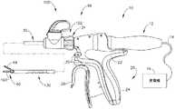
図1は、例示的な超音波手術器具(10)を示す。器具(10)の少なくとも一部は、本明細書で引用する種々の特許、特許出願公開、及び特許出願のうちのいずれかの教示の少なくともいくつかに従って、構築され得、かつ動作可能であり得る。本明細書に記載されるように、また以下にて更に詳細に記載するように、器具(10)は、実質的に同時に、組織を切断し、かつ組織(例えば、血管など)を封止又は接合するように動作可能である。I. Exemplary Ultrasonic Surgical Instruments FIG. 1 shows an exemplary ultrasonic surgical instrument (10). At least a portion of the device (10) may be constructed and operable in accordance with at least some of the teachings of any of the various patents, patent application publications, and patent applications cited herein. .. As described herein, and as described in more detail below, the device (10) cuts the tissue and seals the tissue (eg, blood vessels, etc.) at substantially the same time. It can operate to join.
本実施例の器具(10)は、ハンドルアセンブリ(20)と、シャフトアセンブリ(30)と、エンドエフェクタ(40)と、を含む。ハンドルアセンブリ(20)は、ピストルグリップ(24)と、一対のボタン(26)とを含む本体(22)を含む。ハンドルアセンブリ(20)は、ピストルグリップ(24)へと向かうように、またそれから離れるように枢動可能なトリガ(28)を更に含む。しかしながら、はさみグリップ構成などが挙げられるがこれに限定されない、種々の他の好適な構成が使用され得ることを理解されたい。エンドエフェクタ(40)は、超音波ブレード(160)と枢動クランプアーム(44)とを含む。クランプアーム(44)はトリガ(28)と連結され、これにより、クランプアーム(44)は、ピストルグリップ(24)へと向かうトリガ(28)の枢動に応答して、超音波ブレード(160)に向かって枢動可能となり、また、クランプアーム(44)は、ピストルグリップ(24)から離れる方向へのトリガ(28)の枢動に応答して、超音波ブレード(160)から離れる方向に枢動可能となる。クランプアーム(44)をトリガ(28)と連結させることができる種々の好適な方法は、本明細書の教示を考慮することで当業者には明らかとなるであろう。いくつかの変形形態では、クランプアーム(44)及び/又はトリガ(28)を図1に示す開放位置へと付勢するために、1つ又は2つ以上の弾性部材が使用される。 The instrument (10) of this embodiment includes a handle assembly (20), a shaft assembly (30), and an end effector (40). The handle assembly (20) includes a body (22) that includes a pistol grip (24) and a pair of buttons (26). The handle assembly (20) further includes a trigger (28) that can be pivoted towards and away from the pistol grip (24). However, it should be understood that various other suitable configurations may be used, such as, but not limited to, scissors grip configurations. The end effector (40) includes an ultrasonic blade (160) and a pivot clamp arm (44). The clamp arm (44) is coupled to the trigger (28), which causes the clamp arm (44) to respond to the pivot of the trigger (28) towards the pistol grip (24) with the ultrasonic blade (160). The clamp arm (44) is pivotable towards, and the clamp arm (44) is pivoted away from the ultrasonic blade (160) in response to the pivoting of the trigger (28) away from the pistol grip (24). It becomes possible to move. Various suitable methods by which the clamp arm (44) can be coupled to the trigger (28) will be apparent to those skilled in the art by considering the teachings herein. In some variants, one or more elastic members are used to urge the clamp arm (44) and / or the trigger (28) to the open position shown in FIG.
超音波トランスデューサアセンブリ(12)は、ハンドルアセンブリ(20)の本体(22)から近位に延在する。トランスデューサアセンブリ(12)は、トランスデューサアセンブリ(12)が発電機(16)から電力を受け取るように、ケーブル(14)を介して発電機(16)と連結されている。トランスデューサアセンブリ(12)の圧電素子は、その電力を超音波振動に変換する。発電機(16)は、電源と、トランスデューサアセンブリ(12)による超音波振動の生成に特に適した電力プロファイルをトランスデューサアセンブリ(12)に提供するように構成された制御モジュールと、を含むことができる。ほんの一例として、発電機(16)は、Ethicon Endo−Surgery,Inc.(Cincinnati,Ohio)により販売されているGEN04又はGEN11を含み得る。追加的にあるいは代替え的に、発電機(16)は、2011年4月14日公開の「Surgical Generator for Ultrasonic and Electrosurgical Devices」と題された米国特許出願公開第2011/0087212号の教示の少なくともいくつかに従って構築され得、その開示は、参照により本明細書に組み込まれる。更に、発電機(16)の機能の少なくとも一部がハンドルアセンブリ(20)に組み込まれていてもよく、更に言えば、ハンドルアセンブリ(20)は、ケーブル(14)を省略するために電池又はその他の搭載された電源を含んでもよいことも理解されたい。発電機(16)が取り得る更にその他の好適な形態、並びに発電機(16)が提供し得る種々の特徴及び動作性は、本明細書の教示を考慮することで当業者には明らかとなるであろう。 The ultrasonic transducer assembly (12) extends proximally from the body (22) of the handle assembly (20). The transducer assembly (12) is connected to the generator (16) via a cable (14) so that the transducer assembly (12) receives power from the generator (16). The piezoelectric element of the transducer assembly (12) converts its power into ultrasonic vibrations. The generator (16) can include a power source and a control module configured to provide the transducer assembly (12) with a power profile that is particularly suitable for generating ultrasonic vibrations by the transducer assembly (12). .. As just one example, the generator (16) is available from Ethicon Endo-Surgery, Inc. May include GEN04 or GEN11 sold by (Cincinnati, Ohio). Additional or alternative, the generator (16) is at least some of the teachings of US Patent Application Publication No. 2011/0087212 entitled "Surgical Generator for Ultrasonic and Electrosurgical Devices" published April 14, 2011. It may be constructed in accordance with the above, the disclosure of which is incorporated herein by reference. Further, at least some of the functions of the generator (16) may be incorporated into the handle assembly (20), further the handle assembly (20) is a battery or other to omit the cable (14). It should also be understood that the on-board power supply may be included. Still other suitable embodiments that the generator (16) can take, as well as various features and operability that the generator (16) can provide, will be apparent to those skilled in the art by considering the teachings herein. Will.
A.例示的なエンドエフェクタ及び音響ドライブトレーン
図2〜4で最も良く分かるように、本実施例のエンドエフェクタ(40)は、クランプアーム(44)と超音波ブレード(160)とを含む。クランプアーム(44)は、ブレード(160)に対向してクランプアーム(44)の下側に固定されるクランプパッド(46)を含む。クランプパッド(46)は、ポリテトラフルオロエチレン(PTFE)及び/又は任意の他の好適な材料を含んでもよい。クランプアーム(44)は、遠位外部シース(33)の遠位部分内に固定して取り付けられた上部遠位シャフト要素(172)の遠位突出舌部(43)に枢動可能に固定される。クランプアーム(44)は、クランプアーム(44)とブレード(160)との間に組織を選択的にクランプするために、ブレード(160)に向かって及びブレード(160)から離れる方向に選択的に枢動するように動作可能である。一対のアーム(156)は、クランプアーム(44)から横方向に延在し、遠位外部シース(33)の遠位部分内にスライド可能に配設された、下部遠位シャフト要素(170)に枢動可能に固定される。A. Exemplary End Effectors and Acoustic Drive Trains As best seen in FIGS. 2-4, the end effector (40) of this embodiment includes a clamp arm (44) and an ultrasonic blade (160). The clamp arm (44) includes a clamp pad (46) that faces the blade (160) and is secured underneath the clamp arm (44). The clamp pad (46) may contain polytetrafluoroethylene (PTFE) and / or any other suitable material. The clamp arm (44) is pivotally secured to the distal protruding tongue (43) of the upper distal shaft element (172) fixed and attached within the distal portion of the distal external sheath (33). To. The clamp arm (44) selectively clamps tissue between the clamp arm (44) and the blade (160) toward the blade (160) and away from the blade (160). It can move to move like a pivot. A pair of arms (156) laterally extend from the clamp arm (44) and are slidably disposed within the distal portion of the distal external sheath (33), the lower distal shaft element (170). It is fixed so that it can be pivotally moved.
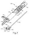
図7〜8で最も良く分かるように、ケーブル(174)は、下部遠位シャフト要素(170)に固定されている。ケーブル(174)は、シャフトアセンブリ(30)の関節運動セクション(130)に対して長手方向に並進して、クランプアーム(44)をブレード(160)に向かって及びそれから離れて選択的に枢動するように動作可能である。具体的には、ケーブル(174)がピストルグリップ(24)に向かうトリガ(28)の枢動に応じて近位に並進し、かつこれによりクランプアーム(44)がピストルグリップ(24)に向かうトリガ(28)の枢動に応じてブレード(160)に向かって枢動するように、ケーブル(174)はトリガ(28)と連結される。加えて、クランプアーム(44)がピストルグリップ(24)から離れるトリガ(28)の枢動に応じてブレード(160)から離れて枢動するように、ケーブル(174)は、ピストルグリップ(24)から離れるトリガ(28)の枢動に応じて遠位に並進する。 As best seen in FIGS. 7-8, the cable (174) is secured to the lower distal shaft element (170). The cable (174) is longitudinally translated relative to the range of motion section (130) of the shaft assembly (30) and selectively pivots the clamp arm (44) towards and away from the blade (160). It is possible to operate as if. Specifically, the cable (174) translates proximally in response to the pivot of the trigger (28) towards the pistol grip (24), which causes the clamp arm (44) to trigger towards the pistol grip (24). The cable (174) is coupled to the trigger (28) so that it pivots towards the blade (160) in response to the pivot of (28). In addition, the cable (174) has the pistol grip (24) so that the clamp arm (44) pivots away from the blade (160) in response to the pivot of the trigger (28) away from the pistol grip (24). Translates distally in response to the pistol of the trigger (28) away from.
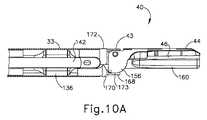
下部遠位シャフト要素(170)は、半円形基部(168)から延在する一対の遠位フランジ(171、173)を含む。フランジ(171、173)は、各々、それぞれの開口部(175、177)を含む。クランプアーム(44)は、一対の内方に延在する一体式ピン(41、45)を介して、下部遠位シャフト要素(170)に回転可能に連結されている。ピン(41、45)は、クランプアーム(44)のアーム(156)から内方に延在し、下部遠位シャフト要素(170)のそれぞれの開口部(175、177)内に回転可能に配設される。図10A〜図10Bで示されるように、ケーブル(174)の長手方向の並進は、近位位置(図10A)と遠位位置(図10B)との間での下部遠位シャフト要素(170)の長手方向の並進を生じさせる。下部遠位シャフト要素(170)の長手方向の並進は、閉鎖位置(図10A)と開放位置(図10B)との間でのクランプアーム(44)の回転を生じさせる。 The lower distal shaft element (170) includes a pair of distal flanges (171, 173) extending from the semicircular base (168). The flanges (171, 173) each include an opening (175, 177). The clamp arm (44) is rotatably connected to the lower distal shaft element (170) via a pair of inwardly extending integral pins (41, 45). Pins (41, 45) extend inward from the arm (156) of the clamp arm (44) and are rotatably located within each opening (175, 177) of the lower distal shaft element (170). Will be set up. As shown in FIGS. 10A-10B, the longitudinal translation of the cable (174) is the lower distal shaft element (170) between the proximal position (FIG. 10A) and the distal position (FIG. 10B). Produces longitudinal translation of. Longitudinal translation of the lower distal shaft element (170) results in rotation of the clamp arm (44) between the closed position (FIG. 10A) and the open position (FIG. 10B).
本実施例のブレード(160)は、特に組織がクランプパッド(46)とブレード(160)との間で圧縮されているときに組織を効果的に切り開いて封止するために、超音波周波数で振動するように動作可能である。ブレード(160)は、トランスデューサアセンブリ(12)と音響導波管(180)とを含む音響ドライブトレーンの遠位端に位置している。音響導波管(180)は、関節運動セクション(130)に関連付けられている可撓性部分(166)を含む。トランスデューサアセンブリ(12)は、電力を超音波振動に変換するように動作可能であり、この超音波振動は、次いで、既知の構成及び技術に従って導波管(180)に沿ってブレード(160)まで伝達される。実施例のみの目的で、音響ドライブトレーンのこの部分は、本明細書に引用される種々の参考文献の種々の教示に従って構成されてもよい。 The blade (160) of this embodiment is at an ultrasonic frequency to effectively cut open and seal the tissue, especially when the tissue is compressed between the clamp pad (46) and the blade (160). It can operate to vibrate. The blade (160) is located at the distal end of the acoustic drive train, which includes the transducer assembly (12) and the acoustic waveguide (180). The acoustic waveguide (180) includes a flexible portion (166) associated with the joint motion section (130). The transducer assembly (12) is capable of operating to convert power into ultrasonic vibrations, which are then subjected to blades (160) along the waveguide (180) according to known configurations and techniques. Be transmitted. For purposes of embodiments only, this portion of the acoustic drive train may be configured according to the various teachings of the various references cited herein.
図3で最も良く分かるように、導波管(180)の可撓性部分(166)は、遠位フランジ(136)と、近位フランジ(138)と、これらフランジ(136、138)間に位置する狭窄セクション(164)と、を含む。本実施例では、フランジ(136、138)は、導波管(180)の可撓性部分(166)を介して伝達される共鳴超音波振動に関連したノードに対応する位置(すなわち、振動振幅が最小となる位置)に位置する。狭窄セクション(164)は、導波管(180)の可撓性部分(166)の超音波振動を伝達する能力に顕著な影響を与えることなく、導波管(180)の可撓性部分(166)が屈曲することを可能にするように構成される。ほんの一例として、狭窄化セクション(164)は、その開示が参照により本明細書に組み込まれる、米国特許出願公開第2014/0005701号及び同第2014/0114334号の1つ又は2つ以上の教示に従って構成され得る。導波管(180)がトランスデューサアセンブリ(12)と機械的かつ音響的に連結され得る種々の好適な方法は、本明細書の教示を考慮することで当業者には明らかとなるであろう。 As best seen in FIG. 3, the flexible portion (166) of the waveguide (180) is located between the distal flange (136), the proximal flange (138) and these flanges (136, 138). Includes a located constriction section (164). In this embodiment, the flange (136, 138) is located at a position (ie, vibration amplitude) corresponding to the node associated with the resonant ultrasonic vibration transmitted through the flexible portion (166) of the waveguide (180). Is located at the minimum position). The constriction section (164) does not significantly affect the ability of the flexible portion (166) of the waveguide (180) to transmit ultrasonic vibrations, and the flexible portion (180) of the waveguide (180). 166) is configured to allow bending. As just one example, the stenosis section (164) is in accordance with one or more of the teachings of U.S. Patent Application Publication Nos. 2014/0005701 and 2014/0114334, the disclosure of which is incorporated herein by reference. Can be configured. Various suitable methods by which the waveguide (180) can be mechanically and acoustically coupled to the transducer assembly (12) will be apparent to those of skill in the art by considering the teachings herein.
当業者であれば、物理学の問題として、ブレード(24)の遠位端が、導波管(28)を介して伝達される共鳴超音波振動に関連したアンチノードに対応する位置(すなわち、音響アンチノード)に位置することを理解するであろう。トランスデューサアセンブリ(12)が通電されると、ブレード(160)の遠位端は、例えば、ピーク間で約10〜500マイクロメートル、場合によっては、例えば、55.5kHzの所定の振動周波数foで約20〜約200マイクロメートルの範囲で長手方向に移動するように構成される。ブレード(160)とクランプパッド(46)との間で組織が圧縮されると、ブレード(160)の超音波振動が、組織の切断と、隣接した組織細胞内のタンパク質の変性とを同時に行い得、それにより比較的小さい熱拡散で凝固効果が提供される。For those skilled in the art, as a matter of physics, the position where the distal end of the blade (24) corresponds to the antinode associated with the resonant ultrasonic vibration transmitted through the waveguide (28) (ie, ie). You will understand that it is located in the acoustic antinode). When the transducer assembly (12) is energized, the distal end of the blade (160), for example, about 10 to 500 microns peak-to-peak, in some cases, for example, at a predetermined vibration frequencyf o of 55.5kHz It is configured to move longitudinally in the range of about 20 to about 200 micrometers. When the tissue is compressed between the blade (160) and the clamp pad (46), ultrasonic vibrations of the blade (160) can simultaneously cleave the tissue and denature proteins in adjacent histiocytes. , Thereby providing a coagulation effect with relatively small heat diffusion.
いくつかの変形形態では、エンドエフェクタ(40)は、組織に超音波エネルギーを印加する以外に、組織に高周波(RF)電気外科エネルギーを印加するように動作可能である。ほんの一例として、エンドエフェクタ(40)は、その開示が参照により本明細書に組み込まれる、2015年5月21日公開の「Ultrasonic Surgical Instrument with Electrosurgical Feature」と題された米国特許出願公開第2015/0141981号、及びその開示が参照により本明細書に組み込まれる、2014年3月4日発行の「Ultrasonic Electrosurgical Instruments」と題された米国特許第8,663,220号の教示の少なくともいくつかに従って構成され得、かつ動作可能であり得る。音響伝達アセンブリ及びトランスデューサアセンブリ(12)に関する他の好適な構成は、本明細書の教示を考慮することで当業者には明らかとなるであろう。同様に、エンドエフェクタ(40)の他の好適な構成も、本明細書の教示を考慮することで当業者には明らかとなるであろう。 In some variants, the end effector (40) can behave to apply radio frequency (RF) electrosurgical energy to the tissue in addition to applying ultrasonic energy to the tissue. As just one example, the End Effector (40) is a U.S. Patent Application Publication No. 2015 / entitled "Ultrasonic Structural Instrument with Electrical Feature" published May 21, 2015, the disclosure of which is incorporated herein by reference. Constructed in accordance with at least some of the teachings of US Pat. No. 8,663,220, entitled "Ultrasonic Electrical Instruments," issued March 4, 2014, which is incorporated herein by reference to 0141981 and its disclosure. And can be operational. Other suitable configurations for the acoustic transmission assembly and the transducer assembly (12) will be apparent to those of skill in the art by considering the teachings herein. Similarly, other suitable configurations of the end effector (40) will be apparent to those of skill in the art by considering the teachings herein.
B.例示的なシャフトアセンブリ及び関節運動セクション
本実施例のシャフトアセンブリ(30)は、ハンドルアセンブリ(20)から遠位に延在する。図2〜7で示されるように、シャフトアセンブリ(30)は、クランプアーム(44)駆動機構及び上記の音響伝送機構を囲む、遠位外部シース(33)及び近位外部シース(32)を含む。シャフトアセンブリ(30)は、シャフトアセンブリ(30)の遠位部分に位置する関節運動セクション(130)を更に含み、エンドエフェクタ(40)は関節運動セクション(130)より遠位に位置する。図1に示すように、回転制御アセンブリ(102)は、回転制御ノブ(31)の形態の回転制御部材を有し、この回転制御ノブ(31)は、近位外部シース(32)の近位部分に固定される。ノブ(31)は本体(22)に対して回転可能であるので、シャフトアセンブリ(30)は、外部シース(32)によって画定される長手方向軸線を中心に、ハンドルアセンブリ(20)に対して回転可能である。かかる回転は、エンドエフェクタ(40)、関節運動セクション(130)、及びシャフトアセンブリ(30)の一体的回転を提供することができる。当然のことながら、回転可能特徴部は、所望により、単に省略されてもよい。B. Exemplary Shaft Assembly and Range of Motion Section The shaft assembly (30) of this embodiment extends distally from the handle assembly (20). As shown in FIGS. 2-7, the shaft assembly (30) includes a distal external sheath (33) and a proximal external sheath (32) that surround the clamp arm (44) drive mechanism and the acoustic transmission mechanism described above. .. The shaft assembly (30) further includes a range of motion section (130) located distal to the shaft assembly (30), and the end effector (40) is located distal to the range of motion section (130). As shown in FIG. 1, the rotation control assembly (102) has a rotation control member in the form of a rotation control knob (31), which rotation control knob (31) is proximal to the proximal external sheath (32). It is fixed to the part. Since the knob (31) is rotatable with respect to the body (22), the shaft assembly (30) rotates about the longitudinal axis defined by the external sheath (32) with respect to the handle assembly (20). It is possible. Such rotation can provide an integral rotation of the end effector (40), the range of motion section (130), and the shaft assembly (30). Of course, the rotatable features may be simply omitted, if desired.
関節運動セクション(130)は、外部シース(32)によって画定される長手方向軸線に対して種々の横方向偏向角度にてエンドエフェクタ(40)を選択的に位置付けるように動作可能である。関節運動セクション(130)は、様々な形態を取ることができる。ほんの一例として、関節運動セクション(130)は、本明細書において、参照することにより組み込まれる米国公開特許第2012/0078247号の1つ又は2つ以上の教示に従って構成することができる。別のあくまで例示的な例として、関節運動セクション(130)は、それらの開示が参照により本明細書に組み込まれる、米国特許出願公開第2014/0005701号、及び/又は米国特許出願公開第2014/0114334号の1つ又は2つ以上の教示に従って構成され得る。関節運動セクション(130)が取り得る種々の他の好適な形態が、本明細書の教示を考慮することで当業者に明らかとなるであろう。 The range of motion section (130) can operate to selectively position the end effector (40) at various lateral deflection angles with respect to the longitudinal axis defined by the external sheath (32). The range of motion section (130) can take various forms. As just one example, the range of motion section (130) can be configured according to one or more of the teachings of US Publication No. 2012/0078247 incorporated herein by reference. As another exemplary example, the Joint Movement Section (130) is described in U.S. Patent Application Publication No. 2014/0005701 and / or U.S. Patent Application Publication No. 2014 /, wherein their disclosure is incorporated herein by reference. It may be configured according to one or more of the teachings of 0114334. Various other suitable forms that the range of motion section (130) can take will be apparent to those of skill in the art by considering the teachings herein.
図2〜6Bで最も良く分かるように、この実施例の関節運動セクション(130)は、一組の3つの保持カラー(133)及び一対のリブ付き本体部分(132、134)を含み、一対の関節運動バンド(140、142)が保持カラー(133)の内面とリブ付き本体部分(132、134)の外面との間に画定されるそれぞれのチャネル(135、137)に沿って延在する。リブ付き本体部分(132、134)は、導波管(180)の可撓性部分(166)のフランジ(136、138)間に長手方向に位置付けられる。関節運動セクション(130)が関節運動状態を達成するために屈曲する場合、リブ付き本体部分(132、134)は導波管(180)の可撓性部分(166)で屈曲するように構成される。 As best seen in FIGS. 2-6B, the range of motion section (130) of this embodiment comprises a pair of three retaining collars (133) and a pair of ribbed body portions (132, 134). The range of motion bands (140, 142) extend along the respective channels (135, 137) defined between the inner surface of the retaining collar (133) and the outer surface of the ribbed body portion (132, 134). The ribbed body portions (132, 134) are longitudinally positioned between the flanges (136, 138) of the flexible portion (166) of the waveguide (180). When the joint motion section (130) bends to achieve a joint motion state, the ribbed body portions (132, 134) are configured to bend at the flexible portion (166) of the waveguide (180). To.
図3は、リブ付き本体部分(132、134)をより詳細に示す。リブ付き本体部分(132)は、リブ付き本体部分(132)の横方向屈曲を促進するように構成されている、一組の3つのリブ(150)を含む。リブ付き本体部分(132)はまた、関節運動バンド(140)をリブ付き本体部分(132)に対してスライド可能にしながら、関節運動バンド(140)を受容するように構成されている、チャネル(135)も画定する。同様に、リブ付き本体部分(134)は、リブ付き本体部分(134)の横方向屈曲を促進するように構成されている、一組の3つのリブ(152)を含む。当然のことながら、任意の他の好適な数のリブ(150、152)が設けられてもよい。リブ付き本体部分(134)はまた、関節運動バンド(142)をリブ付き本体部分(137)に対してスライド可能にしながら、関節運動バンド(142)を受容するように構成されている、チャネル(137)も画定する。 FIG. 3 shows the ribbed body portions (132, 134) in more detail. The ribbed body portion (132) includes a set of three ribs (150) configured to facilitate lateral bending of the ribbed body portion (132). The ribbed body portion (132) is also configured to receive the joint motion band (140) while allowing the joint motion band (140) to slide relative to the ribbed body portion (132). 135) is also defined. Similarly, the ribbed body portion (134) includes a set of three ribs (152) configured to facilitate lateral bending of the ribbed body portion (134). Of course, any other suitable number of ribs (150, 152) may be provided. The ribbed body portion (134) is also configured to receive the joint motion band (142) while allowing the joint motion band (142) to slide relative to the ribbed body portion (137). 137) is also defined.
図5で最も良く分かるように、リブ付き本体部分(132、134)は、関節運動バンド(140、142)と導波管(180)の可撓性部分(166)との間に横方向に介在する。リブ付き本体部分(132、134)は、導波管(180)に接触せずに導波管(180)の可撓性部分(166)を収容するようにサイズ決定される内部通路を共に画定するように、互いに嵌合する。加えて、リブ付き本体部分(132、134)が互いに結合されるとき、リブ付き本体部分(132、134)内に形成される一対の相補的な遠位ノッチ(131A、131B)が整列して、遠位外部シース(33)の内方に突出する一対の弾性タブ(38)を受容する。タブ(38)とノッチ(131A、131B)との間のこの係合は、遠位外部シース(33)に対してリブ付き本体部分(132、134)を長手方向に固定する。同様に、リブ付き本体部分(132、134)が互いに結合されるとき、リブ付き本体部分(132、134)内に形成される一対の相補的な近位ノッチ(139A、139B)が整列して、近位外部シース(32)の内方に突出する一対の弾性タブ(37)を受容する。タブ(37)とノッチ(139A、139B)との間のこの係合は、近位外部シース(32)に対してリブ付き本体部分(132、134)を長手方向に固定する。当然のことながら、任意の他の好適な種類の特徴部を使用して、リブ付き本体部分(132、134)を近位外部シース(32)及び/又は遠位外部シース(33)と結合することができる。 As best seen in FIG. 5, the ribbed body portion (132, 134) is laterally located between the joint motion band (140, 142) and the flexible portion (166) of the waveguide (180). Intervene. The ribbed body portions (132, 134) together define an internal passage that is sized to accommodate the flexible portion (166) of the waveguide (180) without contacting the waveguide (180). Fit to each other so that they do. In addition, when the ribbed body portions (132, 134) are coupled to each other, a pair of complementary distal notches (131A, 131B) formed within the ribbed body portions (132, 134) are aligned. , Receiving a pair of elastic tabs (38) that project inwardly from the distal external sheath (33). This engagement between the tab (38) and the notch (131A, 131B) longitudinally secures the ribbed body portion (132, 134) to the distal external sheath (33). Similarly, when the ribbed body portions (132, 134) are joined together, a pair of complementary proximal notches (139A, 139B) formed within the ribbed body portions (132, 134) are aligned. , Receiving a pair of elastic tabs (37) protruding inward of the proximal outer sheath (32). This engagement between the tab (37) and the notch (139A, 139B) longitudinally secures the ribbed body portions (132, 134) to the proximal external sheath (32). Not surprisingly, the ribbed body portions (132, 134) are coupled to the proximal external sheath (32) and / or the distal external sheath (33) using any other suitable type of feature. be able to.
関節運動バンド(140、142)の遠位端は、上部遠位シャフト要素(172)に一体型に固定される。関節運動バンド(140、142)が長手方向反対向きに並進するとき、これは、関節運動セクション(130)を屈曲させ、それによって、エンドエフェクタ(40)を、図6Aに示される真っ直ぐな構成から図6Bに示される関節運動した構成に、シャフトアセンブリ(30)の長手方向軸線から離れて横方向に偏向させる。具体的には、エンドエフェクタ(40)は、近位に引かれている関節運動バンド(140、142)の方に関節運動することになる。かかる関節運動中、他方の関節運動バンド(140、142)は、上部遠位シャフト要素(172)によって遠位に引かれ得る。代替的に、他方の関節運動バンド(140、142)は、関節運動制御によって遠位に駆動されてもよい。リブ付き本体部分(132、134)及び狭窄セクション(164)はすべて、エンドエフェクタ(40)の上記の関節運動に対応するのに十分に可撓性である。更に、可撓性音響導波管(166)は、関節運動セクション(130)が、図6Bに示されるような関節運動状態にあるときでも、導波管(180)からブレード(160)に超音波振動を効率的に伝達するように構成される。 The distal end of the range of motion bands (140, 142) is integrally secured to the upper distal shaft element (172). When the range of motion bands (140, 142) translate in the opposite longitudinal direction, this bends the range of motion section (130), thereby causing the end effector (40) from the straight configuration shown in FIG. 6A. The articulated configuration shown in FIG. 6B is laterally deflected away from the longitudinal axis of the shaft assembly (30). Specifically, the end effector (40) will move toward the proximally pulled range of motion bands (140, 142). During such range of motion, the other range of motion bands (140, 142) can be pulled distally by the upper distal shaft element (172). Alternatively, the other range of motion bands (140, 142) may be driven distally by range of motion control. The ribbed body portions (132, 134) and the stenosis section (164) are all flexible enough to accommodate the above-mentioned range of motion of the end effector (40). Further, the flexible acoustic waveguide (166) extends from the waveguide (180) to the blade (160) even when the joint motion section (130) is in the joint motion state as shown in FIG. 6B. It is configured to efficiently transmit ultrasonic vibrations.
図3で最も良く分かるように、導波管(180)の各フランジ(136、138)は、それぞれの対の対向する平面(192、196)を含む。平面(192、196)は、可撓性部分(166)の狭窄セクション(164)を通って延在する垂直面に平行である垂直面に沿って配向される。平面(192、196)は、関節運動バンド(140、142)のための隙間を提供するように構成されている。具体的には、近位フランジ(138)の平面(196)は、近位フランジ(138)と近位外部シース(32)の内径との間に関節運動バンド(140、142)を収容し、一方、遠位フランジ(136)の平面(192)は、遠位フランジ(136)と遠位外部シース(33)の内径との間に関節運動バンド(140、142)を収容する。当然のことながら、平面(192、196)は、任意の好適な種類の断面(例えば、正方形、平面、円形など)を有する、スロット、チャネルなどが挙げられるが、これらに限定されない様々な特徴部で置き換えることができる。導波管(180)は、その開示が、本明細書において、参照することにより組み込まれる、2013年4月23日出願の米国公開第2013/0289592号、発明の名称「Ultrasonic Device for Cutting and Coagulating」の教示の少なくともいくつかに従って形成される平面を含んでよいことも理解されたい。 As best seen in FIG. 3, each flange (136, 138) of the waveguide (180) comprises a pair of opposite planes (192, 196). The plane (192, 196) is oriented along a vertical plane parallel to the vertical plane extending through the constricted section (164) of the flexible portion (166). The plane (192, 196) is configured to provide a gap for the range of motion bands (140, 142). Specifically, the plane (196) of the proximal flange (138) accommodates the joint motion band (140, 142) between the proximal flange (138) and the inner diameter of the proximal external sheath (32). On the other hand, the plane (192) of the distal flange (136) accommodates the articular movement band (140, 142) between the distal flange (136) and the inner diameter of the distal external sheath (33). Of course, the plane (192, 196) includes, but is not limited to, various features such as slots, channels, etc. having any suitable type of cross section (eg, square, plane, circle, etc.). Can be replaced with. The waveguide (180) is incorporated herein by reference in US Publication No. 2013/0289592, filed April 23, 2013, entitled "Ultrasonic Device for Cutting and Coagulating." It should also be understood that it may include planes formed according to at least some of the teachings of.
本実施例では、外側リング(133)は、3つのリング(133)が3つのリブ(150、152)に対してもたらされるように、リブ(150、152)に対応する長手方向位置に位置付けられる。関節運動バンド(140)は、リング(133)とリブ付き本体部分(132)との間のチャネル(135)内に横方向に介在し、一方、関節運動バンド(142)は、リング(133)とリブ付き本体部分(134)との間のチャネル(137)内に横方向に介在する。リング(133)は、特に関節運動セクション(130)が(例えば、図6Bに示される構成と類似の)屈曲構成にあるとき、関節運動バンド(140、142)を平行関係に維持するように構成されている。換言すれば、関節運動バンド(140)が、屈曲した関節運動セクション(130)によって呈される曲線形状の内径上にあるとき、リング(133)は、関節運動バンド(140)が、関節運動バンド(142)が続く曲線状経路を補完する曲線状経路に続くように、関節運動バンド(140)を保持することができる。チャネル(135、137)は、リブ付き本体部分(150、152)に固定されているリング(133)を伴ってさえも、関節運動バンド(140、142)が、関節運動セクション(130)を通って、依然として自由にスライドすることができるように、それぞれの関節運動バンド(140、142)を収容するようにサイズ決定されることを理解されたい。リング(133)は、締まり嵌め、接着、溶接などが挙げられるが、これらに限定されない種々の方法で、リブ付き本体部分(132、134)に固定され得ることも理解されたい。 In this embodiment, the outer ring (133) is positioned in the longitudinal position corresponding to the ribs (150, 152) such that the three rings (133) are brought to the three ribs (150, 152). .. The range of motion band (140) is laterally interposed in the channel (135) between the ring (133) and the ribbed body portion (132), while the range of motion band (142) is the ring (133). Laterally intervening in the channel (137) between the ribbed body portion (134). The ring (133) is configured to maintain the range of motion bands (140, 142) in parallel, especially when the range of motion section (130) is in a flexion configuration (eg, similar to the configuration shown in FIG. 6B). Has been done. In other words, when the range of motion band (140) is on the inner diameter of the curve presented by the flexed range of motion section (130), the ring (133) is the range of motion band (140). The range of motion band (140) can be retained so as to follow a curved path that complements the curved path followed by (142). The channel (135, 137) has the range of motion band (140, 142) passing through the range of motion section (130), even with the ring (133) secured to the ribbed body portion (150, 152). It should be understood that they are sized to accommodate the respective range of motion bands (140, 142) so that they can still slide freely. It should also be appreciated that the ring (133) can be secured to the ribbed body portions (132, 134) by various methods including, but not limited to, tight fitting, gluing, welding and the like.
関節運動バンド(140、142)が長手方向反対向きに並進するとき、モーメントが生まれ、上部遠位シャフト要素(172)を介して遠位外部シース(33)の遠位端に適用される。これによって、関節運動バンド(140、142)の軸方向の力を導波管(180)に伝えることなく、導波管(180)の可撓性部分(166)の関節運動セクション(130)及び狭窄セクション(164)に関節運動させる。 When the range of motion bands (140, 142) translate in the opposite longitudinal direction, a moment is generated and applied to the distal end of the distal external sheath (33) via the upper distal shaft element (172). Thereby, the joint motion section (130) of the flexible portion (166) of the waveguide (180) and the joint motion section (130) of the flexible portion (166) of the waveguide (180) without transmitting the axial force of the joint motion band (140, 142) to the waveguide (180). Joint exercise is performed on the narrowed section (164).
図9で最も良く分かるように、関節運動制御アセンブリ(100)は、外部シース(32)の近位部分に固定されている。関節運動制御アセンブリ(100)は、ハウジング(110)と、回転可能な関節運動制御ノブ(120)と、を含む。図示され、かつ本明細書に記載されるように、関節運動制御アセンブリ(100)及び回転制御アセンブリ(102)は、全体としてシャフト制御アセンブリ(98)を画定する。ハウジング(110)は、一対の垂直に交差する円筒形部分(112、114)を含む。ノブ(120)は、ノブ(120)がハウジング(110)の円筒形部分(112)内で回転するように動作可能であるように、ハウジング(110)の第1の中空円筒形部分(112)内に回転可能に配設される。シャフトアセンブリ(30)は、第2の中空の円筒形部分(114)内にスライド可能かつ回転可能に配設される。シャフトアセンブリ(30)は一対の並進可能部材(161、162)を含むが、これらの両方とも、外部シース(32)の近位部分を通ってスライド可能に長手方向に延在する。並進可能部材(161、162)は、遠位位置と近位位置との間の第2の円筒形部分(114)内で長手方向に並進可能である。並進可能部材(161、162)は、並進可能部材(161)の長手方向の並進が関節運動バンド(140)の長手方向の並進をもたらすように、かつ並進可能部材(162)の長手方向の並進が関節運動バンド(142)の長手方向の並進をもたらすように、それぞれの関節運動バンド(140、142)と機械的に結合される。 As best seen in FIG. 9, the joint motion control assembly (100) is secured to the proximal portion of the external sheath (32). The joint motion control assembly (100) includes a housing (110) and a rotatable joint motion control knob (120). As illustrated and described herein, the joint motion control assembly (100) and the rotation control assembly (102) together define the shaft control assembly (98). The housing (110) includes a pair of vertically intersecting cylindrical portions (112, 114). The knob (120) has a first hollow cylindrical portion (112) of the housing (110) such that the knob (120) can operate to rotate within the cylindrical portion (112) of the housing (110). It is rotatably arranged inside. The shaft assembly (30) is slidably and rotatably disposed within a second hollow cylindrical portion (114). The shaft assembly (30) includes a pair of translatable members (161, 162), both of which extend longitudinally slidably through the proximal portion of the outer sheath (32). The translatable member (161, 162) is longitudinally translatable within a second cylindrical portion (114) between the distal and proximal positions. The translatable member (161, 162) is such that the longitudinal translation of the translatable member (161) results in the longitudinal translation of the joint motion band (140) and the longitudinal translation of the translatable member (162). Is mechanically coupled to the respective joint motion bands (140, 142) so as to result in longitudinal translation of the joint motion bands (142).
ノブ(120)は、ノブ(120)の底面から下方に延在する一対のピン(122、124)を含む。ピン(122、124)はハウジング(110)の第2の円筒形部分(114)内に延在し、並進可能部材(161、162)の上面に形成されたそれぞれの一対のチャネル(163A、163B)内に回転可能かつスライド可能に配設される。チャネル(163A、163B)は、ノブ(120)の回転軸の両側に位置付けられ、これにより、ノブ(120)をその回転軸を中心に回転させると、並進可能部材(161、162)はそれぞれ長手方向逆向きに並進する。例えば、第1の方向へのノブ(120)の回転は、並進可能部材(161)及び関節運動バンド(140)の遠位長手方向の並進、並びに並進可能部材(162)及び関節運動バンド(142)の近位長手方向の並進をもたらし、第2の方向へのノブ(120)の回転は、並進可能部材(161)及び関節運動バンド(140)の近位長手方向の並進、並びに並進可能部材(162)及び関節運動バンド(142)の遠位長手方向の並進をもたらす。このため、回転ノブ(120)の回転は、関節運動セクション(130)の関節運動をもたらすことを理解されたい。 The knob (120) includes a pair of pins (122, 124) extending downward from the bottom surface of the knob (120). The pins (122, 124) extend within the second cylindrical portion (114) of the housing (110) and each pair of channels (163A, 163B) formed on the top surface of the translatable member (161, 162). ) Is rotatable and slidable. Channels (163A, 163B) are located on either side of the axis of rotation of the knob (120) so that when the knob (120) is rotated about its axis of rotation, the translatable members (161, 162) are longitudinal, respectively. Translate in the opposite direction. For example, rotation of the knob (120) in the first direction translates in the distal longitudinal direction of the translatable member (161) and the articulatory band (140), as well as the translatable member (162) and the articulatory band (142). ) Proximal longitudinal translation, the rotation of the knob (120) in the second direction is the proximal longitudinal translation of the translatable member (161) and the joint motion band (140), as well as the translatable member. It results in a distal longitudinal translation of (162) and the articular movement band (142). Therefore, it should be understood that the rotation of the rotary knob (120) results in the joint motion of the range of motion section (130).
関節運動制御アセンブリ(100)のハウジング(110)は、第1の円筒形部分(112)の内面から内方に延在する一対の止めネジ(111、113)を含む。ノブ(120)は、ハウジング(110)の第1の円筒形部分(112)内に回転可能に配設され、止めネジ(111、113)は、ノブ(120)内に形成された一対の弓状チャネル(121、123)内にスライド可能に配設される。このため、ノブ(120)の回転はチャネル(121、123)内の止めネジ(111、113)の移動により制限されることを理解されたい。また、止めネジ(111、113)は、ハウジング(110)内にノブ(120)を保持し、ノブ(120)がハウジング(110)の第1の円筒形部分(112)内で垂直に移動することを防止する。 The housing (110) of the joint motion control assembly (100) includes a pair of set screws (111, 113) extending inward from the inner surface of the first cylindrical portion (112). The knob (120) is rotatably disposed within the first cylindrical portion (112) of the housing (110) and the set screw (111, 113) is a pair of bows formed within the knob (120). It is slidably arranged in the shape channel (121, 123). Therefore, it should be understood that the rotation of the knob (120) is limited by the movement of the set screw (111, 113) within the channel (121, 123). Also, the set screws (111, 113) hold the knob (120) in the housing (110) and the knob (120) moves vertically within the first cylindrical portion (112) of the housing (110). To prevent that.
ハウジング(110)の第1の円筒形部分(112)の内面は、第1の円筒形部分(112)の内面内に形成された第1の歯群角度付き配列(116)及び第2の歯群角度付き配列(118)を含む。回転ノブ(120)は、第1の円筒形部分(112)の歯群(116、118)に戻り止めの関係で係合し、それによって、ノブ(120)を特定の回転位置に選択的にロックするように構成された、一対の外方に延出する係合部材(126、128)を含む。係合部材(126、128)と歯群(116、118)との係合は、使用者がノブ(120)に十分な回転力を付与することによって克服され得るが、かかる力がない場合、この係合は、関節運動セクション(130)の真っ直ぐな構成又は関節運動した構成を維持するのに十分である。したがって、ノブ(120)を特定の回転位置に選択的にロックする能力により、操作者は、外部シース(32)によって画定される長手方向軸線に対して、特定の偏向位置に、関節運動セクション(130)を選択的にロックすることができることを理解されたい。 The inner surface of the first cylindrical portion (112) of the housing (110) is the first tooth group angled array (116) and the second tooth formed within the inner surface of the first cylindrical portion (112). Includes group angled array (118). The rotary knob (120) engages the teeth group (116, 118) of the first cylindrical portion (112) in a detent relationship, thereby selectively moving the knob (120) to a particular rotational position. Includes a pair of outwardly extending engaging members (126, 128) configured to lock. The engagement between the engaging member (126, 128) and the tooth group (116, 118) can be overcome by the user applying sufficient rotational force to the knob (120), but in the absence of such force. This engagement is sufficient to maintain a straight or articulated configuration of the articulated section (130). Thus, the ability to selectively lock the knob (120) to a particular rotational position allows the operator to place the joint motion section (120) at a particular deflection position with respect to the longitudinal axis defined by the external sheath (32). It should be understood that 130) can be selectively locked.
器具(10)のいくつかの変形例では、シャフトアセンブリ(30)が真っ直ぐな(非関節運動)構成にある場合、シャフトアセンブリ(30)の関節運動セクション(130)は、シャフトアセンブリ(30)の長手方向軸線に対して最大約15°〜約30°の関節運動角度を達成するように動作可能である。代替的に、関節運動セクション(130)は、任意の他の好適な関節運動角度を達成するように動作可能であってもよい。 In some variants of the instrument (10), if the shaft assembly (30) is in a straight (non-joint motion) configuration, the range of motion section (130) of the shaft assembly (30) is that of the shaft assembly (30). It can operate to achieve a range of motion angles of up to about 15 ° to about 30 ° with respect to the longitudinal axis. Alternatively, the range of motion section (130) may be operable to achieve any other suitable range of motion angle.
II.デュアルモード関節運動制御アセンブリを有する例示的なシャフト制御アセンブリ
関節運動セクション(130)の関節運動を様々な入力感度で駆動するように動作可能なデュアルモード関節運動制御アセンブリを提供することが望ましい場合がある。いくつかの例において、操作者は、比較的大きな程度の関節運動セクション(130)の関節運動を、比較的低い入力感度で迅速にもたらすことを望む場合がある(例えば、エンドエフェクタ(40)の位置決めの精度及び/又は正確さが低くなる)。いくつかの他の例では、操作者は、関節運動の微調整を、比較的高い入力感度でもたらすことを望む場合がある(例えば、エンドエフェクタ(40)の位置決めの精度及び/又は正確さがより高くなる)。以下の説明は、デュアルモード関節運動制御アセンブリ(218)を有する例示的な超音波手術器具(210)に関し、このデュアルモード関節運動制御アセンブリ(218)は、シャフトアセンブリ(216)の関節運動の制御を改善するために、異なる高変速比及び低変速比を有する少なくとも2つの関節運動制御部材(222、223)を含む。以下に記載する違いを除き、この実施例の器具(210)は、上記に述べた器具(10)と同様に構成され、動作可能である。II. Illustrative Shaft Control Assembly with Dual Mode Joint Motion Control Assembly It may be desirable to provide a dual mode joint motion control assembly that can operate to drive the joint motion of the joint motion section (130) with various input sensitivities. be. In some examples, the operator may wish to rapidly bring about a relatively large degree of joint motion in the range of motion section (130) with relatively low input sensitivity (eg, of the end effector (40)). Positioning accuracy and / or accuracy is reduced). In some other examples, the operator may wish to provide fine-tuning of joint motion with relatively high input sensitivity (eg, the accuracy and / or accuracy of positioning the end effector (40)). Will be higher). The following description relates to an exemplary ultrasonic surgical instrument (210) having a dual-mode joint motion control assembly (218), wherein the dual-mode joint motion control assembly (218) controls the joint motion of the shaft assembly (216). Includes at least two joint motion control members (222, 223) with different high and low gear ratios to improve. Except for the differences described below, the instrument (210) of this embodiment is configured and operational in the same manner as the instrument (10) described above.
図11〜図12に示すように、本実施例の器具(210)は、シャフトアセンブリ(212)と、ハンドルアセンブリ(214)と、エンドエフェクタ(40)と、これらに沿って延在する音響導波管(80)と、を更に含む。上述のように、音響導波管(80)は、発電機(16)及びシャフトアセンブリ(212)に動作可能に接続されており、シャフトアセンブリ(212)は、外科手技中にエンドエフェクタ(40)を位置決めするための関節運動セクション(130)を含んでいる。このため、手術器具(210)は、シャフトアセンブリ(212)を長手方向軸線の周りで回転させ、かつ関節運動セクション(130)を関節運動させるように構成されたシャフト制御アセンブリ(216)を備えている。より詳細には、シャフト制御アセンブリ(216)は、関節運動セクション(130)に動作可能に接続された関節運動制御アセンブリ(218)と、シャフトアセンブリ(212)に動作可能に接続された回転制御アセンブリ(220)と、を含む。関節運動制御アセンブリ(218)は、高位の(high)関節運動制御部材(222)と、低位の(low)関節運動制御部材(223)と、を含む。回転制御アセンブリは回転制御部材(224)を含む。関節運動制御アセンブリ(218)は更に、高いギヤ比の駆動部(227)(図14参照)と低いギヤ比の駆動部(228)(図14参照)とを有する変速機アセンブリ(226)を含み、これら駆動部は、2つの異なる入力感度で関節運動セクション(130)を屈曲させるために、高位及び低位の関節運動制御部材(222、223)の選択的操作をシャフトアセンブリ(212)にそれぞれ伝達するように構成されている。 As shown in FIGS. 11-12, the instrument (210) of this embodiment includes a shaft assembly (212), a handle assembly (214), an end effector (40), and an acoustic waveguide extending along them. Also includes a waveguide (80). As mentioned above, the acoustic waveguide (80) is operably connected to the generator (16) and the shaft assembly (212), which is the end effector (40) during the surgical procedure. Includes a range of motion section (130) for positioning. For this reason, the surgical instrument (210) comprises a shaft control assembly (216) configured to rotate the shaft assembly (212) around the longitudinal axis and to joint the joint motion section (130). There is. More specifically, the shaft control assembly (216) includes a joint motion control assembly (218) operably connected to the joint motion section (130) and a rotation control assembly operably connected to the shaft assembly (212). (220) and. The joint motion control assembly (218) includes a high (high) joint motion control member (222) and a low (low) joint motion control member (223). The rotation control assembly includes a rotation control member (224). The joint motion control assembly (218) further includes a transmission assembly (226) having a high gear ratio drive unit (227) (see FIG. 14) and a low gear ratio drive unit (228) (see FIG. 14). , These drives transmit the selective operation of the high and low joint motion control members (222, 223) to the shaft assembly (212), respectively, to flex the joint motion section (130) with two different input sensitivities. It is configured to do.
シャフト制御アセンブリ(216)の遠位部分は、シャフトアセンブリ(212)の近位部分に沿って延在する。シャフト制御アセンブリ(216)の近位部分は、手術器具(210)の使い捨てアセンブリ(230)内に収容される。使い捨てアセンブリ(230)は、ハンドルアセンブリ(214)と取り外し可能に接続して手術器具(210)を形成するように構成されている。ほんの一例として、ハンドルアセンブリ(214)は、その開示が全体として参照により本明細書に組み込まれる、2015年9月25日出願の「Ultrasonic Surgical Instrument with Removable Handle Assembly」と題された米国特許出願第14/868,574号の教示の少なくともいくつかに従って構成され得、かつ動作可能であり得る。更に単なる例として、アセンブリ(214、230)は、その開示が全体として参照により本明細書に組み込まれる、2015年9月25日出願の「Ultrasonic Surgical Instrument with Removable Handle Assembly」と題された米国特許出願第14/868,574号の教示の少なくともいくつかに従って連結させる(及び連結解除させる)ことができる。あるいは、アセンブリ(214、230)は、任意の他の好適な方法で連結(及び連結解除)させてもよい。いくつかの他の変形形態では、器具(210)は、分離可能なアセンブリ(214、230)なしで構築される。例えば、器具(210)は、代わりに、関節運動制御アセンブリ(218)を関節運動制御アセンブリ(100)に替えて、器具(10)と同様に構築されてもよい。 The distal portion of the shaft control assembly (216) extends along the proximal portion of the shaft assembly (212). The proximal portion of the shaft control assembly (216) is housed within the disposable assembly (230) of the surgical instrument (210). The disposable assembly (230) is configured to detachably connect to the handle assembly (214) to form a surgical instrument (210). As just one example, the handle assembly (214) is a US patent application entitled "Ultrasonic Surgical Instrument with Removable Handle Assembury" filed September 25, 2015, the disclosure of which is incorporated herein by reference in its entirety. It may be configured and operational according to at least some of the teachings of 14 / 868,574. Furthermore, as a mere example, the assembly (214, 230) is a US patent entitled "Ultrasonic Surgical Instrument with Removable Handle Assembly" filed September 25, 2015, the disclosure of which is incorporated herein by reference in its entirety. It can be linked (and disconnected) according to at least some of the teachings of
図13に示すように、使い捨てアセンブリ(230)の外側部分を除去して、シャフト制御アセンブリ(216)の近位部分をより明瞭に図示する。1つの実施例では、回転制御部材(224)並びに高位及び低位の関節運動制御部材(222、223)は、それぞれ、選択的に回転可能な回転制御ノブ(224)、並びに選択的に回転可能な高位の関節運動制御ノブ(222)及び低位の関節運動制御ノブ(223)の形態である。回転制御ノブ(220)は、シャフトアセンブリ(212)の長手方向軸線に沿って延在し、かつ長手方向軸線の周りを回転するように構成されている。これに対し、高位の関節運動制御ノブ(222)は、高位の横軸線に沿って延在し、かつ高位の横軸線の周りを回転するように構成され、低位の関節運動制御ノブ(223)は、低位の横軸線に沿って延在し、かつ低位の横軸線の周りを回転するように構成されている。このため、回転制御ノブ(224)は、高位の関節運動制御ノブ(222)及び低位の関節運動制御ノブ(223)に対して垂直に回転する。また、操作者がピストルグリップ(24)を把持しているのと同じ片手でトリガ(28)、回転制御ノブ(224)、及び低位の関節運動制御ノブ(223)にアクセスしてこれらを操作することができるように、回転制御ノブ(224)及び低位の関節運動制御ノブ(223)はそれぞれ、ハンドルアセンブリ(214)のトリガ(28)に近接して位置付けられる。 As shown in FIG. 13, the outer portion of the disposable assembly (230) is removed to more clearly illustrate the proximal portion of the shaft control assembly (216). In one embodiment, the rotation control member (224) and the higher and lower joint motion control members (222, 223) are selectively rotatable rotation control knobs (224) and selectively rotatable, respectively. It is in the form of a high-level joint movement control knob (222) and a low-level joint movement control knob (223). The rotation control knob (220) extends along the longitudinal axis of the shaft assembly (212) and is configured to rotate around the longitudinal axis. In contrast, the higher range of motion control knob (222) is configured to extend along the higher horizontal axis and rotate around the higher horizontal axis, and the lower range of motion control knob (223). Is configured to extend along the lower horizontal axis and rotate around the lower horizontal axis. Therefore, the rotation control knob (224) rotates perpendicularly to the high-level joint motion control knob (222) and the low-level joint motion control knob (223). Also, the operator can access and operate the trigger (28), the rotation control knob (224), and the lower joint motion control knob (223) with the same one hand that holds the pistol grip (24). The rotation control knob (224) and the lower range of motion control knob (223) are respectively positioned close to the trigger (28) of the handle assembly (214) so that they can be.
本実施例では、低位の関節運動制御ノブ(223)は、回転制御ノブ(224)とトリガ(28)との間に横方向に位置付けられたノブスロット(231)(図30参照)内に受容される。高位の関節運動制御ノブ(222)は、ハウジング(22)の上面から延びる。上記の記述では、例示的なシャフト制御アセンブリ(216)は少なくとも部分的にハンドルアセンブリ(214)内に位置付けられ、回転制御ノブ(224)及び低位の関節運動制御ノブ(223)の位置はトリガ(28)に近接しているが、シャフト制御アセンブリ(216)の1つ又は2つ以上の部分は、シャフトアセンブリ(212)と動作接続するように別様に位置付けられてもよいことを理解されたい。よって、本発明は、本明細書に記載されるシャフト制御アセンブリ(216)の特定の向き及び配置に不必要に限定されることを意図しない。 In this embodiment, the lower range of motion control knob (223) is received in a knob slot (231) (see FIG. 30) located laterally between the rotation control knob (224) and the trigger (28). Will be done. The high range of motion control knob (222) extends from the top surface of the housing (22). In the above description, the exemplary shaft control assembly (216) is at least partially positioned within the handle assembly (214), and the position of the rotation control knob (224) and the lower range of motion control knob (223) is the trigger ( It should be understood that although close to 28), one or more parts of the shaft control assembly (216) may be otherwise positioned to make operational connections with the shaft assembly (212). .. Accordingly, the present invention is not intended to be unnecessarily limited to the particular orientation and arrangement of the shaft control assembly (216) described herein.
図14〜図15は、シャフト制御アセンブリ(216)及び一対の並進可能部材(232、233)を示しており、一対の並進可能部材(232、233)は、シャフトアセンブリ(30)(図3参照)に関して上述したように、関節運動をシャフトアセンブリ(216)に沿って方向付けるための対応の関節運動バンド(140、142)まで延在する。並進可能部材(232、233)は、並進可能部材(232、233)を貫いて横方向に延在してピン(図示せず)をそれぞれ受容する一対の長手方向スロット(234、236)を少なくとも有していることから、並進可能部材(161、162)と異なっている。ピン(図示せず)は、回転制御ノブ(224)がピン(図示せず)によって並進可能部材(232、233)に固定されるように回転制御ノブ(224)を通って延びる。これにより、操作者が回転制御ノブ(224)をシャフトアセンブリ(212)の長手方向軸線の周りで選択的に回転させると、手術器具(10)(図1参照)に関して上述したように、回転制御ノブ(224)は、並進可能部材(232、233)及びシャフトアセンブリ(212)の他の部分を、長手方向軸線の周りで回転させる。回転制御アセンブリ(220)の追加の構成要素については以下で詳細に説明する。 14-15 show the shaft control assembly (216) and the pair of translatable members (232, 233), the pair of translatable members (232, 233) being the shaft assembly (30) (see FIG. 3). ), As described above, extends to the corresponding range of motion bands (140, 142) for directing the range of motion along the shaft assembly (216). The translatable member (232, 233) has at least a pair of longitudinal slots (234, 236) that extend laterally through the translatable member (232, 233) to receive pins (not shown), respectively. Since it has, it is different from the translatable member (161 and 162). The pin (not shown) extends through the rotation control knob (224) such that the rotation control knob (224) is secured to the translatable member (232, 233) by the pin (not shown). Thereby, when the operator selectively rotates the rotation control knob (224) around the longitudinal axis of the shaft assembly (212), the rotation control is performed as described above for the surgical instrument (10) (see FIG. 1). The knob (224) rotates the translatable member (232, 233) and other parts of the shaft assembly (212) around the longitudinal axis. Additional components of the rotation control assembly (220) are described in detail below.
変速機アセンブリ(226)は、関節運動セクション(130)(図11参照)を関節運動させるために、高位の関節運動制御ノブ(222)及び低位の関節運動制御ノブ(223)を介した操作者による回転入力などの選択的運動をシャフトアセンブリ(212)に伝達するように構成されている。変速機アセンブリ(226)は、駆動ドラム(244)と、高位の関節運動制御部材に接続された高いギヤ比の駆動部(227)と、低位の関節運動制御部材(223)に接続された低いギヤ比の駆動部(228)と、を含む。高いギヤ比の駆動部(227)及び低いギヤ比の駆動部(228)はそれぞれ、以下により詳細に後述するように駆動ドラム(244)を介して操作を伝達するために、駆動ドラム(244)に接続されている。駆動ドラム(244)の遠位端は、関節運動ドラム(252)の近位端に剛接続し、これにより、それぞれが長手方向軸線を包囲し、かつ、関節運動セクション(130)(図11参照)の関節運動を方向付けるために長手方向軸線の周りを回転するように構成されている。 The transmission assembly (226) is an operator via a high joint motion control knob (222) and a low joint motion control knob (223) for joint motion of the joint motion section (130) (see FIG. 11). It is configured to transmit selective motion such as rotational input by the shaft assembly (212). The transmission assembly (226) is a low gear ratio drive unit (227) connected to a drive drum (244), a high gear ratio drive unit (227), and a low joint motion control member (223). Includes a gear ratio drive unit (228). The high gear ratio drive unit (227) and the low gear ratio drive unit (228) respectively use the drive drum (244) to transmit operations via the drive drum (244), as will be described in more detail below. It is connected to the. The distal end of the drive drum (244) is rigidly connected to the proximal end of the joint movement drum (252), whereby each surrounds the longitudinal axis and the joint movement section (130) (see FIG. 11). ) Is configured to rotate around the longitudinal axis to direct joint movement.
このため、図15〜図17に関して、関節運動制御アセンブリ(216)は、関節運動ドラム(252)の回転をリードスクリュー(254、256)の直線運動に変換させ、それによって関節運動セクション(130)(図11参照)を関節運動させるために、関節運動ドラム(252)内に受容されるフレーム(253)と、近位リードスクリュー(254)と、遠位リードスクリュー(256)と、を更に含む。本実施例では、フレーム(253)は、対応の凹部(260)内に受容される一対の略平行でオフセットされた長手方向トラック(258)を有した。トラック(258)は、リードスクリュー(254、256)が長手方向軸線に沿って並進するのを可能にしながら、近位及び遠位リードスクリュー(254、256)の回転を防止するように構成されている。関節運動ドラム(216)の回転は、リードスクリュー(254、256)の並進を引き起こすように構成されている。より詳細には、近位リードスクリュー(254)は、近位内ネジ山(262)とネジ係合し、遠位リードスクリュー(256)は、遠位内ネジ山(264)とネジ係合する。近位及び遠位内ネジ山(262、264)は、ドラム(252)の回転が近位及び遠位リードスクリュー(254、256)を反対方向に並進させるように、互いに対して逆のピッチを有する。 Therefore, with respect to FIGS. 15-17, the joint motion control assembly (216) converts the rotation of the joint motion drum (252) into a linear motion of the lead screw (254, 256), thereby the joint motion section (130). (See FIG. 11) further comprises a frame (253) received within the joint motion drum (252), a proximal lead screw (254), and a distal lead screw (256) for joint motion. .. In this embodiment, the frame (253) has a pair of substantially parallel and offset longitudinal tracks (258) that are received within the corresponding recesses (260). The track (258) is configured to prevent rotation of the proximal and distal lead screws (254, 256) while allowing the lead screws (254, 256) to translate along the longitudinal axis. There is. The rotation of the range of motion drum (216) is configured to cause translation of the lead screw (254, 256). More specifically, the proximal lead screw (254) is screw engaged with the proximal internal thread (262) and the distal lead screw (256) is thread engaged with the distal internal thread (264). .. Proximal and distal internal threads (262,264) have opposite pitches to each other so that rotation of the drum (252) translates the proximal and distal lead screws (254, 256) in opposite directions. Have.
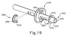
更に、リードスクリュー(254、256)はそれぞれ、図18〜図19に示すように対応のテンショナー(266)を介して並進可能部材(232、233)にそれぞれ接続される。各テンショナー(266)は、対応の並進可能部材(232、233)と係合したキー止め部(key)(268)を有し、並進可能部材(232、233)の長手方向軸線に沿った遠位又は近位への移動を、高位の関節運動制御ノブ(222)及び低位の関節運動制御ノブ(223)を介して方向付ける。しかしながら、各テンショナー(266)はまた、その対応のリードスクリュー(254、256)を環状チャネル(270)内に回転可能に受容し、これにより、各リードスクリュー(254、256)と関節運動ドラム(252)とは、全体として、シャフトアセンブリ(212)を回転させるときに、関節運動に影響を及ぼすことなく、回転制御ノブ(224)(図11参照)を介して回転するように構成される。例として、各テンショナー(266)は、キー止め部(268)を含むC字形部品(272)と環状部品(274)とによって画定される。関節運動ドラム(252)、リードスクリュー(254、256)、及び関節運動制御アセンブリ(218)との他の様々な類似点に関する更なる詳細は、その開示が全体として参照により本明細書に組み込まれる、2015年4月16日出願の「Ultrasonic Surgical Instrument with Opposing Thread Drive for End Effector Articulation」と題された米国特許出願第14/688,663号に記載されている。 Further, the lead screws (254, 256) are respectively connected to the translatable member (232, 233) via the corresponding tensioner (266) as shown in FIGS. 18-19. Each tensioner (266) has a key stop (key) (268) engaged with a corresponding translatable member (232, 233) and is far along the longitudinal axis of the translatable member (232, 233). Positional or proximal movement is directed via the higher joint motion control knob (222) and the lower joint motion control knob (223). However, each tensioner (266) also rotatably accepts its corresponding lead screw (254, 256) into the annular channel (270), thereby each lead screw (254, 256) and range of motion drum (254, 256). 252) is configured as a whole to rotate through the rotation control knob (224) (see FIG. 11) without affecting the joint motion when rotating the shaft assembly (212). As an example, each tensioner (266) is defined by a C-shaped part (272) and an annular part (274) that include a key retainer (268). Further details regarding various other similarities with the joint motion drum (252), lead screw (254, 256), and joint motion control assembly (218) are incorporated herein by reference in their entirety. , US Patent Application No. 14 / 688,663, entitled "Ultrasonic Surgical Instrument with Opposing Threat Drive for End Effector Articulation", filed April 16, 2015.
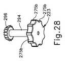
一方、図14〜図19に示すように、操作者が高位の関節運動制御ノブ(222)及び低位の関節運動制御ノブ(223)のいずれかを選択的に回転させて、変速機アセンブリ(226)を介して関節運動セクション(130)(図11参照)を関節運動させることができる。これに対して、変速機アセンブリ(226)は、高位の関節運動制御ノブ(222)及び低位の関節運動制御ノブ(223)が回転していないときに変速機アセンブリ(226)を動作可能にロックすることにより、関節運動制御アセンブリ(218)の意図しない関節運動を阻止するように構成されている。換言すれば、高位の関節運動制御ノブ(222)及び低位の関節運動制御ノブ(223)のいずれか一方の回転が、関節運動制御アセンブリ(218)を効果的にロック解除するが、さもなければ、変速機アセンブリ(226)は、関節運動セクション(130)(図11参照)の関節運動を効果的にロックする。例として、(例えば、エンドエフェクタ(40)が、解剖学的構造又は他の手術器具によって加えられた横断方向の荷重を受けたときになどに)シャフトアセンブリ(212)を介してリードスクリュー(254、256)に加えられる力は、関節運動ドラム(252)を回転させるのに十分な機械的利益を提供することができないので、変速機アセンブリ(226)の自己ロックが生じる。しかしながら、高位の関節運動制御ノブ(222)及び低位の関節運動制御ノブ(223)を介して関節運動ドラム(252)を回転させると、リードスクリュー(254、256)にわたる十分な機械的利益により動きがロック解除され、リードスクリュー(254、256)を並進させ、関節運動セクション(130)(図11参照)を関節運動させる。本実施例では、関節運動制御ノブ(222、223)はそれぞれ、これらノブの周囲に角度の付いた状態で位置付けられた対応のノッチ部(275a、275b)を有する。ノッチ部(275a、275b)は、操作者が高位の関節運動制御ノブ(222)及び低位の関節運動制御ノブ(223)を操作する際の握り易さを改善するように構成されている。 On the other hand, as shown in FIGS. 14 to 19, the operator selectively rotates either the high-level joint motion control knob (222) or the low-level joint motion control knob (223) to assemble the transmission (226). ), The joint movement section (130) (see FIG. 11) can be jointly moved. In contrast, the transmission assembly (226) locks the transmission assembly (226) operably when the high range of motion control knob (222) and the low range of motion control knob (223) are not rotating. By doing so, the joint motion control assembly (218) is configured to prevent unintended joint motion. In other words, the rotation of either the higher joint motion control knob (222) or the lower joint motion control knob (223) effectively unlocks the joint motion control assembly (218), but otherwise. , The transmission assembly (226) effectively locks the joint motion of the joint motion section (130) (see FIG. 11). As an example, a lead screw (254) via a shaft assembly (212) (eg, when the end effector (40) is subjected to a transverse load applied by an anatomical structure or other surgical instrument). Since the force applied to 256) cannot provide sufficient mechanical benefit to rotate the articulated movement drum (252), self-locking of the transmission assembly (226) occurs. However, when the joint movement drum (252) is rotated via the higher joint movement control knob (222) and the lower joint movement control knob (223), it moves with sufficient mechanical benefit over the lead screw (254, 256). Is unlocked, the lead screw (254, 256) is translated and the articulated section (130) (see FIG. 11) is articulated. In this embodiment, each of the joint motion control knobs (222, 223) has a corresponding notch portion (275a, 275b) positioned at an angle around these knobs. The notch portions (275a, 275b) are configured to improve the ease of grip when the operator operates the high-level joint movement control knob (222) and the low-level joint movement control knob (223).
図20〜図21は、簡潔に上述したデュアルモード関節運動のための、高位及び低位の関節運動制御部材(222、223)に接続された高いギヤ比の駆動部(227)及び低いギヤ比の駆動部(228)を示す。図20〜図23に示す実施例では、高いギヤ比の駆動部(227)は、高位の関節運動制御ノブ(222)から下方に延在する複数の歯(278)を有する高位のフェースギヤ(276)を含む。歯(278)はスターバーストパターンに配置される。高位のフェースギヤ(276)は、本実施例において、高位の関節運動制御ノブ(222)と共に一体に形成される。あるいは、高位のフェースギヤ(276)は、シャフトなどの別の構造体によって、高位の関節運動制御ノブ(222)に剛接続されてもよい。このため、高位のフェースギヤ(276)は、高位の関節運動制御ノブ(222)と同時に高位の横軸線の周りで回転可能に駆動されるように構成されている。 20-21 show the high gear ratio drive unit (227) and the low gear ratio connected to the high and low range of motion control members (222, 223) for the dual mode joint movements briefly described above. The drive unit (228) is shown. In the embodiments shown in FIGS. 20-23, the high gear ratio drive unit (227) is a high face gear (278) having a plurality of teeth (278) extending downward from the high joint motion control knob (222). 276) is included. The teeth (278) are arranged in a starburst pattern. The high-level face gear (276) is integrally formed with the high-level joint motion control knob (222) in this embodiment. Alternatively, the higher face gear (276) may be rigidly connected to the higher range of motion control knob (222) by another structure such as a shaft. Therefore, the high-level face gear (276) is configured to be rotatably driven around the high-level horizontal axis at the same time as the high-level joint motion control knob (222).
図20〜図21及び図24〜図27に更に示すように、高位のフェースギヤ(276)は、平歯車(280)及び駆動連結部(282)を介して駆動ドラム(244)に動作可能に接続される。平歯車(280)は、駆動ドラム(244)の一体特徴部であり、駆動ドラム(244)の近位端に位置している。平歯車(280)は、駆動ドラム(244)の長手方向軸線の周りに半径方向外向きに突出する複数の歯(284)を有する。駆動連結部(282)は、近位ギヤ(286)と、遠位ギヤ(288)と、近位ギヤ(286)と遠位ギヤ(288)との間に堅固に延在する連結シャフト(290)と、を有する。近位ギヤ(286)は平歯車の形態であり、遠位ギヤ(288)はかさ歯車の形態である。ギヤ(286、288)は、シャフト(290)と一体的に一緒に回転する。具体的には、ギヤ(286、288)及びシャフト(290)は、シャフトアセンブリ(212)(図11参照)によって画定された長手方向軸線と略平行な軸線の周りを回転するように構成されている。高位のフェースギヤ(276)は遠位ギヤ(288)と噛み合い、近位ギヤ(286)は平歯車(280)と噛み合う。このようにして、連結部(282)は、高位の関節運動制御ノブ(222)の回転をドラム(244)に伝達するように構成されており、これにより、ドラム(244)は、ノブ(222)の回転に応答して回転することになる。 As further shown in FIGS. 20-21 and 24-27, the higher face gear (276) can be moved to the drive drum (244) via the spur gear (280) and the drive coupling (282). Be connected. The spur gear (280) is an integral feature of the drive drum (244) and is located at the proximal end of the drive drum (244). The spur gear (280) has a plurality of teeth (284) protruding radially outward around the longitudinal axis of the drive drum (244). The drive coupling (282) is a coupling shaft (290) that firmly extends between the proximal gear (286), the distal gear (288), and the proximal gear (286) and the distal gear (288). ) And. The proximal gear (286) is in the form of a spur gear and the distal gear (288) is in the form of a bevel gear. The gear (286, 288) rotates integrally with the shaft (290). Specifically, the gears (286, 288) and shaft (290) are configured to rotate around an axis that is substantially parallel to the longitudinal axis defined by the shaft assembly (212) (see FIG. 11). There is. The higher face gear (276) meshes with the distal gear (288) and the proximal gear (286) meshes with the spur gear (280). In this way, the connecting portion (282) is configured to transmit the rotation of the higher range of motion control knob (222) to the drum (244), whereby the drum (244) is configured to the knob (222). ) Will rotate in response to the rotation.
高いギヤ比の駆動部(227)に小型の形態因子を提供するために、遠位ギヤ(289)は、高位の関節運動制御ノブ(222)の中空部(292)内に入れ子にされる。高いギヤ比の駆動部(227)は、本明細書に述べるように駆動ドラム(244)を駆動するために、高位のフェースギヤ(276)と、平歯車(280)と、駆動連結部(282)と、を有するが、駆動ドラム(244)及び/又は関節運動ドラム(252)を直接動かすように構成された代替機構を認識するであろう。例として、高いギヤ比の駆動部(227)は、代替として、シャフトアセンブリ(212)を屈曲させるための他の機構及び/又は電気アセンブリを有してもよい。したがって、本発明は、本実施例の高いギヤ比の駆動部(227)に不必要に限定されることを意図しない。 To provide a small morphology factor for the high gear ratio drive (227), the distal gear (289) is nested within the hollow portion (292) of the higher range of motion control knob (222). The high gear ratio drive unit (227) has a high face gear (276), a spur gear (280), and a drive coupling unit (282) to drive the drive drum (244) as described herein. ), But will recognize an alternative mechanism configured to directly move the drive drum (244) and / or the articulation drum (252). As an example, the high gear ratio drive unit (227) may, as an alternative, have other mechanisms and / or electrical assemblies for bending the shaft assembly (212). Therefore, the present invention is not intended to be unnecessarily limited to the high gear ratio drive unit (227) of the present embodiment.
図20〜図21及び図26〜図29に示すように、本実施例の低いギヤ比の駆動部(228)は、低位の関節運動制御部材(223)から、低位のフェースギヤ(298)と係合する低位の駆動ギヤ(296)まで上方に堅固に延在する、低位の駆動シャフト(294)を含む。低位の駆動ギヤ(296)は、かさ歯車の形態であり、低位の関節運動制御部材(223)、低位の駆動シャフト(294)、及び低位の駆動ギヤ(296)が、低位の横軸線の周りを同時に回転するように構成されるように、低位の駆動シャフト(294)に剛接続されている。低位のフェースギヤ(298)は、駆動ドラム(244)の一体特徴部であり、平歯車(280)より遠位に位置している。低位のフェースギヤ(298)は、駆動ドラム(244)の長手方向軸線を中心にしてスターバーストの配置で近位に突出する複数の歯(300)を備えている。低位のフェースギヤ(298)は、低位の駆動ギヤ(296)と噛み合う。この実施例では、低位のフェースギヤ(298)及び遠位ギヤ(288)は、互いに極めて近接して位置しているが、ギヤ(288、298)は、この実施例では実際には互いに噛み合わないことを理解すべきである。 As shown in FIGS. 20 to 21 and 26 to 29, the low gear ratio drive unit (228) of this embodiment is changed from the low joint motion control member (223) to the low face gear (298). Includes a lower drive shaft (294) that extends firmly upwards to the lower drive gear (296) that engages. The lower drive gear (296) is in the form of a bevel gear, with the lower joint motion control member (223), the lower drive shaft (294), and the lower drive gear (296) around the lower horizontal axis. Is rigidly connected to the lower drive shaft (294) so as to rotate at the same time. The lower face gear (298) is an integral feature of the drive drum (244) and is located distal to the spur gear (280). The lower face gear (298) comprises a plurality of teeth (300) that project proximally in a starburst arrangement about the longitudinal axis of the drive drum (244). The lower face gear (298) meshes with the lower drive gear (296). In this embodiment, the lower face gear (298) and the distal gear (288) are located very close to each other, but the gears (288, 298) do not actually mesh with each other in this embodiment. You should understand that.
低位のフェースギヤ(298)は低位の駆動ギヤ(296)と噛み合うので、低位の関節運動制御部材(223)及び低位の駆動シャフト(294)を介して低位の駆動ギヤ(296)が回転すると、駆動ドラム(244)は、駆動ドラム(244)の長手方向軸線の周りを回転する。駆動ドラム(244)及び低位の駆動シャフト(294)が、互いに90度の角度をなすそれぞれの軸線に沿って配置されているにもかかわらず、低位の駆動ギヤ(296)がかさ歯車構造であることからこの回転がもたらされることを理解すべきである。低いギヤ比の駆動部(228)は、本明細書に述べるように駆動ドラム(244)を駆動するために、低位の駆動シャフト(294)と、低位の駆動ギヤ(296)と、低位のフェースギヤ(298)と、を有するが、駆動ドラム(244)及び/又は関節運動ドラム(252)を直接動かすように構成された代替機構を認識するであろう。例として、低いギヤ比の駆動部(228)は、代替として、シャフトアセンブリ(212)を屈曲させるための他の機構及び/又は電気アセンブリを有してもよい。したがって、本発明は、本実施例の例示的な低いギヤ比の駆動部(228)に不必要に限定されることを意図しない。 Since the lower face gear (298) meshes with the lower drive gear (296), when the lower drive gear (296) rotates via the lower joint motion control member (223) and the lower drive shaft (294), The drive drum (244) rotates around the longitudinal axis of the drive drum (244). Although the drive drum (244) and the lower drive shaft (294) are arranged along their respective axes at 90 degree angles to each other, the lower drive gear (296) has a bevel gear structure. It should be understood that this rotation is brought about by this. The low gear ratio drive unit (228) has a low drive shaft (294), a low drive gear (296), and a low face to drive the drive drum (244) as described herein. It has a gear (298), but will recognize an alternative mechanism configured to move the drive drum (244) and / or the range of motion drum (252) directly. As an example, the low gear ratio drive unit (228) may, as an alternative, have other mechanisms and / or electrical assemblies for bending the shaft assembly (212). Therefore, the present invention is not intended to be unnecessarily limited to the exemplary low gear ratio drive unit (228) of this embodiment.
上述したように、駆動ドラム(244)、平歯車(280)、及び低位のフェースギヤ(298)は、本実施例では共に一体に形成されているので、これらは全体として同時に回転し、これらを介して回転を伝達して関節運動ドラム(252)を駆動するように構成されている。あるいは、駆動ドラム(244)、平歯車(280)、及び低位のフェースギヤ(298)の1つ又は2つ以上は、別体に形成された後、別個の締結具、一体クリップ、接着剤、又は溶接等などの固定具を介して相互に固着されてもよい。更なる例として、駆動ドラム(244)は、遠位フランジ(304)と、駆動ドラム(244)から近位に延在する環状本体(304)と、を含む。遠位フランジ(302)は、複数の角度離間されているキー止めスロット(key slot)(306)を画定し、この複数の角度離間されているキー止めスロット(306)は、関節運動ドラム(252)(図17参照)の近位端によって画定された対応の複数の環状に離間したキー止めタブ(308)(図17参照)に係合して、関節運動ドラム(252)(図17参照)の回転を駆動するように構成されている。更に、駆動ドラム(244)の環状本体(304)と平歯車(280)とは、略等しい外径を有する。これに対し、低位のフェースギヤ(298)は、環状本体(304)が低位のフェースギヤ(298)の内径と略等しい外径を有するように、長手方向軸線を中心にして環状本体(304)を包囲する。 As described above, since the drive drum (244), the spur gear (280), and the lower face gear (298) are integrally formed together in this embodiment, they rotate simultaneously as a whole, and these are rotated at the same time. It is configured to transmit rotation through and drive the joint movement drum (252). Alternatively, one or more of the drive drum (244), spur gear (280), and lower face gear (298) may be formed separately and then separate fasteners, integral clips, adhesives, etc. Alternatively, they may be fixed to each other via a fixing tool such as welding. As a further example, the drive drum (244) includes a distal flange (304) and an annular body (304) extending proximally from the drive drum (244). The distal flange (302) defines a plurality of angle-separated key slots (306), the plurality of angle-separated key slots (306) being a range of motion drum (252). ) (See FIG. 17), engaging with a corresponding plurality of annularly spaced key stop tabs (308) (see FIG. 17) defined by the proximal end of the articulated motion drum (252) (see FIG. 17). It is configured to drive the rotation of. Further, the annular body (304) of the drive drum (244) and the spur gear (280) have substantially the same outer diameter. On the other hand, the lower face gear (298) has an annular body (304) centered on the longitudinal axis so that the annular body (304) has an outer diameter substantially equal to the inner diameter of the lower face gear (298). Siege.
図30〜図31は、真っ直ぐな構成の関節運動制御アセンブリ(218)を示すが、リードスクリュー(254、256)を露出させるために関節運動ドラム(252)は除去されている。図32に示すように、操作者は、関節運動セクション(130)(図11参照)を右方向に関節運動させるために、高位の関節運動制御ノブ(222)を時計回り(上方から見た場合)に操作する。続いて、高位の関節運動制御ノブ(222)は連結シャフト(290)を時計回り(使用中に操作者の視点から見た場合)に駆動する。連結シャフト(290)は平歯車(280)と係合して駆動ドラム(244)を反時計回りに方向付け、これにより関節運動ドラム(252)も同様に反時計回りに方向付けられる。関節運動ドラム(252)が反時計回りに回転すると、近位及び遠位内ネジ山(262、264)は近位及び遠位リードスクリュー(254、256)を、互いから離れる長手方向に、所望の正しい配置に向けて並進させる。このように、高位の関節運動制御ノブ(222)は高いギヤ比の駆動部(227)によって駆動ドラム(244)に接続しており、これにより、高位の関節運動制御ノブ(222)を所定の量だけ時計回りに回転させると、関節運動セクション(130)(図11参照)の比較的大きな程度の関節運動が生じる。したがって、操作者は、エンドエフェクタ(40)(図11参照)を組織に向けて迅速、効果的、かつ選択的に移動させることができるが、高位の関節運動制御ノブ(222)の感度は低い。 30-31 show a straight-structured range of motion control assembly (218), but the range of motion drum (252) has been removed to expose the lead screws (254, 256). As shown in FIG. 32, the operator turns the high range of motion control knob (222) clockwise (when viewed from above) in order to move the joint motion section (130) (see FIG. 11) to the right. ). Subsequently, the high range of motion control knob (222) drives the connecting shaft (290) clockwise (when viewed from the operator's point of view during use). The connecting shaft (290) engages with the spur gear (280) to orient the drive drum (244) counterclockwise, which also orients the range of motion drum (252) counterclockwise. When the articular motion drum (252) rotates counterclockwise, the proximal and distal internal threads (262,264) desire the proximal and distal lead screws (254,256) longitudinally away from each other. Translate towards the correct placement of. As described above, the high-level joint motion control knob (222) is connected to the drive drum (244) by the drive unit (227) having a high gear ratio, whereby the high-level joint motion control knob (222) is designated. Rotation clockwise by an amount results in a relatively large degree of joint movement in the joint movement section (130) (see FIG. 11). Thus, the operator can move the end effector (40) (see FIG. 11) quickly, effectively, and selectively towards the tissue, but the higher range of motion control knob (222) is less sensitive. ..
エンドエフェクタ(40)(図11参照)を組織に対して微調整するために、操作者は低位の関節運動制御ノブ(223)を操作する。一実施例では、操作者は、図33に示す所望の位置に向けて、関節運動セクション(130)(図11参照)をわずかに左方向に方向付ける。このため、操作者は、関節運動セクション(130)(図11参照)を左方向に関節運動させるために、低位の関節運動制御ノブ(223)を反時計回り(上方から見た場合)に操作する。続いて、低位の関節運動制御ノブ(223)は低位の駆動ギヤ(296)を同じように反時計回りに方向付ける。低位の駆動ギヤ(296)は低位のフェースギヤ(298)と係合して駆動ドラム(244)を時計回りに方向付け、これにより関節運動ドラム(252)も同様に時計回りに方向付けられる。関節運動ドラム(252)が時計回りに回転すると、近位及び遠位内ネジ山(262、264)は近位及び遠位リードスクリュー(254、256)を、互いに向かって長手方向に、所望の正しい配置に向けて並進させる。このように、低位の関節運動制御ノブ(223)は低いギヤ比の駆動部(228)によって駆動ドラム(244)に動作可能に接続しており、これにより、低位の関節運動制御ノブ(223)を所定の量だけ反時計回りに回転させると、関節運動セクション(130)(図11参照)の比較的小さな程度の関節運動が生じる。したがって、低位の関節運動制御ノブ(223)の感度はより高いことから、操作者は、エンドエフェクタ(40)(図11参照)を組織に向けてより高精度に、正確に、かつ選択的に移動させることができる。 To fine-tune the end effector (40) (see FIG. 11) to the tissue, the operator operates a lower range of motion control knob (223). In one embodiment, the operator orients the joint motion section (130) (see FIG. 11) slightly to the left towards the desired position shown in FIG. 33. Therefore, the operator operates the lower joint movement control knob (223) counterclockwise (when viewed from above) in order to move the joint movement section (130) (see FIG. 11) to the left. do. Subsequently, the lower joint motion control knob (223) also orients the lower drive gear (296) counterclockwise. The lower drive gear (296) engages with the lower face gear (298) to orient the drive drum (244) clockwise, which also orients the range of motion drum (252) clockwise. When the articular motion drum (252) rotates clockwise, the proximal and distal internal threads (262,264) have the proximal and distal lead screws (254,256) desired longitudinally towards each other. Translate for the correct placement. In this way, the lower joint motion control knob (223) is operably connected to the drive drum (244) by the drive unit (228) with a lower gear ratio, whereby the lower joint motion control knob (223) is connected. When is rotated counterclockwise by a predetermined amount, a relatively small degree of joint movement occurs in the joint movement section (130) (see FIG. 11). Therefore, since the lower range of motion control knob (223) is more sensitive, the operator can more accurately, accurately, and selectively point the end effector (40) (see FIG. 11) toward the tissue. Can be moved.
上記の記述は、高位の関節運動制御ノブ(222)の時計回りの操作及び低位の制御ノブ(223)の反時計回りの操作について説明しているが、高位の関節運動制御ノブ(222)の反時計回りの操作及び低位の関節運動制御ノブ(223)の時計回りの操作はそれぞれ、関節運動制御アセンブリ(218)を上記に述べたのと反対方向に駆動することになる。更に、操作者は、患者を治療するために、高位の関節運動制御ノブ(222)及び低位の関節運動制御ノブ(223)を任意の所望の順序で操作することを望む場合がある。あるいは、操作者は、高位の関節運動制御ノブ(222)及び低位の関節運動制御ノブ(223)の一方のみを使用することを望む場合がある。したがって、手術器具(210)の使用は、本明細書に記載した例示的な使用に不必要に限定されることを意図しないことを理解すべきである。更に、上記に述べた関節運動制御アセンブリ(218)は、高いギヤ比の駆動部(227)及び低いギヤ比の駆動部(228)の2つに由来する2つの異なる感度を有するデュアルモードであるが、望ましいと考えられる追加の感度のために、追加のモード及び駆動部が関節運動制御アセンブリ(218)に組み込まれてもよいことを理解されたい。 The above description describes the clockwise operation of the higher joint motion control knob (222) and the counterclockwise operation of the lower control knob (223), but of the higher joint motion control knob (222). The counterclockwise operation and the clockwise operation of the lower joint motion control knob (223) will each drive the joint motion control assembly (218) in the opposite direction as described above. In addition, the operator may wish to operate the higher range of motion control knobs (222) and the lower range of motion control knobs (223) in any desired order to treat the patient. Alternatively, the operator may wish to use only one of the higher range of motion control knob (222) and the lower range of motion control knob (223). Therefore, it should be understood that the use of surgical instruments (210) is not intended to be unnecessarily limited to the exemplary uses described herein. Further, the joint motion control assembly (218) described above is a dual mode having two different sensitivities derived from two, a high gear ratio drive unit (227) and a low gear ratio drive unit (228). However, it should be understood that additional modes and drives may be incorporated into the articulation control assembly (218) for additional sensitivities deemed desirable.
III.代表的な組み合わせ
以下の実施例は、本明細書の教示を組み合わせるか又は適用することができる、種々の非網羅的な方法に関する。以下の実施例は、本出願における又は本出願の後の出願におけるどの時点でも提示され得る、いずれの請求項の適用範囲をも限定することを目的としたものではない、と理解すべきである。一切の棄権をも意図するものではない。以下の実施例は、単なる例示の目的で与えられるものにすぎない。本明細書の様々な教示は、その他の多くの方法で構成及び適用が可能であると考えられている。また、いくつかの変形形態では、以下の実施例において言及される特定の特徴を省略してよいことも、考えられる。したがって、本発明者又は本発明者の利益の継承者により、後日、そうである旨が明示的に示されない限り、以下に言及される態様又は特徴のいずれも重要なものとして見なされるべきではない。以下に言及される特徴以外の更なる特徴を含む請求項が本出願において、又は本出願に関連する後の出願において示される場合、これらの更なる特徴は、特許性に関連するいずれかの理由により追加されたものとしても、仮定されるべきではない。III. Representative Combinations The following examples relate to various non-exhaustive methods to which the teachings herein can be combined or applied. It should be understood that the following examples are not intended to limit the scope of any claim that may be presented at any time in this application or in subsequent applications. .. It is not intended to abstain at all. The following examples are given for purposes of illustration only. It is believed that the various teachings herein can be constructed and applied in many other ways. It is also conceivable that in some variants, certain features referred to in the following examples may be omitted. Therefore, any of the embodiments or features referred to below should not be considered significant unless explicitly indicated at a later date by the inventor or the successor to the interests of the inventor. .. Where a claim containing additional features other than those referred to below is presented in this application or in a later application related to this application, these additional features are any reason related to patentability. Should not be assumed, even if added by.
(実施例1)
手術器具であって、
(a)長手方向軸線を画定するシャフトアセンブリであって、
(i)近位端部分と、
(ii)エンドエフェクタを有する遠位端部分と、
(iii)エンドエフェクタを長手方向軸線から偏向させるように構成された関節運動セクションと、を含む、シャフトアセンブリと、
(b)シャフトアセンブリの近位端部分に接続された関節運動制御アセンブリであって、
(i)第1の関節運動制御部材と、
(ii)第2の関節運動制御部材と、
(iii)変速機アセンブリであって、
(A)高いギヤ比の駆動部であって、第1の関節運動制御部材の作動に応答して、エンドエフェクタを高速の関節運動で偏向させるように関節運動セクションを駆動するように構成された、高いギヤ比の駆動部と、
(B)低いギヤ比の駆動部であって、第2の関節運動制御部材の作動に応答して、エンドエフェクタを低速の関節運動で偏向させるように関節運動セクションを駆動するように構成された、低いギヤ比の駆動部と、を含む、変速機アセンブリと、を含む、関節運動制御アセンブリと、を含む、手術器具。(Example 1)
It ’s a surgical instrument,
(A) A shaft assembly that defines a longitudinal axis.
(I) Proximal end and
(Ii) A distal end portion with an end effector,
(Iii) A shaft assembly, including a range of motion section configured to deflect the end effector from the longitudinal axis.
(B) A joint motion control assembly connected to the proximal end of the shaft assembly.
(I) The first joint movement control member and
(Ii) The second joint movement control member and
(Iii) A transmission assembly
(A) A drive unit having a high gear ratio, which is configured to drive the joint motion section so as to deflect the end effector with high speed joint motion in response to the operation of the first joint motion control member. , High gear ratio drive unit,
(B) A drive unit with a low gear ratio, configured to drive the joint motion section so as to deflect the end effector with slow joint motion in response to the operation of the second joint motion control member. A surgical instrument, including a transmission assembly, including a low gear ratio drive unit, and a range of motion control assembly.
(実施例2)
第1の関節運動制御部材は、シャフトアセンブリに対して回転可能に取り付けられ、かつ、回転可能に操作されるように構成されており、第2の関節運動制御部材は、シャフトアセンブリに対して回転可能に取り付けられ、かつ、回転可能に操作されるように構成されている、実施例1に記載の手術器具。(Example 2)
The first joint motion control member is configured to be rotatably attached to and rotatably operated with respect to the shaft assembly, and the second joint motion control member is rotatable with respect to the shaft assembly. The surgical instrument according to Example 1, which is possibly attached and configured to be rotatably operated.
(実施例3)
変速機アセンブリは、関節運動セクションに動作可能に接続され、かつ高いギヤ比の駆動部及び低いギヤ比の駆動部のそれぞれと係合する駆動部材を更に有し、駆動部材は、高いギヤ比の駆動部及び低いギヤ比の駆動部のそれぞれによって駆動されて、高いギヤ比の駆動部及び低いギヤ比の駆動部からの運動を、関節運動セクションに向けて伝達し、遠位端部分を長手方向軸線から偏向させるように構成されている、実施例1又は2に記載の手術器具。(Example 3)
The transmission assembly is operably connected to the articulated motion section and further comprises a drive member that engages with each of a high gear ratio drive unit and a low gear ratio drive unit, the drive member having a high gear ratio. Driven by the drive unit and the drive unit with a low gear ratio, respectively, the motion from the drive unit with a high gear ratio and the drive unit with a low gear ratio is transmitted toward the joint motion section, and the distal end portion is longitudinally oriented. The surgical instrument according to Example 1 or 2, which is configured to deflect from the axis.
(実施例4)
駆動部材は、長手方向軸線に沿って延在する駆動ドラムを含み、駆動ドラムは、高いギヤ比の駆動部及び低いギヤ比の駆動部のそれぞれによって長手方向軸線の周りで回転可能に駆動されるように構成されている、実施例3に記載の手術器具。(Example 4)
The drive member includes a drive drum extending along the longitudinal axis, which is rotatably driven around the longitudinal axis by each of a high gear ratio drive and a low gear ratio drive. The surgical instrument according to Example 3, which is configured as follows.
(実施例5)
低いギヤ比の駆動部は第1のフェースギヤを含み、高いギヤ比の駆動部は平歯車を含み、第1のフェースギヤは、駆動ドラムに剛接続され、かつ長手方向軸線の周りに延在し、平歯車は、駆動ドラムに剛接続され、かつ長手方向軸線の周りに延在し、第1のフェースギヤ及び平歯車は、駆動ドラムと共に長手方向軸線の周りを同時に回転するように構成されている、実施例4に記載の手術器具。(Example 5)
The low gear ratio drive contains the first face gear, the high gear ratio drive contains the spur gear, and the first face gear is rigidly connected to the drive drum and extends around the longitudinal axis. The spur gear is rigidly connected to the drive drum and extends around the longitudinal axis, and the first face gear and spur gear are configured to rotate simultaneously with the drive drum around the longitudinal axis. The surgical instrument according to Example 4.
(実施例6)
第1のフェースギヤは、第2の関節運動制御部材によって回転可能に駆動されるように構成されており、平歯車は、第1の関節運動制御部材によって回転可能に駆動されるように構成されている、実施例5に記載の手術器具。(Example 6)
The first face gear is configured to be rotatably driven by a second joint motion control member, and the spur gear is configured to be rotatably driven by a first joint motion control member. The surgical instrument according to Example 5.
(実施例7)
第2の関節運動制御部材は低位の関節運動制御ノブを含み、第1の関節運動制御部材は高位の関節運動制御ノブを含む、実施例6に記載の手術器具。(Example 7)
The surgical instrument according to Example 6, wherein the second joint motion control member includes a lower joint motion control knob, and the first joint motion control member includes a higher joint motion control knob.
(実施例8)
低位及び高位の関節運動制御ノブは、それぞれ、低位の横軸線及び高位の横軸線の周りを回転するように構成されており、低位の横軸線及び高位の横軸線のそれぞれは、長手方向軸線に垂直な向きである、実施例7に記載の手術器具。(Example 8)
The low and high range of motion control knobs are configured to rotate around the low and high horizontal axes, respectively, with the low and high horizontal axes respectively on the longitudinal axis. The surgical instrument according to Example 7, which is oriented vertically.
(実施例9)
低いギヤ比の駆動部は、低位の駆動かさ歯車を更に含み、低位の関節運動制御ノブは、低位の駆動シャフトを介して低位の駆動かさ歯車に剛接続され、低位の駆動かさ歯車及び低位の駆動シャフトのそれぞれは、低位の横軸線の周りを回転するように構成されており、第1のフェースギヤは第1のベベルフェースギヤを含み、第1のベベルフェースギヤは、低位の駆動かさ歯車に係合して、低位の駆動かさ歯車によって回転可能に駆動される、実施例8に記載の手術器具。(Example 9)
The low gear ratio drive further includes the low drive bevel gear, and the low joint motion control knob is rigidly connected to the low drive bevel gear via the low drive shaft to provide the low drive bevel gear and the low gear. Each of the drive shafts is configured to rotate around a lower horizontal axis, the first face gear includes a first bevel face gear, and the first bevel face gear is a lower drive bevel gear. 8. The surgical instrument according to Example 8, which is rotatably driven by a lower drive bevel gear in engagement with.
(実施例10)
高いギヤ比の駆動部は、第2のフェースギヤを更に含み、第2のフェースギヤは、高位の関節運動制御ノブから堅固に延在し、第2のフェースギヤは、高位の横軸線の周りを回転するように構成されている、実施例7〜9のいずれか1つ又は2つ以上に記載の手術器具。(Example 10)
The high gear ratio drive further includes a second face gear, the second face gear firmly extending from the higher range of motion control knob, and the second face gear around the higher horizontal axis. The surgical instrument according to any one or more of Examples 7-9, which is configured to rotate.
(実施例11)
高いギヤ比の駆動部は、駆動連結部を更に含み、駆動連結部は、第2のフェースギヤ及び平歯車のそれぞれと係合し、かつ、第2のフェースギヤによって回転可能に駆動され、それによって平歯車を回転可能に駆動するように構成されている、実施例10に記載の手術器具。(Example 11)
The drive unit with a high gear ratio further includes a drive connection unit, which is engaged with each of the second face gear and the spur gear and is rotatably driven by the second face gear. The surgical instrument according to Example 10, which is configured to rotatably drive a spur gear.
(実施例12)
変速機アセンブリは、
(A)長手方向軸線の周りを回転するように構成された関節運動ドラムであって、長手方向軸線の周りに複数の内ネジ山を有する、関節運動ドラムと、
(B)複数の内ネジ山と係合する少なくとも1つのリードスクリューであって、関節運動ドラムが回転すると長手方向軸線に沿って並進して、関節運動セクショを屈曲させるように構成されている、少なくとも1つのリードスクリューと、を更に含み、
高いギヤ比の駆動部及び低いギヤ比の駆動部は、関節運動ドラムに動作可能に接続され、これにより、高位及び第2の関節運動制御部材の選択的操作は、関節運動ドラムを回転させて、少なくとも1つのリードスクリューを介して関節運動セクションを屈曲させるように構成されている、実施例3〜11のいずれか1つ又は2つ以上に記載の手術器具。(Example 12)
The transmission assembly is
(A) A range of motion drum configured to rotate around a longitudinal axis and having a plurality of internal threads around the longitudinal axis.
(B) At least one lead screw that engages with a plurality of internal threads and is configured to translate along the longitudinal axis when the range of motion drum is rotated to bend the range of motion section. Further including at least one lead screw,
The high gear ratio drive and the low gear ratio drive are operably connected to the joint motion drum, whereby the selective operation of the higher and second joint motion control members causes the joint motion drum to rotate. , The surgical instrument according to any one or more of Examples 3-11, which is configured to flex the articular motion section via at least one lead screw.
(実施例13)
少なくとも1つのリードスクリューは、高位及び第2の関節運動制御部材が選択的に操作されなければ自己ロックし、それによって、関節運動セクションの屈曲を阻止し、かつ、高位及び第2の関節運動制御部材を選択的に操作することによってロック解除し、それによって、関節運動セクションを屈曲させるように構成されている、実施例12に記載の手術器具。(Example 13)
The at least one lead screw self-locks if the higher and second joint motion control members are not selectively operated, thereby preventing flexion of the joint motion section and controlling the higher and second joint motion. 12. The surgical instrument according to Example 12, which is configured to unlock by selectively manipulating the member, thereby flexing the range of motion section.
(実施例14)
シャフトアセンブリの遠位端部分に位置するエンドエフェクタを更に含み、エンドエフェクタは超音波ブレードを含み、シャフトアセンブリは音響導波管を更に含み、音響導波管は超音波ブレードと連結され、音響導波管は、近位端部分、関節運動セクション、及び遠位端部分を通って延在する、実施例1〜13のいずれか1つ又は2つ以上に記載の手術器具。(Example 14)
It further includes an end effector located at the distal end of the shaft assembly, the end effector includes an ultrasonic blade, the shaft assembly further includes an acoustic waveguide, the acoustic waveguide is coupled with the ultrasonic blade, and the acoustic conduction. The surgical instrument according to any one or more of Examples 1 to 13, wherein the corrugated tube extends through the proximal end portion, the articular movement section, and the distal end portion.
(実施例15)
使い捨てアセンブリとハンドルアセンブリ部分とを更に含み、使い捨てアセンブリは、シャフトアセンブリと関節運動制御アセンブリとを含み、使い捨てアセンブリは、ハンドルアセンブリ部分に取り外し可能に接続するように構成されている、実施例1〜14のいずれか1つ又は2つ以上に記載の手術器具。(Example 15)
The disposable assembly further comprises a disposable assembly and a handle assembly portion, the disposable assembly comprises a shaft assembly and a joint motion control assembly, and the disposable assembly is configured to be detachably connected to the handle assembly portion, Examples 1-. The surgical instrument according to any one or two or more of 14.
(実施例16)
手術器具のための関節運動制御アセンブリであって、(a)本体と、(b)本体から遠位に延在するシャフトアセンブリであって、シャフトアセンブリは関節運動セクションを含み、シャフトアセンブリは長手方向軸線を画定する、シャフトアセンブリと、(c)シャフトアセンブリの遠位端に位置するエンドエフェクタであって、関節運動セクションは、エンドエフェクタを長手方向軸線から離れるように選択的に偏向させるように動作可能である、エンドエフェクタと、((d)第1の関節運動制御部材と、(e)第2の関節運動制御部材と、(f)本体に動作可能に接続された変速機アセンブリであって、(i)高いギヤ比の駆動部であって、第1の関節運動制御部材の作動に応答して、高速の関節運動でエンドエフェクタを長手方向軸線から偏向させるように関節運動セクションを駆動するように構成されている、高いギヤ比の駆動部と、(ii)低いギヤ比の駆動部であって、第2の関節運動制御部材の作動に応答して、低速の関節運動でエンドエフェクタを長手方向軸線から偏向させるように関節運動セクションを駆動するように構成されている、低いギヤ比の駆動部と、を含む、変速機アセンブリと、を含む、手術器具のための関節運動制御アセンブリ。(Example 16)
A joint motion control assembly for a surgical instrument, (a) a body and (b) a shaft assembly extending distally from the body, the shaft assembly comprising a joint motion section and the shaft assembly longitudinally. A shaft assembly that defines the axis and (c) an end effector located at the distal end of the shaft assembly, the articulatory section acts to selectively deflect the end effector away from the longitudinal axis. Possible end effectors, ((d) first joint motion control member, (e) second joint motion control member, and (f) transmission assembly operably connected to the body. , (I) A drive unit with a high gear ratio that drives the joint motion section to deflect the end effector from the longitudinal axis with high speed joint motion in response to the operation of the first joint motion control member. A drive unit having a high gear ratio and (ii) a drive unit having a low gear ratio, the end effector is operated at a low speed in response to the operation of the second joint motion control member. A joint motion control assembly for surgical instruments, including a transmission assembly, including a low gear ratio drive unit, which is configured to drive the joint motion section to deflect from the longitudinal axis.
(実施例17)
関節運動セクションは、屈曲し、それによって、エンドエフェクタを長手方向軸線から離れる方向に偏向させるように構成されている、実施例16に記載の関節運動制御アセンブリ。(Example 17)
The joint motion control assembly according to Example 16, wherein the joint motion section is configured to flex and thereby deflect the end effector away from the longitudinal axis.
(実施例18)
第1の関節運動制御部材は第1の回転可能部材を含み、第2の関節運動制御部材は第2の回転可能部材を含み、第1の回転可能部材及び第2の回転可能部材は、互いに独立して回転可能である、実施例16〜17のいずれか1つ又は2つ以上に記載の関節運動制御アセンブリ。(Example 18)
The first joint motion control member includes a first rotatable member, the second joint motion control member includes a second rotatable member, and the first rotatable member and the second rotatable member include each other. The joint motion control assembly according to any one or more of Examples 16 to 17, which is independently rotatable.
(実施例19)
第1の回転可能部材及び第2の回転可能部材は、それぞれ長手方向軸線に垂直なそれぞれの軸線の周りで回転可能である、実施例18に記載の関節運動制御アセンブリ。(Example 19)
The joint motion control assembly according to Example 18, wherein the first rotatable member and the second rotatable member are each rotatable about an axis perpendicular to the longitudinal axis.
(実施例20)
器具の操作方法であって、器具は、(a)長手方向軸線を画定するシャフトアセンブリであって、関節運動セクションを有する、シャフトアセンブリと、(b)シャフトアセンブリに固定されたエンドエフェクタと、(c)第1の関節運動制御部であって、関節運動セクションを作動させ、それによって、第1の関節運動速度でエンドエフェクタを長手方向軸線から離れるよう偏向させるように動作可能である、第1の関節運動制御部と、(d)第2の関節運動制御部であって、関節運動セクションを作動させ、それによって、第2の関節運動速度でエンドエフェクタを長手方向軸線から離れるよう偏向させるように動作可能である、第2の関節運動制御部と、を含み、方法は、(a)関節運動セクションが非関節運動状態にあり、これによりエンドエフェクタが長手方向軸線と整列している間に、シャフトアセンブリの遠位端を患者に挿入することと、(b)第1の関節運動制御部を操作して関節運動セクションの粗調整を行い、それによって、第1の関節運動速度でエンドエフェクタを長手方向軸線から離れる方向に偏向させることと、(c)第2の関節運動制御部を操作して関節運動セクションの微調整を行い、それによって、第2の関節運動速度でエンドエフェクタを長手方向軸線から離れるよう偏向させることと、を含み、第2の関節運動速度は第1の関節運動速度よりも遅い、器具の操作方法。(Example 20)
A method of manipulating the device, the device is (a) a shaft assembly that defines a longitudinal axis and has a joint motion section, and (b) an end effector fixed to the shaft assembly. c) A first joint motion control unit capable of activating the joint motion section, thereby deflecting the end effector away from the longitudinal axis at the first joint motion velocity. And (d) the second joint movement control unit, which activates the joint movement section, thereby deflecting the end effector away from the longitudinal axis at the second joint movement velocity. A second articulatory control unit, which is operable, (a) while the articulated section is in a non-articular motion state, thereby aligning the end effector with the longitudinal axis. , Inserting the distal end of the shaft assembly into the patient and (b) manipulating the first joint motion control unit to make coarse adjustments to the joint motion section, thereby the end effector at the first joint motion velocity. Is deflected away from the longitudinal axis, and (c) the second joint motion control unit is manipulated to fine-tune the joint motion section, thereby longitudinaling the end effector at the second joint motion velocity. A method of operating an instrument, comprising deflecting away from the directional axis, the second joint movement speed being slower than the first joint movement speed.
IV.その他
本明細書に記載される器具のいずれの変形形態も、上述されるものに加えて、又はそれらの代わりに、種々のその他の特徴を含んでもよい、と理解すべきである。実施例のみの目的で、本明細書に記載される器具のいずれもが、本明細書に参考として組み込まれる種々の参考文献のいずれかにおいて開示される種々の特徴のうちの、1つ以上を含むことができる。また、多数の方法にて、本明細書の引用文献のいずれかの教示と本明細書の教示とを容易に組み合わせ得るように、本明細書の教示は、本明細書のその他の引用文献のいずれかに記載される器具のいずれにも容易に適用され得る、とも理解すべきである。更に、当業者は、本明細書の種々の教示が電気外科器具、ステープル留め器具、及び他の種類の外科器具に容易に適用され得ることを認識するであろう。本明細書の教示が組み込まれ得るその他の種類の器具が、当業者に明らかであろう。IV. Others It should be understood that any variation of the instruments described herein may include various other features in addition to or in place of those described above. For purposes of embodiments only, any of the instruments described herein has one or more of the various features disclosed in any of the various references incorporated herein by reference. Can include. Also, the teachings of the present specification are in reference to the other references of the present specification so that the teachings of any of the references herein can be easily combined with the teachings of the present specification in a number of ways. It should also be understood that it can be easily applied to any of the instruments described in either. Moreover, one of ordinary skill in the art will recognize that the various teachings herein can be readily applied to electrosurgical instruments, stapled instruments, and other types of surgical instruments. Other types of instruments to which the teachings herein may be incorporated will be apparent to those of skill in the art.
本明細書に参考として組み込まれると言及されたいかなる特許、公報、又はその他の開示内容も、全体的に又は部分的に、組み込まれた内容が現行の定義、見解、又は本明細書に記載されるその他の開示内容とあくまで矛盾しない範囲でのみ本明細書に組み込まれる、と理解されなければならない。それ自体、また必要な範囲で、本明細書に明瞭に記載される開示内容は、参照により本明細書に組み込まれるあらゆる矛盾する記載に優先するものとする。参照により本明細書に組み込まれるものとするが、既存の定義、記述、又は本明細書に記載される他の開示文献と矛盾する任意の文献、又はそれらの部分は、組み込まれる文献と既存の開示内容との間に矛盾が生じない範囲においてのみ組み込まれるものとする。 Any patents, gazettes, or other disclosures referred to herein for reference, in whole or in part, are described in the current definition, opinion, or specification. It should be understood that it is incorporated herein only to the extent that it does not conflict with any other disclosure. As such, and to the extent necessary, the disclosures expressly set forth herein shall supersede any contradictory statements incorporated herein by reference. Any document that is incorporated herein by reference, but is inconsistent with existing definitions, descriptions, or other disclosed documents described herein, or parts thereof, is incorporated and existing. It shall be incorporated only to the extent that there is no contradiction with the disclosed content.
上記の装置の変形形態は、医療専門家により行われる従来の治療及び処置における用途のみではなく、ロボット支援された治療及び処置における用途をも有してよい。実施例のみの目的で、本明細書の種々の教示は、ロボット外科用システム、例えばIntuitive Surgical,Inc.(Sunnyvale,California)によるDAVINCI(商標)システムなどに容易に組み込まれてよい。同様に、本明細書の種々の教示は、その開示が本明細書に参考として組み込まれる、米国特許第6,783,524号、表題:「Robotic Surgical Tool with Ultrasound Cauterizing and Cutting Instrument」(2004年8月31日公開)の種々の教示と容易に組み合わされ得ることを、当業者は理解するであろう。 The variants of the device may have applications in robot-assisted therapies and procedures as well as in conventional therapies and procedures performed by medical professionals. For purposes of embodiments only, the various teachings herein refer to robotic surgical systems such as Intuitive Surgical, Inc. It may be easily incorporated into a DAVINCI ™ system by (Sunnyvale, California). Similarly, the various teachings herein are incorporated herein by reference in US Pat. No. 6,783,524, entitled "Robotic Surgical Tool with Ultrasound Cauterizing and Cutting Instrument" (2004). Those skilled in the art will appreciate that it can be easily combined with the various teachings (published August 31).
上記の変形形態は、1回の使用後に廃棄されるように設計されてもよく、又はそれらは複数回使用されるように設計されてもよい。一方又はその両方の場合において、種々の変形形態は、少なくとも1回の使用後に再利用のために再調整されてよい。再調整は、装置の分解工程、それに続く特定の部分の洗浄又は交換工程、及びその後の再組立て工程の、任意の組み合わせを含んでよい。特に、装置のいくつかの変形形態は分解することができ、かつ、装置の任意の数の特定の部品若しくは部分を、任意の組み合わせにて選択的に交換又は取り外してもよい。特定の部品の洗浄及び/又は交換に際して、装置の特定の変形例を、再調整用の施設において、又は手術の直前に使用者により再組み立てして、その後の使用に供することができる。装置の再調整において、分解、洗浄/交換、及び再組立てのための種々の技術を利用することができることを、当業者は理解するであろう。かかる技術の使用、及び結果として得られる再調整された装置は、すべて本発明の範囲内にある。 The above variants may be designed to be discarded after a single use, or they may be designed to be used multiple times. In one or both cases, the various variants may be readjusted for reuse after at least one use. The readjustment may include any combination of a disassembly step of the device, followed by a cleaning or replacement step of a particular part, and a subsequent reassembly step. In particular, some variants of the device can be disassembled and any number of specific parts or parts of the device may be selectively replaced or removed in any combination. Upon cleaning and / or replacement of certain parts, certain modifications of the device may be reassembled by the user in a readjustment facility or shortly before surgery for subsequent use. Those skilled in the art will appreciate that various techniques for disassembly, cleaning / replacement, and reassembly can be utilized in the readjustment of the device. The use of such techniques and the resulting readjustment device are all within the scope of the present invention.
実施例のみの目的で、本明細書に記載される変形形態は、手術の前及び/又は後に滅菌されてもよい。1つの滅菌技術では、装置をプラスチック製又はTYVEK製のバックなどの閉鎖及び密封された容器に入れる。次いで、容器及び装置を、γ線、X線、又は高エネルギー電子線などの、容器を透過し得る放射線場に置いてよい。放射線は、装置の表面及び容器内の細菌を死滅させ得る。次に、滅菌された装置を、後の使用のために、滅菌容器中で保管してよい。β線若しくはγ線、エチレンオキシド、又は水蒸気が挙げられるがこれらに限定されない、当該技術分野で既知のその他の任意の技術を用いて、装置を滅菌してもよい。 For purposes of embodiments only, the variants described herein may be sterilized before and / or after surgery. In one sterilization technique, the device is placed in a closed and sealed container such as a plastic or TYVEK bag. The vessel and device may then be placed in a radiation field capable of penetrating the vessel, such as gamma rays, X-rays, or high energy electron beams. Radiation can kill bacteria on the surface of the device and in the container. The sterilized device may then be stored in a sterilized container for later use. The device may be sterilized using any other technique known in the art, including but not limited to beta or gamma rays, ethylene oxide, or water vapor.
以上、本発明の種々の実施形態を図示及び説明したが、本発明の範囲から逸脱することなく、当業者による適切な改変により、本明細書に記載される方法及びシステムの更なる適合化を実現することができる。このような可能な改変のうちのいくつかについて述べたが、その他の改変も当業者には明らかであろう。例えば、上記の実施例、実施形態、形状、材料、寸法、比率、工程などは例示的なものであって、必須のものではない。したがって、本発明の範囲は、以下の特許請求の範囲の観点から考慮されるべきものであり、本明細書及び図面において図示され、説明された構造及び動作の細部に限定されないものとして、理解されたい。 Although various embodiments of the present invention have been illustrated and described above, further adaptation of the methods and systems described herein can be made by appropriate modification by those skilled in the art without departing from the scope of the present invention. It can be realized. Some of these possible modifications have been mentioned, but others will be apparent to those of skill in the art. For example, the above examples, embodiments, shapes, materials, dimensions, ratios, processes, etc. are exemplary and not essential. Accordingly, the scope of the invention should be considered in the light of the following claims and is understood to be not limited to the structural and operational details illustrated and described herein and in the drawings. sea bream.
〔実施の態様〕
(1) 手術器具であって、
(a)長手方向軸線を画定するシャフトアセンブリであって、
(i)近位端部分と、
(ii)エンドエフェクタを有する遠位端部分と、
(iii)前記エンドエフェクタを前記長手方向軸線から偏向させるように構成された関節運動セクションと、を含む、シャフトアセンブリと、
(b)前記シャフトアセンブリの前記近位端部分に接続された関節運動制御アセンブリであって、
(i)第1の関節運動制御部材と、
(ii)第2の関節運動制御部材と、
(iii)変速機アセンブリであって、
(A)高いギヤ比の駆動部(high ratio drive)であって、前記第1の関節運動制御部材の作動に応答して、前記エンドエフェクタを高速の関節運動で偏向させるように前記関節運動セクションを駆動するように構成された、高いギヤ比の駆動部と、
(B)低いギヤ比の駆動部(low ratio drive)であって、前記第2の関節運動制御部材の作動に応答して、前記エンドエフェクタを低速の関節運動で偏向させるように前記関節運動セクションを駆動するように構成された、低いギヤ比の駆動部と、を含む、変速機アセンブリと、を含む、関節運動制御アセンブリと、を含む、手術器具。
(2) 前記第1の関節運動制御部材は、前記シャフトアセンブリに対して回転可能に取り付けられ、かつ、回転可能に操作されるように構成されており、前記第2の関節運動制御部材は、前記シャフトアセンブリに対して回転可能に取り付けられ、かつ、回転可能に操作されるように構成されている、実施態様1に記載の手術器具。
(3) 前記変速機アセンブリは、前記関節運動セクションに動作可能に接続され、かつ前記高いギヤ比の駆動部及び前記低いギヤ比の駆動部のそれぞれと係合する駆動部材を更に有し、前記駆動部材は、前記高いギヤ比の駆動部及び前記低いギヤ比の駆動部のそれぞれによって駆動されて、前記高いギヤ比の駆動部及び前記低いギヤ比の駆動部からの運動を、前記関節運動セクションに向けて伝達し、前記遠位端部分を前記長手方向軸線から偏向させるように構成されている、実施態様1に記載の手術器具。
(4) 前記駆動部材は、前記長手方向軸線に沿って延在する駆動ドラムを含み、前記駆動ドラムは、前記高いギヤ比の駆動部及び前記低いギヤ比の駆動部のそれぞれによって前記長手方向軸線の周りで回転可能に駆動されるように構成されている、実施態様3に記載の手術器具。
(5) 前記低いギヤ比の駆動部は第1のフェースギヤを含み、前記高いギヤ比の駆動部は平歯車を含み、前記第1のフェースギヤは、前記駆動ドラムに剛接続され、かつ前記長手方向軸線の周りに延在し、前記平歯車は、前記駆動ドラムに剛接続され、かつ前記長手方向軸線の周りに延在し、前記第1のフェースギヤ及び前記平歯車は、前記駆動ドラムと共に前記長手方向軸線の周りを同時に回転するように構成されている、実施態様4に記載の手術器具。[Implementation mode]
(1) Surgical instrument
(A) A shaft assembly that defines a longitudinal axis.
(I) Proximal end and
(Ii) A distal end portion with an end effector,
(Iii) A shaft assembly comprising a range of motion section configured to deflect the end effector from the longitudinal axis.
(B) A joint motion control assembly connected to the proximal end portion of the shaft assembly.
(I) The first joint movement control member and
(Ii) The second joint movement control member and
(Iii) A transmission assembly
(A) A high ratio drive, the joint motion section such that the end effector is deflected by high speed joint motion in response to the operation of the first joint motion control member. With a high gear ratio drive unit configured to drive
(B) A low ratio drive, the joint motion section such that the end effector is deflected by a slow joint motion in response to the operation of the second joint motion control member. A surgical instrument, including a transmission assembly, including a low gear ratio drive unit, and a joint motion control assembly, which is configured to drive a joint motion control assembly.
(2) The first joint motion control member is configured to be rotatably attached to the shaft assembly and rotatably operated, and the second joint motion control member is configured to be rotatably operated. The surgical instrument according to embodiment 1, which is rotatably attached to the shaft assembly and configured to be rotatably operated.
(3) The transmission assembly further comprises a drive member operably connected to the articulation section and engaged with each of the high gear ratio drive unit and the low gear ratio drive unit. The drive member is driven by each of the high gear ratio drive unit and the low gear ratio drive unit, and moves from the high gear ratio drive unit and the low gear ratio drive unit to the joint motion section. The surgical instrument according to embodiment 1, which is configured to transmit toward and deflect the distal end portion from the longitudinal axis.
(4) The drive member includes a drive drum extending along the longitudinal axis, and the drive drum is provided with the longitudinal axis by each of the high gear ratio drive unit and the low gear ratio drive unit. The surgical instrument according to embodiment 3, which is configured to be rotatably driven around the device.
(5) The low gear ratio drive unit includes a first face gear, the high gear ratio drive unit includes a spur gear, and the first face gear is rigidly connected to the drive drum and said. The spur gear extends around the longitudinal axis, the spur gear is rigidly connected to the drive drum, and extends around the longitudinal axis, and the first face gear and the spur gear are the drive drum. The surgical instrument according to embodiment 4, which is configured to simultaneously rotate around the longitudinal axis.
(6) 前記第1のフェースギヤは、前記第2の関節運動制御部材によって回転可能に駆動されるように構成されており、前記平歯車は、前記第1の関節運動制御部材によって回転可能に駆動されるように構成されている、実施態様5に記載の手術器具。
(7) 前記第2の関節運動制御部材は低位の関節運動制御ノブを含み、前記第1の関節運動制御部材は高位の関節運動制御ノブを含む、実施態様6に記載の手術器具。
(8) 前記低位及び高位の関節運動制御ノブは、それぞれ、低位の横軸線及び高位の横軸線の周りを回転するように構成されており、前記低位の横軸線及び前記高位の横軸線のそれぞれは、前記長手方向軸線に垂直な向きである、実施態様7に記載の手術器具。
(9) 前記低いギヤ比の駆動部は、低位の駆動かさ歯車を更に含み、前記低位の関節運動制御ノブは、低位の駆動シャフトを介して前記低位の駆動かさ歯車に剛接続され、前記低位の駆動かさ歯車及び前記低位の駆動シャフトのそれぞれは、前記低位の横軸線の周りを回転するように構成されており、前記第1のフェースギヤは第1のベベルフェースギヤを含み、前記第1のベベルフェースギヤは、前記低位の駆動かさ歯車に係合して、前記低位の駆動かさ歯車によって回転可能に駆動される、実施態様8に記載の手術器具。
(10) 前記高いギヤ比の駆動部は、第2のフェースギヤを更に含み、前記第2のフェースギヤは、前記高位の関節運動制御ノブから堅固に延在し、前記第2のフェースギヤは、前記高位の横軸線の周りを回転するように構成されている、実施態様7に記載の手術器具。(6) The first face gear is configured to be rotatably driven by the second joint motion control member, and the spur gear is rotatably driven by the first joint motion control member. The surgical instrument according to embodiment 5, which is configured to be driven.
(7) The surgical instrument according to embodiment 6, wherein the second joint motion control member includes a low-level joint motion control knob, and the first joint motion control member includes a high-level joint motion control knob.
(8) The low-level and high-level joint motion control knobs are configured to rotate around the low-level horizontal axis and the high-level horizontal axis, respectively, and the low-level horizontal axis and the high-level horizontal axis, respectively. Is the surgical instrument according to embodiment 7, which is oriented perpendicular to the longitudinal axis.
(9) The low gear ratio drive unit further includes a low drive bevel gear, and the low joint motion control knob is rigidly connected to the low drive bevel gear via a low drive shaft to be rigidly connected to the low drive bevel gear. Each of the drive bevel gear and the lower drive shaft is configured to rotate around the lower horizontal axis, and the first face gear includes a first bevel face gear and the first bevel face gear. 8. The surgical instrument according to embodiment 8, wherein the bevel face gear is rotatably driven by the lower drive bevel gear by engaging with the lower drive bevel gear.
(10) The drive unit having a high gear ratio further includes a second face gear, the second face gear firmly extends from the higher joint motion control knob, and the second face gear has the second face gear. The surgical instrument according to embodiment 7, which is configured to rotate around the high horizontal axis.
(11) 前記高いギヤ比の駆動部は、駆動連結部を更に含み、前記駆動連結部は、前記第2のフェースギヤ及び前記平歯車のそれぞれと係合し、かつ、前記第2のフェースギヤによって回転可能に駆動され、それによって前記平歯車を回転可能に駆動するように構成されている、実施態様10に記載の手術器具。
(12) 前記変速機アセンブリは、
(A)前記長手方向軸線の周りを回転するように構成された関節運動ドラムであって、前記長手方向軸線の周りに複数の内ネジ山を有する、関節運動ドラムと、
(B)前記複数の内ネジ山と係合する少なくとも1つのリードスクリューであって、前記関節運動ドラムが回転すると前記長手方向軸線に沿って並進して、前記関節運動セクショを屈曲させるように構成されている、少なくとも1つのリードスクリューと、を更に含み、
前記高いギヤ比の駆動部及び前記低いギヤ比の駆動部は、前記関節運動ドラムに動作可能に接続され、これにより、前記高位及び第2の関節運動制御部材の選択的操作は、前記関節運動ドラムを回転させて、前記少なくとも1つのリードスクリューを介して前記関節運動セクションを屈曲させるように構成されている、実施態様3に記載の手術器具。
(13) 前記少なくとも1つのリードスクリューは、前記高位及び第2の関節運動制御部材が選択的に操作されなければ自己ロックし、それによって、前記関節運動セクションの屈曲を阻止し、かつ、前記高位及び第2の関節運動制御部材を選択的に操作することによってロック解除し、それによって、前記関節運動セクションを屈曲させるように構成されている、実施態様12に記載の手術器具。
(14) 前記シャフトアセンブリの前記遠位端部分に位置するエンドエフェクタを更に含み、前記エンドエフェクタは超音波ブレードを含み、前記シャフトアセンブリは音響導波管を更に含み、前記音響導波管は前記超音波ブレードと連結され、前記音響導波管は、前記近位端部分、前記関節運動セクション、及び前記遠位端部分を通って延在する、実施態様1に記載の手術器具。
(15) 使い捨てアセンブリとハンドルアセンブリ部分とを更に含み、前記使い捨てアセンブリは、前記シャフトアセンブリと前記関節運動制御アセンブリとを含み、前記使い捨てアセンブリは、前記ハンドルアセンブリ部分に取り外し可能に接続するように構成されている、実施態様1に記載の手術器具。(11) The drive unit having a high gear ratio further includes a drive connection unit, and the drive connection unit engages with each of the second face gear and the spur gear, and the second face gear. 10. The surgical instrument according to
(12) The transmission assembly is
(A) A joint motion drum configured to rotate around the longitudinal axis and having a plurality of internal threads around the longitudinal axis.
(B) At least one lead screw that engages with the plurality of internal threads, and is configured so that when the joint movement drum rotates, it translates along the longitudinal axis and bends the joint movement section. Including at least one lead screw, which has been added,
The high gear ratio drive unit and the low gear ratio drive unit are operably connected to the joint motion drum, whereby the selective operation of the high position and the second joint motion control member is the joint motion. The surgical instrument according to embodiment 3, wherein the drum is rotated to bend the joint motion section via the at least one lead screw.
(13) The at least one lead screw self-locks if the high and second joint motion control members are not selectively operated, thereby preventing flexion of the joint motion section and the high position. The surgical instrument according to
(14) The shaft assembly further comprises an end effector located at the distal end portion of the shaft assembly, the end effector comprises an ultrasonic blade, the shaft assembly further comprises an acoustic waveguide, the acoustic waveguide further comprises an acoustic waveguide. The surgical instrument according to embodiment 1, wherein the acoustic waveguide is coupled to an ultrasonic blade and extends through the proximal end portion, the articulated motion section, and the distal end portion.
(15) A disposable assembly and a handle assembly portion are further included, the disposable assembly includes the shaft assembly and the joint motion control assembly, and the disposable assembly is configured to be removably connected to the handle assembly portion. The surgical instrument according to the first embodiment.
(16) 手術器具のための関節運動制御アセンブリであって、
(a)本体と、
(b)前記本体から遠位に延在するシャフトアセンブリであって、前記シャフトアセンブリは関節運動セクションを含み、前記シャフトアセンブリは長手方向軸線を画定する、シャフトアセンブリと、
(c)前記シャフトアセンブリの遠位端に位置するエンドエフェクタであって、前記関節運動セクションは、前記エンドエフェクタを前記長手方向軸線から離れるように選択的に偏向させるように動作可能である、エンドエフェクタと、
(d)第1の関節運動制御部材と、
(e)第2の関節運動制御部材と、
(f)前記本体に動作可能に接続された変速機アセンブリであって、
(i)高いギヤ比の駆動部であって、前記第1の関節運動制御部材の作動に応答して、高速の関節運動で前記エンドエフェクタを前記長手方向軸線から偏向させるように前記関節運動セクションを駆動するように構成されている、高いギヤ比の駆動部と、
(ii)低いギヤ比の駆動部であって、前記第2の関節運動制御部材の作動に応答して、低速の関節運動で前記エンドエフェクタを前記長手方向軸線から偏向させるように前記関節運動セクションを駆動するように構成されている、低いギヤ比の駆動部と、を含む、変速機アセンブリと、を含む、手術器具のための関節運動制御アセンブリ。
(17) 前記関節運動セクションは、屈曲し、それによって、前記エンドエフェクタを前記長手方向軸線から離れる方向に偏向させるように構成されている、実施態様16に記載の関節運動制御アセンブリ。
(18) 前記第1の関節運動制御部材は第1の回転可能部材を含み、前記第2の関節運動制御部材は第2の回転可能部材を含み、前記第1の回転可能部材及び前記第2の回転可能部材は、互いに独立して回転可能である、実施態様16に記載の関節運動制御アセンブリ。
(19) 前記第1の回転可能部材及び前記第2の回転可能部材は、それぞれ前記長手方向軸線に垂直なそれぞれの軸線の周りで回転可能である、実施態様18に記載の関節運動制御アセンブリ。
(20) 器具の操作方法であって、前記器具は、
(a)長手方向軸線を画定するシャフトアセンブリであって、関節運動セクションを有する、シャフトアセンブリと、
(b)前記シャフトアセンブリに固定されたエンドエフェクタと、
(c)第1の関節運動制御部であって、前記関節運動セクションを作動させ、それによって、第1の関節運動速度で前記エンドエフェクタを前記長手方向軸線から離れるように偏向させるように動作可能である、第1の関節運動制御部と、
(d)第2の関節運動制御部であって、前記関節運動セクションを作動させ、それによって、第2の関節運動速度で前記エンドエフェクタを前記長手方向軸線から離れるように偏向させるように動作可能である、第2の関節運動制御部と、を含み、
前記方法は、
(a)前記関節運動セクションが非関節運動状態にあり、これにより前記エンドエフェクタが前記長手方向軸線と整列している間に、前記シャフトアセンブリの前記遠位端を患者に挿入することと、
(b)前記第1の関節運動制御部を操作して前記関節運動セクションの粗調整を行い、それによって、第1の関節運動速度で前記エンドエフェクタを前記長手方向軸線から離れるように偏向させることと、
(c)前記第2の関節運動制御部を操作して前記関節運動セクションの微調整を行い、それによって、第2の関節運動速度で前記エンドエフェクタを前記長手方向軸線から離れるように偏向させることと、を含み、前記第2の関節運動速度は前記第1の関節運動速度よりも遅い、器具の操作方法。(16) A joint motion control assembly for surgical instruments.
(A) Main body and
(B) A shaft assembly that extends distally from the body, wherein the shaft assembly includes a range of motion section, and the shaft assembly defines a longitudinal axis.
(C) An end effector located at the distal end of the shaft assembly, wherein the range of motion section is capable of selectively deflecting the end effector away from the longitudinal axis. With the effector
(D) The first joint movement control member and
(E) The second joint motion control member and
(F) A transmission assembly operably connected to the main body.
(I) A drive unit having a high gear ratio, the joint motion section such that the end effector is deflected from the longitudinal axis by high-speed joint motion in response to the operation of the first joint motion control member. With a high gear ratio drive unit, which is configured to drive
(Ii) A drive unit having a low gear ratio, the joint motion section such that the end effector is deflected from the longitudinal axis by a slow joint motion in response to the operation of the second joint motion control member. A joint motion control assembly for surgical instruments, including a transmission assembly, including a low gear ratio drive unit, which is configured to drive.
(17) The joint motion control assembly according to
(18) The first joint motion control member includes a first rotatable member, the second joint motion control member includes a second rotatable member, the first rotatable member and the second rotatable member. 16. The joint motion control assembly according to
(19) The joint motion control assembly according to embodiment 18, wherein the first rotatable member and the second rotatable member are each rotatable about an axis perpendicular to the longitudinal axis.
(20) It is a method of operating an instrument, and the instrument is
(A) A shaft assembly that defines a longitudinal axis and has a range of motion section.
(B) The end effector fixed to the shaft assembly and
(C) A first joint motion control unit capable of activating the joint motion section, thereby deflecting the end effector away from the longitudinal axis at the first joint motion velocity. The first joint movement control unit,
(D) A second joint motion control unit capable of activating the joint motion section, thereby deflecting the end effector away from the longitudinal axis at the second joint motion velocity. Including a second joint motion control unit, which is
The method is
(A) Inserting the distal end of the shaft assembly into the patient while the range of motion section is in a non-range of motion state, thereby aligning the end effector with the longitudinal axis.
(B) The first joint movement control unit is operated to make a rough adjustment of the joint movement section, whereby the end effector is deflected away from the longitudinal axis at the first joint movement speed. When,
(C) Manipulating the second joint motion control unit to make fine adjustments to the joint motion section, thereby deflecting the end effector away from the longitudinal axis at the second joint motion velocity. A method of operating an instrument, wherein the second joint movement speed is slower than the first joint movement speed.
Claims (19)
Translated fromJapanese(a)長手方向軸線を画定するシャフトアセンブリであって、
(i)近位端部分と、
(ii)エンドエフェクタを有する遠位端部分と、
(iii)前記エンドエフェクタを前記長手方向軸線から偏向させるように構成された関節運動セクションと、を含む、シャフトアセンブリと、
(b)前記シャフトアセンブリの前記近位端部分に接続された関節運動制御アセンブリであって、
(i)第1の関節運動制御部材と、
(ii)第2の関節運動制御部材と、
(iii)変速機アセンブリであって、
(A)高いギヤ比の駆動部であって、前記第1の関節運動制御部材の作動に応答して、前記エンドエフェクタを高速の関節運動で偏向させるように前記関節運動セクションを駆動するように構成された、高いギヤ比の駆動部と、
(B)低いギヤ比の駆動部であって、前記第2の関節運動制御部材の作動に応答して、前記エンドエフェクタを低速の関節運動で偏向させるように前記関節運動セクションを駆動するように構成された、低いギヤ比の駆動部と、を含む、変速機アセンブリと、を含む、関節運動制御アセンブリと、を含む、手術器具。It ’s a surgical instrument,
(A) A shaft assembly that defines a longitudinal axis.
(I) Proximal end and
(Ii) A distal end portion with an end effector,
(Iii) A shaft assembly comprising a range of motion section configured to deflect the end effector from the longitudinal axis.
(B) A joint motion control assembly connected to the proximal end portion of the shaft assembly.
(I) The first joint movement control member and
(Ii) The second joint movement control member and
(Iii) A transmission assembly
(A) A drive unit having a high gear ratio so as to drive the joint motion section so as to deflect the end effector with high-speed joint motion in response to the operation of the first joint motion control member. A high gear ratio drive unit and a configured drive unit,
(B) A drive unit having a low gear ratio so as to drive the joint movement section so as to deflect the end effector with low-speed joint movement in response to the operation of the second joint movement control member. A surgical instrument, including a transmission assembly, including a low gear ratio drive unit, and a joint motion control assembly.
(A)前記長手方向軸線の周りを回転するように構成された関節運動ドラムであって、前記長手方向軸線の周りに複数の内ネジ山を有する、関節運動ドラムと、
(B)前記複数の内ネジ山と係合する少なくとも1つのリードスクリューであって、前記関節運動ドラムが回転すると前記長手方向軸線に沿って並進して、前記関節運動セクションを屈曲させるように構成されている、少なくとも1つのリードスクリューと、を更に含み、
前記高いギヤ比の駆動部及び前記低いギヤ比の駆動部は、前記関節運動ドラムに動作可能に接続され、これにより、前記第1及び第2の関節運動制御部材の選択的操作は、前記関節運動ドラムを回転させて、前記少なくとも1つのリードスクリューを介して前記関節運動セクションを屈曲させるように構成されている、請求項3に記載の手術器具。The transmission assembly
(A) A joint motion drum configured to rotate around the longitudinal axis and having a plurality of internal threads around the longitudinal axis.
(B) At least one lead screw that engages with the plurality of internal threads so that when the joint movement drum rotates, it translates along the longitudinal axis and bends thejoint movement section. Including at least one lead screw, which has been added,
The high gear ratio drive unit and the low gear ratio drive unit are operably connected to the joint motion drum, wherebythe selective operation of the first and second joint motion control members is performed by the joint. The surgical instrument according to claim 3, wherein the exercise drum is rotated to bend the joint exercise section via the at least one lead screw.
(a)本体と、
(b)前記本体から遠位に延在するシャフトアセンブリであって、前記シャフトアセンブリは関節運動セクションを含み、前記シャフトアセンブリは長手方向軸線を画定する、シャフトアセンブリと、
(c)前記シャフトアセンブリの遠位端に位置するエンドエフェクタであって、前記関節運動セクションは、前記エンドエフェクタを前記長手方向軸線から離れるように選択的に偏向させるように動作可能である、エンドエフェクタと、
(d)第1の関節運動制御部材と、
(e)第2の関節運動制御部材と、
(f)前記本体に動作可能に接続された変速機アセンブリであって、
(i)高いギヤ比の駆動部であって、前記第1の関節運動制御部材の作動に応答して、高速の関節運動で前記エンドエフェクタを前記長手方向軸線から偏向させるように前記関節運動セクションを駆動するように構成されている、高いギヤ比の駆動部と、
(ii)低いギヤ比の駆動部であって、前記第2の関節運動制御部材の作動に応答して、低速の関節運動で前記エンドエフェクタを前記長手方向軸線から偏向させるように前記関節運動セクションを駆動するように構成されている、低いギヤ比の駆動部と、を含む、変速機アセンブリと、を含む、手術器具のための関節運動制御アセンブリ。A range of motion control assembly for surgical instruments
(A) Main body and
(B) A shaft assembly that extends distally from the body, wherein the shaft assembly includes a range of motion section, and the shaft assembly defines a longitudinal axis.
(C) An end effector located at the distal end of the shaft assembly, wherein the range of motion section is capable of selectively deflecting the end effector away from the longitudinal axis. With the effector
(D) The first joint movement control member and
(E) The second joint motion control member and
(F) A transmission assembly operably connected to the main body.
(I) A drive unit having a high gear ratio, the joint motion section such that the end effector is deflected from the longitudinal axis by high-speed joint motion in response to the operation of the first joint motion control member. With a high gear ratio drive unit, which is configured to drive
(Ii) A drive unit having a low gear ratio, the joint motion section such that the end effector is deflected from the longitudinal axis by a slow joint motion in response to the operation of the second joint motion control member. A joint motion control assembly for surgical instruments, including a transmission assembly, including a low gear ratio drive unit, which is configured to drive.
Applications Claiming Priority (3)
| Application Number | Priority Date | Filing Date | Title |
|---|---|---|---|
| US15/088,357 | 2016-04-01 | ||
| US15/088,357US10492819B2 (en) | 2016-04-01 | 2016-04-01 | Surgical instrument with dual mode articulation drive |
| PCT/US2017/024983WO2017173061A1 (en) | 2016-04-01 | 2017-03-30 | Surgical instrument with dual mode articulation drive |
Publications (2)
| Publication Number | Publication Date |
|---|---|
| JP2019513443A JP2019513443A (en) | 2019-05-30 |
| JP6983803B2true JP6983803B2 (en) | 2021-12-17 |
Family
ID=58503775
Family Applications (1)
| Application Number | Title | Priority Date | Filing Date |
|---|---|---|---|
| JP2018551141AActiveJP6983803B2 (en) | 2016-04-01 | 2017-03-30 | Surgical instrument with dual-mode range of motion drive |
Country Status (6)
| Country | Link |
|---|---|
| US (4) | US10492819B2 (en) |
| EP (1) | EP3435895B1 (en) |
| JP (1) | JP6983803B2 (en) |
| CN (1) | CN109152588B (en) |
| BR (1) | BR112018070016B1 (en) |
| WO (1) | WO2017173061A1 (en) |
Families Citing this family (11)
| Publication number | Priority date | Publication date | Assignee | Title |
|---|---|---|---|---|
| US10492819B2 (en) | 2016-04-01 | 2019-12-03 | Ethicon Llc | Surgical instrument with dual mode articulation drive |
| WO2019191015A1 (en)* | 2018-03-29 | 2019-10-03 | Covidien Lp | Robotic surgical systems and instrument drive assemblies |
| EP4140420B1 (en) | 2019-08-30 | 2025-04-02 | Cilag GmbH International | Ultrasonic surgical instrument with a multi-planar articulating shaft assembly |
| US11471181B2 (en) | 2019-08-30 | 2022-10-18 | Cilag Gmbh International | Ultrasonic surgical instrument with axisymmetric clamping |
| US11457945B2 (en) | 2019-08-30 | 2022-10-04 | Cilag Gmbh International | Ultrasonic blade and clamp arm alignment features |
| US11712261B2 (en) | 2019-08-30 | 2023-08-01 | Cilag Gmbh International | Rotatable linear actuation mechanism |
| US11612409B2 (en) | 2019-08-30 | 2023-03-28 | Cilag Gmbh International | Ultrasonic transducer alignment of an articulating ultrasonic surgical instrument |
| US11690642B2 (en) | 2019-08-30 | 2023-07-04 | Cilag Gmbh International | Ultrasonic surgical instrument with a multi-planar articulating shaft assembly |
| CN110811724B (en)* | 2019-12-14 | 2024-09-03 | 上海博洽医疗器械有限公司 | Joint operating mechanism of endoscopic surgical instrument |
| US11541209B2 (en)* | 2019-12-30 | 2023-01-03 | Biosense Webster (Israel) Ltd. | Preventing twisting of pull wires when deflecting an ear-nose-throat tool |
| US11553937B2 (en)* | 2019-12-30 | 2023-01-17 | Biosense Webster (Israel) Ltd. | Deflection mechanism of an ear-nose-throat tool |
Family Cites Families (42)
| Publication number | Priority date | Publication date | Assignee | Title |
|---|---|---|---|---|
| US5322055B1 (en) | 1993-01-27 | 1997-10-14 | Ultracision Inc | Clamp coagulator/cutting system for ultrasonic surgical instruments |
| US6063098A (en) | 1996-12-23 | 2000-05-16 | Houser; Kevin | Articulable ultrasonic surgical apparatus |
| US5873873A (en) | 1997-10-10 | 1999-02-23 | Ethicon Endo-Surgery, Inc. | Ultrasonic clamp coagulator apparatus having improved clamp mechanism |
| US5980510A (en) | 1997-10-10 | 1999-11-09 | Ethicon Endo-Surgery, Inc. | Ultrasonic clamp coagulator apparatus having improved clamp arm pivot mount |
| US6589200B1 (en) | 1999-02-22 | 2003-07-08 | Ethicon Endo-Surgery, Inc. | Articulating ultrasonic surgical shears |
| US5897523A (en) | 1998-04-13 | 1999-04-27 | Ethicon Endo-Surgery, Inc. | Articulating ultrasonic surgical instrument |
| US6454782B1 (en) | 1998-04-13 | 2002-09-24 | Ethicon Endo-Surgery, Inc. | Actuation mechanism for surgical instruments |
| US5989264A (en) | 1998-06-11 | 1999-11-23 | Ethicon Endo-Surgery, Inc. | Ultrasonic polyp snare |
| DE50014373D1 (en) | 1999-09-09 | 2007-07-12 | Tuebingen Scient Medical Gmbh | SURGICAL INSTRUMENT FOR MINIMALLY INVASIVE INTERVENTIONS |
| US6325811B1 (en) | 1999-10-05 | 2001-12-04 | Ethicon Endo-Surgery, Inc. | Blades with functional balance asymmetries for use with ultrasonic surgical instruments |
| US6752815B2 (en) | 2001-01-31 | 2004-06-22 | Ethicon Endo-Surgery, Inc. | Method and waveguides for changing the direction of longitudinal vibrations |
| US6783524B2 (en) | 2001-04-19 | 2004-08-31 | Intuitive Surgical, Inc. | Robotic surgical tool with ultrasound cauterizing and cutting instrument |
| US20060079879A1 (en) | 2004-10-08 | 2006-04-13 | Faller Craig N | Actuation mechanism for use with an ultrasonic surgical instrument |
| US20070191713A1 (en) | 2005-10-14 | 2007-08-16 | Eichmann Stephen E | Ultrasonic device for cutting and coagulating |
| US7621930B2 (en) | 2006-01-20 | 2009-11-24 | Ethicon Endo-Surgery, Inc. | Ultrasound medical instrument having a medical ultrasonic blade |
| US8366727B2 (en) | 2006-06-01 | 2013-02-05 | Ethicon Endo-Surgery, Inc. | Tissue pad ultrasonic surgical instrument |
| JP5165696B2 (en) | 2007-01-16 | 2013-03-21 | エシコン・エンド−サージェリィ・インコーポレイテッド | Ultrasonic device for cutting and coagulation |
| US8057498B2 (en) | 2007-11-30 | 2011-11-15 | Ethicon Endo-Surgery, Inc. | Ultrasonic surgical instrument blades |
| US8931682B2 (en)* | 2007-06-04 | 2015-01-13 | Ethicon Endo-Surgery, Inc. | Robotically-controlled shaft based rotary drive systems for surgical instruments |
| US8105230B2 (en)* | 2007-07-09 | 2012-01-31 | Olympus Medical Systems Corp. | Medical system |
| EP2217157A2 (en) | 2007-10-05 | 2010-08-18 | Ethicon Endo-Surgery, Inc. | Ergonomic surgical instruments |
| WO2009126955A2 (en) | 2008-04-11 | 2009-10-15 | The Regents Of The University Of Michigan | Minimal access tool |
| WO2010030850A2 (en) | 2008-09-12 | 2010-03-18 | Ethicon Endo-Surgery, Inc. | Ultrasonic device for fingertip control |
| US8517239B2 (en)* | 2009-02-05 | 2013-08-27 | Ethicon Endo-Surgery, Inc. | Surgical stapling instrument comprising a magnetic element driver |
| US8461744B2 (en) | 2009-07-15 | 2013-06-11 | Ethicon Endo-Surgery, Inc. | Rotating transducer mount for ultrasonic surgical instruments |
| US8663220B2 (en) | 2009-07-15 | 2014-03-04 | Ethicon Endo-Surgery, Inc. | Ultrasonic surgical instruments |
| US9050093B2 (en) | 2009-10-09 | 2015-06-09 | Ethicon Endo-Surgery, Inc. | Surgical generator for ultrasonic and electrosurgical devices |
| US9220559B2 (en) | 2010-09-24 | 2015-12-29 | Ethicon Endo-Surgery, Inc. | Articulation joint features for articulating surgical device |
| US20120116265A1 (en) | 2010-11-05 | 2012-05-10 | Houser Kevin L | Surgical instrument with charging devices |
| US9381058B2 (en) | 2010-11-05 | 2016-07-05 | Ethicon Endo-Surgery, Llc | Recharge system for medical devices |
| EP2599431A4 (en)* | 2011-05-12 | 2015-04-08 | Olympus Medical Systems Corp | MEDICAL CONTROL DEVICE |
| US10238416B2 (en) | 2012-04-30 | 2019-03-26 | Ethicon Llc | Ultrasonic device for cutting and coagulating |
| US9408622B2 (en) | 2012-06-29 | 2016-08-09 | Ethicon Endo-Surgery, Llc | Surgical instruments with articulating shafts |
| US9393037B2 (en) | 2012-06-29 | 2016-07-19 | Ethicon Endo-Surgery, Llc | Surgical instruments with articulating shafts |
| US9095367B2 (en) | 2012-10-22 | 2015-08-04 | Ethicon Endo-Surgery, Inc. | Flexible harmonic waveguides/blades for surgical instruments |
| US10172636B2 (en) | 2013-09-17 | 2019-01-08 | Ethicon Llc | Articulation features for ultrasonic surgical instrument |
| US9949785B2 (en) | 2013-11-21 | 2018-04-24 | Ethicon Llc | Ultrasonic surgical instrument with electrosurgical feature |
| US9700341B2 (en)* | 2013-12-26 | 2017-07-11 | Ethicon Llc | Loading features for ultrasonic surgical instrument |
| US10349967B2 (en) | 2014-02-28 | 2019-07-16 | Ethicon Llc | Ultrasonic surgical instrument with removable handle assembly |
| US10542976B2 (en)* | 2014-07-31 | 2020-01-28 | Covidien Lp | Powered surgical instrument with pressure sensitive motor speed control |
| US10342567B2 (en) | 2015-04-16 | 2019-07-09 | Ethicon Llc | Ultrasonic surgical instrument with opposing thread drive for end effector articulation |
| US10492819B2 (en) | 2016-04-01 | 2019-12-03 | Ethicon Llc | Surgical instrument with dual mode articulation drive |
- 2016
- 2016-04-01USUS15/088,357patent/US10492819B2/enactiveActive
- 2017
- 2017-03-30WOPCT/US2017/024983patent/WO2017173061A1/ennot_activeCeased
- 2017-03-30CNCN201780028009.5Apatent/CN109152588B/enactiveActive
- 2017-03-30EPEP17716422.5Apatent/EP3435895B1/enactiveActive
- 2017-03-30BRBR112018070016-9Apatent/BR112018070016B1/enactiveIP Right Grant
- 2017-03-30JPJP2018551141Apatent/JP6983803B2/enactiveActive
- 2019
- 2019-06-03USUS16/429,127patent/US11364047B2/enactiveActive
- 2021
- 2021-05-07USUS17/314,684patent/US11806039B2/enactiveActive
- 2023
- 2023-09-21USUS18/471,349patent/US12414794B2/enactiveActive
Also Published As
| Publication number | Publication date |
|---|---|
| US12414794B2 (en) | 2025-09-16 |
| US20190321069A1 (en) | 2019-10-24 |
| BR112018070016B1 (en) | 2023-05-09 |
| JP2019513443A (en) | 2019-05-30 |
| EP3435895A1 (en) | 2019-02-06 |
| US11364047B2 (en) | 2022-06-21 |
| US20240008890A1 (en) | 2024-01-11 |
| CN109152588B (en) | 2021-06-11 |
| US20170281217A1 (en) | 2017-10-05 |
| US20210346049A1 (en) | 2021-11-11 |
| BR112018070016A2 (en) | 2019-02-05 |
| EP3435895B1 (en) | 2021-05-05 |
| CN109152588A (en) | 2019-01-04 |
| US11806039B2 (en) | 2023-11-07 |
| WO2017173061A1 (en) | 2017-10-05 |
| US10492819B2 (en) | 2019-12-03 |
Similar Documents
| Publication | Publication Date | Title |
|---|---|---|
| JP6983803B2 (en) | Surgical instrument with dual-mode range of motion drive | |
| US12318079B2 (en) | Surgical instrument with locking articulation drive wheel | |
| JP6938613B2 (en) | Ultrasonic surgical instrument with electric joint motion drive in the shaft rotation knob | |
| JP7046906B2 (en) | Surgical instrument with selectively locked range of motion assembly | |
| JP6873913B2 (en) | Ultrasound surgical instrument with end effectors that move joints with curved blades | |
| JP6896645B2 (en) | Ultrasonic surgical instrument with opposed thread drive for end effector range of motion | |
| US11457945B2 (en) | Ultrasonic blade and clamp arm alignment features | |
| US12048452B2 (en) | Ultrasonic surgical instrument with axisymmetric clamping | |
| JP6732792B2 (en) | Ultrasonic surgical instrument having a stiffening articulation drive member | |
| KR102149652B1 (en) | Robotic ultrasonic surgical device with articulating end effector | |
| KR102305647B1 (en) | Articulation features for ultrasonic surgical instrument | |
| JP7046826B2 (en) | Range of motion fittings for surgical instruments | |
| WO2015164193A1 (en) | Ultrasonic surgical instrument with end effector having restricted articulation |
Legal Events
| Date | Code | Title | Description |
|---|---|---|---|
| A621 | Written request for application examination | Free format text:JAPANESE INTERMEDIATE CODE: A621 Effective date:20200330 | |
| A131 | Notification of reasons for refusal | Free format text:JAPANESE INTERMEDIATE CODE: A131 Effective date:20210323 | |
| A977 | Report on retrieval | Free format text:JAPANESE INTERMEDIATE CODE: A971007 Effective date:20210326 | |
| A521 | Request for written amendment filed | Free format text:JAPANESE INTERMEDIATE CODE: A523 Effective date:20210609 | |
| TRDD | Decision of grant or rejection written | ||
| A01 | Written decision to grant a patent or to grant a registration (utility model) | Free format text:JAPANESE INTERMEDIATE CODE: A01 Effective date:20211026 | |
| A61 | First payment of annual fees (during grant procedure) | Free format text:JAPANESE INTERMEDIATE CODE: A61 Effective date:20211124 | |
| R150 | Certificate of patent or registration of utility model | Ref document number:6983803 Country of ref document:JP Free format text:JAPANESE INTERMEDIATE CODE: R150 | |
| R250 | Receipt of annual fees | Free format text:JAPANESE INTERMEDIATE CODE: R250 |