JP6983146B2 - catheter - Google Patents
catheterDownload PDFInfo
- Publication number
- JP6983146B2 JP6983146B2JP2018236146AJP2018236146AJP6983146B2JP 6983146 B2JP6983146 B2JP 6983146B2JP 2018236146 AJP2018236146 AJP 2018236146AJP 2018236146 AJP2018236146 AJP 2018236146AJP 6983146 B2JP6983146 B2JP 6983146B2
- Authority
- JP
- Japan
- Prior art keywords
- catheter
- electrode
- electrodes
- lumen
- proximal
- Prior art date
- Legal status (The legal status is an assumption and is not a legal conclusion. Google has not performed a legal analysis and makes no representation as to the accuracy of the status listed.)
- Active
Links
- 230000007246mechanismEffects0.000claimsdescription49
- 230000000712assemblyEffects0.000claimsdescription46
- 238000000429assemblyMethods0.000claimsdescription46
- 210000003105phrenic nerveAnatomy0.000claimsdescription40
- 239000012530fluidSubstances0.000claimsdescription5
- 210000005036nerveAnatomy0.000description52
- 238000002565electrocardiographyMethods0.000description19
- 238000000034methodMethods0.000description18
- 210000004204blood vesselAnatomy0.000description17
- 238000000465mouldingMethods0.000description14
- 230000005684electric fieldEffects0.000description13
- 230000007383nerve stimulationEffects0.000description13
- 239000000853adhesiveSubstances0.000description10
- 230000001070adhesive effectEffects0.000description10
- 230000006870functionEffects0.000description10
- 230000029058respiratory gaseous exchangeEffects0.000description10
- 230000004936stimulating effectEffects0.000description10
- 230000000638stimulationEffects0.000description10
- 238000004519manufacturing processMethods0.000description9
- 238000005399mechanical ventilationMethods0.000description9
- 210000002620vena cava superiorAnatomy0.000description9
- 239000000463materialSubstances0.000description8
- 238000007920subcutaneous administrationMethods0.000description8
- 230000008859changeEffects0.000description7
- 210000002216heartAnatomy0.000description7
- 230000004048modificationEffects0.000description7
- 238000012986modificationMethods0.000description7
- 210000003205muscleAnatomy0.000description7
- 230000002829reductive effectEffects0.000description7
- 229910001220stainless steelInorganic materials0.000description7
- 239000010935stainless steelSubstances0.000description7
- 239000012811non-conductive materialSubstances0.000description6
- BASFCYQUMIYNBI-UHFFFAOYSA-NplatinumChemical compound[Pt]BASFCYQUMIYNBI-UHFFFAOYSA-N0.000description6
- 229920000642polymerPolymers0.000description6
- 238000001746injection mouldingMethods0.000description5
- 230000003014reinforcing effectEffects0.000description5
- 210000001321subclavian veinAnatomy0.000description5
- 238000009423ventilationMethods0.000description5
- 206010003694AtrophyDiseases0.000description4
- 239000004952PolyamideSubstances0.000description4
- 230000004913activationEffects0.000description4
- 230000037444atrophyEffects0.000description4
- 238000005452bendingMethods0.000description4
- 239000008280bloodSubstances0.000description4
- 210000004369bloodAnatomy0.000description4
- 238000013461designMethods0.000description4
- 238000001125extrusionMethods0.000description4
- 239000000976inkSubstances0.000description4
- 229920002647polyamidePolymers0.000description4
- 229920001343polytetrafluoroethylenePolymers0.000description4
- 239000004810polytetrafluoroethyleneSubstances0.000description4
- 238000011282treatmentMethods0.000description4
- 210000003462veinAnatomy0.000description4
- 238000003466weldingMethods0.000description4
- -1MP35NChemical compound0.000description3
- 229920002614Polyether block amidePolymers0.000description3
- NRTOMJZYCJJWKI-UHFFFAOYSA-NTitanium nitrideChemical compound[Ti]#NNRTOMJZYCJJWKI-UHFFFAOYSA-N0.000description3
- 230000008901benefitEffects0.000description3
- 230000006835compressionEffects0.000description3
- 238000007906compressionMethods0.000description3
- 239000004020conductorSubstances0.000description3
- 238000002788crimpingMethods0.000description3
- 230000001419dependent effectEffects0.000description3
- 238000010586diagramMethods0.000description3
- 238000003780insertionMethods0.000description3
- 230000037431insertionEffects0.000description3
- 210000004731jugular veinAnatomy0.000description3
- 238000012544monitoring processMethods0.000description3
- 229910052697platinumInorganic materials0.000description3
- 229920002635polyurethanePolymers0.000description3
- 239000004814polyurethaneSubstances0.000description3
- 208000024891symptomDiseases0.000description3
- 238000012360testing methodMethods0.000description3
- 208000028399Critical IllnessDiseases0.000description2
- 239000004677NylonSubstances0.000description2
- KDLHZDBZIXYQEI-UHFFFAOYSA-NPalladiumChemical compound[Pd]KDLHZDBZIXYQEI-UHFFFAOYSA-N0.000description2
- 208000035873Ventilator-induced diaphragmatic dysfunctionDiseases0.000description2
- 230000001154acute effectEffects0.000description2
- 238000007792additionMethods0.000description2
- 206010002026amyotrophic lateral sclerosisDiseases0.000description2
- 210000003484anatomyAnatomy0.000description2
- 210000003050axonAnatomy0.000description2
- 239000000560biocompatible materialSubstances0.000description2
- 230000005540biological transmissionEffects0.000description2
- 239000011248coating agentSubstances0.000description2
- 238000000576coating methodMethods0.000description2
- 230000000694effectsEffects0.000description2
- 238000010438heat treatmentMethods0.000description2
- 238000009413insulationMethods0.000description2
- 238000000608laser ablationMethods0.000description2
- 230000000670limiting effectEffects0.000description2
- 210000004072lungAnatomy0.000description2
- 239000000155meltSubstances0.000description2
- 201000000585muscular atrophyDiseases0.000description2
- 229910001000nickel titaniumInorganic materials0.000description2
- HLXZNVUGXRDIFK-UHFFFAOYSA-Nnickel titaniumChemical compound[Ti].[Ti].[Ti].[Ti].[Ti].[Ti].[Ti].[Ti].[Ti].[Ti].[Ti].[Ni].[Ni].[Ni].[Ni].[Ni].[Ni].[Ni].[Ni].[Ni].[Ni].[Ni].[Ni].[Ni].[Ni]HLXZNVUGXRDIFK-UHFFFAOYSA-N0.000description2
- 229920001778nylonPolymers0.000description2
- 230000036961partial effectEffects0.000description2
- 230000001830phrenic effectEffects0.000description2
- 239000004033plasticSubstances0.000description2
- 229920003023plasticPolymers0.000description2
- 239000004417polycarbonateSubstances0.000description2
- 229920000515polycarbonatePolymers0.000description2
- 229940125723sedative agentDrugs0.000description2
- 239000000932sedative agentSubstances0.000description2
- 238000006467substitution reactionMethods0.000description2
- 230000007704transitionEffects0.000description2
- 208000019901Anxiety diseaseDiseases0.000description1
- OKTJSMMVPCPJKN-UHFFFAOYSA-NCarbonChemical compound[C]OKTJSMMVPCPJKN-UHFFFAOYSA-N0.000description1
- 239000004215Carbon black (E152)Substances0.000description1
- 208000003417Central Sleep ApneaDiseases0.000description1
- 208000000094Chronic PainDiseases0.000description1
- 206010066131Congenital central hypoventilation syndromeDiseases0.000description1
- RYECOJGRJDOGPP-UHFFFAOYSA-NEthylureaChemical compoundCCNC(N)=ORYECOJGRJDOGPP-UHFFFAOYSA-N0.000description1
- 208000004852Lung InjuryDiseases0.000description1
- 241000124008MammaliaSpecies0.000description1
- 206010028289Muscle atrophyDiseases0.000description1
- 208000002193PainDiseases0.000description1
- 241000282577Pan troglodytesSpecies0.000description1
- 206010035664PneumoniaDiseases0.000description1
- 239000004698PolyethyleneSubstances0.000description1
- 239000004721Polyphenylene oxideSubstances0.000description1
- CZMRCDWAGMRECN-UGDNZRGBSA-NSucroseChemical compoundO[C@H]1[C@H](O)[C@@H](CO)O[C@@]1(CO)O[C@@H]1[C@H](O)[C@@H](O)[C@H](O)[C@@H](CO)O1CZMRCDWAGMRECN-UGDNZRGBSA-N0.000description1
- 229930006000SucroseNatural products0.000description1
- 229920006362Teflon®Polymers0.000description1
- 239000004433Thermoplastic polyurethaneSubstances0.000description1
- 206010069363Traumatic lung injuryDiseases0.000description1
- 229910052770UraniumInorganic materials0.000description1
- 208000027418Wounds and injuryDiseases0.000description1
- 230000005856abnormalityEffects0.000description1
- 238000009825accumulationMethods0.000description1
- 230000009471actionEffects0.000description1
- 230000036982action potentialEffects0.000description1
- 230000003213activating effectEffects0.000description1
- 230000002411adverseEffects0.000description1
- 230000008382alveolar damageEffects0.000description1
- 229940035674anestheticsDrugs0.000description1
- 230000036506anxietyEffects0.000description1
- QVGXLLKOCUKJST-UHFFFAOYSA-Natomic oxygenChemical compound[O]QVGXLLKOCUKJST-UHFFFAOYSA-N0.000description1
- 208000020538atrophic muscular diseaseDiseases0.000description1
- 230000004888barrier functionEffects0.000description1
- 230000009286beneficial effectEffects0.000description1
- 230000002457bidirectional effectEffects0.000description1
- 230000015572biosynthetic processEffects0.000description1
- 238000010241blood samplingMethods0.000description1
- 210000004556brainAnatomy0.000description1
- 229910052799carbonInorganic materials0.000description1
- 210000004889cervical nerveAnatomy0.000description1
- 210000000038chestAnatomy0.000description1
- 230000001684chronic effectEffects0.000description1
- 239000012141concentrateSubstances0.000description1
- 208000036970congenital 1 with or without Hirschsprung disease central hypoventilation syndromeDiseases0.000description1
- 230000007797corrosionEffects0.000description1
- 238000005260corrosionMethods0.000description1
- 230000008878couplingEffects0.000description1
- 238000010168coupling processMethods0.000description1
- 238000005859coupling reactionMethods0.000description1
- 238000005520cutting processMethods0.000description1
- 230000006378damageEffects0.000description1
- 230000003247decreasing effectEffects0.000description1
- 235000013681dietary sucroseNutrition0.000description1
- 230000003292diminished effectEffects0.000description1
- 201000010099diseaseDiseases0.000description1
- 208000037265diseases, disorders, signs and symptomsDiseases0.000description1
- 239000003814drugSubstances0.000description1
- 229940079593drugDrugs0.000description1
- 239000007772electrode materialSubstances0.000description1
- 230000005674electromagnetic inductionEffects0.000description1
- 238000005516engineering processMethods0.000description1
- 229920002313fluoropolymerPolymers0.000description1
- 239000004811fluoropolymerSubstances0.000description1
- 239000011888foilSubstances0.000description1
- 239000003193general anesthetic agentSubstances0.000description1
- PCHJSUWPFVWCPO-UHFFFAOYSA-NgoldChemical compound[Au]PCHJSUWPFVWCPO-UHFFFAOYSA-N0.000description1
- 229910052737goldInorganic materials0.000description1
- 239000010931goldSubstances0.000description1
- 230000036541healthEffects0.000description1
- 229930195733hydrocarbonNatural products0.000description1
- 150000002430hydrocarbonsChemical class0.000description1
- 208000015181infectious diseaseDiseases0.000description1
- 239000011810insulating materialSubstances0.000description1
- 229910052741iridiumInorganic materials0.000description1
- GKOZUEZYRPOHIO-UHFFFAOYSA-Niridium atomChemical compound[Ir]GKOZUEZYRPOHIO-UHFFFAOYSA-N0.000description1
- 230000007794irritationEffects0.000description1
- WABPQHHGFIMREM-UHFFFAOYSA-Nlead(0)Chemical compound[Pb]WABPQHHGFIMREM-UHFFFAOYSA-N0.000description1
- 230000007774longtermEffects0.000description1
- 231100000515lung injuryToxicity0.000description1
- 238000002844meltingMethods0.000description1
- 230000008018meltingEffects0.000description1
- 230000028161membrane depolarizationEffects0.000description1
- 229910052751metalInorganic materials0.000description1
- 239000002184metalSubstances0.000description1
- 238000002156mixingMethods0.000description1
- 230000020763muscle atrophyEffects0.000description1
- 210000001087myotubuleAnatomy0.000description1
- 230000007433nerve pathwayEffects0.000description1
- 230000001537neural effectEffects0.000description1
- 230000010004neural pathwayEffects0.000description1
- 210000000118neural pathwayAnatomy0.000description1
- 210000000056organAnatomy0.000description1
- OTCVAHKKMMUFAY-UHFFFAOYSA-NoxosilverChemical class[Ag]=OOTCVAHKKMMUFAY-UHFFFAOYSA-N0.000description1
- 229910052760oxygenInorganic materials0.000description1
- 239000001301oxygenSubstances0.000description1
- RVTZCBVAJQQJTK-UHFFFAOYSA-Noxygen(2-);zirconium(4+)Chemical compound[O-2].[O-2].[Zr+4]RVTZCBVAJQQJTK-UHFFFAOYSA-N0.000description1
- 229910052763palladiumInorganic materials0.000description1
- 230000037361pathwayEffects0.000description1
- 230000035515penetrationEffects0.000description1
- VPRUMANMDWQMNF-UHFFFAOYSA-Nphenylethane boronic acidChemical compoundOB(O)CCC1=CC=CC=C1VPRUMANMDWQMNF-UHFFFAOYSA-N0.000description1
- 230000000704physical effectEffects0.000description1
- HWLDNSXPUQTBOD-UHFFFAOYSA-Nplatinum-iridium alloyChemical compound[Ir].[Pt]HWLDNSXPUQTBOD-UHFFFAOYSA-N0.000description1
- 229920000728polyesterPolymers0.000description1
- 229920000570polyetherPolymers0.000description1
- 229920000573polyethylenePolymers0.000description1
- 229920006264polyurethane filmPolymers0.000description1
- 239000011253protective coatingSubstances0.000description1
- 230000010349pulsationEffects0.000description1
- 238000004080punchingMethods0.000description1
- 238000011084recoveryMethods0.000description1
- 230000000241respiratory effectEffects0.000description1
- 210000003019respiratory muscleAnatomy0.000description1
- 230000004044responseEffects0.000description1
- 230000035807sensationEffects0.000description1
- 238000009958sewingMethods0.000description1
- 239000012781shape memory materialSubstances0.000description1
- 229910001285shape-memory alloyInorganic materials0.000description1
- 230000008054signal transmissionEffects0.000description1
- 229920002379silicone rubberPolymers0.000description1
- 239000004945silicone rubberSubstances0.000description1
- 229910052709silverInorganic materials0.000description1
- 239000004332silverSubstances0.000description1
- 229910001923silver oxideInorganic materials0.000description1
- 238000005476solderingMethods0.000description1
- 210000000278spinal cordAnatomy0.000description1
- 238000010254subcutaneous injectionMethods0.000description1
- 239000007929subcutaneous injectionSubstances0.000description1
- 229960004793sucroseDrugs0.000description1
- 230000001225therapeutic effectEffects0.000description1
- 239000012815thermoplastic materialSubstances0.000description1
- 229920002803thermoplastic polyurethanePolymers0.000description1
- 210000003448thoracic nerveAnatomy0.000description1
- 210000001519tissueAnatomy0.000description1
- 231100000331toxicToxicity0.000description1
- 230000002588toxic effectEffects0.000description1
- 238000002627tracheal intubationMethods0.000description1
- 238000012384transportation and deliveryMethods0.000description1
- 210000005166vasculatureAnatomy0.000description1
- 230000002747voluntary effectEffects0.000description1
Images


Classifications
- A—HUMAN NECESSITIES
- A61—MEDICAL OR VETERINARY SCIENCE; HYGIENE
- A61N—ELECTROTHERAPY; MAGNETOTHERAPY; RADIATION THERAPY; ULTRASOUND THERAPY
- A61N1/00—Electrotherapy; Circuits therefor
- A61N1/18—Applying electric currents by contact electrodes
- A61N1/32—Applying electric currents by contact electrodes alternating or intermittent currents
- A61N1/36—Applying electric currents by contact electrodes alternating or intermittent currents for stimulation
- A61N1/3601—Applying electric currents by contact electrodes alternating or intermittent currents for stimulation of respiratory organs
- A—HUMAN NECESSITIES
- A61—MEDICAL OR VETERINARY SCIENCE; HYGIENE
- A61B—DIAGNOSIS; SURGERY; IDENTIFICATION
- A61B5/00—Measuring for diagnostic purposes; Identification of persons
- A61B5/02—Detecting, measuring or recording for evaluating the cardiovascular system, e.g. pulse, heart rate, blood pressure or blood flow
- A61B5/024—Measuring pulse rate or heart rate
- A61B5/0245—Measuring pulse rate or heart rate by using sensing means generating electric signals, i.e. ECG signals
- A—HUMAN NECESSITIES
- A61—MEDICAL OR VETERINARY SCIENCE; HYGIENE
- A61B—DIAGNOSIS; SURGERY; IDENTIFICATION
- A61B5/00—Measuring for diagnostic purposes; Identification of persons
- A61B5/24—Detecting, measuring or recording bioelectric or biomagnetic signals of the body or parts thereof
- A61B5/25—Bioelectric electrodes therefor
- A61B5/279—Bioelectric electrodes therefor specially adapted for particular uses
- A61B5/28—Bioelectric electrodes therefor specially adapted for particular uses for electrocardiography [ECG]
- A61B5/283—Invasive
- A61B5/287—Holders for multiple electrodes, e.g. electrode catheters for electrophysiological study [EPS]
- A—HUMAN NECESSITIES
- A61—MEDICAL OR VETERINARY SCIENCE; HYGIENE
- A61B—DIAGNOSIS; SURGERY; IDENTIFICATION
- A61B5/00—Measuring for diagnostic purposes; Identification of persons
- A61B5/68—Arrangements of detecting, measuring or recording means, e.g. sensors, in relation to patient
- A61B5/6846—Arrangements of detecting, measuring or recording means, e.g. sensors, in relation to patient specially adapted to be brought in contact with an internal body part, i.e. invasive
- A61B5/6847—Arrangements of detecting, measuring or recording means, e.g. sensors, in relation to patient specially adapted to be brought in contact with an internal body part, i.e. invasive mounted on an invasive device
- A61B5/6852—Catheters
- A—HUMAN NECESSITIES
- A61—MEDICAL OR VETERINARY SCIENCE; HYGIENE
- A61M—DEVICES FOR INTRODUCING MEDIA INTO, OR ONTO, THE BODY; DEVICES FOR TRANSDUCING BODY MEDIA OR FOR TAKING MEDIA FROM THE BODY; DEVICES FOR PRODUCING OR ENDING SLEEP OR STUPOR
- A61M25/00—Catheters; Hollow probes
- A—HUMAN NECESSITIES
- A61—MEDICAL OR VETERINARY SCIENCE; HYGIENE
- A61M—DEVICES FOR INTRODUCING MEDIA INTO, OR ONTO, THE BODY; DEVICES FOR TRANSDUCING BODY MEDIA OR FOR TAKING MEDIA FROM THE BODY; DEVICES FOR PRODUCING OR ENDING SLEEP OR STUPOR
- A61M25/00—Catheters; Hollow probes
- A61M25/0021—Catheters; Hollow probes characterised by the form of the tubing
- A61M25/0023—Catheters; Hollow probes characterised by the form of the tubing by the form of the lumen, e.g. cross-section, variable diameter
- A61M25/0026—Multi-lumen catheters with stationary elements
- A61M25/0029—Multi-lumen catheters with stationary elements characterized by features relating to least one lumen located at the middle part of the catheter, e.g. slots, flaps, valves, cuffs, apertures, notches, grooves or rapid exchange ports
- A—HUMAN NECESSITIES
- A61—MEDICAL OR VETERINARY SCIENCE; HYGIENE
- A61M—DEVICES FOR INTRODUCING MEDIA INTO, OR ONTO, THE BODY; DEVICES FOR TRANSDUCING BODY MEDIA OR FOR TAKING MEDIA FROM THE BODY; DEVICES FOR PRODUCING OR ENDING SLEEP OR STUPOR
- A61M25/00—Catheters; Hollow probes
- A61M25/01—Introducing, guiding, advancing, emplacing or holding catheters
- A61M25/0105—Steering means as part of the catheter or advancing means; Markers for positioning
- A61M25/0133—Tip steering devices
- A61M25/0147—Tip steering devices with movable mechanical means, e.g. pull wires
- A—HUMAN NECESSITIES
- A61—MEDICAL OR VETERINARY SCIENCE; HYGIENE
- A61N—ELECTROTHERAPY; MAGNETOTHERAPY; RADIATION THERAPY; ULTRASOUND THERAPY
- A61N1/00—Electrotherapy; Circuits therefor
- A61N1/02—Details
- A61N1/04—Electrodes
- A61N1/05—Electrodes for implantation or insertion into the body, e.g. heart electrode
- A61N1/0551—Spinal or peripheral nerve electrodes
- A—HUMAN NECESSITIES
- A61—MEDICAL OR VETERINARY SCIENCE; HYGIENE
- A61N—ELECTROTHERAPY; MAGNETOTHERAPY; RADIATION THERAPY; ULTRASOUND THERAPY
- A61N1/00—Electrotherapy; Circuits therefor
- A61N1/18—Applying electric currents by contact electrodes
- A61N1/32—Applying electric currents by contact electrodes alternating or intermittent currents
- A61N1/36—Applying electric currents by contact electrodes alternating or intermittent currents for stimulation
- A61N1/3605—Implantable neurostimulators for stimulating central or peripheral nerve system
- A61N1/3606—Implantable neurostimulators for stimulating central or peripheral nerve system adapted for a particular treatment
- A61N1/3611—Respiration control
- A—HUMAN NECESSITIES
- A61—MEDICAL OR VETERINARY SCIENCE; HYGIENE
- A61N—ELECTROTHERAPY; MAGNETOTHERAPY; RADIATION THERAPY; ULTRASOUND THERAPY
- A61N1/00—Electrotherapy; Circuits therefor
- A61N1/18—Applying electric currents by contact electrodes
- A61N1/32—Applying electric currents by contact electrodes alternating or intermittent currents
- A61N1/36—Applying electric currents by contact electrodes alternating or intermittent currents for stimulation
- A61N1/3605—Implantable neurostimulators for stimulating central or peripheral nerve system
- A61N1/36128—Control systems
- A61N1/36146—Control systems specified by the stimulation parameters
- A61N1/36182—Direction of the electrical field, e.g. with sleeve around stimulating electrode
- A61N1/36185—Selection of the electrode configuration
- A—HUMAN NECESSITIES
- A61—MEDICAL OR VETERINARY SCIENCE; HYGIENE
- A61B—DIAGNOSIS; SURGERY; IDENTIFICATION
- A61B2562/00—Details of sensors; Constructional details of sensor housings or probes; Accessories for sensors
- A61B2562/04—Arrangements of multiple sensors of the same type
- A61B2562/043—Arrangements of multiple sensors of the same type in a linear array
- A—HUMAN NECESSITIES
- A61—MEDICAL OR VETERINARY SCIENCE; HYGIENE
- A61M—DEVICES FOR INTRODUCING MEDIA INTO, OR ONTO, THE BODY; DEVICES FOR TRANSDUCING BODY MEDIA OR FOR TAKING MEDIA FROM THE BODY; DEVICES FOR PRODUCING OR ENDING SLEEP OR STUPOR
- A61M25/00—Catheters; Hollow probes
- A61M25/0021—Catheters; Hollow probes characterised by the form of the tubing
- A61M25/0023—Catheters; Hollow probes characterised by the form of the tubing by the form of the lumen, e.g. cross-section, variable diameter
- A61M25/0026—Multi-lumen catheters with stationary elements
- A61M2025/0034—Multi-lumen catheters with stationary elements characterized by elements which are assembled, connected or fused, e.g. splittable tubes, outer sheaths creating lumina or separate cores
Landscapes
- Health & Medical Sciences (AREA)
- Life Sciences & Earth Sciences (AREA)
- Engineering & Computer Science (AREA)
- Animal Behavior & Ethology (AREA)
- Biomedical Technology (AREA)
- General Health & Medical Sciences (AREA)
- Public Health (AREA)
- Veterinary Medicine (AREA)
- Heart & Thoracic Surgery (AREA)
- Radiology & Medical Imaging (AREA)
- Nuclear Medicine, Radiotherapy & Molecular Imaging (AREA)
- Cardiology (AREA)
- Biophysics (AREA)
- Pulmonology (AREA)
- Neurology (AREA)
- Neurosurgery (AREA)
- Molecular Biology (AREA)
- Physics & Mathematics (AREA)
- Pathology (AREA)
- Medical Informatics (AREA)
- Surgery (AREA)
- Physiology (AREA)
- Hematology (AREA)
- Anesthesiology (AREA)
- Orthopedic Medicine & Surgery (AREA)
- Signal Processing (AREA)
- Mechanical Engineering (AREA)
- Electrotherapy Devices (AREA)
- Measurement And Recording Of Electrical Phenomena And Electrical Characteristics Of The Living Body (AREA)
Description
Translated fromJapanese本開示の実施形態は、医療装置に関し、より詳細には、衰えた神経生理学的機能の回復、強化または調整を行うために使用できる装置に関する。特定の実施形態は、神経の経血管電気刺激によって呼吸を補助するために、横隔膜筋を刺激する装置を提供する。 Embodiments of the present disclosure relate to medical devices, and more particularly to devices that can be used to restore, enhance or regulate diminished neurophysiological function. Certain embodiments provide a device that stimulates the diaphragmatic muscles to assist breathing by transvascular electrical stimulation of the nerve.
神経の電気刺激は様々な状況の治療において広く用いられており、筋肉の活動を制御するため、または感覚を生成するために使用することができる。神経の刺激は、神経の中、周囲または近傍に電極を配置し、移植された電源もしくは外部の電源による電極の作動によって行われる。 Electrical stimulation of nerves is widely used in the treatment of various situations and can be used to control muscle activity or to generate sensations. Nerve stimulation is performed by placing electrodes in, around, or near the nerve and activating the electrodes with an implanted or external power source.
通常の場合、横隔神経は、呼吸に必要な横隔膜の収縮を引き起こす脳からの信号を伝達する。しかし、様々な異常によって横隔神経への適切な信号の伝達が阻害される。このような異常として以下が挙げられる。 Normally, the phrenic nerve transmits signals from the brain that cause the diaphragm to contract, which is necessary for breathing. However, various abnormalities impede proper signal transmission to the phrenic nerve. The following are examples of such anomalies.
・脊髄や脳幹に影響を与える永続的または一時的な損傷または疾患
・筋萎縮性側索硬化症(ALS)
・昼間または夜間の換気駆動の減少(例えば、中枢性睡眠時無呼吸、オンディーヌの呪い)
・麻酔薬および/または機械的な換気の影響下にあるときの換気駆動の減少
これらの症状は、多くの人々に影響を与えている。-Permanent or temporary damage or disease affecting the spinal cord or brainstem-Amyotrophic lateral sclerosis (ALS)
-Reduced daytime or nighttime ventilation drive (eg, central sleep apnea, Ondine's curse)
• Decreased ventilation drive when under the influence of anesthetics and / or mechanical ventilation These symptoms affect many people.
挿管および陽圧人工呼吸(MV)は、集中治療室(ICU)において重症患者の呼吸を助けるために数時間または数日、ときには数週間の期間にわたって使用される場合がある。随意呼吸が回復せず、長期または永続的な人工呼吸を必要とする患者もいる。人工呼吸は初期に救命を行うものであるが、様々な重大な問題および/または副作用を有している。人工呼吸には、以下が該当する。 Intubation and positive pressure ventilation (MV) may be used in the intensive care unit (ICU) over a period of hours, days, or even weeks to assist the breathing of critically ill patients. Some patients do not recover voluntary breathing and require long-term or permanent ventilation. Ventilation is life-saving in the early stages, but has various serious problems and / or side effects. The following applies to artificial respiration.
・肺内の流体の蓄積および感染感受性の増加(人工呼吸器関連肺炎(VAP))をもたらすおそれのある人工呼吸惹起性肺損傷(VILI)および肺胞の損傷をもたらす場合が多い。 • Often results in mechanical ventilation-induced lung injury (VILI) and alveolar damage that can lead to accumulation of fluid in the lungs and increased susceptibility to infection (ventilator-related pneumonia (VAP)).
・救急挿管された患者に対して、不快感や不安を軽減するために鎮静剤での治療が一般的に必要である。
・使われない横隔膜筋の急速な萎縮を引き起こす(人工呼吸器誘発横隔膜機能不全(VIDD))。-Patients who have been intubated for emergency are generally required to be treated with sedatives to reduce discomfort and anxiety.
-Causes rapid atrophy of unused diaphragmatic muscles (ventilator-induced diaphragmatic dysfunction (VIDD)).
・肺が加圧されており、横隔膜が非活動状態にあるため、静脈還流に悪影響を与える可能性がある。
・食べることおよび話すことに支障をきたす。-The lungs are pressurized and the diaphragm is inactive, which can adversely affect venous return.
・ It interferes with eating and talking.
・持ち運びが困難な装置を必要とする。
・患者が正常な呼吸を取り戻すことができずに人工呼吸に依存するようになると、死亡リスクが高くなる。・ Requires equipment that is difficult to carry.
• The risk of death increases when the patient is unable to regain normal breathing and becomes dependent on mechanical ventilation.
鎮静剤を投与されて人工呼吸器に接続された患者は、横隔膜および補助呼吸筋への中枢神経駆動が抑制されているため、正常に呼吸することができない。不活動によって、筋肉の廃用性萎縮がもたらされ、全体的な健康状態が損なわれる。横隔膜の筋萎縮は急速に進行し、患者にとって深刻な問題となるおそれがある。臓器提供者について発表された研究(非特許文献1)によると、わずか18〜69時間の人工呼吸後には、全横隔膜筋組織が平均52〜57%萎縮する。筋線維萎縮は筋力低下および疲労性をもたらす。したがって、人工呼吸に起因する横隔膜萎縮が、患者の人工呼吸依存をもたらすおそれがある。米国、欧州およびカナダにおいて毎年84万人以上の重症患者(ICU patients)が人工呼吸依存になっていることが報告されている。 Patients who have been administered sedatives and connected to a ventilator are unable to breathe normally due to suppressed central nerve drive to the diaphragm and assisted respiratory muscles. Inactivity results in disuse atrophy of the muscles and impairs overall health. Diaphragmatic muscle atrophy progresses rapidly and can be a serious problem for the patient. According to a study published on organ donors (Non-Patent Document 1), total diaphragmatic muscle tissue atrophies by an average of 52-57% after only 18-69 hours of mechanical ventilation. Muscle fiber atrophy results in weakness and fatigue. Therefore, diaphragmatic atrophy due to mechanical ventilation may result in the patient's mechanical ventilation dependence. It is reported that more than 840,000 critically ill patients (ICU patients) are dependent on mechanical ventilation each year in the United States, Europe and Canada.
呼吸を刺激するために利用できる、費用対効果が高く、実用的で、外科的にシンプルかつ低侵襲性の装置および方法が必要とされている。さらに、人工呼吸を受けている患者が自然に呼吸できる能力を回復して人工呼吸が不要となるよう働きかける装置および方法も必要とされている。 There is a need for cost-effective, practical, surgically simple and minimally invasive devices and methods that can be used to stimulate breathing. In addition, there is a need for devices and methods that encourage patients receiving mechanical ventilation to regain their ability to breathe naturally and eliminate the need for mechanical ventilation.
本発明は上記した懸案を鑑みてなされたものである。 The present invention has been made in view of the above-mentioned concerns.
本開示の実施形態は、例えば、神経刺激のための医療装置および方法に関する。特定の実施形態は、神経の経血管電気刺激によって呼吸を促すように横隔膜筋を刺激するための装置を提供する。本明細書に開示する各実施形態は、開示される他の実施形態と関連して記載された1つまたは複数の特徴を有していてもよい。 The embodiments of the present disclosure relate, for example, to medical devices and methods for nerve stimulation. Certain embodiments provide a device for stimulating the diaphragmatic muscles to facilitate respiration by transvascular electrical stimulation of the nerve. Each embodiment disclosed herein may have one or more features described in connection with the other embodiments disclosed.
一実施形態においては、カテーテルは、長尺状の管状部材であって、長尺状の管状部材の外壁にそれぞれ位置する第1開口部および第2開口部を有している長尺状の管状部材と、長尺状の管状部材内に位置している第1電極であって、第1電極に関連付けられた電気エネルギーが第1開口部を介して長尺状の管状部材の外側に行き来できるように第1開口部に対して位置している第1電極と、長尺状の管状部材内に位置している第2電極であって、第2電極に関連付けられた電気エネルギーが第2開口部を介して長尺状の管状部材の外側に行き来できるように第2開口部に対して位置している第2電極とを備えている。 In one embodiment, the catheter is an elongated tubular member having a first opening and a second opening located on the outer wall of the elongated tubular member, respectively. A member and a first electrode located within the elongated tubular member, the electrical energy associated with the first electrode can travel to and from the outside of the elongated tubular member through the first opening. The first electrode located with respect to the first opening and the second electrode located in the elongated tubular member, the electric energy associated with the second electrode is the second opening. It is provided with a second electrode located with respect to the second opening so as to be able to move to and from the outside of the elongated tubular member through the portion.
カテーテルは、追加的または代替的に、以下の特徴の1つまたは複数を備えている。カテーテルの長手方向軸線に直交する面が、第1および第2開口部の両方を通っている。カテーテルの長手方向軸線に直交するとともに第1開口部を通っている面が、第2開口部を通っていない。カテーテルの長手方向軸線に直交する面が、第1および第2開口部の両方を通っている。カテーテルが、カテーテルの先端の基端側に位置している長尺状の管状部材の外壁にそれぞれ位置している第3開口部および第4開口部であって、第1および第2開口部が第3および第4開口部よりも基端側に位置している第3開口部および第4開口部と、長尺状の管状部材内に位置している第3電極であって、第3電極に関連付けられた電気エネルギーが第3開口部を介して前記長尺状の管状部材の外側に行き来できるように第3開口部に対して位置している第3電極と、長尺状の管状部材内に位置している第4電極であって、第4電極に関連付けられた電気エネルギーが第4開口部を介して長尺状の管状部材の外側に行き来できるように第4開口部に対して位置している第4電極とをさらに備えている。カテーテルの長手方向軸線と交差している面が第1および第2電極の両方を通って前記カテーテルの断面領域を画定しており、断面領域が他の電極を含んでいない。第1および第2電極が、神経を刺激するように構成されているバイポーラ電極である。第1および第2開口部および第1および第2電極は、第1および第2電極を作動させることによって、カテーテルの外周の一部分のみから径方向外側に延びる電界を形成するように配置されている。カテーテルの第1管腔を通って延びている第1電極アセンブリと、カテーテルの第2管腔を通って延びている第2電極アセンブリとをさらに備え、第1電極アセンブリが第1電極を有しており、第2電極アセンブリが第2電極を有している。 The catheter additionally or alternative has one or more of the following features: A plane orthogonal to the longitudinal axis of the catheter passes through both the first and second openings. The surface orthogonal to the longitudinal axis of the catheter and passing through the first opening does not pass through the second opening. A plane orthogonal to the longitudinal axis of the catheter passes through both the first and second openings. The catheter is a third opening and a fourth opening located on the outer wall of a long tubular member located on the proximal side of the tip of the catheter, respectively, with the first and second openings. The third and fourth openings located closer to the base end than the third and fourth openings, and the third electrode located in the elongated tubular member, which is the third electrode. A third electrode located relative to the third opening so that the electrical energy associated with can travel to and from the outside of the elongated tubular member through the third opening, and the elongated tubular member. A fourth electrode located within, with respect to the fourth opening so that the electrical energy associated with the fourth electrode can travel to and from the outside of the elongated tubular member through the fourth opening. It further comprises a fourth electrode located. The plane intersecting the longitudinal axis of the catheter defines the cross-sectional area of the catheter through both the first and second electrodes, and the cross-sectional area does not contain the other electrodes. The first and second electrodes are bipolar electrodes configured to stimulate nerves. The first and second openings and the first and second electrodes are arranged so as to act on the first and second electrodes to form an electric field extending radially outward from only a portion of the outer circumference of the catheter. .. Further comprising a first electrode assembly extending through the first cavity of the catheter and a second electrode assembly extending through the second lumen of the catheter, the first electrode assembly having a first electrode. The second electrode assembly has a second electrode.
別の実施形態において、カテーテルは、長尺状の管状部材であって、長尺状の管状部材の外壁に位置している第1の複数の開口部および外壁に位置している第2の複数の開口部を有しており、第1の複数の開口部のうちの最も先端側の開口部と第2の複数の開口部のうちの最も基端側の開口部との間の長手方向距離が、第1の複数の開口部のうちの隣り合う開口部間の長手方向距離および第2の複数の開口部のうちの隣り合う開口部間の長手方向距離よりも大きくなるように、第2の複数の開口部が第1の複数の開口部よりも先端側に位置している長尺状の管状部材と、長尺状の管状部材内に位置している複数の基端側電極であって、該複数の基端側電極のそれぞれが、第1の複数の開口部のうちの対応する開口部よりも径方向内側に位置している複数の基端側電極と、長尺状の管状部材内に位置している複数の先端側電極であって、該複数の先端側電極のそれぞれが、第2の複数の開口部のうちの対応する開口部よりも径方向内側に位置している複数の先端側電極とを備えている。 In another embodiment, the catheter is an elongated tubular member, a first plurality of openings located on the outer wall of the elongated tubular member and a second plurality located on the outer wall. The longitudinal distance between the most distal opening of the first plurality of openings and the most proximal opening of the second plurality of openings. Is greater than the longitudinal distance between adjacent openings of the first plurality of openings and the longitudinal distance between adjacent openings of the second plurality of openings. The plurality of openings are a long tubular member located on the distal end side of the first plurality of openings, and a plurality of base end side electrodes located in the long tubular member. Each of the plurality of proximal end electrodes is a plurality of proximal end electrodes located radially inside the corresponding opening of the first plurality of openings, and a long tubular shape. A plurality of distal electrodes located within the member, each of which is radially inward of the corresponding opening of the second plurality of openings. It is equipped with a plurality of tip side electrodes.
カテーテルは、追加的または代替的に、以下の特徴の1つまたは複数を備えている。第1の複数の開口部が少なくとも3つの開口部を含み、第2の複数の開口部が少なくとも3つの開口部を含んでいる。第1の複数の開口部が、カテーテルに沿って基端側−先端側方向に延びている2列に配置されている。第2の複数の開口部が、カテーテルに沿って基端側−先端側方向に延びている2列に配置されている。カテーテルの長手方向軸線に平行であるとともに第2の複数の開口部の2列を通っている線が、第1の複数の開口部の2列を通っていない。第1の複数の開口部が対になった開口部を含んでおり、開口部の各対が、開口部の対の中心を通っている面が、カテーテルの長手方向軸線と直交する面に対して鋭角をなすように配置されている。第1の複数の開口部が対になった開口部を含んでおり、開口部の各対が、2つの開口部の中心を通っている面がカテーテルの長手方向軸線と直交するように配置されている。複数の基端側電極のうちの一対が、第1の神経を刺激するように構成されているバイポーラ電極を含んでおり、複数の先端側電極のうちの一対が、第2の神経を刺激するように構成されているバイポーラ電極を含んでいる。複数の基端側電極のバイポーラ電極対が、基端側電極を有しているカテーテルの長手方向区分の外周の一部分のみから径方向外側に延びる電界を形成するように選択的に作動されるように構成されており、複数の先端側電極のバイポーラ電極対が、先端側電極を有しているカテーテルの長手方向区分の外周の一部分のみから径方向外側に延びる電界を形成するように選択的に作動するように構成されている。カテーテルが、第1電極アセンブリおよび第2電極アセンブリをさらに備えている。第1電極アセンブリおよび第2電極アセンブリは、複数の基端側電極の半分をそれぞれ有している。カテーテルが、第3電極アセンブリおよび第4電極アセンブリをさらに備えている。第3電極アセンブリおよび第4電極アセンブリは、複数の先端側電極の半分をそれぞれ有している。カテーテルが第1管腔、第2管腔、第3管腔および第4管腔を有している。第1電極アセンブリが第1管腔内に位置しており、第2電極アセンブリが第2管腔内に位置しており、第3電極アセンブリが第3管腔内に位置しており、第4電極アセンブリが第4管腔内に位置している。基端側電極および先端側電極のそれぞれが長尺状の導電部材の先端に電気的に連結されている。 The catheter additionally or alternative has one or more of the following features: The first plurality of openings comprises at least three openings and the second plurality of openings comprises at least three openings. The first plurality of openings are arranged in two rows extending along the catheter from the proximal side to the distal end side. The second plurality of openings are arranged in two rows extending along the catheter from the proximal side to the distal end side. A line parallel to the longitudinal axis of the catheter and passing through two rows of the second plurality of openings does not pass through the two rows of the first plurality of openings. A first plurality of openings comprises a pair of openings, with respect to a plane in which each pair of openings passes through the center of the pair of openings and is orthogonal to the longitudinal axis of the catheter. It is arranged so as to form an acute angle. The first plurality of openings comprises a pair of openings, each pair of openings being arranged such that the plane passing through the center of the two openings is orthogonal to the longitudinal axis of the catheter. ing. A pair of proximal electrodes contains a bipolar electrode configured to stimulate the first nerve, and a pair of distal electrodes stimulate the second nerve. Includes bipolar electrodes configured as such. Bipolar electrode pairs of multiple proximal electrodes are selectively actuated to form an electric field extending radially outward from only a portion of the outer periphery of the longitudinal section of the catheter having proximal electrodes. Selectively, the bipolar electrode pair of the plurality of distal electrodes forms an electric field extending radially outward from only a part of the outer periphery of the longitudinal segment of the catheter having the distal electrodes. It is configured to work. The catheter further comprises a first electrode assembly and a second electrode assembly. The first electrode assembly and the second electrode assembly each have half of the plurality of proximal end side electrodes. The catheter further comprises a third electrode assembly and a fourth electrode assembly. The third electrode assembly and the fourth electrode assembly each have half of the plurality of distal electrodes. The catheter has a first lumen, a second lumen, a third lumen and a fourth lumen. The first electrode assembly is located in the first lumen, the second electrode assembly is located in the second lumen, the third electrode assembly is located in the third lumen, and the fourth. The electrode assembly is located within the 4th lumen. Each of the base end side electrode and the tip end side electrode is electrically connected to the tip of the long conductive member.
さらに別の実施形態においては、カテーテルは、長尺状部材と、長尺状部材の第1長手方向部分の外周の一部分のみに沿って、長尺状部材の外側に電気エネルギーを発することと、長尺状部材の外側から電気エネルギーを受け取ることとの少なくとも一方を行うために、第1長手方向部分に沿って配置されている基端側の組の電極と、長尺状部材の第2長手方向部分の外周の一部分のみに沿って、長尺状部材の外側に電気エネルギーを発することと、長尺状部材の外側から電気エネルギーを受け取ることとの少なくとも一方を行うために、第2長手方向部分に沿って配置されている先端側の組の電極と、を備えている。基端側および先端側の組の電極は、基端側の組の電極が患者の左横隔神経を刺激するように構成されており、先端側の組の電極が患者の右横隔神経を刺激するように構成されているように配置されている。 In yet another embodiment, the catheter emits electrical energy to the outside of the elongated member along only a portion of the outer periphery of the elongated member and the first longitudinal portion of the elongated member. A pair of electrodes on the proximal end side arranged along the first longitudinal portion and a second longitudinal of the elongated member to do at least one of receiving electrical energy from the outside of the elongated member. Second longitudinal direction to emit electrical energy to the outside of the elongated member and to receive electrical energy from the outside of the elongated member along only a portion of the outer circumference of the directional portion. It comprises a pair of electrodes on the tip side, which are arranged along the portion. The proximal and distal pairs of electrodes are configured such that the proximal pair of electrodes stimulates the patient's left phrenic nerve, and the distal pair of electrodes stimulates the patient's right phrenic nerve. Arranged to be configured to stimulate.
カテーテルは、追加的または代替的に、以下の特徴の1つまたは複数を備えている。基端側電極および先端側電極のそれぞれが導電性の管状部材を有している。基端側電極および先端側電極のそれぞれが、内壁および外壁を有している円弧状部材を有している。基端側電極および先端側電極の各電極が、該電極から基端側に延びている長尺状の導電部材に電気的に連結されている。基端側電極および先端側電極が長尺状の導電部材の先端に電気的に連結されている。基端側電極および先端側電極の少なくとも1つが、長尺状部材の外側にプリントされた導電性インクを有している。カテーテルの長尺状部材が第1管腔、第2管腔、第3管腔および第4管腔を有しており、第1の複数の基端側の組の電極が第1管腔内において第1の長尺状の管状部材によって支持されており、第2の複数の基端側の組の電極が第2管腔内において第2の長尺状の管状部材によって支持されており、第1の複数の先端側の組の電極が第3管腔内において第3の長尺状の管状部材によって支持されており、第2の複数の先端側の組の電極が第4管腔内において第4の長尺状の管状部材によって支持されている。基端側電極および先端側電極の少なくとも1つが、長尺状部材の外側に固定されている導電部材を有している。カテーテルが、長尺状部材の先端を湾曲させるように構成されている操縦機構をさらに備えている。カテーテルが、複数の長尺状の導電部材を有しているリボンケーブルをさらに備えている。カテーテルの基端部が第1断面形状を有しており、カテーテルの先端部が、第1断面形状とは異なる第2断面形状を有している。 The catheter additionally or alternative has one or more of the following features: Each of the proximal end electrode and the distal end electrode has a conductive tubular member. Each of the proximal end electrode and the distal end electrode has an arcuate member having an inner wall and an outer wall. Each electrode of the proximal end side electrode and the distal end side electrode is electrically connected to a long conductive member extending from the electrode to the proximal end side. The base end side electrode and the tip end side electrode are electrically connected to the tip of the long conductive member. At least one of the proximal end electrode and the distal end electrode has conductive ink printed on the outside of the elongated member. The elongated member of the catheter has a first lumen, a second lumen, a third lumen and a fourth lumen, and a plurality of proximal pairs of electrodes are in the first lumen. Is supported by a first oblong tubular member, and a second plurality of proximal pairs of electrodes are supported by a second oblong tubular member in a second lumen. The first plurality of distal pairs of electrodes are supported in the third lumen by a third elongated tubular member, and the second plurality of distal pairs of electrodes are in the fourth lumen. Is supported by a fourth elongated tubular member. At least one of the proximal end side electrode and the distal end side electrode has a conductive member fixed to the outside of the elongated member. The catheter further comprises a maneuvering mechanism configured to bend the tip of the elongated member. The catheter further comprises a ribbon cable having a plurality of elongated conductive members. The base end portion of the catheter has a first cross-sectional shape, and the tip end portion of the catheter has a second cross-sectional shape different from the first cross-sectional shape.
本開示の別の様態および例示的実施形態の特徴を、添付の図面、本明細書および/または添付の特許請求の範囲に図示または記載する。前述の一般的な説明および後述の詳細な説明の両方は例示に過ぎず、特許請求の範囲に記載された本発明の範囲を限定するものではない。 The features of another aspect and exemplary embodiment of the present disclosure are illustrated or described in the accompanying drawings, the present specification and / or the appended claims. Both the general description described above and the detailed description described below are merely examples and do not limit the scope of the invention described in the claims.
本明細書に組み込まれるとともに本明細書の一部である添付の図面は、本開示の非限定的な例示的実施形態を示すものであり、詳細な説明とともに本開示の趣旨を説明するものである。 The accompanying drawings, which are incorporated herein and are part of this specification, illustrate non-limiting exemplary embodiments of the present disclosure and illustrate the gist of the present disclosure with a detailed description. be.
以下の記載においては、当業者の理解を目的として特定の詳細事項について述べる。以下に記載される本技術の実施例は、網羅的に記載されているものではなく、例示する実施形態と同じ態様に本システムを限定するものではない。したがって、以下の記載および図面は限定的ではなく例示的である。 In the following description, specific details will be described for the purpose of understanding those skilled in the art. The embodiments of the present technology described below are not exhaustively described and do not limit the system to the same embodiments as the exemplary embodiments. Therefore, the following description and drawings are not limited but exemplary.
(概要)
本開示の実施形態は、患者の神経を電気的に刺激するための医療器具および方法に概して関する。一実施形態においては、患者の神経を刺激することにより、横隔膜が動いて呼吸が回復または制御される。(Overview)
The embodiments of the present disclosure generally relate to medical devices and methods for electrically stimulating a patient's nerves. In one embodiment, by stimulating the patient's nerves, the diaphragm moves to restore or control respiration.
本明細書に記載する医療器具は、長尺状の管状部材と1つまたは複数の電極アセンブリとを有するカテーテル、電極アセンブリに刺激エネルギーを提供する単一の信号発生器、および患者の状態を感知して刺激信号を調節する1つまたは複数のセンサ等の複数の部品を有していてもよい。医療器具は、操縦機構をさらに有していてもよい。窓付きカテーテル、マルチルーメンカテーテル、リボンカテーテル等の、カテーテルの様々な実施形態が開示される。さらに、電極アセンブリの様々な実施形態も開示される。電極アセンブリは、単体で用いてもよいし、他の電極アセンブリと組み合わせてもよいし、カテーテルの外側部を形成する開示の長尺状の管状部材と一緒に用いてもよい。本明細書において、「カテーテル」という用語は、カテーテルの長尺状の管状部材を指し、もしくは、電極アセンブリ、操縦機構および長尺状の管状部材内に配置されるか管状部材に連結される他の部品を含めた、組み立てられたカテーテル全体を指す。いくつかの種類の操縦機構も開示される。 The medical devices described herein are catheters with elongated tubular members and one or more electrode assemblies, a single signal generator that provides stimulation energy to the electrode assemblies, and the patient's condition. It may have a plurality of components such as one or a plurality of sensors for adjusting the stimulus signal. The medical device may further have a maneuvering mechanism. Various embodiments of the catheter are disclosed, such as windowed catheters, multi-lumen catheters, ribbon catheters and the like. Further, various embodiments of the electrode assembly are also disclosed. The electrode assembly may be used alone, in combination with other electrode assemblies, or with the disclosed elongated tubular members forming the lateral portion of the catheter. As used herein, the term "catheter" refers to an elongated tubular member of a catheter, or is placed within or connected to an electrode assembly, a maneuvering mechanism and an elongated tubular member. Refers to the entire assembled catheter, including the parts of. Several types of maneuvering mechanisms are also disclosed.
様々な医療器具部品(カテーテル、電極アセンブリ、操縦機構等)の異なる実施形態は、好適な任意の構成にて組み合わせて一緒に使用することができる。さらに、開示された各実施形態の個別の特徴または要素を、別の実施形態の個別の特徴または要素と組み合わせてもよいし、連携させて用いてもよい。また、様々な実施形態を、以下に記載する状況とは異なる状況において用いてもよい。例えば、開示の電極構造を、当該技術分野において周知の様々な導入システムと組み合わせるか、組み合わせて用いることによって、様々な診断および/または治療用途に用いてもよい。 Different embodiments of various medical device components (catheter, electrode assembly, maneuvering mechanism, etc.) can be combined and used together in any suitable configuration. Further, the individual features or elements of each disclosed embodiment may be combined or used in combination with the individual features or elements of another embodiment. In addition, various embodiments may be used in situations different from those described below. For example, the disclosed electrode structures may be used in a variety of diagnostic and / or therapeutic applications by combining or using with various introduction systems well known in the art.
使用時には、医療器具(例えば、1つまたは複数の電極アセンブリを有するカテーテル)は、電極アセンブリが患者の神経の近くに配置されるように患者の血管内に挿入される。挿入された電極アセンブリは、患者の神経に対して経血管的に電気刺激をもたらすために用いられる。開示の器具は、患者体内への一時的な配置を迅速に行い、かつ患者体内からの除去を容易にするために最適化することができる。開示の器具は、例えば、呼吸の回復、廃用性筋萎縮および慢性痛等の症状の治療、または神経刺激を伴う他の処置に用いることができる。開示の器具は、急性または慢性の症状の治療に使用できる。 At the time of use, the medical device (eg, a catheter with one or more electrode assemblies) is inserted into the patient's blood vessels so that the electrode assemblies are located close to the patient's nerves. The inserted electrode assembly is used to provide transvascular electrical stimulation to the patient's nerves. The disclosed instruments can be optimized for rapid placement in the patient and facilitating removal from the patient. The disclosed devices can be used, for example, for respiratory recovery, treatment of symptoms such as disuse muscular atrophy and chronic pain, or other treatments involving nerve stimulation. The disclosed instruments can be used to treat acute or chronic symptoms.
(医療器具の概要:カテーテルおよび電極アセンブリ)
図1〜6Bを参照して、医療器具の例示的実施形態および使用方法の概要を以下に説明する。それ以降の図面は、様々な医療器具部品の追加的または代替的な実施形態の説明において参照される。(Outline of medical devices: catheter and electrode assembly)
With reference to FIGS. 1-6B, an outline of exemplary embodiments and usage of medical devices will be described below. Subsequent drawings are referenced in the description of additional or alternative embodiments of various medical device components.
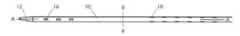
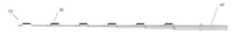
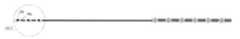
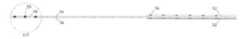
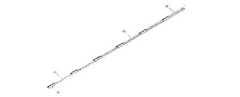
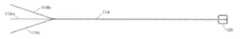
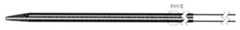
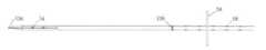
図1A、1Bおよび1Cに、例示的実施形態に係るカテーテル10の様々な図を示す。図1A、1Bおよび1Cには、カテーテル10の長手方向軸線A−Aを中心とした異なる回転位置にあるカテーテル10が示されている。カテーテル10は、押出成形ポリウレタン(または他の好適な生体適合性材料)からなる長尺状の管状部材を有している。図1Aに示すように、カテーテル10は、カテーテル10の先端部12付近において長手方向軸線に沿って並んだ一列の先端側窓16を有している。カテーテル10は、図1Cに部分的に示されている2列目の先端側窓16をさらに有している。同様に、カテーテル10において窓16よりも基端側の位置14(いくつかの実施形態においては、カテーテル10の基端)において、カテーテル10は2列の基端側窓18を有している。本明細書においては、これらの窓を「基端側窓18」と称し、基端側の組の窓18を先端側の組の窓16と区別している。他の実施形態においては、カテーテル10は3列以上の先端側窓16または3列以上の基端側窓18を有している。基端側窓18の構造的特徴は先端側窓16と同じであっても異なっていてもよい。カテーテル10の、基端側窓18と先端側窓16の間の区分には窓が形成されていない。 1A, 1B and 1C show various diagrams of the
一実施形態において、カテーテル10は、6個の先端側窓16および12個の基端側窓18を有している。しかし、他の実施形態においては、カテーテル10はこれ以上または以下の先端側窓および基端側窓を有している。例えば、他の実施形態においては、カテーテル10は2個、4個、8個、10個または12個以上の先端側窓16および/または2個、4個、6個、8個、10個または12個以上の基端側窓18を有している。先端側窓16および基端側窓18は対になるように構成されているため、カテーテル10は偶数の先端側窓16および偶数の基端側窓18を有している。しかしながら、窓16または窓18の数は奇数であってもよい。 In one embodiment, the
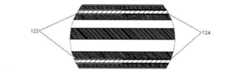
窓16,18は、カテーテル10の外壁を切除(例えばレーザー、手作業による切削、穿孔、パンチング等)することによって形成される。もしくは、押出成形中または他の製造工程において別の好適な方法によって形成してもよい。窓16,18は、長手方向軸線A−Aに沿って長尺状をなしていてもよい。窓16,18は、長方形、楕円形、正方形または他の形状であってよい。窓16,18は、電気信号がカテーテル10の内腔からカテーテル10の外側に移動できるように構成された開口部である。追加的または代替的な実施形態においては、窓16,18は、電気信号が通過できる材料によって覆われている。図に示すように、基端側窓18は、回転方向において先端側窓16からずらして配置されている。つまり、一実施形態において、先端側電極16の列を通って基端側に引かれた直線が、基端側電極18の列を通らない。別の実施形態においては、基端側電極18の1つまたは複数の列が、対応する先端側電極16の列と整合している。 The
カテーテル10の寸法は、特定の患者の解剖学的構造に合わせてカスタマイズできる。しかしながら、いくつかの実施形態においては、カテーテル10の基端側窓18を含む区分の長さは10cm以下であり、3〜5cmまたは1〜3cmである。2つの隣り合う基端側窓18(長手方向に隣り合う窓または同じ窓列において隣り合う窓)の間の距離は5cm以下であり、約1cmであってもよい。カテーテル10の先端側窓16を含む区分の長さは6cm以下であり、2〜4cmまたは1〜2cmである。2つの隣り合う先端側窓16(長手方向に隣り合う窓または同じ窓列において隣り合う窓)の間の距離は5cm以下、3cm以下または約1cmである。カテーテルにおいて、窓の形成されていない基端側窓18と先端側窓16との間の区分の長さは、12cm以下、10cmまたは8cm以下である。窓16,18の長さは6mm以下、5mm以下、4mm以下、3mm以下または1mm以下である。一実施形態において、窓の長さは、その窓を通って電気的に露出される電極の長さよりも短い。上記のカテーテルの寸法は例に過ぎず、カテーテル10は上記の範囲および特定の実寸と異なる寸法を有していてもよい。 The dimensions of the
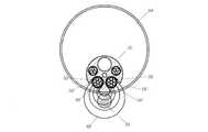
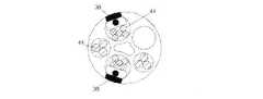
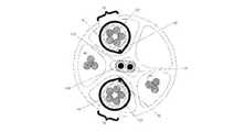
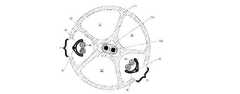
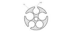
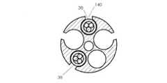
図2は、カテーテル10のII−II面(図1A)に沿った断面図である。カテーテル10の内部には1つまたは複数の管腔が形成されている。一実施形態のカテーテル10は6つの管腔20,22,24,26,28,30を有しているが、カテーテル10の管腔の数はこれより多くても少なくてもよい。管腔20,22,24,26は、以下に詳述する電極アセンブリを受容する電極アセンブリ管腔である。一実施形態において、基端側窓18は管腔20,22の内側とカテーテル10の外側との間に通路を形成している。したがって、管腔20,22は、図1A〜1Cに示す基端側窓18と整合する電極を受容する。同様に、先端側窓16は管腔24,26の内側とカテーテル10の外側との間に通路を形成し、管腔24,26は図1A〜1Cに示す先端側窓16と整合する電極を受容する。したがって、管腔20,22は基端側電極アセンブリ管腔であり、管腔24,26は先端側電極アセンブリ管腔である。詳細は後で述べるが、管腔20,22に受容される基端側電極アセンブリは患者の左横隔神経を刺激するために使用され、管腔24,26に受容される先端側電極アセンブリは患者の右横隔神経を刺激するために使用される。管腔28はガイドワイヤを受容する。管腔30は、操縦機構、他の器具またはワイヤを受容するため、または、治療部位に流体を行き来させるために使用される。 FIG. 2 is a cross-sectional view taken along the II-II plane (FIG. 1A) of the
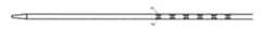
図3Aは基端側電極アセンブリ32の例示的実施形態を示し、図3Bは、単一の電極36における図3AのIIIB−IIIB面に沿った断面図である。一実施形態において、基端側電極アセンブリ32は6個の基端側電極36を有している。同様に、図3Cは先端側電極アセンブリ34の例示的実施形態を示し、図3Dは、単一の電極38における図3CのIIID−IIID面に沿った断面図である。先端側電極アセンブリ34は3個の先端側電極38を有している。2つの電極アセンブリ32および34は、電極の数、電極の構造的特徴、アセンブリ全体の構造的特徴において互いに異なっていてもよい。 FIG. 3A shows an exemplary embodiment of the proximal
1つの基端側電極アセンブリ32はカテーテルの基端側電極アセンブリ管腔20,22の一方の中に保持されており、第2の基端側電極アセンブリ32はカテーテル10の基端側電極アセンブリ管腔20,22の他方の中に保持されている。同様に、1つの先端側電極アセンブリ34はカテーテルの先端側電極アセンブリ管腔24,26の一方の中に保持されており、第2の先端側電極アセンブリ34はカテーテル10の先端側電極アセンブリ管腔24,26の他方の中に保持されている。2つの基端側電極アセンブリ32と2つの先端側電極アセンブリ34がカテーテル10の管腔内においてこのように組み合わされていることによって、12個の基端側電極36が12個の基端側窓18と整合し、6個の先端側電極38が6個の先端側窓16と整合できるようになっている。 One
図3Aおよび3Bを参照して、基端側電極アセンブリ32について詳述する。個別の電気リード44がまとめてコイル状に巻かれて基端側電極アセンブリ32のケーブル40を形成している。各リード44は長尺状の導電部材45を有し、非導電性材料の層によって囲まれている。一実施形態において、リード44はワイヤであり、長尺状導電部材45はステンレス鋼または他の導電性材料の素線を含み、非導電性材料46は絶縁層である。リード44は、電極36に電気信号または他の信号を行き来させる。 The proximal
一実施形態において、ケーブル40は7本のリード44を有している。この7本のリード44のうち、6本は特定の箇所(例えば図3Bに示すように電極36の下)においてそれぞれ絶縁が除去されており下側の導電部材45が露出している。導電コネクタ42は露出した導電部材45に結合(機械的結合、接着、マイクロ溶接等)して、ケーブル40を横方向に包囲している。導電コネクタ42は薄く、可撓性を有し、かつ、ステンレス鋼または他の導電性材料から形成されている。導電コネクタ42は、露出した導電部材45と電極36との間の接触面を構成している。一実施形態において、電極36はプラチナおよび10%のイリジウム(または、ステンレス鋼、プラチナ、窒化チタン、被覆ステンレス鋼等の他の好適な植え込み可能な電極材料)のリング電極であり、導電コネクタ42およびケーブル40の外側に圧着(または接着、マイクロ溶着)されている。図3Bの中央に示す7本目の絶縁リード44はケーブル40を支持および補強している。7本目のリード44は、センサからの信号やECG信号等の他の種類の信号を伝達するために使用してもよい。合計では、上記のように、7本のリードを有する基端側電極アセンブリがカテーテル10の管腔20,22内に2つ挿入されている。 In one embodiment, the
図3Cおよび3Dに示すように、先端側電極アセンブリ34のケーブル48は3本の電気リード44を有している。これらのリードは、基端側電極アセンブリ32において説明した構成と類似の構成を有している。3個の電極38が導電コネクタ42に装着されており、導電コネクタ42は対応するリード44の露出した導電部材45に接続されている。追加的または代替的な実施形態においては、リング電極36,38の代わりに部分的に円状または半円状の電極が用いられる。カテーテル10内の管腔の数、ケーブル40,48の数、各ケーブル40,48上の電極36,38の数、電極36,38間の距離および他の構造的特徴は、特定の用途に応じて異なる。 As shown in FIGS. 3C and 3D, the
一実施形態においては、基端側電極36または先端側電極38のいずれかが、患者体内からの電気信号や他のデータを測定するために使用される。つまり、電極は、神経刺激をもたらす局所電流を生成するために電気エネルギーを放出または受容することに加えて、またはこの代わりに、患者から電気的または他の種類の情報を受けるセンサとして機能することができる。 In one embodiment, either the
図4A〜4Dに、複数の電極アセンブリ32,34がカテーテル10の管腔内に収められている状態を示す。図4Aはカテーテル10を示し、図4Bは2つの基端側電極アセンブリ32を示し、図4Cは2つの先端側電極アセンブリ34を示す。2つの基端側電極アセンブリ32は、電極36が基端側窓18と整合するようにカテーテル10の管腔20,22内に配置される。同様に、2つの先端側電極アセンブリ34は、電極38が先端側窓16と整合するようにカテーテル10の管腔24,26内に配置される(図4Aには示されていない)。整合された電極アセンブリ32,34は、各カテーテル管腔内において固定される(例えば接着材や他の構造または方法によって固定される)。図4Dは、カテーテル10の図4AのIVD−IVD面に沿った断面図である。カテーテル10の管腔20,22,24,26内には2つの基端側電極アセンブリ32および2つの先端側電極アセンブリ34が配置されている。 4A-4D show a state in which a plurality of
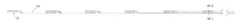
図5を参照して、医療器具50は、2つの基端側電極アセンブリ32および2つの先端側電極アセンブリ34を有するカテーテル10を備えている。電極アセンブリ32,34は、電極36が基端側窓18を介して露出し、電極38が先端側窓16を介して露出するようにカテーテル10の長尺状の管状部材内に配置される。電気リード44によって構成されるケーブル40,48は、カテーテル10の基端から出てコネクタ52,54に装着される(例えばはんだ付け、圧着、PCB等により装着される)。 With reference to FIG. 5, the
医療器具50の組み立て時には、リード44および電極36,38を有する電極アセンブリ32,34が、カテーテル10の基端または先端の管腔開口を介して1つまたは複数の管腔内に導入される。例えば、リード44がカテーテル10の基端に挿入され、電極36,38がカテーテル10のさらに先端側の部位の所定位置に配置されるまで1つまたは複数の管腔内に通されるか、管腔を通って引かれる。電極アセンブリ32,34の挿入前または挿入後に、カテーテル壁の一部が除去されて窓16,18が形成される。窓16,18を介して電極が露出することによって、医療器具50が配置される血管の管腔と電極36,38との間に導電路が形成される。 During assembly of the
図5を引き続き参照して、例示的な使用方法において、ヒトまたは他の哺乳類(豚やチンパンジー等)の頸部および/または胸部の神経に対して経血管的に刺激を加えるために医療器具50が使用される。図5は、ヒトの頸部および胸部の選択された神経および血管の構造を示し、具体的には、左横隔神経(PhN)56、右横隔神経58、迷走神経(VN)(図示しない)、外頸静脈または内頸静脈(JV)60、腕頭静脈(BCV)62、上大静脈(SVC)64および左鎖骨下静脈(LSV)66の相対位置を示している。 With reference to FIG. 5, in an exemplary use, a
医療器具50は、1つまたは複数の電極アセンブリ32,34を有するカテーテル10を患者の中心静脈内に経皮的に挿入することによって横隔膜を律動的に動かすために用いられる。カテーテル10の経皮的挿入はセルジンガー法によって行われ、皮下注射針を介してガイドワイヤが静脈内に挿入される。次に、カテーテルの先端がガイドワイヤ上を移動して静脈内に進められる。カテーテルの形状および機械的特性は、図5に示すように、カテーテル10が左右の横隔神経に近い静脈壁の領域にかるく沿うようにカテーテル10が付勢されるように設計されている。 The
図5の実施形態においては、医療器具50は左鎖骨下静脈66に挿入されて上大静脈64内に移動されている。図示しない別の構成においては、医療器具50は左頸静脈に挿入されて上大静脈64内に移動されている。カテーテル10は低侵襲手法によって患者体内に挿入されて一時的に配置され、患者体内から除去可能である。一実施形態において、カテーテルが左鎖骨下静脈66内に挿入されたときに、6対の窓18が左横隔神経56の後方に向かって配置され、3対の先端側窓16が右横隔神経58に対して横方向に向かうように窓18が配向される。 In the embodiment of FIG. 5, the
一実施形態において、電極アセンブリ34は、カテーテル10と平行に延びる神経(図5の右横隔神経58等)を最も効果的に刺激するために配置および配向された電極38を含み、電極アセンブリ32は、カテーテル10を横切る方向またはカテーテル10と直角方向に延びている神経(図5の左横隔神経56等)を最も効果的に刺激するために配置および配向された電極36を含む。追加的または代替的な実施形態においては、電極アセンブリ34は、カテーテル10を横切る方向またはカテーテル10と直角方向に延びている神経を最も効果的に刺激するよう配置または配向された電極38を有し、電極アセンブリ32は、カテーテル10と平行に延びる神経を最も効果的に刺激するよう配置および配向された電極を有している。上記の実施形態においては、電極アセンブリ34の電極38は、カテーテル10に沿って電極アセンブリ32の電極36よりも先端側の位置に配置されている。しかし、他の実施形態においては、電極アセンブリ32の電極36が電極アセンブリ34の電極38よりも先端側に位置するように電極アセンブリ32がカテーテル10内に配置される。この代替的実施形態においては、カテーテル10の窓16,18が、電極アセンブリ32,34の代替的配置を可能にするように構成される。 In one embodiment, the
カテーテルが患者体内に完全に挿入されると、バイポーラ電極の組み合わせのいくつかの対をテストして、対象の神経の位置を特定するとともに、どの電極が最も効果的に対象神経を刺激するかを判断する。例えば、一実施形態においては、右横隔神経58の位置を特定するとともに、右横隔神経58を最も効果的に刺激するのは(先端側の組の電極38のうちの)どの対の電極38なのかを特定するためにテストが行われる。同様に、左横隔神経56の位置を特定するとともに、左横隔神経56を最も効果的に刺激するのは(基端側の組の電極36のうちの)どの対の電極36なのかを特定するためにテストが行われる。非限定的な例においては、選択された電極に電気的刺激を規則的に送る信号生成器を用いてテストが行われる。患者の容体を観察することやセンサを使用することによって、好適な電極対を特定する。 Once the catheter is fully inserted into the patient's body, several pairs of bipolar electrode combinations are tested to locate the target nerve and which electrode most effectively stimulates the target nerve. to decide. For example, in one embodiment, which pair of electrodes (among the apical pair of electrodes 38) is most effective in stimulating the right
図6Aは、図4AのVIA−VIA面に沿ったカテーテル10の断面図である。図6Aを参照して、神経刺激のために一対の電極を選択的に作動させることについて説明する。図6Aの電極は、カテーテル10に沿った任意の箇所に位置する任意の対の電極であってよく、神経56は、カテーテル10に対して、平行や交差等のいかなる向きに配置された神経であってよい。しかしながら、説明を容易にするために、図5では左横隔神経56はカテーテル10と交差しているが、図6Aに関しては基端側電極36および左横隔神経56を参照する。図6Aには示されていないが、一対の先端側電極38も右横隔神経58を刺激するために選択的に作動される。 FIG. 6A is a cross-sectional view of the
「選択的作動」においては、選択された一対のバイポーラ電極の間、例えば第1電極36’と第2電極36’’との間に電位が生じる。第1電極36’は第1窓18’と整合し、第2電極36’’は第2窓18’’と整合している。第1および第2電極36’,36’’および第1および第2窓18’,18’’をこのように配置することによって、第1および第2窓18’,18’’の近傍に電界68が形成される。第1および第2電極36’,36’’が、図6Aに示す左横隔神経56や、電極36’,36’’の近くの他の神経等に効果的に刺激を与えるために選択される。窓18’,18’’および生じる電界68は、左横隔神経56または他の標的神経に向かうように配置されている。 In "selective operation", a potential is generated between the pair of selected bipolar electrodes, eg, between the first electrode 36'and the second electrode 36'. The
神経刺激時には、電流が電極36’,36’’の一方から他方に流れ、窓18’,18’’を通って流れて、血液および周囲組織に流れる。窓18’,18’’を有するカテーテル10は、電界68を制限して集中させる絶縁バリアとして機能するため、電界68が径方向外側に向かって全方位に拡張することが抑制される。電界を集中させることにより、標的神経の刺激を低いエネルギーレベルにて行うことができ、対象以外の神経や他の構造に刺激が加わることが避けられる。いくつか実施形態においては、刺激用電流は10〜6000nC(ナノクーロン)または50〜500nCである。 During nerve stimulation, an electric current flows from one of the
図6Bに、神経78の刺激に用いられる従来例の神経刺激器具70を示す。従来器具70は、リードワイヤ72および電極74を有している。器具70は血管76に挿入され、器具70の周囲に電界80が形成される。図6Bに示すように、電界80は器具70の外周の周囲に形成される。この電界は、神経78を標的としているとはいえ、特定の位置に制限されておらず、患者体内の他の解剖学的構造にも刺激を与えている。通常の場合、カテーテル10の窓16,18によって、より少量かつ安全な電流を用いて横隔神経56,58を励起することができ、過度の刺激や、他の神経、筋肉または心臓等の近傍構造に対する不要な刺激を抑制できる。 FIG. 6B shows a
(電極アセンブリ実施形態)
図7A〜13Kに、本明細書に記載する各カテーテルとともに使用できる電極および電極アセンブリの追加的または代替的な実施形態を示す。以下に記載する実施形態は、上記の電極アセンブリおよび電極の変更例である。したがって、言及されない特徴については変更されていないか、上記の実施形態に対して適宜変更が加えられている。参照を容易にするために、各実施形態の基端側電極36、基端側電極アセンブリ32、先端側電極38および先端側電極アセンブリ34には、その特徴のいくつかが下記の実施形態において変更されている場合でも、上記と同じ符号が付されている。(Electrode assembly embodiment)
7A-13K show additional or alternative embodiments of electrodes and electrode assemblies that can be used with each of the catheters described herein. The embodiments described below are modifications of the above electrode assembly and electrodes. Therefore, features not mentioned have not been changed, or have been appropriately changed from the above embodiments. For ease of reference, the
(裸/縫いワイヤ)
図7A〜7Dに示すように、リード44の一部から非導電性材料46の層を除去し、下側の導電部材45を露出させてもよい。図7Aはカテーテル10を示し、図7Bは基端側電極アセンブリ32を示す。リード44の露出した導電部材45(直線状または表面積を増やすためにコイル状になっている)はカテーテル10の窓16,18内に配置され、いくつかの実施形態においては、窓16,18から径方向外側に延びている。別の実施形態においては、図7Cに示すように、導電部材45はカテーテル外壁の開口部からカテーテル10の管腔を出て基端側−先端側方向に移動して、カテーテル10の別の開口部から管腔内に戻っている。電極36,38を形成している導電部材45の部分は、リード44の先端であってもよい。追加的または代替的に、絶縁リード44はカテーテル10に縫い込まれ、露出した導電部材45はカテーテル10の外側に配置され、残りの絶縁リード44はカテーテル管腔内に配置される。図7Dは、カテーテル10の、露出した導電部材45を有する一対の基端側電極36を通る断面図である。(Nude / sewing wire)
As shown in FIGS. 7A-7D, the layer of the
いくつかの実施形態において、図10A〜10Eを参照して説明される電極等の導電部材がカテーテル10の外側に固定され(例えば、接着、熱溶着等により固定される)、露出した導電部材45と電気的に接触する(例えば機械的手段、マイクロ溶接によって接触する)。このような導電部材を露出した導電部材45に固定することによって、露出した導電部材45のみを有する電極と比較して、導電性や表面積等の、電極の特定の電気的特性が向上する。導電部材の材料としては、プラチナ、プラチナ・イリジウム、金、ステンレス鋼、窒化チタン、MP35N、パラジウム等が挙げられる。 In some embodiments, a conductive member such as an electrode, described with reference to FIGS. 10A-10E, is fixed to the outside of the catheter 10 (eg, fixed by adhesion, heat welding, etc.) and exposed
(プリント電極)
図8Aに、カテーテル10の外側に直接プリントされた電極およびリードを有するカテーテルを示す。図8Bは、カテーテル10の先端側電極38の分解図であり、図8Cはカテーテル10の基端側電極36の分解図であり、図8Dは図8CのVIIID−VIIID面に沿った基端側電極対36の横断面図である。電極36,38は導電性インク(ポリマー内に懸濁する銀フレークまたは炭素フレーク)により形成される。これらの導電性インクは、カテーテル10に直接載置されて接着され、露出した電極36,38を除いて、外側ポリウレタンフィルムまたは他の可撓性および絶縁性を有するフィルムによって封止される。露出した電極36,38も、導電性や表面積等の電気的特性の向上、耐食性の付与、有毒となりえる銀酸化物形成の可能性の低減等の目的のいくつかを満たすために被覆される(例えば窒化チタンで被覆される)。図8Cに示すように、先端側電極38の導電性インクトレースは、カテーテル10に沿って基端側電極36を越えて基端側に延びる。(Printed electrode)
FIG. 8A shows a catheter with electrodes and leads printed directly on the outside of the
プリントされた電極を使用することによって、カテーテルの寸法または可撓性を大幅に変更することなく、設計の全体的な複雑度を低下させ、使用できるカテーテル管腔のスペースを最大化できる。しかしながら、いくつかの実施形態においては、カテーテル外側にプリントされた電極を使用することによってスペースが節約されるため、カテーテルの寸法が小さくされる。追加的または代替的な実施形態においては、1つまた複数のカテーテル管腔が流体搬送、採血または中心静脈圧の監視のために使用される。別の追加的または代替的な実施形態においては、他の実施形態において記載したカテーテルアセンブリが存在しないため、管腔20,22,24,26等の複数のカテーテル管腔が省略される。したがって、一実施形態においては、カテーテル10は管腔28および管腔30のみを有している。例えば、プリントされた電極を有するカテーテル10が図2に示す6個の管腔よりも少ない管腔を有している場合は、カテーテル10の断面積を小さくしてもよいし、数が少なくなった管腔のうちの1つまたは複数を大きくして大型の器具や他の物体を受容できるようにしてもよい。もしくは、器具または他の物体を受容するための1つまたは複数のより小さい管腔を追加してもよい。 By using the printed electrodes, the overall complexity of the design can be reduced and the available catheter lumen space can be maximized without significantly changing the dimensions or flexibility of the catheter. However, in some embodiments, the size of the catheter is reduced because space is saved by using electrodes printed on the outside of the catheter. In additional or alternative embodiments, one or more catheter lumens are used for fluid delivery, blood sampling or monitoring of central venous pressure. In another additional or alternative embodiment, multiple catheter lumens such as
(電極支持カテーテル)
図9A〜9Eに、カテーテル10の管腔内に配置されたカテーテル94,96に支持された電極36,38を示す。この実施形態においては、基端側電極36は電極カテーテル94に接合され、先端側電極38は電極カテーテル96に接合されている。カテーテル94,96は、非導電性材料を含む長尺状の管状部材である。電極36,38はカテーテル94,96に圧着されて、電極カテーテル94,96の壁を介してリード44の導電部材45に電気的に接続されている。カテーテル94,96の断面積は、カテーテル10の対応する管腔の断面積よりも小さく、カテーテル10の管腔にカテーテル94,96を挿入できるようになっている。カテーテル94,96がカテーテル10に挿入されると、他の実施形態と同様に、電極36,38がカテーテル10の窓16,18と整合されてその位置に固定される。図9Eには示されていないが、リード44は電極カテーテル94,96内を基端側−先端側方向に移動する。(Electrode support catheter)
9A-
追加的または代替的な実施形態においては、単一の電極36もしくは38または一対のバイポーラ電極を有する1つまたは複数のカテーテルが、処置中(すなわち、カテーテル10が患者の血管系内にあるとき)にカテーテル10の管腔内に挿入され、最適な位置が見つかるまでいくつかの窓16,18に向かって移動する。これにより材料を減らすことができ、その結果、医療器具50の製造コストを低減できる。 In additional or alternative embodiments, one or more catheters with a
(外側電極)
図10A〜10Eは、カテーテル10の外側に配置された電極36,38を示す。図10A〜10Eの実施形態においては、電極36,38はリード44に接続(マイクロ溶接等)されてカテーテル10の外側に固定(圧着、接着等)される。リード44はカテーテル10の壁を通って(例えば窓16,18を通って)挿入され、カテーテル10の管腔内に入る。(Outer electrode)
10A-
別の実施形態においては、1つまたは複数のリング電極がカテーテル10の外側に固定される。1つまたは複数の神経に対して方向の照準を合わせやすくするために、電極の一部は絶縁コーティングによって覆われている。 In another embodiment, one or more ring electrodes are secured to the outside of the
(射出成形)
図11A〜11Fに、電極アセンブリ32,34の製造工程に射出成形が含まれる実施形態を示す。電極を図11Bおよび11Cに示すように構成するために、電極36,38が射出成形によってリード44に個別に装着される。電極36,38は、導電部材45と電気的に接触している。この成形工程において、各リード44の周囲に被覆部98が形成される。被覆部98はプラスチック等の非導電性材料を含んでいる。電極36,38は平坦状、半円状、または他の好適な形状を有している。同様に、被覆部98は、リード44の周囲において、例えば図11Fに示す形状のような、いかなる形状を有していてもよい。(injection molding)
11A-11F show embodiments in which injection molding is included in the manufacturing process of the
図11Dおよび11Eに示す別の実施形態においては、電極36,38および束になったリード44が、成形治具内に配置される。成形治具からプラスチック等の材料がリード44の束の周囲に射出されることによって、電極が所定の位置に固定されて被覆部98が形成される。但し、一実施形態においては、電極38の少なくとも一部が露出した状態に維持される。いくつかの実施形態において、電極は薄いポリマー層によって被覆され、この層は後の工程において除去される。図11Cに示す実施形態においては、被覆部98は電極の長手方向における近傍のみに配置され、単一のリードのみを包囲しているため「部分的」と表現される。図11Eの実施形態においては、被覆部98は下側のリード44より大きい長手方向範囲を覆い、複数のリードを包囲しているため、「全体的」と表現される。各電極38がリード44に固定された後に、電極アセンブリ32,34がカテーテル10の管腔内に挿入されて窓16,18と整合される。 In another embodiment shown in FIGS. 11D and 11E, the
(管状部材に支持された電極)
図12A〜12Kに、電極アセンブリ32,34のさらに別の実施形態を示す。この実施形態においては、管状部材100がリード44の先端102を支持し、電極36,38の近傍において先端102を保持している。(Electrodes supported by tubular members)
12A-12K show yet another embodiment of the
図12Aはカテーテル10を示す。図12Bは先端側電極アセンブリ34の斜視図である。図12Cは基端側電極アセンブリ32の斜視図である。図12Dは、図12Bの先端側電極アセンブリ34の側面図である。図12Eは、図12Cの基端側電極アセンブリ32の側面図である。図12Fは12Dの先端側電極38の横断面図である。図12Gは12Eの基端側電極36の横断面図である。図12Hは、図12Bの2つの先端側電極アセンブリ34がカテーテル管腔内に収められた状態を示す、図12Aのカテーテルの横断面図である。図12Iは、図12Cの2つの基端側電極アセンブリ32がカテーテル管腔内に収められた状態を示す、図12Aのカテーテル10の横断面図である。図12Jは、ECGワイヤがカテーテル10の中心管腔内に収められた状態の図12Hのカテーテルを示す。図12Kは、ECGワイヤがカテーテル10の中心管腔内に収められた状態の図12Iのカテーテルを示す。 FIG. 12A shows the
図12B〜12Gに、基端側電極アセンブリ32の基端側電極36および先端側電極アセンブリ34の先端側電極38を示す。図に示すように、電極アセンブリ32,34は、他の実施形態と同様にリード44を有している。図12Fおよび12Gに明確に示されているように、リード44の先端部102は、露出した導電部材45を有し、溶接等の方法によって管状部材100の外側および電極36,38の内側に取り付けられている。管状部材100の長さは1〜6mm、2〜4mm、一実施形態においては約3mmであるが、他の適宜な長さであってもよい。管状部材100は、ステンレス鋼の皮下チューブである。(図12B〜12Eにおいては、管状部材100は見えておらず、そのすべてまたは大部分が電極36,38に覆われている。リード44の先端部102は図12Dおよび12Eにおいて大まかな位置を示すために符号が付されているが、先端部102は電極36,38の下側に位置している。)図12Fおよび12Gに示すように、リード44の先端部102によって、電極36,38は径方向外側に突出している。 12B to 12G show the
各リード44は、そのリードの先端102が取り付けられた電極よりも基端側に位置する電極36,38を通って基端側に移動する。例えば、図12Bを参照して、先端側電極アセンブリ34の最も先端側の電極38に装着されたリード44は、他の2つの電極38および6個の基端側電極36すべてを通って基端側に移動する。図12Cを参照して、最も先端側の電極36に装着されたリード44は他の5つの電極36のすべてを通って基端側に移動する。 Each lead 44 moves to the proximal end side through
一実施形態において、先端側電極アセンブリ34は3本のリード44を有し、各リード44はそれぞれ各電極38に対応している。同様に、基端側電極アセンブリ32は6本のリード44を有し、各リード44はそれぞれ各電極36に対応している。各電極アセンブリ32,34のリード44が結合されるときに、リードが巻かれてケーブル48,40を形成する。より先端側の位置においては、ケーブル48(先端側電極アセンブリ34からのリード44によって形成されるケーブル)は1本または2本のリードを含む。より基端側の位置、例えば最も基端側の電極38より基端側の位置においては、ケーブル48は3本のリード44を含む。同様に、より先端側の位置においては、ケーブル40(基端側電極アセンブリ32からのリードによって形成されるケーブル)は1本、2本、3本、4本または5本のリードを含む。より基端側の位置、例えば最も基端側の電極36より基端側の位置においては、ケーブル40は6本のリード44を含む。 In one embodiment, the
図12Hおよび12Iは、カテーテル10の管腔内に収められた電極アセンブリ32,34の断面図である。図12Hおよび12Iに示されるカテーテル10は図2の形状とは異なるが、このカテーテル10も、基端側電極アセンブリ32を受容するように構成された管腔20,22と、先端側電極アセンブリ34を受容するように構成された管腔24,26と、ガイドワイヤを受容するように構成された管腔28と、操縦機構または他の構造を受容するように構成された管腔30とを有している。図12Hに示すように、先端側電極38は先端側窓16と整合している。図12Iには、基端側窓18と整合する基端側電極36が示されている。先端側電極アセンブリ34からのリード44は管腔24,26を通って基端側に延びているので、図12Iの断面図に示されている。 12H and 12I are cross-sectional views of the
図12Jおよび12Kは図12Hおよび12Iに似ているが、図12Jおよび12Kにおいては管腔30内に2つの心電図記録(ECG)導電部材104が示されている点で相違している。ECG導電部材104は、患者のECG信号を感知するためにカテーテル10の先端に位置する1つまたは複数のECG電極106(図12Aおよび14)に連結されている。 12J and 12K are similar to FIGS. 12H and 12I, except that in FIGS. 12J and 12K two ECG
図12A〜12Kに示す実施形態の利点としては、各電極36,38が他の電極36,38に対して移動可能であることが挙げられる。リード44は電極36,38に接続されているが、リード44は一般的に可撓性を有している。したがって、本実施形態においては、医療器具50の製造時にカテーテル10内に電極アセンブリ32,34を置くときに、少なくとも部分的に他の電極から独立して、対応する窓16,18に各電極36,38を配置することができる。電極を独立して配置できることによって、電極36,38がカテーテルや他の剛性構造によって他の電極に固定されている実施形態と異なり、位置決めの誤差が抑えられる。 An advantage of the embodiments shown in FIGS. 12A to 12K is that each
(円弧状電極)
図13A〜13Kに、図12A〜12Kに示す実施形態に類似した実施形態を示す。図12A〜12Kの実施形態と類似する特徴については説明を省略する。図13A〜13Kの実施形態と図12A〜12Kの実施形態の主な相違点は、図13A〜13Kの各電極36,38は円弧状であるため、リード44の先端102(露出した導電部材45を含む)を保持して接触できるようになっている点である。図13A〜13Kの基端側および先端側のアセンブリ32,34は管状部材100を有していても有していなくてもよい。(Arc-shaped electrode)
13A to 13K show embodiments similar to the embodiments shown in FIGS. 12A to 12K. Descriptions of features similar to those of the embodiments shown in FIGS. 12A to 12K will be omitted. The main difference between the embodiments of FIGS. 13A to 13K and the embodiments of FIGS. 12A to 12K is that the
図13Fおよび13Gに示すように、各電極36,38はC字状をなして、外壁108および内壁110を有している。電極の外壁108および内壁110は、リード44の先端102において露出した導電部材45を挟んでいる。 As shown in FIGS. 13F and 13G, the
(心電図記録電極)
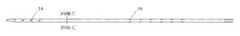
図14に、2つのECG電極106および関連する部材を示す。本明細書における他の全特徴と同様に、ECG電極106は本明細書に記載する他の実施形態と共に用いることができる。ECG電極106はカテーテル10の先端に配置される(図12A)。一実施形態においてはカテーテル10が2つのECG電極106を有しているが、いくつかの実施形態のカテーテル10は1つの電極106または2つよりも多い電極106を有している。各電極106は、絶縁された導電部材104によって患者の体外に配置されたECGシステムに接続されている。ECG導電部材104はまとめて編組または撚合されており、非導電性層105(図12Jおよび12Kにも示されている)に覆われている。(Electrocardiography recording electrode)
FIG. 14 shows the two
電極106は患者の心拍を監視する。心拍の監視は、医療器具50使用中の患者の心拍の変化を医療スタッフに警告できるため有益である。患者の心拍の変化は、医療器具50による特定の神経に対する刺激や、患者の心臓に対する意図しない刺激によって生じている可能性もある。また、心拍の監視は、神経の安定した活性化を達成するためにも役立つ。例えば、カテーテル10は患者の心臓が脈動したときに動くため、神経刺激に変動が生じる。患者の拍動がわかっていれば、一対のバイポーラ神経刺激電極の間に生成される電位をリアルタイムで調節でき、神経に一定の電荷を届けることができる。
(操縦機構)
血管内においてカテーテルの窓16,18および電極36,38の位置決め制御を補助するために、様々な操縦機構を医療器具50に配置することができる。操縦機構はカテーテル10の中心管腔30またはカテーテル10の他の管腔内に配置される。少なくともいくつかの電極36,38を各標的神経のすぐ近くに配置することが好ましい。神経の近くに電極を置くことによって、血液を介して分流する電流が減り、神経の活性化に要する電流を低減できる。(Maneuvering mechanism)
Various maneuvering mechanisms can be placed on the
血管内の所望の位置への基端側窓18の配置を助ける要素はいくつかある。例えば、通常の鎖骨下静脈貫入角度とカテーテル10の形状および弾性とを適宜組み合わせることによって、基端側窓18を鎖骨下静脈の後壁に沿って、左横隔神経のすぐ近くに配置することができる。通常の場合、左横隔神経は左鎖骨下静脈の背面側において下方に延びている。 There are several factors that aid in the placement of the
窓16および対応する電極38を含んだカテーテル10の先端部が右横隔神経に対して所望の位置に確実に配置されるように、医療器具50は補強要素および操縦機構を備えていてもよい。一実施形態において、補強要素および操縦機構は、右横隔神経の近傍において上大静脈の外側壁に対する先端側の組の電極38の位置決めを補助する。 The
(回転部材操縦機構)
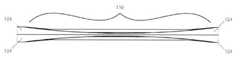
図15A〜15Cに示すように、操縦機構112は、カテーテル10を操縦するワイヤまたはチューブ(例えばステンレス鋼皮下チューブやニチノール皮下チューブ)等の、予備成形された単一の長尺状部材114を有している。長尺状部材114はハンドル120と、ハンドル120に連結された基端部116と、基端部116に対して屈曲している先端部118とを有している。基端部116がハンドル120を介して回されると、先端部118がこれに応じて様々な位置に回転され、カテーテル10の先端を位置決めするよう機能する。(Rotating member control mechanism)
As shown in FIGS. 15A-15C, the
図15A〜15Cに、3つの異なる位置に配置された長尺状部材114を示す。先端部118aは第1の位置にあり、先端部118bは第2の位置にあり、先端部118cは第3の位置にある。図15Aは、3つの異なる位置に配置された操縦機構112の正面図であり、図15Bは3つの異なる位置に配置された操縦機構112の上面図であり、図15Cは、3つの異なる位置に配置された操縦機構112を操縦機構112の先端から操縦機構112の基端に向かって見た図である。 15A-15C show the
長尺状部材114は、先端側電極38を含んだカテーテル10の先端部が血管壁に確実に当接できる剛性を有している。また、長尺状部材114は、基端側ハンドル120から先端部118へ操縦トルクを伝達できる剛性を有している。 The
(制御部材操縦機構)
図16A〜16Eに、1つまたは複数の制御部材122を含む他の実施形態の操縦機構112を示す。一実施形態において、制御部材122はカテーテル10の一部を屈曲また湾曲させるために引いたり押したりされる。制御部材122は、皮下チューブまたは圧縮コイル等の1つまたは複数の管状部材124によって包囲され、管状部材124に対して長手方向にスライドする。管状部材124は可撓性を有している。本実施形態の操縦機構112は、管状部材124に装着(溶接、接着等)されたチューブやロッド等の補強要素126をさらに有している。(Control member control mechanism)
16A-16E show the
図16A〜16Eの実施形態においては、カテーテル10の双方向の操縦が可能である。操縦機構112の基端において、それぞれ対応する管状部材124に対して制御部材122を押すまたは引くためのハンドル(図示しない)が配置されている。図16Cに示すように、操縦アセンブリ112の先端において、管状部材124の間に隙間128が形成されている。この隙間28によって、カテーテル10の先端の屈曲が容易になる。組み立て後には、操縦機構112は中心管腔30またはカテーテル10の他の管腔に接着される。 In the embodiments of FIGS. 16A-16E, bidirectional maneuvering of the
図17Aおよび17Bに、管状部材124が狭窄部130を有している、追加的または代替的な実施形態を示す。狭窄部130は、所望の可撓性をもたらすように、隙間128の代わりに形成してもよいし、隙間128と組み合わせて用いてもよい。狭窄部130はレーザー等の方法によって形成される。 17A and 17B show additional or alternative embodiments in which the
図18A〜18Eを参照して、操縦機構112のさらに別の実施形態においては、制御部材122がカテーテル10の異なる管腔132,134内に配置される。図16A〜16Eの実施形態と同様に、制御部材122は、皮下チューブまたは圧縮コイル等の1つまたは複数の管状部材124に包囲されている。一実施形態においては、各管状部材124は対応する制御部材122の先端部を包囲しておらず、制御部材122の先端部は対応する管腔132、134の先端に固定されている。各管状部材124の先端部も、制御部材122の固定位置よりも基端側の位置において対応する管腔132,134に固定されている。制御部材122の固定部分と、対応する管状部材124の固定部分との間には管腔に沿って長手方向に延びる隙間が形成されている。このため、制御部材122が管状部材124に対して押されるか引かれた場合、隙間スペース内においてカテーテル10が湾曲する。 With reference to FIGS. 18A-18E, in yet another embodiment of the
図19A〜19Eに、操縦機構112が単一の制御部材122を有しているさらに別の実施形態を示す。制御部材122は管状部材124に包囲されて、カテーテル10の先端を湾曲させるために管状部材124に対して押し引きされる。制御部材122の先端部は、管腔30またはカテーテル10の他の管腔の先端内に固定され、管状部材124は、管腔30内のより基端側の位置に固定される。ここでも、カテーテル10の湾曲位置を制限するために、制御部材122の固定部分と管状部材124の固定部分との間に隙間が形成される。一実施形態においては、制御部材122が引かれることによってカテーテル先端が一方向に湾曲し、制御部材122が押されることによってカテーテル先端が反対の方向に湾曲される。 19A-19E show yet another embodiment in which the
いくつかの実施形態においては、前述の操縦機構がバルーンを有している。バルーンが膨張することによって、上大静脈外側壁に対するカテーテル10の先端部および先端側電極38の付勢が補助される。バルーンは、先端側電極38に対応する窓とは反対側のカテーテル側面に装着される。バルーンが膨張すると、電極38は上大静脈壁に向かって付勢される。 In some embodiments, the maneuvering mechanism described above comprises a balloon. The inflating of the balloon assists in urging the distal end of the
(カテーテル実施形態)
(カテーテル窓構成)
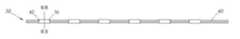
図20A〜20Cを参照して、カテーテル10の窓16,18については様々な代替配置が可能である。例えば、図1に示すように整列しているのではなく、カテーテル10の外面の基端−先端線136またはカテーテル10の外周上の周方向線138を基準として、窓16は別の窓16からずらして配置されていてもよく、窓18は別の窓18からずらして配置されていてもよい。例えば、より基端側の窓16が、最も先端側の窓16の中心を通って延びる一本の基端−先端線136上に位置していないときは、窓16は互いにずらして配置されている。図20Bおよび20Cの各窓18は、窓18の中心を通って延びる周方向線138を基準にして、他の窓18からずらして配置されている。カテーテル10の実施形態においては、窓16,18はずらされた窓およびずらされていない窓をいかなる組み合わせにて構成することができる。前述したように、一組の窓16または窓16の列は、基端−先端線136を基準として、一組の窓18または窓18の列からずらされていてもよい。(Catheter embodiment)
(Catheter window configuration)
With reference to FIGS. 20A-20C, various alternative arrangements are possible for the
神経の近くに電極を配置することに加えて、窓16,18によって決定される、神経に対する電極の構成によっても、神経の軸索を刺激するために必要な電流量を低減させることができる。電極および電流の流れ方向が神経に平行であるか神経に沿っている場合は、より小さい電流で神経軸索を活性化でき、活動電位を生成できる大きさの経膜脱分極が発生する。神経経路の方向は正確には分かっておらず、個体によって異なる。 In addition to placing the electrodes near the nerve, the configuration of the electrodes to the nerve, as determined by the
複数の異なる電極構成が可能であるため、神経刺激に使用する電極の組を各個体に対して選択できる。例えば、基端側電極36については、神経を効果的に刺激するように、カテーテル10の周方向において電極対が直線状(例えば図20Aのように周方向線138に沿った直線状)、互い違い(例えば図20B)または角度をなして(例えば図20C)配置される。図20Aを参照して、周方向線138は2つの電極の中心(もしくはその上)を通っていてもよいし、2つの電極の別の部分(もしくはその上)を通っていてもよい(例えば、電極対は若干ずれていてもよい)。図20Bを参照して、互い違いに配置された電極対は、長手方向に隣り合う電極の間(電極18aと電極18bの間等)の長手方向距離(カテーテル10の長手方向軸線に平行な基端−先端線に沿った距離)が、長手方向に隣り合う他の電極対(例えば電極18bおよび電極18c)の間の長手方向距離と略同じになるように配置される。図20Cを参照して、角度をなして配置された電極対は、電極対の中心を通る平面がカテーテル10の長手方向軸線に対して直交しないように配置される。図20Bの互い違いの電極の実施形態は、図20Cの角度をなして配置された電極の実施形態の一部である。また、周方向線38が電極対の中心以外の部分もしくはその上を通っている図20Aの実施形態も、角度をなして配置された電極対とみなすことができる。電極構成は、各患者の解剖学的な相違に応じて、カテーテル10に沿って変化させることができる。適切な電極対を選択することによって、患者間の相違があっても効果的な神経刺激を実施できる。 Since a plurality of different electrode configurations are possible, the set of electrodes used for nerve stimulation can be selected for each individual. For example, with respect to the proximal
(予備成形されたカテーテル)
図21に、本明細書に開示された実施形態による電極36,38を有する、予備成形されたカテーテル10を備える医療器具50を示す。予備成形されたカテーテル10は、円弧状、コイル状、S字状、U字状または他の予備成形された部分を有している。予備成形されたカテーテル10は、右横隔神経の経路が通常よりも前方または後方に位置している患者であっても、電極36,38が血管壁に密接して横隔神経または他の神経の近くに確実に配置されるように機能する。(Preformed catheter)
FIG. 21 shows a
カテーテル10は、例えば、カテーテル管腔内に補強要素を挿入することによって予備成形できる。または、製造工程中に予備成形してもよい。予備成形されたカテーテル10は、可撓性を有しつつも若干の剛性を備えており、予備成形された形状に戻る傾向を有している。より剛性の高いガイドワイヤ上に配置されて挿入される際には、カテーテル10が直線状になるため挿入が容易になる。ガイドワイヤが取り出されると、カテーテル10は、予備成形された形状に戻る。 The
(長尺状間隙を有するカテーテル)
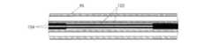
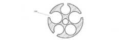
図22A〜24Bを参照して、追加的または代替的な実施形態においては、カテーテル10の外側に沿って長尺状間隙140が形成される。長尺状間隙140はカテーテル10の外側と内腔とを接続し、スリットまたは経路とも称される。図22Aおよび22Bに示すように、長尺状間隙140はカテーテル10の全長にわたって延びていてもよい。追加的または代替的に、図23Aおよび23Bに示すように、長尺状間隙140はカテーテル10の全長の一部のみにわたって延びていてもよい。図24Aおよび24Bに示すように、長尺状間隙140は追加的または代替的にスリーブ142によって覆われていてもよい。(Catheter with long gap)
With reference to FIGS. 22A-24B, in an additional or alternative embodiment, an
カテーテル10の管腔の長さおよび小径に起因して、医療器具50の組み立て時に電極アセンブリ32,34をカテーテル10の管腔に通すことが困難である場合がある。図22A〜24Bの実施形態においては、電極アセンブリ32,34は、カテーテル10の1つまたは複数の管腔内に長尺状間隙140を介して挿入される。カテーテル10の管腔の基端または先端からでなく、管腔の径方向外側の位置からカテーテル10の管腔に到達できることによって、製造工程において、電気リード44および医療器具50の他の部品の取り付けを簡単に行うことができる。 Due to the length and small diameter of the lumen of the
長尺状間隙140は、カテーテル10の最初の押出成形工程または型成形工程中に形成してもよいし、後の工程において形成してもよい。最初の押出成形または型成形に適したポリマーの非限定的な例としては、ポリエステル、ポリエーテルおよびポリカーボネート系品種等の低密度および高密度熱可塑性ポリウレタン、ポリカーボネート系ポリウレタン、ポリアミド(ナイロン)およびポリアミドブロック共重合体(PEBA)が挙げられる。 The
図24Aおよび24Bに示されるように、電極アセンブリ32,34がカテーテル10の管腔内に設置された後、ワイヤアセンブリを管腔内に確実に保持するために、外側スリーブ142をカテーテル10上に通してもよい。例えば、外側スリーブ142は押出成形されたポリマー管状スリーブである。外側スリーブ142の内径は、カテーテル10の外面上を移動できる程度に大きく、カテーテル10上にてスライドした後に電極アセンブリ32,34をカテーテル10の管腔内に保持できる程度に小さい。外側スリーブ142は、カテーテル10の所望の長さにわたって基端側−先端側方向に延びる。 As shown in FIGS. 24A and 24B, after the
外側スリーブ142は、薄い熱可塑性材料、例えばポリアミド、ポリエーテルブロックアミド、ポリウレタン、シリコーンゴム、ナイロン、ポリエチレン、フッ素化炭化水素ポリマー等から形成できるが、これらに限定されない。スリーブに用いることができる好適なポリマー材の例としては、市販のPEBAX(登録商標)およびPELLETHANE(登録商標)が挙げられる。 The
外側スリーブ142は、熱接合または多数の方法のいずれかによって機械的にカテーテル10に取り付けることができる。このような方法の一例においては、押出成形により形成可能な管状部材が、カテーテル10および外側スリーブ142の両方の上または周囲に配置される。管状部材は外側スリーブ142に対して圧接できるように収縮可能に形成される。例えば、管状部材は熱収縮チューブを含む。熱収縮チューブは、所望の特性に応じて1つまたは複数の層により構成することができる。一例において、Parker TexLoc社(テキサス州フォートワース)の熱収縮チューブは2つの電気的絶縁層を有している。Texflour(登録商標)フルオロポリマー二重収縮熱収縮チューブは、PTFE熱収縮外層およびFEPチューブの内層を有している。二重収縮チューブを使用する場合は、PTFEが収縮するとカテーテル10がFEPチューブに包囲され、FEPが溶融して防水保護被覆を形成するため、RF装置および他の電気刺激装置を含む様々な用途において好適である。 The
次に、熱エネルギーが熱収縮チューブに印加されて外側スリーブ142およびカテーテル10の周囲にて熱収縮チューブが圧縮される。熱収縮チューブが収縮することによって、外側スリーブ142に対して径方向内側向きの圧縮力が加えられる。熱収縮チューブによってもたらされる圧縮力によって、カテーテル10に対する外側スリーブ142の固定が補助される。 Next, heat energy is applied to the heat shrink tubing to compress the heat shrink tubing around the
これと同時に、もしくは後の工程において、熱エネルギー(例えばRF加熱、電磁誘導加熱等)が、熱収縮チューブ、外側スリーブ142およびカテーテル10の組立品に印加される。この熱エネルギーは、カテーテル10に対する外側スリーブ142の結合をもたらすように組立品の温度を上昇できる大きさに設定される。熱収縮チューブによりもたらされる圧縮力と、材料をそれぞれの溶解温度以上に加熱する熱エネルギーとが組み合わされることによって、外側スリーブ142とカテーテル10とが互いに結合される。概して、熱エネルギーは、熱収縮チューブとポリマースリーブとの間の結合をもたらさない程度の大きさであり、また、カテーテル組立品の完全性を損傷させない程度の大きさである。 At the same time, or in a later step, thermal energy (eg RF heating, electromagnetic induction heating, etc.) is applied to the assembly of the heat shrink tubing, the
次に、熱収縮チューブが、カテーテル10(外側スリーブ142内に収容されている)を含む組立品から除去される。スリット、切り欠き、穴または他の弱い領域を、組立品からの熱収縮チューブの除去を補助するために使用してもよい。いくつかの例では、収縮チューブはEPTFE等の生体適合性材料から構成され、カテーテル組立品上に維持される。 The heat shrink tubing is then removed from the assembly containing the catheter 10 (contained within the outer sleeve 142). Slits, notches, holes or other weak areas may be used to aid in the removal of heat shrink tubing from the assembly. In some examples, the shrink tubing is composed of a biocompatible material such as PTFE and is maintained on the catheter assembly.
本明細書に開示される実施形態によるカテーテル10の管腔内には、ポリテトラフルオロエチレン(例えばテフロン(登録商標))がコーティングされたマンドレル等の支持構造を挿入することが望ましい。支持構造は、カテーテル10の構造を維持するべく内側から支持し、製造工程全体にわたって長手方向管腔の開存性を維持する。支持構造は、後で管腔内の先端側または基端側の開口部のいずれかを介して支持構造を引っ張ることによって除去することができる。いくつかの例においては、支持構造は延伸および伸長することができ、除去に先立ち断面積を縮小させることが可能である。 It is desirable to insert a support structure such as a mandrel coated with polytetrafluoroethylene (eg, Teflon®) into the lumen of the
完成したカテーテルの長さに沿った特定の位置において様々な物理的特性(剛性、トルク伝達性、摩擦等)を変化させるために、カテーテル10の長さに沿った複数の位置において、材料、厚さまたは材料特性(デュロメータ等)が異なる1つまたは複数の外側スリーブ142を用いてもよい。例えば、可撓性スリーブ142をカテーテル10の先端部で用いることによって、カテーテル10の先端がガイドワイヤに追従しやすくなる。カテーテル10の基端部において硬度の高いスリーブ142を用いることによって、カテーテル10の先端を把持する際の押し込み性やトルク伝達性が向上される。隣り合うスリーブ142は、最終形成工程において、突合せ溶接等の方法によって端部同士が接合される。隣り合うスリーブ142の間の移行を滑らかにするために、重ね継ぎまたはスカーフ継ぎを適宜行ってもよい。 Materials, thicknesses at multiple positions along the length of the
上記の組み立て方法を利用して、他の要素または構造をカテーテル10の構造に組み込んでもよい。一例として、カテーテル10の先端を所望の形状または輪郭に形成するために、最初の押出成形品に沿った所望の位置において、成形要素を長尺状間隙140の1つまたは閉じた管腔内に挿入してもよい。成形要素は、カテーテル10に所望の構成(所望の湾曲等)を付与するように形成または予備形成可能である。成形要素は、例えば医療器具50の電極36,38の位置決めを補助するために、所望の角度関係を有している面においてカテーテル10が湾曲するように予備形成または形成される。 Other elements or structures may be incorporated into the structure of the
成形要素は、弾性および可撓性を有していてもよい。いくつかの実施形態では、成形要素は、例えば、所定の長さのニチノールワイヤ、リボン、バネ等を含む。いくつか実施形態においては、成形要素は、形状記憶合金等の、温度依存性の形状記憶材料を含む。いくつかの実施形態においては、成形要素は、カテーテル10が患者体内に挿入された後に所望の形状となるように構成される。例えば、体熱によって形状記憶成形要素が所望の形状に変化するようにしてもよいし、外的エネルギー源(電流等)を印加することにより、熱もしくは他の仕組みによって成形要素の形状を変化させてもよい。いくつかの実施形態においては、成形要素が作動時に湾曲する。 The molding element may have elasticity and flexibility. In some embodiments, the molding element includes, for example, a nitinol wire, ribbon, spring, etc. of a given length. In some embodiments, the molding element comprises a temperature-dependent shape memory material, such as a shape memory alloy. In some embodiments, the molding element is configured to have the desired shape after the
(リードの代替的実施形態)
図25A〜26Hに示すように、追加的または代替的な実施形態においては、1つまたはすべての電極リード44が可撓性リボンケーブル144内に埋め込まれる。リボンケーブル144は、長さ方向に沿って互いに接続して単一の面構造を形成している複数の絶縁リード44を有している。面構造は可撓性を有し、他の形状に成形できる。本明細書に記載する他のリード44と同様に、リボンケーブル144のリード44は、絶縁材等の非導電性材料46の層によって包囲された長尺状の導電部材45を有している。(Alternative embodiment of lead)
As shown in FIGS. 25A-26H, in additional or alternative embodiments, one or all electrode leads 44 are embedded within the
図25A〜25Cの実施形態においては、リボンケーブル144が閉じられて可撓性の円筒状になっている(例えば、マンドレルの周りに成形され、隣接するリボン端部同士が長さ方向に沿って接着剤で固定されている)。このような設計は、カテーテルの長さに沿った箇所においてリード44の絶縁を除去して、可撓性の箔電極や本明細書の実施形態による電極等の電極36,38への装着を可能にする。リボンケーブルの実施形態の2つの基端側電極36については、断面図を図25Cに示し、詳細を後述する。カテーテル10の長尺状の外側管状部材が、前述のように熱収縮方法によってリボンケーブル144の周囲に形成され、滑らかな電気絶縁壁が形成される。他の実施形態と同様に、各電極36,38はカテーテル10に形成された窓16,18を介して露出する。 In the embodiments of FIGS. 25A-25C, the
図25A〜25Cに示す実施形態の利点は、カテーテル10の全体においてより大きい断面をガイドワイヤおよび/または流体管腔に使用できることである。図25Cに示すように、リボンケーブル144は支持カテーテル146によって支持されていてもよい。支持カテーテル146は、他の実施形態において記載した管腔を有していてもよいし、図25Cに示すガイドワイヤ管腔28および搬送管腔148を有していてもよい。図25A〜25Cの実施形態の別の利点としては、構造が単純であり製造が容易であることが挙げられる。 The advantage of the embodiments shown in FIGS. 25A-25C is that a larger cross section of the
図26A〜26Hに、リボンケーブル144の使用について詳細を示す。図26Bに示すように、基端側電極36はリボンケーブル144のリード44に接触している。図26Cに示すように、先端側電極38はリボンケーブル144の異なるリード44に接触していてもよい。リボンケーブル144は、弱い接着剤(サッカロース等の、血液に触れると溶ける接着剤)によって一時的に円筒状に保持される。図26Dおよび26Eに示すように、ガイドワイヤ管腔30または他の管腔が、リボンケーブル144に恒久的に(例えば強力な生体適合性接着剤によって)取り付けられてもよい。リボンケーブル144および支持カテーテル146は薄い電気絶縁性被覆材に包囲されてカテーテル10に形成される(例えば、組立品をスリーブ142内にスライドさせて、前述の熱収縮方法等を用いて形成される)。リボンケーブル144の合わせ目の真上で合わせ目を開く(ナイフやレーザー等を用いて開く)ことによって、リボンケーブル144が図26Dの閉じた位置から図26Eの開いた位置に移行する。図26Eに示す位置から図26Dに示す位置にリボンケーブル144を変化させる際には接着剤を用いることができる。他の実施形態と同様に、カテーテル10の外側カバーには窓16,18が形成され、所望の位置において電極36,38が露出する。 26A-26H show details about the use of the
リボンケーブル144を有するカテーテル10は、閉じた状態で患者体内の血管内に導入される(図26D)。血管内に入ると、接着剤が数分のうちに溶けてリボンケーブル144が略平坦な状態に展開できるようになる。この略平坦な状態は、弾性を備えているリボンケーブル144の優先的な状態である。必要に応じて、ニチノール等の弾性金属のワイヤやプルワイヤ等の2つの制御部材150をリボンケーブル144の端部に沿って埋め込んでもよい。制御部材150の弾性および/または作用によって図26Eに示す所望の開位置への移行が補助される。 The
図26Fに示すように、リボンケーブル144が備える弾性および/または制御部材150によって、右横隔神経58等の標的神経に近い血管壁に電極が密接するように、リボンケーブル144が血管壁に付勢される。この設計においては、窓16,18を介して露出しているカテーテル電極36,38の1つまたは複数が標的神経の極めて近くに位置している可能性が高く、非常に低い電流または電荷供給によって、きわめて選択的に神経を活性化し得る。さらに、この設計においては、電極36,38が血管内の血液から効果的に絶縁されるため、電流が望まない領域に広がることが抑制され、標的神経の活性化の選択性が最も高くなる。 As shown in FIG. 26F, the
図26Gは、血管内で展開されるリボンケーブル144を有するカテーテル10の投影図である。本実施形態では、カテーテル10の基端部において、血液に溶けない恒久的な接着剤でリボンケーブル144が接着されている領域は略円形の管状断面を有している。これに対し、カテーテル10の先端部は、図26Gに示すように、開放リボンケーブル状態に開かれている。この部分ではリボン端部の連結が一時的なものであり、接着材は血管内に入った後に溶解している。図26Gには、リボンケーブル144を有するカテーテルの先端部は自然に螺旋状(もしくはつるまき状)構造となることがさらに示されている。螺旋状構成の寸法は、リボンケーブル端部に沿って埋め込まれた制御部材150の特性によって決まる。ある構成においては、螺旋状部分の直径が約20mmであり、長さが約30mmである。このような構造によって、先端側ワイヤのいくつかが例えば上大静脈64の外側を延びる標的右横隔神経58(図26Gには示されていないが図21には示されている)のすぐ近くに確実に配置される。 FIG. 26G is a projection of a
図26Hに、リボンケーブル144を有するカテーテル10の先端側コイル部の全長を制限するために用いられる制御部材152を示す。制御部材152はカテーテル10の先端の一箇所に取り付けられ、カテーテルの基端部の管腔内を自由に延びて患者の体外に出る。プルワイヤの基端は、患者の体外において医療スタッフに制御される。制御部材152を引くことによって、リボンケーブル144を有するカテーテル10がSVC内で最大限に開くように制御され、リボン表面が血管壁に対して完全に当接するように展開される。 FIG. 26H shows a
(気圧計を有する医療器具)
医療器具50は、高度の異なる場所で動作できるように気圧に対する調整機能を有していてもよい。横隔膜に対して電気刺激による横隔神経ペーシングを受ける患者は、一定の酸素供給量を吸気する必要があるが、空気の密度は高度に応じて異なる。自然な修正法としては、患者がより深くおよび/または速く呼吸することによって対処される。医療器具50またはカテーテル10は、高度変化の影響を補うために大気圧を測定する測定器(気圧計等)を有していてもよい。高度の高い場所で動作できることは、軍隊や、怪我人を搬送する他の機関(スキーリゾート、登山者)、そしてより一般的には、ペーシングを必要とする患者が飛行機で移動する際に特に有益である。(Medical equipment with barometer)
The
(電子チップを備える医療器具)
医療器具50またはカテーテル10は、カテーテル10および/またはその使用方法についての情報を記憶している電子チップを備えていてもよい。例えば、チップはカテーテル10のハブに配置される。一実施形態においては、カテーテル10が制御装置に接続されると、制御装置がチップを読み取り、チップの暗号化および/または応答が正しい場合にのみ電極36,38に信号を送る。チップは、カテーテルシリアル番号、サイズ(長さおよび/または直径)、ロット番号、バッチ番号、製造日、電極構成、電極相互接続情報(カテーテルにおいて導体によって電極に接続されたコネクタ用のピン配列)等のうちの1つまたは複数の情報を含む。制御装置は、チップに記録された情報によって識別された特定のシリアル番号またはカテーテル種類のみに適応されるアルゴリズムアップグレードを確定してもよい。(Medical equipment with electronic chip)
The
(他の代替的実施形態および用語解釈)
前述したように、本明細書に開示されたすべての実施形態の部品および特徴は、開示された他の部品および特徴と適宜組み合わせることができる。しかし、例示を目的として、本明細書に記載する例示的実施形態の変更例を以下に挙げる。(Other alternative embodiments and term interpretations)
As mentioned above, the parts and features of all embodiments disclosed herein can be appropriately combined with the other parts and features disclosed. However, for purposes of illustration, modifications of the exemplary embodiments described herein are given below.
・電極の数の変更
・電極構成の変更
・電極固定の変更(圧着、接着剤、マイクロ溶接等)
・電極形状の変更(球形、楕円形、円形、長方形等)
・電極材料の変更
・電極表面積の変更
・電極間隔の変更
・管腔の数または形状の変更
・窓の形状/寸法の変更
・カテーテルの太さの変更(例えば、3mm(9Fr)以上/以下)
・カテーテルの長さの変更
・操縦機構の変更
本明細書および特許請求の範囲において、内容が明らかに異なることを示していない限り、以下の通りとする。・ Change in the number of electrodes ・ Change in electrode configuration ・ Change in electrode fixing (crimping, adhesive, micro welding, etc.)
・ Change of electrode shape (spherical, oval, circular, rectangular, etc.)
-Change of electrode material-Change of electrode surface area-Change of electrode spacing-Change of number or shape of lumen-Change of window shape / dimension-Change of catheter thickness (for example, 3 mm (9 Fr) or more / or less)
-Changes in catheter length-Changes in maneuvering mechanism The following shall apply unless it is indicated that the contents are clearly different in the present specification and claims.
・「備える」、「備えている」等は、排他的または網羅的ではなく、包括的な意味に解釈される。つまり、「含んでいるがこれに限定されない」と解釈される。
・「接続された」、「連結された」およびこれらの変形は、2つ以上の要素間の直接的または間接的なあらゆる接続および連結を指す。要素間の連結または接続は物理的、論理的またはこれらの組み合わせが可能である。-"Preparing", "preparing", etc. are not exclusive or exhaustive, but are interpreted in a comprehensive sense. In other words, it is interpreted as "includes, but is not limited to".
• "Connected", "connected" and these variants refer to any direct or indirect connection and connection between two or more elements. The connections or connections between the elements can be physical, logical or a combination of these.
・「本明細書において」、「上記」、「下記」および類似の用語は、本明細書について記載する場合、本明細書の全体を参照するものであり、本明細書の特定の一部のみを参照するものではない。 • "In the present specification", "above", "below" and similar terms refer to the entire specification herein and only certain parts of the specification. Does not refer to.
・2つ以上の項目のリストに関して使用される「または」は、「リスト中の項目のいずれか」、「リスト中の項目のすべて」および「リスト中の項目の組み合わせ」のすべてに該当する。 -The "or" used for a list of two or more items corresponds to all of "any of the items in the list", "all of the items in the list", and "combination of items in the list".
・単数形は、任意の適切な複数形の意味を含む。
本明細書および添付の特許請求の範囲において使用される「縦」、「横」、「水平」、「上方」、「下方」、「前方」、「後方」、「内向き」、「外向き」、「左」および「右」等の方向を示す言葉は、記載および表示される装置の特定の配向によって決定される。本明細書に記載する主題は、多くの代替的配向が可能である。したがって、これらの方向を表す単語は厳密に定義されているものでなく、狭義に解釈されない。The singular form includes the meaning of any suitable plural.
"Vertical,""horizontal,""horizontal,""upper,""downward,""forward,""backward,""inward," and "outward," as used in this specification and the appended claims. , "Left" and "Right", etc., are determined by the particular orientation of the device described and displayed. The subjects described herein are capable of many alternative orientations. Therefore, the words that represent these directions are not strictly defined and are not interpreted in a narrow sense.
本明細書においては、特定のシステム、方法および装置の実施例を例示のために記載した。これらはあくまでも例である。本明細書に記載される技術は、上記の例示的システム以外のシステムにも適用可能である。多くの変更、修正、追加、省略および置換が、本発明の実施において可能である。本発明は、記載された実施形態に対する当業者に自明の変更例を含む。このような変更例は、特徴、要素および/または機能を同様の特徴、要素および/または機能で置き換えること、異なる実施形態の特徴、要素および/または機能を混合および組み合わせること、本明細書に記載の実施形態の特徴、要素および/または機能を他の技術の特徴、要素および/または機能と組み合わせること、および/または、記載された実施形態の特徴、要素および/または機能を省略および組み合わせることによってもたらされる。 Examples of specific systems, methods and devices are described herein for illustration purposes. These are just examples. The techniques described herein are applicable to systems other than the above exemplary systems. Many changes, modifications, additions, omissions and substitutions are possible in the practice of the present invention. The present invention includes modifications of those skilled in the art that are obvious to those skilled in the art with respect to the described embodiments. Such modifications are described herein of replacing features, elements and / or functions with similar features, elements and / or functions, mixing and combining features, elements and / or functions of different embodiments. By combining the features, elements and / or functions of the embodiments with other technical features, elements and / or functions, and / or by omitting and combining the features, elements and / or functions of the described embodiments. Brought to you.
したがって、添付の特許請求の範囲および後で導入される特許請求の範囲は合理的に推測され得るすべての変更、置換、追加、省略およびサブコンビネーションを含むように解釈される。特許請求の範囲は、実施例に記載された好ましい実施形態によって限定されるものではなく、全体的に見て本明細書と一致する最も広い解釈が与えられる。 Therefore, the appended claims and later-introduced claims are construed to include all reasonably inferred modifications, substitutions, additions, omissions and subcombinations. The scope of the claims is not limited by the preferred embodiments described in the examples, but gives the broadest interpretation consistent with the present specification as a whole.
Claims (7)
Translated fromJapanese長尺状部材と、
前記長尺状部材の第1長手方向部分に沿って配置されている基端側の組の電極と、
前記長尺状部材の第2長手方向部分に沿って配置されている先端側の組の電極と、
管腔であって、その内側からカテーテルの外側へ流体を搬送するように構成されている管腔と、を備えており、
前記基端側および先端側の組の電極が、前記基端側の組の電極が患者の左横隔神経を刺激するように構成され、かつ、前記先端側の組の電極が患者の右横隔神経を刺激するように構成されるように配置されており、
前記基端側および先端側の組の電極のそれぞれの電極が、リードに対して固定されており、かつ、リードに接触するとともに内壁および外壁を有している円弧状部材を備えており、
前記リードが前記円弧状部材の内壁および外壁に挟まれており、
前記長尺状部材の第3長手方向部分が、前記第1長手方向部分と前記第2長手方向部分との間に延在している、カテーテル。It ’s a catheter,
With long members,
A set of electrodes on the proximal end side arranged along the first longitudinal direction portion of the elongated member, and
A pair of electrodes on the tip side arranged along the second longitudinal direction portion of the elongated member, and
It comprises a lumen, which is configured to carry fluid from the inside to the outside of the catheter.
The proximal and distal pairs of electrodes are configured such that the proximal pair of electrodes stimulates the patient's left phrenic nerve, and the distal pair of electrodes is on the right side of the patient. Arranged to be configured to stimulate the phrenic nerve,
Each electrode of the base end side and tip side set of electrodes is fixed to the lead and includes an arcuate member that is in contact with the lead and has an inner wall and an outer wall.
The lead is sandwiched between the inner wall and the outer wall of the arc-shaped member, and the lead is sandwiched between the inner wall and the outer wall.
A catheter in which a third longitudinal portion of the elongated member extends between the first longitudinal portion and the second longitudinal portion.
Priority Applications (1)
| Application Number | Priority Date | Filing Date | Title |
|---|---|---|---|
| JP2021189339AJP2022016562A (en) | 2013-11-22 | 2021-11-22 | catheter |
Applications Claiming Priority (3)
| Application Number | Priority Date | Filing Date | Title |
|---|---|---|---|
| US201361907993P | 2013-11-22 | 2013-11-22 | |
| US61/907,993 | 2013-11-22 | ||
| JP2016533171AJP6456382B2 (en) | 2013-11-22 | 2014-11-21 | catheter |
Related Parent Applications (1)
| Application Number | Title | Priority Date | Filing Date |
|---|---|---|---|
| JP2016533171ADivisionJP6456382B2 (en) | 2013-11-22 | 2014-11-21 | catheter |
Related Child Applications (1)
| Application Number | Title | Priority Date | Filing Date |
|---|---|---|---|
| JP2021189339ADivisionJP2022016562A (en) | 2013-11-22 | 2021-11-22 | catheter |
Publications (2)
| Publication Number | Publication Date |
|---|---|
| JP2019063570A JP2019063570A (en) | 2019-04-25 |
| JP6983146B2true JP6983146B2 (en) | 2021-12-17 |
Family
ID=53179034
Family Applications (3)
| Application Number | Title | Priority Date | Filing Date |
|---|---|---|---|
| JP2016533171AActiveJP6456382B2 (en) | 2013-11-22 | 2014-11-21 | catheter |
| JP2018236146AActiveJP6983146B2 (en) | 2013-11-22 | 2018-12-18 | catheter |
| JP2021189339APendingJP2022016562A (en) | 2013-11-22 | 2021-11-22 | catheter |
Family Applications Before (1)
| Application Number | Title | Priority Date | Filing Date |
|---|---|---|---|
| JP2016533171AActiveJP6456382B2 (en) | 2013-11-22 | 2014-11-21 | catheter |
Family Applications After (1)
| Application Number | Title | Priority Date | Filing Date |
|---|---|---|---|
| JP2021189339APendingJP2022016562A (en) | 2013-11-22 | 2021-11-22 | catheter |
Country Status (7)
| Country | Link |
|---|---|
| US (8) | US9242088B2 (en) |
| EP (2) | EP3760276B1 (en) |
| JP (3) | JP6456382B2 (en) |
| CN (2) | CN105873630B (en) |
| AU (3) | AU2014351473B2 (en) |
| CA (1) | CA2930809A1 (en) |
| WO (1) | WO2015075548A1 (en) |
Families Citing this family (68)
| Publication number | Priority date | Publication date | Assignee | Title |
|---|---|---|---|---|
| CA2676119C (en) | 2007-01-29 | 2021-01-19 | Simon Fraser University | Transvascular nerve stimulation apparatus and methods |
| IN2014MN01970A (en) | 2012-03-05 | 2015-07-03 | Univ Fraser Simon | |
| EP2863987B1 (en) | 2012-06-21 | 2023-08-02 | Lungpacer Medical Inc. | Transvascular diaphragm pacing systems |
| CN105873630B (en)* | 2013-11-22 | 2020-01-03 | 隆佩瑟尔医疗公司 | Device and method for assisted respiration by transvascular nerve stimulation |
| AU2015208640B2 (en) | 2014-01-21 | 2020-02-20 | Lungpacer Medical Inc. | Systems and related methods for optimization of multi-electrode nerve pacing |
| WO2015196164A2 (en) | 2014-06-21 | 2015-12-23 | Accelemed, Llc | Method and apparatus for neuromodulation treatments of pain and other conditions |
| US12070601B2 (en) | 2014-03-28 | 2024-08-27 | Pinnacle Bionics. Inc. | Stimulation system for exercising diaphragm and method of operation thereof |
| CH709684A1 (en)* | 2014-05-22 | 2015-11-30 | Medmix Systems Ag | Laparoscopic spray applicator and adapter. |
| US20180001107A1 (en) | 2016-07-01 | 2018-01-04 | Btl Holdings Limited | Aesthetic method of biological structure treatment by magnetic field |
| US12295646B2 (en) | 2015-10-05 | 2025-05-13 | Autonomix Medical, Inc. | Smart torquer and methods of using the same |
| US10874830B2 (en)* | 2015-10-05 | 2020-12-29 | Autonomix Medical, Inc. | Smart torquer and methods of using the same |
| US9682235B1 (en) | 2015-12-14 | 2017-06-20 | Stimdia Medical, Inc. | Electrical stimulation for preservation and restoration of diaphragm function |
| US10363090B2 (en)* | 2016-01-05 | 2019-07-30 | Biosense Webster (Israel) Ltd. | Catheter with flow diverter and force sensor |
| WO2017165410A1 (en) | 2016-03-21 | 2017-09-28 | Nalu Medical, Inc. | Devices and methods for positioning external devices in relation to implanted devices |
| EP3439545A4 (en)* | 2016-04-01 | 2019-11-27 | Medical Inc. Kobara | MODULATED EPICARDIC DERIVATION AND PLACEMENT SYSTEM AND METHOD |
| US11247039B2 (en) | 2016-05-03 | 2022-02-15 | Btl Healthcare Technologies A.S. | Device including RF source of energy and vacuum system |
| US11534619B2 (en) | 2016-05-10 | 2022-12-27 | Btl Medical Solutions A.S. | Aesthetic method of biological structure treatment by magnetic field |
| US10583287B2 (en) | 2016-05-23 | 2020-03-10 | Btl Medical Technologies S.R.O. | Systems and methods for tissue treatment |
| WO2017210672A1 (en)* | 2016-06-03 | 2017-12-07 | The Cleveland Clinic Foundation | Systems and methods for monitoring a depth of neuromuscular blockade |
| US10556122B1 (en) | 2016-07-01 | 2020-02-11 | Btl Medical Technologies S.R.O. | Aesthetic method of biological structure treatment by magnetic field |
| US10207103B2 (en)* | 2016-07-05 | 2019-02-19 | Pacesetter, Inc. | Implantable thin film devices |
| EP3484577B1 (en) | 2016-07-18 | 2025-06-18 | Nalu Medical, Inc. | Systems for treating pelvic disorders and pain conditions |
| WO2018035000A1 (en) | 2016-08-13 | 2018-02-22 | Ecom Medical, Inc. | Medical devices with layered conductive elements and methods for manufacturing the same |
| US11141219B1 (en) | 2016-08-16 | 2021-10-12 | BTL Healthcare Technologies, a.s. | Self-operating belt |
| WO2018126062A1 (en) | 2016-12-30 | 2018-07-05 | Nalu Medical, Inc. | Stimulation apparatus |
| WO2018156953A1 (en) | 2017-02-24 | 2018-08-30 | Nalu Medical, Inc. | Apparatus with sequentially implanted stimulators |
| US11006854B2 (en)* | 2017-02-24 | 2021-05-18 | Teleflex Medical Incorporated | Intravascular sensing devices having flexible tip structure |
| AU2018238185A1 (en)* | 2017-03-22 | 2019-08-08 | Cathrx Ltd | Catheter lead and method of manufacture thereof |
| AU2018265016B2 (en) | 2017-05-09 | 2023-01-05 | Nalu Medical, Inc. | Stimulation apparatus |
| US10293164B2 (en)* | 2017-05-26 | 2019-05-21 | Lungpacer Medical Inc. | Apparatus and methods for assisted breathing by transvascular nerve stimulation |
| CN111163834A (en) | 2017-06-30 | 2020-05-15 | 隆佩瑟尔医疗公司 | Device for preventing, reducing and/or treating cognitive impairment |
| US11207517B2 (en) | 2017-07-06 | 2021-12-28 | Stimdia Medical, Inc. | Percutaneous electrical phrenic nerve stimulation system |
| US10195429B1 (en) | 2017-08-02 | 2019-02-05 | Lungpacer Medical Inc. | Systems and methods for intravascular catheter positioning and/or nerve stimulation |
| US10940308B2 (en) | 2017-08-04 | 2021-03-09 | Lungpacer Medical Inc. | Systems and methods for trans-esophageal sympathetic ganglion recruitment |
| US20190175908A1 (en) | 2017-12-11 | 2019-06-13 | Lungpacer Medical Inc. | Systems and methods for strengthening a respiratory muscle |
| US20190255292A1 (en)* | 2018-02-16 | 2019-08-22 | Oscor Inc. | Deflectable sheath with inflatable balloon |
| US10912937B2 (en)* | 2018-04-09 | 2021-02-09 | Tufts Medical Center, Inc. | Methods and devices for guided subdural electrode array placement |
| AU2019222842A1 (en) | 2018-09-10 | 2020-03-26 | Northern Development AS | Percutaneous Lead |
| EP4548964A1 (en) | 2018-11-08 | 2025-05-07 | Lungpacer Medical Inc. | Stimulation systems and related user interfaces |
| KR102137740B1 (en) | 2018-11-15 | 2020-07-24 | (주) 타우피엔유메디칼 | Pacemaker lead for cerclage pacing |
| US20200281522A1 (en)* | 2019-03-06 | 2020-09-10 | Medtronic Xomed, LLC | System and method for improved obstructive sleep apnea diagnostic for implantable devices |
| USD918383S1 (en)* | 2019-04-05 | 2021-05-04 | Tau-Pnu Medical Co., Ltd. | Catheter |
| US12156689B2 (en) | 2019-04-11 | 2024-12-03 | Btl Medical Solutions A.S. | Methods and devices for aesthetic treatment of biological structures by radiofrequency and magnetic energy |
| ES2926904T3 (en) | 2019-04-11 | 2022-10-31 | Btl Medical Solutions A S | Device for the aesthetic treatment of biological structures using radiofrequency and magnetic energy |
| US11691019B2 (en)* | 2019-04-15 | 2023-07-04 | Pacesetter, Inc. | Quadripolar header connector support for pre-molded header of implantable pulse generator |
| WO2020232333A1 (en) | 2019-05-16 | 2020-11-19 | Lungpacer Medical Inc. | Systems and methods for sensing and stimulation |
| WO2020252037A1 (en) | 2019-06-12 | 2020-12-17 | Lungpacer Medical Inc. | Circuitry for medical stimulation systems |
| US11324954B2 (en) | 2019-06-28 | 2022-05-10 | Covidien Lp | Achieving smooth breathing by modified bilateral phrenic nerve pacing |
| ES2804080B2 (en)* | 2019-08-02 | 2021-08-05 | Miralles Raimundo Vicente | Clamping system for electrical stimulation generator |
| US12186010B2 (en) | 2019-09-26 | 2025-01-07 | Biosense Webster (Israel) Ltd. | Wiring for multi-electrode catheter |
| WO2021224678A1 (en) | 2020-05-04 | 2021-11-11 | Btl Medical Technologies S.R.O. | Device and method for unattended treatment of a patient |
| US11878167B2 (en) | 2020-05-04 | 2024-01-23 | Btl Healthcare Technologies A.S. | Device and method for unattended treatment of a patient |
| TWI751624B (en)* | 2020-07-24 | 2022-01-01 | 瑟鎂科技股份有限公司 | Sutureless vascular connector |
| US20220111200A1 (en)* | 2020-10-12 | 2022-04-14 | Synerfuse, Inc. | Lead template and method of use at a spinal treatment site |
| CN112842287B (en)* | 2021-01-05 | 2022-05-17 | 清华大学 | Device and method for measuring vascular sclerosis parameters |
| CN113368391B (en)* | 2021-07-08 | 2022-07-22 | 杭州神络医疗科技有限公司 | Nerve stimulation electrode and stimulation device |
| US11877761B2 (en) | 2021-08-05 | 2024-01-23 | Nextern Innovation, Llc | Systems, devices and methods for monitoring voltage and current and controlling voltage of voltage pulse generators |
| US12089861B2 (en) | 2021-08-05 | 2024-09-17 | Nextern Innovation, Llc | Intravascular lithotripsy system and device |
| US11801066B2 (en) | 2021-08-05 | 2023-10-31 | Nextern Innovation, Llc | Systems, devices and methods for selection of arc location within a lithoplasty balloon spark gap |
| US11957369B2 (en) | 2021-08-05 | 2024-04-16 | Nextern Innovation, Llc | Intravascular lithotripsy systems and methods |
| US11896248B2 (en) | 2021-08-05 | 2024-02-13 | Nextern Innovation, Llc | Systems, devices and methods for generating subsonic pressure waves in intravascular lithotripsy |
| US12296161B2 (en) | 2021-09-14 | 2025-05-13 | Hemisphere Medical LLC | Subdural sound with a receiving channel |
| EP4415812A1 (en) | 2021-10-13 | 2024-08-21 | BTL Medical Solutions a.s. | Devices for aesthetic treatment of biological structures by radiofrequency and magnetic energy |
| US11896816B2 (en) | 2021-11-03 | 2024-02-13 | Btl Healthcare Technologies A.S. | Device and method for unattended treatment of a patient |
| CN114927913B (en)* | 2022-06-08 | 2025-08-19 | 北京领创医谷科技发展有限责任公司 | Multi-conductive elastic electrode and connection method thereof |
| JP2024022956A (en)* | 2022-08-08 | 2024-02-21 | 日本ライフライン株式会社 | Insertable parts and electrodes |
| WO2025030085A1 (en)* | 2023-08-03 | 2025-02-06 | Synchron Australia Pty Limited | Systems and devices for recording neural activity or stimulating neural tissue and methods of operation thereof |
| WO2025171173A1 (en) | 2024-02-08 | 2025-08-14 | IV-X Medical, LLC | Intravascular lithotripsy system |
Family Cites Families (490)
| Publication number | Priority date | Publication date | Assignee | Title |
|---|---|---|---|---|
| US1693734A (en) | 1923-06-29 | 1928-12-04 | Mcintosh Electrical Corp | Switching means for effecting electrotherapeutic treatment |
| US2532788A (en) | 1948-01-03 | 1950-12-05 | Stanley J Sarnoff | Artificial respiration by electronic stimulation |
| US2664880A (en) | 1951-11-23 | 1954-01-05 | Jr Nathaniel B Wales | Electric stimulator for artificial respiration |
| US3348548A (en) | 1965-04-26 | 1967-10-24 | William M Chardack | Implantable electrode with stiffening stylet |
| US3470876A (en) | 1966-09-28 | 1969-10-07 | John Barchilon | Dirigible catheter |
| US3835864A (en) | 1970-09-21 | 1974-09-17 | Rasor Ass Inc | Intra-cardiac stimulator |
| US3769984A (en) | 1971-03-11 | 1973-11-06 | Sherwood Medical Ind Inc | Pacing catheter with frictional fit lead attachment |
| US3817241A (en) | 1972-02-16 | 1974-06-18 | Henry And Carol Grausz | Disposable central venous catheter and method of use |
| US3938502A (en) | 1972-02-22 | 1976-02-17 | Nicolaas Bom | Apparatus with a catheter for examining hollow organs or bodies with the ultrasonic waves |
| US3804098A (en) | 1972-04-17 | 1974-04-16 | Medronic Inc | Body implantable lead |
| US3896373A (en) | 1972-11-30 | 1975-07-22 | Stein Paul D | Method and apparatus for determining cross-sectional area of a blood conduit and volumetric flow therethrough |
| US3847157A (en) | 1973-06-18 | 1974-11-12 | J Caillouette | Medico-surgical tube |
| US3851641A (en) | 1973-11-29 | 1974-12-03 | J Toole | Method and apparatus for determining internal impedance of animal body part |
| US3983881A (en) | 1975-05-21 | 1976-10-05 | Telectronics Pty. Limited | Muscle stimulator |
| US4054881A (en) | 1976-04-26 | 1977-10-18 | The Austin Company | Remote object position locater |
| US4114601A (en) | 1976-08-09 | 1978-09-19 | Micro Tec Instrumentation, Inc. | Medical and surgical implement detection system |
| USRE31873F1 (en) | 1976-09-08 | 1988-11-15 | Venous catheter device | |
| US4072146A (en) | 1976-09-08 | 1978-02-07 | Howes Randolph M | Venous catheter device |
| US4173228A (en) | 1977-05-16 | 1979-11-06 | Applied Medical Devices | Catheter locating device |
| US4249539A (en) | 1979-02-09 | 1981-02-10 | Technicare Corporation | Ultrasound needle tip localization system |
| US4317078A (en) | 1979-10-15 | 1982-02-23 | Ohio State University Research Foundation | Remote position and orientation detection employing magnetic flux linkage |
| US4380237A (en) | 1979-12-03 | 1983-04-19 | Massachusetts General Hospital | Apparatus for making cardiac output conductivity measurements |
| US4630611A (en) | 1981-02-02 | 1986-12-23 | Medtronic, Inc. | Orthogonally-sensing lead |
| US4643201A (en) | 1981-02-02 | 1987-02-17 | Medtronic, Inc. | Single-pass A-V lead |
| US4416289A (en) | 1981-05-07 | 1983-11-22 | Mccormick Laboratories, Inc. | Circuits for determining very accurately the position of a device inside biological tissue |
| US4445501A (en) | 1981-05-07 | 1984-05-01 | Mccormick Laboratories, Inc. | Circuits for determining very accurately the position of a device inside biological tissue |
| US4431005A (en) | 1981-05-07 | 1984-02-14 | Mccormick Laboratories, Inc. | Method of and apparatus for determining very accurately the position of a device inside biological tissue |
| US4431006A (en) | 1982-01-07 | 1984-02-14 | Technicare Corporation | Passive ultrasound needle probe locator |
| US4407294A (en) | 1982-01-07 | 1983-10-04 | Technicare Corporation | Ultrasound tissue probe localization system |
| US4681117A (en) | 1983-02-15 | 1987-07-21 | Brodman Richard F | Intracardiac catheter and a method for detecting myocardial ischemia |
| US4595012A (en)* | 1984-01-13 | 1986-06-17 | American Hospital Supply Corporation | Lumen mounted electrodes for pacing and intra-cardiac ECG sensing |
| US4573481A (en) | 1984-06-25 | 1986-03-04 | Huntington Institute Of Applied Research | Implantable electrode array |
| US4586923A (en) | 1984-06-25 | 1986-05-06 | Cordis Corporation | Curving tip catheter |
| US4587975A (en) | 1984-07-02 | 1986-05-13 | Cardiac Pacemakers, Inc. | Dimension sensitive angioplasty catheter |
| US4697595A (en) | 1984-07-24 | 1987-10-06 | Telectronics N.V. | Ultrasonically marked cardiac catheters |
| YU132884A (en) | 1984-07-26 | 1987-12-31 | Branko Breyer | Electrode cateter with ultrasonic marking |
| US4674518A (en) | 1985-09-06 | 1987-06-23 | Cardiac Pacemakers, Inc. | Method and apparatus for measuring ventricular volume |
| US4683890A (en) | 1985-12-23 | 1987-08-04 | Brunswick Manufacturing Co., Inc. | Method and apparatus for controlled breathing employing internal and external electrodes |
| US4827935A (en) | 1986-04-24 | 1989-05-09 | Purdue Research Foundation | Demand electroventilator |
| US4771788A (en) | 1986-07-18 | 1988-09-20 | Pfizer Hospital Products Group, Inc. | Doppler tip wire guide |
| US4852580A (en) | 1986-09-17 | 1989-08-01 | Axiom Medical, Inc. | Catheter for measuring bioimpedance |
| US4830008A (en) | 1987-04-24 | 1989-05-16 | Meer Jeffrey A | Method and system for treatment of sleep apnea |
| US4819662A (en) | 1987-10-26 | 1989-04-11 | Cardiac Pacemakers, Inc. | Cardiac electrode with drug delivery capabilities |
| US4860769A (en) | 1987-11-12 | 1989-08-29 | Thomas J. Fogarty | Implantable defibrillation electrode |
| CA1330285C (en) | 1987-12-22 | 1994-06-21 | Geoffrey S. Martin | Triple lumen catheter |
| US4840182A (en) | 1988-04-04 | 1989-06-20 | Rhode Island Hospital | Conductance catheter |
| US4944088A (en) | 1988-05-25 | 1990-07-31 | Medtronic, Inc. | Ring electrode for multiconductor pacing leads |
| US4951682A (en) | 1988-06-22 | 1990-08-28 | The Cleveland Clinic Foundation | Continuous cardiac output by impedance measurements in the heart |
| US4905698A (en) | 1988-09-13 | 1990-03-06 | Pharmacia Deltec Inc. | Method and apparatus for catheter location determination |
| US4911174A (en) | 1989-02-13 | 1990-03-27 | Cardiac Pacemakers, Inc. | Method for matching the sense length of an impedance measuring catheter to a ventricular chamber |
| US4957110A (en) | 1989-03-17 | 1990-09-18 | C. R. Bard, Inc. | Steerable guidewire having electrodes for measuring vessel cross-section and blood flow |
| US4934049A (en) | 1989-07-07 | 1990-06-19 | Medtronic, Inc. | Method for fabrication of a medical electrode |
| US4989617A (en) | 1989-07-14 | 1991-02-05 | Case Western Reserve University | Intramuscular electrode for neuromuscular stimulation system |
| US5029585A (en)* | 1989-07-14 | 1991-07-09 | Baxter International Inc. | Comformable intralumen electrodes |
| US5036848A (en) | 1989-10-16 | 1991-08-06 | Brunswick Biomedical Technologies, Inc. | Method and apparatus for controlling breathing employing internal and external electrodes |
| US5005587A (en) | 1989-11-13 | 1991-04-09 | Pacing Systems, Inc. | Braid Electrode leads and catheters and methods for using the same |
| US5254088A (en) | 1990-02-02 | 1993-10-19 | Ep Technologies, Inc. | Catheter steering mechanism |
| US5042143A (en) | 1990-02-14 | 1991-08-27 | Medtronic, Inc. | Method for fabrication of implantable electrode |
| US5115818A (en) | 1990-02-14 | 1992-05-26 | Medtronic, Inc. | Implantable electrode |
| CH681351A5 (en) | 1990-04-12 | 1993-03-15 | Hans Baer Dr | |
| US5265604A (en) | 1990-05-14 | 1993-11-30 | Vince Dennis J | Demand - diaphragmatic pacing (skeletal muscle pressure modified) |
| US5056519A (en) | 1990-05-14 | 1991-10-15 | Vince Dennis J | Unilateral diaphragmatic pacer |
| US5383923A (en) | 1990-10-20 | 1995-01-24 | Webster Laboratories, Inc. | Steerable catheter having puller wire with shape memory |
| DE9015857U1 (en) | 1990-11-21 | 1991-02-07 | B. Braun Melsungen Ag, 3508 Melsungen | Guide probe |
| US5224491A (en) | 1991-01-07 | 1993-07-06 | Medtronic, Inc. | Implantable electrode for location within a blood vessel |
| US5170802A (en) | 1991-01-07 | 1992-12-15 | Medtronic, Inc. | Implantable electrode for location within a blood vessel |
| US5465717A (en) | 1991-02-15 | 1995-11-14 | Cardiac Pathways Corporation | Apparatus and Method for ventricular mapping and ablation |
| US5456254A (en) | 1991-02-15 | 1995-10-10 | Cardiac Pathways Corp | Flexible strip assembly having insulating layer with conductive pads exposed through insulating layer and device utilizing the same |
| US5345936A (en) | 1991-02-15 | 1994-09-13 | Cardiac Pathways Corporation | Apparatus with basket assembly for endocardial mapping |
| US5146918A (en) | 1991-03-19 | 1992-09-15 | Medtronic, Inc. | Demand apnea control of central and obstructive sleep apnea |
| US5184621A (en) | 1991-05-29 | 1993-02-09 | C. R. Bard, Inc. | Steerable guidewire having electrodes for measuring vessel cross-section and blood flow |
| JP2582010B2 (en) | 1991-07-05 | 1997-02-19 | 芳嗣 山田 | Monitoring device for respiratory muscle activity |
| US5241957A (en) | 1991-11-18 | 1993-09-07 | Medtronic, Inc. | Bipolar temporary pacing lead and connector and permanent bipolar nerve wire |
| US5324322A (en) | 1992-04-20 | 1994-06-28 | Case Western Reserve University | Thin film implantable electrode and method of manufacture |
| US5843028A (en) | 1992-05-11 | 1998-12-01 | Medical Innovations Corporation | Multi-lumen endoscopic catheter |
| US5411025A (en)* | 1992-06-30 | 1995-05-02 | Cordis Webster, Inc. | Cardiovascular catheter with laterally stable basket-shaped electrode array |
| EP0669839B2 (en) | 1992-10-01 | 2001-12-19 | Cardiac Pacemakers, Inc. | Stent-type defibrillation electrode structures |
| JP3526598B2 (en) | 1992-12-04 | 2004-05-17 | シー・アール・バード・インコーポレーテッド | Catheter and independent handle / actuator for independent proximal and distal control |
| US5368564A (en) | 1992-12-23 | 1994-11-29 | Angeion Corporation | Steerable catheter |
| US5330522A (en) | 1992-12-29 | 1994-07-19 | Siemens Pacesetter, Inc. | Ring electrode for a multilumen lead and method of constructing a multilumen lead |
| US5706809A (en) | 1993-01-29 | 1998-01-13 | Cardima, Inc. | Method and system for using multiple intravascular sensing devices to detect electrical activity |
| US5813399A (en) | 1993-03-16 | 1998-09-29 | Puritan Bennett Corporation | System and method for closed loop airway pressure control during the inspiratory cycle of a breath in a patient ventilator using the exhalation valve as a microcomputer-controlled relief valve |
| AU698101B2 (en) | 1993-06-01 | 1998-10-22 | Cortex Pharmaceuticals, Inc. | Alkaline and acid phosphatase inhibitors in treatment of neurological disorders |
| US5348536A (en) | 1993-08-02 | 1994-09-20 | Quinton Instrument Company | Coextruded catheter and method of forming |
| US5607462A (en) | 1993-09-24 | 1997-03-04 | Cardiac Pathways Corporation | Catheter assembly, catheter and multi-catheter introducer for use therewith |
| US5486159A (en) | 1993-10-01 | 1996-01-23 | Mahurkar; Sakharam D. | Multiple-lumen catheter |
| US5555618A (en) | 1993-10-12 | 1996-09-17 | Arrow International Investment Corp. | Method of making electrode-carrying catheter |
| US5417208A (en) | 1993-10-12 | 1995-05-23 | Arrow International Investment Corp. | Electrode-carrying catheter and method of making same |
| US5524632A (en) | 1994-01-07 | 1996-06-11 | Medtronic, Inc. | Method for implanting electromyographic sensing electrodes |
| US5527358A (en) | 1994-01-21 | 1996-06-18 | Medtronic, Inc. | Temporary medical electrical lead |
| JP3269125B2 (en) | 1994-01-28 | 2002-03-25 | 東レ株式会社 | Atopic dermatitis drug |
| US5476498A (en) | 1994-08-15 | 1995-12-19 | Incontrol, Inc. | Coronary sinus channel lead and method |
| US5549655A (en) | 1994-09-21 | 1996-08-27 | Medtronic, Inc. | Method and apparatus for synchronized treatment of obstructive sleep apnea |
| US5604231A (en) | 1995-01-06 | 1997-02-18 | Smith; Carr J. | Pharmaceutical compositions for prevention and treatment of ulcerative colitis |
| US5678535A (en) | 1995-04-21 | 1997-10-21 | Dimarco; Anthony Fortunato | Method and apparatus for electrical stimulation of the respiratory muscles to achieve artificial ventilation in a patient |
| US5584873A (en) | 1995-05-08 | 1996-12-17 | Medtronic, Inc. | Medical lead with compression lumens |
| AU7286996A (en) | 1995-10-18 | 1997-05-07 | Ciba-Geigy Ag | Thermopile powered transdermal drug delivery device |
| US6198970B1 (en) | 1995-10-27 | 2001-03-06 | Esd Limited Liability Company | Method and apparatus for treating oropharyngeal respiratory and oral motor neuromuscular disorders with electrical stimulation |
| US5697377A (en) | 1995-11-22 | 1997-12-16 | Medtronic, Inc. | Catheter mapping system and method |
| US5824030A (en)* | 1995-12-21 | 1998-10-20 | Pacesetter, Inc. | Lead with inter-electrode spacing adjustment |
| US5716392A (en) | 1996-01-05 | 1998-02-10 | Medtronic, Inc. | Minimally invasive medical electrical lead |
| US5772693A (en) | 1996-02-09 | 1998-06-30 | Cardiac Control Systems, Inc. | Single preformed catheter configuration for a dual-chamber pacemaker system |
| US6096728A (en) | 1996-02-09 | 2000-08-01 | Amgen Inc. | Composition and method for treating inflammatory diseases |
| US5665103A (en)* | 1996-03-07 | 1997-09-09 | Scimed Life Systems, Inc. | Stent locating device |
| US6166048A (en) | 1999-04-20 | 2000-12-26 | Targacept, Inc. | Pharmaceutical compositions for inhibition of cytokine production and secretion |
| USRE38705E1 (en) | 1996-04-30 | 2005-02-22 | Medtronic, Inc. | Method and device for electronically controlling the beating of a heart using venous electrical stimulation of nerve fibers |
| US20070208388A1 (en) | 1996-04-30 | 2007-09-06 | Jahns Scott E | Method and system for nerve stimulation and cardiac sensing prior to and during a medical procedure |
| US7225019B2 (en) | 1996-04-30 | 2007-05-29 | Medtronic, Inc. | Method and system for nerve stimulation and cardiac sensing prior to and during a medical procedure |
| US6449507B1 (en) | 1996-04-30 | 2002-09-10 | Medtronic, Inc. | Method and system for nerve stimulation prior to and during a medical procedure |
| US6006134A (en) | 1998-04-30 | 1999-12-21 | Medtronic, Inc. | Method and device for electronically controlling the beating of a heart using venous electrical stimulation of nerve fibers |
| US5913848A (en) | 1996-06-06 | 1999-06-22 | Luther Medical Products, Inc. | Hard tip over-the-needle catheter and method of manufacturing the same |
| US5827192A (en) | 1996-08-21 | 1998-10-27 | Cleveland Clinic Foundation | Method of determining the conductivity of blood |
| US5971933A (en) | 1996-09-17 | 1999-10-26 | Cleveland Clinic Foundation | Method and apparatus to correct for electric field non-uniformity in conductance catheter volumetry |
| SE9603841D0 (en) | 1996-10-18 | 1996-10-18 | Pacesetter Ab | A tissue stimulating apparatus |
| US5776111A (en) | 1996-11-07 | 1998-07-07 | Medical Components, Inc. | Multiple catheter assembly |
| US5785706A (en) | 1996-11-18 | 1998-07-28 | Daig Corporation | Nonsurgical mapping and treatment of cardiac arrhythmia using a catheter contained within a guiding introducer containing openings |
| US5782828A (en) | 1996-12-11 | 1998-07-21 | Irvine Biomedical, Inc. | Ablation catheter with multiple flexible curves |
| US5755765A (en) | 1997-01-24 | 1998-05-26 | Cardiac Pacemakers, Inc. | Pacing lead having detachable positioning member |
| US5916163A (en) | 1997-03-07 | 1999-06-29 | Ep Technologies, Inc. | Graphical user interface for use with multiple electrode catheters |
| US5954761A (en) | 1997-03-25 | 1999-09-21 | Intermedics Inc. | Implantable endocardial lead assembly having a stent |
| US5779732A (en) | 1997-03-31 | 1998-07-14 | Medtronic, Inc. | Method and apparatus for implanting a film with an exandable stent |
| US5944022A (en) | 1997-04-28 | 1999-08-31 | American Cardiac Ablation Co. Inc. | Catheter positioning system |
| US6869431B2 (en)* | 1997-07-08 | 2005-03-22 | Atrionix, Inc. | Medical device with sensor cooperating with expandable member |
| US5824027A (en) | 1997-08-14 | 1998-10-20 | Simon Fraser University | Nerve cuff having one or more isolated chambers |
| US6479523B1 (en) | 1997-08-26 | 2002-11-12 | Emory University | Pharmacologic drug combination in vagal-induced asystole |
| US5922014A (en) | 1997-09-02 | 1999-07-13 | Medtronic, Inc. | Single pass lead and method of use |
| US6024702A (en) | 1997-09-03 | 2000-02-15 | Pmt Corporation | Implantable electrode manufactured with flexible printed circuit |
| US6123699A (en) | 1997-09-05 | 2000-09-26 | Cordis Webster, Inc. | Omni-directional steerable catheter |
| US6179832B1 (en) | 1997-09-11 | 2001-01-30 | Vnus Medical Technologies, Inc. | Expandable catheter having two sets of electrodes |
| US6183463B1 (en) | 1997-12-01 | 2001-02-06 | Cordis Webster, Inc. | Bidirectional steerable cathether with bidirectional control handle |
| US6171277B1 (en) | 1997-12-01 | 2001-01-09 | Cordis Webster, Inc. | Bi-directional control handle for steerable catheter |
| US6120476A (en) | 1997-12-01 | 2000-09-19 | Cordis Webster, Inc. | Irrigated tip catheter |
| US6415187B1 (en) | 1998-02-10 | 2002-07-02 | Advanced Bionics Corporation | Implantable, expandable, multicontact electrodes and insertion needle for use therewith |
| US6269269B1 (en) | 1998-04-23 | 2001-07-31 | Medtronic Inc. | Method and apparatus for synchronized treatment of obstructive sleep apnea |
| US6251126B1 (en) | 1998-04-23 | 2001-06-26 | Medtronic Inc | Method and apparatus for synchronized treatment of obstructive sleep apnea |
| US6161047A (en) | 1998-04-30 | 2000-12-12 | Medtronic Inc. | Apparatus and method for expanding a stimulation lead body in situ |
| US6134478A (en) | 1998-06-05 | 2000-10-17 | Intermedics Inc. | Method for making cardiac leads with zone insulated electrodes |
| US6240320B1 (en) | 1998-06-05 | 2001-05-29 | Intermedics Inc. | Cardiac lead with zone insulated electrodes |
| US6002965A (en) | 1998-06-10 | 1999-12-14 | Katz; Amiram | Self applied device and method for prevention of deep vein thrombosis |
| US6463327B1 (en) | 1998-06-11 | 2002-10-08 | Cprx Llc | Stimulatory device and methods to electrically stimulate the phrenic nerve |
| WO1999065561A1 (en) | 1998-06-19 | 1999-12-23 | Cordis Webster, Inc. | Method and apparatus for transvascular treatment of tachycardia and fibrillation |
| US6213960B1 (en) | 1998-06-19 | 2001-04-10 | Revivant Corporation | Chest compression device with electro-stimulation |
| SE9802335D0 (en) | 1998-06-30 | 1998-06-30 | Siemens Elema Ab | Breathing Help System |
| US6198974B1 (en) | 1998-08-14 | 2001-03-06 | Cordis Webster, Inc. | Bi-directional steerable catheter |
| US7972323B1 (en) | 1998-10-02 | 2011-07-05 | Boston Scientific Scimed, Inc. | Steerable device for introducing diagnostic and therapeutic apparatus into the body |
| FR2784300B1 (en) | 1998-10-13 | 2000-12-08 | Ela Medical Sa | IMPLANTABLE LEFT VENTRICLE STIMULATION PROBE IN THE CORONARY VENOUS NETWORK FOR ACTIVE IMPLANTABLE MEDICAL DEVICE, IN PARTICULAR "MULTI-SITE" STIMULATOR |
| SE9803508D0 (en) | 1998-10-14 | 1998-10-14 | Siemens Elema Ab | Assisted Breathing System |
| US6208881B1 (en) | 1998-10-20 | 2001-03-27 | Micropure Medical, Inc. | Catheter with thin film electrodes and method for making same |
| US7076307B2 (en) | 2002-05-09 | 2006-07-11 | Boveja Birinder R | Method and system for modulating the vagus nerve (10th cranial nerve) with electrical pulses using implanted and external components, to provide therapy neurological and neuropsychiatric disorders |
| US6212435B1 (en) | 1998-11-13 | 2001-04-03 | Respironics, Inc. | Intraoral electromuscular stimulation device and method |
| EP1025822A1 (en) | 1999-02-08 | 2000-08-09 | Paul Hartmann Aktiengesellschaft | Absorption body for a hygienic article |
| US6210339B1 (en) | 1999-03-03 | 2001-04-03 | Endosonics Corporation | Flexible elongate member having one or more electrical contacts |
| US6161029A (en) | 1999-03-08 | 2000-12-12 | Medtronic, Inc. | Apparatus and method for fixing electrodes in a blood vessel |
| DE19912635A1 (en) | 1999-03-20 | 2000-09-21 | Biotronik Mess & Therapieg | Dilatable cardiac electrode arrangement for implantation, particularly in the coronary sinus of the heart |
| US6136021A (en) | 1999-03-23 | 2000-10-24 | Cardiac Pacemakers, Inc. | Expandable electrode for coronary venous leads |
| US6593754B1 (en) | 1999-04-01 | 2003-07-15 | Actuant Corporation | Compact subsurface object locator |
| US6216045B1 (en) | 1999-04-26 | 2001-04-10 | Advanced Neuromodulation Systems, Inc. | Implantable lead and method of manufacture |
| US6126649A (en) | 1999-06-10 | 2000-10-03 | Transvascular, Inc. | Steerable catheter with external guidewire as catheter tip deflector |
| JP2003503119A (en) | 1999-06-25 | 2003-01-28 | エモリ ユニバーシティ | Vagal nerve stimulation device and method |
| US6796305B1 (en) | 1999-06-30 | 2004-09-28 | University Of Florida Research Foundation, Inc. | Ventilator monitor system and method of using same |
| US6702780B1 (en) | 1999-09-08 | 2004-03-09 | Super Dimension Ltd. | Steering configuration for catheter with rigid distal device |
| US6236892B1 (en) | 1999-10-07 | 2001-05-22 | Claudio A. Feler | Spinal cord stimulation lead |
| US6295475B1 (en) | 1999-10-27 | 2001-09-25 | Pacesetter, Inc. | Single-pass atrial ventricular lead with multiple atrial ring electrodes and a selective atrial electrode adaptor for the coronary sinus region |
| US7177686B1 (en) | 1999-11-10 | 2007-02-13 | Pacesetter, Inc. | Using photo-plethysmography to monitor autonomic tone and performing pacing optimization based on monitored autonomic tone |
| US6556873B1 (en) | 1999-11-29 | 2003-04-29 | Medtronic, Inc. | Medical electrical lead having variable bending stiffness |
| US20020026228A1 (en) | 1999-11-30 | 2002-02-28 | Patrick Schauerte | Electrode for intravascular stimulation, cardioversion and/or defibrillation |
| US6415183B1 (en) | 1999-12-09 | 2002-07-02 | Cardiac Pacemakers, Inc. | Method and apparatus for diaphragmatic pacing |
| US6885888B2 (en) | 2000-01-20 | 2005-04-26 | The Cleveland Clinic Foundation | Electrical stimulation of the sympathetic nerve chain |
| US6493590B1 (en) | 2000-02-09 | 2002-12-10 | Micronet Medical, Inc. | Flexible band electrodes for medical leads |
| WO2001068073A2 (en) | 2000-03-14 | 2001-09-20 | Children's Medical Center Corporation, The | Method for improving respiratory function and inhibiting muscular degeneration |
| US6397108B1 (en) | 2000-04-03 | 2002-05-28 | Medtronic Inc. | Safety adaptor for temporary medical leads |
| US6638268B2 (en) | 2000-04-07 | 2003-10-28 | Imran K. Niazi | Catheter to cannulate the coronary sinus |
| US6442413B1 (en) | 2000-05-15 | 2002-08-27 | James H. Silver | Implantable sensor |
| US6508802B1 (en) | 2000-05-23 | 2003-01-21 | Cornell Research Foundation, Inc. | Remote sensing gene therapy delivery device and method of administering a therapeutic solution to a heart |
| US6610713B2 (en) | 2000-05-23 | 2003-08-26 | North Shore - Long Island Jewish Research Institute | Inhibition of inflammatory cytokine production by cholinergic agonists and vagus nerve stimulation |
| US6719749B1 (en) | 2000-06-01 | 2004-04-13 | Medical Components, Inc. | Multilumen catheter assembly and methods for making and inserting the same |
| US6695832B2 (en) | 2000-06-01 | 2004-02-24 | Twincath, Llc | Multilumen catheter and methods for making the catheter |
| US6584362B1 (en) | 2000-08-30 | 2003-06-24 | Cardiac Pacemakers, Inc. | Leads for pacing and/or sensing the heart from within the coronary veins |
| US7149585B2 (en) | 2001-03-30 | 2006-12-12 | Micronet Medical, Inc. | Lead body and method of lead body construction |
| US7555349B2 (en) | 2000-09-26 | 2009-06-30 | Advanced Neuromodulation Systems, Inc. | Lead body and method of lead body construction |
| US7499742B2 (en) | 2001-09-26 | 2009-03-03 | Cvrx, Inc. | Electrode structures and methods for their use in cardiovascular reflex control |
| US6757970B1 (en) | 2000-11-07 | 2004-07-06 | Advanced Bionics Corporation | Method of making multi-contact electrode array |
| SE0004141D0 (en) | 2000-11-13 | 2000-11-13 | Siemens Elema Ab | Method of adaptive triggering of breathing devices and a breathing device |
| EP1341579B1 (en) | 2000-12-07 | 2006-11-29 | Medtronic, Inc. | Directional brain stimulation and recording leads |
| US6445953B1 (en) | 2001-01-16 | 2002-09-03 | Kenergy, Inc. | Wireless cardiac pacing system with vascular electrode-stents |
| US7519421B2 (en) | 2001-01-16 | 2009-04-14 | Kenergy, Inc. | Vagal nerve stimulation using vascular implanted devices for treatment of atrial fibrillation |
| DE10103288A1 (en) | 2001-01-25 | 2002-08-01 | Patrick Schauerte | Vascular lock for intravascular nerve stimulation and fluid infusion |
| US6585718B2 (en) | 2001-05-02 | 2003-07-01 | Cardiac Pacemakers, Inc. | Steerable catheter with shaft support system for resisting axial compressive loads |
| CA2448912C (en) | 2001-05-30 | 2012-01-03 | Innersa Technology | Implantable devices having a liquid crystal polymer substrate |
| EP1417000B1 (en) | 2001-07-11 | 2018-07-11 | Nuvasive, Inc. | System for determining nerve proximity during surgery |
| US7974693B2 (en) | 2001-08-31 | 2011-07-05 | Bio Control Medical (B.C.M.) Ltd. | Techniques for applying, configuring, and coordinating nerve fiber stimulation |
| US6569114B2 (en) | 2001-08-31 | 2003-05-27 | Biosense Webster, Inc. | Steerable catheter with struts |
| JP2005503857A (en) | 2001-09-25 | 2005-02-10 | ヌバシブ, インコーポレイテッド | Systems and methods for performing surgical procedures and surgical diagnosis |
| US7168429B2 (en) | 2001-10-12 | 2007-01-30 | Ric Investments, Llc | Auto-titration pressure support system and method of using same |
| US6934583B2 (en) | 2001-10-22 | 2005-08-23 | Pacesetter, Inc. | Implantable lead and method for stimulating the vagus nerve |
| US6721603B2 (en) | 2002-01-25 | 2004-04-13 | Cyberonics, Inc. | Nerve stimulation as a treatment for pain |
| WO2003068944A2 (en) | 2002-02-13 | 2003-08-21 | Dana-Farber Cancer Institute, Inc. | METHODS AND COMPOSITION FOR MODULATING TYPE I MUSCLE FORMATION USING PGC-1α- |
| US7653438B2 (en) | 2002-04-08 | 2010-01-26 | Ardian, Inc. | Methods and apparatus for renal neuromodulation |
| US7620451B2 (en) | 2005-12-29 | 2009-11-17 | Ardian, Inc. | Methods and apparatus for pulsed electric field neuromodulation via an intra-to-extravascular approach |
| US20030195571A1 (en) | 2002-04-12 | 2003-10-16 | Burnes John E. | Method and apparatus for the treatment of central sleep apnea using biventricular pacing |
| WO2003094855A1 (en) | 2002-05-08 | 2003-11-20 | The Regents Of The University Of California | System and method for treating cardiac arrhythmias with fibroblast cells |
| US7292890B2 (en) | 2002-06-20 | 2007-11-06 | Advanced Bionics Corporation | Vagus nerve stimulation via unidirectional propagation of action potentials |
| SE0202537D0 (en) | 2002-08-28 | 2002-08-28 | Siemens Elema Ab | Nerve stimulation apparatus |
| US20040064069A1 (en) | 2002-09-30 | 2004-04-01 | Reynolds Brian R. | Medical device with support member |
| SE0203108D0 (en) | 2002-10-22 | 2002-10-22 | Siemens Elema Ab | Multi-Electrode Catheter |
| US20050033137A1 (en)* | 2002-10-25 | 2005-02-10 | The Regents Of The University Of Michigan | Ablation catheters and methods for their use |
| US7277757B2 (en) | 2002-10-31 | 2007-10-02 | Medtronic, Inc. | Respiratory nerve stimulation |
| US7130700B2 (en) | 2002-11-19 | 2006-10-31 | Medtronic, Inc. | Multilumen body for an implantable medical device |
| US20040111139A1 (en) | 2002-12-10 | 2004-06-10 | Mccreery Douglas B. | Apparatus and methods for differential stimulation of nerve fibers |
| US7613515B2 (en) | 2003-02-03 | 2009-11-03 | Enteromedics Inc. | High frequency vagal blockage therapy |
| AU2004216229B2 (en) | 2003-02-21 | 2010-12-09 | Electro-Cat, Llc | System and method for measuring cross-sectional areas and pressure gradients in luminal organs |
| US7142903B2 (en) | 2003-03-12 | 2006-11-28 | Biosense Webster, Inc. | Catheter with contractable mapping assembly |
| US7155278B2 (en) | 2003-04-21 | 2006-12-26 | Medtronic, Inc. | Neurostimulation to treat effects of sleep apnea |
| US7241283B2 (en)* | 2003-04-25 | 2007-07-10 | Ad-Tech Medical Instrument Corp. | Method for intracranial catheter treatment of brain tissue |
| EP3064242A1 (en) | 2003-04-28 | 2016-09-07 | Advanced Circulatory Systems Inc. | Ventilator and methods for treating head trauma and low blood circulation |
| US20060111755A1 (en) | 2003-05-16 | 2006-05-25 | Stone Robert T | Method and system to control respiration by means of neuro-electrical coded signals |
| US20060287679A1 (en) | 2003-05-16 | 2006-12-21 | Stone Robert T | Method and system to control respiration by means of confounding neuro-electrical signals |
| US6999820B2 (en) | 2003-05-29 | 2006-02-14 | Advanced Neuromodulation Systems, Inc. | Winged electrode body for spinal cord stimulation |
| US8116883B2 (en) | 2003-06-04 | 2012-02-14 | Synecor Llc | Intravascular device for neuromodulation |
| CA2527909A1 (en) | 2003-06-04 | 2005-01-06 | Synecor Llc | Intravascular electrophysiological system and methods |
| US7235070B2 (en) | 2003-07-02 | 2007-06-26 | St. Jude Medical, Atrial Fibrillation Division, Inc. | Ablation fluid manifold for ablation catheter |
| TW200503738A (en) | 2003-07-16 | 2005-02-01 | Tzu Chi Buddhist General Hospital | Method for extracting antineoplastic components from bupleurum scorzonerifolium |
| US7840270B2 (en) | 2003-07-23 | 2010-11-23 | Synapse Biomedical, Inc. | System and method for conditioning a diaphragm of a patient |
| US20050027338A1 (en) | 2003-07-29 | 2005-02-03 | Advanced Neuromodulation Systems, Inc. | Stretchable lead body, method of manufacture, and system |
| US20050033136A1 (en) | 2003-08-01 | 2005-02-10 | Assaf Govari | Catheter with electrode strip |
| US7662101B2 (en) | 2003-09-18 | 2010-02-16 | Cardiac Pacemakers, Inc. | Therapy control based on cardiopulmonary status |
| US7591265B2 (en) | 2003-09-18 | 2009-09-22 | Cardiac Pacemakers, Inc. | Coordinated use of respiratory and cardiac therapies for sleep disordered breathing |
| US7887493B2 (en) | 2003-09-18 | 2011-02-15 | Cardiac Pacemakers, Inc. | Implantable device employing movement sensing for detecting sleep-related disorders |
| EP1670547B1 (en) | 2003-08-18 | 2008-11-12 | Cardiac Pacemakers, Inc. | Patient monitoring system |
| US7502650B2 (en) | 2003-09-22 | 2009-03-10 | Cvrx, Inc. | Baroreceptor activation for epilepsy control |
| US8147486B2 (en)* | 2003-09-22 | 2012-04-03 | St. Jude Medical, Atrial Fibrillation Division, Inc. | Medical device with flexible printed circuit |
| US20050070981A1 (en) | 2003-09-29 | 2005-03-31 | Sumit Verma | Active fixation coronary sinus lead apparatus |
| NO319063B1 (en) | 2003-10-06 | 2005-06-13 | Laerdal Medical As | Medical patient simulator |
| US8244358B2 (en) | 2003-10-15 | 2012-08-14 | Rmx, Llc | Device and method for treating obstructive sleep apnea |
| US20080288015A1 (en) | 2003-10-15 | 2008-11-20 | Rmx, Llc | Diaphragm stimulation device and method for use with cardiovascular or heart patients |
| US20080161878A1 (en) | 2003-10-15 | 2008-07-03 | Tehrani Amir J | Device and method to for independently stimulating hemidiaphragms |
| US8140164B2 (en) | 2003-10-15 | 2012-03-20 | Rmx, Llc | Therapeutic diaphragm stimulation device and method |
| US8160711B2 (en) | 2003-10-15 | 2012-04-17 | Rmx, Llc | Multimode device and method for controlling breathing |
| US20110288609A1 (en) | 2003-10-15 | 2011-11-24 | Rmx, Llc | Therapeutic diaphragm stimulation device and method |
| US20080288010A1 (en) | 2003-10-15 | 2008-11-20 | Rmx, Llc | Subcutaneous diaphragm stimulation device and method for use |
| US20120158091A1 (en) | 2003-10-15 | 2012-06-21 | Rmx, Llc | Therapeutic diaphragm stimulation device and method |
| US7979128B2 (en) | 2003-10-15 | 2011-07-12 | Rmx, Llc | Device and method for gradually controlling breathing |
| US20060167523A1 (en) | 2003-10-15 | 2006-07-27 | Tehrani Amir J | Device and method for improving upper airway functionality |
| US8467876B2 (en) | 2003-10-15 | 2013-06-18 | Rmx, Llc | Breathing disorder detection and therapy delivery device and method |
| US8265759B2 (en) | 2003-10-15 | 2012-09-11 | Rmx, Llc | Device and method for treating disorders of the cardiovascular system or heart |
| US9259573B2 (en) | 2003-10-15 | 2016-02-16 | Rmx, Llc | Device and method for manipulating exhalation |
| US7970475B2 (en) | 2003-10-15 | 2011-06-28 | Rmx, Llc | Device and method for biasing lung volume |
| US20080215106A1 (en) | 2003-10-15 | 2008-09-04 | Chang Lee | Thoracoscopically implantable diaphragm stimulator |
| US20060074449A1 (en) | 2003-11-03 | 2006-04-06 | Stephen Denker | Intravascular stimulation system with wireless power supply |
| US7077823B2 (en) | 2003-11-19 | 2006-07-18 | Biosense Webster, Inc. | Bidirectional steerable catheter with slidable mated puller wires |
| US7802571B2 (en) | 2003-11-21 | 2010-09-28 | Tehrani Fleur T | Method and apparatus for controlling a ventilator |
| WO2005053789A2 (en) | 2003-11-25 | 2005-06-16 | Advanced Neuromodulation Systems, Inc. | Directional stimulation lead and orientation system, and improved percutaneous-insertion needle and method of implanting a lead |
| US7421296B1 (en) | 2004-01-26 | 2008-09-02 | Pacesetter, Inc. | Termination of respiratory oscillations characteristic of Cheyne-Stokes respiration |
| US7519425B2 (en) | 2004-01-26 | 2009-04-14 | Pacesetter, Inc. | Tiered therapy for respiratory oscillations characteristic of Cheyne-Stokes respiration |
| US7363085B1 (en) | 2004-01-26 | 2008-04-22 | Pacesetters, Inc. | Augmenting hypoventilation |
| EP1715787A4 (en) | 2004-02-18 | 2009-04-08 | Maquet Critical Care Ab | Method and device using myoelectrical activity for optimizing a patient's ventilatory assist |
| US7569029B2 (en) | 2004-04-12 | 2009-08-04 | Clark Timothy W I | Multi-lumen catheter |
| US7082331B1 (en) | 2004-04-21 | 2006-07-25 | Pacesetter, Inc. | System and method for applying therapy during hyperpnea phase of periodic breathing using an implantable medical device |
| US8412348B2 (en) | 2004-05-06 | 2013-04-02 | Boston Scientific Neuromodulation Corporation | Intravascular self-anchoring integrated tubular electrode body |
| US20070106357A1 (en) | 2005-11-04 | 2007-05-10 | Stephen Denker | Intravascular Electronics Carrier Electrode for a Transvascular Tissue Stimulation System |
| US7747323B2 (en) | 2004-06-08 | 2010-06-29 | Cardiac Pacemakers, Inc. | Adaptive baroreflex stimulation therapy for disordered breathing |
| US7591799B2 (en) | 2004-06-14 | 2009-09-22 | Biosense Webster, Inc. | Steering mechanism for bi-directional catheter |
| US7225016B1 (en) | 2004-06-16 | 2007-05-29 | Pacesetter, Inc. | Implantable medical device with nerve signal sensing |
| US7371220B1 (en) | 2004-06-30 | 2008-05-13 | Pacesetter, Inc. | System and method for real-time apnea/hypopnea detection using an implantable medical system |
| US20060058852A1 (en) | 2004-09-10 | 2006-03-16 | Steve Koh | Multi-variable feedback control of stimulation for inspiratory facilitation |
| US7340302B1 (en) | 2004-09-27 | 2008-03-04 | Pacesetter, Inc. | Treating sleep apnea in patients using phrenic nerve stimulation |
| US20120191003A1 (en)* | 2004-10-15 | 2012-07-26 | Robert Garabedian | Flexible neural localization devices and methods |
| DE102004051211A1 (en)* | 2004-10-20 | 2006-05-04 | Restate Treuhand & Immobilien Ag | Catheter, in particular for introducing pacemaker or ICD electrodes into a patient's body |
| US9026228B2 (en) | 2004-10-21 | 2015-05-05 | Medtronic, Inc. | Transverse tripole neurostimulation lead, system and method |
| US20060122661A1 (en) | 2004-12-03 | 2006-06-08 | Mandell Lee J | Diaphragmatic pacing with activity monitor adjustment |
| US10537741B2 (en) | 2004-12-03 | 2020-01-21 | Boston Scientific Neuromodulation Corporation | System and method for choosing electrodes in an implanted stimulator device |
| US20060130833A1 (en) | 2004-12-16 | 2006-06-22 | Magdy Younes | Treatment of obstructive sleep apnea |
| WO2006066280A1 (en) | 2004-12-17 | 2006-06-22 | Medtronic, Inc. | System and method for monitoring or treating nervous system disorders |
| US7869865B2 (en) | 2005-01-07 | 2011-01-11 | Biosense Webster, Inc. | Current-based position sensing |
| US8019439B2 (en) | 2005-01-11 | 2011-09-13 | Boston Scientific Neuromodulation Corporation | Lead assembly and method of making same |
| US7891085B1 (en) | 2005-01-11 | 2011-02-22 | Boston Scientific Neuromodulation Corporation | Electrode array assembly and method of making same |
| US7269459B1 (en) | 2005-02-08 | 2007-09-11 | Pacesetter, Inc. | Implantable cardiac device with selectable tiered sleep apnea therapies and method |
| US7255511B2 (en) | 2005-02-22 | 2007-08-14 | Dolan Kevin P | Releasable dovetail corner joint |
| US7920915B2 (en) | 2005-11-16 | 2011-04-05 | Boston Scientific Neuromodulation Corporation | Implantable stimulator |
| US7363086B1 (en) | 2005-03-21 | 2008-04-22 | Pacesetter, Inc. | Capture verification in respiratory diaphragm stimulation |
| US20060217791A1 (en) | 2005-03-23 | 2006-09-28 | Arrow International, Inc. | Multi-lumen catheter having external electrical leads |
| US7805195B2 (en) | 2005-03-24 | 2010-09-28 | Vanderbilt University | Respiratory triggered, bilateral laryngeal stimulator to restore normal ventilation in vocal fold paralysis |
| US7499748B2 (en) | 2005-04-11 | 2009-03-03 | Cardiac Pacemakers, Inc. | Transvascular neural stimulation device |
| US7676275B1 (en) | 2005-05-02 | 2010-03-09 | Pacesetter, Inc. | Endovascular lead for chronic nerve stimulation |
| US7561923B2 (en) | 2005-05-09 | 2009-07-14 | Cardiac Pacemakers, Inc. | Method and apparatus for controlling autonomic balance using neural stimulation |
| US7617003B2 (en) | 2005-05-16 | 2009-11-10 | Cardiac Pacemakers, Inc. | System for selective activation of a nerve trunk using a transvascular reshaping lead |
| US7949412B1 (en) | 2005-06-02 | 2011-05-24 | Advanced Bionics, Llc | Coated electrode array having uncoated electrode contacts |
| US7553305B2 (en) | 2005-06-09 | 2009-06-30 | Enpath Medical, Inc. | Push-pull wire anchor |
| US8036750B2 (en) | 2005-06-13 | 2011-10-11 | Cardiac Pacemakers, Inc. | System for neural control of respiration |
| US20070005053A1 (en) | 2005-06-30 | 2007-01-04 | Dando Jeremy D | Ablation catheter with contoured openings in insulated electrodes |
| US7879030B2 (en) | 2005-07-27 | 2011-02-01 | St. Jude Medical, Atrial Fibrillation Division, Inc. | Multipolar, virtual-electrode catheter with at least one surface electrode and method for ablation |
| US7416552B2 (en) | 2005-08-22 | 2008-08-26 | St. Jude Medical, Atrial Fibrillation Division, Inc. | Multipolar, multi-lumen, virtual-electrode catheter with at least one surface electrode and method for ablation |
| US7519426B1 (en) | 2005-10-07 | 2009-04-14 | Pacesetter, Inc. | Techniques for reducing orthostatic hypotension |
| US7771388B2 (en) | 2005-10-12 | 2010-08-10 | Daniel Olsen | Steerable catheter system |
| US20070112402A1 (en) | 2005-10-19 | 2007-05-17 | Duke University | Electrode systems and related methods for providing therapeutic differential tissue stimulation |
| US7636600B1 (en) | 2005-10-21 | 2009-12-22 | Pacesetter, Inc. | Pressure monitoring for apnea prevention and/or therapy |
| US7616990B2 (en) | 2005-10-24 | 2009-11-10 | Cardiac Pacemakers, Inc. | Implantable and rechargeable neural stimulator |
| EP1951354A4 (en) | 2005-11-08 | 2010-09-29 | Custom Med Applications Inc | Reinforced catheter with articulated distal tip |
| US8244359B2 (en) | 2005-11-18 | 2012-08-14 | Respicardia, Inc. | System and method to modulate phrenic nerve to prevent sleep apnea |
| US10406366B2 (en) | 2006-11-17 | 2019-09-10 | Respicardia, Inc. | Transvenous phrenic nerve stimulation system |
| US8696656B2 (en) | 2005-11-18 | 2014-04-15 | Medtronic Cryocath Lp | System and method for monitoring bioimpedance and respiration |
| JP2009521276A (en) | 2005-12-22 | 2009-06-04 | プロテウス バイオメディカル インコーポレイテッド | Implantable integrated circuit |
| US7672728B2 (en) | 2005-12-28 | 2010-03-02 | Cardiac Pacemakers, Inc. | Neural stimulator to treat sleep disordered breathing |
| US8281792B2 (en) | 2005-12-31 | 2012-10-09 | John W Royalty | Electromagnetic diaphragm assist device and method for assisting a diaphragm function |
| US7813805B1 (en) | 2006-01-11 | 2010-10-12 | Pacesetter, Inc. | Subcardiac threshold vagal nerve stimulation |
| US7763034B2 (en) | 2006-01-24 | 2010-07-27 | Medtronic, Inc. | Transobturator lead implantation for pelvic floor stimulation |
| US7347695B2 (en) | 2006-02-03 | 2008-03-25 | Ware Linda M | Chronic obstructive pulmonary disease simulator |
| US20070191908A1 (en) | 2006-02-16 | 2007-08-16 | Jacob Doreen K | Method and apparatus for stimulating a denervated muscle |
| EP1996284A2 (en) | 2006-03-09 | 2008-12-03 | Synapse Biomedical, Inc. | Ventilatory assist system and method to improve respiratory function |
| US7810497B2 (en) | 2006-03-20 | 2010-10-12 | Ric Investments, Llc | Ventilatory control system |
| US7900626B2 (en) | 2006-04-17 | 2011-03-08 | Daly Robert W | Method and system for controlling breathing |
| WO2007146076A2 (en) | 2006-06-07 | 2007-12-21 | Cherik Bulkes | Biological tissue stimulator with flexible electrode carrier |
| AU2007257754A1 (en) | 2006-06-08 | 2007-12-21 | Bannerman, Brett | Medical device with articulating shaft |
| US20080039916A1 (en) | 2006-08-08 | 2008-02-14 | Olivier Colliou | Distally distributed multi-electrode lead |
| US8050765B2 (en) | 2006-08-30 | 2011-11-01 | Cardiac Pacemakers, Inc. | Method and apparatus for controlling neural stimulation during disordered breathing |
| US8121692B2 (en) | 2006-08-30 | 2012-02-21 | Cardiac Pacemakers, Inc. | Method and apparatus for neural stimulation with respiratory feedback |
| US20080065002A1 (en) | 2006-09-07 | 2008-03-13 | Neurosystec Corporation | Catheter for Localized Drug Delivery and/or Electrical Stimulation |
| WO2008045877A2 (en) | 2006-10-10 | 2008-04-17 | St. Jude Medical, Atrial Fibrillation Division, Inc. | Electrode tip and ablation system |
| US8388546B2 (en) | 2006-10-23 | 2013-03-05 | Bard Access Systems, Inc. | Method of locating the tip of a central venous catheter |
| US7794407B2 (en) | 2006-10-23 | 2010-09-14 | Bard Access Systems, Inc. | Method of locating the tip of a central venous catheter |
| US9314618B2 (en) | 2006-12-06 | 2016-04-19 | Spinal Modulation, Inc. | Implantable flexible circuit leads and methods of use |
| EP2101873A2 (en) | 2006-12-06 | 2009-09-23 | Medtronic, Inc. | User interface with toolbar for programming electrical stimulation therapy |
| US8280513B2 (en) | 2006-12-22 | 2012-10-02 | Rmx, Llc | Device and method to treat flow limitations |
| US8909341B2 (en) | 2007-01-22 | 2014-12-09 | Respicardia, Inc. | Device and method for the treatment of breathing disorders and cardiac disorders |
| CA2676119C (en) | 2007-01-29 | 2021-01-19 | Simon Fraser University | Transvascular nerve stimulation apparatus and methods |
| US8244378B2 (en) | 2007-01-30 | 2012-08-14 | Cardiac Pacemakers, Inc. | Spiral configurations for intravascular lead stability |
| US20080183265A1 (en) | 2007-01-30 | 2008-07-31 | Cardiac Pacemakers, Inc. | Transvascular lead with proximal force relief |
| US20080183255A1 (en) | 2007-01-30 | 2008-07-31 | Cardiac Pacemakers, Inc. | Side port lead delivery system |
| US20080183186A1 (en) | 2007-01-30 | 2008-07-31 | Cardiac Pacemakers, Inc. | Method and apparatus for delivering a transvascular lead |
| US7917230B2 (en) | 2007-01-30 | 2011-03-29 | Cardiac Pacemakers, Inc. | Neurostimulating lead having a stent-like anchor |
| US20080183264A1 (en) | 2007-01-30 | 2008-07-31 | Cardiac Pacemakers, Inc. | Electrode configurations for transvascular nerve stimulation |
| US20080183187A1 (en) | 2007-01-30 | 2008-07-31 | Cardiac Pacemakers, Inc. | Direct delivery system for transvascular lead |
| US7949409B2 (en) | 2007-01-30 | 2011-05-24 | Cardiac Pacemakers, Inc. | Dual spiral lead configurations |
| US7819883B2 (en) | 2007-03-13 | 2010-10-26 | Cardiac Pacemakers, Inc. | Method and apparatus for endoscopic access to the vagus nerve |
| GB0707906D0 (en) | 2007-04-24 | 2007-05-30 | Apparatus for detecting the position of a catheter | |
| EP2148712B1 (en) | 2007-04-27 | 2018-10-31 | Maquet Critical Care AB | Control unit and display unit for an emg controlled ventilator |
| US10492729B2 (en)* | 2007-05-23 | 2019-12-03 | St. Jude Medical, Cardiology Division, Inc. | Flexible high-density mapping catheter tips and flexible ablation catheter tips with onboard high-density mapping electrodes |
| EP2170458A1 (en) | 2007-06-13 | 2010-04-07 | E- Pacing, Inc. | Implantable devices and methods for stimulation of cardiac or other tissues |
| US20080312712A1 (en) | 2007-06-13 | 2008-12-18 | E-Pacing, Inc. | Implantable Devices and Methods for Stimulation of Cardiac or Other Tissues |
| AU2008269932A1 (en)* | 2007-06-29 | 2009-01-08 | Cardiac Pacemakers, Inc. | Methods, devices and systems for cardiac rhythm management using an electrode arrangement |
| US20090024176A1 (en) | 2007-07-17 | 2009-01-22 | Joonkyoo Anthony Yun | Methods and devices for producing respiratory sinus arrhythmia |
| US20090024047A1 (en) | 2007-07-20 | 2009-01-22 | Cardiac Pacemakers, Inc. | Devices and methods for respiration therapy |
| US8265736B2 (en) | 2007-08-07 | 2012-09-11 | Cardiac Pacemakers, Inc. | Method and apparatus to perform electrode combination selection |
| US9037239B2 (en) | 2007-08-07 | 2015-05-19 | Cardiac Pacemakers, Inc. | Method and apparatus to perform electrode combination selection |
| US7994655B2 (en) | 2007-08-17 | 2011-08-09 | Inovise Medical, Inc. | Mechanical, anatomical heart-pumping assist |
| US8135471B2 (en) | 2007-08-28 | 2012-03-13 | Cardiac Pacemakers, Inc. | Method and apparatus for inspiratory muscle stimulation using implantable device |
| US8485980B2 (en) | 2007-09-28 | 2013-07-16 | Maquet Critical Care Ab | Electrode positioning |
| US8428711B2 (en) | 2007-10-10 | 2013-04-23 | Cardiac Pacemakers, Inc. | Respiratory stimulation for treating periodic breathing |
| EP2203139A4 (en)* | 2007-10-12 | 2010-12-01 | Medical Res Products B Inc | Medical apparatus and method for facilitating the management of long term tunneled conduits |
| US8428726B2 (en) | 2007-10-30 | 2013-04-23 | Synapse Biomedical, Inc. | Device and method of neuromodulation to effect a functionally restorative adaption of the neuromuscular system |
| US8478412B2 (en) | 2007-10-30 | 2013-07-02 | Synapse Biomedical, Inc. | Method of improving sleep disordered breathing |
| ES2465915T3 (en) | 2007-11-26 | 2014-06-09 | C.R. Bard, Inc. | Integrated system for intravascular catheter placement |
| AU2008336077B2 (en)* | 2007-12-12 | 2013-03-07 | Cardiac Pacemakers, Inc. | System for delivering neurostimulation from pulmonary artery |
| US8406883B1 (en) | 2007-12-27 | 2013-03-26 | Boston Scientific Neuromodulation Corporation | Lead assembly for electrical stimulation systems and methods of making and using |
| US20130123891A1 (en) | 2008-02-01 | 2013-05-16 | John Swanson | High density terminal contacts for stimulation lead and stimulation system employing the same, and method of stimulation lead fabrication |
| US9199075B1 (en) | 2008-02-07 | 2015-12-01 | Respicardia, Inc. | Transvascular medical lead |
| US7925352B2 (en) | 2008-03-27 | 2011-04-12 | Synecor Llc | System and method for transvascularly stimulating contents of the carotid sheath |
| US8052607B2 (en) | 2008-04-22 | 2011-11-08 | St. Jude Medical, Atrial Fibrillation Division, Inc. | Ultrasound imaging catheter with pivoting head |
| EP2192947A1 (en) | 2008-04-30 | 2010-06-09 | Medtronic, Inc. | Techniques for placing medical leads for electrical stimulation of nerve tissue |
| US8571663B2 (en) | 2008-05-02 | 2013-10-29 | The Johns Hopkins University | Portable negative pressure ventilation device and methods and software related thereto |
| US8239037B2 (en) | 2008-07-06 | 2012-08-07 | Synecor Llc | Intravascular implant anchors having remote communication and/or battery recharging capabilities |
| JP5427233B2 (en) | 2008-07-08 | 2014-02-26 | カーディアック ペースメイカーズ, インコーポレイテッド | Medical system delivering vagus nerve stimulation |
| US8734437B2 (en)* | 2008-07-23 | 2014-05-27 | Boston Scientific Scimed, Inc. | Catheter having electrically conductive pathways |
| JP4545210B2 (en) | 2008-09-11 | 2010-09-15 | 日本ライフライン株式会社 | Defibrillation catheter |
| US8195297B2 (en) | 2008-10-13 | 2012-06-05 | E-Pacing, Inc. | Devices and methods for electrical stimulation of the diaphragm and nerves |
| US20100114227A1 (en) | 2008-10-30 | 2010-05-06 | Pacesetter, Inc. | Systems and Methds for Use by an Implantable Medical Device for Controlling Vagus Nerve Stimulation Based on Heart Rate Reduction Curves and Thresholds to Mitigate Heart Failure |
| US8386053B2 (en) | 2008-10-31 | 2013-02-26 | Medtronic, Inc. | Subclavian ansae stimulation |
| US7974705B2 (en) | 2008-11-13 | 2011-07-05 | Proteus Biomedical, Inc. | Multiplexed multi-electrode neurostimulation devices |
| US20110230935A1 (en) | 2008-11-13 | 2011-09-22 | Mark Zdeblick | Rechargeable Stimulation Lead, System, and Method |
| US8781578B2 (en) | 2008-11-14 | 2014-07-15 | Cardiac Pacemakers, Inc. | Mass attribute detection through phrenic stimulation |
| US8644939B2 (en) | 2008-11-18 | 2014-02-04 | Neurostream Technologies General Partnership | Method and device for the detection, identification and treatment of sleep apnea/hypopnea |
| EP2373370A4 (en)* | 2008-12-05 | 2012-04-25 | Cathrx Ltd | An irrigation catheter and a method of fabricating |
| KR101088806B1 (en) | 2009-01-07 | 2011-12-01 | 주식회사 뉴로바이오시스 | Microelectrode array package using liquid crystal polymer and manufacturing method thereof |
| AU2010204703B8 (en)* | 2009-01-14 | 2015-10-08 | Spinal Modulation, Inc. | Stimulation leads, delivery systems and methods of use |
| EP2393551A4 (en) | 2009-02-09 | 2013-04-17 | Proteus Digital Health Inc | Multiplexed multi-electrode neurostimulation devices with integrated circuit having integrated electrodes |
| US9226689B2 (en) | 2009-03-10 | 2016-01-05 | Medtronic Xomed, Inc. | Flexible circuit sheet |
| US9226688B2 (en) | 2009-03-10 | 2016-01-05 | Medtronic Xomed, Inc. | Flexible circuit assemblies |
| US20100268311A1 (en) | 2009-04-17 | 2010-10-21 | Ralph Cardinal | Method for Implanting Electrode on Nerve |
| US8626292B2 (en) | 2009-05-27 | 2014-01-07 | Cardiac Pacemakers, Inc. | Respiration sensor processing for phrenic nerve activation detection |
| US9149642B2 (en) | 2009-05-27 | 2015-10-06 | Cardiac Pacemakers, Inc. | Method and apparatus for phrenic nerve activation detection with respiration cross-checking |
| US9532724B2 (en) | 2009-06-12 | 2017-01-03 | Bard Access Systems, Inc. | Apparatus and method for catheter navigation using endovascular energy mapping |
| WO2010148376A1 (en) | 2009-06-19 | 2010-12-23 | Medtronic, Inc. | Helical electrode arrangements for medical leads |
| US8340783B2 (en) | 2009-06-30 | 2012-12-25 | Medtronic, Inc. | Implantable medical device lead with selectively exposed electrodes and reinforcement member |
| US8644952B2 (en) | 2009-09-02 | 2014-02-04 | Cardiac Pacemakers, Inc. | Medical devices including polyisobutylene based polymers and derivatives thereof |
| US8374704B2 (en) | 2009-09-02 | 2013-02-12 | Cardiac Pacemakers, Inc. | Polyisobutylene urethane, urea and urethane/urea copolymers and medical leads containing the same |
| US9072899B1 (en) | 2009-09-04 | 2015-07-07 | Todd Nickloes | Diaphragm pacemaker |
| US8233987B2 (en) | 2009-09-10 | 2012-07-31 | Respicardia, Inc. | Respiratory rectification |
| US9468755B2 (en) | 2009-09-30 | 2016-10-18 | Respicardia, Inc. | Medical lead with preformed bias |
| US8617228B2 (en) | 2009-10-23 | 2013-12-31 | Medtronic Cryocath Lp | Method and system for preventing nerve injury during a medical procedure |
| US9211403B2 (en)* | 2009-10-30 | 2015-12-15 | Advanced Bionics, Llc | Steerable stylet |
| CN102821676B (en)* | 2010-01-29 | 2016-09-07 | C·R·巴德股份有限公司 | sacrificial catheter |
| WO2011097312A1 (en) | 2010-02-02 | 2011-08-11 | C.R. Bard, Inc. | Apparatus and method for catheter navigation and tip location |
| JP5537213B2 (en) | 2010-03-26 | 2014-07-02 | オリンパス株式会社 | Electrical stimulation electrode assembly |
| US20110230945A1 (en) | 2010-03-19 | 2011-09-22 | Olympus Corporation | Electrostimulation system, and electrostimulation electrode assembly and biological implantable electrode therefor |
| US20110270358A1 (en) | 2010-04-30 | 2011-11-03 | Medtronic, Inc. | Implantable medical device programming using gesture-based control |
| US10631912B2 (en) | 2010-04-30 | 2020-04-28 | Medtronic Xomed, Inc. | Interface module for use with nerve monitoring and electrosurgery |
| US8755889B2 (en) | 2010-04-30 | 2014-06-17 | Medtronic, Inc. | Method and apparatus to enhance therapy during stimulation of vagus nerve |
| JP5769036B2 (en) | 2010-06-03 | 2015-08-26 | カーディアック ペースメイカーズ, インコーポレイテッド | System for spatially selective vagus nerve stimulation |
| EP2575959B1 (en) | 2010-06-03 | 2017-07-12 | Cardiac Pacemakers, Inc. | System for controlling target of neurostimulation using temporal parameters |
| JP4940332B2 (en) | 2010-06-15 | 2012-05-30 | 日本ライフライン株式会社 | catheter |
| US20120130217A1 (en) | 2010-11-23 | 2012-05-24 | Kauphusman James V | Medical devices having electrodes mounted thereon and methods of manufacturing therefor |
| KR101889567B1 (en) | 2010-06-30 | 2018-08-17 | 메드-엘 엘렉트로메디지니쉐 게라에테 게엠베하 | Ear implant electrode and method of manufacture |
| US8620450B2 (en) | 2010-07-19 | 2013-12-31 | Cardiac Pacemakers, Inc. | Minimally invasive lead system for vagus nerve stimulation |
| CA2802333A1 (en)* | 2010-07-29 | 2012-02-02 | Boston Scientific Neuromodulation Corporation | Systems and methods for making and using electrical stimulation systems having multi-lead-element lead bodies |
| EP2600936B1 (en) | 2010-08-06 | 2018-09-19 | Cardiac Pacemakers, Inc. | User interface system for use with multipolar pacing leads |
| US8934956B2 (en) | 2010-08-31 | 2015-01-13 | Interventional Autonomics Corporation | Intravascular electrodes and anchoring devices for transvascular stimulation |
| US20120078320A1 (en) | 2010-09-29 | 2012-03-29 | Medtronic, Inc. | Prioritized programming of multi-electrode pacing leads |
| KR101304338B1 (en) | 2010-10-21 | 2013-09-11 | 주식회사 엠아이텍 | LCP-based electro-optrode neural interface and Method for fabricating the same |
| US8801693B2 (en) | 2010-10-29 | 2014-08-12 | C. R. Bard, Inc. | Bioimpedance-assisted placement of a medical device |
| US8391956B2 (en) | 2010-11-18 | 2013-03-05 | Robert D. Zellers | Medical device location systems, devices and methods |
| US8560086B2 (en) | 2010-12-02 | 2013-10-15 | St. Jude Medical, Atrial Fibrillation Division, Inc. | Catheter electrode assemblies and methods of construction therefor |
| US8781582B2 (en) | 2011-01-19 | 2014-07-15 | Medtronic, Inc. | Vagal stimulation |
| US8718763B2 (en) | 2011-01-19 | 2014-05-06 | Medtronic, Inc. | Vagal stimulation |
| US8781583B2 (en) | 2011-01-19 | 2014-07-15 | Medtronic, Inc. | Vagal stimulation |
| US8706223B2 (en) | 2011-01-19 | 2014-04-22 | Medtronic, Inc. | Preventative vagal stimulation |
| US8725259B2 (en) | 2011-01-19 | 2014-05-13 | Medtronic, Inc. | Vagal stimulation |
| US9550041B2 (en) | 2011-02-04 | 2017-01-24 | Advanced Pain Center, Llc. | Continuous single wire steerable catheter |
| US9744349B2 (en) | 2011-02-10 | 2017-08-29 | Respicardia, Inc. | Medical lead and implantation |
| US8430864B2 (en) | 2011-02-16 | 2013-04-30 | Biosense Webster, Inc. | Catheter with multiple deflections |
| US8504158B2 (en) | 2011-05-09 | 2013-08-06 | Medtronic, Inc. | Phrenic nerve stimulation during cardiac refractory period |
| US9615759B2 (en) | 2011-07-12 | 2017-04-11 | Bard Access Systems, Inc. | Devices and methods for ECG guided vascular access |
| US20130018427A1 (en) | 2011-07-15 | 2013-01-17 | Khiem Pham | Screw Implants For Bone Fusion |
| US8805511B2 (en) | 2011-07-27 | 2014-08-12 | Medtronic, Inc. | Method and apparatus to detect subcerebral ischemia |
| US8706235B2 (en) | 2011-07-27 | 2014-04-22 | Medtronic, Inc. | Transvenous method to induce respiration |
| US20130030497A1 (en) | 2011-07-27 | 2013-01-31 | Medtronic, Inc. | Nerve stimulator for reduced muscle fatigue |
| US8478413B2 (en) | 2011-07-27 | 2013-07-02 | Medtronic, Inc. | Bilateral phrenic nerve stimulation with reduced dyssynchrony |
| US8509902B2 (en) | 2011-07-28 | 2013-08-13 | Medtronic, Inc. | Medical device to provide breathing therapy |
| US9861817B2 (en) | 2011-07-28 | 2018-01-09 | Medtronic, Inc. | Medical device to provide breathing therapy |
| US9662169B2 (en)* | 2011-07-30 | 2017-05-30 | Biosense Webster (Israel) Ltd. | Catheter with flow balancing valve |
| US10201385B2 (en)* | 2011-09-01 | 2019-02-12 | Biosense Webster (Israel) Ltd. | Catheter adapted for direct tissue contact |
| US9750565B2 (en)* | 2011-09-30 | 2017-09-05 | Medtronic Advanced Energy Llc | Electrosurgical balloons |
| JP5875175B2 (en)* | 2011-10-21 | 2016-03-02 | 日本ライフライン株式会社 | Electrode catheter |
| US9724018B2 (en) | 2011-10-27 | 2017-08-08 | Medtronic Cryocath Lp | Method for monitoring phrenic nerve function |
| US8897879B2 (en) | 2011-11-04 | 2014-11-25 | Medtronic, Inc. | Method and apparatus for therapies of the cardiovascular and cardiorenal system |
| EP2775899B1 (en)* | 2011-11-07 | 2017-08-23 | Medtronic Ardian Luxembourg S.à.r.l. | Endovascular nerve monitoring devices and associated systems |
| US9050462B2 (en) | 2011-12-07 | 2015-06-09 | Med-El Elektromedizinische Geraete Gmbh | Pacemaker for spasmodic dysphonia |
| US9950158B2 (en)* | 2011-12-21 | 2018-04-24 | Cardiac Pacemakers, Inc. | Directional features for implantable medical leads |
| US9956396B2 (en) | 2012-02-08 | 2018-05-01 | Medtronic Bakken Research Center B.V. | Thin film for a lead for brain applications |
| IN2014MN01970A (en)* | 2012-03-05 | 2015-07-03 | Univ Fraser Simon | |
| EP2827944B1 (en) | 2012-03-21 | 2016-05-18 | Cardiac Pacemakers, Inc. | Systems and methods for stimulation of vagus nerve |
| WO2013165920A1 (en) | 2012-04-29 | 2013-11-07 | Synecor Llc | Intravascular electrode arrays for neuromodulation |
| US20120323214A1 (en)* | 2012-05-16 | 2012-12-20 | Totada R Shantha | Alzheimer's disease treatment with multiple therapeutic agents delivered to the olfactory region through a special delivery catheter and iontophoresis |
| WO2013177145A1 (en)* | 2012-05-25 | 2013-11-28 | Boston Scientific Neuromodulation Corporation | Methods for stimulating the dorsal root ganglion with a lead having segmented electrodes |
| EP2863987B1 (en) | 2012-06-21 | 2023-08-02 | Lungpacer Medical Inc. | Transvascular diaphragm pacing systems |
| US20150165207A1 (en)* | 2012-07-02 | 2015-06-18 | Medisci L.L.C. | Method and device for respiratory and cardiorespiratory support |
| US9555234B2 (en)* | 2012-07-26 | 2017-01-31 | Medtronic, Inc. | Implantable medical leads |
| US8504161B1 (en) | 2012-08-07 | 2013-08-06 | Medtronic, Inc. | Modulate vagal signals to reduce inflammation |
| JP2015531628A (en) | 2012-08-20 | 2015-11-05 | コーニンクレッカ フィリップス エヌ ヴェKoninklijke Philips N.V. | Synchronization of mechanical forced inspiration exhalation and diaphragmatic pacing |
| EP2722071A1 (en) | 2012-10-16 | 2014-04-23 | Sapiens Steering Brain Stimulation B.V. | A probe, especially a probe for neural applications |
| US20140121716A1 (en) | 2012-10-31 | 2014-05-01 | Medtronic, Inc. | High voltage therapy diversion algorithms |
| US20150290476A1 (en) | 2012-11-05 | 2015-10-15 | Jesus Arturo Cabrera | Non-invasive lung pacing |
| CN102949770B (en) | 2012-11-09 | 2015-04-22 | 张红璇 | External diaphragm pacing and breathing machine synergistic air supply method and device thereof |
| US20140316496A1 (en)* | 2012-11-21 | 2014-10-23 | NeuroTronik IP Holding (Jersey) Limited | Intravascular Electrode Arrays for Neuromodulation |
| US9072864B2 (en)* | 2012-11-28 | 2015-07-07 | Ad-Tech Medical Instrument Corporation | Catheter with depth electrode for dual-purpose use |
| WO2014089266A2 (en) | 2012-12-05 | 2014-06-12 | Battelle Memorial Institute | Neuromuscular stimulation cuff |
| US9884179B2 (en) | 2012-12-05 | 2018-02-06 | Bbattelle Memorial Institute | Neural sleeve for neuromuscular stimulation, sensing and recording |
| US10335592B2 (en) | 2012-12-19 | 2019-07-02 | Viscardia, Inc. | Systems, devices, and methods for improving hemodynamic performance through asymptomatic diaphragm stimulation |
| US9498625B2 (en) | 2012-12-19 | 2016-11-22 | Viscardia, Inc. | Hemodynamic performance enhancement through asymptomatic diaphragm stimulation |
| EP2967734B1 (en)* | 2013-03-15 | 2019-05-15 | Boston Scientific Scimed, Inc. | Methods and apparatuses for remodeling tissue of or adjacent to a body passage |
| US9485873B2 (en) | 2013-03-15 | 2016-11-01 | Lawrence Livermore National Security, Llc | Depositing bulk or micro-scale electrodes |
| EP2818104B1 (en) | 2013-06-25 | 2016-01-06 | VascoMed GmbH | Catheter and method for producing same |
| US9427566B2 (en) | 2013-08-14 | 2016-08-30 | Syntilla Medical LLC | Implantable neurostimulation lead for head pain |
| WO2015030734A1 (en) | 2013-08-27 | 2015-03-05 | Advanced Bionics Ag | Thermoformed electrode arrays |
| US9504837B2 (en) | 2013-10-25 | 2016-11-29 | Medtronic, Inc. | Automated phrenic nerve stimulation and pacing capture threshold test |
| CA2928201A1 (en)* | 2013-11-01 | 2015-05-07 | Medtronic Xomed, Inc. | Foley catheter with ring electrodes |
| US9205258B2 (en) | 2013-11-04 | 2015-12-08 | ElectroCore, LLC | Nerve stimulator system |
| CN105873630B (en)* | 2013-11-22 | 2020-01-03 | 隆佩瑟尔医疗公司 | Device and method for assisted respiration by transvascular nerve stimulation |
| AU2015204617B2 (en) | 2014-01-10 | 2017-06-29 | Boston Scientific Scimed, Inc. | Medical devices with flexible circuit assemblies |
| AU2015208640B2 (en) | 2014-01-21 | 2020-02-20 | Lungpacer Medical Inc. | Systems and related methods for optimization of multi-electrode nerve pacing |
| US9498631B2 (en) | 2014-02-20 | 2016-11-22 | Medtronic, Inc. | Automated phrenic nerve stimulation and pacing capture threshold test |
| US9844644B2 (en) | 2014-03-05 | 2017-12-19 | Oscor Inc. | Intravascular sheath with mapping capabilities to deliver therapeutic devices to a targeted location within a blood vessel |
| US12070601B2 (en) | 2014-03-28 | 2024-08-27 | Pinnacle Bionics. Inc. | Stimulation system for exercising diaphragm and method of operation thereof |
| US10194978B2 (en) | 2014-06-13 | 2019-02-05 | Medtronic Cryocath Lp | Supporting catheter for use for phrenic nerve pacing |
| KR101654801B1 (en) | 2014-08-08 | 2016-09-07 | 서울대학교산학협력단 | Microelectrode array and package for liquid crystal polymer based neuroprostheses and manufacturing method thereof |
| WO2016033245A1 (en) | 2014-08-26 | 2016-03-03 | Rmx, Llc | Devices and methods for reducing intrathoracic pressure |
| US9474894B2 (en) | 2014-08-27 | 2016-10-25 | Aleva Neurotherapeutics | Deep brain stimulation lead |
| CN107205641A (en) | 2014-08-29 | 2017-09-26 | 因赛飞公司 | Method and apparatus for strengthening nervous function |
| US10507321B2 (en) | 2014-11-25 | 2019-12-17 | Medtronic Bakken Research Center B.V. | Multilayer structure and method of manufacturing a multilayer structure |
| US20160331326A1 (en) | 2015-02-13 | 2016-11-17 | National University Of Singapore | Flexible neural strip electrodes, flexible neural ribbon electrodes and compartment based embedded nerve tissue electrode interfaces for peripheral nerves |
| US10622107B2 (en) | 2015-02-13 | 2020-04-14 | Medtronic, Inc. | Tools for medical device configuration |
| EP3064131A1 (en) | 2015-03-03 | 2016-09-07 | BIOTRONIK SE & Co. KG | Combined vagus-phrenic nerve stimulation apparatus |
| US9872989B2 (en) | 2015-04-02 | 2018-01-23 | The Florida International University Board Of Trustees | System and method for neuromorphic controlled adaptive pacing of respiratory muscles and nerves |
| AU2016297965B2 (en) | 2015-07-30 | 2019-04-04 | Boston Scientific Neuromodulation Corporation | User interface for custom patterned electrical stimulation |
| US9682235B1 (en) | 2015-12-14 | 2017-06-20 | Stimdia Medical, Inc. | Electrical stimulation for preservation and restoration of diaphragm function |
| US10493271B2 (en) | 2016-04-29 | 2019-12-03 | Viscardia, Inc. | Implantable medical devices, systems, and methods for selection of optimal diaphragmatic stimulation parameters to affect pressures within the intrathoracic cavity |
| US10695564B2 (en) | 2016-06-02 | 2020-06-30 | Battelle Memorial Institute | Flexible sheet for neuromuscular stimulation |
| WO2017210672A1 (en) | 2016-06-03 | 2017-12-07 | The Cleveland Clinic Foundation | Systems and methods for monitoring a depth of neuromuscular blockade |
| US10207103B2 (en) | 2016-07-05 | 2019-02-19 | Pacesetter, Inc. | Implantable thin film devices |
| US10898262B2 (en) | 2016-10-25 | 2021-01-26 | Biosense Webster (Israel) Ltd. | Catheter distal end made of plastic tube and flexible printed circuit boards |
| US10293164B2 (en)* | 2017-05-26 | 2019-05-21 | Lungpacer Medical Inc. | Apparatus and methods for assisted breathing by transvascular nerve stimulation |
- 2014
- 2014-11-21CNCN201480071819.5Apatent/CN105873630B/enactiveActive
- 2014-11-21WOPCT/IB2014/002937patent/WO2015075548A1/enactiveApplication Filing
- 2014-11-21AUAU2014351473Apatent/AU2014351473B2/enactiveActive
- 2014-11-21JPJP2016533171Apatent/JP6456382B2/enactiveActive
- 2014-11-21CACA2930809Apatent/CA2930809A1/ennot_activeAbandoned
- 2014-11-21USUS14/550,485patent/US9242088B2/enactiveActive
- 2014-11-21CNCN201911341447.4Apatent/CN110975145B/enactiveActive
- 2014-11-21EPEP20177805.7Apatent/EP3760276B1/enactiveActive
- 2014-11-21EPEP14864542.7Apatent/EP3071285B1/enactiveActive
- 2015
- 2015-12-15USUS14/969,266patent/US9545511B2/enactiveActive
- 2016
- 2016-09-22USUS15/273,196patent/US10035017B2/enactiveActive
- 2016-12-06USUS15/370,864patent/US9931504B2/enactiveActive
- 2018
- 2018-06-29USUS16/023,259patent/US20180369581A1/ennot_activeAbandoned
- 2018-12-18JPJP2018236146Apatent/JP6983146B2/enactiveActive
- 2019
- 2019-12-19AUAU2019283933Apatent/AU2019283933B2/enactiveActive
- 2020
- 2020-10-14USUS17/070,100patent/US11707619B2/enactiveActive
- 2021
- 2021-11-18AUAU2021269386Apatent/AU2021269386A1/ennot_activeAbandoned
- 2021-11-22JPJP2021189339Apatent/JP2022016562A/enactivePending
- 2023
- 2023-06-07USUS18/330,698patent/US12239838B2/enactiveActive
- 2025
- 2025-01-17USUS19/028,607patent/US20250161674A1/enactivePending
Also Published As
| Publication number | Publication date |
|---|---|
| JP6456382B2 (en) | 2019-01-23 |
| US20180369581A1 (en) | 2018-12-27 |
| US9242088B2 (en) | 2016-01-26 |
| CA2930809A1 (en) | 2015-05-28 |
| CN105873630B (en) | 2020-01-03 |
| US20230310851A1 (en) | 2023-10-05 |
| AU2019283933B2 (en) | 2021-08-19 |
| US20150148877A1 (en) | 2015-05-28 |
| EP3071285A4 (en) | 2017-07-05 |
| WO2015075548A1 (en) | 2015-05-28 |
| JP2019063570A (en) | 2019-04-25 |
| AU2014351473B2 (en) | 2019-11-07 |
| US11707619B2 (en) | 2023-07-25 |
| CN105873630A (en) | 2016-08-17 |
| JP2022016562A (en) | 2022-01-21 |
| US20160101280A1 (en) | 2016-04-14 |
| US9545511B2 (en) | 2017-01-17 |
| US10035017B2 (en) | 2018-07-31 |
| EP3071285A1 (en) | 2016-09-28 |
| US12239838B2 (en) | 2025-03-04 |
| EP3760276A1 (en) | 2021-01-06 |
| AU2014351473A1 (en) | 2016-07-07 |
| JP2016537131A (en) | 2016-12-01 |
| CN110975145B (en) | 2024-08-23 |
| EP3071285B1 (en) | 2020-06-03 |
| EP3760276B1 (en) | 2023-08-30 |
| US20170007825A1 (en) | 2017-01-12 |
| US20250161674A1 (en) | 2025-05-22 |
| AU2021269386A1 (en) | 2021-12-16 |
| US20170080223A1 (en) | 2017-03-23 |
| CN110975145A (en) | 2020-04-10 |
| AU2019283933A1 (en) | 2020-01-23 |
| US9931504B2 (en) | 2018-04-03 |
| US20210093858A1 (en) | 2021-04-01 |
Similar Documents
| Publication | Publication Date | Title |
|---|---|---|
| JP6983146B2 (en) | catheter | |
| US20250121194A1 (en) | Apparatus and methods for assisted breathing by transvascular nerve stimulation | |
| US20220280782A1 (en) | Transvascular nerve stimulation apparatus and methods |
Legal Events
| Date | Code | Title | Description |
|---|---|---|---|
| A621 | Written request for application examination | Free format text:JAPANESE INTERMEDIATE CODE: A621 Effective date:20181218 | |
| A131 | Notification of reasons for refusal | Free format text:JAPANESE INTERMEDIATE CODE: A131 Effective date:20200218 | |
| A601 | Written request for extension of time | Free format text:JAPANESE INTERMEDIATE CODE: A601 Effective date:20200518 | |
| A521 | Request for written amendment filed | Free format text:JAPANESE INTERMEDIATE CODE: A523 Effective date:20200605 | |
| A131 | Notification of reasons for refusal | Free format text:JAPANESE INTERMEDIATE CODE: A131 Effective date:20201117 | |
| A521 | Request for written amendment filed | Free format text:JAPANESE INTERMEDIATE CODE: A523 Effective date:20210215 | |
| A131 | Notification of reasons for refusal | Free format text:JAPANESE INTERMEDIATE CODE: A131 Effective date:20210406 | |
| A521 | Request for written amendment filed | Free format text:JAPANESE INTERMEDIATE CODE: A523 Effective date:20210702 | |
| TRDD | Decision of grant or rejection written | ||
| A01 | Written decision to grant a patent or to grant a registration (utility model) | Free format text:JAPANESE INTERMEDIATE CODE: A01 Effective date:20211026 | |
| A61 | First payment of annual fees (during grant procedure) | Free format text:JAPANESE INTERMEDIATE CODE: A61 Effective date:20211122 | |
| R150 | Certificate of patent or registration of utility model | Ref document number:6983146 Country of ref document:JP Free format text:JAPANESE INTERMEDIATE CODE: R150 | |
| R250 | Receipt of annual fees | Free format text:JAPANESE INTERMEDIATE CODE: R250 |