JP6981977B2 - Reconfigurable end effector architecture - Google Patents
Reconfigurable end effector architectureDownload PDFInfo
- Publication number
- JP6981977B2 JP6981977B2JP2018524280AJP2018524280AJP6981977B2JP 6981977 B2JP6981977 B2JP 6981977B2JP 2018524280 AJP2018524280 AJP 2018524280AJP 2018524280 AJP2018524280 AJP 2018524280AJP 6981977 B2JP6981977 B2JP 6981977B2
- Authority
- JP
- Japan
- Prior art keywords
- jaw member
- wrist
- orientation
- instrument shaft
- end effector
- Prior art date
- Legal status (The legal status is an assumption and is not a legal conclusion. Google has not performed a legal analysis and makes no representation as to the accuracy of the status listed.)
- Active
Links
- 239000012636effectorSubstances0.000titleclaimsdescription143
- 210000000707wristAnatomy0.000claimsdescription96
- 238000000034methodMethods0.000claimsdescription49
- 230000004044responseEffects0.000claimsdescription8
- 238000013459approachMethods0.000claimsdescription6
- 238000002432robotic surgeryMethods0.000claimsdescription6
- 210000001847jawAnatomy0.000description40
- 238000001356surgical procedureMethods0.000description18
- 230000007246mechanismEffects0.000description9
- 210000001519tissueAnatomy0.000description7
- 238000001839endoscopyMethods0.000description5
- 238000003384imaging methodMethods0.000description5
- 238000012986modificationMethods0.000description5
- 230000004048modificationEffects0.000description5
- 230000008569processEffects0.000description5
- 238000002324minimally invasive surgeryMethods0.000description4
- 230000008859changeEffects0.000description3
- 210000004373mandibleAnatomy0.000description3
- 238000000926separation methodMethods0.000description3
- 210000001015abdomenAnatomy0.000description2
- 230000003213activating effectEffects0.000description2
- 238000002574cystoscopyMethods0.000description2
- 238000003745diagnosisMethods0.000description2
- 238000010586diagramMethods0.000description2
- 230000000694effectsEffects0.000description2
- 238000002357laparoscopic surgeryMethods0.000description2
- 210000002050maxillaAnatomy0.000description2
- 230000008447perceptionEffects0.000description2
- 238000012545processingMethods0.000description2
- 238000011084recoveryMethods0.000description2
- 210000003815abdominal wallAnatomy0.000description1
- 230000002411adverseEffects0.000description1
- 230000004075alterationEffects0.000description1
- 230000004888barrier functionEffects0.000description1
- 230000009286beneficial effectEffects0.000description1
- 210000004204blood vesselAnatomy0.000description1
- 238000004891communicationMethods0.000description1
- 239000002131composite materialSubstances0.000description1
- 230000003247decreasing effectEffects0.000description1
- 230000001627detrimental effectEffects0.000description1
- 230000006870functionEffects0.000description1
- 210000004247handAnatomy0.000description1
- 230000001939inductive effectEffects0.000description1
- 238000007912intraperitoneal administrationMethods0.000description1
- 210000000244kidney pelvisAnatomy0.000description1
- 238000002350laparotomyMethods0.000description1
- 230000003287optical effectEffects0.000description1
- 230000000284resting effectEffects0.000description1
- 230000035807sensationEffects0.000description1
- 238000012546transferMethods0.000description1
- 210000003857wrist jointAnatomy0.000description1
Images


Classifications
- A—HUMAN NECESSITIES
- A61—MEDICAL OR VETERINARY SCIENCE; HYGIENE
- A61B—DIAGNOSIS; SURGERY; IDENTIFICATION
- A61B34/00—Computer-aided surgery; Manipulators or robots specially adapted for use in surgery
- A61B34/30—Surgical robots
- A—HUMAN NECESSITIES
- A61—MEDICAL OR VETERINARY SCIENCE; HYGIENE
- A61B—DIAGNOSIS; SURGERY; IDENTIFICATION
- A61B34/00—Computer-aided surgery; Manipulators or robots specially adapted for use in surgery
- A61B34/30—Surgical robots
- A61B34/35—Surgical robots for telesurgery
- A—HUMAN NECESSITIES
- A61—MEDICAL OR VETERINARY SCIENCE; HYGIENE
- A61B—DIAGNOSIS; SURGERY; IDENTIFICATION
- A61B34/00—Computer-aided surgery; Manipulators or robots specially adapted for use in surgery
- A61B34/30—Surgical robots
- A61B34/37—Leader-follower robots
- A—HUMAN NECESSITIES
- A61—MEDICAL OR VETERINARY SCIENCE; HYGIENE
- A61B—DIAGNOSIS; SURGERY; IDENTIFICATION
- A61B17/00—Surgical instruments, devices or methods
- A61B17/28—Surgical forceps
- A61B17/29—Forceps for use in minimally invasive surgery
- A—HUMAN NECESSITIES
- A61—MEDICAL OR VETERINARY SCIENCE; HYGIENE
- A61B—DIAGNOSIS; SURGERY; IDENTIFICATION
- A61B34/00—Computer-aided surgery; Manipulators or robots specially adapted for use in surgery
- A61B34/70—Manipulators specially adapted for use in surgery
- A—HUMAN NECESSITIES
- A61—MEDICAL OR VETERINARY SCIENCE; HYGIENE
- A61B—DIAGNOSIS; SURGERY; IDENTIFICATION
- A61B34/00—Computer-aided surgery; Manipulators or robots specially adapted for use in surgery
- A61B34/30—Surgical robots
- A61B2034/305—Details of wrist mechanisms at distal ends of robotic arms
Landscapes
- Health & Medical Sciences (AREA)
- Engineering & Computer Science (AREA)
- Life Sciences & Earth Sciences (AREA)
- Surgery (AREA)
- Robotics (AREA)
- Medical Informatics (AREA)
- Biomedical Technology (AREA)
- Heart & Thoracic Surgery (AREA)
- Nuclear Medicine, Radiotherapy & Molecular Imaging (AREA)
- Molecular Biology (AREA)
- Animal Behavior & Ethology (AREA)
- General Health & Medical Sciences (AREA)
- Public Health (AREA)
- Veterinary Medicine (AREA)
- Ophthalmology & Optometry (AREA)
- Manipulator (AREA)
- Surgical Instruments (AREA)
Description
Translated fromJapanese 関連出願の相互参照
本願は、2015年11月11日に出願された米国仮特許出願第62/254,254号の利益を主張するものであり、この文献の全ての開示は、全ての目的のためにその全体が参照により本明細書に組み込まれる。Cross-reference to related applications This application claims the interests of US Provisional Patent Application No. 62 / 254,254 filed on November 11, 2015, and all disclosures of this document are for all purposes. To be incorporated herein by reference in its entirety.
この出願は、2010年11月12日に出願された“Surgical tool with a
two degree of freedom wrist”という標題の米国特許第8,852,174号、2013年12月31日に出願された“Surgical staple cartridge with enhanced knife clearance”という標題の米国特許出願第2014/0183244号に関連しており、これらの文献は、参照により本明細書に組み込まれる。This application was filed on November 12, 2010, "Surgical tool with a".
In U.S. Patent No. 8,852,174 entitled "two degree of freedom wrist" and U.S. Patent Application No. 2014/0183244 entitled "Surgical staple cartridge with enhanced knife clearance" filed December 31, 2013. Relevant, these documents are incorporated herein by reference.
本願は、再構成可能なエンドエフェクタのアーキテクチャに関する。 This application relates to a reconfigurable end effector architecture.
最小侵襲性の外科的技術は、診断又は外科的処置中に損傷を受ける無関係な組織の量を減らし、それによって患者の回復時間、不快感、及び有害な副作用を低減させることを目的としている。結果として、標準的な手術についての平均的な入院期間は、最小侵襲性の外科的技術を用いて大幅に短縮される可能性がある。また、患者の回復時間、患者の不快感、外科的副作用、及び仕事から離れる時間も、最小侵襲性手術によって低減され得る。 Minimal invasive surgical techniques aim to reduce the amount of unrelated tissue damaged during a diagnosis or surgical procedure, thereby reducing patient recovery time, discomfort, and adverse side effects. As a result, the average length of hospital stay for standard surgery can be significantly reduced using minimally invasive surgical techniques. Also, patient recovery time, patient discomfort, surgical side effects, and time away from work can be reduced by minimally invasive surgery.
最小侵襲性手術の一般的な形態は、内視鏡検査であり、一般的な形態の内視鏡検査は、腹腔内の最小侵襲検査及び/又は手術である腹腔鏡検査である。標準的な腹腔鏡手術では、患者の腹部にガスが吹き込まれ、カニューレスリーブを小さな(約1.27センチメートル(cm)(0.5インチ)以下の)切開部に通して、腹腔鏡器具の入口ポートを設ける。 A common form of minimally invasive surgery is endoscopy, and a common form of endoscopy is minimally invasive intraperitoneal examination and / or laparoscopy, which is surgery. In standard laparoscopic surgery, gas is blown into the patient's abdomen and the cannula sleeve is passed through a small (less than approximately 1.27 cm (cm) (0.5 inch)) incision to the laparoscopic instrument. Provide an entrance port.
腹腔鏡手術器具は、一般に、手術野を観察するための内視鏡(例えば、腹腔鏡)と、手術部位で作業するためのツールとを含む。作業ツールは、典型的には、各ツールの作業端部又はエンドエフェクタが延長チューブ(例えば、器具シャフト又はメインシャフトとして知られている)によってハンドルから分離される点を除いて、従来の(開腹)手術で使用されるツールと同様である。エンドエフェクタは、例えば、クランプ、把持器、はさみ、ステープラ、焼灼ツール、リニアカッタ、又は針ホルダを含むことができる。 Laparoscopic surgical instruments generally include an endoscope for observing the surgical field (eg, a laparoscope) and tools for working at the surgical site. Working tools are typically conventional (laparotomy) except that the working end or end effector of each tool is separated from the handle by an extension tube (eg, known as an instrument shaft or main shaft). ) Similar to the tools used in surgery. The end effector can include, for example, a clamp, a gripper, scissors, a stapler, a cautery tool, a linear cutter, or a needle holder.
外科的処置を行うために、外科医は、作業ツールをカニューレスリーブを通して内部の手術部位に通し、それらツールを腹部の外から操縦する。外科医は、内視鏡により撮影された手術部位の画像を表示するモニタにより処置を見る。同様の内視鏡技術は、例えば、関節鏡検査、後腹膜鏡検査、骨盤鏡検査、腎盂尿管鏡検査、膀胱鏡検査、脳槽鏡検査、洞房鏡検査、子宮鏡検査、尿道鏡検査等に用いられる。 To perform the surgical procedure, the surgeon passes the working tools through the cannula sleeve through the internal surgical site and steers them from outside the abdomen. The surgeon sees the procedure on a monitor that displays an image of the surgical site taken by the endoscope. Similar endoscopy techniques include, for example, arthroscopy, retroperitoneal endoscopy, pelvic endoscopy, renal pelvis ureteroscopy, cystoscopy, cisternoscopy, cystoscopy, hysteroscopy, urethroscopy, etc. Used for.
内部の手術部位で作業する際の外科医の手先の器用さを向上させるだけでなく、外科医が遠隔位置(滅菌場の外)から患者を手術するのを可能にするために、最小侵襲性遠隔手術システムが開発されている。遠隔手術システムにおいて、外科医には、大抵の場合、制御コンソールに手術部位の画像が提供される。外科医は、手術部位の3次元画像を適切なビューア又はディスプレイ上で見ながら、制御コンソールのマスター入力装置又は制御装置を操縦することによって患者に外科的処置を行う。マスター入力装置のそれぞれは、サーボ機構によって作動/関節運動する手術用器具の動作を制御する。外科的処置中に、遠隔操作手術システムは、様々な手術用器具又はツールの機械的作動及び/制御を与えることができる。手術用ツールの多くは、マスター入力装置の操縦に応答して、外科医のために様々な機能、例えば、針を保持又は駆動し、血管を把持し、組織を切開する等を行う顎部又は他の関節運動可能なエンドエフェクタを有する。先端方向に手首関節を有するツールによって、外科医が内部の手術部位内でツールを向き合わせするのが可能になり、外科医が組織とリアルタイムに相互作用(及び治療)することができる自由度を大幅に高める。 Minimally invasive remote surgery to improve the dexterity of the surgeon's hands when working on the internal surgical site, as well as to allow the surgeon to operate the patient from a remote location (outside the sterile area). The system is being developed. In remote surgery systems, the surgeon is often provided with an image of the surgical site on the control console. The surgeon performs the surgical procedure on the patient by manipulating the master input device or control device of the control console while viewing the 3D image of the surgical site on the appropriate viewer or display. Each of the master input devices controls the operation of the surgical instrument that operates / joints by a servo mechanism. During the surgical procedure, the remote-controlled surgical system can provide mechanical operation and / control of various surgical instruments or tools. Many surgical tools respond to the maneuvering of the master input device and perform various functions for the surgeon, such as holding or driving a needle, grasping a blood vessel, incising a tissue, etc. Has an end effector capable of joint movement. A tool with an apical wrist joint allows the surgeon to face the tool within the internal surgical site, giving the surgeon greater freedom to interact (and treat) with tissue in real time. Increase.
大抵の場合、内部の手術部位の周りには僅かな量の空間しか存在せず、それにより、周囲の患者組織との望ましくない接触をしないように、手術用ツールの運動範囲に制限が課される。そのような運動限界(movement limits)は、外科医が所望の外科的タスクを行う能力を阻害する可能性がある。従って、空間的に制約された環境において外科的タスクを行うための特性が強化された方法及びシステムが望まれる。 In most cases, there is only a small amount of space around the internal surgical site, which limits the range of motion of the surgical tool to prevent unwanted contact with surrounding patient tissue. Surgery. Such movement limits can impede the surgeon's ability to perform the desired surgical task. Therefore, methods and systems with enhanced properties for performing surgical tasks in spatially constrained environments are desired.
エンドエフェクタの運動を制御するシステム及び方法が、複数の作動入力の自動的な組合せを提供し、作動入力が別個に使用される場合よりも制約空間により適したエンドエフェクタの結果的な動作を生成する。例えば、顎部材を含み、且つ手首を介して器具シャフトに取り付けられるエンドエフェクタを有する手術用器具では、手首及び1つ又は複数の顎部材を同時に作動させて、空間内でのエンドエフェクタ(例えば、指定された顎部材)の基準態様(reference aspect)の動きを低減させ、それにより周囲の患者の組織との望ましくない接触を抑制する。従って、外科医には、制約された作業空間に適合する方法でエンドエフェクタを関節運動させるための自動化されたアプローチが提供される。 Systems and methods that control the motion of the end effector provide an automatic combination of multiple actuation inputs, producing the resulting motion of the end effector that is more suitable for the constrained space than if the actuation inputs were used separately. do. For example, in a surgical instrument comprising a jaw member and having an end effector attached to the instrument shaft via the wrist, the wrist and one or more jaw members may be simultaneously actuated to cause an end effector in space (eg, eg). It reduces the movement of the reference aspect of the designated jaw member, thereby suppressing unwanted contact with the surrounding patient's tissue. Therefore, the surgeon is provided with an automated approach for articulating the end effector in a way that fits into the constrained workspace.
こうして、一態様では、エンドエフェクタの運動を制御する方法が提供される。この方法は、制御装置が、エンドエフェクタを閉じる又は開けるためのコマンドを受信するステップを含む。エンドエフェクタは、ヒンジによって第2の顎部材に接合された第1の顎部材を含む。エンドエフェクタは、手首によって器具シャフトに結合され、この手首は、器具シャフトに対してエンドエフェクタを向き合わせすることができる。この方法は、コマンドに応答して、制御装置が、同時に、(a)第2の顎部材に対して第1の顎部材を移動させ、且つ(b)器具シャフトに対してエンドエフェクタを向き合わせするべく手首を作動させるように、エンドエフェクタの運動を制御するステップを含み、エンドエフェクタの基準態様の位置及び向きの少なくとも1つが空間内で実質的に維持される。 Thus, in one aspect, a method of controlling the movement of the end effector is provided. This method comprises the step of receiving a command for the controller to close or open the end effector. The end effector includes a first jaw member joined to the second jaw member by a hinge. The end effector is attached to the instrument shaft by a wrist, which allows the end effector to face the instrument shaft. In this method, in response to a command, the controller simultaneously (a) moves the first jaw member relative to the second jaw member and (b) faces the end effector with respect to the instrument shaft. At least one of the positions and orientations of the reference embodiments of the end effector is substantially maintained in space, comprising the step of controlling the movement of the end effector so as to actuate the wrist as much as possible.
多くの実施形態では、手首が器具に対してエンドエフェクタを必要な量だけ関節運動(articulate)させるように十分に再構成される場合に、エンドエフェクタの運動中に、第1の顎部材を略静止状態に保持することができる。例えばエンドエフェクタを閉じる又は開ける間に、第2の顎部を第1の顎部材(静止状態に保持され得る)に向けて移動させるように手首を作動させることができる。第1の顎部材は、エンドエフェクタを閉じる間に、第2の顎部材に対して近づくことができる。 In many embodiments, the first jaw member is abbreviated during the movement of the end effector when the wrist is sufficiently reconstructed to articulate the end effector to the device by the required amount. It can be kept stationary. For example, while closing or opening the end effector, the wrist can be actuated to move the second jaw towards the first jaw member, which can be held stationary. The first jaw member can approach the second jaw member while closing the end effector.
第1及び第2の顎部材は、任意の適切な方法で開閉するように構成することができる。例えば、第1の顎部材は、ヒンジで旋回し、第2の顎部材に対して近づくように構成することができ、第2の顎部材は、ヒンジで旋回しないように構成することができる。別の例として、第1及び第2の顎部材の両方は、ヒンジで、手首に結合されたエンドエフェクタのベース部材に対して旋回するように構成することができる。 The first and second jaw members can be configured to open and close in any suitable manner. For example, the first jaw member can be configured to swing at a hinge and approach the second jaw member, and the second jaw member can be configured to not swing at the hinge. As another example, both the first and second jaw members can be configured with hinges to swivel relative to the base member of the end effector attached to the wrist.
器具シャフトは、エンドエフェクタの運動の一部として関節運動することができる。例えば、エンドエフェクタの運動は、ヒンジを動かすために器具のシャフトを関節運動させることを含むことができる。 The instrument shaft can be jointly moved as part of the movement of the end effector. For example, the movement of the end effector can include jointing the shaft of the instrument to move the hinge.
エンドエフェクタの所望の運動を達成するために手首及び/又は器具シャフトの十分な再構成が可能であるかどうかを判定するために、手首及び/又は器具シャフトの現在の構成を、対応する運動限界に対して評価することができる。例えば、この方法は、制御装置が、エンドエフェクタを閉じる又は開ける間にエンドエフェクタの基準態様を静止状態に保持するための手首及び/又は器具シャフトの再構成が、手首及び/又は器具のシャフトの運動限界を超えるかどうかを判定することをさらに含むことができる。制御装置は、エンドエフェクタの運動中にエンドエフェクタの基準態様を静止状態に保持するために、器具シャフトに対してエンドエフェクタを再向き合わせするための手首の再構成が、手首及び/又は器具のシャフトの運動限界を超えたという判定に関する、エンドエフェクタの運動に基づくことができる。 To determine if sufficient reconstruction of the wrist and / or instrument shaft is possible to achieve the desired motion of the end effector, the current configuration of the wrist and / or instrument shaft, the corresponding motion limit. Can be evaluated against. For example, in this method, the wrist and / or instrument shaft reconstruction for keeping the reference aspect of the end effector stationary while the controller closes or opens the end effector is the wrist and / or instrument shaft. It can further include determining whether the exercise limit is exceeded. The controller has a wrist reconfiguration to reorient the end effector with respect to the instrument shaft in order to keep the reference aspect of the end effector stationary during the movement of the end effector. It can be based on the motion of the end effector with respect to the determination that the shaft motion limit has been exceeded.
この方法は、手首を再構成することなく及び/又は器具シャフトを関節運動させることなく、エンドエフェクタを開ける及び/又は閉じることをさらに含むことができる。例えば、この方法は、(a)制御装置が、エンドエフェクタを閉じる又は開けるための第2のコマンドを受信するステップと、(b)第2のコマンドに応答して、制御装置が、エンドエフェクタの基準態様を静止状態に保持するためにエンドエフェクタを同時に関節運動させることなく、第2の顎部材に対して第1の顎部材を再向き合わせするようにエンドエフェクタの運動を制御するステップと、をさらに含むことができる。 The method can further include opening and / or closing the end effector without reconstructing the wrist and / or jointing the instrument shaft. For example, in this method, (a) the controller receives a second command to close or open the end effector, and (b) in response to the second command, the controller controls the end effector. A step of controlling the movement of the end effector so that the first jaw member is reoriented with respect to the second jaw member without simultaneously jointly moving the end effector to keep the reference aspect stationary. Can be further included.
この方法は、エンドエフェクタの基準態様をユーザが指定することを含むことができる。例えば、この方法は、制御装置が、エンドエフェクタの基準態様を指定する入力を受信するステップを含むことができる。 This method can include the user specifying a reference aspect of the end effector. For example, the method can include the step of receiving an input in which the controller specifies a reference aspect of the end effector.
任意の適切な手首を使用することができる。例えば、手首は、ヨー軸、及びこのヨー軸に直交するピッチ軸を中心にして器具シャフトに対してエンドエフェクタを再向き合わせするように再構成可能であり得る。 Any suitable wrist can be used. For example, the wrist may be reconfigurable to reorient the end effector with respect to the instrument shaft about the yaw axis and the pitch axis orthogonal to this yaw axis.
別の態様では、ロボット手術システムが提供される。ロボット手術システムは、エンドエフェクタ、手首、器具シャフト、及び制御装置を含む。エンドエフェクタは、第1の顎部材、第2の顎部材、及び第1の顎部材が第2の顎部材に旋回可能に結合されるヒンジを含む。エンドエフェクタは、手首に結合される。手首は、器具シャフトに対してエンドエフェクタを動かすように再構成可能である。制御装置は、少なくとも1つのプロセッサと、少なくとも1つのプロセッサによって実行可能な命令を記憶するメモリ装置とを含み、少なくとも1つのプロセッサに、第2の顎部材に対して第1の顎部材を移動させるコマンドを受信させ、コマンドに応答して、同時に、(a)第2の顎部材に対して第1の顎部材を移動させ、且つ(b)器具シャフトに対してエンドエフェクタを向き合わせするべく手首を作動させるように、エンドエフェクタの運動を制御させ、エンドエフェクタの基準態様の位置及び向きの少なくとも1つが空間内で実質的に維持される。ロボット手術システムは、本明細書に記載のエンドエフェクタの運動を制御する方法のいずれかの動作を行うように構成することができる。 In another aspect, a robotic surgery system is provided. The robotic surgery system includes end effectors, wrists, instrument shafts, and controls. The end effector includes a first jaw member, a second jaw member, and a hinge to which the first jaw member is rotatably coupled to the second jaw member. The end effector is attached to the wrist. The wrist can be reconfigured to move the end effector with respect to the instrument shaft. The control device includes at least one processor and a memory device that stores instructions that can be executed by at least one processor, and causes at least one processor to move the first jaw member with respect to the second jaw member. Receive a command, respond to the command, and at the same time (a) move the first jaw member relative to the second jaw member and (b) wrist to face the end effector with respect to the instrument shaft. The movement of the end effector is controlled so as to operate, and at least one of the positions and orientations of the reference embodiments of the end effector is substantially maintained in space. The robotic surgery system can be configured to perform any of the methods described herein in controlling the movement of the end effector.
本発明の性質及び利点をより完全に理解するために、以下の詳細な説明及び添付図面を参照すべきである。本発明の他の態様、目的、及び利点は、以下の図面及び詳細な説明から明らかになるであろう。 For a more complete understanding of the nature and advantages of the invention, the following detailed description and accompanying drawings should be referred to. Other aspects, purposes, and advantages of the invention will become apparent from the drawings and detailed description below.
以下の説明では、本発明の様々な実施形態について説明する。説明目的で、具体的な構成及び詳細は、実施形態の完全な理解を与えるために記載される。しかしながら、本発明が特定の詳細なしに実施し得ることは、当業者には明らかであろう。さらに、周知の特徴は、説明する実施形態を不明瞭にしないために省略又は簡略化され得る。 In the following description, various embodiments of the present invention will be described. For explanatory purposes, specific configurations and details are provided to provide a complete understanding of the embodiments. However, it will be apparent to those skilled in the art that the invention can be practiced without specific details. Moreover, well-known features may be omitted or simplified in order not to obscure the embodiments described.
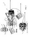
図1は、手術台14上に横たわっている患者12に対して最小侵襲性の診断又は外科的処置を行うために典型的に使用される遠隔操作手術システム10の平面図である。システムは、処置中に外科医18が使用するための外科医コンソール16を含むことができる。1人又はそれ以上のアシスタント20もこの処置に参加することができる。遠隔操作手術システム10は、患者側カート22及び電子機器カート24をさらに含むことができる。患者側カート22によって、外科医18が、外科医コンソール16を介して手術部位を見ながら、少なくとも1つの取り外し可能に結合されたツールアセンブリ26(以下、単に「ツール」と呼ぶ)を患者12の身体の最小侵襲性切開部を介して操縦することができる。手術部位の画像は、立体内視鏡等の内視鏡28によって取得することができ、患者側カート22によって内視鏡28を操縦して向き合わせすることができる。外科医コンソール16を介して外科医18に後で表示するために、電子機器カート24を使用して手術部位の画像を処理することができる。一度に使用される手術用ツール26の数は、一般に、数ある要因の中でも診断又は医療処置、及び手術室内の空間的な制約に依存するだろう。処置中に使用される1つ又は複数のツール26を変更する必要がある場合に、アシスタント20は、患者側カート22からツール26を取り外し、そのツールを手術室のトレイ30にある別のツール26と交換することができる。 FIG. 1 is a plan view of a remote controlled
図2は、外科医コンソール16の斜視図である。外科医コンソール16は、奥行き知覚を可能にするような手術部位の調整された立体視を外科医18に提示するための左眼用ディスプレイ32と右眼用ディスプレイ34とを含む。コンソール16は、1つ又は複数の制御入力36をさらに含み、患者側カート22(図1に示される)に1つ又は複数のツールを操縦させる。入力制御装置36は、関連するツール26(図1に示される)と同じ自由度を提供して、外科医18にテレプレゼンス(すなわち、入力制御装置36がツール26と一体であるという知覚)を提供することができ、それによって外科医は、ツール26を直接的に制御しているという強い感覚を有することになる。この目的のために、位置、力、及び触覚フィードバックセンサ(図示せず)を使用して、ツール26からの位置、力、及び触覚感覚を入力制御装置36を介して外科医の手に戻して伝達させることができる。 FIG. 2 is a perspective view of the
外科医コンソール16は、通常、外科医が処置を直接的に監視し、必要な場合にその場に物理的に存在し、電話や他の通信媒体を介すのではなくアシスタントと直接的に話すことができるように、患者と同じ部屋に配置される。しかしながら、外科医は、異なる部屋、完全に異なる建物、又は遠隔外科的処置(すなわち、滅菌場の外部からの手術)を可能にする患者から離れた他の遠隔位置に位置してもよい。 The
図3は、電子機器カート24の斜視図である。電子機器カート24は、内視鏡28と結合され、取り込んだ画像を処理し、その後に外科医コンソール上で又はローカル及び/又はリモートに位置する別の適切なディスプレイ上で外科医等に表示させるために、プロセッサを含む。例えば、立体内視鏡が使用される場合に、電子機器カート24は、取り込んだ画像を処理して手術部位の調整された立体画像を外科医に提示することができる。そのような調整は、対向する画像同士の間の位置合せを含むことができ、且つ立体内視鏡の立体動作距離を調整することを含むことができる。別の例として、画像処理は、光学収差等の画像取込み装置の結像誤差を補償するために以前に決定されたカメラ較正パラメータの使用を含むことができる。 FIG. 3 is a perspective view of the
図4は、(図1の遠隔操作手術システム10等の)遠隔操作手術システム50を図式的に示す。上述したように、(図1の外科医コンソール16等の)外科医コンソール52は、外科医が最小侵襲性処置中に(図1の患者側カート22等の)患者側カート54を制御するために使用される。患者側カート54は、立体内視鏡等の撮像装置を使用して手術部位の画像を取り込み、取り込んだ画像を(図1の電子機器カート24等の)電子機器カート56に出力することができる。上述したように、電子機器カート56は、その後に表示にする前に取り込んだ画像を様々な方法で処理することができる。例えば、電子機器カート56は、外科医コンソール52を介して外科医に合成画像を表示する前に、取り込んだ画像を仮想制御インターフェイスに重ね合わせる(オーバーレイする)ことができる。患者側カート54は、取り込んだ画像を電子機器カート56の外部で処理するために出力することができる。例えば、患者側カート54は、取り込んだ画像をプロセッサ58に出力することができ、プロセッサ58を使用して取り込んだ画像を処理することができる。画像は、取り込んだ画像を一緒に、順次に、及び/又はこれらの組合せで処理するように一緒に結合され得る電子機器カート56及びプロセッサ58の組合せによって処理することもできる。1つ又は複数の別個のディスプレイ60は、処置部位の画像又は他の関連する画像等の画像のローカル及び/又はリモート表示のために、プロセッサ58及び/又は電子機器カート56を結合することもできる。 FIG. 4 schematically shows a remote controlled surgical system 50 (such as the remote controlled
図5a及び図5bは、それぞれ、患者側カート22及び手術用ツール62を示す。手術用ツール62は、手術用ツール26の一例である。示される患者側カート22は、3つの手術用ツール26と、処置部位の画像を取り込むために使用される立体内視鏡等の撮像装置28とを操縦するために提供される。操縦は、多数の関節(joints)を有する機構によって提供される。撮像装置28及び手術用ツール26は、患者の切開部を介して位置付け及び操縦され、切開部のサイズを最小化するように、運動学的な遠隔中心が切開部に維持される。手術部位の画像は、手術用ツール26が撮像装置28の視野内に位置付けされたときに、手術用ツール26の先端部の画像を含むことができる。 5a and 5b show the patient-
図6は、多くの実施形態による、エンドエフェクタ本体72を器具シャフト74に結合する2自由度の手首(wrist)70の斜視図である。手首70は、支持部材76と、第1のヒンジ点78と、中間部材80と、第2のヒンジ点82と、第3のヒンジ点84とを含む。支持部材76は、図示されるように、器具シャフト74のボア内に位置付けされるように、4つの取付け機構86(例えば、機械式締結具)を介して器具シャフト74に固定して取り付けられる。中間部材80は、中央に配置された第1のヒンジ点78を介して第1の軸線88を中心に回転するように、支持部材76に旋回可能に結合される。エンドエフェクタ本体72は、周辺に配置された第2のヒンジ点82及び周辺に配置された第3のヒンジ点84を介して第2の軸線90を中心に回転するように、中間部材80に旋回可能に結合される。第2のヒンジ点82及び第3のヒンジ点84は、第2の軸線90と同軸であり且つ整列している。第2の軸線90は、第1の軸線88を中心にして中間部材と共に旋回する。 FIG. 6 is a perspective view of a two-degree-of-
第1の軸線88及び第2の軸線90は、所望の運動学特性及び/又は空間特性を有するコンパクトな2自由度の手首を提供するように位置付けすることができる。例えば、第1の軸線88及び第2の軸線90は、同一面上にあり得、それによってボール式関節のような運動学をコンパクトな手首部材に提供する。多くの実施形態では、第1の軸線88及び第2の軸線90は、器具シャフト74の細長い方向に沿って所望の距離だけ分離される。このような分離は、2自由度の手首を介して器具シャフト74に対してエンドエフェクタ本体72を向き合せするために使用される作動システム要素の運動学に手首機構の運動学を近似及び/又は一致させるために使用される。多くの実施形態では、第1の軸線88及び第2の軸線90は、器具シャフト74に対してエンドエフェクタ本体72を向き合せするために使用される作動システム要素の運動学に略一致させる運動学及びコンパクト性の所望の組合せを2自由度の手首に与えるように、器具シャフト74の細長い方向に沿って所望の距離だけ分離される。例えば、第1の軸線88と第2の軸線90との間の4ミリメートル(mm)の離間距離が使用される作動システム要素の運動学に一致する場合に、2自由度の手首は、よりコンパクトな手首を提供するように、より小さい離間距離(例えば、2mm)で構成することができる。多くの実施形態では、このような離間距離の妥協は、使用される作動システム要素の向きの運動学に正確には一致しないことによる重大な有害な動作特性を誘発することなく、使用することができる。第1の軸線88及び第2の軸線90は、所望の空間特性を有するコンパクトな2自由度の手首を提供するように位置付けすることができる。例えば、第1の軸線88及び第2の軸線90は、作動システム要素及び関連する取付け機構に追加の空間を与えるために分離され得る。 The first axis 88 and the second axis 90 can be positioned to provide a compact two-degree-of-freedom wrist with the desired kinematic and / or spatial characteristics. For example, the first axis 88 and the second axis 90 can be on the same plane, thereby providing kinematics such as a ball joint to a compact wrist member. In many embodiments, the first axis 88 and the second axis 90 are separated by a desired distance along the elongated direction of the
支持部材76は、器具シャフト74と第1のヒンジ点78との間に移行可能な継手(transitional
fitting)を提供する。支持部材76は、矩形の主要部分92と、片持ち式の先端部分100とを含む。矩形の主要部分92は、器具シャフトのボアの内径よりも小さい厚さを有し、関節運動及び/又は作動要素(図示せず)の経路指定のための2つの隣接領域のボア開口部を残す。支持部材の主要部分92は、器具シャフトのボア内に経路指定されたエンドエフェクタ制御ケーブルを案内するために使用される2つの内部通路94を含む。内部通路94は、主要部分92の基端部96と主要部分92の先端部98との間に経路指定され、且つ器具シャフト74の細長い方向とほぼ整列される。以下にさらに説明するように、多くの実施形態では、内部通路94は、中間部材のケーブル案内面と協働して、一定の制御ケーブル経路長を維持することによって、第1及び第2の軸線周りの旋回中に制御ケーブルの張力を変更しないように構成される。片持ち式の先端部分100は、第1のヒンジ点78の単一の旋回シャフトを受容する取付けラグを有する。単一の旋回シャフトの使用は単なる例示であり、第1のヒンジ点78の代わりに他の旋回(pivot)関節要素を使用してもよく、例えば、同じ軸線上に整列された2つの旋回ピンを使用してもよい。支持部材76は、器具シャフト74及びエンドエフェクタ本体72に対して第1のヒンジ点78(従って、第1の軸線88)を所望の位置に配置し、例えば、エンドエフェクタ本体72と器具シャフト74との間に器具シャフト74に対するエンドエフェクタ本体72の所望範囲の再向き合わせのためのクリアランスを提供するように構成される。The
fitting) is provided. The
中間部材80は、第1のヒンジ点78と第2のヒンジ点82と第3のヒンジ点84との間に移行可能な継手を提供する。中間部材80は、器具シャフトのボアの内径より小さい厚さ(例えば、主要部分92の厚さと同様)を有する矩形の細長い主要部分を含み、器具シャフトのボアは、関節運動及び/又は作動要素(図示せず)の経路指定(引回し)のために開いている2つの隣接領域を残す。中間部材80は、支持部材の先端部分100の取付けラグを受容するように構成された中央スロット102を含む。中央スロット102は、第1の軸線88を中心とする中間部材80の回転範囲に亘って先端部分100の取付けラグを収容するように構成される。中央スロット102はまた、支持部材の内部通路94を通って引き回されるエンドエフェクタ制御ケーブル(図示せず)を収容するように構成してもよい。中央スロット102はまた、エンドエフェクタ制御ケーブルを案内するように構成された面を含んでもよい。さらに以下で説明するように、多くの実施形態では、中央スロットケーブル案内面は、略一定の制御ケーブル経路長を維持することによって、第1及び第2の軸線周りの旋回中に制御ケーブルの張力を変更しないように構成される。多くの実施形態では、中央スロットケーブル案内面は、内部通路94と協働して、第1及び第2の軸線周りの旋回中に一定の制御ケーブル経路長を維持する。中央スロット102はまた、第1のヒンジ点78の単一の旋回シャフトを受容する反対側の取付けフランジを提供する。第2のヒンジ点82は、中間部材80の第1の端部から片持ち式に保持された旋回シャフトを含む。第3のヒンジ点84は、中間部材80の反対側の第2の端部から片持ち式に保持された旋回シャフトを含む。片持ち式の旋回シャフトの使用は単なる例示であり、他の適切な旋回式関節を使用してもよい。多くの実施形態では、第2及び第3のヒンジ点82,84の位置及び向き(従って、第2の軸線90の位置及び向き)は、第1の軸線88に対する第2の軸線90の所望の位置及び向きを提供するように選択される。例えば、多くの実施形態では、第1及び第2の軸線は非同一面上にある。多くの実施形態では、第1及び第2の軸線は同一面上にある。多くの実施形態では、第1の軸線88に対する第2の軸線90の位置及び/又は向きは、器具シャフト74に対するエンドエフェクタ本体72の動きの所望の運動学を提供するように選択される。 The
図7は、図6の2自由度の手首70の斜視図であり、多くの実施形態による、中間部材80と支持部材76との間の第1の軸線88周りの回転自由度と、エンドエフェクタ本体(図示せず)と中間部材80との間の第2の軸線90周りの回転自由度とを示す。支持部材76は、器具シャフト74の先端部から先端方向の所望の位置に第1のヒンジ点78を位置付けするように器具シャフト74に取り付けられ、例えば、エンドエフェクタ本体と器具シャフトとの間にクリアランスを提供し、エンドエフェクタ本体の動きのための空間を提供する。中間部材の中央スロット102は、エンドエフェクタ制御ケーブル(図示せず)の引回しを調整するために、エンドエフェクタ本体に隣接して中間部材80の側面に開口している。図7の視野方向から、支持部材76の一方の内部通路94が見え、他方の内部通路94は隠れて見えない。多くの実施形態では、1つの制御ケーブルが2つの内部通路94のそれぞれを通って引き回される。これら2つの制御ケーブルのそれぞれは、第1の軸線88の各側に1つずつ、中間部材の中心スロット102を通ってさらに引き回される。 FIG. 7 is a perspective view of the
図8は、多くの実施形態による、2自由度の手首70を有するツールアセンブリ104の簡略化した概略図である。ツールアセンブリ104は、基端側作動アセンブリ106と、メインシャフト108と、エンドエフェクタ110の関節式エンドエフェクタベースと、2自由度の手首70とを含む。多くの実施形態では、基端側作動アセンブリ106は、メインシャフト108に対してエンドエフェクタベースを2次元で選択的に再向き合わせさせるようにエンドエフェクタベースと動作可能に結合され、且つエンドエフェクタベースに対して1つ又は複数のエンドエフェクタ機構を関節運動させるようにエンドエフェクタ110と動作可能に結合される。作動アセンブリ106をエンドエフェクタ110と結合するために、例えば制御ケーブル、ケーブル/ハイポチューブの組合せ、駆動シャフト、プルロッド、及びプッシュロッド等の様々な作動要素を使用することができる。多くの実施形態では、作動要素は、作動アセンブリ106とエンドエフェクタ110との間でメインシャフト108のボアを通して引き回される。このような接続の詳細は、以前に援用した米国特許出願公開第2014/0183244号で確認することができる。 FIG. 8 is a simplified schematic of a
ツールアセンブリ104は、様々な用途、例えば、基端側作動機構106で使用される手動及び/又は自動作動のハンドヘルド装置の使用のために構成することができる。このように、ツールアセンブリ104は、最小侵襲性ロボット手術以外の他の用途、例えば非ロボットによる最小侵襲性手術、非最小侵襲性ロボット手術、非ロボットによる非最小侵襲性手術だけでなく、2自由度の手首の使用が有益となる他の用途を含むことができる。手首70は、以前に援用した米国特許出願公開第2014/0183244号に開示された装置等の、手術用ステープル装置を含むがこれに限定されない、様々なエンドエフェクタに結合することができる。 The
ツールアセンブリ104は、制御システム111に電子的に結合され、制御システム111は、ツールアセンブリを制御するための少なくとも1つのプロセッサと、少なくとも1つのプロセッサによって本明細書に記載の方法動作を行うように実行可能な非一時的な命令を記憶するメモリとを含む。制御システム111は、ツールアセンブリの任意の部分等の任意の適切な位置に配置することができ、又は制御システム111は、患者側カート22/54又は外科医コンソール16のサブシステムの一部であり得る。一般に、制御システム111は、本明細書に開示される方法を実施するための命令を実行するように構成される。 The
図9は、ツールアセンブリ104の簡略図である。エンドエフェクタ110は、ヒンジ116によって下顎部分114に接続された上顎部分112を含む。上顎112は、ヒンジ116において上顎112を回転させることにより、下顎部分114に対して開閉することができる。この実施形態では、下顎部分114がヒンジを担持しているので、下顎部分114はヒンジ116で作動することができない。しかしながら、他の実施形態では、両方の顎部分がヒンジ116で作動することができる。下部顎部分114は、ヒンジ116で上顎部分112を作動させるための1つ又は複数の機構を含む。このような機構の詳細は、以前に援用した米国特許出願公開第2014/0183244号で確認することができる。ヒンジ116は、手首70から空間的に分離されている。このように、下顎部分114は、上顎部分112を担持しながら、手首70においてピッチ及びヨー運動をすることができる。 FIG. 9 is a simplified view of the
図10は、下側顎部分114に対して上側顎部分112を作動させるためのツールアセンブリ104の第1の動作モードを示す。動作中、軸線A−A上の上顎112は軸線B−B上の下顎114に向けて相対的に移動する。簡略化のために、メインシャフトの軸線C−Cは軸線B−Bと同一線上にあるように示されているが、これは必須ではない。手首70におけるシャフト108の回転及び下顎114の移動等のツールアセンブリ104の他の動作が、この時間中に起こり得るが、一般に、軸線B−Bは、エフェクタ110のより重要な手術動作のために空間内に静止状態で保持され得る。 FIG. 10 shows a first mode of operation of the
図11は、下顎部分114に対して上顎部分112を作動させるためのツールアセンブリ104の第2の動作モードを示す。場合によっては、カメラに対する外科医の視界は、上顎部分112が下顎部分114に近づくようにヒンジ116で作動される間に、上顎部分112の軸線A−Aを患者に対して比較的静止したままにするのが好ましい。従って、第2の動作モードでは、下顎部分114は、上顎部分112が下顎部分114に向けて作動され、空間内での軸線A−Aの静止位置を提供するときに、(例えば、手首70の関節運動を介して)再向き合わせ及び/又は再位置付けされ得る。下顎部分114の作動は、手首70及び/又は器具シャフト108の関節運動を介して達成され、上顎部分112は、下顎部分114が上顎部分112に対して再向き合わせされる間に、空間に静止したままである。 FIG. 11 shows a second mode of operation of the
図示される実施形態では、手首70とヒンジ116との間の空間的な分離により、空間内での上顎部分112及び軸線A−Aの位置は、常に正確に維持されるとは限らないが、外科医の目的のために実質的に十分維持される。言い換えれば、空間内の上顎部分112の位置は、幾分変化する可能性があるが、下顎部分114が空間内を移動する量に比べて殆ど変化しない。これは、患者側カート22の運動学的制限、又はいくつかの場合に、患者側カート22及び/又はツールアセンブリ104の態様(aspect)との潜在的な衝突のために所望の操縦が妨げられ物理的障壁(例えば、腹壁)に起因し得る。しかしながら、いくつかの場合には、空間内のシャフト108の動きは、空間内の軸線A−A及びヒンジ116の正確な位置を維持するのを助けるように顎部分の作動が起こる間に、手首70の位置を動かすように行われる。 In the illustrated embodiment, the spatial separation between the
図5aに示されるように、患者側カート22のアームの1つ又は複数の可動態様を、上顎部分112及び軸線A−Aの正確な位置を周囲空間内に維持するように操縦することができる。場合によっては、これは、ツールアセンブリ104を保持するアームの運動の最大7軸までの協調運動を必要とする可能性がある。このようなアーム及び運動軸線の例は、米国特許第7,594,912号、及び特許出願公開第2013/0325032号に開示されており、これらの文献は、参照により本明細書に組み込まれる。上述した手首70とヒンジ116との特別な分離のために、図11に示されるように、手首70は、患者側カート22の制御と、ツールアセンブリ104を保持するアームのいくつかの可動態様の操縦とによって下向きに移動され、上顎部分112の位置を正確に維持することができる。 As shown in FIG. 5a, one or more movable modes of the arm of the patient-
図11に示される第2の動作モードは、上顎部分112が空間内に略静止状態で保持されるように、下顎部分114に対する上顎部分112の関節運動が、手首70の同時関節運動を伴う点で図10に示される第1の動作モードとは異なる。対照的に、図10に示される第1の動作モードでは、下顎部分114に対する上顎部分112の関節運動は、上顎部分112が空間内での位置を変えるように、手首70の関節運動とは独立して生じる。第2の動作モードは、任意の適切な手術用ツールの動作を制御するために使用することができる。さらに、ツールの任意の適切な態様は、下顎部分114に対する上顎部分112の作動中に、静止状態に保持されるように選択することができる。 The second mode of motion shown in FIG. 11 is that the joint movement of the
第2の動作モードは、いくつかの異なる方法で規定(enacted)することができ、例えば、第2の動作モードは、コンソール16で提供されるオプションとすることができる。他の実施形態では、第2の動作モードは、指定された処置、エンドエフェクタ110上に配置された物理的な選択スイッチ、又はエンドエフェクタ110に組み込まれるステープラ・カートリッジ(又は他のツールインサート)上に位置する電子識別子の結果としてデフォルトにされる(カートリッジは、ユーザに識別させるために、色に基づいて色分けすることができる)。他の実施形態では、第2の動作モードは、手首70が特定の位置又は角度に関節運動されたときに規定される。他の実施形態では、第2の動作モードの角度限界は、ユーザによって調整され得る。さらに、上顎部分112は、これらの例では、静止状態に保持されるエンドエフェクタの基準態様(reference aspect)として使用されるが、代わりに、ツールアセンブリ104の任意の適切な態様を使用してもよい。例えば、上顎部分112と下顎部分114との間の開いた角度の間にある軸線等の仮想基準軸線を選択して静止状態に保持することができる。仮想基準軸線は、コンソール16上の適切な表示要素によって表すことができる。他の例として、ツールの任意の適切な部分を選択して静止状態に保持することができる。ツールアセンブリ104の動作前又は動作中にユーザは、ツールアセンブリ104の関節運動中に静止状態に保持されるような基準軸線又は対象物を随意に選択することができる。エンドエフェクタの適切な選択可能な基準態様は、リアルタイムで選択可能なオプションのリストとしてコンソール16上に視覚的に提供することができる。 The second mode of operation can be enacted in a number of different ways, for example, the second mode of operation can be an option provided by the
図12は、下顎部分114が手首70に対して機械的限界にある例を示している。ここで、軸線B−Bと軸線C−Cとの間の角度αは、手首70と下顎114との機械的限界のため最大の角度である。この位置は、上顎部分112がヒンジ116で自由に旋回するので、図10に示される第1のモード動作を妨げない。この位置はまた、下顎部分114が必要とする相対的な動きが手首70によって妨げられず、角度αを増大させる必要がなく、減少させる(ここでは限定されない)必要があるだけなので、図11に示される第2の動作モードを妨げない。 FIG. 12 shows an example in which the
図13は、下顎部分114が手首70に対して機械的限界にある他の例を示す。ここで、軸線B−Bと軸線C−Cとの間の角度α1は、手首70と下顎114との機械的限界のため最大の角度である。この位置は、上顎部分112がヒンジ116で自由に旋回するので、図10に示される第1のモード動作を妨げない。しかしながら、この位置は、下顎部分114が必要とする相対的な動きが手首70によって妨げられ、角度α1をさらに増大させることができないので、図11に示される第2の動作モードを妨げる。FIG. 13 shows another example in which the
第2の動作モードが望ましいこのような状況では、いくつかの代替モードが発生する可能性がある。いくつかの実施形態では、第2の動作モードでは、下顎部分114のピッチ及びヨー運動は、電子的に(α1−x)となるように制限され、それによって角度α1を必要に応じて所定量のxまで増大させることができ、ここで、xは、第2の動作モードを提供するための最小角度である。他の実施形態では、下顎部分114のピッチ及び/ヨー運動は制限されず、コンソール16は、第2の動作モードが利用可能ではないという指標を外科医に提供するように構成される。他の実施形態では、下顎部分114のピッチ及びヨー運動は制限されず、エンドエフェクタ110の動きは、そのような状況では第1の動作モードに自動的に切り替わる。いくつかの実施形態では、角度α1はハードストップではないが、第2の動作モードの完全な動作を提供するための適切な位置ではハードストップとなり得る。そのような場合には、第2の動作モードを、角度α1によって提供される最大量まで規定することができ、次に、第1の動作モードは、顎部分を閉じて終了するように規定することができる。こうして、動作のある部分は、上顎部分112によって行われ、動作のある部分は、下顎部分114によって行われ得る。いくつかの実施形態では、動作の極一部が第2の動作モードを介して達成される場合に、第1の動作モードへの切り替えを自動的に行うことができる。In such situations where a second mode of operation is desirable, some alternative modes may occur. In some embodiments, in the second mode of motion, the pitch and yaw movements of the
図14は、エンドエフェクタ(エンドエフェクタ110等)を有するツールアセンブリ104等のツールを動作させるための方法120を示す。この方法120は、本明細書に記載の手術システム等の任意の適切な手術システムを使用して実施することができる。多くの実施形態では、この方法120は、制御システム111のプロセッサ等の少なくとも1つのプロセッサを使用して行われる。 FIG. 14 shows a
方法120は、制御装置が、エンドエフェクタを閉じる又は開けるためのコマンドを受信するステップ(動作122)を含む。任意の適切なエンドエフェクタを使用してもよい。例えば、エンドエフェクタは、ヒンジによって第2の顎部材に接合された第1の顎部材を含むことができる。エンドエフェクタは、器具シャフトに対してエンドエフェクタを関節運動させるように再構成可能な手首によって器具シャフトに結合され、それによって患者に対してエンドエフェクタを再向き合わせ及び/又は再位置付けすることができる。いくつかの実施形態では、器具シャフトはまた、エンドエフェクタを空間内に再向き合せ及び/又は再位置付けするように関節運動され得る。
方法120は、制御装置が、エンドエフェクタの基準態様を指定する入力を受信するステップ(動作124)を含むことができる。本明細書に記載の基準態様等の任意の適切な物理的態様又は仮想態様を含む、エンドエフェクタの任意の適切な基準態様は、ユーザ及び制御装置に設けられた対応する入力によって指定することができる。あるいはまた、エンドエフェクタのデフォルトの基準態様を使用してもよい。エンドエフェクタの基準態様は、エンドエフェクタの現在の向き及び/又は位置等の、任意の適切な既知の状態情報に基づいて制御装置によって選択することもできる。例えば、空間におけるエンドエフェクタの現在の向き及び/又は位置を使用して、患者の隣接する組織に最も近くにある基準態様を選択することができ、エンドエフェクタを閉じる又は開ける間にエンドエフェクタと患者の隣接する組織との間の望ましくない接触を防止することができる。 The
方法120は、コマンドに応答して、制御装置が、同時に、(a)第2の顎部材に対して第1の顎部材を移動させ、(b)器具シャフトに対してエンドエフェクタを向き合せするように手首を作動させるように、エンドエフェクタの関節運動を制御し、それによってエンドエフェクタの基準態様の位置及び/又は向きが空間内で実質的に維持される(動作126)。エンドエフェクタの任意の適切な同時関節運動を使用することができる。例えば、手首は、第1の顎部材が第2の顎部材に対して再向き合わせされている間に、エンドエフェクタの基準態様を略静止状態に保持するように、器具シャフトに対してエンドエフェクタを関節運動させるように再構成することができる。さらに、器具シャフトは、単独で、又は手首の関節運動と組み合わせて関節運動され、第1の顎部材が第2の顎部材に対して移動している間に、エンドエフェクタの基準態様が略静止状態に保持されるように、エンドエフェクタを空間内で向き合わせすることができる。 In
方法120は、制御装置が、エンドエフェクタを閉じる又は開ける間にエンドエフェクタの基準態様を静止状態に保持するためのエンドエフェクタの動きが運動限界を超えるかどうかを判定するステップ(動作128)を含むことができる。例えば、エンドエフェクタを閉じる又は開ける間にエンドエフェクタの基準態様を静止状態に保持するためにエンドエフェクタの動きを生成するために使用され得る手首及び/又は器具シャフトの再構成は、手首及び/又は器具シャフトの残りの利用可能な再構成と比較される。手首及び/又は器具シャフトの現在の構成から利用可能な再構成が、エンドエフェクタを閉じる又は開ける間にエンドエフェクタの基準態様を静止状態に保持するのに十分であると制御装置が判断した場合に、制御装置は、エンドエフェクタを閉じる又は開ける間にエンドエフェクタの基準態様を静止状態に保持するように、エンドエフェクタの関節運動を制御するステップに進むことができる。手首及び/又は器具シャフトの現在の構成から利用可能な再構成が、エンドエフェクタを閉じる又は開ける間にエンドエフェクタの基準態様を静止状態に保持するのには不十分であると制御装置が判断した場合に、制御装置は、エンドエフェクタを閉じる又は開ける対応する部分の間に、エンドエフェクタの基準態様を静止状態に保持するように、エンドエフェクタの関節運動を制御するステップに進むことができる。 The
さらに、制御装置は、エンドエフェクタを閉じる又は開ける間にエンドエフェクタの基準態様を静止状態に保持するためにエンドエフェクタを同時に関節運動させることなく、エンドエフェクタを閉じる又は開けることができるように構成し得る。例えば、方法120は、制御装置が、エンドエフェクタを閉じる又は開けるための第2のコマンドを受信するステップを含むことができる。第2のコマンドを受信することに応答して、制御装置は、エンドエフェクタの基準態様の位置及び/又は向きが空間内で実質的に維持されるようにエンドエフェクタを(例えば、手首及び/又は器具シャフトの関節を介して)同時に関節運動させることなく、第2の顎部材に対して第1の顎部材を再向き合わせするようにエンドエフェクタの関節運動を制御することができる(動作130)。 In addition, the controller is configured to allow the end effector to be closed or opened without simultaneous joint movement of the end effector to keep the reference mode of the end effector stationary while the end effector is closed or opened. obtain. For example,
他の変形形態が、本発明の精神の範囲内にある。記載された実施形態の様々な態様、実施形態、実装形態又は特徴は、別々に又は任意の組合せで使用することができる。手術用ツールの動作に関連する説明した実施形態の様々な態様は、ソフトウェア、ハードウェア、又はハードウェアとソフトウェアとの組合せによって実施することができる。こうして、本発明は、様々な修正及び代替構成が可能であるが、その図示された特定の実施形態が図面に示されており、上で詳細に説明している。しかしながら、開示された特定の形態に本発明を限定する意図はないが、反対に、本発明は、添付の特許請求の範囲に規定されるような、本発明の精神及び範囲内に入る全ての修正、代替構成、及び均等物を網羅することを意図するものである。 Other variants are within the spirit of the invention. The various embodiments, embodiments, implementations or features of the described embodiments can be used separately or in any combination. Various aspects of the described embodiments relating to the operation of surgical tools can be performed by software, hardware, or a combination of hardware and software. Thus, the present invention allows for various modifications and alternative configurations, the specific embodiments illustrated thereof are shown in the drawings and are described in detail above. However, while we do not intend to limit the invention to the particular embodiments disclosed, the invention, on the contrary, is all within the spirit and scope of the invention as set forth in the appended claims. It is intended to cover modifications, alternative configurations, and equivalents.
本発明を説明する文脈(特に以下の特許請求の範囲の文脈)における「1つの(a, an)」及び「その(the)」及び同様の指示語の使用は、本明細書に他に指示がない限り或いは本明細書の文脈に明らかに矛盾しない限り、単数及び複数の両方を網羅するように解釈される。用語「備える、有する、含む(comprising)」、「有する、含む(having)」、「含む、有する(including)」、「含む(containing)」は、特に断りのない限り、オープンエンドの用語に解釈される(すなわち、「含む、有する(including)」を意味するが、これらに限定されるものではない)。用語「接続される」は、間に何か介在するものがあっても、何かに部分的に又は完全に含まれる、何かに取り付けられる、又は何かと一緒に接合されるように解釈される。本明細書での値の範囲の記載は、本明細書に他に指示がない限り、この範囲に含まれる各別個の値を個別に参照する簡便な方法の役割を果たすことが単に意図されており、各別個の値は、本明細書に個別に記載されるように、明細に組み込まれる。本明細書で説明する全ての方法は、本明細書に他に指示がない限り或いは本明細書の文脈に明らかに矛盾しない限り、任意の適切な順序で行うことができる。本明細書に記載された、いくつかの及び全ての例、又は例示的な言葉(例えば、「等」)の使用は、単に本発明の実施形態をより良く説明することを意図しており、他に注記がない限り、本発明の範囲を限定するものではない。明細書中の言語は、特許請求の範囲に記載していない要素を、本発明を実施するのに不可欠な要素として示すように解釈すべきない。 The use of "one (a, an)" and "the" and similar directives in the context of describing the present invention (particularly in the context of the scope of the following patent claims) is otherwise indicated herein. Unless otherwise specified or clearly inconsistent with the context of the present specification, it is to be construed as covering both singular and plural. The terms "comprising," "having," "including, including," and "containing" are to be interpreted as open-ended terms unless otherwise noted. (Ie, but is not limited to, including, but is limited to). The term "connected" is interpreted to be partially or completely contained in something, attached to something, or joined together with something, even if there is something in between. .. The description of a range of values herein is merely intended to serve as a convenient way to individually reference each distinct value contained within this range, unless otherwise indicated herein. And each separate value is incorporated into the specification as described individually herein. All methods described herein can be performed in any suitable order, unless otherwise indicated herein or which is clearly inconsistent with the context of the present specification. The use of some and all examples, or exemplary terms (eg, "etc.") described herein is merely intended to better illustrate embodiments of the invention. Unless otherwise noted, the scope of the invention is not limited. The language in the specification should not be construed to indicate elements not mentioned in the claims as essential elements for practicing the present invention.
本発明を実施するために本発明者らに知られている最良の形態を含む、本発明の好ましい実施形態を本明細書に記載する。これらの好ましい実施形態の変形形態は、前述の詳細な説明を読むことにより当業者には明らかになるであろう。本発明者らは、当業者がこのような変形を適切に使用することを予期しており、本発明者らは本発明が本明細書に具体的に記載されたものとは別の方法で実施されることを意図する。従って、本発明は、適用法によって認められるように、添付の特許請求の範囲に記載された主題の全ての改変及び均等物を含む。さらに、本明細書中に他に指示されない限り或いは文脈によって明らかに矛盾しない限り、それらの全ての可能な変形における上述した要素の任意の組合せが本発明に包含される。
Preferred embodiments of the invention are described herein, including the best known embodiments of the invention for carrying out the invention. Modifications of these preferred embodiments will be apparent to those of skill in the art by reading the above detailed description. We anticipate that those skilled in the art will use such modifications appropriately, and we will in a manner different from that of the invention specifically described herein. Intended to be implemented. Accordingly, the invention includes all modifications and equivalents of the subject matter described in the appended claims, as permitted by applicable law. Moreover, any combination of the above-mentioned elements in all possible variations thereof is included in the present invention unless otherwise indicated herein or is not clearly inconsistent in context.
Claims (23)
Translated fromJapanese制御装置が、前記エンドエフェクタの第2の顎部材に対して前記エンドエフェクタの第1の顎部材を再向き合わせするためのコマンドを受信するステップであって、前記第1の顎部材は、ヒンジによって前記第2の顎部材に接合され、前記第2の顎部材は、手首によって器具シャフトに結合され、前記手首は、前記器具シャフトに対して前記第2の顎部材を再向き合わせするように再構成される、受信するステップと、
前記第2の顎部材に対して前記第1の顎部材を再向き合わせするための前記コマンドに応答して、前記制御装置が、同時に、前記第2の顎部材に対して前記第1の顎部材を再向き合わせし、且つ前記器具シャフトに対して前記第2の顎部材を再向き合わせするべく前記手首を再構成させることを制御するステップと、を含む、
方法。It is a method of controlling the movement of the end effector, and the method is
The control device receives a command forreorienting the first jaw memberof the end effector with respect to the second jaw member of the end effector, wherein the first jaw member is a hinge. is joined to said second jaw member by said second jaw member is coupled to the instrument shaft by the wrist, the wrist istorealign the orientation of saidsecond jaw member relative to the instrument shaft Rureconstructed, receiving,
In response to saidcommand to realign the orientation of the first jaw member to the second jaw member, wherein the controller, at the same time,the first jaw relative tothe second jaw member was combined member re orientation, comprising the steps of controllingthe Rukoto reconstituted the wrist in order to realign the orientation of saidsecond jaw member relative且previous SL instrument shaft, and
Method.
前記第2の顎部材は、前記ヒンジで旋回しないように構成される、請求項1に記載の方法。The first jaw member to pivot with the hinge is configured so as to come close tothe second jaw member,
The method according to claim 1, wherein the second jaw member is configured so as not to rotate at the hinge.
前記制御装置が、前記第2の顎部材に対して前記第1の顎部材を再向き合わせするための第2のコマンドの受信に応答して、第2の顎部材を静止状態に保持している間に、同時に、前記第2の顎部材に対して前記第1の顎部材を再向き合わせし、且つ前記器具シャフトに対して前記第2の顎部材を再向き合わせするべく前記手首を再構成させることを制御するステップと、をさらに含む、請求項1に記載の方法。A step in which the control device receives a second command forreorienting the first jaw member with respect to the second jaw member.
The control device holds the second jaw member stationary in response to receiving a second commandto reorient the first jaw member to the second jaw member.At the same time, the wrist is re-oriented to re-orient the first jaw member to the second jaw member and re-orient the second jaw member to the instrument shaft. The method of claim 1, further comprising a stepof controlling the configuration.
同時に、前記第2の顎部材に対して前記第1の顎部材を再向き合わせし、且つ前記器具シャフトに対して前記第2の顎部材を再向き合わせするべく前記手首を再構成させる間に、前記エンドエフェクタの前記基準態様の空間内の位置及び空間内の向きの少なくとも1つを維持するステップと、をさらに含む、請求項1に記載の方法。The step of receiving the input that specifies the reference mode of the end effector, and the step that the control device receives.
At the same time,while the secondand pair jaw membersto realign the orientationofthe first jawmember, causing and reconstituted the wrist in order to realign the orientation of said second jaw member relative to the instrument shaft infurther comprising the steps of: maintaining at least one of the orientation of the position and space of the space of the reference embodiment of the end effector, the method according to claim 1.
エンドエフェクタ、手首、及び該手首に結合された先端部を有する器具シャフトを含むロボットアームであって、前記エンドエフェクタは、第1の顎部材、第2の顎部材、及び前記第1の顎部材を前記第2の顎部材に旋回可能に結合するヒンジを含み、前記エンドエフェクタは前記手首に結合され、該手首は、前記器具シャフトに対して前記第2の顎部材を再向き合わせするように再構成可能である、ロボットアームと、
前記ロボットアームを動作させるための制御装置であって、該制御装置は、少なくとも1つのプロセッサと、該少なくとも1つのプロセッサによって実行可能な命令を記憶するメモリ装置とを含み、前記命令は、前記少なくとも1つのプロセッサに、
前記第2の顎部材に対する前記第1の顎部材の再向き合わせを実現するためのコマンドを受信させ、
前記第2の顎部材に対する前記第1の顎部材の再向き合わせを実現するための前記コマンドの受信に応答して、同時に、前記第2の顎部材に対して前記第1の顎部材を再向き合わせさせ、且つ前記器具シャフトに対して前記第2の顎部材を再向き合わせするべく前記手首を再構成させることを制御させる、制御装置と、有する、
システム。It is a robotic surgery system, and the system is
The end effector, the wrist, and a robot arm comprising an instrument shaft having a distal end coupled to該手neck, wherein the end effector, the first jaw member, a second jaw member, andsaid first jaw member the include hinge pivotally coupled tothe second jaw member, wherein the end effector is coupled to the wrist,該手neck, so as to realign the orientation of saidsecond jaw member relative to the instrument shaft Reconfigurable robot arm and
A control device for operating the robot arm, wherein the control device includes at least one processor and a memory device that stores instructions that can be executed by the at least one processor, and the instructions are at least said. In one processor
To receive commands for implementing the re-orientation alignment ofthe first jaw member relative tothe second jaw member,
In response to receiving the command for realizing re orientation alignment ofthe first jaw member relative tothe second jaw member, at the same time,the first jaw member tothe second jaw memberre isorientation aligned, then reconstructing the wrist in order to realign the orientation of saidsecond jaw member relative且previous SL instrument shaft is controlledRukoto, a control device has,
system.
前記第2の顎部材は、前記ヒンジで旋回するように構成されていない、請求項12に記載のシステム。The first jaw member to pivot with the hinge is configured so as to come close tothe second jaw member,
12. The system of claim 12, wherein the second jaw member is not configured to swivel at the hinge.
前記第2の顎部材に対する前記第1の顎部材の第2の再向き合わせを実現するための第2のコマンドを受信させ、
前記第2の顎部材に対する前記第1の顎部材の第2の再向き合わせを実現するための第2のコマンドの受信に応答して、第2の顎部材を静止状態に保持している間に、同時に、前記第2の顎部材に対して前記第1の顎部材を再向き合わせし、且つ前記器具シャフトに対して前記第2の顎部材を再向き合わせするべく前記手首を再構成することを制御させる、請求項12に記載のシステム。The memory device stores instructions that can be executed by the at least one processor, and the instructions are transmitted to the at least one processor.
A second command forrealizing the second reorientation of the first jaw member with respect to the second jaw member is received.
While holding the second jaw member stationary in response to receiving a second commandto achieve a second reorientation of the first jaw member with respect to the second jaw member.At the same time, the wrist is reconstructed so that the first jaw member is reoriented with respect to the second jaw member and the second jaw member is reoriented with respect to the instrument shaft. thereby controllingthe system of claim 12.
同時に、前記第2の顎部材に対して前記第1の顎部材を再向き合わせし、且つ前記器具シャフトに対して前記第2の顎部材を再向き合わせするべく前記手首を再構成する間に、前記エンドエフェクタの前記基準態様の空間内の位置及び空間内の向きの少なくとも1つが、維持される、請求項12に記載のシステム。The memory device stores instructions that can be executed by the at least one processor, which causes the at least one processor to receive an input that specifies a reference embodiment of the end effector.
At the same time, while the wrist is reconstructed so that the first jaw member is reoriented with respect to the second jaw member and the second jaw member is reoriented with respect to the instrument shaft. , wherein at least one of the orientation of the position and space of the space of the reference embodiment of the endeffector, ismaintained, the system according to claim 12.
Applications Claiming Priority (3)
| Application Number | Priority Date | Filing Date | Title |
|---|---|---|---|
| US201562254154P | 2015-11-11 | 2015-11-11 | |
| US62/254,154 | 2015-11-11 | ||
| PCT/US2016/060679WO2017083201A1 (en) | 2015-11-11 | 2016-11-04 | Reconfigurable end effector architecture |
Publications (2)
| Publication Number | Publication Date |
|---|---|
| JP2018538036A JP2018538036A (en) | 2018-12-27 |
| JP6981977B2true JP6981977B2 (en) | 2021-12-17 |
Family
ID=58696089
Family Applications (1)
| Application Number | Title | Priority Date | Filing Date |
|---|---|---|---|
| JP2018524280AActiveJP6981977B2 (en) | 2015-11-11 | 2016-11-04 | Reconfigurable end effector architecture |
Country Status (6)
| Country | Link |
|---|---|
| US (1) | US10799306B2 (en) |
| EP (1) | EP3373838B1 (en) |
| JP (1) | JP6981977B2 (en) |
| KR (1) | KR102597849B1 (en) |
| CN (1) | CN108135665B (en) |
| WO (1) | WO2017083201A1 (en) |
Families Citing this family (375)
| Publication number | Priority date | Publication date | Assignee | Title |
|---|---|---|---|---|
| US20070084897A1 (en) | 2003-05-20 | 2007-04-19 | Shelton Frederick E Iv | Articulating surgical stapling instrument incorporating a two-piece e-beam firing mechanism |
| US9060770B2 (en) | 2003-05-20 | 2015-06-23 | Ethicon Endo-Surgery, Inc. | Robotically-driven surgical instrument with E-beam driver |
| US9072535B2 (en) | 2011-05-27 | 2015-07-07 | Ethicon Endo-Surgery, Inc. | Surgical stapling instruments with rotatable staple deployment arrangements |
| US11998198B2 (en) | 2004-07-28 | 2024-06-04 | Cilag Gmbh International | Surgical stapling instrument incorporating a two-piece E-beam firing mechanism |
| US11890012B2 (en) | 2004-07-28 | 2024-02-06 | Cilag Gmbh International | Staple cartridge comprising cartridge body and attached support |
| US8215531B2 (en) | 2004-07-28 | 2012-07-10 | Ethicon Endo-Surgery, Inc. | Surgical stapling instrument having a medical substance dispenser |
| US11484312B2 (en) | 2005-08-31 | 2022-11-01 | Cilag Gmbh International | Staple cartridge comprising a staple driver arrangement |
| US9237891B2 (en) | 2005-08-31 | 2016-01-19 | Ethicon Endo-Surgery, Inc. | Robotically-controlled surgical stapling devices that produce formed staples having different lengths |
| US7934630B2 (en) | 2005-08-31 | 2011-05-03 | Ethicon Endo-Surgery, Inc. | Staple cartridges for forming staples having differing formed staple heights |
| US11246590B2 (en) | 2005-08-31 | 2022-02-15 | Cilag Gmbh International | Staple cartridge including staple drivers having different unfired heights |
| US10159482B2 (en) | 2005-08-31 | 2018-12-25 | Ethicon Llc | Fastener cartridge assembly comprising a fixed anvil and different staple heights |
| US7669746B2 (en) | 2005-08-31 | 2010-03-02 | Ethicon Endo-Surgery, Inc. | Staple cartridges for forming staples having differing formed staple heights |
| US20070106317A1 (en) | 2005-11-09 | 2007-05-10 | Shelton Frederick E Iv | Hydraulically and electrically actuated articulation joints for surgical instruments |
| US11224427B2 (en) | 2006-01-31 | 2022-01-18 | Cilag Gmbh International | Surgical stapling system including a console and retraction assembly |
| US20120292367A1 (en) | 2006-01-31 | 2012-11-22 | Ethicon Endo-Surgery, Inc. | Robotically-controlled end effector |
| US20110024477A1 (en) | 2009-02-06 | 2011-02-03 | Hall Steven G | Driven Surgical Stapler Improvements |
| US20110295295A1 (en) | 2006-01-31 | 2011-12-01 | Ethicon Endo-Surgery, Inc. | Robotically-controlled surgical instrument having recording capabilities |
| US7753904B2 (en) | 2006-01-31 | 2010-07-13 | Ethicon Endo-Surgery, Inc. | Endoscopic surgical instrument with a handle that can articulate with respect to the shaft |
| US8708213B2 (en) | 2006-01-31 | 2014-04-29 | Ethicon Endo-Surgery, Inc. | Surgical instrument having a feedback system |
| US7845537B2 (en) | 2006-01-31 | 2010-12-07 | Ethicon Endo-Surgery, Inc. | Surgical instrument having recording capabilities |
| US8820603B2 (en) | 2006-01-31 | 2014-09-02 | Ethicon Endo-Surgery, Inc. | Accessing data stored in a memory of a surgical instrument |
| US8186555B2 (en) | 2006-01-31 | 2012-05-29 | Ethicon Endo-Surgery, Inc. | Motor-driven surgical cutting and fastening instrument with mechanical closure system |
| US11278279B2 (en) | 2006-01-31 | 2022-03-22 | Cilag Gmbh International | Surgical instrument assembly |
| US11793518B2 (en) | 2006-01-31 | 2023-10-24 | Cilag Gmbh International | Powered surgical instruments with firing system lockout arrangements |
| US8992422B2 (en) | 2006-03-23 | 2015-03-31 | Ethicon Endo-Surgery, Inc. | Robotically-controlled endoscopic accessory channel |
| US8322455B2 (en) | 2006-06-27 | 2012-12-04 | Ethicon Endo-Surgery, Inc. | Manually driven surgical cutting and fastening instrument |
| US10568652B2 (en) | 2006-09-29 | 2020-02-25 | Ethicon Llc | Surgical staples having attached drivers of different heights and stapling instruments for deploying the same |
| US11980366B2 (en) | 2006-10-03 | 2024-05-14 | Cilag Gmbh International | Surgical instrument |
| US8684253B2 (en) | 2007-01-10 | 2014-04-01 | Ethicon Endo-Surgery, Inc. | Surgical instrument with wireless communication between a control unit of a robotic system and remote sensor |
| US11291441B2 (en) | 2007-01-10 | 2022-04-05 | Cilag Gmbh International | Surgical instrument with wireless communication between control unit and remote sensor |
| US8632535B2 (en) | 2007-01-10 | 2014-01-21 | Ethicon Endo-Surgery, Inc. | Interlock and surgical instrument including same |
| US20080169333A1 (en) | 2007-01-11 | 2008-07-17 | Shelton Frederick E | Surgical stapler end effector with tapered distal end |
| US11039836B2 (en) | 2007-01-11 | 2021-06-22 | Cilag Gmbh International | Staple cartridge for use with a surgical stapling instrument |
| US7673782B2 (en) | 2007-03-15 | 2010-03-09 | Ethicon Endo-Surgery, Inc. | Surgical stapling instrument having a releasable buttress material |
| US11564682B2 (en) | 2007-06-04 | 2023-01-31 | Cilag Gmbh International | Surgical stapler device |
| US8931682B2 (en) | 2007-06-04 | 2015-01-13 | Ethicon Endo-Surgery, Inc. | Robotically-controlled shaft based rotary drive systems for surgical instruments |
| US7753245B2 (en) | 2007-06-22 | 2010-07-13 | Ethicon Endo-Surgery, Inc. | Surgical stapling instruments |
| US11849941B2 (en) | 2007-06-29 | 2023-12-26 | Cilag Gmbh International | Staple cartridge having staple cavities extending at a transverse angle relative to a longitudinal cartridge axis |
| US8636736B2 (en) | 2008-02-14 | 2014-01-28 | Ethicon Endo-Surgery, Inc. | Motorized surgical cutting and fastening instrument |
| US8758391B2 (en) | 2008-02-14 | 2014-06-24 | Ethicon Endo-Surgery, Inc. | Interchangeable tools for surgical instruments |
| US7866527B2 (en) | 2008-02-14 | 2011-01-11 | Ethicon Endo-Surgery, Inc. | Surgical stapling apparatus with interlockable firing system |
| US11986183B2 (en) | 2008-02-14 | 2024-05-21 | Cilag Gmbh International | Surgical cutting and fastening instrument comprising a plurality of sensors to measure an electrical parameter |
| US7819298B2 (en) | 2008-02-14 | 2010-10-26 | Ethicon Endo-Surgery, Inc. | Surgical stapling apparatus with control features operable with one hand |
| JP5410110B2 (en) | 2008-02-14 | 2014-02-05 | エシコン・エンド−サージェリィ・インコーポレイテッド | Surgical cutting / fixing instrument with RF electrode |
| US8573465B2 (en) | 2008-02-14 | 2013-11-05 | Ethicon Endo-Surgery, Inc. | Robotically-controlled surgical end effector system with rotary actuated closure systems |
| US9179912B2 (en) | 2008-02-14 | 2015-11-10 | Ethicon Endo-Surgery, Inc. | Robotically-controlled motorized surgical cutting and fastening instrument |
| US9585657B2 (en) | 2008-02-15 | 2017-03-07 | Ethicon Endo-Surgery, Llc | Actuator for releasing a layer of material from a surgical end effector |
| US11648005B2 (en) | 2008-09-23 | 2023-05-16 | Cilag Gmbh International | Robotically-controlled motorized surgical instrument with an end effector |
| US8210411B2 (en) | 2008-09-23 | 2012-07-03 | Ethicon Endo-Surgery, Inc. | Motor-driven surgical cutting instrument |
| US9005230B2 (en) | 2008-09-23 | 2015-04-14 | Ethicon Endo-Surgery, Inc. | Motorized surgical instrument |
| US9386983B2 (en) | 2008-09-23 | 2016-07-12 | Ethicon Endo-Surgery, Llc | Robotically-controlled motorized surgical instrument |
| US8608045B2 (en) | 2008-10-10 | 2013-12-17 | Ethicon Endo-Sugery, Inc. | Powered surgical cutting and stapling apparatus with manually retractable firing system |
| US8517239B2 (en) | 2009-02-05 | 2013-08-27 | Ethicon Endo-Surgery, Inc. | Surgical stapling instrument comprising a magnetic element driver |
| RU2525225C2 (en) | 2009-02-06 | 2014-08-10 | Этикон Эндо-Серджери, Инк. | Improvement of drive surgical suturing instrument |
| US8851354B2 (en) | 2009-12-24 | 2014-10-07 | Ethicon Endo-Surgery, Inc. | Surgical cutting instrument that analyzes tissue thickness |
| US8220688B2 (en) | 2009-12-24 | 2012-07-17 | Ethicon Endo-Surgery, Inc. | Motor-driven surgical cutting instrument with electric actuator directional control assembly |
| US8783543B2 (en) | 2010-07-30 | 2014-07-22 | Ethicon Endo-Surgery, Inc. | Tissue acquisition arrangements and methods for surgical stapling devices |
| US9386988B2 (en) | 2010-09-30 | 2016-07-12 | Ethicon End-Surgery, LLC | Retainer assembly including a tissue thickness compensator |
| US9351730B2 (en) | 2011-04-29 | 2016-05-31 | Ethicon Endo-Surgery, Llc | Tissue thickness compensator comprising channels |
| US12213666B2 (en) | 2010-09-30 | 2025-02-04 | Cilag Gmbh International | Tissue thickness compensator comprising layers |
| US11925354B2 (en) | 2010-09-30 | 2024-03-12 | Cilag Gmbh International | Staple cartridge comprising staples positioned within a compressible portion thereof |
| US9629814B2 (en) | 2010-09-30 | 2017-04-25 | Ethicon Endo-Surgery, Llc | Tissue thickness compensator configured to redistribute compressive forces |
| US9016542B2 (en) | 2010-09-30 | 2015-04-28 | Ethicon Endo-Surgery, Inc. | Staple cartridge comprising compressible distortion resistant components |
| US10945731B2 (en) | 2010-09-30 | 2021-03-16 | Ethicon Llc | Tissue thickness compensator comprising controlled release and expansion |
| US9788834B2 (en) | 2010-09-30 | 2017-10-17 | Ethicon Llc | Layer comprising deployable attachment members |
| US11298125B2 (en) | 2010-09-30 | 2022-04-12 | Cilag Gmbh International | Tissue stapler having a thickness compensator |
| US11812965B2 (en) | 2010-09-30 | 2023-11-14 | Cilag Gmbh International | Layer of material for a surgical end effector |
| US8695866B2 (en) | 2010-10-01 | 2014-04-15 | Ethicon Endo-Surgery, Inc. | Surgical instrument having a power control circuit |
| AU2012250197B2 (en) | 2011-04-29 | 2017-08-10 | Ethicon Endo-Surgery, Inc. | Staple cartridge comprising staples positioned within a compressible portion thereof |
| US11207064B2 (en) | 2011-05-27 | 2021-12-28 | Cilag Gmbh International | Automated end effector component reloading system for use with a robotic system |
| MX358135B (en) | 2012-03-28 | 2018-08-06 | Ethicon Endo Surgery Inc | Tissue thickness compensator comprising a plurality of layers. |
| JP6224070B2 (en) | 2012-03-28 | 2017-11-01 | エシコン・エンド−サージェリィ・インコーポレイテッドEthicon Endo−Surgery,Inc. | Retainer assembly including tissue thickness compensator |
| BR112014024098B1 (en) | 2012-03-28 | 2021-05-25 | Ethicon Endo-Surgery, Inc. | staple cartridge |
| US9101358B2 (en) | 2012-06-15 | 2015-08-11 | Ethicon Endo-Surgery, Inc. | Articulatable surgical instrument comprising a firing drive |
| US11278284B2 (en) | 2012-06-28 | 2022-03-22 | Cilag Gmbh International | Rotary drive arrangements for surgical instruments |
| US9282974B2 (en) | 2012-06-28 | 2016-03-15 | Ethicon Endo-Surgery, Llc | Empty clip cartridge lockout |
| BR112014032776B1 (en) | 2012-06-28 | 2021-09-08 | Ethicon Endo-Surgery, Inc | SURGICAL INSTRUMENT SYSTEM AND SURGICAL KIT FOR USE WITH A SURGICAL INSTRUMENT SYSTEM |
| US9289256B2 (en) | 2012-06-28 | 2016-03-22 | Ethicon Endo-Surgery, Llc | Surgical end effectors having angled tissue-contacting surfaces |
| JP6290201B2 (en) | 2012-06-28 | 2018-03-07 | エシコン・エンド−サージェリィ・インコーポレイテッドEthicon Endo−Surgery,Inc. | Lockout for empty clip cartridge |
| US12383267B2 (en) | 2012-06-28 | 2025-08-12 | Cilag Gmbh International | Robotically powered surgical device with manually-actuatable reversing system |
| US9408606B2 (en) | 2012-06-28 | 2016-08-09 | Ethicon Endo-Surgery, Llc | Robotically powered surgical device with manually-actuatable reversing system |
| US20140001231A1 (en) | 2012-06-28 | 2014-01-02 | Ethicon Endo-Surgery, Inc. | Firing system lockout arrangements for surgical instruments |
| BR112015021082B1 (en) | 2013-03-01 | 2022-05-10 | Ethicon Endo-Surgery, Inc | surgical instrument |
| RU2672520C2 (en) | 2013-03-01 | 2018-11-15 | Этикон Эндо-Серджери, Инк. | Hingedly turnable surgical instruments with conducting ways for signal transfer |
| US9808244B2 (en) | 2013-03-14 | 2017-11-07 | Ethicon Llc | Sensor arrangements for absolute positioning system for surgical instruments |
| US9629629B2 (en) | 2013-03-14 | 2017-04-25 | Ethicon Endo-Surgey, LLC | Control systems for surgical instruments |
| US9826976B2 (en) | 2013-04-16 | 2017-11-28 | Ethicon Llc | Motor driven surgical instruments with lockable dual drive shafts |
| BR112015026109B1 (en) | 2013-04-16 | 2022-02-22 | Ethicon Endo-Surgery, Inc | surgical instrument |
| US9775609B2 (en) | 2013-08-23 | 2017-10-03 | Ethicon Llc | Tamper proof circuit for surgical instrument battery pack |
| MX369362B (en) | 2013-08-23 | 2019-11-06 | Ethicon Endo Surgery Llc | Firing member retraction devices for powered surgical instruments. |
| US9962161B2 (en) | 2014-02-12 | 2018-05-08 | Ethicon Llc | Deliverable surgical instrument |
| US10013049B2 (en) | 2014-03-26 | 2018-07-03 | Ethicon Llc | Power management through sleep options of segmented circuit and wake up control |
| US20150272580A1 (en) | 2014-03-26 | 2015-10-01 | Ethicon Endo-Surgery, Inc. | Verification of number of battery exchanges/procedure count |
| US10004497B2 (en) | 2014-03-26 | 2018-06-26 | Ethicon Llc | Interface systems for use with surgical instruments |
| US12232723B2 (en) | 2014-03-26 | 2025-02-25 | Cilag Gmbh International | Systems and methods for controlling a segmented circuit |
| BR112016021943B1 (en) | 2014-03-26 | 2022-06-14 | Ethicon Endo-Surgery, Llc | SURGICAL INSTRUMENT FOR USE BY AN OPERATOR IN A SURGICAL PROCEDURE |
| BR112016023825B1 (en) | 2014-04-16 | 2022-08-02 | Ethicon Endo-Surgery, Llc | STAPLE CARTRIDGE FOR USE WITH A SURGICAL STAPLER AND STAPLE CARTRIDGE FOR USE WITH A SURGICAL INSTRUMENT |
| US10327764B2 (en) | 2014-09-26 | 2019-06-25 | Ethicon Llc | Method for creating a flexible staple line |
| US20150297225A1 (en) | 2014-04-16 | 2015-10-22 | Ethicon Endo-Surgery, Inc. | Fastener cartridges including extensions having different configurations |
| CN106456159B (en) | 2014-04-16 | 2019-03-08 | 伊西康内外科有限责任公司 | Fastener Cartridge Assembly and Nail Retainer Cover Arrangement |
| US10470768B2 (en) | 2014-04-16 | 2019-11-12 | Ethicon Llc | Fastener cartridge including a layer attached thereto |
| CN106456176B (en) | 2014-04-16 | 2019-06-28 | 伊西康内外科有限责任公司 | Fastener Cartridge Including Extensions With Different Configurations |
| BR112017004361B1 (en) | 2014-09-05 | 2023-04-11 | Ethicon Llc | ELECTRONIC SYSTEM FOR A SURGICAL INSTRUMENT |
| US10135242B2 (en) | 2014-09-05 | 2018-11-20 | Ethicon Llc | Smart cartridge wake up operation and data retention |
| US11311294B2 (en) | 2014-09-05 | 2022-04-26 | Cilag Gmbh International | Powered medical device including measurement of closure state of jaws |
| US10105142B2 (en) | 2014-09-18 | 2018-10-23 | Ethicon Llc | Surgical stapler with plurality of cutting elements |
| US11523821B2 (en) | 2014-09-26 | 2022-12-13 | Cilag Gmbh International | Method for creating a flexible staple line |
| CN107427300B (en) | 2014-09-26 | 2020-12-04 | 伊西康有限责任公司 | Surgical suture buttresses and auxiliary materials |
| US10076325B2 (en) | 2014-10-13 | 2018-09-18 | Ethicon Llc | Surgical stapling apparatus comprising a tissue stop |
| US9924944B2 (en) | 2014-10-16 | 2018-03-27 | Ethicon Llc | Staple cartridge comprising an adjunct material |
| US10517594B2 (en) | 2014-10-29 | 2019-12-31 | Ethicon Llc | Cartridge assemblies for surgical staplers |
| US11141153B2 (en) | 2014-10-29 | 2021-10-12 | Cilag Gmbh International | Staple cartridges comprising driver arrangements |
| US9844376B2 (en) | 2014-11-06 | 2017-12-19 | Ethicon Llc | Staple cartridge comprising a releasable adjunct material |
| US10736636B2 (en) | 2014-12-10 | 2020-08-11 | Ethicon Llc | Articulatable surgical instrument system |
| US9987000B2 (en) | 2014-12-18 | 2018-06-05 | Ethicon Llc | Surgical instrument assembly comprising a flexible articulation system |
| US10085748B2 (en) | 2014-12-18 | 2018-10-02 | Ethicon Llc | Locking arrangements for detachable shaft assemblies with articulatable surgical end effectors |
| US9844374B2 (en) | 2014-12-18 | 2017-12-19 | Ethicon Llc | Surgical instrument systems comprising an articulatable end effector and means for adjusting the firing stroke of a firing member |
| US9943309B2 (en) | 2014-12-18 | 2018-04-17 | Ethicon Llc | Surgical instruments with articulatable end effectors and movable firing beam support arrangements |
| MX389118B (en) | 2014-12-18 | 2025-03-20 | Ethicon Llc | SURGICAL INSTRUMENT WITH AN ANVIL THAT CAN BE SELECTIVELY MOVED ON A DISCRETE, NON-MOBILE AXIS RELATIVE TO A STAPLE CARTRIDGE. |
| US9844375B2 (en) | 2014-12-18 | 2017-12-19 | Ethicon Llc | Drive arrangements for articulatable surgical instruments |
| US11154301B2 (en) | 2015-02-27 | 2021-10-26 | Cilag Gmbh International | Modular stapling assembly |
| US10548504B2 (en) | 2015-03-06 | 2020-02-04 | Ethicon Llc | Overlaid multi sensor radio frequency (RF) electrode system to measure tissue compression |
| US9901342B2 (en) | 2015-03-06 | 2018-02-27 | Ethicon Endo-Surgery, Llc | Signal and power communication system positioned on a rotatable shaft |
| JP2020121162A (en) | 2015-03-06 | 2020-08-13 | エシコン エルエルシーEthicon LLC | Time dependent evaluation of sensor data to determine stability element, creep element and viscoelastic element of measurement |
| US9993248B2 (en) | 2015-03-06 | 2018-06-12 | Ethicon Endo-Surgery, Llc | Smart sensors with local signal processing |
| US10245033B2 (en) | 2015-03-06 | 2019-04-02 | Ethicon Llc | Surgical instrument comprising a lockable battery housing |
| US10687806B2 (en) | 2015-03-06 | 2020-06-23 | Ethicon Llc | Adaptive tissue compression techniques to adjust closure rates for multiple tissue types |
| US10441279B2 (en) | 2015-03-06 | 2019-10-15 | Ethicon Llc | Multiple level thresholds to modify operation of powered surgical instruments |
| US10433844B2 (en) | 2015-03-31 | 2019-10-08 | Ethicon Llc | Surgical instrument with selectively disengageable threaded drive systems |
| US10835249B2 (en) | 2015-08-17 | 2020-11-17 | Ethicon Llc | Implantable layers for a surgical instrument |
| US10105139B2 (en) | 2015-09-23 | 2018-10-23 | Ethicon Llc | Surgical stapler having downstream current-based motor control |
| US10238386B2 (en) | 2015-09-23 | 2019-03-26 | Ethicon Llc | Surgical stapler having motor control based on an electrical parameter related to a motor current |
| US10299878B2 (en) | 2015-09-25 | 2019-05-28 | Ethicon Llc | Implantable adjunct systems for determining adjunct skew |
| US10478188B2 (en) | 2015-09-30 | 2019-11-19 | Ethicon Llc | Implantable layer comprising a constricted configuration |
| US11890015B2 (en) | 2015-09-30 | 2024-02-06 | Cilag Gmbh International | Compressible adjunct with crossing spacer fibers |
| US10980539B2 (en) | 2015-09-30 | 2021-04-20 | Ethicon Llc | Implantable adjunct comprising bonded layers |
| US10433846B2 (en) | 2015-09-30 | 2019-10-08 | Ethicon Llc | Compressible adjunct with crossing spacer fibers |
| US10292704B2 (en) | 2015-12-30 | 2019-05-21 | Ethicon Llc | Mechanisms for compensating for battery pack failure in powered surgical instruments |
| US10265068B2 (en) | 2015-12-30 | 2019-04-23 | Ethicon Llc | Surgical instruments with separable motors and motor control circuits |
| US10368865B2 (en) | 2015-12-30 | 2019-08-06 | Ethicon Llc | Mechanisms for compensating for drivetrain failure in powered surgical instruments |
| US11213293B2 (en) | 2016-02-09 | 2022-01-04 | Cilag Gmbh International | Articulatable surgical instruments with single articulation link arrangements |
| BR112018016098B1 (en) | 2016-02-09 | 2023-02-23 | Ethicon Llc | SURGICAL INSTRUMENT |
| US11224426B2 (en) | 2016-02-12 | 2022-01-18 | Cilag Gmbh International | Mechanisms for compensating for drivetrain failure in powered surgical instruments |
| US10448948B2 (en) | 2016-02-12 | 2019-10-22 | Ethicon Llc | Mechanisms for compensating for drivetrain failure in powered surgical instruments |
| US10492783B2 (en) | 2016-04-15 | 2019-12-03 | Ethicon, Llc | Surgical instrument with improved stop/start control during a firing motion |
| US10828028B2 (en) | 2016-04-15 | 2020-11-10 | Ethicon Llc | Surgical instrument with multiple program responses during a firing motion |
| US10335145B2 (en) | 2016-04-15 | 2019-07-02 | Ethicon Llc | Modular surgical instrument with configurable operating mode |
| US10456137B2 (en) | 2016-04-15 | 2019-10-29 | Ethicon Llc | Staple formation detection mechanisms |
| US11607239B2 (en) | 2016-04-15 | 2023-03-21 | Cilag Gmbh International | Systems and methods for controlling a surgical stapling and cutting instrument |
| US10426467B2 (en) | 2016-04-15 | 2019-10-01 | Ethicon Llc | Surgical instrument with detection sensors |
| US11179150B2 (en) | 2016-04-15 | 2021-11-23 | Cilag Gmbh International | Systems and methods for controlling a surgical stapling and cutting instrument |
| US10357247B2 (en) | 2016-04-15 | 2019-07-23 | Ethicon Llc | Surgical instrument with multiple program responses during a firing motion |
| US20170296173A1 (en) | 2016-04-18 | 2017-10-19 | Ethicon Endo-Surgery, Llc | Method for operating a surgical instrument |
| US11317917B2 (en) | 2016-04-18 | 2022-05-03 | Cilag Gmbh International | Surgical stapling system comprising a lockable firing assembly |
| US10363037B2 (en) | 2016-04-18 | 2019-07-30 | Ethicon Llc | Surgical instrument system comprising a magnetic lockout |
| US10500000B2 (en) | 2016-08-16 | 2019-12-10 | Ethicon Llc | Surgical tool with manual control of end effector jaws |
| US20180168625A1 (en) | 2016-12-21 | 2018-06-21 | Ethicon Endo-Surgery, Llc | Surgical stapling instruments with smart staple cartridges |
| JP7010956B2 (en) | 2016-12-21 | 2022-01-26 | エシコン エルエルシー | How to staple tissue |
| US10980536B2 (en) | 2016-12-21 | 2021-04-20 | Ethicon Llc | No-cartridge and spent cartridge lockout arrangements for surgical staplers |
| US10568625B2 (en) | 2016-12-21 | 2020-02-25 | Ethicon Llc | Staple cartridges and arrangements of staples and staple cavities therein |
| US10485543B2 (en) | 2016-12-21 | 2019-11-26 | Ethicon Llc | Anvil having a knife slot width |
| MX2019007295A (en) | 2016-12-21 | 2019-10-15 | Ethicon Llc | Surgical instrument system comprising an end effector lockout and a firing assembly lockout. |
| JP2020501815A (en) | 2016-12-21 | 2020-01-23 | エシコン エルエルシーEthicon LLC | Surgical stapling system |
| US10898186B2 (en) | 2016-12-21 | 2021-01-26 | Ethicon Llc | Staple forming pocket arrangements comprising primary sidewalls and pocket sidewalls |
| US10582928B2 (en) | 2016-12-21 | 2020-03-10 | Ethicon Llc | Articulation lock arrangements for locking an end effector in an articulated position in response to actuation of a jaw closure system |
| US10542982B2 (en) | 2016-12-21 | 2020-01-28 | Ethicon Llc | Shaft assembly comprising first and second articulation lockouts |
| US11419606B2 (en) | 2016-12-21 | 2022-08-23 | Cilag Gmbh International | Shaft assembly comprising a clutch configured to adapt the output of a rotary firing member to two different systems |
| US20180168615A1 (en) | 2016-12-21 | 2018-06-21 | Ethicon Endo-Surgery, Llc | Method of deforming staples from two different types of staple cartridges with the same surgical stapling instrument |
| US10973516B2 (en) | 2016-12-21 | 2021-04-13 | Ethicon Llc | Surgical end effectors and adaptable firing members therefor |
| US10813638B2 (en) | 2016-12-21 | 2020-10-27 | Ethicon Llc | Surgical end effectors with expandable tissue stop arrangements |
| JP6983893B2 (en) | 2016-12-21 | 2021-12-17 | エシコン エルエルシーEthicon LLC | Lockout configuration for surgical end effectors and replaceable tool assemblies |
| US11134942B2 (en) | 2016-12-21 | 2021-10-05 | Cilag Gmbh International | Surgical stapling instruments and staple-forming anvils |
| CN110087565A (en) | 2016-12-21 | 2019-08-02 | 爱惜康有限责任公司 | Surgical stapling system |
| JP7010957B2 (en) | 2016-12-21 | 2022-01-26 | エシコン エルエルシー | Shaft assembly with lockout |
| US10758229B2 (en) | 2016-12-21 | 2020-09-01 | Ethicon Llc | Surgical instrument comprising improved jaw control |
| US10695055B2 (en) | 2016-12-21 | 2020-06-30 | Ethicon Llc | Firing assembly comprising a lockout |
| US11090048B2 (en) | 2016-12-21 | 2021-08-17 | Cilag Gmbh International | Method for resetting a fuse of a surgical instrument shaft |
| US11517325B2 (en) | 2017-06-20 | 2022-12-06 | Cilag Gmbh International | Closed loop feedback control of motor velocity of a surgical stapling and cutting instrument based on measured displacement distance traveled over a specified time interval |
| USD879809S1 (en) | 2017-06-20 | 2020-03-31 | Ethicon Llc | Display panel with changeable graphical user interface |
| US11382638B2 (en) | 2017-06-20 | 2022-07-12 | Cilag Gmbh International | Closed loop feedback control of motor velocity of a surgical stapling and cutting instrument based on measured time over a specified displacement distance |
| US10881399B2 (en) | 2017-06-20 | 2021-01-05 | Ethicon Llc | Techniques for adaptive control of motor velocity of a surgical stapling and cutting instrument |
| US11090046B2 (en) | 2017-06-20 | 2021-08-17 | Cilag Gmbh International | Systems and methods for controlling displacement member motion of a surgical stapling and cutting instrument |
| US10980537B2 (en) | 2017-06-20 | 2021-04-20 | Ethicon Llc | Closed loop feedback control of motor velocity of a surgical stapling and cutting instrument based on measured time over a specified number of shaft rotations |
| US11653914B2 (en) | 2017-06-20 | 2023-05-23 | Cilag Gmbh International | Systems and methods for controlling motor velocity of a surgical stapling and cutting instrument according to articulation angle of end effector |
| US10307170B2 (en) | 2017-06-20 | 2019-06-04 | Ethicon Llc | Method for closed loop control of motor velocity of a surgical stapling and cutting instrument |
| US11071554B2 (en) | 2017-06-20 | 2021-07-27 | Cilag Gmbh International | Closed loop feedback control of motor velocity of a surgical stapling and cutting instrument based on magnitude of velocity error measurements |
| US10888321B2 (en) | 2017-06-20 | 2021-01-12 | Ethicon Llc | Systems and methods for controlling velocity of a displacement member of a surgical stapling and cutting instrument |
| US10779820B2 (en) | 2017-06-20 | 2020-09-22 | Ethicon Llc | Systems and methods for controlling motor speed according to user input for a surgical instrument |
| USD890784S1 (en) | 2017-06-20 | 2020-07-21 | Ethicon Llc | Display panel with changeable graphical user interface |
| US11266405B2 (en) | 2017-06-27 | 2022-03-08 | Cilag Gmbh International | Surgical anvil manufacturing methods |
| US10856869B2 (en) | 2017-06-27 | 2020-12-08 | Ethicon Llc | Surgical anvil arrangements |
| US10993716B2 (en) | 2017-06-27 | 2021-05-04 | Ethicon Llc | Surgical anvil arrangements |
| US11090049B2 (en) | 2017-06-27 | 2021-08-17 | Cilag Gmbh International | Staple forming pocket arrangements |
| US11324503B2 (en) | 2017-06-27 | 2022-05-10 | Cilag Gmbh International | Surgical firing member arrangements |
| US11484310B2 (en) | 2017-06-28 | 2022-11-01 | Cilag Gmbh International | Surgical instrument comprising a shaft including a closure tube profile |
| US10758232B2 (en) | 2017-06-28 | 2020-09-01 | Ethicon Llc | Surgical instrument with positive jaw opening features |
| US11259805B2 (en) | 2017-06-28 | 2022-03-01 | Cilag Gmbh International | Surgical instrument comprising firing member supports |
| US11564686B2 (en) | 2017-06-28 | 2023-01-31 | Cilag Gmbh International | Surgical shaft assemblies with flexible interfaces |
| USD906355S1 (en) | 2017-06-28 | 2020-12-29 | Ethicon Llc | Display screen or portion thereof with a graphical user interface for a surgical instrument |
| US11246592B2 (en) | 2017-06-28 | 2022-02-15 | Cilag Gmbh International | Surgical instrument comprising an articulation system lockable to a frame |
| US10903685B2 (en) | 2017-06-28 | 2021-01-26 | Ethicon Llc | Surgical shaft assemblies with slip ring assemblies forming capacitive channels |
| EP3420947B1 (en) | 2017-06-28 | 2022-05-25 | Cilag GmbH International | Surgical instrument comprising selectively actuatable rotatable couplers |
| US10765427B2 (en) | 2017-06-28 | 2020-09-08 | Ethicon Llc | Method for articulating a surgical instrument |
| US10932772B2 (en) | 2017-06-29 | 2021-03-02 | Ethicon Llc | Methods for closed loop velocity control for robotic surgical instrument |
| US11304695B2 (en) | 2017-08-03 | 2022-04-19 | Cilag Gmbh International | Surgical system shaft interconnection |
| US11974742B2 (en) | 2017-08-03 | 2024-05-07 | Cilag Gmbh International | Surgical system comprising an articulation bailout |
| US11944300B2 (en) | 2017-08-03 | 2024-04-02 | Cilag Gmbh International | Method for operating a surgical system bailout |
| US11471155B2 (en) | 2017-08-03 | 2022-10-18 | Cilag Gmbh International | Surgical system bailout |
| USD907648S1 (en) | 2017-09-29 | 2021-01-12 | Ethicon Llc | Display screen or portion thereof with animated graphical user interface |
| US10743872B2 (en) | 2017-09-29 | 2020-08-18 | Ethicon Llc | System and methods for controlling a display of a surgical instrument |
| USD907647S1 (en) | 2017-09-29 | 2021-01-12 | Ethicon Llc | Display screen or portion thereof with animated graphical user interface |
| USD917500S1 (en) | 2017-09-29 | 2021-04-27 | Ethicon Llc | Display screen or portion thereof with graphical user interface |
| US11399829B2 (en) | 2017-09-29 | 2022-08-02 | Cilag Gmbh International | Systems and methods of initiating a power shutdown mode for a surgical instrument |
| US11134944B2 (en) | 2017-10-30 | 2021-10-05 | Cilag Gmbh International | Surgical stapler knife motion controls |
| US11090075B2 (en) | 2017-10-30 | 2021-08-17 | Cilag Gmbh International | Articulation features for surgical end effector |
| US10842490B2 (en) | 2017-10-31 | 2020-11-24 | Ethicon Llc | Cartridge body design with force reduction based on firing completion |
| US10779903B2 (en) | 2017-10-31 | 2020-09-22 | Ethicon Llc | Positive shaft rotation lock activated by jaw closure |
| CN111770736A (en) | 2017-12-11 | 2020-10-13 | 奥瑞斯健康公司 | Systems and methods for instrument-based insertion architectures |
| US10743875B2 (en) | 2017-12-15 | 2020-08-18 | Ethicon Llc | Surgical end effectors with jaw stiffener arrangements configured to permit monitoring of firing member |
| US10966718B2 (en) | 2017-12-15 | 2021-04-06 | Ethicon Llc | Dynamic clamping assemblies with improved wear characteristics for use in connection with electromechanical surgical instruments |
| US10779825B2 (en) | 2017-12-15 | 2020-09-22 | Ethicon Llc | Adapters with end effector position sensing and control arrangements for use in connection with electromechanical surgical instruments |
| US11071543B2 (en) | 2017-12-15 | 2021-07-27 | Cilag Gmbh International | Surgical end effectors with clamping assemblies configured to increase jaw aperture ranges |
| US10687813B2 (en) | 2017-12-15 | 2020-06-23 | Ethicon Llc | Adapters with firing stroke sensing arrangements for use in connection with electromechanical surgical instruments |
| US10779826B2 (en) | 2017-12-15 | 2020-09-22 | Ethicon Llc | Methods of operating surgical end effectors |
| US10743874B2 (en) | 2017-12-15 | 2020-08-18 | Ethicon Llc | Sealed adapters for use with electromechanical surgical instruments |
| US10869666B2 (en) | 2017-12-15 | 2020-12-22 | Ethicon Llc | Adapters with control systems for controlling multiple motors of an electromechanical surgical instrument |
| US11197670B2 (en) | 2017-12-15 | 2021-12-14 | Cilag Gmbh International | Surgical end effectors with pivotal jaws configured to touch at their respective distal ends when fully closed |
| US10828033B2 (en) | 2017-12-15 | 2020-11-10 | Ethicon Llc | Handheld electromechanical surgical instruments with improved motor control arrangements for positioning components of an adapter coupled thereto |
| US11033267B2 (en) | 2017-12-15 | 2021-06-15 | Ethicon Llc | Systems and methods of controlling a clamping member firing rate of a surgical instrument |
| US10835330B2 (en) | 2017-12-19 | 2020-11-17 | Ethicon Llc | Method for determining the position of a rotatable jaw of a surgical instrument attachment assembly |
| US11045270B2 (en) | 2017-12-19 | 2021-06-29 | Cilag Gmbh International | Robotic attachment comprising exterior drive actuator |
| US11020112B2 (en) | 2017-12-19 | 2021-06-01 | Ethicon Llc | Surgical tools configured for interchangeable use with different controller interfaces |
| USD910847S1 (en) | 2017-12-19 | 2021-02-16 | Ethicon Llc | Surgical instrument assembly |
| US10729509B2 (en) | 2017-12-19 | 2020-08-04 | Ethicon Llc | Surgical instrument comprising closure and firing locking mechanism |
| US10716565B2 (en) | 2017-12-19 | 2020-07-21 | Ethicon Llc | Surgical instruments with dual articulation drivers |
| US11311290B2 (en) | 2017-12-21 | 2022-04-26 | Cilag Gmbh International | Surgical instrument comprising an end effector dampener |
| US11076853B2 (en) | 2017-12-21 | 2021-08-03 | Cilag Gmbh International | Systems and methods of displaying a knife position during transection for a surgical instrument |
| US11129680B2 (en) | 2017-12-21 | 2021-09-28 | Cilag Gmbh International | Surgical instrument comprising a projector |
| US12336705B2 (en) | 2017-12-21 | 2025-06-24 | Cilag Gmbh International | Continuous use self-propelled stapling instrument |
| US11179151B2 (en) | 2017-12-21 | 2021-11-23 | Cilag Gmbh International | Surgical instrument comprising a display |
| USD914878S1 (en) | 2018-08-20 | 2021-03-30 | Ethicon Llc | Surgical instrument anvil |
| US11045192B2 (en) | 2018-08-20 | 2021-06-29 | Cilag Gmbh International | Fabricating techniques for surgical stapler anvils |
| US11207065B2 (en) | 2018-08-20 | 2021-12-28 | Cilag Gmbh International | Method for fabricating surgical stapler anvils |
| US11253256B2 (en) | 2018-08-20 | 2022-02-22 | Cilag Gmbh International | Articulatable motor powered surgical instruments with dedicated articulation motor arrangements |
| US11324501B2 (en) | 2018-08-20 | 2022-05-10 | Cilag Gmbh International | Surgical stapling devices with improved closure members |
| US11039834B2 (en) | 2018-08-20 | 2021-06-22 | Cilag Gmbh International | Surgical stapler anvils with staple directing protrusions and tissue stability features |
| US11291440B2 (en) | 2018-08-20 | 2022-04-05 | Cilag Gmbh International | Method for operating a powered articulatable surgical instrument |
| US10912559B2 (en) | 2018-08-20 | 2021-02-09 | Ethicon Llc | Reinforced deformable anvil tip for surgical stapler anvil |
| US20200054321A1 (en) | 2018-08-20 | 2020-02-20 | Ethicon Llc | Surgical instruments with progressive jaw closure arrangements |
| US11083458B2 (en) | 2018-08-20 | 2021-08-10 | Cilag Gmbh International | Powered surgical instruments with clutching arrangements to convert linear drive motions to rotary drive motions |
| US10856870B2 (en) | 2018-08-20 | 2020-12-08 | Ethicon Llc | Switching arrangements for motor powered articulatable surgical instruments |
| US11696761B2 (en) | 2019-03-25 | 2023-07-11 | Cilag Gmbh International | Firing drive arrangements for surgical systems |
| US11172929B2 (en) | 2019-03-25 | 2021-11-16 | Cilag Gmbh International | Articulation drive arrangements for surgical systems |
| US11147551B2 (en) | 2019-03-25 | 2021-10-19 | Cilag Gmbh International | Firing drive arrangements for surgical systems |
| US11147553B2 (en) | 2019-03-25 | 2021-10-19 | Cilag Gmbh International | Firing drive arrangements for surgical systems |
| US11648009B2 (en) | 2019-04-30 | 2023-05-16 | Cilag Gmbh International | Rotatable jaw tip for a surgical instrument |
| US11903581B2 (en) | 2019-04-30 | 2024-02-20 | Cilag Gmbh International | Methods for stapling tissue using a surgical instrument |
| US11471157B2 (en) | 2019-04-30 | 2022-10-18 | Cilag Gmbh International | Articulation control mapping for a surgical instrument |
| US11253254B2 (en) | 2019-04-30 | 2022-02-22 | Cilag Gmbh International | Shaft rotation actuator on a surgical instrument |
| US11452528B2 (en) | 2019-04-30 | 2022-09-27 | Cilag Gmbh International | Articulation actuators for a surgical instrument |
| US11426251B2 (en) | 2019-04-30 | 2022-08-30 | Cilag Gmbh International | Articulation directional lights on a surgical instrument |
| US11432816B2 (en) | 2019-04-30 | 2022-09-06 | Cilag Gmbh International | Articulation pin for a surgical instrument |
| US11660163B2 (en) | 2019-06-28 | 2023-05-30 | Cilag Gmbh International | Surgical system with RFID tags for updating motor assembly parameters |
| US11426167B2 (en) | 2019-06-28 | 2022-08-30 | Cilag Gmbh International | Mechanisms for proper anvil attachment surgical stapling head assembly |
| US11497492B2 (en) | 2019-06-28 | 2022-11-15 | Cilag Gmbh International | Surgical instrument including an articulation lock |
| US11553971B2 (en) | 2019-06-28 | 2023-01-17 | Cilag Gmbh International | Surgical RFID assemblies for display and communication |
| US11399837B2 (en) | 2019-06-28 | 2022-08-02 | Cilag Gmbh International | Mechanisms for motor control adjustments of a motorized surgical instrument |
| US11523822B2 (en) | 2019-06-28 | 2022-12-13 | Cilag Gmbh International | Battery pack including a circuit interrupter |
| US11298132B2 (en) | 2019-06-28 | 2022-04-12 | Cilag GmbH Inlernational | Staple cartridge including a honeycomb extension |
| US11638587B2 (en) | 2019-06-28 | 2023-05-02 | Cilag Gmbh International | RFID identification systems for surgical instruments |
| US11627959B2 (en) | 2019-06-28 | 2023-04-18 | Cilag Gmbh International | Surgical instruments including manual and powered system lockouts |
| US11224497B2 (en) | 2019-06-28 | 2022-01-18 | Cilag Gmbh International | Surgical systems with multiple RFID tags |
| US11771419B2 (en) | 2019-06-28 | 2023-10-03 | Cilag Gmbh International | Packaging for a replaceable component of a surgical stapling system |
| US11478241B2 (en) | 2019-06-28 | 2022-10-25 | Cilag Gmbh International | Staple cartridge including projections |
| US11219455B2 (en) | 2019-06-28 | 2022-01-11 | Cilag Gmbh International | Surgical instrument including a lockout key |
| US11376098B2 (en) | 2019-06-28 | 2022-07-05 | Cilag Gmbh International | Surgical instrument system comprising an RFID system |
| US11241235B2 (en) | 2019-06-28 | 2022-02-08 | Cilag Gmbh International | Method of using multiple RFID chips with a surgical assembly |
| US11684434B2 (en) | 2019-06-28 | 2023-06-27 | Cilag Gmbh International | Surgical RFID assemblies for instrument operational setting control |
| US11291451B2 (en) | 2019-06-28 | 2022-04-05 | Cilag Gmbh International | Surgical instrument with battery compatibility verification functionality |
| US12004740B2 (en) | 2019-06-28 | 2024-06-11 | Cilag Gmbh International | Surgical stapling system having an information decryption protocol |
| US11051807B2 (en) | 2019-06-28 | 2021-07-06 | Cilag Gmbh International | Packaging assembly including a particulate trap |
| US11464601B2 (en) | 2019-06-28 | 2022-10-11 | Cilag Gmbh International | Surgical instrument comprising an RFID system for tracking a movable component |
| US11298127B2 (en) | 2019-06-28 | 2022-04-12 | Cilag GmbH Interational | Surgical stapling system having a lockout mechanism for an incompatible cartridge |
| US11246678B2 (en) | 2019-06-28 | 2022-02-15 | Cilag Gmbh International | Surgical stapling system having a frangible RFID tag |
| US11259803B2 (en) | 2019-06-28 | 2022-03-01 | Cilag Gmbh International | Surgical stapling system having an information encryption protocol |
| GB2588410B (en) | 2019-10-22 | 2024-05-29 | Cmr Surgical Ltd | Controlling a surgical instrument |
| US11464512B2 (en) | 2019-12-19 | 2022-10-11 | Cilag Gmbh International | Staple cartridge comprising a curved deck surface |
| US11504122B2 (en) | 2019-12-19 | 2022-11-22 | Cilag Gmbh International | Surgical instrument comprising a nested firing member |
| US11529139B2 (en) | 2019-12-19 | 2022-12-20 | Cilag Gmbh International | Motor driven surgical instrument |
| US11559304B2 (en) | 2019-12-19 | 2023-01-24 | Cilag Gmbh International | Surgical instrument comprising a rapid closure mechanism |
| US11234698B2 (en) | 2019-12-19 | 2022-02-01 | Cilag Gmbh International | Stapling system comprising a clamp lockout and a firing lockout |
| US11304696B2 (en) | 2019-12-19 | 2022-04-19 | Cilag Gmbh International | Surgical instrument comprising a powered articulation system |
| US11701111B2 (en) | 2019-12-19 | 2023-07-18 | Cilag Gmbh International | Method for operating a surgical stapling instrument |
| US11844520B2 (en) | 2019-12-19 | 2023-12-19 | Cilag Gmbh International | Staple cartridge comprising driver retention members |
| US12035913B2 (en) | 2019-12-19 | 2024-07-16 | Cilag Gmbh International | Staple cartridge comprising a deployable knife |
| US11607219B2 (en) | 2019-12-19 | 2023-03-21 | Cilag Gmbh International | Staple cartridge comprising a detachable tissue cutting knife |
| US11931033B2 (en) | 2019-12-19 | 2024-03-19 | Cilag Gmbh International | Staple cartridge comprising a latch lockout |
| US11291447B2 (en) | 2019-12-19 | 2022-04-05 | Cilag Gmbh International | Stapling instrument comprising independent jaw closing and staple firing systems |
| US11576672B2 (en) | 2019-12-19 | 2023-02-14 | Cilag Gmbh International | Surgical instrument comprising a closure system including a closure member and an opening member driven by a drive screw |
| US11446029B2 (en) | 2019-12-19 | 2022-09-20 | Cilag Gmbh International | Staple cartridge comprising projections extending from a curved deck surface |
| US11529137B2 (en) | 2019-12-19 | 2022-12-20 | Cilag Gmbh International | Staple cartridge comprising driver retention members |
| US11911032B2 (en) | 2019-12-19 | 2024-02-27 | Cilag Gmbh International | Staple cartridge comprising a seating cam |
| USD976401S1 (en) | 2020-06-02 | 2023-01-24 | Cilag Gmbh International | Staple cartridge |
| USD974560S1 (en) | 2020-06-02 | 2023-01-03 | Cilag Gmbh International | Staple cartridge |
| USD975278S1 (en) | 2020-06-02 | 2023-01-10 | Cilag Gmbh International | Staple cartridge |
| USD967421S1 (en) | 2020-06-02 | 2022-10-18 | Cilag Gmbh International | Staple cartridge |
| USD966512S1 (en) | 2020-06-02 | 2022-10-11 | Cilag Gmbh International | Staple cartridge |
| USD975851S1 (en) | 2020-06-02 | 2023-01-17 | Cilag Gmbh International | Staple cartridge |
| USD975850S1 (en) | 2020-06-02 | 2023-01-17 | Cilag Gmbh International | Staple cartridge |
| US11871925B2 (en) | 2020-07-28 | 2024-01-16 | Cilag Gmbh International | Surgical instruments with dual spherical articulation joint arrangements |
| US11452526B2 (en) | 2020-10-29 | 2022-09-27 | Cilag Gmbh International | Surgical instrument comprising a staged voltage regulation start-up system |
| US11517390B2 (en) | 2020-10-29 | 2022-12-06 | Cilag Gmbh International | Surgical instrument comprising a limited travel switch |
| US11844518B2 (en) | 2020-10-29 | 2023-12-19 | Cilag Gmbh International | Method for operating a surgical instrument |
| US11717289B2 (en) | 2020-10-29 | 2023-08-08 | Cilag Gmbh International | Surgical instrument comprising an indicator which indicates that an articulation drive is actuatable |
| USD1013170S1 (en) | 2020-10-29 | 2024-01-30 | Cilag Gmbh International | Surgical instrument assembly |
| US11617577B2 (en) | 2020-10-29 | 2023-04-04 | Cilag Gmbh International | Surgical instrument comprising a sensor configured to sense whether an articulation drive of the surgical instrument is actuatable |
| US11534259B2 (en) | 2020-10-29 | 2022-12-27 | Cilag Gmbh International | Surgical instrument comprising an articulation indicator |
| US11931025B2 (en) | 2020-10-29 | 2024-03-19 | Cilag Gmbh International | Surgical instrument comprising a releasable closure drive lock |
| USD980425S1 (en) | 2020-10-29 | 2023-03-07 | Cilag Gmbh International | Surgical instrument assembly |
| US11779330B2 (en) | 2020-10-29 | 2023-10-10 | Cilag Gmbh International | Surgical instrument comprising a jaw alignment system |
| US12053175B2 (en) | 2020-10-29 | 2024-08-06 | Cilag Gmbh International | Surgical instrument comprising a stowed closure actuator stop |
| US11896217B2 (en) | 2020-10-29 | 2024-02-13 | Cilag Gmbh International | Surgical instrument comprising an articulation lock |
| US11627960B2 (en) | 2020-12-02 | 2023-04-18 | Cilag Gmbh International | Powered surgical instruments with smart reload with separately attachable exteriorly mounted wiring connections |
| US11653915B2 (en) | 2020-12-02 | 2023-05-23 | Cilag Gmbh International | Surgical instruments with sled location detection and adjustment features |
| US11890010B2 (en) | 2020-12-02 | 2024-02-06 | Cllag GmbH International | Dual-sided reinforced reload for surgical instruments |
| US11744581B2 (en) | 2020-12-02 | 2023-09-05 | Cilag Gmbh International | Powered surgical instruments with multi-phase tissue treatment |
| US11849943B2 (en) | 2020-12-02 | 2023-12-26 | Cilag Gmbh International | Surgical instrument with cartridge release mechanisms |
| US11737751B2 (en) | 2020-12-02 | 2023-08-29 | Cilag Gmbh International | Devices and methods of managing energy dissipated within sterile barriers of surgical instrument housings |
| US11944296B2 (en) | 2020-12-02 | 2024-04-02 | Cilag Gmbh International | Powered surgical instruments with external connectors |
| US11653920B2 (en) | 2020-12-02 | 2023-05-23 | Cilag Gmbh International | Powered surgical instruments with communication interfaces through sterile barrier |
| US11678882B2 (en) | 2020-12-02 | 2023-06-20 | Cilag Gmbh International | Surgical instruments with interactive features to remedy incidental sled movements |
| US11730473B2 (en) | 2021-02-26 | 2023-08-22 | Cilag Gmbh International | Monitoring of manufacturing life-cycle |
| US11749877B2 (en) | 2021-02-26 | 2023-09-05 | Cilag Gmbh International | Stapling instrument comprising a signal antenna |
| US11723657B2 (en) | 2021-02-26 | 2023-08-15 | Cilag Gmbh International | Adjustable communication based on available bandwidth and power capacity |
| US11950779B2 (en) | 2021-02-26 | 2024-04-09 | Cilag Gmbh International | Method of powering and communicating with a staple cartridge |
| US11793514B2 (en) | 2021-02-26 | 2023-10-24 | Cilag Gmbh International | Staple cartridge comprising sensor array which may be embedded in cartridge body |
| US11950777B2 (en) | 2021-02-26 | 2024-04-09 | Cilag Gmbh International | Staple cartridge comprising an information access control system |
| US11925349B2 (en) | 2021-02-26 | 2024-03-12 | Cilag Gmbh International | Adjustment to transfer parameters to improve available power |
| US11812964B2 (en) | 2021-02-26 | 2023-11-14 | Cilag Gmbh International | Staple cartridge comprising a power management circuit |
| US11744583B2 (en) | 2021-02-26 | 2023-09-05 | Cilag Gmbh International | Distal communication array to tune frequency of RF systems |
| US12108951B2 (en) | 2021-02-26 | 2024-10-08 | Cilag Gmbh International | Staple cartridge comprising a sensing array and a temperature control system |
| US12324580B2 (en) | 2021-02-26 | 2025-06-10 | Cilag Gmbh International | Method of powering and communicating with a staple cartridge |
| US11751869B2 (en) | 2021-02-26 | 2023-09-12 | Cilag Gmbh International | Monitoring of multiple sensors over time to detect moving characteristics of tissue |
| US11980362B2 (en) | 2021-02-26 | 2024-05-14 | Cilag Gmbh International | Surgical instrument system comprising a power transfer coil |
| US11696757B2 (en) | 2021-02-26 | 2023-07-11 | Cilag Gmbh International | Monitoring of internal systems to detect and track cartridge motion status |
| US11701113B2 (en) | 2021-02-26 | 2023-07-18 | Cilag Gmbh International | Stapling instrument comprising a separate power antenna and a data transfer antenna |
| US11826012B2 (en) | 2021-03-22 | 2023-11-28 | Cilag Gmbh International | Stapling instrument comprising a pulsed motor-driven firing rack |
| US11717291B2 (en) | 2021-03-22 | 2023-08-08 | Cilag Gmbh International | Staple cartridge comprising staples configured to apply different tissue compression |
| US11826042B2 (en) | 2021-03-22 | 2023-11-28 | Cilag Gmbh International | Surgical instrument comprising a firing drive including a selectable leverage mechanism |
| US11806011B2 (en) | 2021-03-22 | 2023-11-07 | Cilag Gmbh International | Stapling instrument comprising tissue compression systems |
| US11723658B2 (en) | 2021-03-22 | 2023-08-15 | Cilag Gmbh International | Staple cartridge comprising a firing lockout |
| US11737749B2 (en) | 2021-03-22 | 2023-08-29 | Cilag Gmbh International | Surgical stapling instrument comprising a retraction system |
| US11759202B2 (en) | 2021-03-22 | 2023-09-19 | Cilag Gmbh International | Staple cartridge comprising an implantable layer |
| US11896218B2 (en) | 2021-03-24 | 2024-02-13 | Cilag Gmbh International | Method of using a powered stapling device |
| US11896219B2 (en) | 2021-03-24 | 2024-02-13 | Cilag Gmbh International | Mating features between drivers and underside of a cartridge deck |
| US11944336B2 (en) | 2021-03-24 | 2024-04-02 | Cilag Gmbh International | Joint arrangements for multi-planar alignment and support of operational drive shafts in articulatable surgical instruments |
| US11786239B2 (en) | 2021-03-24 | 2023-10-17 | Cilag Gmbh International | Surgical instrument articulation joint arrangements comprising multiple moving linkage features |
| US11849945B2 (en) | 2021-03-24 | 2023-12-26 | Cilag Gmbh International | Rotary-driven surgical stapling assembly comprising eccentrically driven firing member |
| US11793516B2 (en) | 2021-03-24 | 2023-10-24 | Cilag Gmbh International | Surgical staple cartridge comprising longitudinal support beam |
| US11832816B2 (en) | 2021-03-24 | 2023-12-05 | Cilag Gmbh International | Surgical stapling assembly comprising nonplanar staples and planar staples |
| US11903582B2 (en) | 2021-03-24 | 2024-02-20 | Cilag Gmbh International | Leveraging surfaces for cartridge installation |
| US11849944B2 (en) | 2021-03-24 | 2023-12-26 | Cilag Gmbh International | Drivers for fastener cartridge assemblies having rotary drive screws |
| US11744603B2 (en) | 2021-03-24 | 2023-09-05 | Cilag Gmbh International | Multi-axis pivot joints for surgical instruments and methods for manufacturing same |
| US11786243B2 (en) | 2021-03-24 | 2023-10-17 | Cilag Gmbh International | Firing members having flexible portions for adapting to a load during a surgical firing stroke |
| US11857183B2 (en) | 2021-03-24 | 2024-01-02 | Cilag Gmbh International | Stapling assembly components having metal substrates and plastic bodies |
| US12102323B2 (en) | 2021-03-24 | 2024-10-01 | Cilag Gmbh International | Rotary-driven surgical stapling assembly comprising a floatable component |
| US11826047B2 (en) | 2021-05-28 | 2023-11-28 | Cilag Gmbh International | Stapling instrument comprising jaw mounts |
| US11980363B2 (en) | 2021-10-18 | 2024-05-14 | Cilag Gmbh International | Row-to-row staple array variations |
| US11877745B2 (en) | 2021-10-18 | 2024-01-23 | Cilag Gmbh International | Surgical stapling assembly having longitudinally-repeating staple leg clusters |
| US11957337B2 (en) | 2021-10-18 | 2024-04-16 | Cilag Gmbh International | Surgical stapling assembly with offset ramped drive surfaces |
| US12239317B2 (en) | 2021-10-18 | 2025-03-04 | Cilag Gmbh International | Anvil comprising an arrangement of forming pockets proximal to tissue stop |
| US12432790B2 (en) | 2021-10-28 | 2025-09-30 | Cilag Gmbh International | Method and device for transmitting UART communications over a security short range wireless communication |
| US12089841B2 (en) | 2021-10-28 | 2024-09-17 | Cilag CmbH International | Staple cartridge identification systems |
| US11937816B2 (en) | 2021-10-28 | 2024-03-26 | Cilag Gmbh International | Electrical lead arrangements for surgical instruments |
| CN113812902B (en)* | 2021-11-22 | 2022-02-18 | 极限人工智能有限公司 | Method and device for controlling tail end of flexible instrument, electronic equipment and storage medium |
Family Cites Families (24)
| Publication number | Priority date | Publication date | Assignee | Title |
|---|---|---|---|---|
| US6459926B1 (en)* | 1998-11-20 | 2002-10-01 | Intuitive Surgical, Inc. | Repositioning and reorientation of master/slave relationship in minimally invasive telesurgery |
| US6770081B1 (en)* | 2000-01-07 | 2004-08-03 | Intuitive Surgical, Inc. | In vivo accessories for minimally invasive robotic surgery and methods |
| US6299624B1 (en)* | 1999-05-27 | 2001-10-09 | Karl Storz Gmbh & Co. Kg | Handle for a medical instrument |
| US7594912B2 (en) | 2004-09-30 | 2009-09-29 | Intuitive Surgical, Inc. | Offset remote center manipulator for robotic surgery |
| US8004229B2 (en)* | 2005-05-19 | 2011-08-23 | Intuitive Surgical Operations, Inc. | Software center and highly configurable robotic systems for surgery and other uses |
| US8945095B2 (en) | 2005-03-30 | 2015-02-03 | Intuitive Surgical Operations, Inc. | Force and torque sensing for surgical instruments |
| JP4829005B2 (en)* | 2006-05-12 | 2011-11-30 | テルモ株式会社 | manipulator |
| US20080097520A1 (en)* | 2006-05-19 | 2008-04-24 | Ethicon Endo-Surgery, Inc. | Medical device actuators |
| KR101477133B1 (en)* | 2006-06-13 | 2014-12-29 | 인튜어티브 서지컬 인코포레이티드 | Minimally invasive surgical system |
| US9050120B2 (en)* | 2007-09-30 | 2015-06-09 | Intuitive Surgical Operations, Inc. | Apparatus and method of user interface with alternate tool mode for robotic surgical tools |
| US20100331856A1 (en)* | 2008-12-12 | 2010-12-30 | Hansen Medical Inc. | Multiple flexible and steerable elongate instruments for minimally invasive operations |
| KR102152042B1 (en)* | 2009-11-13 | 2020-09-04 | 인튜어티브 서지컬 오퍼레이션즈 인코포레이티드 | Surgical tool with a compact wrist |
| CN102711586B (en) | 2010-02-11 | 2015-06-17 | 直观外科手术操作公司 | Method and system for automatically maintaining an operator selected roll orientation at a distal tip of a robotic endoscope |
| US20110218550A1 (en) | 2010-03-08 | 2011-09-08 | Tyco Healthcare Group Lp | System and method for determining and adjusting positioning and orientation of a surgical device |
| JP6092097B2 (en) | 2010-05-25 | 2017-03-08 | システマンティクス インディア プライベート リミテッド | 6-DOF robot manipulator based on a hybrid serial / parallel link mechanism (LINKAGE) |
| CN107951563B (en)* | 2011-05-31 | 2021-03-16 | 直观外科手术操作公司 | Controlling a surgical instrument that detects a fault condition |
| KR101828354B1 (en)* | 2011-06-03 | 2018-02-12 | 삼성전자주식회사 | surgical device |
| EP3915504A1 (en) | 2012-06-01 | 2021-12-01 | Intuitive Surgical Operations, Inc. | Surgical instrument manipulator aspects |
| CN104334109B (en)* | 2012-06-01 | 2017-06-23 | 直观外科手术操作公司 | Systems and methods for reconfiguration of commands of a surgical manipulator using null space |
| US9119657B2 (en) | 2012-06-28 | 2015-09-01 | Ethicon Endo-Surgery, Inc. | Rotary actuatable closure arrangement for surgical end effector |
| JP6297060B2 (en) | 2012-12-31 | 2018-03-20 | インテュイティブ サージカル オペレーションズ, インコーポレイテッド | Surgical staple cartridge with enhanced knife clearance |
| US9468438B2 (en)* | 2013-03-01 | 2016-10-18 | Eticon Endo-Surgery, LLC | Sensor straightened end effector during removal through trocar |
| KR20140113893A (en)* | 2014-09-01 | 2014-09-25 | 정창욱 | Instrument for Minimally Invasive Surgery Having Link-type Articulation Unit |
| CN104434318B (en)* | 2014-12-17 | 2016-05-25 | 上海交通大学 | A kind of operating theater instruments end structure of micro-wound operation robot |
- 2016
- 2016-11-04EPEP16864808.7Apatent/EP3373838B1/enactiveActive
- 2016-11-04USUS15/774,848patent/US10799306B2/enactiveActive
- 2016-11-04WOPCT/US2016/060679patent/WO2017083201A1/ennot_activeCeased
- 2016-11-04JPJP2018524280Apatent/JP6981977B2/enactiveActive
- 2016-11-04CNCN201680058617.6Apatent/CN108135665B/enactiveActive
- 2016-11-04KRKR1020187009079Apatent/KR102597849B1/enactiveActive
Also Published As
| Publication number | Publication date |
|---|---|
| EP3373838B1 (en) | 2020-10-28 |
| JP2018538036A (en) | 2018-12-27 |
| EP3373838A4 (en) | 2019-07-03 |
| US20180325611A1 (en) | 2018-11-15 |
| CN108135665A (en) | 2018-06-08 |
| EP3373838A1 (en) | 2018-09-19 |
| WO2017083201A1 (en) | 2017-05-18 |
| KR102597849B1 (en) | 2023-11-03 |
| CN108135665B (en) | 2021-02-05 |
| US10799306B2 (en) | 2020-10-13 |
| KR20180067521A (en) | 2018-06-20 |
Similar Documents
| Publication | Publication Date | Title |
|---|---|---|
| JP6981977B2 (en) | Reconfigurable end effector architecture | |
| JP7434246B2 (en) | System and method for positioning a manipulator arm by clutching in zero orthogonal space simultaneously with zero space movement | |
| JP6637529B2 (en) | System and method for taking a commanded reconstruction of a surgical manipulator using null space | |
| US10071479B2 (en) | Systems and methods for tracking a path using the null-space | |
| US9949801B2 (en) | Systems and methods for commanded reconfiguration of a surgical manipulator using the null-space | |
| KR102109626B1 (en) | End effector with redundant closing mechanisms | |
| US9675421B2 (en) | Systems and methods for cancellation of joint motion using the null-space | |
| CN105050526B (en) | Systems and methods for exploiting null space to facilitate access to the edges of a Cartesian coordinate space |
Legal Events
| Date | Code | Title | Description |
|---|---|---|---|
| A621 | Written request for application examination | Free format text:JAPANESE INTERMEDIATE CODE: A621 Effective date:20191031 | |
| A977 | Report on retrieval | Free format text:JAPANESE INTERMEDIATE CODE: A971007 Effective date:20201016 | |
| A131 | Notification of reasons for refusal | Free format text:JAPANESE INTERMEDIATE CODE: A131 Effective date:20201104 | |
| A521 | Request for written amendment filed | Free format text:JAPANESE INTERMEDIATE CODE: A523 Effective date:20210125 | |
| A131 | Notification of reasons for refusal | Free format text:JAPANESE INTERMEDIATE CODE: A131 Effective date:20210706 | |
| A521 | Request for written amendment filed | Free format text:JAPANESE INTERMEDIATE CODE: A523 Effective date:20211001 | |
| TRDD | Decision of grant or rejection written | ||
| A01 | Written decision to grant a patent or to grant a registration (utility model) | Free format text:JAPANESE INTERMEDIATE CODE: A01 Effective date:20211019 | |
| A61 | First payment of annual fees (during grant procedure) | Free format text:JAPANESE INTERMEDIATE CODE: A61 Effective date:20211118 | |
| R150 | Certificate of patent or registration of utility model | Ref document number:6981977 Country of ref document:JP Free format text:JAPANESE INTERMEDIATE CODE: R150 | |
| R250 | Receipt of annual fees | Free format text:JAPANESE INTERMEDIATE CODE: R250 |