JP6981966B2 - Wearable device - Google Patents
Wearable deviceDownload PDFInfo
- Publication number
- JP6981966B2 JP6981966B2JP2018510462AJP2018510462AJP6981966B2JP 6981966 B2JP6981966 B2JP 6981966B2JP 2018510462 AJP2018510462 AJP 2018510462AJP 2018510462 AJP2018510462 AJP 2018510462AJP 6981966 B2JP6981966 B2JP 6981966B2
- Authority
- JP
- Japan
- Prior art keywords
- patient
- defibrillator
- wearable
- electrode pad
- wearable defibrillator
- Prior art date
- Legal status (The legal status is an assumption and is not a legal conclusion. Google has not performed a legal analysis and makes no representation as to the accuracy of the status listed.)
- Active
Links
Images


Classifications
- A—HUMAN NECESSITIES
- A61—MEDICAL OR VETERINARY SCIENCE; HYGIENE
- A61N—ELECTROTHERAPY; MAGNETOTHERAPY; RADIATION THERAPY; ULTRASOUND THERAPY
- A61N1/00—Electrotherapy; Circuits therefor
- A61N1/18—Applying electric currents by contact electrodes
- A61N1/32—Applying electric currents by contact electrodes alternating or intermittent currents
- A61N1/38—Applying electric currents by contact electrodes alternating or intermittent currents for producing shock effects
- A61N1/39—Heart defibrillators
- A61N1/3904—External heart defibrillators [EHD]
- A—HUMAN NECESSITIES
- A61—MEDICAL OR VETERINARY SCIENCE; HYGIENE
- A61B—DIAGNOSIS; SURGERY; IDENTIFICATION
- A61B5/00—Measuring for diagnostic purposes; Identification of persons
- A61B5/02—Detecting, measuring or recording for evaluating the cardiovascular system, e.g. pulse, heart rate, blood pressure or blood flow
- A61B5/0205—Simultaneously evaluating both cardiovascular conditions and different types of body conditions, e.g. heart and respiratory condition
- A—HUMAN NECESSITIES
- A61—MEDICAL OR VETERINARY SCIENCE; HYGIENE
- A61B—DIAGNOSIS; SURGERY; IDENTIFICATION
- A61B5/00—Measuring for diagnostic purposes; Identification of persons
- A61B5/24—Detecting, measuring or recording bioelectric or biomagnetic signals of the body or parts thereof
- A61B5/25—Bioelectric electrodes therefor
- A61B5/251—Means for maintaining electrode contact with the body
- A61B5/257—Means for maintaining electrode contact with the body using adhesive means, e.g. adhesive pads or tapes
- A61B5/259—Means for maintaining electrode contact with the body using adhesive means, e.g. adhesive pads or tapes using conductive adhesive means, e.g. gels
- A—HUMAN NECESSITIES
- A61—MEDICAL OR VETERINARY SCIENCE; HYGIENE
- A61B—DIAGNOSIS; SURGERY; IDENTIFICATION
- A61B5/00—Measuring for diagnostic purposes; Identification of persons
- A61B5/24—Detecting, measuring or recording bioelectric or biomagnetic signals of the body or parts thereof
- A61B5/25—Bioelectric electrodes therefor
- A61B5/279—Bioelectric electrodes therefor specially adapted for particular uses
- A61B5/28—Bioelectric electrodes therefor specially adapted for particular uses for electrocardiography [ECG]
- A61B5/282—Holders for multiple electrodes
- A—HUMAN NECESSITIES
- A61—MEDICAL OR VETERINARY SCIENCE; HYGIENE
- A61B—DIAGNOSIS; SURGERY; IDENTIFICATION
- A61B5/00—Measuring for diagnostic purposes; Identification of persons
- A61B5/24—Detecting, measuring or recording bioelectric or biomagnetic signals of the body or parts thereof
- A61B5/316—Modalities, i.e. specific diagnostic methods
- A61B5/318—Heart-related electrical modalities, e.g. electrocardiography [ECG]
- A61B5/339—Displays specially adapted therefor
- A61B5/341—Vectorcardiography [VCG]
- A—HUMAN NECESSITIES
- A61—MEDICAL OR VETERINARY SCIENCE; HYGIENE
- A61B—DIAGNOSIS; SURGERY; IDENTIFICATION
- A61B5/00—Measuring for diagnostic purposes; Identification of persons
- A61B5/24—Detecting, measuring or recording bioelectric or biomagnetic signals of the body or parts thereof
- A61B5/316—Modalities, i.e. specific diagnostic methods
- A61B5/318—Heart-related electrical modalities, e.g. electrocardiography [ECG]
- A61B5/346—Analysis of electrocardiograms
- A61B5/349—Detecting specific parameters of the electrocardiograph cycle
- A61B5/361—Detecting fibrillation
- A—HUMAN NECESSITIES
- A61—MEDICAL OR VETERINARY SCIENCE; HYGIENE
- A61B—DIAGNOSIS; SURGERY; IDENTIFICATION
- A61B5/00—Measuring for diagnostic purposes; Identification of persons
- A61B5/24—Detecting, measuring or recording bioelectric or biomagnetic signals of the body or parts thereof
- A61B5/316—Modalities, i.e. specific diagnostic methods
- A61B5/318—Heart-related electrical modalities, e.g. electrocardiography [ECG]
- A61B5/346—Analysis of electrocardiograms
- A61B5/349—Detecting specific parameters of the electrocardiograph cycle
- A61B5/364—Detecting abnormal ECG interval, e.g. extrasystoles, ectopic heartbeats
- A—HUMAN NECESSITIES
- A61—MEDICAL OR VETERINARY SCIENCE; HYGIENE
- A61B—DIAGNOSIS; SURGERY; IDENTIFICATION
- A61B5/00—Measuring for diagnostic purposes; Identification of persons
- A61B5/48—Other medical applications
- A61B5/4806—Sleep evaluation
- A61B5/4818—Sleep apnoea
- A—HUMAN NECESSITIES
- A61—MEDICAL OR VETERINARY SCIENCE; HYGIENE
- A61B—DIAGNOSIS; SURGERY; IDENTIFICATION
- A61B5/00—Measuring for diagnostic purposes; Identification of persons
- A61B5/68—Arrangements of detecting, measuring or recording means, e.g. sensors, in relation to patient
- A61B5/6801—Arrangements of detecting, measuring or recording means, e.g. sensors, in relation to patient specially adapted to be attached to or worn on the body surface
- A61B5/683—Means for maintaining contact with the body
- A61B5/6832—Means for maintaining contact with the body using adhesives
- A61B5/6833—Adhesive patches
- A—HUMAN NECESSITIES
- A61—MEDICAL OR VETERINARY SCIENCE; HYGIENE
- A61B—DIAGNOSIS; SURGERY; IDENTIFICATION
- A61B5/00—Measuring for diagnostic purposes; Identification of persons
- A61B5/74—Details of notification to user or communication with user or patient; User input means
- A61B5/746—Alarms related to a physiological condition, e.g. details of setting alarm thresholds or avoiding false alarms
- A—HUMAN NECESSITIES
- A61—MEDICAL OR VETERINARY SCIENCE; HYGIENE
- A61N—ELECTROTHERAPY; MAGNETOTHERAPY; RADIATION THERAPY; ULTRASOUND THERAPY
- A61N1/00—Electrotherapy; Circuits therefor
- A61N1/02—Details
- A61N1/025—Digital circuitry features of electrotherapy devices, e.g. memory, clocks, processors
- A—HUMAN NECESSITIES
- A61—MEDICAL OR VETERINARY SCIENCE; HYGIENE
- A61N—ELECTROTHERAPY; MAGNETOTHERAPY; RADIATION THERAPY; ULTRASOUND THERAPY
- A61N1/00—Electrotherapy; Circuits therefor
- A61N1/02—Details
- A61N1/04—Electrodes
- A61N1/0404—Electrodes for external use
- A61N1/0408—Use-related aspects
- A61N1/046—Specially adapted for shock therapy, e.g. defibrillation
- A—HUMAN NECESSITIES
- A61—MEDICAL OR VETERINARY SCIENCE; HYGIENE
- A61N—ELECTROTHERAPY; MAGNETOTHERAPY; RADIATION THERAPY; ULTRASOUND THERAPY
- A61N1/00—Electrotherapy; Circuits therefor
- A61N1/02—Details
- A61N1/04—Electrodes
- A61N1/0404—Electrodes for external use
- A61N1/0472—Structure-related aspects
- A61N1/0492—Patch electrodes
- A—HUMAN NECESSITIES
- A61—MEDICAL OR VETERINARY SCIENCE; HYGIENE
- A61N—ELECTROTHERAPY; MAGNETOTHERAPY; RADIATION THERAPY; ULTRASOUND THERAPY
- A61N1/00—Electrotherapy; Circuits therefor
- A61N1/18—Applying electric currents by contact electrodes
- A61N1/32—Applying electric currents by contact electrodes alternating or intermittent currents
- A61N1/38—Applying electric currents by contact electrodes alternating or intermittent currents for producing shock effects
- A61N1/39—Heart defibrillators
- A61N1/3968—Constructional arrangements, e.g. casings
- A—HUMAN NECESSITIES
- A61—MEDICAL OR VETERINARY SCIENCE; HYGIENE
- A61N—ELECTROTHERAPY; MAGNETOTHERAPY; RADIATION THERAPY; ULTRASOUND THERAPY
- A61N1/00—Electrotherapy; Circuits therefor
- A61N1/18—Applying electric currents by contact electrodes
- A61N1/32—Applying electric currents by contact electrodes alternating or intermittent currents
- A61N1/38—Applying electric currents by contact electrodes alternating or intermittent currents for producing shock effects
- A61N1/39—Heart defibrillators
- A61N1/3987—Heart defibrillators characterised by the timing or triggering of the shock
- A—HUMAN NECESSITIES
- A61—MEDICAL OR VETERINARY SCIENCE; HYGIENE
- A61B—DIAGNOSIS; SURGERY; IDENTIFICATION
- A61B2562/00—Details of sensors; Constructional details of sensor housings or probes; Accessories for sensors
- A61B2562/02—Details of sensors specially adapted for in-vivo measurements
- A61B2562/0209—Special features of electrodes classified in A61B5/24, A61B5/25, A61B5/283, A61B5/291, A61B5/296, A61B5/053
- A61B2562/0215—Silver or silver chloride containing
- A—HUMAN NECESSITIES
- A61—MEDICAL OR VETERINARY SCIENCE; HYGIENE
- A61N—ELECTROTHERAPY; MAGNETOTHERAPY; RADIATION THERAPY; ULTRASOUND THERAPY
- A61N1/00—Electrotherapy; Circuits therefor
- A61N1/02—Details
- A61N1/04—Electrodes
- A61N1/0404—Electrodes for external use
- A61N1/0472—Structure-related aspects
- A61N1/048—Electrodes characterised by a specific connection between lead and electrode
- A—HUMAN NECESSITIES
- A61—MEDICAL OR VETERINARY SCIENCE; HYGIENE
- A61N—ELECTROTHERAPY; MAGNETOTHERAPY; RADIATION THERAPY; ULTRASOUND THERAPY
- A61N1/00—Electrotherapy; Circuits therefor
- A61N1/02—Details
- A61N1/04—Electrodes
- A61N1/0404—Electrodes for external use
- A61N1/0472—Structure-related aspects
- A61N1/0484—Garment electrodes worn by the patient
- A—HUMAN NECESSITIES
- A61—MEDICAL OR VETERINARY SCIENCE; HYGIENE
- A61N—ELECTROTHERAPY; MAGNETOTHERAPY; RADIATION THERAPY; ULTRASOUND THERAPY
- A61N1/00—Electrotherapy; Circuits therefor
- A61N1/18—Applying electric currents by contact electrodes
- A61N1/32—Applying electric currents by contact electrodes alternating or intermittent currents
- A61N1/38—Applying electric currents by contact electrodes alternating or intermittent currents for producing shock effects
- A61N1/39—Heart defibrillators
- A61N1/3925—Monitoring; Protecting
- A—HUMAN NECESSITIES
- A61—MEDICAL OR VETERINARY SCIENCE; HYGIENE
- A61N—ELECTROTHERAPY; MAGNETOTHERAPY; RADIATION THERAPY; ULTRASOUND THERAPY
- A61N1/00—Electrotherapy; Circuits therefor
- A61N1/18—Applying electric currents by contact electrodes
- A61N1/32—Applying electric currents by contact electrodes alternating or intermittent currents
- A61N1/38—Applying electric currents by contact electrodes alternating or intermittent currents for producing shock effects
- A61N1/39—Heart defibrillators
- A61N1/395—Heart defibrillators for treating atrial fibrillation
Landscapes
- Health & Medical Sciences (AREA)
- Life Sciences & Earth Sciences (AREA)
- Cardiology (AREA)
- Animal Behavior & Ethology (AREA)
- Biomedical Technology (AREA)
- Engineering & Computer Science (AREA)
- General Health & Medical Sciences (AREA)
- Public Health (AREA)
- Veterinary Medicine (AREA)
- Heart & Thoracic Surgery (AREA)
- Surgery (AREA)
- Medical Informatics (AREA)
- Molecular Biology (AREA)
- Physics & Mathematics (AREA)
- Biophysics (AREA)
- Pathology (AREA)
- Radiology & Medical Imaging (AREA)
- Nuclear Medicine, Radiotherapy & Molecular Imaging (AREA)
- Physiology (AREA)
- Pulmonology (AREA)
- Chemical & Material Sciences (AREA)
- Dispersion Chemistry (AREA)
- Electrotherapy Devices (AREA)
- Measurement And Recording Of Electrical Phenomena And Electrical Characteristics Of The Living Body (AREA)
- Measuring And Recording Apparatus For Diagnosis (AREA)
- External Artificial Organs (AREA)
Description
Translated fromJapanese(関連出願の相互参照)
本出願は、「ウェアラブル除細動器(Wearable Defibrillator)」と題し、2015年8月26日に出願された米国仮特許出願第62/210,369号及び「ウェアラブル除細動器(Wearable Defibrillator)」と題し、2015年8月27日に出願された米国仮特許出願第62/210,873号に対する35 U.S.C.119に基づく優先権を主張し、その各々の開示は、全体が参照によって本明細書に組み込まれる。(Mutual reference of related applications)
This application is entitled "Wearable Defibrillator" and is filed on August 26, 2015, US Provisional Patent Application Nos. 62/210,369 and "Wearable Defibrillator". 35 U.S. for US Provisional Patent Application No. 62 / 210,873 filed on August 27, 2015. S. C. Claim priority under 119, each disclosure of which is incorporated herein by reference in its entirety.
本出願は、各々「体外式除細動器(External Defibrillator)」と題した、2014年2月24日に出願された米国仮特許出願第61/944,008号及び2015年2月24日に出願された国際特許出願第PCT/US2015/017366号に関連し、その開示は、両件とも全体が参照によって組み込まれる。 This application is filed on February 24, 2014, US Provisional Patent Application Nos. 61 / 944,008 and February 24, 2015, respectively, entitled "External Defibrillator". In connection with the filed International Patent Application No. PCT / US2015 / 017366, the disclosure of both is incorporated by reference in its entirety.
(参照による組み込み)
本明細書に言及される全ての刊行物及び特許出願は、各個別の刊行物又は特許出願が、参照によって組み込まれることが具体的且つ個別に示された場合と同じ範囲で、全体が参照によって本明細書に組み込まれる。(Built-in by reference)
All publications and patent applications referred to herein are by reference in their entirety to the same extent that each individual publication or patent application is specifically and individually indicated to be incorporated by reference. Incorporated herein.
本開示は、一般に体外式除細動器のようなウェアラブル装置に関する。特に、本開示は、患者によって長期間、継続的且つ快適に着用できる自動体外式除細動器に関する。 The present disclosure generally relates to wearable devices such as extracorporeal defibrillators. In particular, the present disclosure relates to an automated external defibrillator that can be worn continuously and comfortably by the patient for extended periods of time.
毎年、米国では80万人を超える人が、心臓発作、又は心筋梗塞(MI)を起こす。MIの後、患者は、生命を脅かす可能性がある心拍リズムの異常、又は不整脈を起こすリスクが増大する。このリスク増大は、最近損傷を受けた心臓における多数の構造的及び電気的異常によって引き起こされる。しかしながら大部分の患者にとって、このリスク増大は、一時的である。患者が、その心臓の治癒を助ける種々の処置及び投薬によって治療された後、生命を脅かす不整脈を起こすリスクは、通常、MI前のリスクまで低下して戻る。このリスク低下は、概してMIが発症した後の数日から数週間後に起こる。 Each year, more than 800,000 people in the United States have a heart attack or myocardial infarction (MI). After MI, patients are at increased risk of developing potentially life-threatening heartbeat rhythm abnormalities or arrhythmias. This increased risk is caused by numerous structural and electrical abnormalities in the recently damaged heart. However, for most patients, this increased risk is temporary. After a patient is treated with various treatments and medications that help heal his heart, the risk of developing a life-threatening arrhythmia usually drops back to pre-MI risk. This risk reduction generally occurs days to weeks after the onset of MI.
MI後の状態に加えて、ある種の心臓手術後、又は不整脈誘発特性を有するある種の投薬の開始時のような患者の不整脈リスクが一時的に増大する他の状況がある。不整脈のリスクがあることが知られており、且つICD又はS−ICDを定位置に有する患者において、ICD/S−ICDが、感染又は機能不良の為に、短期間取り外される必要があるならば、患者も脆弱な状態に置かれる。心不全(新規診断若しくは急性悪化)又は心筋症として知られる疾患を有するような他の患者において、ある種の投薬及び/又は処置は、ICD又はS−ICDのような永続的に埋め込まれた装置が必要とされないように、心機能の改善を引き起こし、且つ患者の不整脈の罹患性を減少させ得る。しかしながら心機能が回復しつつある治療期間中に、又は患者が治療を受けている時、これらの患者には、生命を脅かす不整脈のリスクが依然として一時的にある。 In addition to post-MI conditions, there are other situations in which the patient's risk of arrhythmia is temporarily increased, such as after certain cardiac surgery or at the start of certain medications with arrhythmia-inducing properties. If the ICD / S-ICD needs to be removed for a short period of time due to infection or dysfunction in patients who are known to be at risk of arrhythmia and who have an ICD or S-ICD in place. , Patients are also vulnerable. In other patients, such as those with heart failure (new diagnosis or acute exacerbation) or a disease known as cardiomyopathy, certain medications and / or treatments may be performed by a permanently implanted device such as an ICD or S-ICD. It can cause an improvement in heart function and reduce the susceptibility of the patient to arrhythmias so that it is not needed. However, these patients still have a temporary risk of life-threatening arrhythmias during the treatment period when cardiac function is recovering or when the patients are being treated.
米国では毎年、75万人を超える患者に心臓突然死(SCD)のリスクがある。母集団の高リスクのサブグループにおける最大4%までのイベント率に基づくと、改善された治療は、米国で毎年最大3万人までの生命を救い得る。世界中では、約370万件の心室性不整脈によるSCDの発生があり、生存率は1%未満である。SCDのリスクがある患者を治療する為に、改善された方法及び装置が、同様に必要とされる。本明細書に開示された装置及び方法は、SCDの一時的に増大したリスク、又はSCDの慢性的に増大したリスクを有する患者に使用できる。致死的不整脈又はSCDを起こす患者の一時的リスクが高まる臨床状態は、(例えば、感染又は機械の故障による)ICD又はS−ICDの説明(explanation)後の患者、睡眠時無呼吸を有し、それが重症である場合の患者、ある種の不整脈症候群を有する患者、構造的心疾患を有する小児患者、重篤な心臓弁膜症を有するある種の患者、妊娠関連心筋症にかかる妊娠中の又は最近妊娠状態であった患者、末期腎疾患を有するか、又は透析を受けている患者を含むが、それらに限定されない。SCDを引き起こす、SCDの可能性を増大させる、又は患者をSCDになりやすくする状態の更なる例には、心臓手術後、新規の心筋症、心臓発作後、新規の心不全、心不全悪化を含む。 Over 750,000 patients are at risk of sudden cardiac death (SCD) each year in the United States. Based on event rates of up to 4% in the high-risk subgroup of the population, improved treatment can save up to 30,000 lives each year in the United States. Worldwide, there are approximately 3.7 million outbreaks of SCD due to ventricular arrhythmias, with a survival rate of less than 1%. Improved methods and devices are needed as well to treat patients at risk for SCD. The devices and methods disclosed herein can be used in patients with a temporarily increased risk of SCD or a chronically increased risk of SCD. Clinical conditions that increase the temporary risk of patients with fatal arrhythmias or SCDs include patients after ICD or S-ICD expansion (eg, due to infection or mechanical failure), sleep apnea, and Patients when it is severe, patients with certain arrhythmia syndromes, pediatric patients with structural heart disease, certain patients with severe cardiovalvular disease, during pregnancy with pregnancy-related myocardial disease or Includes, but is not limited to, patients who were recently pregnant, have end-stage renal disease, or are undergoing arrhythmia. Further examples of conditions that cause SCD, increase the likelihood of SCD, or predispose patients to SCD include post-heart surgery, new cardiomyopathy, post-heart attack, new heart failure, worsening heart failure.
この患者母集団の種々の研究で、ある種の投薬、特に抗不整脈特性を有する投薬が、この一時的に増大した不整脈リスクをあまり減少させないことが示された。患者を不整脈に関して継続的に監視でき、且つ不整脈が発生する時に心拍リズムを効果的にリセットできる、埋め込み型電気除細動器(ICD)及び皮下ICD(S−ICD)は、埋め込み中に重大なリスクを伴い、リスクが増大するこの短期間の間、全体的な利益が限られるほどである。ICD及びS−ICDを多くの患者に埋め込み、患者の不整脈リスクが最終的に正常に戻ることは、重大な、望ましくない健康、経済、及び社会的結果ももたらすであろう。 Various studies of this patient population have shown that certain medications, especially those with antiarrhythmic properties, do not significantly reduce this temporarily increased risk of arrhythmia. Implantable cardioverter-defibrillators (ICDs) and subcutaneous ICDs (S-ICDs), which can continuously monitor patients for arrhythmias and effectively reset heart rate rhythms when arrhythmias occur, are critical during implantation. The overall benefits are limited during this short period of time, which is risky and risky. Implanting ICDs and S-ICDs in many patients and eventually returning the patient's risk of arrhythmia to normal will also have significant, undesired health, economic, and social consequences.
自動体外式除細動器(AED)は、空港のような、人が多く集まる場所で、患者から離れた壁に収容され、患者を不整脈に関して監視していない。それらは、患者がAEDを必要とする時にそれが存在し、且つAEDを使用できる他の人々が、不整脈が発生する時に存在し、患者が除細動器を必要とすることを識別でき、且つ患者に検知及び除細動電極を適用可能である場合にのみ、有用である。ウェアラブル体外式除細動器及び体外式電気除細動器は、特許文献1、特許文献2、特許文献3、特許文献4及び特許文献5に記載されている。同様の製品が、Zoll Lifecor LifeVest(商標)ウェアラブル電気除細動器(WCD)として現在販売されている。ウェアラブル電気除細動器は、着用されている間は患者を不整脈に関して監視することが可能であり、埋め込み手術が不要であり、且つそれらは、かかる監視(及び可能な電気除細動又は除細動ショック)の必要性が過ぎ去った時に、取り外しできる。 Automatic external defibrillators (AEDs) are housed in a wall away from the patient in a crowded area, such as an airport, and do not monitor the patient for arrhythmias. They can identify that it is present when the patient needs an AED, and that other people who can use the AED are present when an arrhythmia occurs and the patient needs a defibrillator, and It is only useful if the detection and defibrillation electrodes are applicable to the patient. Wearable extracorporeal defibrillators and extracorporeal electrodefibrillators are described in
(LifeVest製品のような)現在利用可能なウェアラブル除細動器の1つの欠点は、患者コンプライアンスの欠如である。これらウェアラブル装置のサイズ、形状、及び重量の為に、患者は、不快さ、衣服の下でのそれらのかさばり、又は装置自体の制限が原因で、それらを着用したがらない。特に、かかる装置は、シャワー又は浴室において着用できず、且つ多くの場合それらは、着用したまま寝ることが、不可能ではないにせよ、困難である。それ故に装置は、睡眠中、又はシャワー中に患者に治療を提供することには有用でない。患者はまた、LifeVestが大きすぎ、且つ不快であると苦情を述べている。多くの患者はまた、LifeVestからの多くの警報及び通知に対して不安を募らせた。募った不安は、ノンコンプライアンスの事例を更に増大させる。これらの装置のかさばりを考慮すると、患者によっては、彼らに対する不必要な注意を引いてしまい、それを不快又は気まずいと感じることがあるので、これらのウェアラブル装置を戸外の人前で使いたいとは思わない。このことは、彼らの健康に影響を及ぼすことがあり、且つ彼らがその通常の日常活動を行うことを避けるに至らせることがある。これらの因子の全ては、患者ノンコンプライアンスを増大させ、且つ治療可能な不整脈の治療を妨げる。ある研究において、LifeVest着用者の60%が、患者ノンコンプライアンスの為に救われなかった(非特許文献1)。装置はまた、容易に取り外すことができ、そのことは、着用されていない時、ベストが患者に治療を提供することを妨げる。 One drawback of currently available wearable defibrillators (such as LifeVest products) is the lack of patient compliance. Due to the size, shape, and weight of these wearable devices, patients are reluctant to wear them due to discomfort, their bulk under clothing, or the limitations of the device itself. In particular, such devices cannot be worn in the shower or bathroom, and in many cases they are difficult, if not impossible, to sleep while wearing them. Therefore, the device is not useful for providing treatment to a patient during sleep or shower. Patients also complain that LifeVest is too large and uncomfortable. Many patients were also anxious about the many alerts and notifications from LifeVest. The raised anxiety further increases the number of non-compliance cases. Given the bulkiness of these devices, some patients may want to use these wearable devices in the open air, as they may draw unnecessary attention to them and make them uncomfortable or awkward. No. This can affect their health and lead them to avoid performing their normal daily activities. All of these factors increase patient non-compliance and interfere with the treatment of treatable arrhythmias. In one study, 60% of LifeVest wearers were not saved due to patient non-compliance (Non-Patent Document 1). The device can also be easily removed, which prevents the vest from providing treatment to the patient when not worn.
もう1つの欠点は、LifeVestのようなウェアラブルベストを、ベストが患者の不整脈を適切に検出しないように、不正確に着用することが可能なことである。ベストを不正確に着用することはまた、ベストが患者に除細動ショックを送達することを妨げ得る。ベストのデザインはまた、ベストによって測定される不整脈の偽陽性の増大をもたらし得る。ベストはまた、複雑な電極設計を有する。ベストが、1日数回、装着及び取り外しされるので、ショックが必要とされない限り、且つショックが必要とされるまで、除細動電極及び患者の皮膚の間にゲルが塗布されない。ベストが不正確に着用される時、ゲル放出機構は、働かなくなり得るか、又は動作しないことがある。 Another drawback is that wearable vests such as LifeVest can be worn inaccurately so that the vest does not properly detect the patient's arrhythmia. Inaccurate wearing of the vest can also prevent the vest from delivering defibrillation shock to the patient. The design of the vest can also result in an increase in false positives for arrhythmias as measured by the vest. The vest also has a complex electrode design. Since the vest is worn and removed several times a day, no gel is applied between the defibrillation electrode and the patient's skin until shock is needed and until shock is needed. When the vest is worn incorrectly, the gel release mechanism may stop working or may not work.
それ故に、必要とされるものは、患者の心拍リズムを継続的に監視して不整脈を検出でき、必要であれば、将来の評価の為にすべての検出されたリズムを記録及び記憶でき、不整脈が検出された場合に、心臓に自動的且つ確実に除細動を行うことができ、不整脈の一時的リスクが存在する時に短期間(数日から数週間、場合により数か月)使用でき、完全に非侵襲性且つリバーシブルであり、且つその使用から重大な又は永続的である可能性がある身体的危害を引き起こさず、且つ/又は、最も重要なこととして、患者がこの期間全体の間に生命を脅かす不整脈から保護され、且つ身体的又は精神的な健康に対する障害なしに、通常の日常活動を行えるほど、患者の生活にシームレスに溶け込めるように、目立たず、且つ防水であり、且つ最小限の保守又は手入れのみを必要とする、非侵襲性の一時的な装置である。この時間中に、装置が患者に除細動を行うことが必要とされる場合、この患者は、適切であれば永続的なICD又はS−ICDを必要とするか否かを判定する評価の為に、専門機関を紹介され得る。何事も起こらず、且つ患者がこの一時的期間の後に持続的な不整脈誘発リスク因子を有さない場合、装置は取り外すことができ、且つ永続的装置の埋め込みは回避できる。このように、一時的な不整脈リスク増大の期間中に患者を保護する為の心臓除細動用の機能的な、使用しやすい装置はまた、更に永続的に埋め込まれた装置から恩恵を受ける患者、及び恩恵を受けない患者を更に効率的に識別できる。 Therefore, what is needed is to be able to continuously monitor the patient's heart rhythm to detect arrhythmias, and if necessary, record and store all detected arrhythmias for future evaluation, arrhythmias. Can be used for a short period of time (days to weeks, and even months) when there is a temporary risk of arrhythmia, which can automatically and reliably defibrillate the heart when it is detected. Completely non-invasive and reversible, and does not cause any physical harm that may be significant or permanent from its use, and / or, most importantly, the patient during this period. Inconspicuous, waterproof, and minimal so that it blends seamlessly into the patient's life to the extent that it is protected from life-threatening arrhythmias and does not impair physical or mental health, and that normal daily activities can be performed. A non-invasive temporary device that requires only limited maintenance or care. During this time, if the device is required to defibrillate the patient, the evaluation to determine if the patient requires a permanent ICD or S-ICD, if appropriate. Therefore, a specialized agency can be introduced. If nothing happens and the patient does not have a persistent arrhythmia-inducing risk factor after this transient period, the device can be removed and implantation of a permanent device can be avoided. Thus, functional, easy-to-use devices for cardiac defibrillation to protect patients during periods of increased risk of temporary arrhythmias are also patients who benefit from more permanently implanted devices, And more efficiently identify patients who do not benefit.
未解決の患者の体験を送達しながら、心臓突然死のリスクが高まった一時的期間を、首尾良く、且つ費用効率良く治療する必要性も存在する。ICDを必要とするが、現時点でそれを持っていない患者、当初はICDを必要とされなかったが、SCDに関してリスクが高まったと判明した患者、及びウェアラブル除細動器がなければSCDで死ぬであろう患者の為の改善された治療の必要性も存在する。 There is also a need to successfully and cost-effectively treat temporary periods of increased risk of sudden cardiac death while delivering the unresolved patient experience. Patients who need an ICD but do not have it at this time, patients who did not initially need an ICD but were found to be at increased risk for SCD, and who would die of SCD without a wearable defibrillator. There is also a need for improved treatment for possible patients.
特許文献6及び7は、ウェアラブル体外式除細動器を開示する。長期着用の為の改善された接着剤、長期着用の為の改善された電極、電気部品の改善された重量配分、改善され、且つ縮小したサイズ、及び改善された快適さを有して、患者コンプライアンスを増大させるウェアラブル体外式除細動器が望ましい。 Patent Documents 6 and 7 disclose a wearable extracorporeal defibrillator. Patients with improved adhesives for long-term wear, improved electrodes for long-term wear, improved weight distribution of electrical components, improved and reduced size, and improved comfort. A wearable extracorporeal defibrillator that increases compliance is desirable.
iRhythm(登録商標)によるZio(登録商標) Patchは、心拍を14日間まで記録するように設計されている。Zio Patchは、除細動ショックを送達する電極を収容するか、又は除細動ショックを送達する為に必要とされる電子部品を支持する必要がないので、比較的小さい外形を有し、且つ軽量である。 Zio® Patch by iRhythm® is designed to record heart rate for up to 14 days. The Zio Patch has a relatively small profile and does not need to accommodate the electrodes that deliver the defibrillation shock or support the electronic components required to deliver the defibrillation shock. It is lightweight.
長期着用の為の生体適合性の接着剤及び電極を開発することにおいては、多くの難題がある。10日間よりも長く着用できる接着剤を設計することは困難である。皮膚の脱落もまた、時間の経過とともに、患者の年齢に関連して変動するが、概して約10〜30日間で、自然に発生する。皮膚細胞の自然の脱落も、接着材料の設計及び電極の設計によって解決される必要がある技術的難題を提示する。接着剤及び電極はまた、概して、長期着用中に皮膚の炎症及び発赤を引き起こす。ウェアラブル除細動器を長期着用の為に患者に快適に取り付けるように使用される、改善された接着剤及び電極の設計を開発することも望ましい。装置が長期着用の為に絶えず使用できるように、患者に接着しながら、重量配分を可能にする為に十分小さくもある装置を開発することは、骨の折れる任務である。その上、人前での使用が注意を引かないように隠す為に十分小さい、又は通常の衣服の下に容易に隠せる装置を開発することが望ましい。 There are many challenges in developing biocompatible adhesives and electrodes for long-term wear. It is difficult to design an adhesive that can be worn for longer than 10 days. Skin shedding also varies over time with age of the patient, but generally occurs spontaneously in about 10-30 days. The natural shedding of skin cells also presents technical challenges that need to be solved by the design of adhesive materials and the design of electrodes. Adhesives and electrodes also generally cause skin irritation and redness during long-term wear. It is also desirable to develop improved adhesive and electrode designs that will be used to comfortably attach the wearable defibrillator to the patient for long-term wear. It is a daunting task to develop a device that is also small enough to allow weight distribution while adhering to the patient so that the device can be used constantly for long-term wear. Moreover, it is desirable to develop devices that are small enough to be concealed so that public use does not attract attention, or that can be easily concealed under ordinary clothing.
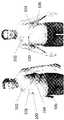
本発明は、一般に改善されたウェアラブル装置、及びかかるウェアラブル装置を使用する方法に関する。ウェアラブル装置の例には、ウェアラブル除細動器、睡眠時無呼吸に関連した症状を診断するウェアラブル装置、心不全に関連した症状を診断するウェアラブル装置を含む。本明細書に開示されたウェアラブル装置は、24時間患者によって快適に着用され得る。ウェアラブル除細動器を含むウェアラブル装置は、シャワー、睡眠、及び通常の活動中に着用できる。接着剤及び電極は、長期着用の為に設計される。ウェアラブル除細動器において、電極は、電極が皮膚と継続的に電気的に連通し、且つ除細動の為に有効量のエネルギーを送達する準備ができているように、着用されるよう設計される。 The present invention relates to generally improved wearable devices and methods of using such wearable devices. Examples of wearable devices include a wearable defibrillator, a wearable device for diagnosing symptoms associated with sleep apnea, and a wearable device for diagnosing symptoms associated with heart failure. The wearable device disclosed herein can be comfortably worn by a patient for 24 hours. Wearable devices, including wearable defibrillators, can be worn during showers, sleep, and normal activities. Adhesives and electrodes are designed for long-term wear. In a wearable defibrillator, the electrodes are designed to be worn so that the electrodes are in continuous electrical communication with the skin and are ready to deliver an effective amount of energy for defibrillation. Will be done.
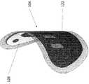
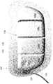
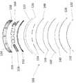
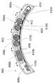
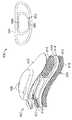
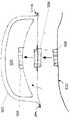
一般に、一実施態様において、ウェアラブル体外式除細動器は、心臓信号を検出する為に患者の皮膚と係合するように構成された1つ以上の検知電極と;患者の皮膚と係合し、且つ患者に電気治療を送達するように構成された第1除細動器電極パッドであって、患者の皮膚と継続的に接触するように構成された第1除細動器電極パッドと;接着剤と、第1除細動器電極パッドと、ウェアラブル体外式除細動器が継続的に着用されることを可能にする為に、流体を皮膚から離して輸送するように構成された第1流体輸送要素と、第1蒸気透過層とを含む第1患者係合基板と;第2除細動器電極パッドと、第2接着剤と、ウェアラブル体外式除細動器が継続的に着用されることを可能にする為に、流体を皮膚から離して輸送するように構成された、第2患者係合基板と流体連通した第2流体輸送要素と、第2蒸気透過層とを含む第2患者係合基板と;エネルギー源と;エネルギー源並びに第1除細動器電極パッド及び第2除細動器電極パッドと電気的に連通する1つ以上のコンデンサと;1つ以上の検知電極及び第2患者係合基板の検知電極によって心臓信号を検出し、且つエネルギー源により1つ以上のコンデンサを充電し、その後に1つ以上のコンデンサを放電して、第1及び第2患者係合基板が患者と係合される間に、第1除細動器電極パッド及び第2除細動器電極パッドを通して患者に治療ショックを送達することが続くように構成されたコントローラとを含み、エネルギー源、1つ以上のコンデンサ、及びコントローラが、1つ以上のハウジング内に封入される。 Generally, in one embodiment, the wearable extracorporeal defibrillator engages with one or more sensing electrodes configured to engage the patient's skin to detect the cardiac signal; engages with the patient's skin. And a first defibrillator electrode pad configured to deliver electrical therapy to the patient, with a first defibrillator electrode pad configured to be in continuous contact with the patient's skin; A first configured to transport fluid away from the skin to allow the adhesive, the first defibrillator electrode pad, and the wearable extracorporeal defibrillator to be worn continuously. A first patient engagement substrate comprising one fluid transport element and a first steam permeable layer; a second defibrillator electrode pad, a second adhesive, and a wearable defibrillator continuously worn. A second fluid transport element comprising fluid communication with a second patient engagement substrate and a second steam permeable layer configured to transport the fluid away from the skin to allow it to be. 2 patient engagement substrate; energy source; energy source and one or more capacitors that electrically communicate with the first defibrillator electrode pad and the second defibrillator electrode pad; one or more detection electrodes The heart signal is detected by the detection electrodes of the second patient engagement substrate, and one or more capacitors are charged by the energy source, and then one or more capacitors are discharged, so that the first and second patient engagements occur. Energy, including a controller configured to continue delivering therapeutic shock to the patient through a first defibrillator electrode pad and a second defibrillator electrode pad while the substrate is engaged with the patient. The source, one or more capacitors, and the controller are encapsulated in one or more housings.
この実施態様及び他の実施態様は、次の特徴の1つ以上を含んでも良い。第1患者係合基板は、1つ以上の検知電極を含んでも良い。第1患者係合基板は、2つ以上の検知電極を含んでも良い。第2患者係合基板は、検知電極を含んでも良い。第1除細動器電極パッド及び第2除細動器電極パッドは、心臓信号を検出するように構成され得る。1つ以上のハウジングは、第1コントローラハウジングを含んでも良く、コントローラは、第1コントローラハウジング内に含まれても良い。1つ以上のハウジングは、第1エネルギー源ハウジングを含んでも良く、エネルギー源は、第1エネルギー源ハウジング内に含まれても良い。1つ以上のハウジングは、第1コンデンサハウジングと、第2コンデンサハウジングとを含んでも良く、コンデンサは、第1コンデンサハウジング及び第2コンデンサハウジング内に含まれても良い。第1コントローラハウジングは、第1コントローラハウジング電気接続を含んでも良く、第1エネルギー源ハウジングは、第1エネルギー源ハウジング電気接続を含んでも良く、第1コンデンサハウジングは、第1コンデンサ電気接続を含んでも良く、且つ第2コンデンサハウジングは、第2電気接続を含んでも良い。ウェアラブル除細動器は、第1コントローラハウジング、第1エネルギー源ハウジング、第1コンデンサハウジング、及び第2コンデンサハウジングの各々の間の機械的接続を更に含んでも良い。ウェアラブル除細動器は、フレキシブル回路と、1つ以上のリジッドプリント回路基板(PCB)とを更に含んでも良い。フレキシブル回路は、第1コントローラハウジング電気接続、第1エネルギー源ハウジング電気接続、第1コンデンサ電気接続、及び第2電気接続を受けるように構成されても良い。フレキシブル回路は、第1コントローラハウジング、第1エネルギー源ハウジング、第1コンデンサハウジング、及び第2コンデンサハウジングと電気的に連通しても良い。 This embodiment and other embodiments may include one or more of the following features: The first patient engagement substrate may include one or more detection electrodes. The first patient engagement substrate may include two or more detection electrodes. The second patient engagement substrate may include a detection electrode. The first defibrillator electrode pad and the second defibrillator electrode pad may be configured to detect a cardiac signal. The one or more housings may include a first controller housing and the controller may be contained within the first controller housing. The one or more housings may include a first energy source housing, and the energy source may be contained within the first energy source housing. The one or more housings may include a first capacitor housing and a second capacitor housing, and the capacitors may be contained within the first capacitor housing and the second capacitor housing. The first controller housing may include a first controller housing electrical connection, the first energy source housing may include a first energy source housing electrical connection, and the first capacitor housing may include a first capacitor electrical connection. Well, the second capacitor housing may include a second electrical connection. The wearable defibrillator may further include a mechanical connection between each of the first controller housing, the first energy source housing, the first capacitor housing, and the second capacitor housing. The wearable defibrillator may further include a flexible circuit and one or more rigid printed circuit boards (PCBs). The flexible circuit may be configured to receive a first controller housing electrical connection, a first energy source housing electrical connection, a first capacitor electrical connection, and a second electrical connection. The flexible circuit may electrically communicate with the first controller housing, the first energy source housing, the first capacitor housing, and the second capacitor housing.
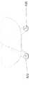
フレキシブル回路は、第1コントローラハウジング及び第1エネルギー源ハウジング、第1コンデンサハウジング、及び第2コンデンサハウジングの間に電気的連通を提供しても良い。フレキシブル回路は、第1蒸気透過層及び第1除細動器電極パッドの間で第1患者係合基板によって支持され得る。第1患者係合基板は、1つ以上のハウジングを支持するように構成され得る。第2患者係合基板は、1つ以上のハウジングを支持するように構成され得る。第1患者係合基板及び第2患者係合基板は、シャワー活動中に着用されるように構成され得る。第1患者係合基板は、外面を含んでも良く、且つ第2患者係合基板は、外面を含んでも良い。第1蒸気透過層の一部は、第1患者係合面の外面に相当しても良い。第2蒸気透過層の一部は、第2患者係合面の外面に相当しても良い。第1患者係合基板及び第2患者係合基板の外面は、水蒸気透過性であっても良い。第1患者係合基板及び第2患者係合基板の外面は、患者係合基板の表面積に基づき、1日当たり約1000g/m2を超える水蒸気輸送を有しても良い。第1患者係合基板及び第2患者係合基板の外面は、患者係合基板の表面積に基づき、1日当たり約2000g/m2を超える水蒸気輸送を有しても良い。第1患者係合基板及び第2患者係合基板の外面は、患者係合基板の表面積に基づき、1日当たり約5000g/m2を超える水蒸気輸送を有しても良い。第1患者係合基板及び第2患者係合基板の外面は、患者係合基板の表面積に基づき、1日当たり約8000g/m2を超える水蒸気輸送を有しても良い。第1患者係合基板及び第2患者係合基板の外面は、通気性であっても良い。第1患者係合基板及び第2患者係合基板の外面は、防水であっても良い。第1及び第2患者係合基板の外面は、疎水性であっても良い。第1流体輸送要素及び第2流体輸送要素は、流体を皮膚から離して輸送するように構成され得る。ウェアラブル除細動器は、1つ以上のハウジング及び第1除細動器電極パッドの間に配置される支持シャーシを更に含んでも良い。支持シャーシは、支持シャーシの主要面にわたる1つ以上のハウジングのせん断荷重を分散させるように構成できる。ウェアラブル除細動器は、患者の胸部上の一点で患者の血液の酸素含有量を測定するように構成されたパルスオキシメータを更に含んでも良い。ウェアラブル除細動器は、超音波信号を伝送し、且つ/又は受信するように構成された超音波トランシーバ又はトランスデューサを更に含んでも良い。ウェアラブル除細動器は、マイクロ波信号を伝送し、且つ返信されたマイクロ波信号を受信するように構成されたドップラーレーダを更に含んでも良い。第1除細動器電極パッドは、第1電極対を含んでも良い。コントローラは、第1電極対の間の第1インピーダンスを測定するように構成され得る。コントローラは、第1電極対が、患者の皮膚と適切に接触しているか否かを判定する為に第1インピーダンスを分析するように構成され得る。第2除細動器電極パッドは、第2電極対を含んでも良い。コントローラは、第2電極対の間の第2インピーダンスを測定するように構成され得る。コントローラは、第2電極対が、患者の皮膚と適切に接触しているか否かを判定する為に第2インピーダンスを分析するように構成され得る。コントローラは、第1電極対及び第2電極対の間の経胸腔インピーダンスを測定するように構成され得る。ウェアラブル除細動器は、ハウジング及び接着剤の間の相対運動を可能にするように構成された、ハウジング及び接着剤の間に配置されたスリップ層を更に含んでも良い。ウェアラブル除細動器は、エネルギー源、1つ以上のコンデンサ、及びコントローラを封入する第1シール層を更に含んでも良い。第1シール層は、ハウジング内部にあっても良い。第1シール層は、ハウジングに接触しても良い。ウェアラブル除細動器は、ハウジングを含む第2シール層を更に含んでも良い。ウェアラブル除細動器は、複数の電気接続を有する、ハウジング上のコネクタプラグを更に含んでも良い。複数の電気接続は、第1除細動器電極パッド接続及び第2除細動器電極パッド接続を含んでも良い。第1除細動器電極パッド接続及び第2除細動器電極パッド接続は、1つ以上のコンデンサ並びに第1及び第2除細動器電極パッドと電気的に連通するように構成され得る。複数の電気接続は、複数の検知電極接続を含んでも良い。複数の検知電極接続は、各々がコントローラ及び1つ以上の検知電極の1つと電気的に連通するように構成され得る。ウェアラブル除細動器は、ハウジングを取り囲むように構成されたエンクロージャを更に含んでも良く、エンクロージャは、エンクロージャ接続を含んでも良く、且つハウジング上のコネクタプラグと係合するように構成された相補的構造を有する第1側面を有しても良い。ウェアラブル除細動器は、第1患者係合基板上の患者係合基板コネクタ、1つ以上のコンデンサと電気的に連通する患者係合基板コネクタ、並びに第1及び第2除細動器電極パッドと係合するように構成されたエンクロージャ接続の第2側面を更に含んでも良い。接着剤は、水蒸気の輸送を可能にするように構成された複数の孔を含んでも良い。1つ以上の検知電極及び除細動器電極パッドは、水蒸気の輸送を可能にするように構成された複数の孔を含んでも良い。第1除細動器電極パッド第2除細動器電極パッドは、導電性インクコーティングを有するポリエチレンテレフタレート(PET)基板を含んでも良い。第1除細動器電極パッドは、第1導電性接着剤と、第1導電性電極とを含んでも良い。第2除細動器電極パッドは、第2導電性接着剤と、第2導電性電極とを含んでも良い。第1及び第2導電性電極は、中実構成を有しても良い。第1及び第2導電性電極は、複数の穿孔を有する可撓性シートから作られていても良い。第1及び第2導電性電極は、炭素ビニルフィルム、Ag/AgCl被覆炭素ビニルフィルム、又はAg被覆炭素ビニルフィルムを含んでも良い。第1及び第2除細動器電極パッドの第1及び第2導電性電極は、織物構造を有しても良い。第1及び第2除細動器電極パッドの第1及び第2導電性電極は、炭素繊維を含んでも良い。第1導電性接着剤及び第2導電性接着剤は、導電性ヒドロゲルを含んでも良い。導電性ヒドロゲルは、塩を含んでも良い。第1導電性接着剤及び第2導電性接着剤は、導電性充填剤を有する接着剤を含んでも良い。導電性充填材は、カーボンナノチューブ、グラフェン、カーボンブラック、銀粒子、金属粒子、及び銀ナノワイヤの1つ以上を含んでも良い。第1患者係合基板は、1つ以上の検知電極及び第1除細動器電極パッドの間を絶縁するように構成され得る。第2患者係合基板は、検知電極及び第2除細動器電極パッドの間を絶縁するように構成され得る。第1及び第2患者係合基板上の接着剤は、非導電性であっても良い。ウェアラブル除細動器は、ウェアラブル除細動器の位置及び配向を判定するように構成された傾斜計を更に含んでも良い。ウェアラブル除細動器は、ウェアラブル除細動器の場所を伝送するように構成された無線標識を更に含んでも良い。ウェアラブル除細動器は、GPSセンサを更に含んでも良い。ウェアラブル除細動器は、ウェアラブル除細動器からのデータを無線伝送するように構成された無線通信機を更に含んでも良い。無線通信機は、セルラネットワークを介してデータを伝送するように構成しても良い。ウェアラブル除細動器は、ウェアラブル除細動器の一部の機械的伸張を測定するように構成されたセンサを更に含んでも良い。1つ以上のコンデンサは、ウェアラブル除細動器と可逆的且つ取り外し可能に係合されるように構成され得る。エネルギー源は、ウェアラブル除細動器と可逆的且つ取り外し可能に係合されるように構成され得る。コントローラは、ウェアラブル除細動器と可逆的且つ取り外し可能に係合されるように構成され得る。ウェアラブル除細動器は、第1患者係合基板上の接着剤を覆うように構成された第1接着剤剥離ライナを更に含んでも良い。ウェアラブル除細動器は、第2患者係合基板上の接着剤を覆うように構成された第2接着剤剥離ライナを更に含んでも良い。ハウジングは、複数のエネルギー源を受けるように構成され得る。エネルギー源は、第1モジュール電池と、第2モジュール電池とを含んでも良く、第1及び第2モジュール電池は、ハウジング内部に取り外し可能に受けられるように構成され得る。ウェアラブル除細動器は、ペーシング信号を患者に提供するように構成された外部ペーシングモジュールを更に含んでも良く、外部ペーシングモジュールは、第1又は第2患者係合基板によって支持され得る。ウェアラブル除細動器は、患者の皮膚からの第1及び/又は第2患者係合基板の取り外しを検知するように構成された皮膚接触モジュールを更に含んでも良い。皮膚接触モジュールは、患者の皮膚からの第1及び/又は第2患者係合基板の取り外しを検知すると、医療サービス提供者に警報及び/又は通知を生成するように構成され得る。ウェアラブル除細動器は、ハウジング及び第1患者係合基板に結合されたカンチレバを更に含んでも良い。ハウジングは、エネルギー源と、1つ以上のコンデンサと、コントローラとを含む複数の区画を含んでも良い。ウェアラブル除細動器は、ハウジング内部にフレキシブル回路と、1つ以上のリジッドプリント回路基板(PCB)とを更に含んでも良い。複数の区画は、ハウジング内部で流体連通しても良い。複数の区画は、複数の区画の他の区画と流体連通しなくても良い。複数の区画は、分離しており、且つ複数の区画の他の区画と可逆的に係合するように構成され得る。複数の区画は、複数の防水コネクタセグメントに接続され得る。ハウジングは、ハウジングの複数の区画間の相対運動を可能にするように構成され得る。相対運動は、第1患者係合基板の平面による屈曲を含んでも良い。ハウジングは、外部クラムシェルと、基部とを含んでも良い。外部クラムシェルは、基部に超音波溶接され得る。外部クラムシェルは、接着剤によって基部に取り付けられ得る。外部クラムシェルは、化学結合を通じて基部に取り付けられ得る。第1患者係合基板の1つ以上の検知電極及び第2患者係合基板の検知電極並びに第1及び第2除細動器電極パッドは、患者の複数のベクトルに沿ったインピーダンス変化を検知するように構成でき、コントローラは、患者の心臓の健康を測定する為に、患者の複数のベクトルに沿ったインピーダンス変化を分析するように構成され得る。第1患者係合基板は、1つ以上の検知電極と、接着剤と、第1除細動器電極パッドとを含む患者係合部を含んでも良い。第1患者係合基板は、患者係合部及び第1蒸気透過層を通して、患者係合部の表面積に基づき、1日当たり約100g/m2を超える水蒸気輸送を含んでも良い。第1患者係合基板は、患者係合部及び第1蒸気透過層を通して、患者係合部の表面積に基づき、1日当たり約500g/m2を超える水蒸気輸送を含んでも良い。第1患者係合基板は、患者係合部及び第1蒸気透過層を通して、患者係合部の表面積に基づき、1日当たり約1000g/m2を超える水蒸気輸送を含んでも良い。第1患者係合基板は、患者係合部及び第1蒸気透過層を通して、患者係合部の表面積に基づき、1日当たり約1500g/m2を超える水蒸気輸送を含んでも良い。第2患者係合基板は、検知電極と、第2接着剤と、第2除細動器電極パッドとを含む第2患者係合部を含んでも良い。第1患者係合基板は、第2患者係合部及び第2蒸気透過層を通して、患者係合部の表面積に基づき、1日当たり約100g/m2を超える水蒸気輸送を含んでも良い。第1患者係合基板は、第2患者係合部及び第2蒸気透過層を通して、患者係合部の表面積に基づき、1日当たり約500g/m2を超える水蒸気輸送を含んでも良い。第1患者係合基板は、第2患者係合部及び第2蒸気透過層を通して、患者係合部の表面積に基づき、1日当たり約1000g/m2を超える水蒸気輸送を含んでも良い。第1患者係合基板は、第2患者係合部及び第2蒸気透
過層を通して、患者係合部の表面積に基づき、1日当たり約1500g/m2を超える水蒸気輸送を含んでも良い。第1患者係合基板は、予め形成された湾曲を有しても良い。予め形成された湾曲は、人間の胴体の形状に対応しても良い。第2患者係合基板は、予め形成された湾曲を有しても良い。予め形成された湾曲は、人間の胸部の形状に対応しても良い。ウェアラブル除細動器は、第1患者係合基板及び第2患者係合基板の間に電気的連通を形成するケーブルを更に含んでも良い。ケーブルは、第2患者係合基板の検知電極及びコントローラの間に電気的連通を形成しても良い。ケーブルは、第2除細動器電極パッド及び1つ以上のコンデンサの間に電気的連通を形成しても良い。ウェアラブル除細動器は、表示インジケータを更に含んでも良い。表示インジケータは、第1患者係合基板又は第2患者係合基板の一部であっても良い。表示インジケータは、1つ以上のハウジングの一部であっても良い。表示インジケータは、第1患者係合基板又は第2患者係合基板の間のケーブルの一部であっても良い。表示インジケータは、発光ダイオード(LED)であっても良い。ウェアラブル除細動器は、触覚フィードバックモジュールを更に含んでも良い。触覚フィードバックモジュールは、第1患者係合基板又は第2患者係合基板の一部であっても良い。触覚フィードバックモジュールは、1つ以上のハウジングの一部であっても良い。触覚フィードバックモジュールは、振動モータであっても良い。ウェアラブル除細動器は、1つ以上のハウジング上に1つ以上のボタンを更に含んでも良い。ウェアラブル除細動器は、ハウジング及び第1患者係合基板の間の第1接続と、ハウジング及び第1患者係合基板の間の第2可撓性接続とを更に含んでも良く、第1接続は、第1患者係合基板の第1端部上にあっても良く、且つ第2可撓性接続は、第1患者係合基板の第1端部に対向する第1患者係合基板の第2端部上にあっても良い。第2可撓性接続は、第1患者係合基板の第2端部及びハウジングの間の相対運動を可能にしても良い。ウェアラブル除細動器は、第1患者係合基板上の1つ以上の検知電極を覆うように構成された第1検知電極剥離ライナと、第1除細動器電極パッドを覆うように構成された第1除細動器電極パッド剥離ライナとを更に含んでも良い。ウェアラブル除細動器は、第2患者係合基板上の1つ以上の検知電極を覆うように構成された第2検知電極剥離ライナと、第2除細動器電極パッドを覆うように構成された第2除細動器電極パッド剥離ライナとを更に含んでも良い。ハウジングは、2つ以上の患者係合基板によって支持され得る。ウェアラブル除細動器は、電気活性ポリマーを更に含んでも良い。電気活性ポリマーは、第1患者係合基板及び/又は第2患者係合基板の形態の変化を検出するように構成され得る。電気活性ポリマーは、振動するように構成され得る。電気活性ポリマーは、変形して、第1及び/又は第2患者係合基板の形態を変化させるように構成され得る。ウェアラブル除細動器は、ハウジング及びハウジング内部の部品の重量を支持するように構成された、第1患者係合基板及びハウジングの間の可撓性接続を更に含んでも良い。可撓性接続は、ハウジング及び第1患者係合基板の間の相対運動を可能にしても良い。可撓性接続は、ハウジング及び第1患者係合基板の間の1つ以上の電気接続を更に含んでも良い。可撓性接続は、取り外し可能で、且つ可逆的な接続を含んでも良い。1つ以上のハウジングは、各々が接着剤によって密封されるクラムシェル形態を有しても良い。1つ以上のハウジングは、各々が超音波溶接によって密封されるクラムシェル形態を有しても良い。1つ以上のハウジングは、各々が化学結合を通して密封されるクラムシェル形態を有しても良い。コントローラは、1つ以上の検知電極、第1除細動器電極パッド、第2除細動器電極パッド、及び検知電極の1つ以上の間のインピーダンスを分析するように構成され得る。コントローラは、2つ以上の離散周波数を使用して、インピーダンスを測定するように更に構成され得る。2つ以上の離散周波数は、高周波測定と、低周波測定とを含んでも良い。コントローラは更に、高周波測定と、低周波測定とを分析し、インピーダンスに基づき患者の治療ショックの仕事率を判定するように構成され得る。ウェアラブル除細動器は、温度センサを更に含んでも良い。The flexible circuit may provide electrical communication between the first controller housing and the first energy source housing, the first capacitor housing, and the second capacitor housing. The flexible circuit may be supported by a first patient engagement substrate between the first vapor permeable layer and the first defibrillator electrode pad. The first patient engagement substrate may be configured to support one or more housings. The second patient engagement substrate may be configured to support one or more housings. The first patient engagement substrate and the second patient engagement substrate may be configured to be worn during shower activity. The first patient engaging substrate may include an outer surface, and the second patient engaging substrate may include an outer surface. A part of the first vapor permeable layer may correspond to the outer surface of the first patient engaging surface. A part of the second vapor permeable layer may correspond to the outer surface of the second patient engaging surface. The outer surfaces of the first patient engaging substrate and the second patient engaging substrate may be water vapor permeable. The outer surfaces of the first patient engagement substrate and the second patient engagement substrate may have water vapor transport of more thanabout 1000 g / m 2 per day based on the surface area of the patient engagement substrate. The outer surfaces of the first patient engagement substrate and the second patient engagement substrate may have water vapor transport of more thanabout 2000 g / m 2 per day based on the surface area of the patient engagement substrate. The outer surfaces of the first patient engagement substrate and the second patient engagement substrate may have more thanabout 5000 g / m 2 of water vapor transport per day based on the surface area of the patient engagement substrate. The outer surfaces of the first patient engagement substrate and the second patient engagement substrate may have more thanabout 8000 g / m 2 of water vapor transport per day based on the surface area of the patient engagement substrate. The outer surfaces of the first patient engaging substrate and the second patient engaging substrate may be breathable. The outer surfaces of the first patient engaging substrate and the second patient engaging substrate may be waterproof. The outer surface of the first and second patient engagement substrates may be hydrophobic. The first fluid transport element and the second fluid transport element may be configured to transport the fluid away from the skin. The wearable defibrillator may further include a support chassis located between one or more housings and a first defibrillator electrode pad. The support chassis can be configured to distribute the shear load of one or more housings over the main surface of the support chassis. The wearable defibrillator may further include a pulse oximeter configured to measure the oxygen content of the patient's blood at a point on the patient's chest. The wearable defibrillator may further include an ultrasonic transceiver or transducer configured to transmit and / or receive an ultrasonic signal. The wearable defibrillator may further include a Doppler radar configured to transmit the microwave signal and receive the returned microwave signal. The first defibrillator electrode pad may include a first pair of electrodes. The controller may be configured to measure the first impedance between the first pair of electrodes. The controller may be configured to analyze the first impedance to determine if the first electrode pair is in proper contact with the patient's skin. The second defibrillator electrode pad may include a second pair of electrodes. The controller may be configured to measure the second impedance between the second electrode pair. The controller may be configured to analyze the second impedance to determine if the second electrode pair is in proper contact with the patient's skin. The controller may be configured to measure the transthoracic impedance between the first and second electrode pairs. The wearable defibrillator may further include a slip layer disposed between the housing and the adhesive that is configured to allow relative movement between the housing and the adhesive. The wearable defibrillator may further include an energy source, one or more capacitors, and a first seal layer that encloses the controller. The first seal layer may be inside the housing. The first seal layer may be in contact with the housing. The wearable defibrillator may further include a second seal layer that includes a housing. The wearable defibrillator may further include a connector plug on the housing that has multiple electrical connections. The plurality of electrical connections may include a first defibrillator electrode pad connection and a second defibrillator electrode pad connection. The first defibrillator electrode pad connection and the second defibrillator electrode pad connection may be configured to electrically communicate with one or more capacitors and the first and second defibrillator electrode pads. The plurality of electrical connections may include multiple detection electrode connections. The plurality of detection electrode connections may be configured such that each communicates electrically with the controller and one of the one or more detection electrodes. The wearable defibrillator may further include an enclosure configured to surround the housing, the enclosure may include an enclosure connection, and a complementary structure configured to engage a connector plug on the housing. It may have the first side surface which has. The wearable defibrillator is a patient engagement board connector on a first patient engagement board, a patient engagement board connector that electrically communicates with one or more capacitors, and first and second defibrillator electrode pads. It may further include a second aspect of the enclosure connection configured to engage with. The adhesive may include a plurality of holes configured to allow the transport of water vapor. The one or more detection electrodes and defibrillator electrode pads may include a plurality of holes configured to allow the transport of water vapor. First Defibrillator Electrode Pad The second defibrillator electrode pad may include a polyethylene terephthalate (PET) substrate with a conductive ink coating. The first defibrillator electrode pad may include a first conductive adhesive and a first conductive electrode. The second defibrillator electrode pad may include a second conductive adhesive and a second conductive electrode. The first and second conductive electrodes may have a solid structure. The first and second conductive electrodes may be made of a flexible sheet having a plurality of perforations. The first and second conductive electrodes may include a carbon vinyl film, an Ag / AgCl coated carbon vinyl film, or an Ag coated carbon vinyl film. The first and second conductive electrodes of the first and second defibrillator electrode pads may have a woven structure. The first and second conductive electrodes of the first and second defibrillator electrode pads may contain carbon fibers. The first conductive adhesive and the second conductive adhesive may contain a conductive hydrogel. The conductive hydrogel may contain a salt. The first conductive adhesive and the second conductive adhesive may contain an adhesive having a conductive filler. The conductive filler may include one or more of carbon nanotubes, graphene, carbon black, silver particles, metal particles, and silver nanowires. The first patient engagement substrate may be configured to insulate between one or more sensing electrodes and a first defibrillator electrode pad. The second patient engagement substrate may be configured to insulate between the detection electrode and the second defibrillator electrode pad. The adhesive on the first and second patient engagement substrates may be non-conductive. The wearable defibrillator may further include an inclinometer configured to determine the position and orientation of the wearable defibrillator. The wearable defibrillator may further include a radio beacon configured to transmit the location of the wearable defibrillator. The wearable defibrillator may further include a GPS sensor. The wearable defibrillator may further include a wireless communicator configured to wirelessly transmit data from the wearable defibrillator. The wireless communication device may be configured to transmit data via a cellular network. The wearable defibrillator may further include a sensor configured to measure the mechanical extension of a portion of the wearable defibrillator. One or more capacitors may be configured to be reversibly and removably engaged with a wearable defibrillator. The energy source may be configured to be reversibly and removably engaged with a wearable defibrillator. The controller may be configured to engage reversibly and removably with the wearable defibrillator. The wearable defibrillator may further include a first adhesive release liner configured to cover the adhesive on the first patient engagement substrate. The wearable defibrillator may further include a second adhesive stripping liner configured to cover the adhesive on the second patient engagement substrate. The housing may be configured to receive multiple sources of energy. The energy source may include a first module battery and a second module battery, the first and second module batteries may be configured to be removable inside the housing. The wearable defibrillator may further include an external pacing module configured to provide a pacing signal to the patient, which may be supported by a first or second patient engagement substrate. The wearable defibrillator may further include a skin contact module configured to detect the removal of the first and / or second patient engagement substrate from the patient's skin. The skin contact module may be configured to generate an alarm and / or notification to the medical service provider upon detecting the removal of the first and / or second patient engagement substrate from the patient's skin. The wearable defibrillator may further include a cantilever coupled to the housing and first patient engagement substrate. The housing may include a plurality of compartments including an energy source, one or more capacitors, and a controller. The wearable defibrillator may further include a flexible circuit and one or more rigid printed circuit boards (PCBs) inside the housing. The plurality of compartments may be fluid communication inside the housing. The plurality of compartments does not have to communicate with other compartments of the plurality of compartments. The plurality of compartments may be configured to be separate and reversibly engage with the other compartments of the plurality of compartments. Multiple compartments may be connected to multiple waterproof connector segments. The housing may be configured to allow relative motion between multiple compartments of the housing. The relative motion may include bending of the first patient engagement substrate by a plane. The housing may include an external clamshell and a base. The external clamshell can be ultrasonically welded to the base. The external clamshell can be attached to the base by an adhesive. The outer clamshell can be attached to the base through chemical bonds. One or more detection electrodes on the first patient engagement substrate, detection electrodes on the second patient engagement substrate, and first and second defibrillator electrode pads detect changes in impedance along multiple patient vectors. The controller can be configured to analyze impedance changes along multiple vectors of the patient in order to measure the patient's heart health. The first patient engagement substrate may include a patient engagement portion comprising one or more detection electrodes, an adhesive, and a first defibrillator electrode pad. The first patient engagement substrate may contain more thanabout 100 g / m 2 of water vapor per day based on the surface area of the patient engagement portion through the patient engagement portion and the first vapor permeation layer. The first patient engagement substrate may contain more thanabout 500 g / m 2 of water vapor per day based on the surface area of the patient engagement portion through the patient engagement portion and the first vapor permeation layer. The first patient engagement substrate may contain more thanabout 1000 g / m 2 of water vapor per day based on the surface area of the patient engagement portion through the patient engagement portion and the first vapor permeation layer. The first patient engagement substrate may contain more thanabout 1500 g / m 2 of water vapor per day based on the surface area of the patient engagement portion through the patient engagement portion and the first vapor permeation layer. The second patient engagement substrate may include a second patient engagement portion that includes a detection electrode, a second adhesive, and a second defibrillator electrode pad. The first patient engagement substrate may contain more thanabout 100 g / m 2 of water vapor per day based on the surface area of the patient engagement portion through the second patient engagement portion and the second vapor permeation layer. The first patient engagement substrate may contain more thanabout 500 g / m 2 of water vapor per day based on the surface area of the patient engagement portion through the second patient engagement portion and the second vapor permeation layer. The first patient engagement substrate may contain more thanabout 1000 g / m 2 of water vapor per day based on the surface area of the patient engagement portion through the second patient engagement portion and the second vapor permeation layer. The first patient engagement substrate may contain more thanabout 1500 g / m 2 of water vapor per day based on the surface area of the patient engagement portion through the second patient engagement portion and the second vapor permeation layer. The first patient engagement substrate may have a preformed curve. The preformed curvature may correspond to the shape of the human torso. The second patient engagement substrate may have a preformed curvature. The preformed curvature may correspond to the shape of the human chest. The wearable defibrillator may further include a cable that forms an electrical connection between the first patient engagement substrate and the second patient engagement substrate. The cable may form electrical communication between the detection electrode of the second patient engagement substrate and the controller. The cable may form an electrical communication between the second defibrillator electrode pad and one or more capacitors. The wearable defibrillator may further include a display indicator. The display indicator may be part of a first patient engagement board or a second patient engagement board. The display indicator may be part of one or more housings. The display indicator may be part of a cable between the first patient engagement board or the second patient engagement board. The display indicator may be a light emitting diode (LED). The wearable defibrillator may further include a tactile feedback module. The tactile feedback module may be part of a first patient engagement board or a second patient engagement board. The haptic feedback module may be part of one or more housings. The haptic feedback module may be a vibration motor. The wearable defibrillator may further include one or more buttons on one or more housings. The wearable defibrillator may further include a first connection between the housing and the first patient engagement substrate and a second flexible connection between the housing and the first patient engagement substrate, the first connection. May be on the first end of the first patient engagement substrate, and the second flexible connection is of the first patient engagement substrate facing the first end of the first patient engagement substrate. It may be on the second end. The second flexible connection may also allow relative movement between the second end of the first patient engagement substrate and the housing. The wearable defibrillator is configured to cover a first detection electrode peeling liner configured to cover one or more detection electrodes on a first patient engagement substrate and a first defibrillator electrode pad. It may further include a first defibrillator electrode pad peeling liner. The wearable defibrillator is configured to cover a second detection electrode peeling liner configured to cover one or more detection electrodes on a second patient engagement substrate and a second defibrillator electrode pad. Further may include a second defibrillator electrode pad peeling liner. The housing may be supported by more than one patient engagement substrate. The wearable defibrillator may further contain an electroactive polymer. The electroactive polymer may be configured to detect morphological changes in the first patient engagement substrate and / or the second patient engagement substrate. The electroactive polymer can be configured to vibrate. The electroactive polymer can be modified to change the morphology of the first and / or second patient engagement substrate. The wearable defibrillator may further include a flexible connection between the first patient engagement substrate and the housing configured to support the weight of the housing and components within the housing. Flexible connections may also allow relative movement between the housing and the first patient engagement substrate. The flexible connection may further include one or more electrical connections between the housing and the first patient engagement substrate. Flexible connections may include removable and reversible connections. The one or more housings may have a clamshell form, each sealed with an adhesive. The one or more housings may have a clamshell form, each sealed by ultrasonic welding. The one or more housings may have a clamshell form, each sealed through a chemical bond. The controller may be configured to analyze the impedance between one or more detection electrodes, a first defibrillator electrode pad, a second defibrillator electrode pad, and one or more of the detection electrodes. The controller may be further configured to measure impedance using two or more discrete frequencies. The two or more discrete frequencies may include high frequency measurements and low frequency measurements. The controller may be further configured to analyze high frequency and low frequency measurements and determine the power of the patient'stherapeutic shock based on impedance. The wearable defibrillator may further include a temperature sensor.
一般に、一実施態様において、患者の心臓を監視及び除細動を行う方法は、第1の複数の検知電極と、第1除細動器電極パッドとを含む第1患者係合基板を、患者の第1皮膚表面部に接着し、第1除細動器電極パッドが、除細動ショックを提供する為に十分な電気エネルギー源と電気的に連通し、ウェアラブル除細動器の第1患者係合基板部分が、流体を患者の第1皮膚表面部から離して輸送し、ウェアラブル体外式除細動器が継続的に着用されることを可能にするように構成された流体輸送要素を含むこと;検知電極と、第2除細動器電極パッドとを含む第2患者係合基板を患者の第2皮膚表面部に接着し、第2除細動器電極パッドが、除細動ショックを提供する為に十分な電気エネルギー源と電気的に連通し、ウェアラブル除細動器の第2患者係合基板部分、ウェアラブル除細動器が、患者の脈拍、血液の酸素含有量、インピーダンス、ガルバニック皮膚インピーダンス、体温、呼吸数、心音及び心拍数の1つ以上を検出するように構成される1つ以上のセンサを含むこと;第1の複数の検知電極、第2患者係合基板の検知電極、及び/又はウェアラブル除細動器のセンサにより、患者の心臓信号又は他の特性に対応する患者データを測定すること;及び患者データを分析して、患者が不整脈を有するか否かを判定することを含む。 Generally, in one embodiment, a method of monitoring and defibrillating a patient's heart involves a first patient engagement substrate comprising a first plurality of detection electrodes and a first defibrillator electrode pad. The first patient of the wearable defibrillator, which adheres to the surface of the first skin of the body and the first defibrillator electrode pad electrically communicates with a sufficient electrical energy source to provide a defibrillation shock. Engagement substrate portion comprises a fluid transport element configured to transport fluid away from the patient's first skin surface and allow the wearable extracorporeal defibrillator to be continuously worn. That; the second patient engagement substrate, including the detection electrode and the second defibrillator electrode pad, is adhered to the patient's second skin surface and the second defibrillator electrode pad provides a defibrillator shock. Electrically communicated with a sufficient electrical energy source to provide, the second patient engagement substrate portion of the wearable defibrillator, the wearable defibrillator, the patient's pulse, blood oxygen content, impedance, galvanic Includes one or more sensors configured to detect one or more of skin impedance, body temperature, breath rate, heartbeat and heart rate; first plurality of detection electrodes, second patient engagement substrate detection electrodes And / or measure patient data corresponding to the patient's heart signal or other characteristics with a wearable defibrillator sensor; and analyze the patient data to determine if the patient has an arrhythmia. Including that.
この実施態様及び他の実施態様は、次の特徴の1つ以上を含んでも良い。方法は、不整脈の検出時に、ウェアラブル除細動器上の1つ以上のセンサを使用して患者の脈拍、血液の酸素含有量、インピーダンス、ガルバニック皮膚インピーダンス、体温、呼吸数、心音及び心拍数の1つ以上を検出すること;及び患者の脈拍、血液の酸素含有量、呼吸数、心音及び心拍数の検出された1つ以上を分析して、不整脈の有無を確認することを更に含んでも良い。方法は、第1患者係合基板の1つ以上の検知電極及び第2患者係合基板の検知電極並びに第1及び第2除細動器電極パッドによって、患者の複数のベクトルに沿ったインピーダンス変化を検知することを更に含んでも良い。方法は、インピーダンス変化を患者の基準値及び/又はデータベースと比較し、患者の心臓の健康を測定することを更に含んでも良い。方法は、第1の複数の検知電極及び第2患者係合基板の検知電極によって患者の心臓信号に対応する電気データを測定することを更に含んでも良い。方法は、ウェアラブル除細動器上のマイクロフォンによって、患者の呼吸数、心音及び心拍数の1つ以上を検出することを更に含んでも良い。方法は、不整脈の検出時に、ウェアラブル除細動器と一体化された加速度計によって患者の動きを記録すること;及び記録された患者の動きを分析して、不整脈の有無を確認することを更に含んでも良い。方法は、ウェアラブル除細動器上のパルスオキシメータによって血液の酸素含有量を検出することを更に含んでも良い。ウェアラブル除細動器上のパルスオキシメータによって血液の酸素含有量を検出することは、患者の胸部上の一点で患者の血液の酸素含有量を測定することを含んでも良い。方法は、第1除細動器電極パッド及び第2除細動器電極パッドの間の経胸腔インピーダンスを測定することを更に含んでも良い。第1除細動器電極パッドは、2つの別個の電極を含んでも良く、第1除細動器電極パッドの2つの別個の電極間のインピーダンスを測定することを更に含んでも良い。方法は、第1除細動器電極パッドの2つの別個の電極間のインピーダンスを分析して、第1除細動器電極パッドの2つの別個の電極が、電気ショックを送達する為に、皮膚と十分に電気的に接触しているか否かを判定することを更に含んでも良い。第2除細動器電極パッドは、2つの別個の電極を含んでも良く、第2除細動器電極パッドの2つの別個の電極間のインピーダンスを測定することを更に含んでも良い。方法は、第2除細動器電極パッドの2つの別個の電極間のインピーダンスを分析して、第2除細動器電極パッドの2つの別個の電極が、電気ショックを送達する為に、皮膚と十分に電気的に接触しているか否かを判定することを更に含んでも良い。方法は、患者が不整脈を有すると判定した後に電気ショックを送達することを更に含んでも良い。方法は、徐脈、心房細動、収縮不全、心臓ブロック、休止、心室頻脈、心室細動、異常を伴う頻脈、又は上室性頻脈(SVT)に関する患者の心臓信号に対応する測定された電気データを分析することを更に含んでも良い。方法は、ウェアラブル除細動器を約24時間より長く継続的に着用することを更に含んでも良い。方法は、ウェアラブル除細動器を約5日間より長く継続的に着用することを更に含んでも良い。方法は、ウェアラブル除細動器を約7日間より長く継続的に着用することを更に含んでも良い。方法は、ウェアラブル除細動器を約10日間より長く継続的に着用することを更に含んでも良い。方法は、ウェアラブル除細動器を約14日間より長く継続的に着用することを更に含んでも良い。 This embodiment and other embodiments may include one or more of the following features: The method uses one or more sensors on a wearable defibrillator when detecting an arrhythmia to determine the patient's pulse, blood oxygen content, impedance, galvanic skin impedance, body temperature, respiratory rate, heart rate and heart rate. It may further include detecting one or more; and analyzing one or more of the detected one or more of the patient's pulse, blood oxygen content, respiratory rate, heart rate and heart rate to confirm the presence or absence of arrhythmia. .. The method is to change the impedance along multiple vectors of the patient by means of one or more detection electrodes on the first patient engagement substrate, detection electrodes on the second patient engagement substrate, and first and second defibrillator electrode pads. May further include detecting. The method may further include comparing impedance changes to patient reference values and / or databases to measure patient heart health. The method may further include measuring electrical data corresponding to the patient's cardiac signal by means of a first plurality of sensing electrodes and a second patient engaging substrate sensing electrode. The method may further include detecting one or more of the patient's respiratory rate, heart sounds and heart rate by means of a microphone on a wearable defibrillator. The method is to record the patient's movements with an accelerometer integrated with a wearable defibrillator upon detection of the arrhythmia; and further analyze the recorded patient movements to confirm the presence or absence of the arrhythmia. It may be included. The method may further include detecting the oxygen content of the blood with a pulse oximeter on a wearable defibrillator. Detecting the oxygen content of blood with a pulse oximeter on a wearable defibrillator may include measuring the oxygen content of the patient's blood at a point on the patient's chest. The method may further comprise measuring the transthoracic impedance between the first defibrillator electrode pad and the second defibrillator electrode pad. The first defibrillator electrode pad may include two separate electrodes and may further include measuring the impedance between the two separate electrodes of the first defibrillator electrode pad. The method analyzes the impedance between two separate electrodes of the first defibrillator electrode pad so that the two separate electrodes of the first defibrillator electrode pad deliver an electrical shock to the skin. It may further include determining whether or not there is sufficient electrical contact with. The second defibrillator electrode pad may include two separate electrodes and may further include measuring the impedance between the two separate electrodes of the second defibrillator electrode pad. The method analyzes the impedance between two separate electrodes of the second defibrillator electrode pad, and the two separate electrodes of the second defibrillator electrode pad deliver an electric shock to the skin. It may further include determining whether or not there is sufficient electrical contact with. The method may further include delivering an electric shock after determining that the patient has an arrhythmia. The method measures the patient's cardiac signals for bradycardia, atrial fibrillation, systolic dysfunction, cardiac block, rest, ventricular tachycardia, ventricular fibrillation, tachycardia with abnormalities, or supraventricular tachycardia (SVT). It may further include analyzing the generated electrical data. The method may further include wearing the wearable defibrillator continuously for longer than about 24 hours. The method may further include wearing the wearable defibrillator continuously for longer than about 5 days. The method may further include wearing the wearable defibrillator continuously for longer than about 7 days. The method may further include wearing the wearable defibrillator continuously for longer than about 10 days. The method may further include wearing the wearable defibrillator continuously for longer than about 14 days.
一般に、一実施態様において、ウェアラブル除細動器を修復する方法は、エネルギー源と、コントローラと、ウェアラブル除細動器が患者によって着用された間に収集された患者データセットを含むメモリとを含むウェアラブル除細動器を受けること;患者データセットをメモリからウェアラブル除細動器の外部のコンピュータネットワーク又はシステムにコピーすること;患者データセットをウェアラブル除細動器のメモリから消去すること;ウェアラブル除細動器のエネルギー源を再充電又は取り替えること;及び患者データセットを消去し、且つエネルギー源を再充電又は取り替えた後にウェアラブル除細動器に関して診断テストを実行することを含む。 Generally, in one embodiment, a method of repairing a wearable defibrillator comprises an energy source, a controller, and a memory containing a patient data set collected while the wearable defibrillator was worn by the patient. Receiving a wearable defibrillator; copying the patient data set from memory to a computer network or system outside the wearable defibrillator; erasing the patient data set from the wearable defibrillator memory; wearable defibrillator Recharging or replacing the defibrillator's energy source; and erasing the patient dataset and performing diagnostic tests on the wearable defibrillator after recharging or replacing the energy source.
この実施態様及び他の実施態様は、次の特徴の1つ以上を含んでも良い。ウェアラブル除細動器は、本明細書に記載されたウェアラブル除細動器のいずれかであっても良い。ウェアラブル除細動器は、心臓信号を検出する為に患者の皮膚と係合するように構成された1つ以上の検知電極と;患者の皮膚と係合し、且つ電気治療を患者に送達するように構成された除細動器電極パッドと;接着剤と、1つ以上の検知電極と、除細動器電極パッドとを含む患者係合基板と;エネルギー源及び除細動器電極パッドと電気的に連通する1つ以上のコンデンサとを更に含んでも良く、コントローラは、検知電極によって心臓信号を検出し、且つ1つ以上のコンデンサをエネルギー源で充電し、その後に1つ以上のコンデンサを放電して、患者係合基板が患者と係合される間に、治療ショックを除細動器電極パッドを通して患者に送達するように構成される。ウェアラブル除細動器は、1つ以上のコンデンサと、エネルギー源と、コントローラとを含む1つ以上のモジュールを含んでも良い。ウェアラブル除細動器は、エネルギー源を含むモジュールを含んでも良く、且つエネルギー源を取り替えることは、エネルギー源を含むモジュールを取り替えることを含む。診断テストは、1つ以上のコンデンサ、メモリ、エネルギー源、及びコントローラをテストすることを含む。ウェアラブル除細動器は、コントローラ、メモリ、コンデンサ、及びエネルギー源の1つ以上を含む1つ以上のハウジングを更に含んでも良い。コントローラ及びメモリは、第1コントローラハウジング内に含まれても良く、エネルギー源は、第1エネルギー源ハウジング内に含まれても良く、且つコンデンサは、第1コンデンサハウジング及び第2コンデンサハウジング内に含まれても良い。方法は、第1コントローラハウジングからコントローラ及びメモリを取り外すことを更に含んでも良い。方法は、第1エネルギー源ハウジングからエネルギー源を取り外すことを更に含んでも良い。方法は、第1コンデンサハウジング及び第2コンデンサハウジングから1つ以上のコンデンサを取り外すことを更に含んでも良い。診断テストは、1つ以上のハウジングからの取り外し後に1つ以上のコンデンサ、メモリ、エネルギー源、及びコントローラをテストすることを含んでも良い。方法は、データ転送ケーブルを、メモリと電気的に連通するコネクタと係合させることを更に含んでも良い。方法は、診断テストを実行した後、コントローラ及びメモリを第2コントローラハウジング内に設置することを更に含んでも良い。方法は、診断テストを実行した後、1つ以上のコンデンサを新規の第1コンデンサハウジング及び新規の第2コンデンサハウジング内に設置することを更に含んでも良い。方法は、診断テストを実行した後、エネルギー源を第2エネルギー源ハウジング内に設置することを更に含んでも良い。方法は、第2コントローラハウジング、新規の第1コンデンサハウジング、新規の第2コンデンサハウジング、及び第2エネルギー源ハウジングを、患者係合基板と係合させて、修復されたウェアラブル除細動器を形成することを更に含んでも良い。方法は、1つ以上のハウジングを密封して、水の浸入を防止することを更に含んでも良い。ウェアラブル除細動器は、防水エンクロージャ内部で1つ以上のハウジングを支持するように構成され得る。方法は、ウェアラブル除細動器を受けた後にハウジングを防水エンクロージャから取り外すことを更に含んでも良い。方法は、データ転送ケーブルを、1つ以上のハウジングの外部接続と係合させることを更に含んでも良い。コピーすることは、メモリ及びコンピュータネットワーク又はシステムの間の無線データ転送を含んでも良い。コピーすることは、メモリ及びコンピュータネットワーク又はシステムの間で患者データセットを転送する有線データ接続を含んでも良い。方法は、診断テストを実行した後、ハウジングを第2防水エンクロージャ内部に設置することを更に含んでも良い。方法は、ハウジングを第2防水エンクロージャと、患者係合基板によって係合させ、修復されたウェアラブル除細動器を形成することを更に含んでも良い。修復されたウェアラブル除細動器は、心臓信号を検出する為に患者の皮膚と係合するように構成された1つ以上の検知電極と;患者の皮膚と係合し、且つ電気治療を患者に送達するように構成された除細動器電極パッドと;接着剤と、1つ以上の検知電極と、除細動器電極パッドとを含む患者係合基板と;エネルギー源及び除細動器電極パッドと電気的に連通する1つ以上のコンデンサとを含んでも良く、コントローラが、検知電極によって心臓信号を検出し、且つ1つ以上のコンデンサをエネルギー源で充電し、その後に1つ以上のコンデンサを放電して、患者係合基板が患者と係合される間に、除細動器電極パッドを通して治療ショックを患者に送達するように構成され、1つ以上のコンデンサ、エネルギー源、及びコントローラが1つ以上のハウジング内部に封入される。方法は、修復されたウェアラブル除細動器の1つ以上のハウジング及び1つ以上の検知電極及び除細動器電極パッドの間で1つ以上の電気接続を形成することを更に含んでも良い。方法は、修復されたウェアラブル除細動器を包装することを更に含んでも良い。方法は、修復されたウェアラブル除細動器を第2患者に送ることを更に含んでも良い。方法は、修復されたウェアラブル除細動器が第2患者によって着用された間に収集された第2患者データセットを含む修復されたウェアラブル除細動器を受けることを更に含んでも良い。方法は、メモリから送信された第2患者データを、修復されたウェアラブル除細動器の外部のコンピュータネットワーク又はシステムにコピーすること;及び修復されたウェアラブル除細動器のメモリから患者データセットを消去することを更に含んでも良い。方法は、修復されたウェアラブル除細動器内の1つ以上のハウジングを取り替え又は修復することを更に含んでも良い。方法は、5回以上、1つ以上のハウジングを取り替え又は修復すること、及び1つ以上のコンデンサを再使用することを更に含んでも良い。方法は、10回以上、1つ以上のハウジングを取り替え又は修復すること、及び1つ以上のコンデンサを再使用することを更に含んでも良い。方法は、15回以上、1つ以上のハウジングを取り替え又は修復すること、及び1つ以上のコンデンサを再使用することを更に含んでも良い。方法は、20回以上、1つ以上のハウジングを取り替え又は修復すること、及び1つ以上のコンデンサを再使用することを更に含んでも良い。エネルギー源は、充電式電池を含んでも良い。方法は、充電式電池を再充電することを更に含んでも良い。エネルギー源は、電池を含んでも良い。方法は、電池を取り替えることを更に含んでも良い。患者データセットは、ウェアラブル除細動器を約24時間より長く継続的に着用する患者からのデータを含んでも良い。患者データセットは、ウェアラブル除細動器を約5日間より長く継続的に着用する患者からのデータを含んでも良い。患者データセットは、ウェアラブル除細動器を約7日間より長く継続的に着用する患者からのデータを含んでも良い。患者データセットは、ウェアラブル除細動器を約10日間より長く継続的に着用する患者からのデータを含んでも良い。患者データセットは、ウェアラブル除細動器を約14日間より長く継続的に着用する患者からのデータを含んでも良い。 This embodiment and other embodiments may include one or more of the following features: The wearable defibrillator may be any of the wearable defibrillators described herein. A wearable defibrillator is with one or more sensing electrodes configured to engage the patient's skin to detect cardiac signals; engages with the patient's skin and delivers electrical treatment to the patient. With a defibrillator electrode pad configured as; an adhesive, a patient engagement substrate comprising one or more detection electrodes, and a defibrillator electrode pad; an energy source and a defibrillator electrode pad. It may further include one or more electrically communicating capacitors, where the controller detects the heart signal by means of a sensing electrode and charges the one or more capacitors with an energy source, followed by the one or more capacitors. It is configured to discharge and deliver the therapeutic shock to the patient through the defibrillator electrode pad while the patient engagement substrate is engaged with the patient. The wearable defibrillator may include one or more capacitors, an energy source, and one or more modules including a controller. The wearable defibrillator may include a module containing an energy source, and replacing the energy source involves replacing the module containing the energy source. Diagnostic tests include testing one or more capacitors, memories, energy sources, and controllers. The wearable defibrillator may further include one or more housings including one or more of a controller, a memory, a capacitor, and an energy source. The controller and memory may be contained within the first controller housing, the energy source may be contained within the first energy source housing, and the capacitors may be contained within the first capacitor housing and the second capacitor housing. It may be. The method may further include removing the controller and memory from the first controller housing. The method may further include removing the energy source from the first energy source housing. The method may further include removing one or more capacitors from the first capacitor housing and the second capacitor housing. Diagnostic tests may include testing one or more capacitors, memories, energy sources, and controllers after removal from one or more housings. The method may further include engaging the data transfer cable with a connector that electrically communicates with the memory. The method may further include installing the controller and memory in a second controller housing after performing a diagnostic test. The method may further include installing one or more capacitors in a new first capacitor housing and a new second capacitor housing after performing a diagnostic test. The method may further include installing the energy source in a second energy source housing after performing a diagnostic test. The method engages a second controller housing, a new first capacitor housing, a new second capacitor housing, and a second energy source housing with a patient engagement substrate to form a repaired wearable defibrillator. It may further include what to do. The method may further include sealing one or more housings to prevent the ingress of water. The wearable defibrillator may be configured to support one or more housings inside a waterproof enclosure. The method may further include removing the housing from the waterproof enclosure after receiving a wearable defibrillator. The method may further include engaging the data transfer cable with an external connection of one or more housings. Copying may include wireless data transfer between memory and computer networks or systems. Copying may include wired data connections that transfer patient data sets between memory and computer networks or systems. The method may further include installing the housing inside a second waterproof enclosure after performing a diagnostic test. The method may further comprise engaging the housing with a second waterproof enclosure by a patient engagement substrate to form a repaired wearable defibrillator. The repaired wearable defibrillator is with one or more sensing electrodes configured to engage the patient's skin to detect the cardiac signal; the patient's skin is engaged and the patient receives electrical treatment. With a defibrillator electrode pad configured to deliver to; a patient engagement substrate comprising an adhesive, one or more detection electrodes, and a defibrillator electrode pad; an energy source and a defibrillator. It may include one or more capacitors that electrically communicate with the electrode pads, where the controller detects the heart signal by the sensing electrodes and charges the one or more capacitors with an energy source, followed by one or more. One or more capacitors, energy sources, and controllers configured to discharge the capacitors and deliver the therapeutic shock to the patient through the defibrillator electrode pads while the patient engagement substrate is engaged with the patient. Is encapsulated inside one or more housings. The method may further comprise forming one or more electrical connections between one or more housings of the repaired wearable defibrillator and one or more sensing electrodes and defibrillator electrode pads. The method may further include packaging the repaired wearable defibrillator. The method may further include sending a repaired wearable defibrillator to a second patient. The method may further comprise receiving a repaired wearable defibrillator containing a second patient dataset collected while the repaired wearable defibrillator was worn by the second patient. The method is to copy the second patient data transmitted from memory to a computer network or system outside the repaired wearable defibrillator; and to copy the patient data set from the repaired wearable defibrillator memory. It may further include erasing. The method may further comprise replacing or repairing one or more housings within the repaired wearable defibrillator. The method may further include replacing or repairing one or more housings five or more times, and reusing one or more capacitors. The method may further include replacing or repairing one or more housings ten or more times, and reusing one or more capacitors. The method may further include replacing or repairing one or more housings 15 times or more, and reusing one or more capacitors. The method may further include replacing or repairing one or more housings 20 or more times, and reusing one or more capacitors. The energy source may include a rechargeable battery. The method may further include recharging the rechargeable battery. The energy source may include a battery. The method may further include replacing the battery. The patient dataset may include data from patients who wear the wearable defibrillator continuously for longer than about 24 hours. The patient dataset may include data from patients who wear the wearable defibrillator continuously for longer than about 5 days. The patient dataset may include data from patients who wear the wearable defibrillator continuously for longer than about 7 days. The patient dataset may include data from patients who wear the wearable defibrillator continuously for longer than about 10 days. The patient dataset may include data from patients who wear the wearable defibrillator continuously for longer than about 14 days.
一般に、一実施態様において、ウェアラブル除細動器を患者に設置する為の命令を提供する方法であって、方法は、ウェアラブル除細動器の第1患者係合基板を患者の胴体上でどこに置くかに関する命令を提供し、第1患者係合基板が、1つ以上の検知電極と、接着剤と、第1除細動器電極パッドとを含み、命令が、1つ以上の検知電極及び第1除細動器電極パッドを患者の胸部上でどこに置くかを含むこと;ウェアラブル除細動器の第2患者係合基板をどこに置くかに関する命令を提供し、第2患者係合基板が、検知電極と、接着剤と、第2除細動器電極パッドとを含み、命令が、1つ以上の検知電極及び第2除細動器電極パッドをどこに置くかを含むこと;1つ以上の検知電極及び第1除細動器電極パッドの設置を含む患者の胴体上の第1患者係合基板の設置を検証すること;及び検知電極及び第2除細動器電極パッドを含む患者の胸部上の第2患者係合基板の設置を検証することを含む。 Generally, in one embodiment, a method of providing an instruction to install a wearable defibrillator on a patient, wherein the first patient engagement substrate of the wearable defibrillator is placed on the patient's body. The first patient engagement substrate comprises one or more sensing electrodes, an adhesive, and a first defibrillator electrode pad, and the instruction comprises one or more sensing electrodes and. Including where to place the first defibrillator electrode pad on the patient's chest; providing instructions on where to place the second patient engagement board of the wearable defibrillator, the second patient engagement board , Includes a detection electrode, an adhesive, and a second defibrillator electrode pad, and the instruction includes where to place one or more detection electrodes and a second defibrillator electrode pad; one or more. Verify the installation of the first patient engagement substrate on the patient's body, including the installation of the detection electrode and the first defibrillator electrode pad; and the patient's including the detection electrode and the second defibrillator electrode pad. Includes verifying the placement of a second patient engagement substrate on the chest.
この実施態様及び他の実施態様は、次の特徴の1つ以上を含んでも良い。命令は、患者に提供できる。ウェアラブル除細動器を貼り付ける人は、患者であっても良い。命令は、ウェアラブル除細動器を患者に貼り付ける人に提供できる。ウェアラブル除細動器を貼り付ける人は、医療サービス提供者であっても良い。ウェアラブル除細動器は、患者係合基板上の1つ以上の検知電極を覆うように構成された第1検知電極剥離ライナと、第1除細動器電極パッドを覆うように構成された第1除細動器電極パッド剥離ライナと、第1患者係合基板上の接着剤を覆うように構成された第1接着剤剥離ライナと、第2患者係合基板上の1つ以上の検知電極を覆うように構成された第2検知電極剥離ライナと、第2除細動器電極パッドを覆うように構成された第2除細動器電極パッド剥離ライナと、第2患者係合基板上の接着剤を覆うように構成された第2接着剤剥離ライナとを更に含んでも良い。方法は、第1検知電極剥離ライナ、第1除細動器電極パッド剥離ライナ、及び第1接着剤剥離ライナを順次取り外す為の命令を提供することを更に含んでも良い。方法は、第2検知電極剥離ライナ、第2除細動器電極パッド剥離ライナ、及び第2接着剤剥離ライナを順次取り外す為の命令を提供することを更に含んでも良い。ウェアラブル除細動器は、患者係合基板の第1部分を覆うように構成された一次患者係合基板剥離ライナと;患者係合基板の第2部分を覆うように構成された二次患者係合基板剥離ライナと;第2患者係合基板の第1部分を覆うように構成された一次第2患者係合基板剥離ライナと;第2患者係合基板の第2部分を覆うように構成された二次第2患者係合基板剥離ライナとを更に含んでも良い。方法は、一次患者係合基板剥離ライナ、二次患者係合基板剥離ライナ、一次第2患者係合基板剥離ライナ、及び二次第2患者係合基板剥離ライナを順次取り外す為の命令を提供することを更に含んでも良い。方法は、体毛をそり落とし、クリップ留めし、トリミングし、化学的に取り外し、又は他の方法で脱毛し、且つ患者の皮膚を洗浄する為の命令を提供することを更に含んでも良い。方法は、第1及び第2除細動器電極パッド間のインピーダンスを測定することを更に含んでも良い。方法は、1つ以上の検知電極の複数間のインピーダンスを測定することを更に含んでも良い。方法は、第1及び第2除細動器電極パッド間のインピーダンス、並びに1つ以上の検知電極の複数間のインピーダンスを分析し、第1患者係合基板及び第2患者係合基板の正確な設置を検証することを更に含んでも良い。設置を検証することは、ウェアラブル除細動器と一体化された複数の小電力無線機の場所を判定することを含んでも良い。 This embodiment and other embodiments may include one or more of the following features: Instructions can be provided to the patient. The person applying the wearable defibrillator may be the patient. Instructions can be provided to the person who attaches the wearable defibrillator to the patient. The person who attaches the wearable defibrillator may be a medical service provider. The wearable defibrillator is configured to cover a first detection electrode peeling liner configured to cover one or more detection electrodes on a patient engagement substrate and a first defibrillator electrode pad. 1 Defibrillator electrode pad stripping liner, first adhesive stripping liner configured to cover the adhesive on the first patient engaging substrate, and one or more sensing electrodes on the second patient engaging substrate. A second detection electrode peeling liner configured to cover, a second defibrillator electrode pad peeling liner configured to cover the second defibrillator electrode pad, and a second patient engagement substrate. It may further include a second adhesive peeling liner configured to cover the adhesive. The method may further comprise providing instructions for sequentially removing the first detection electrode peeling liner, the first defibrillator electrode pad peeling liner, and the first adhesive peeling liner. The method may further comprise providing instructions for sequentially removing the second detection electrode peeling liner, the second defibrillator electrode pad peeling liner, and the second adhesive peeling liner. The wearable defibrillator is a primary patient engagement substrate stripping liner configured to cover the first portion of the patient engagement substrate; a secondary patient engagement configured to cover the second portion of the patient engagement substrate. With a combined substrate peeling liner; with a two-patient engaging substrate peeling liner configured to cover the first portion of the second patient engaging substrate; configured to cover the second portion of the second patient engaging substrate. It may further include 2 patient engagement substrate peeling liners. The method is to provide instructions for sequentially removing the primary patient engaging substrate stripping liner, the secondary patient engaging substrate stripping liner, the primary patient engaging substrate stripping liner, and the secondary patient engaging substrate stripping liner. May be further included. The method may further include shaving, clipping, trimming, chemically removing, or otherwise removing hair and providing instructions for cleaning the patient's skin. The method may further include measuring the impedance between the first and second defibrillator electrode pads. The method may further include measuring the impedance between the plurality of detection electrodes of one or more. The method analyzes the impedance between the first and second defibrillator electrode pads, as well as the impedance between the plurality of detection electrodes, to make the first patient engagement substrate and the second patient engagement substrate accurate. It may further include verifying the installation. Verifying the installation may include determining the location of multiple low power radios integrated with a wearable defibrillator.
一般に、一実施態様において、ウェアラブル装置は、患者の皮膚と係合して、信号を検出するように構成された1つ以上の検知電極であって、患者の皮膚と継続的に電気的に連通するように構成された1つ以上の検知電極と;接着剤と、1つ以上の検知電極と、ウェアラブル装置が継続的に着用されることを可能にする為に、流体を皮膚から離して輸送するように構成された流体輸送要素とを含む患者係合基板と;患者係合基板によって支持される1つ以上の区画であって、エネルギー源、1つ以上のコンデンサ、及びコントローラの1つ以上を可逆的に受け、且つ支持するように構成された1つ以上の区画と;エネルギー源、1つ以上のコンデンサ、及びコントローラの1つ以上と取り外し可能に、且つ可逆的に係合するように構成された電気コネクタであって、患者係合基板及び/又は1つ以上の区画によって支持される電気コネクタとを含む。 Generally, in one embodiment, the wearable device is one or more sensing electrodes configured to engage with the patient's skin to detect a signal and continuously electrically communicate with the patient's skin. With one or more detection electrodes configured to; an adhesive, one or more detection electrodes, and transport fluid away from the skin to allow the wearable device to be worn continuously. A patient engagement substrate comprising a fluid transport element configured to; one or more compartments supported by the patient engagement substrate, an energy source, one or more capacitors, and one or more controllers. Reversibly and reversibly engage with one or more compartments configured to receive and support; an energy source, one or more capacitors, and one or more of the controllers. An electrical connector configured, including a patient engagement substrate and / or an electrical connector supported by one or more compartments.
この実施態様及び他の実施態様は、次の特徴の1つ以上を含んでも良い。ウェアラブル装置は、接着剤と、1つ以上の検知電極と、流体輸送要素とを含む第2患者係合基板を更に含んでも良い。接着剤は、蒸気の輸送を可能にするように構成された複数の孔を含んでも良い。患者係合基板は、約24時間より長く、運動及びシャワー活動中に継続的に着用されるように構成され得る。患者係合基板は、約5日間より長く、運動及びシャワー活動中に継続的に着用されるように構成され得る。患者係合基板は、約10日間より長く、運動及びシャワー活動中に継続的に着用されるように構成され得る。 This embodiment and other embodiments may include one or more of the following features: The wearable device may further include a second patient engagement substrate that includes an adhesive, one or more sensing electrodes, and a fluid transport element. The adhesive may include a plurality of holes configured to allow the transport of vapors. The patient engagement substrate may be configured to be continuously worn during exercise and shower activity for longer than about 24 hours. The patient engagement substrate may be configured to be continuously worn during exercise and shower activity for longer than about 5 days. The patient engagement substrate may be configured to be continuously worn during exercise and shower activity for longer than about 10 days.
一般に、一実施態様において、睡眠時無呼吸に関連した症状を検出する方法は、1つ以上の検知電極と、患者の呼吸数及びパターンを測定するように構成されたセンサとを含むウェアラブル装置によって患者の心拍数、呼吸数、及び呼吸パターンの1つ以上を測定し、ウェアラブル装置が、患者の皮膚の一部に接着で取り付けられること;及び患者の睡眠時無呼吸の症状又は徴候を検出する為に、測定された心拍数、酸素飽和度、ECGリズム、ECG形態、ECG振幅、胸部の動き、呼吸数、及び呼吸パターンの1つ以上を分析することを含む。 Generally, in one embodiment, a method of detecting symptoms associated with sleep apnea is by a wearable device comprising one or more detection electrodes and a sensor configured to measure a patient's respiratory rate and pattern. The patient's heart rate, respiratory rate, and one or more of the respiratory patterns are measured and a wearable device is adhered to a portion of the patient's skin; and detects symptoms or signs of apnea during sleep in the patient. For this purpose, it involves analyzing one or more of the measured heart rate, oxygen saturation, ECG rhythm, ECG morphology, ECG amplitude, chest movement, respiratory rate, and respiratory pattern.
この実施態様及び他の実施態様は、次の特徴の1つ以上を含んでも良い。方法は、患者における睡眠時無呼吸の症状又は徴候の検出時に、患者への刺激を生成し、且つ提供することを更に含んでも良い。刺激を提供することは、振動、電気ショック、視覚警告、又は聴覚警報を含んでも良い。 This embodiment and other embodiments may include one or more of the following features: The method may further comprise generating and providing a stimulus to the patient upon detection of symptoms or signs of sleep apnea in the patient. Providing the stimulus may include vibration, electric shock, visual warning, or auditory warning.
一般に、一実施態様において、患者の心臓の健康に関連する症状を検出する方法は、1つ以上の検知電極と、患者の心拍数、呼吸数及びパターン、患者の経胸腔インピーダンス、及び体内の血管のサイズ、血圧を測定するように構成された1つ以上のセンサとを含むウェアラブル装置によって、患者の心拍数、呼吸数、呼吸パターン、患者の胸部及び胸腔にわたり、且つ通過するインピーダンス、及び下大静脈のような患者の体内の血管のサイズ、血圧波形、肺音、患者の姿勢及び活動、並びに脈拍酸素化の1つ以上を測定し、ウェアラブル装置が、患者の皮膚の一部に接着で取り付けられること;及び測定された心拍数、酸素飽和度、ECGリズム、ECG形態、ECG振幅、胸部の動き、呼吸数、呼吸パターン、経胸腔インピーダンス、異なる体位での血圧及び血圧波形、並びに体内の血管のサイズの1つ以上を分析して、患者における心疾患の症状又は徴候を検出することを含む。 In general, in one embodiment, a method of detecting symptoms related to a patient's heart health includes one or more sensing electrodes and the patient's heart rate, respiratory rate and pattern, the patient's transthoracic impedance, and blood vessels in the body. With a wearable device that includes one or more sensors configured to measure the size, blood pressure, the patient's heart rate, respiratory rate, respiratory pattern, impedance across and through the patient's chest and thoracic cavity, and inferiority. Measuring one or more of the size of blood vessels in the patient's body, such as veins, blood pressure waveforms, lung sounds, patient posture and activity, and pulse oxygenation, a wearable device is adhesively attached to a portion of the patient's skin. Being; and measured heart rate, oxygen saturation, ECG rhythm, ECG morphology, ECG amplitude, chest movement, respiratory rate, respiratory pattern, transthoracic impedance, blood pressure and blood pressure waveforms in different positions, and blood vessels in the body. Includes analyzing one or more of the sizes of the heart to detect symptoms or signs of heart disease in the patient.
この実施態様及び他の実施態様は、次の特徴の1つ以上を含んでも良い。方法は、患者における心不全の症状又は徴候の検出時に、患者への刺激を生成し、且つ提供することを更に含んでも良い。刺激は、電気ショック、振動、患者又は医師への視覚警告、又は聴覚警告の1つ以上であっても良い。方法は、患者における心不全の症状又は徴候の検出時に、後での分析の為に患者データをメモリに保存すること、又は分析の為に患者データをコンピュータに無線で伝送することを更に含んでも良い。方法は、測定されたパラメータの1つ以上を分析して、駆出率、チアノーゼ、脈拍の質、呼吸困難、起座呼吸、末梢浮腫又は肺水腫、右心不全、左心不全、夜間頻尿、及び心不整脈、脈拍交代、S3心音、S4心音、並びにS1及びS2心音の分裂の1つ以上に関する患者の導出パラメータを判定することを更に含んでも良い。導出パラメータは、肺水腫、駆出率、チアノーゼ、脈拍の質、呼吸困難、起座呼吸、又は夜間頻尿を含み得る。心疾患の症状又は徴候を検出する為に使用される測定は、心停止及び心筋梗塞を含んでも良い。心疾患の症状又は徴候を検出する為に使用される測定は、心不全、心筋症、心臓ブロック、心房及び心室性不整脈を含んでも良い。肺水腫は、胸腔の複数の異なる区域における流体状態の評価を可能にする種々のリード線からの胸部にわたる複数のベクトルを測定することによって胸部インピーダンスを使用して判定され得る。方法は、マイクロフォンによって測定された心音を分析して、ラ音又は水泡音、S3及びS4心音の存在、並びにS1及びS2心音の分裂のような病状の1つ以上の有無を判定することを更に含んでも良い。駆出率は、超音波及び局所的なインピーダンス変化を使用して判定され、駆出率の代用として経時的な血流の傾向情報を判定できる。チアノーゼは、脈拍酸素化及びインピーダンス状態を使用して判定され、血液酸素化の変化を判定できる。脈拍の質は、送達されるドップラー超音波を使用して判定でき、且つ近接したインピーダンスセンサと共に、ウェアラブル装置によって測定され、脈波の形状の変化を判定し、脈拍交代を含む心機能の変化を示せる。呼吸困難は、患者の姿勢を判定する加速度計、及び呼吸パターンを判定するインピーダンスによる脈拍酸素化の組み合わせを使用して判定でき、患者の最近の活動を明らかにして、呼吸困難が休止しているか否かを判定することを含む。呼吸困難は、患者の姿勢を判定する加速度計、及び呼吸パターンを判定するインピーダンスによる脈拍酸素化の組み合わせを使用して判定でき、患者の最近の活動を明らかにして、呼吸困難が休止しているか否かを判定することを含む。起座呼吸は、血圧を判定する超音波を、患者の姿勢が起座効果(orthostasis)の推定を出せることを判定する加速度計と共に使用して判定できる。夜間頻尿は、夜間頻尿の代用として患者が睡眠中に起きる回数を使用して判定できる。 This embodiment and other embodiments may include one or more of the following features: The method may further comprise generating and providing a stimulus to the patient upon detection of symptoms or signs of heart failure in the patient. The stimulus may be one or more of electric shock, vibration, visual warning to the patient or physician, or auditory warning. The method may further include storing the patient data in memory for later analysis, or wirelessly transmitting the patient data to a computer for analysis upon detection of symptoms or signs of heart failure in the patient. .. The method analyzes one or more of the measured parameters for ejection fraction, thianose, pulse quality, dyspnea, sitting breathing, peripheral edema or pulmonary edema, right heart failure, left heart failure, nocturnal urination, and It may further include determining the patient's derived parameters for one or more of heart arrhythmias, pulse alternation, S3 heart sound, S4 heart sound, and division of S1 and S2 heart sounds. Derived parameters can include pulmonary edema, ejection fraction, cyanosis, pulse quality, dyspnea, orthopnea, or nocturia. Measurements used to detect symptoms or signs of heart disease may include cardiac arrest and myocardial infarction. Measurements used to detect symptoms or signs of heart disease may include heart failure, cardiomyopathy, heart block, atrial and ventricular arrhythmias. Pulmonary edema can be determined using chest impedance by measuring multiple vectors over the chest from various leads that allow assessment of fluid status in multiple different areas of the thoracic cavity. The method further analyzes the heart sounds measured by the microphone to determine the presence of rales or blisters, the presence of S3 and S4 heart sounds, and the presence or absence of one or more medical conditions such as splitting of the S1 and S2 heart sounds. It may be included. The ejection fraction is determined using ultrasonic waves and local impedance changes, and as a substitute for the ejection fraction, trend information of blood flow over time can be determined. Cyanosis can be determined using pulse oxygenation and impedance conditions to determine changes in blood oxygenation. Pulse quality can be determined using delivered Doppler ultrasound and, along with a close impedance sensor, is measured by a wearable device to determine changes in pulse wave shape and changes in cardiac function, including pulse alternation. I can show you. Dyspnea can be determined using a combination of an accelerometer to determine the patient's posture and pulse oxygenation by impedance to determine the respiratory pattern, revealing the patient's recent activity and whether dyspnea is resting. Includes determining whether or not. Dyspnea can be determined using a combination of an accelerometer to determine the patient's posture and pulse oxygenation by impedance to determine the respiratory pattern, revealing the patient's recent activity and whether dyspnea is resting. Includes determining whether or not. Orthopnea can be determined using ultrasound to determine blood pressure, along with an accelerometer to determine that the patient's posture can give an estimate of the orthostatic effect. Nocturia can be determined using the number of times the patient wakes up during sleep as a substitute for nocturia.
一般に、一実施態様において、ウェアラブル装置は、接着剤と、1つ以上のセンサと、ウェアラブル装置が継続的に着用されることを可能にする為に、流体を皮膚から離して輸送するように構成された第1流体輸送要素と、第1蒸気透過層とを含み、1つ以上のセンサが、患者の脈拍、心臓信号、血液の酸素含有量、インピーダンス、ガルバニック皮膚インピーダンス、体温、呼吸数、心音及び心拍数の1つ以上を検出するように構成された患者係合基板と;1つ以上のセンサによって収集されたデータを受信し、且つデータを分析して、患者が睡眠時無呼吸に関連した症状を示すか否かを判定するように構成されたコントローラとを含む。 Generally, in one embodiment, the wearable device is configured to transport the fluid away from the skin to allow the adhesive, one or more sensors, and the wearable device to be continuously worn. One or more sensors, including the first fluid transport element and the first steam permeable layer, are the patient's pulse, heart signal, blood oxygen content, impedance, galvanic skin impedance, body temperature, respiratory rate, heart rate. And with a patient engagement board configured to detect one or more of the heart rate; receive data collected by one or more sensors and analyze the data so that the patient is associated with sleep aspiration. Includes a controller configured to determine whether or not it presents a symptom.
この実施態様及び他の実施態様は、次の特徴の1つ以上を含んでも良い。ウェアラブル装置は、睡眠時無呼吸に関連した症状の検出時に、患者に刺激を提供するように更に構成され得る。刺激は、振動、電気ショック、視覚警告、電子的通知、又は聴覚警報を含んでも良い。コントローラは、1つ以上のセンサによって収集されたデータにアルゴリズムを適用するように構成され得る。アルゴリズムは、装置を着用する特定の患者に適応できる。 This embodiment and other embodiments may include one or more of the following features: The wearable device may be further configured to provide stimulation to the patient at the time of detection of symptoms associated with sleep apnea. The stimulus may include vibration, electric shock, visual warning, electronic notification, or auditory alarm. The controller may be configured to apply the algorithm to the data collected by one or more sensors. The algorithm can be adapted to a particular patient wearing the device.
一般に、一実施態様において、ウェアラブル装置は、接着剤と、1つ以上のセンサと、ウェアラブル装置が継続的に着用されることを可能にする為に、流体を皮膚から離して輸送するように構成された第1流体輸送要素と、第1蒸気透過層とを含み、1つ以上のセンサが、患者の脈拍、心臓信号、血液の酸素含有量、インピーダンス、ガルバニック皮膚インピーダンス、体温、呼吸数、心音及び心拍数の1つ以上を検出するように構成された患者係合基板と;1つ以上のセンサによって収集されたデータを受信し、且つデータを分析して、患者が心不全に関連した症状を示すか否かを判定するように構成されたコントローラとを含む。ウェアラブル装置は、心不全に関連した症状の検出時に、患者に刺激を提供するように更に構成され得る。刺激は、振動、電気ショック、視覚警告、電子的通知、又は聴覚警報を含んでも良い。コントローラは、1つ以上のセンサによって収集されたデータにアルゴリズムを適用するように構成され得る。アルゴリズムは、装置を着用する特定の患者に適応できる。1つ以上のセンサは、加速度計、ECG検知電極、パルスオキシメータ、マイクロフォン、磁力計、インピーダンスセンサ、及びガルバニック皮膚インピーダンスセンサの1つ以上を含んでも良い。コントローラは、先に記載された方法のいずれかを実行するように更に構成され得る。 Generally, in one embodiment, the wearable device is configured to transport the fluid away from the skin to allow the adhesive, one or more sensors, and the wearable device to be continuously worn. One or more sensors, including the first fluid transport element and the first steam permeable layer, are the patient's pulse, heart signal, blood oxygen content, impedance, galvanic skin impedance, body temperature, respiratory rate, heart rate. And with a patient engagement board configured to detect one or more of the heart rate; receive data collected by one or more sensors and analyze the data to allow the patient to develop symptoms associated with heart failure. Includes a controller configured to determine whether to indicate. Wearable devices may be further configured to provide stimulation to the patient at the time of detection of symptoms associated with heart failure. The stimulus may include vibration, electric shock, visual warning, electronic notification, or auditory alarm. The controller may be configured to apply the algorithm to the data collected by one or more sensors. The algorithm can be adapted to a particular patient wearing the device. The one or more sensors may include one or more of an accelerometer, an ECG detection electrode, a pulse oximeter, a microphone, a magnetic field meter, an impedance sensor, and a galvanic skin impedance sensor. The controller may be further configured to perform any of the methods described above.
一般に、一実施態様において、システムは、前述のウェアラブル除細動器のいずれかと;第1相補面と、第2相補面とを含み、第1相補面が第1患者係合基板の1つ以上のハウジングの相補面と係合するように構成され、且つ第2相補面が第2患者係合基板の相補面と係合するように構成される取付具とを含む。 Generally, in one embodiment, the system comprises one of the wearable defibrillators described above; a first complementary surface and a second complementary surface, the first complementary surface being one or more of the first patient engagement substrates. Includes fittings configured to engage the complementary surface of the housing and the second complementary surface to engage the complementary surface of the second patient engagement substrate.
この実施態様及び他の実施態様は、次の特徴の1つ以上を含んでも良い。取付具は、患者の皮膚に対して第1患者係合基板及び第2患者係合基板を固着するように構成された複数のストラップを更に含んでも良い。方法は、第1相補面及び第2相補面を含む取付具を提供することを更に含んでも良く、第1相補面は、第1患者係合基板の1つ以上のハウジングの相補面と係合するように構成され、且つ第2相補面は、第2患者係合基板の相補面と係合するように構成される。方法は、取付具を着用する為の命令を提供することを更に含んでも良い。方法は、第1相補面を第1患者係合基板の1つ以上のハウジングの相補面と係合させる為の命令を提供して、患者の胴体に第1患者係合基板を位置決めすることを更に含んでも良い。方法は、第2相補面を第2患者係合基板の相補面と係合させる為の命令を提供して、患者の胸部に第2患者係合基板を位置決めすることを更に含んでも良い。方法は、アルゴリズムを適用して、測定された心拍数、酸素飽和度、ECGリズム、ECG形態、ECG振幅、胸部の動き、呼吸数、及び呼吸パターンの1つ以上を分析し、患者における睡眠時無呼吸の症状又は徴候を検出することを更に含んでも良い。アルゴリズムは、固定アルゴリズムであっても良い。アルゴリズムは、患者に適応する適応アルゴリズムであっても良い。方法は、アルゴリズムに基づき、ウェアラブル装置のセンサ及び1つ以上の検知電極のいずれかのサンプリング周波数を変更することを更に含んでも良い。サンプリング周波数を変更することは、1つ以上の検知電極及びセンサによって収集された所定の特性によって引き起こされ得る。方法は、アルゴリズムを適用して、測定された心拍数、酸素飽和度、ECGリズム、ECG形態、ECG振幅、胸部の動き、呼吸数、呼吸パターン、経胸腔インピーダンス、異なる体位での血圧及び血圧波形、並びに体内の血管のサイズの1つ以上を分析し、患者における心疾患の症状又は徴候を検出することを更に含んでも良い。アルゴリズムは、固定アルゴリズムであっても良い。アルゴリズムは、患者に適応する適応アルゴリズムであっても良い。方法は、アルゴリズムに基づき、ウェアラブル装置のセンサ及び1つ以上の検知電極のいずれかのサンプリング周波数を変更することを更に含んでも良い。サンプリング周波数を変更することは、1つ以上の検知電極及びセンサによって収集された所定の特性によって引き起こされ得る。 This embodiment and other embodiments may include one or more of the following features: The fitting may further include a plurality of straps configured to secure the first patient engagement substrate and the second patient engagement substrate to the patient's skin. The method may further comprise providing a fitting that includes a first complementary surface and a second complementary surface, the first complementary surface engaging with one or more housing complementary surfaces of the first patient engagement substrate. And the second complementary surface is configured to engage the complementary surface of the second patient engagement substrate. The method may further include providing instructions for wearing the fixture. The method provides instructions for engaging the first complementary surface with the complementary surface of one or more housings of the first patient engaging substrate to position the first patient engaging substrate on the patient's torso. Further may be included. The method may further comprise positioning the second patient engaging substrate on the patient's chest by providing instructions for engaging the second complementary surface with the complementary surface of the second patient engaging substrate. The method applies an algorithm to analyze one or more of the measured heart rate, oxygen saturation, ECG rhythm, ECG morphology, ECG amplitude, chest movement, respiratory rate, and respiratory pattern during sleep in the patient. It may further include detecting the symptoms or signs of apnea. The algorithm may be a fixed algorithm. The algorithm may be an adaptive algorithm adapted to the patient. The method may further include changing the sampling frequency of either the sensor of the wearable device and one or more sensing electrodes based on the algorithm. Changing the sampling frequency can be triggered by certain characteristics collected by one or more sensing electrodes and sensors. The method applies the algorithm to measure heart rate, oxygen saturation, ECG rhythm, ECG morphology, ECG amplitude, chest movement, respiratory rate, respiratory pattern, transthoracic impedance, blood pressure and blood pressure waveforms in different positions. , Also may include analyzing one or more of the sizes of blood vessels in the body to detect symptoms or signs of heart disease in the patient. The algorithm may be a fixed algorithm. The algorithm may be an adaptive algorithm adapted to the patient. The method may further include changing the sampling frequency of either the sensor of the wearable device and one or more sensing electrodes based on the algorithm. Changing the sampling frequency can be triggered by certain characteristics collected by one or more sensing electrodes and sensors.
本発明の新規な特徴は、後に続く請求項において詳細に示される。本発明の特徴及び利点のより良い理解は、本発明の原理が利用される、例証となる実施態様を示す以下の詳細な説明、及び添付図面を参照することによって得られるであろう。 The novel features of the invention are shown in detail in the following claims. A better understanding of the features and advantages of the invention will be obtained by reference to the following detailed description and accompanying drawings illustrating exemplary embodiments in which the principles of the invention are utilized.
長期着用の為に構成されたウェアラブル除細動器が、本明細書に開示される。ウェアラブル除細動器は、除細動器の着用者の状態を測定及び分析し、且つ着用者に治療的電気ショック又は他の刺激を送達する為に、複数の異なるセンサ及び電極を含んでも良い。ウェアラブル除細動器を使用する方法及びウェアラブル除細動器を処理する方法も本明細書に開示される。 Wearable defibrillators configured for long-term wear are disclosed herein. The wearable defibrillator may include a plurality of different sensors and electrodes to measure and analyze the condition of the defibrillator wearer and to deliver a therapeutic electric shock or other stimulus to the wearer. .. Methods of using a wearable defibrillator and methods of processing a wearable defibrillator are also disclosed herein.
ウェアラブル体外式除細動器が、本明細書に提供される。ウェアラブル除細動器は、心臓信号を検出する為に患者の皮膚と係合するように構成された1つ以上の検知電極を含んでも良い。ウェアラブル除細動器は、患者の皮膚と係合し、且つ患者に電気治療を送達するように構成された第1除細動器電極パッドを含んでも良い。ウェアラブル除細動器は、接着剤と、第1除細動器電極パッドと、ウェアラブル体外式除細動器が継続的に着用されることを可能にする為に、流体を皮膚から離して輸送するように構成された第1流体輸送要素と、第1蒸気透過層とを含む第1患者係合基板を含んでも良い。第1除細動器電極パッドは、患者の皮膚と継続的に接触するように構成され得る。ウェアラブル除細動器は、第2除細動器電極パッドと、第2接着剤と、ウェアラブル体外式除細動器が継続的に着用されることを可能にする為に、流体を皮膚から離して輸送するように構成された、第2患者係合基板と流体連通した第2流体輸送要素と、第2蒸気透過層とを含む第2患者係合基板を含んでも良い。ウェアラブル除細動器は、エネルギー源と、エネルギー源並びに第1除細動器電極パッド及び第2除細動器電極パッドと電気的に連通する1つ以上のコンデンサと、1つ以上の検知電極及び第2患者係合基板の検知電極によって心臓信号を検出するように構成されたコントローラとを含む。コントローラはまた、エネルギー源により1つ以上のコンデンサを充電し、その後に1つ以上のコンデンサを放電して、第1及び第2患者係合基板が患者と係合される間に、第1除細動器電極パッド及び第2除細動器電極パッドを通して患者に治療ショックを送達することが続くように構成され得る。エネルギー源、1つ以上のコンデンサ、及びコントローラは、1つ以上のハウジング内に封入され得る。 A wearable extracorporeal defibrillator is provided herein. The wearable defibrillator may include one or more sensing electrodes configured to engage the patient's skin to detect a cardiac signal. The wearable defibrillator may include a first defibrillator electrode pad that is configured to engage the patient's skin and deliver electrical therapy to the patient. The wearable defibrillator transports the fluid away from the skin to allow the adhesive, the first defibrillator electrode pad, and the wearable defibrillator to be continuously worn. It may include a first patient engagement substrate comprising a first fluid transport element configured to do so and a first steam permeation layer. The first defibrillator electrode pad may be configured to be in continuous contact with the patient's skin. The wearable defibrillator removes the fluid from the skin to allow the second defibrillator electrode pad, the second adhesive, and the wearable extracorporeal defibrillator to be worn continuously. It may include a second patient engaging substrate comprising a second fluid transport element fluid-transmitted to the second patient engaging substrate and a second steam permeable layer configured to transport the second patient. A wearable defibrillator is an energy source and one or more capacitors and one or more sensing electrodes that electrically communicate with the energy source and the first and second defibrillator electrode pads. And a controller configured to detect the cardiac signal by the detection electrode of the second patient engagement substrate. The controller also charges one or more capacitors with an energy source and then discharges one or more capacitors to defibrillate the first and second patients while the first and second patient engagement substrates are engaged with the patient. Delivery of therapeutic shock to the patient through the defibrillator electrode pad and the second defibrillator electrode pad can be configured to follow. The energy source, one or more capacitors, and the controller may be encapsulated in one or more housings.
1つ以上の検知電極は、第1及び第2患者係合基板から分離したセンサであっても良いか、又は第1及び第2患者係合基板に含まれても良い。実施態様によっては、第1患者係合基板は、1つ以上の検知電極を含む。一例において、第1患者係合基板は、2つ以上の検知電極を含む。実施態様によっては、第2患者係合基板は、検知電極を含む。実施態様によっては、心臓信号は、除細動器電極パッドを通しても検知され得る。例えば、第1除細動器電極パッド及び第2除細動器電極パッドは、心臓信号を検出するように構成される。 The one or more detection electrodes may be sensors separated from the first and second patient engagement substrates, or may be included in the first and second patient engagement substrates. In some embodiments, the first patient engagement substrate comprises one or more detection electrodes. In one example, the first patient engagement substrate comprises two or more detection electrodes. In some embodiments, the second patient engagement substrate comprises a detection electrode. In some embodiments, the cardiac signal can also be detected through a defibrillator electrode pad. For example, the first defibrillator electrode pad and the second defibrillator electrode pad are configured to detect a cardiac signal.
除細動器電極パッドは、患者の皮膚と継続的に直接接触し得るか、又は導電性ヒドロゲル若しくはゲルのような導電性材料を通して電気接触し得る。除細動器電極パッド及び患者の皮膚の間の継続的な接触は、装置が、命令によって患者に治療ショック又は治療を送達することを可能にする。本明細書に記載されたウェアラブル除細動器装置の層状構成及び水蒸気輸送特性は、皮膚と装置の間の接触を改善し、装置の改善された快適さ及び長期着用を可能にし得る。 The defibrillator electrode pad may be in continuous direct contact with the patient's skin, or may be in electrical contact through a conductive material such as a conductive hydrogel or gel. Continuous contact between the defibrillator electrode pad and the patient's skin allows the device to deliver a therapeutic shock or treatment to the patient upon command. The layered configuration and water vapor transport properties of the wearable defibrillator device described herein may improve the contact between the skin and the device, allowing for improved comfort and long-term wear of the device.
ウェアラブル除細動器は、除細動器の長期着用性を改善する為に改質され得る電極と、接着剤とを含んでも良い。層状構成は、皮膚から離す流体の輸送を改善して除細動器の着用性を改善する為に使用され得る。 The wearable defibrillator may include an electrode and an adhesive that can be modified to improve the long-term wearability of the defibrillator. The layered structure can be used to improve the transport of fluid away from the skin and improve the wearability of the defibrillator.
ウェアラブル体外式除細動器は、約24時間より長く、運動及びシャワー活動中に継続的に着用されるように構成され得る。ウェアラブル体外式除細動器は、約5日間より長く、運動及びシャワー活動中に継続的に着用されるように構成され得る。ウェアラブル体外式除細動器は、約7日間より長く、運動及びシャワー活動中に継続的に着用されるように構成され得る。ウェアラブル体外式除細動器は、約10日間より長く、運動及びシャワー活動中に継続的に着用されるように構成され得る。 The wearable extracorporeal defibrillator can be configured to be worn continuously during exercise and shower activity for longer than about 24 hours. The wearable extracorporeal defibrillator can be configured to be worn continuously during exercise and shower activity for longer than about 5 days. The wearable extracorporeal defibrillator can be configured to be worn continuously during exercise and shower activity for longer than about 7 days. The wearable extracorporeal defibrillator can be configured to be worn continuously during exercise and shower activity for longer than about 10 days.
図1は、患者へのウェアラブル除細動器100を例示する。ウェアラブル除細動器100は、上部パッチ又は上部患者係合基板102と、下部パッチ又は下部患者係合基板104とを含む。下部患者係合基板104は、装置電子機器を含む1つ以上のハウジング106を支持する。ケーブル108は、上部パッチ102及び下部パッチ104の間に電気的連通を提供する。上部及び下部患者係合基板の各々は、除細動器電極パッドと、1つ以上のECG検知電極とを含む。ECG検知電極は、患者データを装置100に搭載した電子機器に提供でき、且つ治療可能な不整脈の判定時に、治療的電気ショックが、患者係合基板102、104上の除細動器電極パッドを通して患者に提供され得る。 FIG. 1 illustrates a
1つ以上のハウジングは、第1コントローラハウジングを含んでも良く、コントローラは、第1コントローラハウジング内に含まれる。1つ以上のハウジングは、第1エネルギー源ハウジングを含んでも良く、エネルギー源は、第1エネルギー源ハウジングに含まれる。1つ以上のハウジングは、第1コンデンサハウジングと、第2コンデンサハウジングとを含んでも良く、コンデンサは、第1コンデンサハウジング及び第2コンデンサハウジングに含まれる。 The one or more housings may include a first controller housing, the controller being contained within the first controller housing. One or more housings may include a first energy source housing, the energy source being included in the first energy source housing. The one or more housings may include a first capacitor housing and a second capacitor housing, the capacitors being included in the first capacitor housing and the second capacitor housing.
第1コントローラハウジングは、第1コントローラハウジング電気接続を含んでも良い。第1エネルギー源ハウジングは、第1エネルギー源ハウジング電気接続を含んでも良い。第1コンデンサハウジングは、第1コンデンサ電気接続を含んでも良く、且つ第2コンデンサハウジングは、第2電気接続を含んでも良い。ハウジング電気接続は、パッチ内部のフレキシブル回路内部で係合できる。ウェアラブル除細動器は、第1コントローラハウジング、第1エネルギー源ハウジング、第1コンデンサハウジング、及び第2コンデンサハウジングの各々の間の機械的接続を含んでも良い。 The first controller housing may include a first controller housing electrical connection. The first energy source housing may include a first energy source housing electrical connection. The first capacitor housing may include a first capacitor electrical connection and the second capacitor housing may include a second electrical connection. The housing electrical connection can be engaged inside the flexible circuit inside the patch. The wearable defibrillator may include a mechanical connection between each of a first controller housing, a first energy source housing, a first condenser housing, and a second condenser housing.
ウェアラブル除細動器は、フレキシブル回路を含んでも良い。フレキシブル回路は、1つ以上のリジッドプリント回路基板(PCB)を含んでも良い。フレキシブル回路は、患者係合基板内部且つ/又はハウジングの1つ以上の内部にあっても良い。フレキシブル回路は、第1コントローラハウジング電気接続、第1エネルギー源ハウジング電気接続、第1コンデンサ電気接続、及び第2電気接続を受けるように構成されても良い。フレキシブル回路は、第1コントローラハウジング、第1エネルギー源ハウジング、第1コンデンサハウジング、及び第2コンデンサハウジングと電気的に連通しても良い。 The wearable defibrillator may include a flexible circuit. Flexible circuits may include one or more rigid printed circuit boards (PCBs). The flexible circuit may be inside the patient engagement board and / or inside one or more of the housings. The flexible circuit may be configured to receive a first controller housing electrical connection, a first energy source housing electrical connection, a first capacitor electrical connection, and a second electrical connection. The flexible circuit may electrically communicate with the first controller housing, the first energy source housing, the first capacitor housing, and the second capacitor housing.
フレキシブル回路は、第1コントローラハウジング及び第1エネルギー源ハウジング、第1コンデンサハウジング、及び第2コンデンサハウジングの間に電気的連通を提供する。フレキシブル回路は、第1蒸気透過層及び第1除細動器電極パッドの間で第1患者係合基板によって支持され得る。 The flexible circuit provides electrical communication between the first controller housing and the first energy source housing, the first capacitor housing, and the second capacitor housing. The flexible circuit may be supported by a first patient engagement substrate between the first vapor permeable layer and the first defibrillator electrode pad.
実施態様によっては、第1患者係合基板は、1つ以上のハウジングを支持するように構成される。実施態様によっては、第2患者係合基板は、1つ以上のハウジングを支持するように構成される。 In some embodiments, the first patient engagement substrate is configured to support one or more housings. In some embodiments, the second patient engagement substrate is configured to support one or more housings.
第1患者係合基板及び第2患者係合基板は、シャワー活動中に着用されるように構成され得る。 The first patient engagement substrate and the second patient engagement substrate may be configured to be worn during shower activity.
蒸気透過層は、可撓性材料から作られていても良い。実施態様によっては、蒸気透過層は、織物又は不織構成を有する布である。第1蒸気透過層の一部は、第1患者係合面の外面に相当しても良い。第2蒸気透過層の一部は、第2患者係合面の外面に相当しても良い。第1患者係合基板及び第2患者係合基板の外面は、水蒸気透過性であっても良い。第1患者係合基板及び第2患者係合基板の外面は、患者係合基板の表面積に基づき、1日当たり約10g/m2を超える水蒸気輸送を有しても良い。第1患者係合基板及び第2患者係合基板の外面は、患者係合基板の表面積に基づき、1日当たり約1000g/m2を超える水蒸気輸送を有しても良い。第1患者係合基板及び第2患者係合基板の外面は、患者係合基板の表面積に基づき、1日当たり約2000g/m2を超える水蒸気輸送を有しても良い。第1患者係合基板及び第2患者係合基板の外面は、患者係合基板の表面積に基づき、1日当たり約3000g/m2を超える水蒸気輸送を有しても良い。第1患者係合基板及び第2患者係合基板の外面は、患者係合基板の表面積に基づき、1日当たり約4000g/m2を超える水蒸気輸送を有しても良い。第1患者係合基板及び第2患者係合基板の外面は、患者係合基板の表面積に基づき、1日当たり約5000g/m2を超える水蒸気輸送を有しても良い。第1患者係合基板及び第2患者係合基板の外面は、患者係合基板の表面積に基づき、1日当たり約6000g/m2を超える水蒸気輸送を有しても良い。第1患者係合基板及び第2患者係合基板の外面は、患者係合基板の表面積に基づき、1日当たり約7000g/m2を超える水蒸気輸送を有しても良い。第1患者係合基板及び第2患者係合基板の外面は、患者係合基板の表面積に基づき、1日当たり約8000g/m2を超える水蒸気輸送を有しても良い。第1患者係合基板及び第2患者係合基板の外面は、患者係合基板の表面積に基づき、1日当たり約9000g/m2を超える水蒸気輸送を有しても良い。第1患者係合基板及び第2患者係合基板の外面は、患者係合基板の表面積に基づき、1日当たり約10000g/m2を超える水蒸気輸送を有しても良い。The vapor permeable layer may be made of a flexible material. In some embodiments, the vapor permeation layer is a fabric or cloth having a non-woven construction. A part of the first vapor permeable layer may correspond to the outer surface of the first patient engaging surface. A part of the second vapor permeable layer may correspond to the outer surface of the second patient engaging surface. The outer surfaces of the first patient engaging substrate and the second patient engaging substrate may be water vapor permeable. The outer surfaces of the first patient engagement substrate and the second patient engagement substrate may have water vapor transport of more thanabout 10 g / m 2 per day based on the surface area of the patient engagement substrate. The outer surfaces of the first patient engagement substrate and the second patient engagement substrate may have water vapor transport of more thanabout 1000 g / m 2 per day based on the surface area of the patient engagement substrate. The outer surfaces of the first patient engagement substrate and the second patient engagement substrate may have water vapor transport of more thanabout 2000 g / m 2 per day based on the surface area of the patient engagement substrate. The outer surfaces of the first patient engagement substrate and the second patient engagement substrate may have more thanabout 3000 g / m 2 of water vapor transport per day based on the surface area of the patient engagement substrate. The outer surfaces of the first patient engagement substrate and the second patient engagement substrate may have more thanabout 4000 g / m 2 of water vapor transport per day based on the surface area of the patient engagement substrate. The outer surfaces of the first patient engagement substrate and the second patient engagement substrate may have more thanabout 5000 g / m 2 of water vapor transport per day based on the surface area of the patient engagement substrate. The outer surfaces of the first patient engagement substrate and the second patient engagement substrate may have more thanabout 6000 g / m 2 of water vapor transport per day based on the surface area of the patient engagement substrate. The outer surfaces of the first patient engagement substrate and the second patient engagement substrate may have more thanabout 7000 g / m 2 of water vapor transport per day based on the surface area of the patient engagement substrate. The outer surfaces of the first patient engagement substrate and the second patient engagement substrate may have more thanabout 8000 g / m 2 of water vapor transport per day based on the surface area of the patient engagement substrate. The outer surfaces of the first patient engagement substrate and the second patient engagement substrate may have more thanabout 9000 g / m 2 of water vapor transport per day based on the surface area of the patient engagement substrate. The outer surfaces of the first patient engagement substrate and the second patient engagement substrate may have more thanabout 10,000 g / m 2 of water vapor transport per day based on the surface area of the patient engagement substrate.
場合によって、第1患者係合基板及び第2患者係合基板の外面は、通気性であっても良い。実施態様によっては、第1患者係合基板及び第2患者係合基板の外面は、防水である。第1及び第2患者係合基板の外面は、疎水性であっても良い。場合によって、第1及び第2患者係合基板の外面は、耐水性である。蒸気透過層の例には、ゴアテックス(登録商標)、防水布、耐水布、撥水布、疎水性表面を有する布、防水不織布等を含む。蒸気透過層の他の例には、層状膜、多層構造、ePTFE(発泡ポリテトラフルオロエチレン)コーティングを有する材料、ポリウレタン等を含む。 In some cases, the outer surfaces of the first patient engaging substrate and the second patient engaging substrate may be breathable. In some embodiments, the outer surfaces of the first patient engaging substrate and the second patient engaging substrate are waterproof. The outer surface of the first and second patient engagement substrates may be hydrophobic. In some cases, the outer surfaces of the first and second patient engagement substrates are water resistant. Examples of the steam permeable layer include Gore-Tex®, waterproof cloth, water resistant cloth, water repellent cloth, cloth having a hydrophobic surface, waterproof non-woven fabric and the like. Other examples of vapor permeation layers include layered membranes, multilayer structures, materials with ePTFE (expanded polytetrafluoroethylene) coatings, polyurethane and the like.
第1流体輸送要素及び第2流体輸送要素は、流体を皮膚から離して輸送するように構成され得る。流体輸送要素は、ウェアラブル除細動器の外部蒸気透過層及び皮膚と接触する患者係合基板の側面からの流体輸送を改善するウィッキング材料であっても良い。流体輸送要素は、シート状形態を有しても良い。流体輸送要素は、織物又は不織形態を有しても良い。流体輸送材料の例には、綿、ポリエステル、セルロース、網状ポリウレタンフォーム、及び不織布構成を含む。 The first fluid transport element and the second fluid transport element may be configured to transport the fluid away from the skin. The fluid transport element may be a wicking material that improves fluid transport from the external vapor permeable layer of the wearable defibrillator and the sides of the patient engagement substrate in contact with the skin. The fluid transport element may have a sheet-like form. The fluid transport element may have a woven or non-woven form. Examples of fluid transport materials include cotton, polyester, cellulose, reticulated polyurethane foam, and non-woven fabric configurations.
ウェアラブル除細動器は、1つ以上のハウジング及び第1除細動器電極パッドの間に配置される支持シャーシを更に含んでも良い。支持シャーシは、支持シャーシの主要面にわたる1つ以上のハウジングのせん断荷重を分散させるように構成できる。支持シャーシは、シート状形態を有しても良い。実施態様によっては、複数の支持シャーシ層が、患者係合基板内に使用され得る。1つの支持シャーシ層は、より可撓性の材料で作ることができ、且つより剛性であるもう1つの支持シャーシ材料は、支持シャーシ層に取り付け又は係合できるであろう。支持シャーシは、可撓性又は半剛性構造を有しても良い。支持シャーシ材料の例には、PVC、EVA、ポリエチレン、ナイロン、ポリウレタン等を含む。実施態様によっては、支持シャーシ層は、低い流体輸送特性を有することがある。支持シャーシ層を横切る流体の動きを改善する為に、支持シャーシ材料に複数の開口部又は孔が含められ得る。 The wearable defibrillator may further include a support chassis located between one or more housings and a first defibrillator electrode pad. The support chassis can be configured to distribute the shear load of one or more housings over the main surface of the support chassis. The support chassis may have a seat-like form. In some embodiments, multiple support chassis layers may be used within the patient engagement substrate. One support chassis layer could be made of a more flexible material, and another more rigid support chassis material could be attached to or engaged with the support chassis layer. The support chassis may have a flexible or semi-rigid structure. Examples of supporting chassis materials include PVC, EVA, polyethylene, nylon, polyurethane and the like. In some embodiments, the support chassis layer may have low fluid transport properties. Multiple openings or holes may be included in the support chassis material to improve fluid movement across the support chassis layer.
ウェアラブル除細動器は、患者係合基板の表面積にわたる装置の重量の分散を改善する為に、構造リング又は他の支持構造を含んでも良い。構造リングは、支持シャーシと組み合わせて使用でき、電子機器モジュールを含むハウジングのような、患者係合基板と係合されたいかなる重い又は剛性の部品も支持できる。構造リングはまた、1つ以上のハウジング内の電子部品及び患者係合基板内部のフレキシブル回路の間の電気接続に対応する為の開口部を提供しても良い。支持リングは、剛性部品及び可撓性部品を含んでも良い。支持リングは、支持シャーシ層に直接、接合又は取り付けられ得る。構造リングは、ハウジング及び電子部品の重量から患者係合基板を防止し、且つ患者係合基板の座屈を防止又は減少させることに役立ち得る。構造リングは、患者係合基板を比較的平坦に保ち、且つ患者係合基板及び患者の皮膚の間の座屈及び分離を減少させることに役立ち得る。構造リングは、水分が構造リングを通過することを可能にする穿孔又は孔を含んでも良い。構造リングはまた、構造リングが曲がるが座屈しないことを可能にする穿孔を含んでも良い。構造リングに使用できる材料の例には、ナイロン、ポリエチレン、ABS、ポリプロピレン、PET、及びシートから切断又は成形され得る他の熱可塑性材料を含む。 The wearable defibrillator may include a structural ring or other support structure to improve the distribution of device weight over the surface area of the patient engagement substrate. The structural ring can be used in combination with a support chassis to support any heavy or rigid component engaged with the patient engagement board, such as a housing containing electronic equipment modules. The structural ring may also provide an opening to accommodate electrical connections between the electronic components in one or more housings and the flexible circuitry inside the patient engagement substrate. The support ring may include rigid and flexible parts. The support ring may be joined or attached directly to the support chassis layer. The structural ring can help prevent the patient engaging substrate from the weight of the housing and electronic components and prevent or reduce buckling of the patient engaging substrate. The structural ring can help keep the patient engagement substrate relatively flat and reduce buckling and separation between the patient engagement substrate and the patient's skin. The structural ring may include perforations or holes that allow moisture to pass through the structural ring. The structural ring may also include perforations that allow the structural ring to bend but not buckle. Examples of materials that can be used for structural rings include nylon, polyethylene, ABS, polypropylene, PET, and other thermoplastic materials that can be cut or molded from sheets.
種々のセンサ及びモジュールが、ウェアラブル除細動器の1つ以上のハウジング内部に含まれ得る。センサ及びモジュールは、導電性ゲルのような、患者係合基板の層状構成内又はハウジング内部のPCB上に含まれ得る。ウェアラブル除細動器のコントローラ又はプロセッサは、本明細書に記載されたセンサ及びモジュールのいずれかによって記録されるデータを分析するように構成され得る。一例において、ウェアラブル除細動器は温度センサを含む。一例において、ウェアラブル除細動器は、患者の胸部上の一点で患者の血液の酸素含有量を測定するように構成されたパルスオキシメータを含む。一例において、ウェアラブル除細動器は、超音波信号を伝送し、且つ/又は受信するように構成された超音波トランシーバ又はトランスデューサを含む。一例において、ウェアラブル除細動器は、マイクロ波信号を伝送し、且つ返信されたマイクロ波信号を受信するように構成されたドップラーレーダを含む。一例において、ウェアラブル除細動器は、ウェアラブル除細動器の位置及び配向を判定するように構成された傾斜計を含む。一例において、ウェアラブル除細動器は、ウェアラブル除細動器の場所を伝送するように構成された無線標識を含む。一例において、ウェアラブル除細動器は、GPSセンサを含む。一例において、ウェアラブル除細動器は、加速度計を含む。一例において、ウェアラブル除細動器は、マイクロフォンを含む。一例において、ウェアラブル除細動器は、ウェアラブル除細動器からのデータを無線伝送するように構成された無線通信機を含む。無線通信機は、セルラネットワーク又はWi−Fiネットワークを介してデータを伝送するように構成され得る。一例において、ウェアラブル除細動器は、ウェアラブル除細動器の一部の機械的伸張を測定するように構成されたセンサを含む。一例において、ウェアラブル除細動器は、磁力計を含んでも良い。一例において、ウェアラブル除細動器は、ガルバニック皮膚インピーダンスセンサのような、インピーダンスセンサを含んでも良い。 Various sensors and modules may be contained within one or more housings of the wearable defibrillator. Sensors and modules may be included in a layered configuration of the patient engagement substrate or on a PCB inside the housing, such as a conductive gel. The controller or processor of a wearable defibrillator may be configured to analyze data recorded by any of the sensors and modules described herein. In one example, a wearable defibrillator includes a temperature sensor. In one example, a wearable defibrillator comprises a pulse oximeter configured to measure the oxygen content of a patient's blood at a point on the patient's chest. In one example, a wearable defibrillator comprises an ultrasonic transceiver or transducer configured to transmit and / or receive an ultrasonic signal. In one example, a wearable defibrillator includes a Doppler radar configured to transmit a microwave signal and receive a returned microwave signal. In one example, the wearable defibrillator includes an inclinometer configured to determine the position and orientation of the wearable defibrillator. In one example, a wearable defibrillator comprises a radio beacon configured to transmit the location of the wearable defibrillator. In one example, the wearable defibrillator includes a GPS sensor. In one example, the wearable defibrillator includes an accelerometer. In one example, the wearable defibrillator includes a microphone. In one example, a wearable defibrillator includes a wireless communicator configured to wirelessly transmit data from the wearable defibrillator. The wireless communicator may be configured to transmit data over a cellular network or a Wi-Fi network. In one example, a wearable defibrillator includes a sensor configured to measure the mechanical elongation of a portion of the wearable defibrillator. In one example, the wearable defibrillator may include a magnetometer. In one example, the wearable defibrillator may include an impedance sensor, such as a galvanic skin impedance sensor.
一例において、ウェアラブル除細動器は、触覚フィードバックモジュールを含む。触覚フィードバックモジュールは、第1患者係合基板又は第2患者係合基板の一部であっても良い。触覚フィードバックモジュールは、1つ以上のハウジングの一部であっても良い。一例において、触覚フィードバックモジュールは、振動モータである。 In one example, the wearable defibrillator includes a tactile feedback module. The tactile feedback module may be part of a first patient engagement board or a second patient engagement board. The haptic feedback module may be part of one or more housings. In one example, the haptic feedback module is a vibration motor.
一例において、ウェアラブル除細動器は、ペーシング信号を患者に提供するように構成された外部ペーシングモジュールを含む。外部ペーシングモジュールは、第1又は第2患者係合基板によって支持され得る。 In one example, a wearable defibrillator comprises an external pacing module configured to provide a pacing signal to the patient. The external pacing module may be supported by a first or second patient engagement substrate.
一例において、ウェアラブル除細動器は、患者の皮膚からの第1及び/又は第2患者係合基板の取り外しを検知するように構成された皮膚接触モジュールを含む。皮膚接触モジュールは、患者の皮膚からの第1及び/又は第2患者係合基板の取り外しを検知すると、医療サービス提供者に警報及び/又は通知を生成するように構成され得る。 In one example, the wearable defibrillator comprises a skin contact module configured to detect the removal of the first and / or second patient engagement substrate from the patient's skin. The skin contact module may be configured to generate an alarm and / or notification to the medical service provider upon detecting the removal of the first and / or second patient engagement substrate from the patient's skin.
ウェアラブル除細動器は、複数の電気接続を有する、ハウジング上のコネクタプラグを含んでも良い。複数の電気接続は、第1除細動器電極パッド接続及び第2除細動器電極パッド接続を含んでも良い。第1除細動器電極パッド接続及び第2除細動器電極パッド接続は、1つ以上のコンデンサ並びに第1及び第2除細動器電極パッドと電気的に連通するように構成され得る。複数の電気接続はまた、複数の検知電極接続を含んでも良い。複数の検知電極接続は、各々がコントローラ及び1つ以上の検知電極の1つと電気的に連通するように構成され得る。ウェアラブル除細動器は、ハウジングを取り囲むように構成されたエンクロージャを含んでも良く、エンクロージャ接続は、ハウジング上のコネクタプラグと係合するように構成された相補的構造を有する第1側面を有する。エンクロージャ接続の第2側面は、第1患者係合基板上の患者係合基板コネクタと係合するように構成され得る。患者係合基板コネクタは、1つ以上のコンデンサ、並びに第1及び第2除細動器電極パッドと電気的に連通しても良い。 The wearable defibrillator may include a connector plug on the housing that has multiple electrical connections. The plurality of electrical connections may include a first defibrillator electrode pad connection and a second defibrillator electrode pad connection. The first defibrillator electrode pad connection and the second defibrillator electrode pad connection may be configured to electrically communicate with one or more capacitors and the first and second defibrillator electrode pads. The plurality of electrical connections may also include multiple sensing electrode connections. The plurality of detection electrode connections may be configured such that each communicates electrically with the controller and one of the one or more detection electrodes. The wearable defibrillator may include an enclosure configured to surround the housing, the enclosure connection having a first aspect having a complementary structure configured to engage a connector plug on the housing. The second aspect of the enclosure connection may be configured to engage the patient engagement board connector on the first patient engagement board. The patient engagement board connector may be electrically communicated with one or more capacitors as well as the first and second defibrillator electrode pads.
実施態様によっては、接着剤は、蒸気の輸送を可能にするように構成された複数の孔を含んでも良い。 Depending on the embodiment, the adhesive may include a plurality of holes configured to allow the transport of vapors.
実施態様によっては、ECG検知電極及び除細動器電極パッドは、蒸気の輸送を可能にするように構成された複数の孔を含んでも良い。孔は、電極の流体輸送特性を改善し得る。複数の孔のサイズ、形状及び数は、液滴の輸送を最小限に抑えるように構成され得る。 Depending on the embodiment, the ECG detection electrode and the defibrillator electrode pad may include a plurality of holes configured to allow the transport of vapor. The pores can improve the fluid transport properties of the electrode. The size, shape and number of multiple holes may be configured to minimize the transport of droplets.
実施態様によっては、除細動器電極パッドは、導電性接着剤と、導電性電極とを含んでも良い。一例において、導電性電極は、中実構成を有しても良い。もう1つの例において、導電性電極は、複数の穿孔を有する可撓性シートから作られても良い。導電性電極材料の例には、炭素ビニルフィルム、Ag/AgCl被覆炭素ビニルフィルム、ポリエチレンテレフタレート(PET)フィルム、Ag被覆炭素ビニルフィルム、導電性インクを有する電極、炭素によって被覆されたPET、導電性コーティングを有するPETフィルム、Ag/AgClによって被覆されたPET、Agによって被覆されたPET等を含む。 Depending on the embodiment, the defibrillator electrode pad may include a conductive adhesive and a conductive electrode. In one example, the conductive electrode may have a solid configuration. In another example, the conductive electrode may be made from a flexible sheet with multiple perforations. Examples of conductive electrode materials include carbon vinyl film, Ag / AgCl coated carbon vinyl film, polyethylene terephthalate (PET) film, Ag coated carbon vinyl film, electrodes with conductive ink, carbon coated PET, and conductive. It includes a PET film having a coating, PET coated with Ag / AgCl, PET coated with Ag, and the like.
導電性インクは、所望の厚さで電極基板に塗布され得る。一般に、導電性インクコーティングが厚いほど、導電率は高くなる。導電性インクの厚さは、実施態様によっては均一であっても良い。導電性インクは、除細動器電極パッドを通して患者に直流電流を送りながら消耗し得る。導電性インクは、除細動ショックの提供の間に持続する為に十分な厚さで電極基板上に提供され得る。炭素ビニル基板のような導電性電極基板を使用する実施態様において、下層の電極基板は導電性であり、且つ導電性インクが消耗した領域であっても電流を供給し続けられる。 The conductive ink can be applied to the electrode substrate in a desired thickness. In general, the thicker the conductive ink coating, the higher the conductivity. The thickness of the conductive ink may be uniform depending on the embodiment. The conductive ink can be depleted while delivering a direct current to the patient through the defibrillator electrode pad. The conductive ink may be provided on the electrode substrate in sufficient thickness to last during the defibrillation shock delivery. In an embodiment using a conductive electrode substrate such as a carbon vinyl substrate, the lower electrode substrate is conductive and can continue to supply current even in a region where the conductive ink is consumed.
もう1つの例において、除細動器電極パッドの導電性電極は、織物構造を有しても良い。一例において、導電性電極は、炭素繊維を含んでも良い。 In another example, the conductive electrode of the defibrillator electrode pad may have a woven structure. In one example, the conductive electrode may include carbon fibers.
実施態様によっては、導電性接着剤は、導電性ヒドロゲルであっても良い。実施態様によっては、導電性接着剤は、塩を含んでも良い。実施態様によっては、導電性接着剤は、導電性充填剤を有する接着剤である。導電性充填材は、カーボンナノチューブ、グラフェン、カーボンブラック、銀粒子、金属粒子、及び銀ナノワイヤの1つ以上を含んでも良い。 Depending on the embodiment, the conductive adhesive may be a conductive hydrogel. Depending on the embodiment, the conductive adhesive may contain a salt. In some embodiments, the conductive adhesive is an adhesive having a conductive filler. The conductive filler may include one or more of carbon nanotubes, graphene, carbon black, silver particles, metal particles, and silver nanowires.
第1及び第2患者係合基板は、検知電極、除細動器電極パッド、及び患者係合基板の他の部分の間で絶縁するように構成され得る。一例において、第1及び第2患者係合基板上の接着剤は、非導電性であり、且つ電極を絶縁する為に使用され得る。 The first and second patient engagement substrates may be configured to insulate between the sensing electrode, the defibrillator electrode pad, and other parts of the patient engagement substrate. In one example, the adhesive on the first and second patient engagement substrates is non-conductive and can be used to insulate the electrodes.
実施態様によっては、電子部品は、ウェアラブル除細動器の一部と可逆的且つ取り外し可能に係合されるように構成され得る。1つ以上のコンデンサは、ウェアラブル除細動器と可逆的且つ取り外し可能に係合されるように構成され得る。エネルギー源は、ウェアラブル除細動器と可逆的且つ取り外し可能に係合されるように構成され得る。コントローラ/プロセッサは、ウェアラブル除細動器と可逆的且つ取り外し可能に係合されるように構成され得る。 In some embodiments, the electronic component may be configured to be reversibly and removably engaged with a portion of the wearable defibrillator. One or more capacitors may be configured to be reversibly and removably engaged with a wearable defibrillator. The energy source may be configured to be reversibly and removably engaged with a wearable defibrillator. The controller / processor may be configured to be reversibly and removably engaged with the wearable defibrillator.
実施態様によっては、ハウジングは、エネルギー源と、1つ以上のコンデンサと、コントローラとを含む複数の区画を含む。ウェアラブル除細動器は、ハウジング内部にフレキシブル回路と、1つ以上のリジッドプリント回路基板(PCB)とを更に含んでも良い。複数の区画は、ハウジング内部で流体連通しても良い。場合によって、複数の区画は、複数の区画の他の区画と流体連通しなくても良い。場合によって、複数の区画は、分離しており、且つ複数の区画の他の区画と可逆的に係合するように構成される。実施態様によっては、複数の区画は、複数の防水コネクタセグメントに接続される。 In some embodiments, the housing comprises a plurality of compartments including an energy source, one or more capacitors, and a controller. The wearable defibrillator may further include a flexible circuit and one or more rigid printed circuit boards (PCBs) inside the housing. The plurality of compartments may be fluid communication inside the housing. In some cases, the plurality of compartments may not have fluid communication with the other compartments of the plurality of compartments. In some cases, the compartments are separated and configured to reversibly engage the other compartments of the compartments. In some embodiments, the plurality of compartments are connected to a plurality of waterproof connector segments.
ハウジングは、ハウジングの複数の区画間の相対運動を可能にするように構成され得る。相対運動は、第1患者係合基板の平面による屈曲を含んでも良い。 The housing may be configured to allow relative motion between multiple compartments of the housing. The relative motion may include bending of the first patient engagement substrate by a plane.
ハウジングは、外部クラムシェルと、基部とを含んでも良い。外部クラムシェル及び基部は、機械的又は化学的固定によって一緒に固着され得る。一例において、外部クラムシェルは、ねじ及びガスケット、プラスチックスナップフック及びガスケット、又は他の機械的固定構造によって基部に取り付けられ、且つ密封され得る。外部クラムシェルは、基部に超音波溶接され得る。外部クラムシェルは、接着剤によって基部に取り付けられ得る。外部クラムシェルは、化学結合を通じて基部に取り付けられ得る。実施態様によっては、1つ以上のハウジングは、各々が接着剤によって密封されるクラムシェル形態を有する。実施態様によっては、1つ以上のハウジングは、各々が化学結合を通して密封されるクラムシェル形態を有する。例によっては、外部クラムシェルを基部に固着する為に、超音波溶接が、使用され得る。 The housing may include an external clamshell and a base. The external clamshell and base can be secured together by mechanical or chemical fixation. In one example, the external clamshell can be attached to and sealed to the base by screws and gaskets, plastic snap hooks and gaskets, or other mechanical fixing structures. The external clamshell can be ultrasonically welded to the base. The external clamshell can be attached to the base by an adhesive. The outer clamshell can be attached to the base through chemical bonds. In some embodiments, the one or more housings have a clamshell form, each sealed with an adhesive. In some embodiments, the one or more housings have a clamshell form, each sealed through a chemical bond. In some cases, ultrasonic welding may be used to secure the external clamshell to the base.
実施態様によっては、第1患者係合基板の1つ以上の検知電極及び第2患者係合基板の検知電極並びに第1及び第2除細動器電極パッドは、患者の複数のベクトルに沿ったインピーダンス変化を検知するように構成できる。コントローラは、患者の心臓の健康を測定する為に、患者の複数のベクトルに沿ったインピーダンス変化を分析するように構成され得る。 In some embodiments, one or more detection electrodes on the first patient engagement substrate, detection electrodes on the second patient engagement substrate, and first and second defibrillator electrode pads follow a plurality of patient vectors. It can be configured to detect impedance changes. The controller may be configured to analyze impedance changes along multiple vectors of the patient in order to measure the patient's heart health.
実施態様によっては、コントローラは、1つ以上の検知電極、第1除細動器電極パッド、第2除細動器電極パッド、及び検知電極の1つ以上の間のインピーダンスを分析するように構成される。コントローラは、2つ以上の離散周波数を使用して、インピーダンスを測定するようにも構成され得る。例えば、2つ以上の離散周波数は、高周波測定と、低周波測定とを含んでも良い。コントローラは、高周波測定と、低周波測定とを分析し、インピーダンスに基づき患者の治療ショックの仕事率を判定できる。In some embodiments, the controller is configured to analyze the impedance between one or more detection electrodes, a first defibrillator electrode pad, a second defibrillator electrode pad, and one or more of the detection electrodes. Will be done. The controller can also be configured to measure impedance using two or more discrete frequencies. For example, the two or more discrete frequencies may include high frequency measurements and low frequency measurements. The controller can analyze the high frequency measurement and the low frequency measurement and determine the power of the patient'stherapeutic shock based on the impedance.
患者係合基板の水蒸気透過率は、皮膚から水分を輸送するように構成され得る。水蒸気輸送特性はまた、患者係合基板の各々にわたって測定され得る。ウェアラブル除細動器の患者係合部(例えば、接着剤、検知電極ゲル、及び除細動器電極パッドゲル)から装置を通り、且つ接着剤及びゲル(例えば、蒸気透過性層)に対向する患者係合基板の側面上の外面を横切って水分/蒸気を移動させる患者係合基板の能力が、測定され得る。上部及び下部患者係合基板は、同様の水蒸気輸送特性を有しても良い。水蒸気透過率は、患者係合面の全表面積にわたる平均水蒸気透過であっても良い。実施態様によっては、第1又は第2患者係合基板は、患者係合部及び第1又は第2蒸気透過層を通して、患者係合部の表面積に基づき、1日当たり約10g/m2を超える水蒸気輸送を含む。実施態様によっては、第1又は第2患者係合基板は、患者係合部及び第1又は第2蒸気透過層を通して、患者係合部の表面積に基づき、1日当たり約50g/m2を超える水蒸気輸送を含む。実施態様によっては、第1又は第2患者係合基板は、患者係合部及び第1又は第2蒸気透過層を通して、患者係合部の表面積に基づき、1日当たり約100g/m2を超える水蒸気輸送を含む。実施態様によっては、第1又は第2患者係合基板は、患者係合部及び第1又は第2蒸気透過層を通して、患者係合部の表面積に基づき、1日当たり約150g/m2を超える水蒸気輸送を含む。実施態様によっては、第1又は第2患者係合基板は、患者係合部及び第1又は第2蒸気透過層を通して、患者係合部の表面積に基づき、1日当たり約w00g/m2を超える水蒸気輸送を含む。実施態様によっては、第1又は第2患者係合基板は、患者係合部及び第1又は第2蒸気透過層を通して、患者係合部の表面積に基づき、1日当たり約500g/m2を超える水蒸気輸送を含む。実施態様によっては、第1又は第2患者係合基板は、患者係合部及び第1又は第2蒸気透過層を通して、患者係合部の表面積に基づき、1日当たり約1000g/m2を超える水蒸気輸送を含む。実施態様によっては、第1又は第2患者係合基板は、患者係合部及び第1又は第2蒸気透過層を通して、患者係合部の表面積に基づき、1日当たり約1500g/m2を超える水蒸気輸送を含む。The water vapor permeability of the patient engagement substrate can be configured to transport water from the skin. Water vapor transport properties can also be measured across each of the patient engagement substrates. A patient passing through the device from a wearable defibrillator patient engagement (eg, adhesive, detection electrode gel, and defibrillator electrode pad gel) and facing the adhesive and gel (eg, steam permeable layer). The ability of the patient engagement substrate to transfer moisture / steam across the outer surface on the sides of the engagement substrate can be measured. The upper and lower patient engagement substrates may have similar water vapor transport properties. The water vapor permeability may be the average water vapor permeation over the entire surface area of the patient engagement surface.In some embodiments, the first or second patient engagement substrate has more than about 10 g / m 2 of water vapor per day based on the surface area of the patient engagement portion through the patient engagement portion and the first or second vapor permeation layer. Including transportation.In some embodiments, the first or second patient engagement substrate has more than about 50 g / m 2 of water vapor per day based on the surface area of the patient engagement portion through the patient engagement portion and the first or second vapor permeation layer. Including transportation.In some embodiments, the first or second patient engagement substrate has more than about 100 g / m 2 of water vapor per day based on the surface area of the patient engagement portion through the patient engagement portion and the first or second vapor permeation layer. Including transportation.In some embodiments, the first or second patient engagement substrate has more than about 150 g / m 2 of water vapor per day based on the surface area of the patient engagement portion through the patient engagement portion and the first or second vapor permeation layer. Including transportation.In some embodiments, the first or second patient engagement substrate has more than about w00 g / m 2 of water vapor per day based on the surface area of the patient engagement portion through the patient engagement portion and the first or second vapor permeation layer. Including transportation.In some embodiments, the first or second patient engagement substrate has more than about 500 g / m 2 of water vapor per day based on the surface area of the patient engagement portion through the patient engagement portion and the first or second vapor permeation layer. Including transportation.In some embodiments, the first or second patient engagement substrate has more than about 1000 g / m 2 of water vapor per day based on the surface area of the patient engagement portion through the patient engagement portion and the first or second vapor permeation layer. Including transportation. In some embodiments, the first or second patient engagement substrate is passed through the patient engagement portion and the first or second vapor permeation layer, with water vapor exceedingabout 1500 g / m 2 per day based on the surface area of the patient engagement portion. Including transportation.
実施態様によっては、下部又は第1患者係合基板は、予め形成された湾曲を有する。予め形成された湾曲は、人間の胴体の形状に対応しても良い。実施態様によっては、上部又は第2患者係合基板は、予め形成された湾曲を有する。上部患者係合基板の予め形成された湾曲は、人間の胸部の形状に対応しても良い。 In some embodiments, the lower or first patient engagement substrate has a preformed curvature. The preformed curvature may correspond to the shape of the human torso. In some embodiments, the upper or second patient engagement substrate has a preformed curvature. The preformed curvature of the upper patient engagement substrate may correspond to the shape of the human chest.
ケーブルは、第1患者係合基板及び第2患者係合基板の間に電気的連通を形成し得る。例えば、ケーブルは、第2患者係合基板の検知電極及びコントローラの間に電気的連通を形成する。ケーブルは、第2除細動器電極パッド及び1つ以上のコンデンサの間に電気的連通を形成しても良い。 The cable may form electrical communication between the first patient engagement substrate and the second patient engagement substrate. For example, the cable forms an electrical communication between the detection electrode and the controller of the second patient engagement substrate. The cable may form an electrical communication between the second defibrillator electrode pad and one or more capacitors.
ウェアラブル除細動器は、表示インジケータを含んでも良い。表示インジケータは、第1患者係合基板又は第2患者係合基板の一部であっても良い。表示インジケータは、1つ以上のハウジングの一部であっても良い。表示インジケータは、第1患者係合基板又は第2患者係合基板の間のケーブルの一部であっても良い。一例において、表示インジケータは、発光ダイオード(LED)である。 The wearable defibrillator may include a display indicator. The display indicator may be part of a first patient engagement board or a second patient engagement board. The display indicator may be part of one or more housings. The display indicator may be part of a cable between the first patient engagement board or the second patient engagement board. In one example, the display indicator is a light emitting diode (LED).
ウェアラブル除細動器は、1つ以上のハウジング上に1つ以上のボタンを、単独で又は表示部と組み合わせて含んでも良い。ボタンは、機械スイッチ、ボタン又は容量性スイッチであっても良い。 The wearable defibrillator may include one or more buttons on one or more housings alone or in combination with a display. The button may be a mechanical switch, a button or a capacitive switch.
図2A乃至図2Dは、下部患者係合基板104の種々の図を例示する。図2Aは、下部患者係合基板104に係合された1つ以上のハウジング106のない下部患者係合基板104の上部外観を例示する。下部患者係合基板104は、辺縁層120と、蒸気透過層122と、蒸気透過層122の開口部での複数の構造リング124と、ケーブル108及び患者係合基板の内部の間のケーブル接続126とを含む。辺縁層120は、超音波溶接又は接着され、患者係合基板の縁部を密封して、患者係合基板の側面から患者係合基板の内部への水の浸入を防止し得る。辺縁層120は、蒸気透過層122に溶接され、シールを形成し得る。辺縁層120は、患者係合基板を患者の皮膚に接着できる接着剤も含んでも良い。 2A-2D illustrate various views of the lower
図2Bは、患者の皮膚と接触するように構成された下部患者係合基板104の底部外観を例示する。下部患者係合基板104は、長期着用の為に皮膚と係合するように構成された接着剤128と、複数のECG検知電極導電性ゲル130と、除細動器電極パッドゲル132とを含む。ECG検知電極導電性ゲル130は、ECG検知電極と電気的に連通する。除細動器電極パッドゲル132は、除細動器電極パッドと電気的に連通し、治療可能な不整脈の検出時に治療ショックを送達する。ECG検知電極導電性ゲル130及び除細動器電極パッドゲル132は、装置の長期着用に適した導電性ゲルである。 FIG. 2B illustrates the bottom appearance of the lower
図2Cは、ケーブル108のない下部患者係合面104を例示する。図2Dは、予め形成された湾曲を有する下部患者係合面104を例示する。下部患者係合面104内の部品の幾つか又は全部は、予め形成された湾曲によって組み立てられ得るか、又は予め形成された湾曲を含むように組み立て中に処理され得る。予め形成された湾曲は、人間の胴体の構造をモデルにして、下部患者係合面及び患者の身体との適合性を改善できる。予め形成された湾曲は、使用中の装置の残留応力も低減でき、且つ装置の快適さ及びウェアラブル除細動器の他の長期間着用の特徴を改善できる。 FIG. 2C illustrates the lower
図3Aは、下部患者係合基板104及び1つ以上のハウジング106を例示する。1つ以上のハウジングは、ハウジング106a、106b、106c及び106dとして例示される。ハウジング106aは、ボタン/表示部134を含む。ハウジング106aは、コントローラ及びメモリ154を封入及び支持できる。ハウジング106b、106cは、装置100のコンデンサ156、158を封入及び支持できる。ハウジング106dは、電池のような、エネルギー源160を支持できる。 FIG. 3A illustrates a lower
図3Bは、ウェアラブル除細動器100の分解組立図を例示する。ウェアラブル除細動器100は、接着剤128と、ECG検知電極導電性ゲル130と、除細動器電極パッドゲル132とを含んでも良い。接着剤128は、ECG検知電極導電性ゲル130及び除細動器電極パッドゲル132の形状に対応する開口部を含む。除細動器電極パッドゲル132は、除細動器電極パッド140の形状と調和する形状を有しても良い。電気エネルギーは、患者に治療的電気ショックを提供する為に、除細動器電極パッド140及び除細動器電極パッドゲル132を通して送達され得る。装置は、ウィッキング層のような流体輸送層142を含んでも良い。ウィッキング層は、装置を通して皮膚と接触するゲルを有するウェアラブル除細動器100の表面からの水分の移動を改善できる。皮膚と接触する装置の表面による改善された水分管理は、着用者に対する装置の快適さを改善し得る。ウェアラブル除細動器は、複数のECG検知電極146を有するフレキシブル回路144を含んでも良い。ECG検知電極146は、ECG検知電極導電性ゲル130と電気的に連通しても良い。ウェアラブル除細動器は、装置の大きい表面積にわたる1つ以上のハウジング106の重量からのせん断力を分散させ得る支持シャーシ148を含んでも良い。支持シャーシは、1つ以上のハウジング及び電気部品の重量を支持する為に、接着剤128及び導電性ゲル130、312及び皮膚の間の接着を改善できる。例示された支持シャーシは、支持シャーシ148を横切る流体輸送を改善する為に、複数の開口部を含む。例示されたウェアラブル除細動器は、蒸気透過層122の開口部に辺縁層120と、蒸気透過層122と、複数の構造リング124とを含む。辺縁層120は、蒸気透過性層122及び接着剤128及び導電性ゲル130、132の間にシールを形成しても良い。構造リング124は、電気接続が、フレキシブル回路144から1つ以上のハウジング106まで通過可能にされるように構成され得る。構造リング124は、支持シャーシ148と係合し、又は取り付けられ、支持シャーシ148及び患者係合基板の表面積にわたる1つ以上のハウジングのせん断重量を分散させる装置の能力を改善できる。1つ以上のハウジングは、ウェアラブル除細動器100の電気部品を受ける複数の区画、又は個別のハウジングを形成する上部シェル150と、下部シェル152とを含む。ハウジング106の第1区画は、コントローラ及びメモリ154を含む。ハウジング106の第2区画は、第1コンデンサモジュール156を含み、且つハウジング106の第3区画は、第2コンデンサモジュール158を含む。ハウジング106の第4の区画は、電池として示されるエネルギー源160を含む。図3Cは、患者係合基板104の予め形成された湾曲を示すウェアラブル除細動器100の断面図を例示する。 FIG. 3B illustrates an exploded view of the
図4は、フレキシブル回路144の一部の拡大図である。フレキシブル回路は、ECGセンサ146と係合し、且つECGセンサ146から信号を受信する為に使用できる複数の接続170を含む。フレキシブル回路144は、図9Bに示されるコネクタのような、フレキシブル回路144及び1つ以上のハウジング106の間に電気的連通を形成する為に、1つ以上のハウジング106の相補的部分と係合できるコネクタ172を含んでも良い。フレキシブル回路144は、除細動器電極パッド及びECGセンサと電気的に連通しても良い。フレキシブル回路144は、1つ以上のハウジングの各々の為に別個の接続を含んでも良い。 FIG. 4 is an enlarged view of a part of the
図5A乃至図5Cは、幾つかの実施態様による下部患者係合基板104を例示する。ボタン134は、ハウジング106a内のスイッチとして例示される。ハウジング106はまた、ハウジング106a、106b、106c及び106dの1つの一部として表示部を含んでも良い。例示された下部患者係合基板104は、除細動器電極ゲル132、除細動器電極140、及び接着剤128の異なるフットプリント及び相補形状を含む。ハウジング106a、106b、106c及び106dは、機械的に接続されるが、電気的に分離される。ハウジング106a、106b、106c及び106dは、胴体構造と調和し得る予め形成された湾曲によって例示される。ハウジング106a、106b、106c及び106dはまた、患者の胴体の様々な湾曲に対応するように互いに対して曲がり得る。 5A-5C illustrate the lower
図6は、患者係合基板上に予め形成された湾曲を形成する装置180及び工程を例示する。図6は、下部患者係合基板104の部品を例示するが、同様の工程が、本明細書に記載された患者係合基板及び部品のいずれにも使用できる。装置180は、典型的な人間の胴体の湾曲を模倣するように設計された湾曲を有する曲面182を含む。装置180はまた、患者係合基板の部品を曲面182の湾曲に順応させる為に、患者係合基板の部品に圧力を加えるように構成されたローラ184を含む。例示された下部患者係合基板104は、複数の接着剤接合層140a、148b及び148cを含む。接着剤接合層は、シャーシ層148及び除細動器電極パッド140のように、結合している層と調和する複数の開口部を有する。シャーシ層148は、ハウジングの為の構造リングを含む。例示された下部患者係合基板104は、除細動器電極パッド140を有する複数層の除細動器電極形態を含む。フレキシブル回路144は、図6に示されないが、流体輸送要素142及び支持シャーシ148の間、又は患者係合基板の他の層の間に含まれても良い。患者係合基板は、装置180上の層毎に構築され得る。ローラ184は、各個別の層が加えられる時に、そこに湾曲を適用する為に使用でき、且つ/又はそれは、組み立てられた患者係合基板104に湾曲を適用する為に使用できる。装置180は、それらが、胴体のような患者の構造に対する患者係合基板の快適さを改善できる残留応力を有せるように、予め形成された湾曲を患者係合基板に適用する為に使用できる。 FIG. 6 illustrates an
図7A及び図7Bは、幾つかの実施態様による上部パッチ又は上部患者係合基板102を例示する。上部患者係合基板102は、一般に下部患者係合基板104と類似した形態を有しても良い。概して、上部患者係合基板102のフットプリントは、1つ以上のハウジングが、下部患者係合基板104によって支持される時に、下部患者係合基板104のフットプリントよりも小さくても良い。上部患者係合基板102は、図1に示されるように患者の上部胸部に接着するように構成され得る。上部患者係合基板102は、蒸気透過膜190と、辺縁192とを含む外面を有する。上部患者係合基板102はまた、支持シャーシ194と、ECG検知電極198を有するフレキシブル回路196と、ウィッキング層のような流体輸送要素200と、除細動器電極パッド202と、ECG検知電極ゲル204と、除細動器電極パッドゲル206と、接着剤208とを含む。上部患者係合基板102は、単一のECG検知電極198と共に例示される。実施態様によっては、上部患者係合基板は、2つ以上のECG検知電極を含んでも良い。除細動器パッド電極は、心臓信号を検出し、且つECG検知電極として働く為にも使用され得る。ケーブル108は、フレキシブル回路196と電気的に連通する為に、コネクタ210を通して上部患者係合基板102と係合し得る。ECG検知電極からのデータは、ケーブル108を経由してコントローラ及び1つ以上のハウジング106内の電子機器に送信され得る。治療可能な不整脈の検出時に、コントローラは、エネルギー源によってコンデンサを充電できる。コンデンサが充電された後、治療的電気ショックが除細動器電極パッド202に提供され得る。 7A and 7B illustrate the upper patch or upper
図8は、複数のハウジング106a、106b、106c及び106dの側面図を例示する。ハウジング106は、ウェアラブル除細動器の複数のハウジング106a、106b、106c及び106dの別個の内部を形成する上部シェル150及び下部シェル152から形成される。ハウジング106aは、フレキシブル回路144と電気的に連通するように構成された電気コネクタ107aを含む。ハウジング106bは、フレキシブル回路144と電気的に連通するように構成された電気コネクタ107bを含む。ハウジング106cは、フレキシブル回路144と電気的に連通するように構成された電気コネクタ107cを含む。ハウジング106dは、フレキシブル回路144と電気的に連通するように構成された電気コネクタ107dを含む。一例において、ハウジング106aは、コントローラ及びメモリ154を封入及び支持できる。電気接続107aは、コントローラ及びメモリ154及び他の装置ハードウェアの間のフレキシブル回路144を経由する信号の伝送を容易にできる。ハウジング106b、106cは、装置100のコンデンサ156、158を封入及び支持できる。電気接続107b、107cは、コンデンサ156、158及び他の装置ハードウェアの間のフレキシブル回路144を経由する信号の伝送を容易にできる。ハウジング106dは、電池のようなエネルギー源160を支持できる。電気接続107dは、電池及び他の装置ハードウェアの間のフレキシブル回路144を経由する信号の伝送を容易にできる。一例において、コントローラ及びメモリ154は、ECG検知電極からの信号を受信及び分析して、治療可能な不整脈が存在するか否かを判定する。治療可能な不整脈の検出時に、コントローラ154は、フレキシブル回路144を経由してコンデンサ156、158を充電する為にエネルギー源160に信号を送信できる。コンデンサ156、158が、十分なレベルまで充電された後、コントローラ154は、コンデンサ156、158に、フレキシブル回路144を通して除細動器電極パッド140、202に電気エネルギーを放電するように命令できる。ハウジング106は、コントローラ及びメモリ154、コンデンサ156、158、及びエネルギー源160を含む4つのハウジング106a、106b、106c及び106dによって例示される。しかしながら、コントローラ及びメモリ154、コンデンサ156、158、及びエネルギー源160のような電子機器を支持する為に更に多い又は少ないハウジングを使用する代替的な形態が使用できる。例えば、電子機器は、単一のハウジング、2つの別個のハウジング、3つの別個のハウジング、5つの別個のハウジング、又は6以上の別個のハウジング内に保管され得るであろう。 FIG. 8 illustrates side views of the plurality of
図9A乃至図9Cは、幾つかの実施態様によるコンデンサ156を含むハウジング106bを例示する。ハウジング106bは、上部シェル150と、下部シェル152とを含み、内側にコンデンサ156を有する。ハウジング106bは、電気接続107bを含む。例示された電気接続107bは、図4に示されるコネクタ172のように、フレキシブル回路144上で相補的構造と係合し得る。例示されたコンデンサの形態は、2つのコンデンサ156、156bを含む。実施態様によっては、単一のコンデンサが、ハウジング107b内部に含まれ得る。他の実施態様において、複数のコンデンサが、ハウジング107bに含まれ得る。 9A-9C exemplify a
図10Aは、ケーブル108及び患者係合基板の間の電気接続の概略図である。フレキシブル回路144は、フレキシブル回路144と係合されたか、又はフレキシブル回路144と一体のケーブル接続容器127を有する。ケーブル接続容器127は、ケーブル108のケーブル接続126を受ける為の相補的構造を有する。ケーブル108は、ケーブル接続126が、ケーブル接続容器127と係合される時、フレキシブル回路144と電気的に連通し得る。 FIG. 10A is a schematic diagram of the electrical connection between the
図10Bは、幾つかの実施態様によるハウジング106内部の回路基板220及び下部患者係合基板104の間の電気接続の概略的な例を例示する。回路基板220は、フレキシブル回路144の電気コネクタ226と係合するハウジング106の電気コネクタ224と係合するコネクタ222を有しても良い。電気コネクタ224及び電気コネクタ226の間に形成される電気接続は、可逆的又は永続的であっても良い。電気コネクタの形態は、所望の電気的接続の電圧、電流、及び数に基づき変動し得る。例えば、患者に治療ショックに関連した電圧及び電流を提供することを容易にする為に、より大きく、且つより頑丈な電気的接続が、コンデンサを含むハウジング間で使用され得る。 FIG. 10B illustrates a schematic example of the electrical connection between the
図10Cは、フレキシブル回路144、及び除細動器電極140/202又はECG電極146/198の間で作られ得る電気接続の例を例示する。電気接続は、導電性ワッシャ230と、フレキシブル回路144上の露出した銅231と、電極基板232と、除細動器電極140/202の銀基層233と、導電性ワッシャ234と、両方のワッシャ230/234に接触する導電性アイレット235とを含んでも良い。導電性ワッシャ230は、フレキシブル回路144の露出した銅231と直接電気的に接触している。導電性ワッシャ234は、除細動器電極140/202の銀基層233と直接電気的に接触している。導電性アイレット235は、導電性ワッシャ230/234の間に直接的な電気接点を形成する。図10Cに例示された電気接続は、コンデンサ156/158及び除細動器電極140/202の間の電流/電圧負荷を改善できる。 FIG. 10C illustrates examples of electrical connections that can be made between the
図11A乃至図11Bは、本明細書に記載されたウェアラブル除細動器の実施態様において使用され得る電極形態を例示する。図11Aは、電極の一部を例示する。電極は、PET基板240と、銀基層241と、炭素中間層242と、銀/塩化銀層243とを含んでも良い。電極構成は、銀基層244への電極終端を含んでも良い。図11Bは、電極構成の一部の異なる図である。電極構成は、銀基層241と、銀/塩化銀層243と、銅屈曲線245とを含む。 11A-11B illustrate electrode embodiments that can be used in the wearable defibrillator embodiments described herein. FIG. 11A illustrates a part of the electrode. The electrode may include a
図12は、検知電極の解剖学的部位の例を例示する。本明細書に記載されたウェアラブル除細動器は、図12に例示された解剖学的部位に接触するように構成された検知電極を含んでも良い。 FIG. 12 illustrates an example of an anatomical site of a detection electrode. The wearable defibrillator described herein may include a detection electrode configured to contact the anatomical site illustrated in FIG.
図13は、本明細書に記載されたウェアラブル除細動器が患者によってどのように使用され得るかに関する概略的なフローチャート280を例示する。ECG、加速度計、マイクロフォン、温度、パルスオキシメータのような酸素センサ、磁力計、インピーダンス、及びボタンのような装置上のセンサは、複数の患者パラメータを抽出できる。複数の患者パラメータの例には、心拍数、心拍変動、ECG形態、ECGスペクトルコンテンツ、ECG複雑度、姿勢、活動、心音、呼吸音、音声コマンド、血液灌流、酸素飽和灌流、EMI環境における存在、患者の随意運動、患者の意識、液量、体内水分含有量、及び電極皮膚接着を含む。コントローラは、抽出されたパラメータを分析して、治療が必要か否かを判定できる。装置及びコントローラによって判定され得る状態分類子の例には、心肺状態及び装置状態を含む。心肺状態の判定は、脈拍の存在/不在、心調律(例えば、VF)、患者の意識、肺水分量、駆出率、心機能、呼吸数、及び呼吸機能の判定を含んでも良い。判定され得る装置状態の例には、装置エラー、電極故障、電極移動、及び治療準備状態を含む。コントローラは、抽出されたパラメータを分析して、医師若しくは他の医療サービス提供者への報告又は患者への報告のような、通知行為が必要か否かを判定できる。コントローラは、抽出されたパラメータを更に分析して、ショック送達又は患者の警告(聴覚、視覚、触覚)のような治療行為が必要であるか否かを判定できる。他の行為の例には、装置設定を調整すること、エラーメッセージを提供すること、及びユーザへ命令を送信することを含む。装置設定を調整することは、ECGセンサを交換することのように、自動的に行われ得る。 FIG. 13 illustrates a
図14は、幾つかの実施態様による患者の心臓を監視し、且つ除細動を行う方法300を例示する。方法300は、第1の複数の検知電極と、第1除細動器電極パッドとを含む第1患者係合基板を、患者の第1皮膚表面部に接着し、第1除細動器電極パッドが、除細動ショックを提供する為に十分な電気エネルギー源と電気的に連通し、ウェアラブル除細動器の第1患者係合基板部分が、流体を患者の第1皮膚表面部から離して輸送し、ウェアラブル体外式除細動器が継続的に着用されることを可能にするように構成された流体輸送要素を含むこと302;検知電極と、第2除細動器電極パッドとを含む第2患者係合基板を患者の第2皮膚表面部に接着し、第2除細動器電極パッドが、除細動ショックを提供する為に十分な電気エネルギー源と電気的に連通し、ウェアラブル除細動器の第2患者係合基板部分、ウェアラブル除細動器が、患者の脈拍、血液の酸素含有量、インピーダンス、ガルバニック皮膚インピーダンス、体温、呼吸数、心音及び心拍数の1つ以上を検出するように構成される1つ以上のセンサを含むこと304;第1の複数の検知電極、第2患者係合基板の検知電極、及び/又はウェアラブル除細動器のセンサにより、患者の心臓信号に対応する患者データを測定すること306;及び患者データを分析して、患者が不整脈を有するか否かを判定すること308を含む。 FIG. 14 illustrates
方法は、不整脈の検出時に、ウェアラブル除細動器上の1つ以上のセンサを使用して患者の脈拍、血液の酸素含有量、インピーダンス、ガルバニック皮膚インピーダンス、体温、呼吸数、心音及び心拍数の1つ以上を検出すること、及び患者の脈拍、血液の酸素含有量、呼吸数、心音及び心拍数の検出された1つ以上を分析して、不整脈の有無を確認することを更に含んでも良い。本明細書に記載された方法は、患者が不整脈を有すると判定した後に電気ショックを送達することを含んでも良い。患者のECGのような電気データに加えて追加の患者データを分析することの使用は、治療可能な不整脈の有無を更に確認できる。治療ショックを送達する前に、患者が治療可能な不整脈を有するという確信が高まれば、偽陽性の可能性が減少する。 The method uses one or more sensors on a wearable defibrillator when detecting an arrhythmia to determine the patient's pulse, blood oxygen content, impedance, galvanic skin impedance, body temperature, respiratory rate, heart rate and heart rate. It may further include detecting one or more and analyzing one or more of the detected one or more of the patient's pulse, blood oxygen content, respiratory rate, heart rate and heart rate to confirm the presence or absence of arrhythmia. .. The methods described herein may include delivering an electric shock after determining that the patient has an arrhythmia. The use of analyzing additional patient data in addition to electrical data such as patient ECG can further confirm the presence or absence of treatable arrhythmias. Increased confidence that a patient has a treatable arrhythmia prior to delivery of therapeutic shock reduces the likelihood of false positives.
本明細書に記載された方法は、第1患者係合基板の1つ以上の検知電極及び第2患者係合基板の検知電極並びに第1及び第2除細動器電極パッドによって、患者の複数のベクトルに沿ったインピーダンス変化を検知することを更に含んでも良い。ECG検知電極及び除細動器電極パッドによって記録された信号の組み合わせが、分析され得る。 The method described herein is by means of one or more detection electrodes on a first patient engagement substrate, detection electrodes on a second patient engagement substrate, and first and second defibrillator electrode pads for a plurality of patients. It may further include detecting an impedance change along the vector of. The combination of signals recorded by the ECG detection electrode and the defibrillator electrode pad can be analyzed.
インピーダンス変化は、患者の基準値及び/又はデータベースと比較され、患者の心臓の健康を測定できる。 Impedance changes can be compared to patient reference values and / or databases to measure patient heart health.
本明細書に記載された方法は、第1の複数の検知電極及び第2患者係合基板の検知電極によって患者の心臓信号に対応する電気データを測定することを含んでも良い。 The method described herein may include measuring electrical data corresponding to a patient's cardiac signal by means of a first plurality of sensing electrodes and a second patient engaging substrate sensing electrode.
ウェアラブル除細動器のセンサのいずれも、患者の健康に関連した特性を測定及び分析する為に使用できる。本明細書に記載された方法は、ウェアラブル除細動器上のマイクロフォンによって、患者の呼吸数、心音及び心拍数の1つ以上を検出することを含んでも良い。 Any of the wearable defibrillator sensors can be used to measure and analyze patient health-related characteristics. The methods described herein may include detecting one or more of a patient's respiratory rate, heart sounds and heart rate with a microphone on a wearable defibrillator.
本明細書に記載された方法は、不整脈の検出時に、ウェアラブル除細動器と一体化された加速度計によって患者の動きを記録すること、及び記録された患者の動きを分析して、不整脈の有無を確認することを含んでも良い。ウェアラブル除細動器上のセンサを使用して測定された追加データを利用することは、治療可能な不整脈の偽陽性判定の可能性を減少させ得る。 The methods described herein record patient movements with an accelerometer integrated with a wearable defibrillator upon detection of an arrhythmia, and analyze the recorded patient movements for arrhythmias. It may include confirming the presence or absence. Utilizing additional data measured using sensors on wearable defibrillators can reduce the likelihood of false positives for treatable arrhythmias.
本明細書に記載された方法は、ウェアラブル除細動器上のパルスオキシメータによって血液の酸素含有量を検出することを含んでも良い。ウェアラブル除細動器上のパルスオキシメータによって血液の酸素含有量を検出することは、患者の胸部上の一点で患者の血液の酸素含有量を測定することを含んでも良い。 The methods described herein may include detecting the oxygen content of blood with a pulse oximeter on a wearable defibrillator. Detecting the oxygen content of blood with a pulse oximeter on a wearable defibrillator may include measuring the oxygen content of the patient's blood at a point on the patient's chest.
本明細書に記載された方法は、経胸腔インピーダンス(TTI)を測定することを含んでも良い。経胸腔インピーダンスは、上部患者係合ECG検知電極、上部患者係合除細動器電極パッド、下部患者係合ECG電極、及び下部患者係合除細動器電極パッドを含むウェアラブル除細動器の導電性部分のいずれかを使用して測定できる。実施態様によっては、経胸腔インピーダンスは、第1除細動器電極パッド及び第2除細動器電極パッドの間で測定できる。実施態様によっては、経胸腔インピーダンスは、複数の異なる検知電極及び除細動器電極パッドの間で同時に測定できる。 The methods described herein may include measuring transthoracic impedance (TTI). Transthoracic impedance is a wearable defibrillator that includes an upper patient engagement ECG detection electrode, an upper patient engagement defibrillator electrode pad, a lower patient engagement ECG electrode, and a lower patient engagement defibrillator electrode pad. It can be measured using any of the conductive parts. In some embodiments, transthoracic impedance can be measured between the first defibrillator electrode pad and the second defibrillator electrode pad. In some embodiments, transthoracic impedance can be measured simultaneously between a plurality of different sensing electrodes and defibrillator electrode pads.
経胸腔インピーダンスは、身体のインピーダンス、上部パッチと皮膚、及び下部パッチと皮膚の間の電極−皮膚界面、並びに電極パッチ自体に関する情報を提供できる。経胸腔インピーダンス周波数は、特定のインピーダンスを測定する為に使用できる。身体は、ほとんど抵抗性としてモデル化できる。電極−皮膚界面は、並列の抵抗及びコンデンサとしてモデル化できる。電極パッチは、ほとんど抵抗性としてモデル化できる。高い測定周波数で、電極−皮膚界面の容量成分を横切る抵抗は、真の身体TTIの明瞭な画像を得る為に最小に抑えられ得る。低い周波数では、電極−皮膚界面の容量成分が優位に立ち始め、且つ皮膚上の電極の接触領域に関してTTIのより明瞭な画像を得る。高周波TTI測定(約32kHz)は、治療的電気ショックに使用する電力レベルに関するデータを提供できる。低周波数測定(約8kHz以下)は、特に基準値からの変化に関して継続的又は定期的に監視及び分析することによって、パッチが皮膚にどれほど良好に接触しているかに関する情報を提供できる。本明細書に記載された方法は、装置が患者によって着用される間、高周波数及び低周波数の両方を監視することを含んでも良い。測定は、装置が患者によって着用される期間にわたって、一定の間隔で行われ得る。TTI測定は、特定の患者に関して、彼らの身体のTTIに基づき総エネルギー送達を判定する為に使用されるデータを提供できる。TTI測定は、皮膚及び患者係合基板の間の係合の質に関する情報を提供する為に使用できる。例えば、パッチの一部が剥離し、且つ除細動器電極パッドが皮膚と部分的に接触している場合、除細動器電極パッドに送達される電気エネルギーは、十分な量の電気エネルギーが患者に提供されるように、増加できる。TTIが、患者係合基板の高い剥離レベルを示す閾値未満である場合、患者係合基板及び皮膚の間の接触が改善される必要があるという警報が、使用者に提供され得る。患者係合基板及び皮膚の間の剥離又は接触不良(例えば、除細動器電極パッド及び皮膚の間の接触不良)は、電気エネルギーを皮膚に提供する表面積が小さくなるという結果をもたらし得るが、そのことは皮膚に対して多くのエネルギーが失われ、且つ皮膚の灼熱の危険性が高まるという結果をもたらし得る。 Transthoracic impedance can provide information about the impedance of the body, the upper patch and skin, and the electrode-skin interface between the lower patch and skin, as well as the electrode patch itself. The transthoracic impedance frequency can be used to measure a particular impedance. The body can be modeled as almost resistant. The electrode-skin interface can be modeled as parallel resistors and capacitors. Electrode patches can be modeled as mostly resistant. At high measurement frequencies, the resistance across the capacitive component of the electrode-skin interface can be minimized to obtain a clear image of the true body TTI. At low frequencies, the capacitive component of the electrode-skin interface begins to predominate, and a clearer image of TTI is obtained with respect to the contact area of the electrodes on the skin. High frequency TTI measurements (approximately 32 kHz) can provide data on the power level used for therapeutic electric shock. Low frequency measurements (below about 8 kHz) can provide information on how well the patch is in contact with the skin, especially by continuous or periodic monitoring and analysis of changes from reference values. The methods described herein may include monitoring both high and low frequencies while the device is worn by the patient. Measurements can be made at regular intervals over the period that the device is worn by the patient. TTI measurements can provide data used to determine total energy delivery for a particular patient based on their body's TTI. TTI measurements can be used to provide information on the quality of engagement between the skin and the patient engagement substrate. For example, if part of the patch is detached and the defibrillator electrode pad is in partial contact with the skin, the electrical energy delivered to the defibrillator electrode pad will be sufficient electrical energy. Can be increased as provided to the patient. If the TTI is below the threshold indicating a high peel level of the patient engagement substrate, an alarm may be provided to the user that the contact between the patient engagement substrate and the skin needs to be improved. Peeling or poor contact between the patient engagement substrate and the skin (eg, poor contact between the defibrillator electrode pad and the skin) can result in less surface area providing electrical energy to the skin. This can result in the loss of much energy to the skin and the increased risk of burning the skin.
本明細書に記載された方法は、第1又は第2除細動器電極パッドを形成する2つの別個の電極間のインピーダンスを測定することを含んでも良い。本明細書に記載された方法は、第1除細動器電極パッドの2つの別個の電極間のインピーダンスを分析して、第1除細動器電極パッドの2つの別個の電極が、電気ショックを送達する為に、皮膚と十分に電気的に接触しているか否かを判定することを含んでも良い。本明細書に記載された方法は、第2除細動器電極パッドの2つの別個の電極間のインピーダンスを測定することを含んでも良い。本明細書に記載された方法は、第2除細動器電極パッドの2つの別個の電極間のインピーダンスを分析して、第2除細動器電極パッドの2つの別個の電極が、電気ショックを送達する為に、皮膚と十分に電気的に接触しているか否かを判定することを含んでも良い。 The method described herein may include measuring the impedance between two separate electrodes forming a first or second defibrillator electrode pad. The method described herein analyzes the impedance between two separate electrodes of the first defibrillator electrode pad, and the two separate electrodes of the first defibrillator electrode pad are electroshocked. May include determining if there is sufficient electrical contact with the skin to deliver. The method described herein may include measuring the impedance between two separate electrodes of the second defibrillator electrode pad. The method described herein analyzes the impedance between two separate electrodes of the second defibrillator electrode pad, and the two separate electrodes of the second defibrillator electrode pad are electroshocked. May include determining if there is sufficient electrical contact with the skin to deliver.
本明細書に記載された方法は、徐脈、心房細動、収縮不全、心臓ブロック、休止、心室頻脈、心室細動、異常を伴う頻脈、又は上室性頻脈(SVT)に関する患者の心臓信号に対応する測定された電気データを分析することを含んでも良い。 The methods described herein are for patients with bradycardia, atrial fibrillation, systolic dysfunction, cardiac block, rest, ventricular tachycardia, ventricular fibrillation, tachycardia with abnormalities, or supraventricular tachycardia (SVT). It may include analyzing the measured electrical data corresponding to the cardiac signal of.
方法は、ウェアラブル除細動器を約24時間より長く継続的に着用することを含んでも良い。方法は、ウェアラブル除細動器を約5日間より長く継続的に着用することを含んでも良い。方法は、ウェアラブル除細動器を約7日間より長く継続的に着用することを含んでも良い。方法は、ウェアラブル除細動器を約10日間より長く継続的に着用することを含んでも良い。方法は、ウェアラブル除細動器を約14日間より長く継続的に着用することを含んでも良い。 The method may include wearing the wearable defibrillator continuously for longer than about 24 hours. The method may include wearing the wearable defibrillator continuously for longer than about 5 days. The method may include wearing the wearable defibrillator continuously for longer than about 7 days. The method may include wearing the wearable defibrillator continuously for longer than about 10 days. The method may include wearing the wearable defibrillator continuously for longer than about 14 days.
本明細書に記載された装置は、心不全に関連した症状に関して患者を監視する、又は患者の心臓の健康を監視する為に使用され得る。実施態様によっては、ウェアラブル除細動器は修正され、心不全に関して患者を監視し、且つ/又は患者の心臓の健康を判定するように構成できる。例えば、単一の患者係合基板が、心不全監視装置に使用できる。コンデンサは、心不全監視装置において省かれ得る。コントローラ及びエネルギー源は、心不全に関連した症状を検出する為に使用されるセンサに電力を供給し、且つ処理するように構成され得る。実施態様によっては、心不全に関連した症状を監視する為の患者を治療するウェアラブル装置が、提供される。ウェアラブル装置は、接着剤と、1つ以上のセンサと、ウェアラブル装置が継続的に着用されることを可能にする為に、流体を皮膚から離して輸送するように構成された第1流体輸送要素と、第1蒸気透過層とを含み、1つ以上のセンサが、患者の脈拍、心臓信号、血液の酸素含有量、インピーダンス、ガルバニック皮膚インピーダンス、体温、呼吸数、心音及び心拍数の1つ以上を検出するように構成された患者係合基板と;1つ以上のセンサによって収集されたデータを受信し、且つデータを分析して、患者が心不全に関連した症状を示すか否かを判定するように構成されたコントローラとを含んでも良い。 The devices described herein can be used to monitor a patient for symptoms associated with heart failure or to monitor the patient's heart health. In some embodiments, the wearable defibrillator can be modified to monitor the patient for heart failure and / or determine the patient's heart health. For example, a single patient engagement substrate can be used for a heart failure monitoring device. Capacitors can be omitted in heart failure monitoring devices. Controllers and energy sources can be configured to power and process sensors used to detect symptoms associated with heart failure. In some embodiments, wearable devices for treating patients for monitoring symptoms associated with heart failure are provided. The wearable device is an adhesive, one or more sensors, and a first fluid transport element configured to transport the fluid away from the skin to allow the wearable device to be worn continuously. And one or more sensors including the patient's pulse, heart signal, blood oxygen content, impedance, galvanic skin impedance, body temperature, respiratory rate, heart rate and heart rate. With a patient engagement substrate configured to detect; receive data collected by one or more sensors and analyze the data to determine if the patient exhibits symptoms associated with heart failure. It may include a controller configured as such.
ウェアラブル装置は、本明細書に記載された心不全監視方法のいずれかを実行するように構成され得る。ウェアラブル装置は、心不全に関連した症状の検出時に、患者に刺激を提供するように構成され得る。刺激の例には、振動、電気ショック、視覚警告、電子的通知、又は聴覚警報を含む。本明細書に記載されたセンサのいずれかが、装置を着用する患者において心不全に関連した症状を検出する為に装置と共に使用できる。1つ以上のセンサの例には、加速度計、ECG検知電極、パルスオキシメータ、マイクロフォン、磁力計、インピーダンスセンサ、及びガルバニック皮膚インピーダンスセンサの1つ以上を含む。コントローラは、1つ以上のセンサによって収集されたデータにアルゴリズムを適用するように構成され得る。コントローラは、1つ以上のセンサによって収集されたデータにアルゴリズムを適用するように構成され得る。実施態様によっては、アルゴリズムは、装置を着用する特定の患者に適応する。コントローラは、収集されたデータを効率的に受信し、且つ分析する為に、センサデータのサンプリングの周波数を修正するように構成され得る。コントローラは、特定の心不全症状及び特定の患者特性に関して、各センサによって収集された関連データに基づき、センサを選択的にオン及びオフにするように構成され得る。コントローラは、特定の心不全症状及び特定の患者特性に関して、各センサの感度を変更するように構成され得る。1つ以上のセンサは、装置又は患者係合基板の一部に搭載されるか、又は患者係合基板から離れていても良い。例えば、無線センサは、データを装置に無線で伝送できるか、又は有線センサは、データを有線接続を介して装置に伝送できる。ウェアラブル装置は、データをコンピュータネットワークを通して無線で伝送し、付随するスマートフォンのアプリケーションと通信するか、付随するスマートフォンのアプリケーションを介して情報を提供するように構成され得る。 The wearable device may be configured to perform any of the heart failure monitoring methods described herein. The wearable device may be configured to provide stimulation to the patient at the time of detection of symptoms associated with heart failure. Examples of stimuli include vibrations, electric shocks, visual alerts, electronic notifications, or auditory alerts. Any of the sensors described herein can be used with the device to detect symptoms associated with heart failure in a patient wearing the device. Examples of one or more sensors include one or more of an accelerometer, an ECG sensing electrode, a pulse oximeter, a microphone, a magnetic field meter, an impedance sensor, and a galvanic skin impedance sensor. The controller may be configured to apply the algorithm to the data collected by one or more sensors. The controller may be configured to apply the algorithm to the data collected by one or more sensors. In some embodiments, the algorithm is adapted to a particular patient wearing the device. The controller may be configured to modify the sampling frequency of the sensor data in order to efficiently receive and analyze the collected data. The controller may be configured to selectively turn the sensors on and off based on the relevant data collected by each sensor for specific heart failure symptoms and specific patient characteristics. The controller may be configured to change the sensitivity of each sensor for specific heart failure symptoms and specific patient characteristics. The one or more sensors may be mounted on or away from the device or patient engagement board. For example, a wireless sensor can wirelessly transmit data to the device, or a wired sensor can transmit data to the device via a wired connection. The wearable device may be configured to transmit data wirelessly through a computer network and communicate with an accompanying smartphone application or provide information via an accompanying smartphone application.
図15Bは、心不全に関連した症状を検出する為に、又は患者の心臓の健康を測定する為に、本明細書に記載された装置がいかにして使用され得るかの図解326を例示する。装置は、装置に搭載された、又は装置と連通したセンサから、患者からのデータを得られる。センサは、異なる場所に設置されても良く、異なるセンサと、異なるセンサの組み合わせとを含んでも良い。装置は、いずれのセンサのサンプリング周波数も修正できる。サンプリング周波数は、固定であっても良いか、又は可変であっても良い。装置コントローラは、固定アルゴリズム又は適応アルゴリズムを使用して、収集されたデータを処理できる。適応アルゴリズムは、装置を使用して特定の患者に適応できる。適応アルゴリズムは、分析し、且つセンサを変更し、サンプリングの周波数/タイミングを変更し、センサの感度を変更し、且つアルゴリズム特徴に変更を加えても良い。装置が、患者の心臓の健康又は他の関心を引くデータに関連した症状を検出する場合、装置は、患者への介入を提供できる。介入の例には、振動警告、ショック、聴覚警告、及び視覚警告を含む。視覚警告は、装置を通して、又はスマートフォンのアプリケーション若しくはタブレットコンピュータのアプリケーションのような携帯型コンピュータのアプリケーションの一環として提供され得る。警告は、ユーザの好み、又は検出された医学的問題の重症度に基づき、患者、医療サービス提供者、家族又は他の人に直接提供できる。 FIG. 15B illustrates
図15Aは、幾つかの実施態様による患者における心疾患の症状又は徴候を検出する為に患者の心臓を監視する方法320のフローチャートである。方法320は、1つ以上の検知電極と、患者の心拍数、呼吸数及びパターン、患者の経胸腔インピーダンス、及び体内の血管のサイズ、血圧を測定するように構成された1つ以上のセンサとを含むウェアラブル装置によって、患者の心拍数、呼吸数、呼吸パターン、患者の胸部及び胸腔にわたり、且つ通過するインピーダンス、及び下大静脈のような患者の体内の血管のサイズ、血圧波形、肺音、患者の姿勢及び活動、並びに脈拍酸素化の1つ以上を測定し、ウェアラブル装置が、患者の皮膚の一部に接着で取り付けられること322;及び測定された心拍数、酸素飽和度、ECGリズム、ECG形態、ECG振幅、胸部の動き、呼吸数、呼吸パターン、経胸腔インピーダンス、異なる体位での血圧及び血圧波形、並びに体内の血管のサイズの1つ以上を分析して、患者における心疾患の症状又は徴候を検出すること324を含む。 FIG. 15A is a flow chart of
実施態様によっては、方法は、患者における心不全の症状又は徴候の検出時に、患者への刺激を生成し、且つ提供することを含む。刺激の例には、電気ショック、振動、又は患者若しくは医師への聴覚警告の1つ以上を含む。 In some embodiments, the method comprises generating and providing a stimulus to the patient upon detection of symptoms or signs of heart failure in the patient. Examples of irritation include one or more of electric shock, vibration, or auditory warning to the patient or physician.
方法は、患者における心不全の症状又は徴候の検出時に、後での分析の為に患者データをメモリに保存すること、又は分析の為に患者データをコンピュータに無線で伝送することを含んでも良い。 The method may include storing the patient data in memory for later analysis or wirelessly transmitting the patient data to a computer for analysis upon detection of symptoms or signs of heart failure in the patient.
心疾患の症状又は徴候を検出する為に使用される測定は、心停止及び心筋梗塞を含んでも良い。心疾患の症状又は徴候を検出する為に使用される測定は、心不全、心筋症、心臓ブロック、心房及び心室性不整脈を含んでも良い。 Measurements used to detect symptoms or signs of heart disease may include cardiac arrest and myocardial infarction. Measurements used to detect symptoms or signs of heart disease may include heart failure, cardiomyopathy, heart block, atrial and ventricular arrhythmias.
肺水腫は、胸腔の複数の異なる区域における流体状態の評価を可能にする種々のECGセンサ及びリード線からの胸部にわたる複数のベクトルを測定することによって胸部インピーダンスを使用して判定され得る。 Pulmonary edema can be determined using chest impedance by measuring multiple vectors across the chest from various ECG sensors and leads that allow assessment of fluid status in multiple different areas of the thoracic cavity.
方法は、マイクロフォンによって測定された心音を分析して、ラ音又は水泡音、S3及びS4心音の存在、並びにS1及びS2心音の分裂のような病状の1つ以上の有無を判定することを更に含んでも良い。 The method further analyzes the heart sounds measured by the microphone to determine the presence of rales or blisters, the presence of S3 and S4 heart sounds, and the presence or absence of one or more medical conditions such as splitting of the S1 and S2 heart sounds. It may be included.
方法は、測定されたパラメータの1つ以上を分析して、駆出率、チアノーゼ、脈拍の質、呼吸困難、起座呼吸、末梢浮腫又は肺水腫、右心不全、左心不全、夜間頻尿、及び心不整脈、脈拍交代、S3心音、S4心音、並びにS1及びS2心音の分裂の1つ以上に関する患者の導出パラメータを判定することを更に含んでも良い。導出パラメータの例には、肺水腫、駆出率、チアノーゼ、脈拍の質、呼吸困難、起座呼吸、又は夜間頻尿を含む。駆出率は、超音波及び局所的なインピーダンス変化を使用して判定され、駆出率の代用として経時的な血流の傾向情報を判定できる。チアノーゼは、脈拍酸素化及びインピーダンス状態を使用して判定され、血液酸素化の変化を判定できる。脈拍の質は、送達されるドップラー超音波を使用して判定でき、且つ近接したインピーダンスセンサと共に、ウェアラブル装置によって測定され、脈波の形状の変化を判定し、脈拍交代を含む心機能の変化を示せる。呼吸困難は、患者の姿勢を判定する加速度計、及び呼吸パターンを判定するインピーダンスによる脈拍酸素化の組み合わせを使用して判定でき、患者の最近の活動を明らかにして、呼吸困難が休止しているか否かを判定することを含む。呼吸困難は、患者の姿勢を判定する加速度計、及び呼吸パターンを判定するインピーダンスによる脈拍酸素化の組み合わせを使用して判定でき、患者の最近の活動を明らかにして、呼吸困難が休止しているか否かを判定することを含む。起座呼吸は、血圧を判定する超音波を、患者の姿勢が起座効果の推定を出せることを判定する加速度計と共に使用して判定される。夜間頻尿は、夜間頻尿の代用として患者が睡眠中に起きる回数を使用して判定できる。 The method analyzes one or more of the measured parameters for ejection fraction, thianose, pulse quality, dyspnea, sitting breathing, peripheral edema or pulmonary edema, right heart failure, left heart failure, nocturnal urination, and It may further include determining the patient's derived parameters for one or more of heart arrhythmias, pulse alternation, S3 heart sound, S4 heart sound, and division of S1 and S2 heart sounds. Examples of derived parameters include pulmonary edema, ejection fraction, cyanosis, pulse quality, dyspnea, orthopnea, or nocturia. The ejection fraction is determined using ultrasonic waves and local impedance changes, and as a substitute for the ejection fraction, trend information of blood flow over time can be determined. Cyanosis can be determined using pulse oxygenation and impedance conditions to determine changes in blood oxygenation. Pulse quality can be determined using delivered Doppler ultrasound and, along with a close impedance sensor, is measured by a wearable device to determine changes in pulse wave shape and changes in cardiac function, including pulse alternation. I can show you. Dyspnea can be determined using a combination of an accelerometer to determine the patient's posture and pulse oxygenation by impedance to determine the respiratory pattern, revealing the patient's recent activity and whether dyspnea is resting. Includes determining whether or not. Dyspnea can be determined using a combination of an accelerometer to determine the patient's posture and pulse oxygenation by impedance to determine the respiratory pattern, revealing the patient's recent activity and whether dyspnea is resting. Includes determining whether or not. Orthopnea is determined using ultrasound to determine blood pressure, along with an accelerometer to determine that the patient's posture can provide an estimate of the sitting effect. Nocturia can be determined using the number of times the patient wakes up during sleep as a substitute for nocturia.
図16は、幾つかの実施態様によるウェアラブル除細動器を修復する方法340のフローチャートである。修復されるウェアラブル除細動器は、本明細書に記載されたウェアラブル除細動器のいずれであっても良い。図16は、ウェアラブル除細動器を修復する方法340であって、エネルギー源と、コントローラと、ウェアラブル除細動器が患者によって着用された間に収集された患者データセットを含むメモリとを含むウェアラブル除細動器を受けること342;患者データセットをメモリからウェアラブル除細動器の外部のコンピュータネットワーク又はシステムにコピーすること344;患者データセットをウェアラブル除細動器のメモリから消去すること346;ウェアラブル除細動器のエネルギー源を再充電又は取り替えること348;及び患者データセットを消去し、且つエネルギー源を再充電又は取り替えた後にウェアラブル除細動器に関して診断テストを実行すること350を含む方法を示す。図17乃至図20は、本明細書に記載されたウェアラブル除細動器の修復方法の例を例示する。高いレベルで、修復は、ウェアラブル除細動器からデータを受信すること、且つ電子機器及び他の高価なパーツを修復することを含む。装置の修復された高価な部品を再使用することは、全体的な装置の費用を低減させることに役立ち得る。更に高価な装置部品には、概して電子機器、例えばコントローラ/プロセッサ、メモリ、コンデンサ、及びエネルギー源を含む。エネルギー源は、修復されたウェアラブル除細動器において取り替えられるか、又は再充電されても良い。電子機器が修復された後、電子機器は、修復されたウェアラブル除細動器内で使用できる。新規の患者係合基板が、修復されたウェアラブル除細動器において使用できる。 FIG. 16 is a flow chart of
実施態様によっては、ウェアラブル除細動器は、1つ以上のコンデンサと、エネルギー源と、コントローラとを含む1つ以上のモジュールを含む。本明細書に記載された修復方法は、エネルギー源を含むモジュールを取り替えることによって、エネルギー源を取り替えることを含む。エネルギー源の追加の修復例には、電池を取り替えること、又は充電式電池を再充電することを含む。 In some embodiments, the wearable defibrillator comprises one or more capacitors, an energy source, and one or more modules including a controller. The repair method described herein comprises replacing the energy source by replacing the module containing the energy source. Additional repair examples of energy sources include replacing the battery or recharging the rechargeable battery.
診断テストは、1つ以上のコンデンサ、メモリ、エネルギー源、及びコントローラをテストすることを含んでも良い。 Diagnostic tests may include testing one or more capacitors, memories, energy sources, and controllers.
実施態様によっては、修復方法は、コントローラ、メモリ、コンデンサ、及びエネルギー源の1つ以上を含む1つ以上のハウジングを含むウェアラブル除細動器を修復することを含む。コントローラ及びメモリは、第1コントローラハウジング内に含まれても良い。エネルギー源は、第1エネルギー源ハウジング内に含まれても良い。コンデンサは、第1コンデンサハウジング及び第2コンデンサハウジング内に含まれても良い。修復方法は、第1コントローラハウジングからコントローラ及びメモリを取り外すことを含んでも良い。修復方法は、第1エネルギー源ハウジングからエネルギー源を取り外すことを含んでも良い。修復方法は、第1コンデンサハウジング及び第2コンデンサハウジングから1つ以上のコンデンサを取り外すことを含んでも良い。診断テストは、1つ以上のハウジングからの取り外し後に1つ以上のコンデンサ、メモリ、エネルギー源、及びコントローラをテストすることを含んでも良い。電子部品がそれぞれのハウジングから取り外された後、それらは、テストされ、修復され、且つ新規ハウジングに設置され得る。 In some embodiments, the repair method comprises repairing a wearable defibrillator that includes one or more housings that include one or more of a controller, memory, capacitors, and energy sources. The controller and memory may be contained within the first controller housing. The energy source may be contained within the first energy source housing. The capacitor may be contained in the first capacitor housing and the second capacitor housing. The repair method may include removing the controller and memory from the first controller housing. The repair method may include removing the energy source from the first energy source housing. The repair method may include removing one or more capacitors from the first capacitor housing and the second capacitor housing. Diagnostic tests may include testing one or more capacitors, memories, energy sources, and controllers after removal from one or more housings. After the electronic components have been removed from their respective housings, they can be tested, repaired and installed in a new housing.
修復方法は、データ転送ケーブルを、メモリと電気的に連通するコネクタと係合させることを含んでも良い。修復方法は、診断テストを実行した後、コントローラ及びメモリを第2コントローラハウジング内に設置することを含んでも良い。修復方法は、診断テストを実行した後、1つ以上のコンデンサを新規の第1コンデンサハウジング及び新規の第2コンデンサハウジング内に設置することを含んでも良い。修復方法は、診断テストを実行した後、エネルギー源を第2エネルギー源ハウジング内に設置することを含んでも良い。修復方法は、1つ以上のハウジングを密封して、水の浸入を防止することを更に含んでも良い。修復方法は、第2コントローラハウジング、新規の第1コンデンサハウジング、新規の第2コンデンサハウジング、及び第2エネルギー源ハウジングを、患者係合基板と係合させて、修復されたウェアラブル除細動器を形成することを含んでも良い。 The repair method may include engaging the data transfer cable with a connector that electrically communicates with the memory. The repair method may include installing the controller and memory in a second controller housing after performing a diagnostic test. The repair method may include installing one or more capacitors in a new first capacitor housing and a new second capacitor housing after performing a diagnostic test. The repair method may include installing the energy source in a second energy source housing after performing a diagnostic test. The repair method may further include sealing one or more housings to prevent the ingress of water. The repair method involves engaging a second controller housing, a new first capacitor housing, a new second capacitor housing, and a second energy source housing with a patient engagement substrate to provide a repaired wearable defibrillator. It may include forming.
実施態様によっては、ウェアラブル除細動器は、防水エンクロージャ内部で1つ以上のハウジングを支持するように構成され得る。修復方法は、ウェアラブル除細動器を受けた後にハウジングを防水エンクロージャから取り外すことを含んでも良い。修復方法は、診断テストを実行した後、ハウジングを第2防水エンクロージャ内部に設置することを含んでも良い。修復方法は、ハウジングを第2防水エンクロージャと、患者係合基板によって係合させ、修復されたウェアラブル除細動器を形成することを含んでも良い。 In some embodiments, the wearable defibrillator may be configured to support one or more housings inside a waterproof enclosure. The repair method may include removing the housing from the waterproof enclosure after receiving a wearable defibrillator. The repair method may include installing the housing inside a second waterproof enclosure after performing a diagnostic test. The repair method may include engaging the housing with a second waterproof enclosure by a patient engagement substrate to form a repaired wearable defibrillator.
修復方法は、データ転送ケーブルを、1つ以上のハウジングの外部接続と係合させることを含んでも良い。コピーすることは、メモリ及びコンピュータネットワーク又はシステムの間で患者データセットを転送する有線データ接続を含んでも良い。コピーすることは、メモリ及びコンピュータネットワーク又はシステムの間の無線データ転送を含んでも良い。 The repair method may include engaging the data transfer cable with an external connection of one or more housings. Copying may include wired data connections that transfer patient data sets between memory and computer networks or systems. Copying may include wireless data transfer between memory and computer networks or systems.
修復されたウェアラブル除細動器は、本明細書に記載されたウェアラブル除細動器の形態のいずれかを含むように修復できる。修復された1つ以上のハウジングは、フレキシブル回路、ECG検知電極、及び除細動器電極パッドに電気接続されても良い。 The repaired wearable defibrillator can be repaired to include any of the forms of the wearable defibrillator described herein. The repaired one or more housings may be electrically connected to flexible circuits, ECG sensing electrodes, and defibrillator electrode pads.
修復後、修復されたウェアラブル除細動器は、包装され得る。修復後、修復されたウェアラブル除細動器は、第2患者に送られる、又は提供され得る。本明細書に記載されたデータ収集及び修復ステップは、修復されたウェアラブル除細動器が、第2患者によって使用され、且つ戻された後、修復されたウェアラブル除細動器に適用できる。方法は、修復されたウェアラブル除細動器が第2患者によって着用された間に収集された第2患者データセットを含む修復されたウェアラブル除細動器を受けることを含んでも良い。方法は、メモリから送信された第2患者データを、修復されたウェアラブル除細動器の外部のコンピュータネットワーク又はシステムにコピーすること;及び修復されたウェアラブル除細動器のメモリから患者データセットを消去することを含んでも良い。これらのステップは、ウェアラブル除細動器又は修復されたウェアラブル除細動器が、使用後に患者によって戻される度に繰り返されても良い。 After repair, the repaired wearable defibrillator may be packaged. After repair, the repaired wearable defibrillator may be sent or provided to a second patient. The data collection and repair steps described herein are applicable to a repaired wearable defibrillator after it has been used and returned by a second patient. The method may include receiving a repaired wearable defibrillator containing a second patient dataset collected while the repaired wearable defibrillator was worn by the second patient. The method is to copy the second patient data transmitted from memory to a computer network or system outside the repaired wearable defibrillator; and to copy the patient data set from the repaired wearable defibrillator memory. It may include erasing. These steps may be repeated each time the wearable defibrillator or the repaired wearable defibrillator is returned by the patient after use.
ウェアラブル除細動器内で使用される電子部品は、複数回、修復できる。1つ以上のハウジング及び関連した電子機器は、修復されたウェアラブル除細動器内で取り替え又は修復され得る。実施態様によっては、修復方法は、5回以上、1つ以上のハウジングを取り替え又は修復すること、及び1つ以上のコンデンサを再使用することを含む。実施態様によっては、修復方法は、10回以上、1つ以上のハウジングを取り替え又は修復すること、及び1つ以上のコンデンサを再使用することを含む。実施態様によっては、修復方法は、15回以上、1つ以上のハウジングを取り替え又は修復すること、及び1つ以上のコンデンサを再使用することを含む。実施態様によっては、修復方法は、20回以上、1つ以上のハウジングを取り替え又は修復すること、及び1つ以上のコンデンサを再使用することを含む。 Electronic components used within a wearable defibrillator can be repaired multiple times. One or more housings and associated electronic devices may be replaced or repaired within the repaired wearable defibrillator. In some embodiments, the repair method comprises replacing or repairing one or more housings five or more times, and reusing one or more capacitors. In some embodiments, the repair method comprises replacing or repairing one or more housings ten or more times, and reusing one or more capacitors. Depending on the embodiment, the repair method comprises replacing or repairing one or more housings 15 times or more, and reusing one or more capacitors. In some embodiments, the repair method comprises replacing or repairing one or more housings 20 or more times, and reusing one or more capacitors.
患者データセットは、ウェアラブル除細動器を約24時間より長く継続的に着用する患者からのデータを含んでも良い。患者データセットは、ウェアラブル除細動器を約5日間より長く継続的に着用する患者からのデータを含む。患者データセットは、ウェアラブル除細動器を約7日間より長く継続的に着用する患者からのデータを含む。患者データセットは、ウェアラブル除細動器を約10日間より長く継続的に着用する患者からのデータを含む。患者データセットは、ウェアラブル除細動器を約14日間より長く継続的に着用する患者からのデータを含む。 The patient dataset may include data from patients who wear the wearable defibrillator continuously for longer than about 24 hours. The patient dataset contains data from patients who wear wearable defibrillators continuously for longer than about 5 days. The patient dataset contains data from patients who wear wearable defibrillators continuously for longer than about 7 days. The patient dataset contains data from patients who wear wearable defibrillators continuously for longer than about 10 days. The patient dataset contains data from patients who wear wearable defibrillators continuously for longer than about 14 days.
修復工程は、電子部品を保持する為に使用されるハウジングのタイプによって異なり得る。実施態様によっては、電子部品は、ハウジングから取り外され、且つ修復工程の一環として新規ハウジングに設置されても良い(図17A乃至図17Dを参照せよ)。実施態様によっては、電子機器を含むハウジングは、ハウジング内部に留まる電子部品と、修復工程の一環として取り替えられるカバーによって覆われ得る。 The repair process may vary depending on the type of housing used to hold the electronic components. Depending on the embodiment, the electronic component may be removed from the housing and installed in a new housing as part of the repair process (see FIGS. 17A-17D). In some embodiments, the housing containing the electronic equipment may be covered by electronic components that remain inside the housing and a cover that is replaced as part of the repair process.
図17A乃至図17Dは、修復工程の一部の例を例示する。図17A乃至図17Bは、下部シェル152から切り離され、ハウジング106内部のプロセッサ及びメモリ154へのアクセスを提供する上部シェル150を示す。プロセッサ及びメモリ156は、次に更なる修復の為にハウジング106から取り外され得る。プロセッサ及びメモリ156は、テストされ、修復された後、新規ハウジング106内に設置され、且つ修復されたウェアラブル除細動器内で使用され得る。図17C乃至図17Dは、上部シェル150を下部シェル152から分離した後の、ハウジング106からのエネルギー源160の取り外しを示す。エネルギー源160は、再充電され得るか、又は電池のような一部が取り替えられ得る。エネルギー源160は修復された後、新規ハウジング106内に設置され、且つ修復されたウェアラブル除細動器内で使用され得る。 17A to 17D illustrate some examples of the repair process. 17A-17B show the
図18は、使用済みウェアラブル除細動器の修復を示す図解を例示する。使用済みウェアラブル除細動器は、ハウジング106を患者係合基板104から分離する為に処理される。取り外された患者係合基板104は、廃棄でき、且つ概して再使用されない。図18は、外部シェルハウジングから取り外された電子部品(プロセッサ及びメモリ156、コンデンサ156、158、及びエネルギー源160)を示す。外部シェルハウジングは、ごみ箱内に置かれても良い。電子部品は、各々が処理及び修復され得る。電池のようなエネルギー源は、再充電されるか、又は取り替えられ得る。コンデンサ、メモリ及びプロセッサは、各々がテストされ、それらを再使用する前に、それらがなおも所望の仕様を満たしていることを検証できる。図18は、簡略にする為に個別のエンクロージャの一部として離散した電子部品を例示する。修復工程は、図17A乃至図17Dに示されるいずれかのエンクロージャから電子部品を取り外すことを含んでも良い。修復された電子部品は、新規外部シェル内に設置され、且つ新規患者係合基板に取り付けられ得る。修復後、新規の修復されたウェアラブル除細動器は、すぐに使える状態にある。 FIG. 18 illustrates an illustration showing the repair of a used wearable defibrillator. The used wearable defibrillator is processed to separate the
図19は、図18に類似するが、電子部品が、取り外し可能なカバー内に封入されるモジュール内に含まれる、修復工程を示す。モジュール内の電子部品は、複数の取り外し可能なカバーから分離され、修復され、且つ新規の取り外し可能なカバー内に設置され、且つ新規の患者係合基板と係合される。図20は、図19に類似するが、各電子部品を覆う複数の取り外し可能なカバーの代わりに、電子部品を覆う1つの取り外し可能なカバーによる修復工程を示す。 FIG. 19 is similar to FIG. 18 but shows a repair process in which electronic components are contained within a module encapsulated in a removable cover. The electronic components in the module are separated from the multiple removable covers, repaired, placed in the new removable cover, and engaged with the new patient engagement substrate. FIG. 20 is similar to FIG. 19 but shows a repair process with one removable cover covering the electronic component instead of the plurality of removable covers covering each electronic component.
図21乃至図23は、ウェアラブル除細動器の実施態様の一部の断面図を例示する。図21乃至図23の例示されたハウジング400は、患者係合基板104内部にフレキシブル回路144を有するウェアラブル除細動器100とは対照的に、ハウジング内部にフレキシブル回路を含む。ハウジング400は、電子部品406a〜eを含む複数のエンクロージャを画定する上部シェル402と、下部シェル404とを含む。電子部品406a〜eは、プリント回路基板(PCB)410a〜410eを含むフレキシブル回路408を介して電気的に連通しても良い。ハウジング400は、複数の可撓継手412を含んでも良い。上部シェル402は、下部シェル404とのシール414を形成できる。図22は、上部シェル402及び下部シェル404の間にシール414を形成する為の超音波溶接の使用を例示する。図23は、下部シェル404から、並びに電子部品406a〜e、フレキシブル回路408、及びPCB410a〜410eによって画定される電子機器部分416から分離した上部シェル402のもう1つの図を示す。図21乃至図23に例示されたウェアラブル除細動器は、着用者との係合を改善する為に屈曲できる可撓性形態を有する複数の区画を有する。複数の区画は、エネルギー源、1つ以上のコンデンサ、コントローラ等のような電子機器をハウジング内部に含んでも良い。ハウジングは、リジッドプリント回路基板(PCB)部分、フレキシブル回路部分、ワイヤ及び可撓性ハウジング継手を有する基板を含んでも良い。 21 to 23 illustrate some cross-sectional views of embodiments of a wearable defibrillator. The illustrated
図24A乃至図24Bは、本明細書に記載されたウェアラブル除細動器の患者係合基板102/104と使用され得る剥離ライナ420、422の例を例示する。剥離ライナ420、422は、ウェアラブル除細動器を患者に対して設置する前に、患者係合基板102/104の表面で導電性ゲル及び接着剤をカバーする為に使用され得る。剥離ライナ420、422は、設置工程中に順次取り外されても良く、患者係合基板を正しく設置し、皮膚表面への良好な接着を形成する工程を改善できる。剥離ライナ420は、最初に取り外されても良く、その後に露出した接着剤及び導電性ゲルを患者の皮膚と接触させることが続き、その後に剥離ライナ422を取り外し、且つ接着剤及び導電性ゲルの残りの部分を患者の皮膚と接触させることが続く。 24A-24B illustrate examples of
図25は、上部パッチ502が2つの検知電極と、除細動器電極とを有し、且つ下部パッチ504が、3つの検知電極と、除細動器電極とを有するウェアラブル除細動器500を例示する。上部パッチ502及び下部パッチ504の患者係合基板は、除細動器電極パッドと、検知電極とを含む。下部パッチ504は、システムフィードバックを提供するLED光インジケータ508を含むハウジング506を支持する。ハウジング506は、ユーザによって押され得るボタン510を含む。上部パッチ電極は、導電ケーブル512で、下部パッチ内の電子機器に接続される。下部パッチ504は、電子機器モジュール(例えば電池、コンデンサ、及びコントローラ)のせん断重量を分散させる為に使用され得る、上部パッチ502より大きい表面積を有する。下部パッチ504は、着用者の下位肋骨線を辿るように構成される。ECGセンサは、ベクトルにわたって均一に分散され得る。下部パッチ504上のハウジング506は、着用者が容易にアクセスできるユーザインタフェース制御装置を含む。場合により、上部パッチ502は、聴覚機能が低下した着用者とのコミュニケーション改善の為、スピーカのようなフィードバックシステムを含んでも良い。実施態様によっては、上部パッチは、オーバライドボタンを含んでも良い。実施態様によっては、上部パッチは、スピーカと、オーバライドボタンとを含んでも良い。他の実施態様では、スピーカ及び/又はオーバライドボタンは、下部パッチ上にあっても良い。例示されたケーブル512は、様々な身体の大きさに対応する為に、上部パッチ502及び下部パッチ504を接続するケーブルに緩みを配置する、又は取り外すケーブル管理システムを含んでも良い。 FIG. 25 shows a
本明細書に記載されたウェアラブル除細動器は、除細動器の長期着用性を更に改善できる多層構成を有しても良い。図26は、幾つかの実施態様によるウェアラブル除細動器600の下部パッチ600の一部の複数の図を例示する。下部パッチ600の上面図は、外側ハウジング602及び接着辺縁604を示す。ハウジング602は、2つのボタン606を含む。接着辺縁604は、皮膚と、電極及び除細動器電極パッドとの間の空間に水分が入ることを防止する為に使用できる。接着辺縁604は、装置が、装置の縁部にわたる機械的摩耗の為に不注意で剥がれることを防止する為にも使用できる。接着辺縁は、約0.010インチ未満の厚さを有しても良い。実施態様によっては、接着辺縁は、約0.001インチから約0.005インチの厚さを有する。下部パッチ600の2つ目の図は、下部パッチ600の多層構成を例示する等角図である。下部パッチ600は、長期着用の為に患者の皮膚と接触するように構成された層608を含む。患者の皮膚と接触する層608は、長期着用の為に皮膚と接触するように構成された接着剤610と、検知電極と、除細動器電極パッド612とを含む。接着剤610、検知電極、及び除細動器電極パッド612は、組み合わせて、皮膚と接触する層又は基板を形成する相補的構造を含んでも良い。実施態様によっては、接着剤は、流体輸送要素の一部であっても良い。実施態様によっては、接着剤は、流体輸送特性を改善する為に改質され得る。 The wearable defibrillator described herein may have a multi-layer configuration that can further improve the long-term wearability of the defibrillator. FIG. 26 illustrates some of the
ウィッキング層614は、接着剤610、ヒドロゲル電極、センサ電極、及び除細動パッド612の1つ以上を含む層608と接触しても良い。実施態様によっては、ウィッキング層614は、流体輸送要素の一部である。ウィッキング層614は、患者の皮膚と接触する層(例えば、接着剤及び電極)を越えて、皮膚からの水液体、蒸気及び水分のような流体の拡散を改善できる。ウィッキング層はまた、接着剤及び電極を越えて流体を毛管作用で運ぶことに加えて、ウィッキング層の主要表面積を越えて流体を拡散できる。ウィッキング層は、装置の所望の表面形態及び患者の皮膚に適合できる可撓性シート状構造を有しても良い。可撓性シート状構造は、層の平坦なシート面の表面積である、主要表面積を有する。主要表面積は、層の患者係合/皮膚側に近い層の側、又は層の外部ハウジング側に近い層の側のいずれかであっても良い。ウィッキング層の主要表面積を越えて流体を分散させることは、大きい表面積にわたって流体を分散させることによって、装置の流体輸送特性を大幅に改善し、外部ハウジングを越える蒸発及び流体輸送を改善できる。改善された流体輸送は、例えば、皮膚の発汗が、検知及び除細動電極と、皮膚との間の電気接触に影響を与えること、及び接着剤の接着力を妨げることを防止することによって、ユーザにとっての快適さを向上でき、且つ装置の長期着用性を向上できる。吸収部分616又は複数の部分616は、ウィッキング層614と併せて使用され、皮膚及び装置の間の水分輸送を更に改善できる。実施態様によっては、吸収部分は、流体輸送要素の一部であっても良い。患者係合基板で使用される接着剤610はまた、実施態様によっては穿孔され、接着層を越える水分輸送を更に改善できる。穿孔された接着層は、流体輸送要素の一部であっても良い。 The
半剛性基部シャーシ618は、装置の電子機器のような、装置の重い部品に追加の構造的支持を提供する為に使用できる。例示されたシャーシは、シャーシ618に取り付けられた1つ以上の電子機器モジュール620を有しても良い。例示された除細動器は、取付フレーム622を使用して、電子機器620をシャーシ618に取り付ける。電子機器は、装置ハウジング内部の1つ以上の防水ハウジング内部に含まれても良い。電子機器は、装置内の多層構造を経由できる可撓性の導電性材料を使用して、センサ電極及び除細動器電極パッドに接続されても良い。半剛性シャーシ618に使用できる材料の例には、ポリエステル、ポリエチレン、ポリスチレン、ポリウレタン、及びビニルを含む。 The
ハウジング602は、可撓性であっても良い。実施態様によっては、可撓性ハウジングは、装置を一緒に保持する為に使用され得る。可撓性ハウジングは、弾性であっても良い。ハウジングは、衝撃、引裂、汚れ、化学物質、及びバクテリアに対する耐性があっても良い。ハウジングの外面は、摩耗を減らし、且つ衣服及び物体に引っ掛かる可能性を低減する為に、低摩擦であっても良い。実施態様によっては、ハウジングの外面は、耐水性である。実施態様によっては、ハウジングの外面は、疎水性である。ハウジングは、水がハウジングを通って装置内部に入ることを防止する為に、防水であっても良い。実施態様によっては、ハウジングは、通気性を有しても良い。ハウジングに使用できる材料の例には、ポリエステル又はポリウレタンをベースとする布を含む。この布は、編み、織り、又は不織であっても良い。実施態様によっては、ハウジングは、流体輸送要素の一部であっても良い。 The
個別の層の特性は、所望の機械的、強度、可撓性、接着、電気的、及び化学的特性を有するウェアラブル除細動器を達成するように選択されても良い。 The properties of the individual layers may be selected to achieve a wearable defibrillator with the desired mechanical, strength, flexibility, adhesive, electrical, and chemical properties.
図27は、多層構成を有するウェアラブル除細動器の一部700の実施態様を例示する。図29は、センサ電極、除細動器電極パッド、及び接着剤の各々が患者の皮膚に適合できるよう、センサ電極ヒドロゲル702、除細動器電極ヒドロゲル704、及び接着剤706が実質的に平坦な層又は形状を有する1つの基板内で組み合わされ、且つ配置され得るように相補形状を有するセンサ電極ヒドロゲル702、除細動器電極ヒドロゲル704、及び接着剤706の個別の部分を示す。患者係合基板は、センサ電極ヒドロゲル702と、除細動器電極ヒドロゲル704と、接着剤706とを含み、且つ患者の皮膚と接触して、且つ長期着用に適するように構成される。センサ電極ヒドロゲル702は、様々な接触点で心臓信号を検知又は取得する為に、複数の個別電極内に配置され得る。除細動器電極ヒドロゲル704は、除細動エネルギパルスを送達しながら皮膚との十分な接触を提供する為に、より大きな表面積を有する。接着剤706は、高タック通気性接着剤であっても良い。実施態様によっては、接着剤706は、接着剤の通気性及び/又は水分輸送特性を改善する為に、図29に示されるように穿孔されたゲルであっても良い。除細動器電極パッド704及び検知電極702に使用されるヒドロゲルは、皮膚との電気接触を改善し、且つ装置の追加の構造的支持を提供する為に、接着特性も有しても良い。 FIG. 27 illustrates an embodiment of a
接着剤は、10〜14日間の期間の活動を通して、ウェアラブル除細動器の重量を支持するように選択され得る。接着剤はまた、水分管理に関して、快適で、刺激性の少ないように、且つ取り外しやすいように選択されても良い。実施態様によっては、複数の異なるタイプの接着剤が使用され得る。使用され得る接着剤のタイプの例には、親水コロイド、シリコーン、アクリル、ポリオレフィン等を含む。親水コロイドの接着剤は、概して高い強度を有するが、取り外しが更に困難であり得る。シリコーンは、良好な強度を有し、且つ更に容易に取り外され得る。ウィッキング層と組み合わせた、穿孔されたシリコーンは、皮膚に対する接着を維持しながら、優れた水分輸送特性を達成できる。 The adhesive may be selected to support the weight of the wearable defibrillator throughout the activity over a period of 10-14 days. The adhesive may also be selected to be comfortable, non-irritating and easy to remove with respect to moisture management. Depending on the embodiment, a plurality of different types of adhesives may be used. Examples of adhesive types that can be used include hydrophilic colloids, silicones, acrylics, polyolefins and the like. Hydrocolloid adhesives generally have high strength, but can be even more difficult to remove. Silicone has good strength and can be removed more easily. The perforated silicone combined with the wicking layer can achieve excellent moisture transport properties while maintaining adhesion to the skin.
導電性電極フィルム708が例示される。導電性電極フィルム708は、検知電極702及び除細動器電極ヒドロゲル704の1つ以上と電気的に連通しても良い。実施態様によっては、導電性電極フィルム708は、ポリエステル(PET)シャーシ710のような支持構造に積層され、フレックス回路を形成できる。実施態様によっては、本明細書に記載された追加センサは、製造を容易にする為にフレックス回路内部で製造されても良い。図29に支持構造710が、例示される。支持構造710は、装置の電子機器を支持し、且つ装置のせん断荷重を装置のフットプリントにわたって分散させる為に使用され得る。支持構造710は、電子機器を支持し、且つ重量配分を改善する為に、半剛性であっても良い。水分輸送材料712は、装置の電極及び接着剤側から装置の外部に向かう水分輸送を改善する為に、使用され得る。水分輸送材料712は、ウィッキング布であっても良い。ウィッキング材料の例には、綿、ポリエステル、及び不織構成のような材料を含む。水分輸送層は、接着剤及びヒドロゲルを介して皮膚から水分を引き抜いても良い。実施態様によっては、水分又は流体輸送層は、約500%を超える吸収能力を有する。実施態様によっては、流体輸送又はウィッキング層は、ポリエステル及びセルロースの混合物である不織布である。実施態様によっては、セルロースのポリエステルに対する比率は、約45/55から65/35であっても良く、坪量は30〜120g/m2である。一例において、層は、50/50のセルロース及びポリエステル混合物であり、坪量は70g/m2で、且つ約850%の吸収能力を有する。The
外部ハウジング材料714が例示される。外部ハウジング材料714は、通気性であり、且つ幾らかの耐水性を有する布、積層物、又は他の材料若しくは構造から作られても良い。外部ハウジング材料714は、外部ハウジング材料及び衣服の間の摩擦を減らす為に、可撓性且つ耐摩耗性であっても良い。外部ハウジング材料714の例には、不織布、積層構造、及び積層布構造を含む。実施態様によっては、不織ポリウレタン布材料が、外部ハウジングとして使用され得る。積層構造は、外層、膜層、及び内層を含んでも良い。外層、膜層、及び内層の材料は、通気性積層構造に疎水性外面を提供して、耐水性を提供するように選択されても良い。実施態様によっては、外部ハウジング材料は、耐水性である。実施態様によっては、外部ハウジング材料は疎水性である。実施態様によっては、外部ハウジング材料は防水である。 The
外部接着辺縁716が例示される。接着辺縁716は、装置の外周部と接続し、且つ皮膚と接着剤で係合して、ウェアラブル除細動器の一部及び患者の皮膚の間の接着を改善するように構成される。接着辺縁716は、薄く且つ可撓性の不織ポリウレタンから高タック接着剤によって作られても良い。接着辺縁716は、装置の外周部及び患者の皮膚の間に実質的に防水のシールを形成して、水が装置の外部から、電極及び患者の皮膚の間の領域に通過することを防止できる。接着辺縁716は、先細の断面を有しても良い。 An external
本明細書に記載されたウェアラブル除細動器は、追加のセンサを含んでも良い。センサの例には、音声認識モジュール、超音波信号を伝送し、且つ/又は受信するように構成された超音波トランシーバ又はトランスデューサ、マイクロ波信号を伝送し、且つ返信されたマイクロ波信号を受信するように構成されたドップラーレーダ、患者の胸部上の一点で患者の血液の酸素含有量を測定するように構成されたパルスオキシメータ、ウェアラブル除細動器の位置及び配向を判定するように構成された傾斜計、ウェアラブル除細動器の場所を伝送するように構成された無線標識、GPSセンサ、ウェアラブル除細動器からのデータを無線伝送するように構成された無線通信機、及びウェアラブル除細動器の一部の機械的伸張を測定するように構成されたセンサを含む。実施態様によっては、lg加速度計のような加速度計が、ウェアラブル除細動器と共に使用され、装置の回転を3つの回転軸の1つに示せる。装置が右側を上にしているか、且つ適切な又は不適切な角度で傾けられているかを示す為に、配向は、装置の適用中に有用であり得る。 The wearable defibrillator described herein may include an additional sensor. Examples of sensors include voice recognition modules, ultrasonic transceivers or transducers configured to transmit and / or receive ultrasonic signals, transmit microwave signals and receive returned microwave signals. A Doppler radar configured to determine the position and orientation of a wearable defibrillator, a pulse oximeter configured to measure the oxygen content of the patient's blood at a point on the patient's chest. Inclinometers, radio signs configured to transmit the location of the wearable defibrillator, GPS sensors, wireless communicators configured to wirelessly transmit data from the wearable defibrillator, and wearable debris. Includes sensors configured to measure the mechanical extension of some of the motives. In some embodiments, an accelerometer, such as an lg accelerometer, is used with a wearable defibrillator to indicate the rotation of the device on one of three axes of rotation. Orientation can be useful during the application of the device to indicate whether the device is right side up and tilted at the appropriate or inappropriate angle.
図28は、幾つかの実施態様によるウェアラブル除細動器の一部である。図28は、密封されたエンクロージャ502内部に含まれるハウジング500を例示する。ハウジングの外部は、耐水性であっても良い。密封されたエンクロージャ502もまた、耐水性又は防水性であり、水分又は他の流体がハウジング500と接触することを防止できる。例示されたハウジング500は、密封されたエンクロージャ502によって埋設されたコネクタ506と係合するように構成されたコネクタプラグ容器504を有する。コネクタ506は、患者係合基板のフレックス回路510の一部であるコネクタ508と係合できる。コネクタプラグ504/コネクタ506/コネクタ508は、ウェアラブル除細動器と係合される、ハウジング及び電極及びセンサの間で電気的連通を可能にできる複数の電気接続を含んでも良い。例えば、コネクタプラグは、除細動器電極パッド、複数の検知電極、及び追加のセンサに対応する接続を含んでも良い。図29は、コネクタプラグ504、506、508の拡大図である。コネクタ506及びコネクタ504/508は、ECG検知電極の電気接続512及び除細動器の電気接続514の為の相補面を含む。フレキシブル回路510は、コネクタ504、506及び508並びにフレキシブル回路510からの電気接続の為に複数のリベット516も含む。 FIG. 28 is part of a wearable defibrillator according to some embodiments. FIG. 28 illustrates a
密封されたエンクロージャの使用は、ハウジングからデータをダウンロードし、且つ別の患者係合基板とのその後の使用の為に、ハウジングを修復することを容易にし得る。ハウジングを修復することは、次のステップの1つ以上を含んでも良い:1)使用後に装置を受け取ること;2)密封されたエンクロージャ/防水スキンを通して切断してハウジングを露出させること;3)使い捨てパッチ(患者係合構造)から(電池、キャップ、電子機器、メモリを含む)ハウジングを取り外すこと;4)(潜在的に)電池を取り替え/再充電する電池区画を除き、ハウジングが開放されないことがある;5)電池はまた、ハウジング上の密封されたコネクタを介して充電され得る(すなわち、ハウジングを全く開放する必要がない);6)ハウジングにプラグを差し込みメモリからデータを抽出すること;7)外部システムにデータをコピーすること;8)装置上のメモリを消去すること;9)電池を充電又は取り替えること;10)機能テスト/診断を実行すること;11)再プログラミングすること;及び12)ハウジングを新規の密閉されたエンクロージャ/防水スキンで密封し、且つ次の患者/着用者が使用する為の新規の装置を作る為に新規の患者係合構造に加えること。 The use of a sealed enclosure may facilitate downloading data from the housing and repairing the housing for subsequent use with another patient engagement board. Repairing the housing may include one or more of the following steps: 1) receiving the device after use; 2) cutting through a sealed enclosure / waterproof skin to expose the housing; 3) disposable Removing the housing (including battery, cap, electronics, memory) from the patch (patient engagement structure); 4) The housing may not be opened except for the battery compartment (potentially) to replace / recharge the battery. There are; 5) batteries can also be charged via a sealed connector on the housing (ie, the housing does not need to be opened at all); 6) plug into the housing and extract data from memory; 7 ) Copying data to an external system; 8) Erasing memory on the device; 9) Charging or replacing batteries; 10) Performing functional tests / diagnostics; 11) Reprogramming; and 12 ) Seal the housing with a new sealed enclosure / waterproof skin and add it to the new patient engagement structure to create a new device for use by the next patient / wearer.
図30は、本明細書に記載されたウェアラブル除細動器と共に使用され得る上部及び下部パッチの概略図である。例示された下部パッチは、本明細書に記載されたようにハウジングを支持する為に使用でき、且つハウジングと係合されたユニバーサルコネクタ/コネクタプラグを含んでも良い。 FIG. 30 is a schematic representation of upper and lower patches that can be used with the wearable defibrillators described herein. The illustrated lower patch can be used to support the housing as described herein and may include a universal connector / connector plug engaged with the housing.
図31は、ハウジング804の外部電気接点802と係合して、データをダウンロードし、且つ/又はハウジング内部の電池を充電する為に使用され得る電池充電器及び/又はプログラマケーブル800を例示する。電気接点802は、PCB808との電気接触を容易にする為に、ばねコネクタ806を利用できる。図32は、データを伝送し、且つ/又は電荷を受ける為に使用され得る、露出された電気接点802を示すハウジング804である。 FIG. 31 illustrates a battery charger and / or
図33は、ウェアラブル除細動器の一部の断面図である。図33は、身体から除細動器部品8428を支持する為に、接着剤8422、接合層8424と、伸縮自在のアンカ8426とを含んでも良い装置8420を例示する。伸縮自在のアンカ8426は、接合層と使用でき、接着剤8422及び更に剛性の除細動器部品8428の底部の間の相対運動を可能にして、装置の全体的な可撓性を改善し、且つ運動中に、接着剤8422が着用者の皮膚から外れる可能性を減少させる。 FIG. 33 is a cross-sectional view of a part of the wearable defibrillator. FIG. 33 illustrates an
図34は、本明細書に記載されたウェアラブル除細動器において使用され得る電極対900、902を例示する。電極対900、902の間のインピーダンスは、電極及び患者の皮膚の間の電気接触の質を判定する為に分析され得る。電極対900、902は、除細動器電極パッドの1つを作り出せる。場合によって、第1電極対及び第2電極対(例えば第2除細動器電極パッド)の間の経胸腔インピーダンスが、判定され得る。 FIG. 34 illustrates electrode pairs 900, 902 that can be used in the wearable defibrillators described herein. The impedance between the electrode pairs 900, 902 can be analyzed to determine the quality of electrical contact between the electrodes and the patient's skin. Electrode pairs 900, 902 can create one of the defibrillator electrode pads. In some cases, the transthoracic impedance between the first electrode pair and the second electrode pair (eg, the second defibrillator electrode pad) can be determined.
図35は、本明細書に記載されたウェアラブル除細動器において使用され得る除細動器電極950の形態の断面図を例示する。図35の例示された電極形態950は、除細動器電極パッドに使用され得る。例示された電極950は、導電性接着剤/ヒドロゲル954と係合された穿孔された電極952と、ハウジングに由来する電気接続とを含む。電極は、炭素ビニルフィルムで作られ得る。炭素ビニルフィルムは、片面又は両面にAg又はAg/AgClコーティングを有しても、有さなくても良い。電極フィルムは、中実であるか、又は水分が通り抜けることを可能にする穿孔を有しても良い。場合によって、電極は通気性である織り構造を有しても良い。一例において、電極は、織り炭素繊維である。場合によって、電極は、導電性ヒドロゲルである。導電性ヒドロゲルは、導電率を向上させる為に水及び塩により架橋したポリマーであっても良い。場合によって、導電性親水コロイドが使用され得る。導電性親水コロイドは、ゴム、粘着付与剤、吸収剤、及び導電性充填剤の混合物であっても良い。導電性充填剤の例には、カーボンナノチューブ、黒鉛、カーボンブラック、銀ナノワイヤ及びグラフェンシートを含む。 FIG. 35 illustrates a cross-sectional view of the form of a
図36は、幾つかの実施態様によるマイクロニードルの写真、及びマイクロニードル970を有する電極の形態を例示する。実施態様によっては、本明細書に記載された電極のいずれかは、マイクロニードルを含んでも良い。マイクロニードルは、表皮に電気エネルギーを送達する為に、角質層(SC)を突き抜けるように構成され得る。 FIG. 36 illustrates photographs of microneedles according to some embodiments and morphology of electrodes with
図37A乃至図37Cは、本明細書に記載されたウェアラブル除細動器の実施態様において使用され得る、電子部品を含むハウジング1000及び患者係合基板1002の間の接続の実施態様を例示する。図37A乃至図37Cに示されるように、可撓性接続1004は、ハウジング1000及び患者係合基板1002の間に使用され得る。可撓性接続1004は、ハウジング内部で電池、コンデンサ、及びエネルギー源の重量のような、ハウジング1000の重量を支持する為に使用され得る。可撓性接続はまた、ハウジングと、1つ以上の検知電極、除細動器電極パッド及びウェアラブル除細動器上の他のセンサ又は電気部品との間の電気相互接続を含んでも良い。可撓性接続の使用は、患者係合基板が皮膚との接着を失う可能性を減少させる為に、ハウジングが運動中に身体から離れて連接することを可能にしても良い。図37Aは、ハウジングの一端で可撓性コネクタ1004によって支持されるハウジング1000を例示する。図37Bは、ハウジングの一面に沿って伸びるコネクタ1008と共に、ハウジング100の一端に可撓性ヒンジ1006で支持されるハウジング1000を例示する。図37Cは、可撓性ヒンジ1012及びコネクタ1014によって支持された布被覆1010を有するハウジング1000を例示する。図37A乃至図37Cに例示された可撓性接続の3つ全部は、ハウジング及び患者係合基板の間に複数の電気接続を含む。可撓性接続は、ハウジングを患者係合基板と可逆的且つ取り外し可能に接続できるプラグ接続を含んでも良い。 37A-37C illustrate embodiments of the connection between the
図38は、本明細書に開示されたウェアラブル除細動器に使用され得る導電性接着剤1020の実施態様を通る水分輸送の概略図である。図38は、疎水性であるが親水性構造を含む導電性接着ヒドロゲル1020を示す。図38は、疎水性バルク層内部の親水性メッシュ/不織材料1022を例示する。親水性メッシュ/不織材料1022は、図38に示されるように、接着剤1020の一方の側から接着剤の他方の側に水を輸送する水輸送機構を提供する。 FIG. 38 is a schematic diagram of moisture transport through embodiments of the conductive adhesive 1020 that may be used in the wearable defibrillator disclosed herein. FIG. 38 shows a conductive
図39は、本明細書に開示されたウェアラブル除細動器に使用され得る導電性接着剤1020及び電極1024の実施態様を通る水分輸送の概略図である。図39は、接着剤1020内部に不織ウィッキング材料1022を有する親水コロイド又はヒドロゲルバルク材料のような導電性接着剤1020を例示する。導電性接着剤は、複数の開口部を有する電極層1024と接触する。電極層はまた、不織ウィッキング材料1028と接触する。図39に例示された形態は、皮膚の表面から、導電性接着剤1020内に存在する不織ウィッキング材料1022を通し、電極層1024の複数の開口部を通し、且つ不織ウィッキング材料1028を通して水分を移動させ得る。改善された水分輸送は、本明細書に開示された電極及びウェアラブル除細動器の長期間の着用性を向上できる。不織ウィッキング材料1028は、図39に示される形態の厚みを通して縫い付けられた親水性繊維を含んでも良い。親水性繊維は、規則的な間隔で、又は電極の特定の点に縫い付けられ得る。親水性繊維は、水の輸送を改善し、また装置の異なる層間の機械的特性及び接着を改善する。 FIG. 39 is a schematic diagram of moisture transport through embodiments of the conductive adhesive 1020 and
図40は、幾つかの実施態様による患者の多重ベクトル経胸腔インピーダンスを測定するウェアラブル除細動器の一部の概略図である。図40は、ウェアラブル除細動器の上部パッチ102及び下部パッチ104を例示する。上部パッチ102及び下部パッチ104の各々の上の検知電極は、図40に示されるように、患者1052の多重ベクトル経胸腔インピーダンス1050を測定できる。多重ベクトルは、患者のインピーダンスを評価する為の多数の経路を作り、胸部の左右両側の様々な肺葉1054のサンプリングを可能にする。異なる葉を評価することは、流体の状態に関して更なる精度を提供でき、且つ患者の位置による流体の変化を明確にすることに役立ち得る。 FIG. 40 is a schematic representation of a portion of a wearable defibrillator that measures a patient's multiple vector transthoracic impedance according to some embodiments. FIG. 40 illustrates an
本明細書に記載された装置は、睡眠時無呼吸に関連した症状に関して患者を監視する為に使用され得る。実施態様によっては、ウェアラブル除細動器は、睡眠時無呼吸に関して患者を監視するように構成される為に修正され得る。例えば、単一の患者係合基板が、睡眠時無呼吸監視装置において使用され得る。コンデンサは、睡眠時無呼吸監視装置において省略されても良い。コントローラ及びエネルギー源は、睡眠時無呼吸に関連した症状を検出する為に使用されるセンサに電力を供給し、且つセンサを処理するように構成され得る。実施態様によっては、患者を治療し、且つ睡眠時無呼吸に関連した症状を検出するウェアラブル装置が、提供される。装置は、接着剤と、1つ以上のセンサと、ウェアラブル装置が継続的に着用されることを可能にする為に、流体を皮膚から離して輸送するように構成された第1流体輸送要素と、第1蒸気透過層とを含み、1つ以上のセンサが、患者の脈拍、心臓信号、血液の酸素含有量、インピーダンス、ガルバニック皮膚インピーダンス、体温、呼吸数、心音及び心拍数の1つ以上を検出するように構成された患者係合基板と;1つ以上のセンサによって収集されたデータを受信し、且つデータを分析して、患者が睡眠時無呼吸に関連した症状を示すか否かを判定するように構成されたコントローラとを含んでも良い。ウェアラブル装置は、睡眠時無呼吸に関連した症状の検出時に、患者に刺激を提供するように構成され得る。刺激の例には、振動、電気ショック、視覚警告、電子的通知、又は聴覚警報を含む。本明細書に記載されたセンサのいずれも、装置を着用する患者において睡眠時無呼吸に関連した症状を検出する為に装置と使用され得る。コントローラは、1つ以上のセンサによって収集されたデータにアルゴリズムを適用するように構成され得る。実施態様によっては、アルゴリズムは、装置を着用する特定の患者に適応する。コントローラは、収集されたデータを効率的に受信し、且つ分析する為に、センサデータのサンプリングの周波数を修正するように構成され得る。コントローラは、特定の睡眠時無呼吸症状及び特定の患者特性に関して、各センサによって収集された関連データに基づき、センサを選択的にオン及びオフにするように構成され得る。コントローラは、特定の睡眠時無呼吸症状及び特定の患者特性に関して、各センサの感度を変更するように構成され得る。1つ以上のセンサは、装置又は患者係合基板の一部に搭載されるか、又は患者係合基板から離れていても良い。例えば、無線センサは、データを装置に無線で伝送できるか、又は有線センサは、データを有線接続を介して装置に伝送できる。ウェアラブル装置は、データをコンピュータネットワークを通して無線で伝送し、付随するスマートフォンのアプリケーションと通信するか、付随するスマートフォンのアプリケーションを介して情報を提供するように構成され得る。 The devices described herein can be used to monitor a patient for symptoms associated with sleep apnea. Depending on the embodiment, the wearable defibrillator may be modified to be configured to monitor the patient for sleep apnea. For example, a single patient engagement substrate can be used in a sleep apnea monitor. The capacitor may be omitted in the sleep apnea monitor. Controllers and energy sources can be configured to power and process sensors used to detect symptoms associated with sleep apnea. In some embodiments, a wearable device is provided that treats a patient and detects symptoms associated with sleep apnea. The device includes an adhesive, one or more sensors, and a first fluid transport element configured to transport the fluid away from the skin to allow the wearable device to be worn continuously. , A first steam permeable layer, and one or more sensors for one or more of the patient's pulse, heart signal, blood oxygen content, impedance, galvanic skin impedance, body temperature, respiratory rate, heart rate and heart rate. With a patient engagement board configured to detect; receive data collected by one or more sensors and analyze the data to determine if the patient exhibits symptoms associated with sleep aspiration. It may include a controller configured to determine. The wearable device may be configured to provide stimulation to the patient at the time of detection of symptoms associated with sleep apnea. Examples of stimuli include vibrations, electric shocks, visual alerts, electronic notifications, or auditory alerts. Any of the sensors described herein can be used with the device to detect symptoms associated with sleep apnea in a patient wearing the device. The controller may be configured to apply the algorithm to the data collected by one or more sensors. In some embodiments, the algorithm is adapted to a particular patient wearing the device. The controller may be configured to modify the sampling frequency of the sensor data in order to efficiently receive and analyze the collected data. The controller may be configured to selectively turn the sensors on and off based on the relevant data collected by each sensor for specific sleep apnea symptoms and specific patient characteristics. The controller may be configured to change the sensitivity of each sensor for specific sleep apnea symptoms and specific patient characteristics. The one or more sensors may be mounted on or away from the device or patient engagement board. For example, a wireless sensor can wirelessly transmit data to the device, or a wired sensor can transmit data to the device via a wired connection. The wearable device may be configured to transmit data wirelessly through a computer network and communicate with an accompanying smartphone application or provide information via an accompanying smartphone application.
図41Bは、本明細書に記載された装置を使用して患者1110における睡眠時無呼吸に関連した症状を検出する方法の図解を例示する。装置は、装置に搭載された、又は装置と連通したセンサから、患者からのデータを得る。センサは、異なる場所に設置されても良く、異なるセンサと、異なるセンサの組み合わせとを含んでも良い。装置は、いずれのセンサのサンプリング周波数も修正できる。サンプリング周波数は、固定であっても良いか、又は可変であっても良い。装置コントローラは、固定アルゴリズム又は適応アルゴリズムを使用して、収集されたデータを処理できる。適応アルゴリズムは、装置を使用して特定の患者に適応できる。適応アルゴリズムは、分析し、且つセンサを変更し、サンプリングの周波数/タイミングを変更し、センサの感度を変更し、且つアルゴリズム特徴に変更を加えても良い。装置が、睡眠時無呼吸又は他の関心を引くデータに関連した症状を検出する場合、装置は、患者への介入を提供できる。介入の例には、振動警告、ショック、聴覚警告、及び視覚警告を含む。視覚警告は、装置を通して、又はスマートフォンのアプリケーション若しくはタブレットコンピュータのアプリケーションのような携帯型コンピュータのアプリケーションの一環として提供され得る。警告は、ユーザの好み、又は検出された医学的問題の重症度に基づき、患者、医療サービス提供者、家族又は他の人に直接提供できる。 FIG. 41B illustrates an illustration of how the devices described herein are used to detect symptoms associated with sleep apnea in
実施態様によっては、本明細書に記載された装置は、着用者における睡眠時無呼吸を監視し、且つ治療するように構成され得る。図41Aは、幾つかの実施態様による患者における睡眠時無呼吸に関連した症状を検出する方法1100のフローチャートである。睡眠時無呼吸を治療する方法1100は、1つ以上の検知電極と、患者の呼吸数及びパターンを測定するように構成されたセンサとを含むウェアラブル装置によって患者の心拍数、呼吸数、及び呼吸パターンの1つ以上を測定し、ウェアラブル装置が、患者の皮膚の一部に接着で取り付けられること1102;及び患者における睡眠時無呼吸の症状又は徴候を検出する為に、測定された心拍数、酸素飽和度、ECGリズム、ECG形態、ECG振幅、胸部の動き、呼吸数、及び呼吸パターンの1つ以上を分析すること1104を含む。実施態様によっては、方法は、患者における睡眠時無呼吸の症状又は徴候の検出時に、患者への刺激を生成し、且つ提供することを含む。刺激を提供することの例には、振動、電気ショック、又は聴覚警報を提供することを含む。 In some embodiments, the devices described herein may be configured to monitor and treat sleep apnea in the wearer. FIG. 41A is a flow chart of
図42は、本明細書に記載されたウェアラブル除細動器を設置する為の命令を提供する方法1120を例示するフローチャートである。ウェアラブル除細動器を患者に設置する為の命令を提供する方法1120は、ウェアラブル除細動器の第1患者係合基板を患者の胴体上でどこに置くかに関する命令を提供し、第1患者係合基板が、1つ以上の検知電極と、接着剤と、第1除細動器電極パッドとを含み、命令が、1つ以上の検知電極及び第1除細動器電極パッドを患者の胸部上でどこに置くかを含むこと1122;ウェアラブル除細動器の第2患者係合基板をどこに置くかに関する命令を提供し、第2患者係合基板が、検知電極と、接着剤と、第2除細動器電極パッドとを含み、命令が、1つ以上の検知電極及び第2除細動器電極パッドをどこに置くかを含むこと1124;1つ以上の検知電極及び第1除細動器電極パッドの設置を含む患者の胴体上の第1患者係合基板の設置を検証すること1126;及び検知電極及び第2除細動器電極パッドを含む患者の胸部上の第2患者係合基板の設置を検証すること1128を含む。 FIG. 42 is a flow
命令は、患者又はウェアラブル除細動器を患者に貼り付ける人に提供できる。一例において、ウェアラブル除細動器を貼り付ける人は、医療サービス提供者である。概して、患者が最初にウェアラブル除細動器を使用する時に、医療サービス提供者がウェアラブル除細動器を貼り付ける。ウェアラブル除細動器の2回目以降の貼り付けは、患者、医療サービス提供者、又は患者を補助する人によってなされ得る。 Instructions can be provided to the patient or the person who attaches the wearable defibrillator to the patient. In one example, the person who attaches the wearable defibrillator is the medical service provider. In general, the medical service provider attaches the wearable defibrillator when the patient first uses the wearable defibrillator. The second and subsequent attachments of the wearable defibrillator may be made by the patient, medical service provider, or person assisting the patient.
患者の皮膚に接触するウェアラブル除細動器の一部を覆う為に、種々の剥離ライナが、使用され得る。命令は、ECG検知電極ゲル、接着剤及び除細動器電極パッドゲルのような患者係合基板の一部を覆う剥離ライナを取り外す命令も含んでも良い。 Various exfoliating liners can be used to cover a portion of the wearable defibrillator that comes into contact with the patient's skin. The instruction may also include an instruction to remove a peel liner covering a portion of the patient engagement substrate, such as ECG detection electrode gel, adhesive and defibrillator electrode pad gel.
一実施態様において、第1検知電極剥離ライナは、患者係合基板上の1つ以上の検知電極を覆うように構成され、第1除細動器電極パッド剥離ライナは、第1除細動器電極パッドを覆うように構成され、且つ第1接着剤剥離ライナは、第1患者係合基板上の接着剤を覆うように構成される。一実施態様において、第2検知電極剥離ライナは、第2患者係合基板上の1つ以上の検知電極を覆うように構成され、且つ第2除細動器電極パッド剥離ライナは、第2除細動器電極パッドを覆うように構成され、且つ第2接着剤剥離ライナは第2患者係合基板上の接着剤を覆うように構成される。第1検知電極剥離ライナ、第1除細動器電極パッド剥離ライナ、及び第1接着剤剥離ライナを順次取り外す為の命令が、提供され得る。第2検知電極剥離ライナ、第2除細動器電極パッド剥離ライナ、及び第2接着剤剥離ライナを順次取り外す為の命令が、提供され得る。 In one embodiment, the first detection electrode peeling liner is configured to cover one or more detection electrodes on the patient engagement substrate, and the first defibrillator electrode pad peeling liner is a first defibrillator. It is configured to cover the electrode pads and the first adhesive stripping liner is configured to cover the adhesive on the first patient engagement substrate. In one embodiment, the second detection electrode peeling liner is configured to cover one or more detection electrodes on the second patient engagement substrate, and the second defibrillator electrode pad peeling liner is the second removal. The defibrillator electrode pad is configured to cover and the second adhesive stripping liner is configured to cover the adhesive on the second patient engagement substrate. Instructions for sequentially removing the first detection electrode peeling liner, the first defibrillator electrode pad peeling liner, and the first adhesive peeling liner may be provided. Instructions for sequentially removing the second detection electrode peeling liner, the second defibrillator electrode pad peeling liner, and the second adhesive peeling liner may be provided.
実施態様によっては、2つ以上の剥離ライナが、各患者係合基板の表面を覆う為に使用される。一実施態様において、一次患者係合基板剥離ライナは、患者係合基板の第1部分を覆うように構成され;二次患者係合基板剥離ライナは、患者係合基板の第2部分を覆うように構成され;一次第2患者係合基板剥離ライナは、第2患者係合基板の第1部分を覆うように構成され;且つ二次第2患者係合基板剥離ライナは、第2患者係合基板の第2部分を覆うように構成される。一次患者係合基板剥離ライナ、二次患者係合基板剥離ライナ、一次第2患者係合基板剥離ライナ、及び二次第2患者係合基板剥離ライナを順次取り外す為の命令が、提供され得る。 In some embodiments, two or more stripping liners are used to cover the surface of each patient engagement substrate. In one embodiment, the primary patient engagement substrate detachment liner is configured to cover the first portion of the patient engagement substrate; the secondary patient engagement substrate detachment liner covers the second portion of the patient engagement substrate. The two-patient engagement board detachment liner is configured to cover the first portion of the second patient engagement substrate; and the two-patient engagement substrate detachment liner is the second patient engagement substrate. It is configured to cover the second part of. Instructions may be provided to sequentially remove the primary patient engaging substrate stripping liner, the secondary patient engaging substrate stripping liner, the primary patient engaging substrate stripping liner, and the secondary patient engaging substrate stripping liner.
方法は、体毛をそり落とし、クリップ留めし、トリミングし、化学的に取り外し、又は他の方法で脱毛し、且つ患者の皮膚を洗浄する為の命令を提供することを更に含んでも良い。 The method may further include shaving, clipping, trimming, chemically removing, or otherwise removing hair and providing instructions for cleaning the patient's skin.
命令を提供する方法は、本明細書に記載されたウェアラブル除細動器に提供される電極及びセンサのいずれかを使用してデータを測定することを含んでも良い。例えば、方法は、第1及び第2除細動器電極パッド間のインピーダンスを測定することを含んでも良い。方法は、1つ以上の検知電極の複数間のインピーダンスを測定することを含んでも良い。方法は、第1及び第2除細動器電極パッド間のインピーダンス、並びに1つ以上の検知電極の複数間のインピーダンスを分析し、第1患者係合基板及び第2患者係合基板の正確な設置を検証することを含んでも良い。方法は、ウェアラブル除細動器と一体化された複数の小電力無線機の場所を判定することによって、ウェアラブル除細動器の設置を検証することを含んでも良い。 The method of providing instructions may include measuring data using any of the electrodes and sensors provided in the wearable defibrillator described herein. For example, the method may include measuring the impedance between the first and second defibrillator electrode pads. The method may include measuring the impedance between a plurality of detection electrodes of one or more. The method analyzes the impedance between the first and second defibrillator electrode pads, as well as the impedance between a plurality of detection electrodes, to determine the exact of the first patient engagement substrate and the second patient engagement substrate. It may include verifying the installation. The method may include verifying the installation of a wearable defibrillator by determining the location of a plurality of low power radios integrated with the wearable defibrillator.
実施態様によっては、第1除細動器電極パッドは、第1電極対を含んでも良い。コントローラは、第1電極対の間の第1インピーダンスを測定するように構成され得る。コントローラは、第1電極対が、患者の皮膚と適切に接触しているか否かを判定する為に第1インピーダンスを分析するように構成され得る。 Depending on the embodiment, the first defibrillator electrode pad may include a first pair of electrodes. The controller may be configured to measure the first impedance between the first pair of electrodes. The controller may be configured to analyze the first impedance to determine if the first electrode pair is in proper contact with the patient's skin.
実施態様によっては、第2除細動器電極パッドは、第2電極対を含んでも良い。コントローラは、第2電極対の間の第2インピーダンスを測定するように構成され得る。コントローラは、第2電極対が、患者の皮膚と適切に接触しているか否かを判定する為に第2インピーダンスを分析するように構成され得る。コントローラは、第1電極対及び第2電極対の間の経胸腔インピーダンスを測定するように構成され得る。 Depending on the embodiment, the second defibrillator electrode pad may include a second pair of electrodes. The controller may be configured to measure the second impedance between the second electrode pair. The controller may be configured to analyze the second impedance to determine if the second electrode pair is in proper contact with the patient's skin. The controller may be configured to measure the transthoracic impedance between the first and second electrode pairs.
実施態様によっては、ウェアラブル除細動器は、ハウジング及び接着剤の間の相対運動を可能にするように構成された、ハウジング及び接着剤の間に配置されたスリップ層を含む。 In some embodiments, the wearable defibrillator comprises a slip layer disposed between the housing and the adhesive that is configured to allow relative movement between the housing and the adhesive.
一例において、ウェアラブル除細動器は、エネルギー源、1つ以上のコンデンサ、及びコントローラを封入する第1シール層を含む。第1シール層は、ハウジング内部にあっても良い。第1シール層は、ハウジングに接触しても良い。一例において、ウェアラブル除細動器は、ハウジングを含む第2シール層を含む。 In one example, a wearable defibrillator includes an energy source, one or more capacitors, and a first seal layer that encloses the controller. The first seal layer may be inside the housing. The first seal layer may be in contact with the housing. In one example, the wearable defibrillator comprises a second seal layer that includes a housing.
実施態様によっては、ウェアラブル除細動器は、ハウジング及び第1患者係合基板の間の第1接続と、ハウジング及び第1患者係合基板の間の第2可撓性接続とを含む。第1接続は、第1患者係合基板の第1端部上にあっても良く、且つ第2可撓性接続は、第1患者係合基板の第1端部に対向する第1患者係合基板の第2端部上にあっても良い。第2可撓性接続は、第1患者係合基板の第2端部及びハウジングの間の相対運動を可能にしても良い。 In some embodiments, the wearable defibrillator comprises a first connection between the housing and the first patient engagement substrate and a second flexible connection between the housing and the first patient engagement substrate. The first connection may be on the first end of the first patient engagement board, and the second flexible connection may be on the first patient engagement board facing the first end of the first patient engagement board. It may be on the second end of the combined substrate. The second flexible connection may also allow relative movement between the second end of the first patient engagement substrate and the housing.
実施態様によっては、ウェアラブル除細動器は、第1患者係合基板上の1つ以上の検知電極を覆うように構成された第1検知電極剥離ライナと、除細動器電極パッドを覆うように構成された第1除細動器電極パッド剥離ライナとを含む。実施態様によっては、ウェアラブル除細動器は、第2患者係合基板上の1つ以上の検知電極を覆うように構成された第2検知電極剥離ライナと、第2除細動器電極パッドを覆うように構成された第2除細動器電極パッド剥離ライナとを含む。 In some embodiments, the wearable defibrillator covers a first detection electrode peeling liner configured to cover one or more detection electrodes on the first patient engagement substrate and a defibrillator electrode pad. Includes a first defibrillator electrode pad peeling liner configured in. In some embodiments, the wearable defibrillator comprises a second detection electrode peeling liner and a second defibrillator electrode pad configured to cover one or more detection electrodes on a second patient engagement substrate. Includes a second defibrillator electrode pad peeling liner configured to cover.
実施態様によっては、ウェアラブル除細動器のハウジングは、2つ以上の患者係合基板によって支持される。 In some embodiments, the wearable defibrillator housing is supported by two or more patient engagement substrates.
実施態様によっては、ウェアラブル除細動器は、電気活性ポリマーを含む。電気活性ポリマーは、第1患者係合基板及び/又は第2患者係合基板の形態の変化を検出するように構成され得る。電気活性ポリマーは、振動するように構成され得る。電気活性ポリマーは、変形して、第1及び/又は第2患者係合基板の形態を変化させるように構成され得る。 In some embodiments, the wearable defibrillator comprises an electroactive polymer. The electroactive polymer may be configured to detect morphological changes in the first patient engagement substrate and / or the second patient engagement substrate. The electroactive polymer can be configured to vibrate. The electroactive polymer can be modified to change the morphology of the first and / or second patient engagement substrate.
実施態様によっては、ウェアラブル除細動器のハウジングは、複数のエネルギー源を受けるように構成される。エネルギー源は、第1モジュール電池と、第2モジュール電池とを含んでも良い。第1及び第2モジュール電池は、ハウジング内部に取り外し可能に受けられるように構成され得る。 In some embodiments, the wearable defibrillator housing is configured to receive multiple sources of energy. The energy source may include a first module battery and a second module battery. The first and second module batteries may be configured to be removable inside the housing.
実施態様によっては、ウェアラブル除細動器は、ハウジング及びハウジング内部の部品の重量を支持するように構成された、第1患者係合基板及びハウジングの間の可撓性接続を含む。可撓性接続は、ハウジング及び第1患者係合基板の間の相対運動を可能にしても良い。可撓性接続は、ハウジング及び第1患者係合基板の間の1つ以上の電気接続を含んでも良い。可撓性接続は、取り外し可能で、且つ可逆的な接続を含んでも良い。 In some embodiments, the wearable defibrillator comprises a flexible connection between the first patient engagement substrate and the housing configured to support the weight of the housing and components within the housing. Flexible connections may also allow relative movement between the housing and the first patient engagement substrate. The flexible connection may include one or more electrical connections between the housing and the first patient engagement substrate. Flexible connections may include removable and reversible connections.
実施態様によっては、ウェアラブル除細動器は、ハウジング及び第1患者係合基板に結合されたカンチレバを含む。 In some embodiments, the wearable defibrillator comprises a cantilever coupled to a housing and a first patient engagement substrate.
実施態様によっては、ウェアラブル除細動器は、第1患者係合基板上の接着剤を覆うように構成された第1接着剤剥離ライナを含む。実施態様によっては、ウェアラブル除細動器は、第2患者係合基板上の接着剤を覆うように構成された第2接着剤剥離ライナを含む。 In some embodiments, the wearable defibrillator comprises a first adhesive stripping liner configured to cover the adhesive on the first patient engagement substrate. In some embodiments, the wearable defibrillator comprises a second adhesive stripping liner configured to cover the adhesive on the second patient engagement substrate.
実施態様によっては、取付具は、本明細書に記載されたウェアラブル装置を提供され得る。取付具は、ウェアラブル装置を有するシステムの一部であってもよく、且つ患者にウェアラブル装置を設置する方法において使用され得る。図43A乃至図43Bは、幾つかの実施態様による、本明細書に記載されたウェアラブル装置を患者に合わせる為に使用され得る取付具1200を例示する。取付具は、個別の患者にぴったり合うように作られ、且つサイズにされ得る。測定は、予め定義されたシステムガイドを使用して設定され、且つ将来参照する為に、書き留められ得る。取付具1200は、調整可能な上部/頂部パッチアームブレース1202と、調節可能なショルダストラップ1204とを高さ合わせの為に含んでも良い。ウェアラブル装置の上部パッチは、患者が身体上に取付具を位置決めし、且つ固定する間に、ショルダストラップ又はベルト1206上で主要取付具上に保管されても良い。上部パッチ取付具1200は、特定の患者の肩/脇の下の領域の周囲に合わせるようなサイズにしても良い。取付具内のパッチの高さ及び角度は、初期取付工程中に設定され得る。取付具1200は、ウェアラブル装置の横方向の胸部整列の為に主ベルト1206を含んでも良い。取付具1200は、調整可能なバックルストラップ1208を含んでも良い。ベルト1206は、約27インチから約56インチまでの胴周り(剣状突起の高さ)を有する患者に合うように調整可能であり、且つ延長可能であり得る。取付具1200は、ウェアラブル装置用の発泡支持体を有する内部フレーム1210を含んでも良い。内部フレーム1210は、ウェアラブル除細動器のような本明細書に記載されたウェアラブル装置の表面の外部に対する相補面を含んでも良い。内部フレーム1210は、ウェアラブル装置と係合して、ウェアラブル装置の表面の外部を相補面でしっかりと保持できる。内部フレームは、取付具及び発泡パッドがアンダーカットされた縁部を有するハウジングモジュールと連結できるように、アンダーカットされた縁部を有するウェアラブル装置に対する相補面を有する発泡パッドを含んでも良い。事例によっては、取付具1200の発泡体は、フレームから取り外され、装置を出荷包装から取付具1200に装填することを簡易にすることに役立ち得る。取付具1200は、延長された背ベルトブレース1212を含んでも良い。取付具1200は、装置が最初に患者に提供され、且つ患者に設置される時に使用され得る。取付具1200及び取付具1200に含まれるベルト部分のいずれかは、コンパクトな、折り畳まれた配列で包装され得る。 Depending on the embodiment, the fixture may be provided with the wearable device described herein. The fitting may be part of a system with a wearable device and may be used in a method of installing the wearable device on a patient. 43A-43B illustrate
種々の部品及び本明細書に記載されたウェアラブル除細動器の患者係合基板に関して、水蒸気透過率(MVTR)がテストされた。接着導電性ヒドロゲルがテストされ、且つ1日当たり4,000〜5,000g/m2のMVTR率を有した。蒸気透過性布材がテストされ、且つ1日当たり3,500〜3,600g/m2のMVTRを有した。Moisture vapor transmission rate (MVTR) was tested on various components and the patient engagement substrate of the wearable defibrillator described herein. Adhesive conductive hydrogels were tested and had an MVTR rate of4,000-5,000 g / m 2 per day. The vapor permeable fabric was tested and had an MVTR of3,500-3,600 g / m 2 per day.
接着剤と、導電性ヒドロゲルと、除細動器電極パッドと、ウィッキング層と、フレキシブル回路と、シャーシ支持層と、蒸気透過外層を含む患者係合基板がテストされた。テストされたMVTR率は、1日当たりのg/m2で、テストされた患者係合基板に関して約1,800〜1,900であった。Patient engagement substrates including adhesives, conductive hydrogels, defibrillator electrode pads, wicking layers, flexible circuits, chassis support layers, and steam permeable outer layers were tested. The MVTR rate tested was g / m2 per day, about 1,800-1,900 for the patient engagement substrate tested.
材料の他の組み合わせもテストされた。もう1つの例において、MVTRは、直径0.16インチの穿孔を有する炭素ビニル除細動器電極層、アクリル除細動器電極接着剤、不織ウィッキング材料層、アクリルシャーシ接着剤、厚さ16ミルを有するPVCシャーシ層を越えてテストされた。MVTRは、このテストされた形態に関して、1日当たり6,000g/m2であった。Other combinations of materials were also tested. In another example, the MVTR is a carbon vinyl defibrillator electrode layer with perforations 0.16 inch in diameter, acrylic defibrillator electrode adhesive, non-woven wicking material layer, acrylic chassis adhesive, thickness. Tested across PVC chassis layers with 16 mils. MVTR was 6,000 g / m2 per day for this tested form.
もう1つの例において、MVTRは、直径0.085インチの穿孔を有する炭素ビニル除細動器電極層、アクリル除細動器電極接着剤、不織ウィッキング材料層、アクリルシャーシ接着剤、厚さ16ミルを有するPVCシャーシ層を越えてテストされた。MVTRは、このテストされた形態に関して、1日当たり6,000g/m2であった。In another example, the MVTR is a carbon vinyl defibrillator electrode layer with perforations 0.085 inches in diameter, acrylic defibrillator electrode adhesive, non-woven wicking material layer, acrylic chassis adhesive, thickness. Tested across PVC chassis layers with 16 mils. MVTR was 6,000 g / m2 per day for this tested form.
本明細書において、ある特徴又は要素がもう1つの特徴又は要素の「上に(on)」あると参照される時、それは、直接他方の特徴又は要素の上にあっても良いか、又は介在する特徴及び/又は要素が存在しても良い。それに対し、ある特徴又は要素がもう1つの特徴又は要素の「直接上に(directly on)」あると参照される時、介在する特徴又は要素は存在しない。ある特徴又は要素がもう1つの特徴又は要素に「接続される(connected)」、「取り付けられる(attached)」、又は「結合される(coupled)」と参照される時、それは、他方の特徴又は要素に直接接続されるか、取り付けられるか、又は結合されても良いか、或いは介在する特徴又は要素が存在しても良いことも理解されるであろう。それに対し、ある特徴又は要素がもう1つの特徴又は要素に、「直接接続される(directly connected)」、「直接取り付けられる(directly attached)」、又は「直接結合される(directly coupled)」と参照される時、介在する特徴又は要素は存在しない。そのように記載又は示された特徴及び要素は、一実施態様に関して記載又は示されたが、他の実施態様にも適用できる。ある構造又は特徴であって、もう1つの特徴に「隣接して(adjacent)」配置されているものへの参照は、隣接した特徴に重複する又は隣接した特徴の下にある部分を有しても良いことは、当業者によって認められるであろう。 As used herein, when one feature or element is referred to as "on" another feature or element, it may or intervenes directly on the other feature or element. Features and / or elements may be present. In contrast, when one feature or element is referred to as "directly on" another feature or element, there are no intervening features or elements. When one feature or element is referred to as "connected", "attached", or "coupled" to another feature or element, it is the other feature or It will also be appreciated that there may be features or elements that are directly connected, attached, or coupled to the element, or that intervene. In contrast, one feature or element is referred to as "directly connected", "directly attached", or "directly coupled" to another feature or element. When done, there are no intervening features or elements. The features and elements so described or shown are described or shown with respect to one embodiment, but are also applicable to other embodiments. A reference to a structure or feature that is "adjacent" to another feature has a portion that overlaps or is underneath the adjacent feature. Good things will be appreciated by those skilled in the art.
本明細書において使用される術語は、特定の実施態様のみを記載する目的の為にあり、且つ本発明の限定は、意図されない。例えば、本明細書で使用されるような、単数形「a」、「an」、及び「the」は、文脈に明瞭な別段の指示がない限り、複数形も同様に含むように意図される。更に、用語「含む(comprises)」及び/又は「含む(comprising)」は、本明細書で使用された時は、述べられた特徴、ステップ、操作、要素、及び/又は部品の存在を明記するが、1つ以上の他の特徴、ステップ、操作、要素、部品、及び/又はこれらの群の存在又は追加を排除しないことが更に理解されるであろう。本明細書で使用されるような、用語「及び/又は(and/or)」は、関連付けられて列挙された項目の1つ以上のいずれかの、又はあらゆる組み合わせを含み、且つ「/」と省略されても良い。 The terminology used herein is for the purpose of describing only certain embodiments, and the limitations of the present invention are not intended. For example, the singular forms "a," "an," and "the," as used herein, are intended to include the plural forms as well, unless otherwise specified in the context. .. Further, the terms "comprises" and / or "comprising", when used herein, specify the presence of the features, steps, operations, elements, and / or parts described. Will be further understood that does not preclude the presence or addition of one or more other features, steps, operations, elements, parts, and / or groups thereof. As used herein, the term "and / or" includes any or any combination of one or more of the associated and enumerated items, and "/". It may be omitted.
「下に(under)」、「下方に(below)」、「下部の(lower)」、「上に(over)」、「上部の(upper)」等のような空間的相対的な用語は、本明細書において、図面に例示されるように、1つの要素又は特徴の、もう1つの要素又は特徴に対する関係を記載する為に、記載を容易にするように使用されても良い。空間的相対的な用語は、使用又は操作中の装置の、図面中に描かれた配向に加えて、異なる配向を包含するよう意図されることが理解されるであろう。例えば、図面内の装置が反転される場合、他の要素又は特徴の「下に(under)」又は「すぐ下に(beneath)」あると記載された要素は、他の要素又は特徴の「上に(over)」配向されるであろう。従って、例となる用語「下に(under)」は、上に、及び下に、の両方の配向を包含し得る。装置は他の方法で配向されても良く(90度回転される、又は他の配向で)、且つ本明細書において使用される空間的相対的な記述子はそれに応じて解釈されても良い。同様に、用語「上方に(upwardly)」、「下方に(downwardly)」、「垂直の(vertical)」、「水平の(horizontal)」等は、本明細書において、別段の指示が具体的にない限り、専ら説明目的で使用される。 Spatial relative terms such as "under", "below", "lower", "over", "upper", etc. , As illustrated herein, may be used to facilitate description to describe the relationship of one element or feature to another. It will be understood that spatially relative terms are intended to include different orientations of the device in use or operation, in addition to the orientations depicted in the drawings. For example, when a device in a drawing is flipped, an element described as "under" or "beneath" of another element or feature is "above" the other element or feature. Will be oriented "over". Thus, the exemplary term "under" can include both up and down orientations. The device may be otherwise oriented (rotated 90 degrees, or in any other orientation), and the spatially relative descriptors used herein may be construed accordingly. Similarly, the terms "upwardly", "downwardly", "vertical", "horizontal", etc. are specifically referred to herein. Unless otherwise used, it is used solely for explanatory purposes.
用語「第1」及び「第2」は、本明細書において種々の特徴/要素を記載する為に使用されても良いが、これらの特徴/要素は、文脈に別段の指示がない限り、これらの用語によって限定されない。これらの用語は、一方の特徴/要素を他方の特徴/要素から区別する為に使用されても良い。従って、本発明の教示から逸脱することなく、後述される第1特徴/要素は、第2特徴/要素と呼ばれても良く、同様に、後述される第2特徴/要素は、第1特徴/要素と呼ばれても良い。 The terms "first" and "second" may be used herein to describe various features / elements, but these features / elements are these unless otherwise indicated in the context. Not limited by the terminology. These terms may be used to distinguish one feature / element from the other. Therefore, without departing from the teaching of the present invention, the first feature / element described later may be referred to as a second feature / element, and similarly, the second feature / element described later is a first feature. It may be called a / element.
実施例を含め本明細書及び請求項において使用されているように、且つ別段の指示が明白にない限り、すべての数字は、単語「約(about)」又は「おおよそ(approximately)」が前置されたかのように、その用語が明白に現れない場合であっても、読まれて良い。語句「約」又は「おおよそ」は、規模及び/又は位置を記載する時に、記載された値及び/又は位置が、妥当な、予期された範囲の値及び/又は位置内にあることを示す為に使用されても良い。例えば、数値は、述べられた値(又は値の範囲)の±0.1%、述べられた値(又は値の範囲)の±1%、述べられた値(又は値の範囲)の±2%、述べられた値(又は値の範囲)の±5%、述べられた値(又は値の範囲)の±10%等である値を有しても良い。本明細書に列挙されたいかなる数値範囲も、そこに包含される全ての下位範囲を含むように意図される。 As used herein and in the claims, including examples, and unless otherwise indicated, all numbers are prefixed with the word "about" or "approximately". It may be read even if the term does not appear explicitly, as if it had been done. The phrase "about" or "approximate" is used to indicate that the stated value and / or location is within a reasonable and expected range of values and / or location when describing the scale and / or location. May be used for. For example, the numbers are ± 0.1% of the stated value (or range of values), ± 1% of the stated value (or range of values), ± 2 of the stated values (or range of values). %, ± 5% of the stated value (or range of values), ± 10% of the stated value (or range of values), and the like. Any numerical range listed herein is intended to include all subranges contained therein.
種々の例証となる実施態様が、以上に記載されたが、請求項によって記載される本発明の範囲から逸脱することなく、多数の変更のいずれもが、種々の実施態様になされ得る。例えば、種々の記載された方法ステップが実行される順序は、代替的な実施態様においてしばしば変更されても良く、且つ他の代替的な実施態様において、1つ以上の方法ステップが一緒に省略されても良い。種々の装置及びシステムの実施態様の任意の特徴は、実施態様によっては含まれても良く、実施態様によっては含まれなくても良い。それ故に、前述の記載は、主として例とする目的で提供され、且つ請求項において示されるような、本発明の範囲を限定するものとして解釈されるべきでない。 Although various exemplary embodiments have been described above, any of the many modifications can be made to the various embodiments without departing from the scope of the invention described by claim. For example, the order in which the various described method steps are performed may often change in alternative embodiments, and in other alternative embodiments, one or more method steps are omitted together. May be. Any feature of the various device and system embodiments may or may not be included in some embodiments. Therefore, the above statements are provided primarily for illustration purposes and should not be construed as limiting the scope of the invention as set forth in the claims.
本明細書に含まれる実施例及び図解は、限定ではなく例示として、主題が実施され得る具体的な実施態様を示す。言及したように、他の実施態様は、構造的且つ論理的な置き換え及び変更が、本開示の範囲から逸脱することなくなされ得るように、利用され、且つそこから派生され得る。本発明主題のかかる実施態様は、本明細書において個別に、又はまとめて用語「発明」によって参照され得るが、但し専ら便宜上であり、且つ本出願の範囲をいずれかの単一の発明又は発明の概念に自発的に限定することは、実際に2つ以上が開示される場合に、意図しない。従って、本明細書において特定の実施態様が例示及び記載されたが、同じ目的を達成するように計算されたいずれの配列も、示された特定の実施態様の代わりに用いても良い。本開示は、種々の実施態様のいずれの、且つあらゆる適応又は変形例をカバーするように意図される。上記実施態様と、本明細書に具体的に記載されない他の実施態様との組み合わせは、当業者にとって、上記記載を検討すれば明らかになるであろう。
〔付記1〕
ウェアラブル体外式除細動器であって、
心臓信号を検出する為に患者の皮膚と係合するように構成された1つ以上の検知電極と;
前記患者の皮膚と係合し、且つ前記患者に電気治療を送達するように構成された第1除細動器電極パッドであって、前記患者の皮膚と継続的に接触するように構成された第1除細動器電極パッドと;
接着剤と、前記第1除細動器電極パッドと、ウェアラブル体外式除細動器が継続的に着用されることを可能にする為に、流体を皮膚から離して輸送するように構成された第1流体輸送要素と、第1蒸気透過層とを含む第1患者係合基板と;
第2除細動器電極パッドと、第2接着剤と、ウェアラブル体外式除細動器が継続的に着用されることを可能にする為に、流体を皮膚から離して輸送するように構成された、第2患者係合基板と流体連通した第2流体輸送要素と、第2蒸気透過層とを含む第2患者係合基板と;
エネルギー源と;
前記エネルギー源、並びに前記第1除細動器電極パッド及び前記第2除細動器電極パッドと電気的に連通する1つ以上のコンデンサと;
前記1つ以上の検知電極及び前記第2患者係合基板の検知電極によって前記心臓信号を検出し、且つ前記エネルギー源により前記1つ以上のコンデンサを充電し、その後に1つ以上のコンデンサを放電して、前記第1及び第2患者係合基板が前記患者と係合される間に、前記第1除細動器電極パッド及び前記第2除細動器電極パッドを通して前記患者に治療ショックを送達することが続くように構成されたコントローラとを含み、前記エネルギー源、1つ以上のコンデンサ、及びコントローラが、1つ以上のハウジング内に封入されるウェアラブル体外式除細動器。
〔付記2〕
前記第1患者係合基板が、前記1つ以上の検知電極を含む付記1に記載のウェアラブル除細動器。
〔付記3〕
前記第1患者係合基板が、2つ以上の検知電極を含む付記2に記載のウェアラブル除細動器。
〔付記4〕
前記第2患者係合基板が、検知電極を含む付記1乃至3のいずれかに記載のウェアラブル除細動器。
〔付記5〕
前記第1除細動器電極パッド及び前記第2除細動器電極パッドが、心臓信号を検出するように構成される付記1乃至4のいずれかに記載のウェアラブル除細動器。
〔付記6〕
前記1つ以上のハウジングが、第1コントローラハウジングを含み、前記コントローラが、前記第1コントローラハウジング内に含まれる付記1乃至5のいずれかに記載のウェアラブル除細動器。
〔付記7〕
前記1つ以上のハウジングが、第1エネルギー源ハウジングを含み、前記エネルギー源が、前記第1エネルギー源ハウジング内に含まれる付記1乃至6のいずれかに記載のウェアラブル除細動器。
〔付記8〕
前記1つ以上のハウジングが、第1コンデンサハウジングと、第2コンデンサハウジングとを含み、前記コンデンサが、前記第1コンデンサハウジング及び前記第2コンデンサハウジング内に含まれる付記1乃至7のいずれかに記載のウェアラブル除細動器。
〔付記9〕
前記第1コントローラハウジングが、第1コントローラハウジング電気接続を含み、前記第1エネルギー源ハウジングが、第1エネルギー源ハウジング電気接続を含み、前記第1コンデンサハウジングが、第1コンデンサ電気接続を含み、且つ前記第2コンデンサハウジングが、第2電気接続を含む付記6乃至8のいずれかに記載のウェアラブル除細動器。
〔付記10〕
前記第1コントローラハウジング、前記第1エネルギー源ハウジング、前記第1コンデンサハウジング、及び前記第2コンデンサハウジングの各々の間に機械的接続を更に含む付記9に記載のウェアラブル除細動器。
〔付記11〕
フレキシブル回路と、1つ以上のリジッドプリント回路基板(PCB)とを更に含む付記1乃至10のいずれかに記載のウェアラブル除細動器。
〔付記12〕
前記フレキシブル回路が、前記第1コントローラハウジング電気接続、前記第1エネルギー源ハウジング電気接続、前記第1コンデンサ電気接続、及び前記第2電気接続を受けるように構成される付記11に記載のウェアラブル除細動器。
〔付記13〕
前記フレキシブル回路が、前記第1コントローラハウジング、前記第1エネルギー源ハウジング、前記第1コンデンサハウジング、及び前記第2コンデンサハウジングと電気的に連通する付記12に記載のウェアラブル除細動器。
〔付記14〕
前記フレキシブル回路が、前記第1コントローラハウジング及び前記第1エネルギー源ハウジング、前記第1コンデンサハウジング、及び前記第2コンデンサハウジングの間に電気的連通を提供する付記12又は13に記載のウェアラブル除細動器。
〔付記15〕
前記フレキシブル回路が、前記第1蒸気透過層及び前記第1除細動器電極パッドの間で前記第1患者係合基板によって支持される付記11乃至14のいずれかに記載のウェアラブル除細動器。
〔付記16〕
前記第1患者係合基板が、前記1つ以上のハウジングを支持するように構成される付記1乃至15のいずれかに記載のウェアラブル除細動器。
〔付記17〕
前記第2患者係合基板が、前記1つ以上のハウジングを支持するように構成される付記1乃至16のいずれかに記載のウェアラブル除細動器。
〔付記18〕
前記第1患者係合基板及び前記第2患者係合基板が、シャワー活動中に着用されるように構成される付記1乃至17のいずれかに記載のウェアラブル除細動器。
〔付記19〕
前記第1患者係合基板が、外面を含み、且つ前記第2患者係合基板が、外面を含む付記1乃至18のいずれかに記載のウェアラブル除細動器。
〔付記20〕
前記第1蒸気透過層の一部が、前記第1患者係合面の外面に相当する付記1乃至19のいずれかに記載のウェアラブル除細動器。
〔付記21〕
前記第2蒸気透過層の一部が、前記第2患者係合面の外面に相当する付記1乃至20のいずれかに記載のウェアラブル除細動器。
〔付記22〕
前記第1患者係合基板及び前記第2患者係合基板の外面が、水蒸気透過性である付記19乃至21のいずれかに記載のウェアラブル除細動器。
〔付記23〕
前記第1患者係合基板及び前記第2患者係合基板の外面が、前記患者係合基板の表面積に基づき、1日当たり約1000g/m2を超える水蒸気輸送を有する付記19乃至22のいずれかに記載のウェアラブル除細動器。
〔付記24〕
前記第1患者係合基板及び前記第2患者係合基板の外面が、前記患者係合基板の表面積に基づき、1日当たり約2000g/m2を超える水蒸気輸送を有する付記19乃至23のいずれかに記載のウェアラブル除細動器。
〔付記25〕
前記第1患者係合基板及び前記第2患者係合基板の外面が、前記患者係合基板の表面積に基づき、1日当たり約5000g/m2を超える水蒸気輸送を有する付記19乃至24のいずれかに記載のウェアラブル除細動器。
〔付記26〕
前記第1患者係合基板及び前記第2患者係合基板の外面が、前記患者係合基板の表面積に基づき、1日当たり約8000g/m2を超える水蒸気輸送を有する付記19乃至25のいずれかに記載のウェアラブル除細動器。
〔付記27〕
前記第1患者係合基板及び前記第2患者係合基板の外面が、通気性である付記19乃至26のいずれかに記載のウェアラブル除細動器。
〔付記28〕
前記第1患者係合基板及び前記第2患者係合基板の外面が、防水である付記19乃至27のいずれかに記載のウェアラブル除細動器。
〔付記29〕
前記第1及び第2患者係合基板の外面が、疎水性である付記19乃至28のいずれかに記載のウェアラブル除細動器。
〔付記30〕
前記第1流体輸送要素及び前記第2流体輸送要素は、流体を皮膚から離して輸送するように構成される付記1乃至29のいずれかに記載のウェアラブル除細動器。
〔付記31〕
前記1つ以上のハウジング及び前記第1除細動器電極パッドの間に配置される支持シャーシを更に含む付記1乃至30のいずれかに記載のウェアラブル除細動器。
〔付記32〕
前記支持シャーシが、前記支持シャーシの主要面にわたる前記1つ以上のハウジングのせん断荷重を分散させるように構成される付記31に記載のウェアラブル除細動器。
〔付記33〕
患者の胸部上の一点で患者の血液の酸素含有量を測定するように構成されたパルスオキシメータを更に含む付記1乃至32のいずれかに記載のウェアラブル除細動器。
〔付記34〕
超音波信号を伝送し、且つ/又は受信するように構成された超音波トランシーバ又はトランスデューサを更に含む付記1乃至33のいずれかに記載のウェアラブル除細動器。
〔付記35〕
マイクロ波信号を伝送し、且つ返信されたマイクロ波信号を受信するように構成されたドップラーレーダを更に含む付記1乃至34のいずれかに記載のウェアラブル除細動器。
〔付記36〕
前記第1除細動器電極パッドが、第1電極対を含む付記1乃至35のいずれかに記載のウェアラブル除細動器。
〔付記37〕
前記コントローラが、前記第1電極対の間の第1インピーダンスを測定するように構成される付記36に記載のウェアラブル除細動器。
〔付記38〕
前記コントローラは、前記第1電極対が、患者の皮膚と適切に接触しているか否かを判定する為に前記第1インピーダンスを分析するように構成される付記36又は37に記載のウェアラブル除細動器。
〔付記39〕
前記第2除細動器電極パッドが、第2電極対を含む付記1乃至38のいずれかに記載のウェアラブル除細動器。
〔付記40〕
前記コントローラが、前記第2電極対の間の第2インピーダンスを測定するように構成される付記39に記載のウェアラブル除細動器。
〔付記41〕
前記コントローラは、前記第2電極対が、患者の皮膚と適切に接触しているか否かを判定する為に前記第2インピーダンスを分析するように構成される付記40に記載のウェアラブル除細動器。
〔付記42〕
前記コントローラが、前記第1電極対及び前記第2電極対の間の経胸腔インピーダンスを測定するように構成される付記41に記載のウェアラブル除細動器。
〔付記43〕
前記ハウジング及び接着剤の間の相対運動を可能にするように構成された、前記ハウジング及び前記接着剤の間に配置されたスリップ層を更に含む付記1乃至42のいずれかに記載のウェアラブル除細動器。
〔付記44〕
前記エネルギー源、1つ以上のコンデンサ、及びコントローラを封入する第1シール層を更に含む付記1乃至43のいずれかに記載のウェアラブル除細動器。
〔付記45〕
前記第1シール層が、前記ハウジング内部にある付記44に記載のウェアラブル除細動器。
〔付記46〕
前記第1シール層が、前記ハウジングに接触する付記45に記載のウェアラブル除細動器。
〔付記47〕
前記ハウジングを含む第2シール層を更に含む付記44乃至46のいずれかに記載のウェアラブル除細動器。
〔付記48〕
複数の電気接続を有する、前記ハウジング上のコネクタプラグを更に含む付記1乃至47のいずれかに記載のウェアラブル除細動器。
〔付記49〕
前記複数の電気接続が、第1除細動器電極パッド接続及び第2除細動器電極パッド接続を含む付記48に記載のウェアラブル除細動器。
〔付記50〕
前記第1除細動器電極パッド接続及び前記第2除細動器電極パッド接続が、前記1つ以上のコンデンサ並びに前記第1及び第2除細動器電極パッドと電気的に連通するように構成される付記49に記載のウェアラブル除細動器。
〔付記51〕
複数の電気接続が、複数の検知電極接続を含む付記48乃至50のいずれかに記載のウェアラブル除細動器。
〔付記52〕
前記複数の検知電極接続は、各々が前記コントローラ及び前記1つ以上の検知電極の1つと電気的に連通するように構成される付記51に記載のウェアラブル除細動器。
〔付記53〕
前記ハウジングを取り囲むように構成されたエンクロージャを更に含み、前記エンクロージャが、前記ハウジング上の前記コネクタプラグと係合するように構成された相補的構造を有する第1側面を有するエンクロージャ接続を含む付記48乃至52のいずれかに記載のウェアラブル除細動器。
〔付記54〕
前記第1患者係合基板上の患者係合基板コネクタ、前記1つ以上のコンデンサと電気的に連通する前記患者係合基板コネクタ、並びに前記第1及び第2除細動器電極パッドと係合するように構成されたエンクロージャ接続の第2側面を更に含む付記53に記載のウェアラブル除細動器。
〔付記55〕
前記接着剤が、水蒸気の輸送を可能にするように構成された複数の孔を含む付記1乃至54のいずれかに記載のウェアラブル除細動器。
〔付記56〕
前記1つ以上の検知電極及び前記除細動器電極パッドは、水蒸気の輸送を可能にするように構成された複数の孔を含む付記1乃至55のいずれかに記載のウェアラブル除細動器。
〔付記57〕
前記第1除細動器電極パッド前記第2除細動器電極パッドは、導電性インクコーティングを有するポリエチレンテレフタレート(PET)基板を含む付記1乃至56のいずれかに記載のウェアラブル除細動器。
〔付記58〕
前記第1除細動器電極パッドが、第1導電性接着剤と、第1導電性電極とを含む付記1乃至57のいずれかに記載のウェアラブル除細動器。
〔付記59〕
前記第2除細動器電極パッドが、第2導電性接着剤と、第2導電性電極とを含む付記1乃至58のいずれかに記載のウェアラブル除細動器。
〔付記60〕
前記第1及び第2導電性電極が、中実構成を有する付記58又は59に記載のウェアラブル除細動器。
〔付記61〕
前記第1及び第2導電性電極が、複数の穿孔を有する可撓性シートから作られる付記58又は59に記載のウェアラブル除細動器。
〔付記62〕
前記第1及び第2導電性電極が、炭素ビニルフィルム、Ag/AgCl被覆炭素ビニルフィルム、又はAg被覆炭素ビニルフィルムを含む付記58乃至61のいずれかに記載のウェアラブル除細動器。
〔付記63〕
前記第1及び第2除細動器電極パッドの前記第1及び第2導電性電極が、織物構造を有する付記58又は59に記載のウェアラブル除細動器。
〔付記64〕
前記第1及び第2除細動器電極パッドの前記第1及び第2導電性電極が、炭素繊維を含む付記58、59及び63のいずれかに記載のウェアラブル除細動器。
〔付記65〕
前記第1導電性接着剤及び前記第2導電性接着剤が、導電性ヒドロゲルを含む付記58又は59に記載のウェアラブル除細動器。
〔付記66〕
前記導電性ヒドロゲルが、塩を含む付記65に記載のウェアラブル除細動器。
〔付記67〕
前記第1導電性接着剤及び前記第2導電性接着剤が、導電性充填剤を有する接着剤を含む付記58乃至66のいずれかに記載のウェアラブル除細動器。
〔付記68〕
前記導電性充填材が、カーボンナノチューブ、グラフェン、カーボンブラック、銀粒子、金属粒子、及び銀ナノワイヤの1つ以上を含む付記67に記載のウェアラブル除細動器。
〔付記69〕
前記第1患者係合基板が、前記1つ以上の検知電極及び前記第1除細動器電極パッドの間を絶縁するように構成される付記2乃至68のいずれかに記載のウェアラブル除細動器。
〔付記70〕
前記第2患者係合基板が、前記検知電極及び前記第2除細動器電極パッドの間を絶縁するように構成される付記4乃至69のいずれかに記載のウェアラブル除細動器。
〔付記71〕
前記第1及び第2患者係合基板上の前記接着剤が、非導電性である付記69又は70に記載のウェアラブル除細動器。
〔付記72〕
前記ウェアラブル除細動器の位置及び配向を判定するように構成された傾斜計を更に含む付記1乃至71のいずれかに記載のウェアラブル除細動器。
〔付記73〕
前記ウェアラブル除細動器の場所を伝送するように構成された無線標識を更に含む付記1乃至72のいずれかに記載のウェアラブル除細動器。
〔付記74〕
GPSセンサを更に含む付記1乃至73のいずれかに記載のウェアラブル除細動器。
〔付記75〕
前記ウェアラブル除細動器からのデータを無線伝送するように構成された無線通信機を更に含む付記1乃至74のいずれかに記載のウェアラブル除細動器。
〔付記76〕
前記無線通信機が、セルラネットワークを介してデータを伝送するように構成される付記75に記載のウェアラブル除細動器。
〔付記77〕
前記ウェアラブル除細動器の一部の機械的伸張を測定するように構成されたセンサを更に含む付記1乃至76のいずれかに記載のウェアラブル除細動器。
〔付記78〕
前記1つ以上のコンデンサが、前記ウェアラブル除細動器と可逆的且つ取り外し可能に係合されるように構成される付記1乃至77のいずれかに記載のウェアラブル除細動器。
〔付記79〕
前記エネルギー源が、前記ウェアラブル除細動器と可逆的且つ取り外し可能に係合されるように構成される付記1乃至78のいずれかに記載のウェアラブル除細動器。
〔付記80〕
前記コントローラが、前記ウェアラブル除細動器と可逆的且つ取り外し可能に係合されるように構成される付記1乃至79のいずれかに記載のウェアラブル除細動器。
〔付記81〕
前記第1患者係合基板上の接着剤を覆うように構成された第1接着剤剥離ライナを更に含む付記1乃至80のいずれかに記載のウェアラブル除細動器。
〔付記82〕
前記第2患者係合基板上の接着剤を覆うように構成された第2接着剤剥離ライナを更に含む付記1乃至81のいずれかに記載のウェアラブル除細動器。
〔付記83〕
前記ハウジングが、複数のエネルギー源を受けるように構成される付記1乃至82のいずれかに記載のウェアラブル除細動器。
〔付記84〕
前記エネルギー源が、第1モジュール電池と、第2モジュール電池とを含み、前記第1及び第2モジュール電池が、前記ハウジング内部に取り外し可能に受けられるように構成される付記83に記載のウェアラブル除細動器。
〔付記85〕
ペーシング信号を患者に提供するように構成された外部ペーシングモジュールを更に含み、前記外部ペーシングモジュールが、前記第1又は第2患者係合基板によって支持される付記1乃至84のいずれかに記載のウェアラブル除細動器。
〔付記86〕
患者の皮膚からの前記第1及び/又は第2患者係合基板の取り外しを検知するように構成された皮膚接触モジュールを更に含む付記1乃至85のいずれかに記載のウェアラブル除細動器。
〔付記87〕
前記皮膚接触モジュールが、患者の皮膚からの前記第1及び/又は第2患者係合基板の取り外しを検知すると、医療サービス提供者に警報及び/又は通知を生成するように構成される付記86に記載のウェアラブル除細動器。
〔付記88〕
前記ハウジング及び前記第1患者係合基板に結合されたカンチレバを更に含む付記1乃至87のいずれかに記載のウェアラブル除細動器。
〔付記89〕
前記ハウジングが、前記エネルギー源と、1つ以上のコンデンサと、コントローラとを含む複数の区画を含む付記1乃至88のいずれかに記載のウェアラブル除細動器。
〔付記90〕
前記ハウジング内部にフレキシブル回路と、1つ以上のリジッドプリント回路基板(PCB)とを更に含む付記89に記載のウェアラブル除細動器。
〔付記91〕
前記複数の区画が、前記ハウジング内部で流体連通する付記89又は90に記載のウェアラブル除細動器。
〔付記92〕
前記複数の区画が、前記複数の区画の他の区画と流体連通しない付記89乃至91のいずれかに記載のウェアラブル除細動器。
〔付記93〕
前記複数の区画が、分離しており、且つ前記複数の区画の他の区画と可逆的に係合するように構成される付記89乃至92のいずれかに記載のウェアラブル除細動器。
〔付記94〕
前記複数の区画が、複数の防水コネクタセグメントに接続される付記89乃至93のいずれかに記載のウェアラブル除細動器。
〔付記95〕
前記ハウジングが、前記ハウジングの複数の区画間の相対運動を可能にするように構成される付記89乃至94のいずれかに記載のウェアラブル除細動器。
〔付記96〕
前記相対運動が、前記第1患者係合基板の平面による屈曲を含む付記95に記載のウェアラブル除細動器。
〔付記97〕
前記ハウジングが、外部クラムシェルと、基部とを含む付記89乃至96のいずれかに記載のウェアラブル除細動器。
〔付記98〕
前記外部クラムシェルが、前記基部に超音波溶接される付記97に記載のウェアラブル除細動器。
〔付記99〕
前記外部クラムシェルが、接着剤によって前記基部に取り付けられる付記97に記載のウェアラブル除細動器。
〔付記100〕
前記外部クラムシェルが、化学結合を通じて前記基部に取り付けられる付記97に記載のウェアラブル除細動器。
〔付記101〕
前記第1患者係合基板の前記1つ以上の検知電極及び前記第2患者係合基板の前記検知電極並びに前記第1及び第2除細動器電極パッドが、患者の複数のベクトルに沿ったインピーダンス変化を検知するように構成され、前記コントローラが、患者の心臓の健康を測定する為に、患者の前記複数のベクトルに沿った前記インピーダンス変化を分析するように構成される付記4乃至100のいずれかに記載のウェアラブル除細動器。
〔付記102〕
前記第1患者係合基板が、前記1つ以上の検知電極と、前記接着剤と、第1除細動器電極パッドとを含む患者係合部を含む付記2乃至101のいずれかに記載のウェアラブル除細動器。
〔付記103〕
前記第1患者係合基板が、前記患者係合部及び前記第1蒸気透過層を通して、前記患者係合部の表面積に基づき、1日当たり約100g/m2を超える水蒸気輸送を含む付記102に記載のウェアラブル除細動器。
〔付記104〕
前記第1患者係合基板が、前記患者係合部及び前記第1蒸気透過層を通して、前記患者係合部の表面積に基づき、1日当たり約500g/m2を超える水蒸気輸送を含む付記102に記載のウェアラブル除細動器。
〔付記105〕
前記第1患者係合基板が、前記患者係合部及び前記第1蒸気透過層を通して、前記患者係合部の表面積に基づき、1日当たり約1000g/m2を超える水蒸気輸送を含む付記102に記載のウェアラブル除細動器。
〔付記106〕
前記第1患者係合基板が、前記患者係合部及び前記第1蒸気透過層を通して、前記患者係合部の表面積に基づき、1日当たり約1500g/m2を超える水蒸気輸送を含む付記102に記載のウェアラブル除細動器。
〔付記107〕
前記第2患者係合基板が、前記検知電極と、前記第2接着剤と、第2除細動器電極パッドとを含む第2患者係合部を含む付記1乃至106のいずれかに記載のウェアラブル除細動器。
〔付記108〕
前記第1患者係合基板が、前記第2患者係合部及び前記第2蒸気透過層を通して、前記患者係合部の表面積に基づき、1日当たり約100g/m2を超える水蒸気輸送を含む付記107に記載のウェアラブル除細動器。
〔付記109〕
前記第1患者係合基板が、前記第2患者係合部及び前記第2蒸気透過層を通して、前記患者係合部の表面積に基づき、1日当たり約500g/m2を超える水蒸気輸送を含む付記107に記載のウェアラブル除細動器。
〔付記110〕
前記第1患者係合基板が、前記第2患者係合部及び前記第2蒸気透過層を通して、前記患者係合部の表面積に基づき、1日当たり約1000g/m2を超える水蒸気輸送を含む付記107に記載のウェアラブル除細動器。
〔付記111〕
前記第1患者係合基板が、前記第2患者係合部及び前記第2蒸気透過層を通して、前記患者係合部の表面積に基づき、1日当たり約1500g/m2を超える水蒸気輸送を含む付記107に記載のウェアラブル除細動器。
〔付記112〕
前記第1患者係合基板が、予め形成された湾曲を有する付記1乃至111のいずれかに記載のウェアラブル除細動器。
〔付記113〕
前記予め形成された湾曲が、人間の胴体の形状に対応する付記112に記載のウェアラブル除細動器。
〔付記114〕
前記第2患者係合基板が、予め形成された湾曲を有する付記1乃至113のいずれかに記載のウェアラブル除細動器。
〔付記115〕
前記予め形成された湾曲が、人間の胸部の形状に対応する付記114に記載のウェアラブル除細動器。
〔付記116〕
前記第1患者係合基板及び前記第2患者係合基板の間に電気的連通を形成するケーブルを更に含む付記1乃至115のいずれかに記載のウェアラブル除細動器。
〔付記117〕
前記ケーブルが、前記第2患者係合基板の前記検知電極及び前記コントローラの間に電気的連通を形成する付記116に記載のウェアラブル除細動器。
〔付記118〕
前記ケーブルが、前記第2除細動器電極パッド及び前記1つ以上のコンデンサの間に電気的連通を形成する付記116又は117に記載のウェアラブル除細動器。
〔付記119〕
表示インジケータを更に含む付記1乃至118のいずれかに記載のウェアラブル除細動器。
〔付記120〕
前記表示インジケータが、前記第1患者係合基板又は第2患者係合基板の一部である付記119に記載のウェアラブル除細動器。
〔付記121〕
前記表示インジケータが、前記1つ以上のハウジングの一部である付記119に記載のウェアラブル除細動器。
〔付記122〕
前記表示インジケータが、前記第1患者係合基板又は第2患者係合基板の間のケーブルの一部である付記119に記載のウェアラブル除細動器。
〔付記123〕
前記表示インジケータが、発光ダイオード(LED)である付記119乃至122のいずれかに記載のウェアラブル除細動器。
〔付記124〕
触覚フィードバックモジュールを更に含む付記1乃至123のいずれかに記載のウェアラブル除細動器。
〔付記125〕
前記触覚フィードバックモジュールが、前記第1患者係合基板又は第2患者係合基板の一部である付記124に記載のウェアラブル除細動器。
〔付記126〕
前記触覚フィードバックモジュールが、前記1つ以上のハウジングの一部である付記124に記載のウェアラブル除細動器。
〔付記127〕
前記触覚フィードバックモジュールが、振動モータである付記124乃至126のいずれかに記載のウェアラブル除細動器。
〔付記128〕
前記1つ以上のハウジング上に1つ以上のボタンを更に含む付記1乃至127のいずれかに記載のウェアラブル除細動器。
〔付記129〕
前記ハウジング及び前記第1患者係合基板の間の第1接続と、前記ハウジング及び前記第1患者係合基板の間の第2可撓性接続とを更に含み、前記第1接続が、前記第1患者係合基板の第1端部上にあり、且つ前記第2可撓性接続が、前記第1患者係合基板の前記第1端部に対向する前記第1患者係合基板の第2端部上にある付記1乃至128のいずれかに記載のウェアラブル除細動器。
〔付記130〕
前記第2可撓性接続が、前記第1患者係合基板の前記第2端部及び前記ハウジングの間の相対運動を可能にする付記129に記載のウェアラブル除細動器。
〔付記131〕
前記第1患者係合基板上の前記1つ以上の検知電極を覆うように構成された第1検知電極剥離ライナと、前記第1除細動器電極パッドを覆うように構成された第1除細動器電極パッド剥離ライナとを更に含む付記2乃至130のいずれかに記載のウェアラブル除細動器。
〔付記132〕
前記第2患者係合基板上の前記1つ以上の検知電極を覆うように構成された第2検知電極剥離ライナと、前記第2除細動器電極パッドを覆うように構成された第2除細動器電極パッド剥離ライナとを更に含む付記4乃至131のいずれかに記載のウェアラブル除細動器。
〔付記133〕
前記ハウジングが、2つ以上の患者係合基板によって支持される付記1乃至132のいずれかに記載のウェアラブル除細動器。
〔付記134〕
電気活性ポリマーを更に含む付記1乃至133のいずれかに記載のウェアラブル除細動器。
〔付記135〕
前記電気活性ポリマーが、前記第1患者係合基板及び/又は第2患者係合基板の形態の変化を検出するように構成される付記134に記載のウェアラブル除細動器。
〔付記136〕
前記電気活性ポリマーが、振動するように構成される付記134に記載のウェアラブル除細動器。
〔付記137〕
前記電気活性ポリマーが、変形して、前記第1及び/又は第2患者係合基板の形態を変化させるように構成される付記134に記載のウェアラブル除細動器。
〔付記138〕
前記ハウジング及び前記ハウジング内部の部品の重量を支持するように構成された、前記第1患者係合基板及び前記ハウジングの間の可撓性接続を更に含む付記1乃至137のいずれかに記載のウェアラブル除細動器。
〔付記139〕
前記可撓性接続が、前記ハウジング及び前記第1患者係合基板の間の相対運動を可能にする付記138に記載のウェアラブル除細動器。
〔付記140〕
前記可撓性接続が、前記ハウジング及び第1前記患者係合基板の間の1つ以上の電気接続を更に含む付記138に記載のウェアラブル除細動器。
〔付記141〕
前記可撓性接続が、取り外し可能で、且つ可逆的な接続を含む付記138乃至140のいずれかに記載のウェアラブル除細動器。
〔付記142〕
前記1つ以上のハウジングは、各々が接着剤によって密封されるクラムシェル形態を有する付記1乃至141のいずれかに記載のウェアラブル除細動器。
〔付記143〕
前記1つ以上のハウジングは、各々が超音波溶接によって密封されるクラムシェル形態を有する付記1乃至142のいずれかに記載のウェアラブル除細動器。
〔付記144〕
前記1つ以上のハウジングは、各々が化学結合を通して密封されるクラムシェル形態を有する付記1乃至143のいずれかに記載のウェアラブル除細動器。
〔付記145〕
前記コントローラが、前記1つ以上の検知電極、前記第1除細動器電極パッド、前記第2除細動器電極パッド、及び前記検知電極の1つ以上の間のインピーダンスを分析するように構成される付記1乃至144のいずれかに記載のウェアラブル除細動器。
〔付記146〕
前記コントローラが、2つ以上の離散周波数を使用して、前記インピーダンスを測定するように更に構成される付記145に記載のウェアラブル除細動器。
〔付記147〕
前記2つ以上の離散周波数が、高周波測定と、低周波測定とを含む付記146に記載のウェアラブル除細動器。
〔付記148〕
前記コントローラが更に、前記高周波測定と、前記低周波測定とを分析し、前記インピーダンスに基づき患者の治療ショックの力を判定するように構成される付記147に記載のウェアラブル除細動器。
〔付記149〕
温度センサを更に含む付記1乃至148のいずれかに記載のウェアラブル除細動器。
〔付記150〕
患者の心臓を監視及び除細動を行う方法であって、
第1の複数の検知電極と、第1除細動器電極パッドとを含む第1患者係合基板を、患者の第1皮膚表面部に接着し、前記第1除細動器電極パッドが、除細動ショックを提供する為に十分な電気エネルギー源と電気的に連通し、ウェアラブル除細動器の前記第1患者係合基板部分が、流体を患者の第1皮膚表面部から離して輸送し、ウェアラブル体外式除細動器が継続的に着用されることを可能にするように構成された流体輸送要素を含むこと;
検知電極と、第2除細動器電極パッドとを含む第2患者係合基板を患者の第2皮膚表面部に接着し、前記第2除細動器電極パッドが、除細動ショックを提供する為に十分な電気エネルギー源と電気的に連通し、前記ウェアラブル除細動器の前記第2患者係合基板部分、前記ウェアラブル除細動器が、患者の脈拍、血液の酸素含有量、インピーダンス、ガルバニック皮膚インピーダンス、体温、呼吸数、心音及び心拍数の1つ以上を検出するように構成される1つ以上のセンサを含むこと;
前記第1の複数の検知電極、前記第2患者係合基板の前記検知電極、及び/又は前記ウェアラブル除細動器の前記センサにより、患者の心臓信号又は他の特性に対応する患者データを測定すること;及び
前記患者データを分析して、患者が不整脈を有するか否かを判定することを含む方法。
〔付記151〕
不整脈の検出時に、ウェアラブル除細動器上の1つ以上のセンサを使用して患者の脈拍、血液の酸素含有量、インピーダンス、ガルバニック皮膚インピーダンス、体温、呼吸数、心音及び心拍数の1つ以上を検出すること;及び
患者の脈拍、血液の酸素含有量、呼吸数、心音及び心拍数の前記検出された1つ以上を分析して、不整脈の有無を確認することを更に含む付記150に記載の方法。
〔付記152〕
前記第1患者係合基板の前記1つ以上の検知電極及び前記第2患者係合基板の前記検知電極並びに前記第1及び第2除細動器電極パッドによって、患者の複数のベクトルに沿ったインピーダンス変化を検知することを更に含む付記150又は151に記載の方法。
〔付記153〕
前記インピーダンス変化を患者の基準値及び/又はデータベースと比較し、患者の心臓の健康を測定することを更に含む付記150乃至152のいずれかに記載の方法。
〔付記154〕
前記第1の複数の検知電極及び前記第2患者係合基板の前記検知電極によって患者の心臓信号に対応する電気データを測定することを更に含む付記150乃至153のいずれかに記載の方法。
〔付記155〕
前記ウェアラブル除細動器上のマイクロフォンによって、患者の呼吸数、心音及び心拍数の1つ以上を検出することを更に含む付記150乃至154のいずれかに記載の方法。
〔付記156〕
不整脈の検出時に、前記ウェアラブル除細動器と一体化された加速度計によって患者の動きを記録すること;及び前記記録された患者の動きを分析して、不整脈の有無を確認することを更に含む付記150乃至155のいずれかに記載の方法。
〔付記157〕
前記ウェアラブル除細動器上のパルスオキシメータによって血液の酸素含有量を検出することを更に含む付記150乃至156のいずれかに記載の方法。
〔付記158〕
前記ウェアラブル除細動器上のパルスオキシメータによって血液の酸素含有量を検出することが、患者の胸部上の一点で患者の血液の酸素含有量を測定することを含む付記157に記載の方法。
〔付記159〕
前記第1除細動器電極パッド及び前記第2除細動器電極パッドの間の経胸腔インピーダンスを測定することを更に含む付記150乃至158のいずれかに記載の方法。
〔付記160〕
前記第1除細動器電極パッドが、2つの別個の電極を含み、前記第1除細動器電極パッドの前記2つの別個の電極間のインピーダンスを測定することを更に含む付記150乃至159のいずれかに記載の方法。
〔付記161〕
前記第1除細動器電極パッドの前記2つの別個の電極間の前記インピーダンスを分析して、前記第1除細動器電極パッドの前記2つの別個の電極が、電気ショックを送達する為に、皮膚と十分に電気的に接触しているか否かを判定することを更に含む付記160に記載の方法。
〔付記162〕
前記第2除細動器電極パッドが、2つの別個の電極を含み、前記第2除細動器電極パッドの前記2つの別個の電極間のインピーダンスを測定することを更に含む付記150乃至161のいずれかに記載の方法。
〔付記163〕
前記第2除細動器電極パッドの前記2つの別個の電極間の前記インピーダンスを分析して、前記第2除細動器電極パッドの前記2つの別個の電極が、電気ショックを送達する為に、皮膚と十分に電気的に接触しているか否かを判定することを更に含む付記162に記載の方法。
〔付記164〕
患者が不整脈を有すると判定した後に電気ショックを送達することを更に含む付記150乃至163のいずれかに記載の方法。
〔付記165〕
徐脈、心房細動、収縮不全、心臓ブロック、休止、心室頻脈、心室細動、異常を伴う頻脈、又は上室性頻脈(SVT)に関する患者の心臓信号に対応する前記測定された電気データを分析することを更に含む付記150乃至164のいずれかに記載の方法。
〔付記166〕
前記ウェアラブル除細動器を約24時間より長く継続的に着用することを更に含む付記150乃至165のいずれかに記載の方法。
〔付記167〕
前記ウェアラブル除細動器を約5日間より長く継続的に着用することを更に含む付記150乃至166のいずれかに記載の方法。
〔付記168〕
前記ウェアラブル除細動器を約7日間より長く継続的に着用することを更に含む付記155乃至167のいずれかに記載の方法。
〔付記169〕
前記ウェアラブル除細動器を約10日間より長く継続的に着用することを更に含む付記150乃至168のいずれかに記載の方法。
〔付記170〕
前記ウェアラブル除細動器を約14日間より長く継続的に着用することを更に含む付記150乃至169のいずれかに記載の方法。
〔付記171〕
ウェアラブル除細動器を修復する方法であって、
エネルギー源と、コントローラと、ウェアラブル除細動器が患者によって着用された間に収集された患者データセットを含むメモリとを含むウェアラブル除細動器を受けること;
前記患者データセットを前記メモリから前記ウェアラブル除細動器の外部のコンピュータネットワーク又はシステムにコピーすること;
前記患者データセットを前記ウェアラブル除細動器の前記メモリから消去すること;
前記ウェアラブル除細動器の前記エネルギー源を再充電又は取り替えること;及び
前記患者データセットを消去し、且つ前記エネルギー源を再充電又は取り替えた後に前記ウェアラブル除細動器に関して診断テストを実行することを含む方法。
〔付記172〕
前記ウェアラブル除細動器が、付記1乃至149に記載のウェアラブル除細動器のいずれかである付記171に記載の方法。
〔付記173〕
前記ウェアラブル除細動器が、
心臓信号を検出する為に患者の皮膚と係合するように構成された1つ以上の検知電極と;
患者の皮膚と係合し、且つ電気治療を患者に送達するように構成された除細動器電極パッドと;
接着剤と、前記1つ以上の検知電極と、前記除細動器電極パッドとを含む患者係合基板と;
エネルギー源及び前記除細動器電極パッドと電気的に連通する1つ以上のコンデンサとを更に含み、前記コントローラが、前記検知電極によって前記心臓信号を検出し、且つ前記1つ以上のコンデンサを前記エネルギー源で充電し、その後に前記1つ以上のコンデンサを放電して、前記患者係合基板が患者と係合される間に、治療ショックを前記除細動器電極パッドを通して患者に送達するように構成される付記171に記載の方法。
〔付記174〕
前記ウェアラブル除細動器が、前記1つ以上のコンデンサと、エネルギー源と、コントローラとを含む1つ以上のモジュールを含む付記173に記載の方法。
〔付記175〕
前記ウェアラブル除細動器が、前記エネルギー源を含むモジュールを含み、且つ前記エネルギー源を取り替えることが、前記エネルギー源を含む前記モジュールを取り替えることを含む付記174に記載の方法。
〔付記176〕
前記診断テストが、前記1つ以上のコンデンサ、メモリ、エネルギー源、及びコントローラをテストすることを含む付記171乃至175のいずれかに記載の方法。
〔付記177〕
前記ウェアラブル除細動器が、前記コントローラ、メモリ、コンデンサ、及びエネルギー源の1つ以上を含む1つ以上のハウジングを更に含む付記171乃至176のいずれかに記載の方法。
〔付記178〕
前記コントローラ及びメモリが、第1コントローラハウジング内に含まれ、前記エネルギー源が、第1エネルギー源ハウジング内に含まれ、且つ前記コンデンサが、第1コンデンサハウジング及び第2コンデンサハウジング内に含まれる付記177に記載の方法。
〔付記179〕
前記第1コントローラハウジングから前記コントローラ及びメモリを取り外すことを更に含む付記178に記載の方法。
〔付記180〕
前記第1エネルギー源ハウジングから前記エネルギー源を取り外すことを更に含む付記178又は179に記載の方法。
〔付記181〕
前記第1コンデンサハウジング及び前記第2コンデンサハウジングから前記1つ以上のコンデンサを取り外すことを更に含む付記178乃至180のいずれかに記載の方法。
〔付記182〕
前記診断テストが、前記1つ以上のハウジングからの取り外し後に前記1つ以上のコンデンサ、メモリ、エネルギー源、及びコントローラをテストすることを含む付記177乃至181のいずれかに記載の方法。
〔付記183〕
データ転送ケーブルを、前記メモリと電気的に連通するコネクタと係合させることを更に含む付記171乃至182のいずれかに記載の方法。
〔付記184〕
前記診断テストを実行した後、前記コントローラ及びメモリを第2コントローラハウジング内に設置することを更に含む付記171乃至183のいずれかに記載の方法。
〔付記185〕
前記診断テストを実行した後、前記1つ以上のコンデンサを新規の第1コンデンサハウジング及び新規の第2コンデンサハウジング内に設置することを更に含む付記171乃至184のいずれかに記載の方法。
〔付記186〕
前記診断テストを実行した後、前記エネルギー源を第2エネルギー源ハウジング内に設置することを更に含む付記171乃至185のいずれかに記載の方法。
〔付記187〕
前記第2コントローラハウジング、新規の第1コンデンサハウジング、新規の第2コンデンサハウジング、及び第2エネルギー源ハウジングを、患者係合基板と係合させて、修復されたウェアラブル除細動器を形成することを更に含む付記184乃至186のいずれかに記載の方法。
〔付記188〕
前記1つ以上のハウジングを密封して、水の浸入を防止することを更に含む付記177乃至187のいずれかに記載の方法。
〔付記189〕
前記ウェアラブル除細動器が、防水エンクロージャ内部で前記1つ以上のハウジングを支持するように構成される付記177乃至188のいずれかに記載の方法。
〔付記190〕
前記ウェアラブル除細動器を受けた後に前記ハウジングを前記防水エンクロージャから取り外すことを更に含む付記189に記載の方法。
〔付記191〕
データ転送ケーブルを、前記1つ以上のハウジングの外部接続と係合させることを更に含む付記171乃至190のいずれかに記載の方法。
〔付記192〕
コピーすることが、前記メモリ及び前記コンピュータネットワーク又はシステムの間の無線データ転送を含む付記171乃至191のいずれかに記載の方法。
〔付記193〕
コピーすることが、前記メモリ及び前記コンピュータネットワーク又はシステムの間で前記患者データセットを転送する有線データ接続を含む付記171乃至192のいずれかに記載の方法。
〔付記194〕
前記診断テストを実行した後、前記ハウジングを第2防水エンクロージャ内部に設置することを更に含む付記171乃至193のいずれかに記載の方法。
〔付記195〕
前記ハウジングを前記第2防水エンクロージャと、患者係合基板によって係合させ、修復されたウェアラブル除細動器を形成することを更に含む付記194に記載の方法。
〔付記196〕
前記修復されたウェアラブル除細動器が、
心臓信号を検出する為に患者の皮膚と係合するように構成された1つ以上の検知電極と;
患者の皮膚と係合し、且つ電気治療を患者に送達するように構成された除細動器電極パッドと;
接着剤と、前記1つ以上の検知電極と、前記除細動器電極パッドとを含む前記患者係合基板と;
前記エネルギー源及び前記除細動器電極パッドと電気的に連通する1つ以上のコンデンサとを含み、前記コントローラが、前記検知電極によって前記心臓信号を検出し、且つ前記1つ以上のコンデンサを前記エネルギー源で充電し、その後に前記1つ以上のコンデンサを放電して、前記患者係合基板が患者と係合される間に、治療ショックを前記除細動器電極パッドを通して患者に送達するように構成され、前記1つ以上のコンデンサ、エネルギー源、及びコントローラが、1つ以上のハウジング内部に封入される付記187乃至195のいずれかに記載の方法。
〔付記197〕
前記修復されたウェアラブル除細動器の前記1つ以上のハウジング及び前記1つ以上の検知電極及び除細動器電極パッドの間で1つ以上の電気接続を形成することを更に含む付記196に記載の方法。
〔付記198〕
前記修復されたウェアラブル除細動器を包装することを更に含む付記187乃至197のいずれかに記載の方法。
〔付記199〕
前記修復されたウェアラブル除細動器を第2患者に送ることを更に含む付記198に記載の方法。
〔付記200〕
前記修復されたウェアラブル除細動器が第2患者によって着用された間に、収集された第2患者データセットを含む前記修復されたウェアラブル除細動器を受けることを更に含む付記199に記載の方法。
〔付記201〕
前記メモリから送信された前記第2患者データを、前記修復されたウェアラブル除細動器の外部のコンピュータネットワーク又はシステムにコピーすること;及び前記修復されたウェアラブル除細動器の前記メモリから前記患者データセットを消去することを更に含む付記200に記載の方法。
〔付記202〕
前記修復されたウェアラブル除細動器内の前記1つ以上のハウジングを取り替え又は修復することを更に含む付記201に記載の方法。
〔付記203〕
5回以上、前記1つ以上のハウジングを取り替え又は修復すること、及び前記1つ以上のコンデンサを再使用することを更に含む付記171乃至202のいずれかに記載の方法。
〔付記204〕
10回以上、前記1つ以上のハウジングを取り替え又は修復すること、及び前記1つ以上のコンデンサを再使用することを更に含む付記171乃至203のいずれかに記載の方法。
〔付記205〕
15回以上、前記1つ以上のハウジングを取り替え又は修復すること、及び前記1つ以上のコンデンサを再使用することを更に含む付記171乃至204のいずれかに記載の方法。
〔付記206〕
20回以上、前記1つ以上のハウジングを取り替え又は修復すること、及び前記1つ以上のコンデンサを再使用することを更に含む付記171乃至205のいずれかに記載の方法。
〔付記207〕
前記エネルギー源が、充電式電池を含む付記171乃至206のいずれかに記載の方法。
〔付記208〕
前記充電式電池を再充電することを更に含む付記207に記載の方法。
〔付記209〕
前記エネルギー源が、電池を含む付記171乃至206のいずれかに記載の方法。
〔付記210〕
前記電池を取り替えることを更に含む付記209に記載の方法。
〔付記211〕
前記患者データセットが、前記ウェアラブル除細動器を約24時間より長く継続的に着用する患者からのデータを含む付記171乃至210のいずれかに記載の方法。
〔付記212〕
前記患者データセットが、前記ウェアラブル除細動器を約5日間より長く継続的に着用する患者からのデータを含む付記171乃至211のいずれかに記載の方法。
〔付記213〕
前記患者データセットが、前記ウェアラブル除細動器を約7日間より長く継続的に着用する患者からのデータを含む付記171乃至212のいずれかに記載の方法。
〔付記214〕
前記患者データセットが、前記ウェアラブル除細動器を約10日間より長く継続的に着用する患者からのデータを含む付記171乃至213のいずれかに記載の方法。
〔付記215〕
前記患者データセットが、前記ウェアラブル除細動器を約14日間より長く継続的に着用する患者からのデータを含む付記171乃至214のいずれかに記載の方法。
〔付記216〕
ウェアラブル除細動器を患者に設置する為の命令を提供する方法であって、
前記ウェアラブル除細動器の第1患者係合基板を患者の胴体上でどこに置くかに関する命令を提供し、前記第1患者係合基板が、1つ以上の検知電極と、接着剤と、第1除細動器電極パッドとを含み、前記命令が、前記1つ以上の検知電極及び第1除細動器電極パッドを患者の胸部上でどこに置くかを含むこと;
前記ウェアラブル除細動器の第2患者係合基板をどこに置くかに関する命令を提供し、前記第2患者係合基板が、検知電極と、接着剤と、第2除細動器電極パッドとを含み、前記命令が、前記1つ以上の検知電極及び第2除細動器電極パッドをどこに置くかを含むこと;
前記1つ以上の検知電極及び第1除細動器電極パッドの設置を含む患者の胴体上の第1患者係合基板の設置を検証すること;及び
前記検知電極及び第2除細動器電極パッドを含む患者の胸部上の第2患者係合基板の設置を検証することを含む方法。
〔付記217〕
前記命令が、患者に提供される付記216に記載の方法。
〔付記218〕
前記ウェアラブル除細動器を貼り付ける人が、患者である付記217に記載の方法。
〔付記219〕
前記命令が、前記ウェアラブル除細動器を患者に貼り付ける人に提供される付記216に記載の方法。
〔付記220〕
前記ウェアラブル除細動器を貼り付ける人が、医療サービス提供者である付記219に記載の方法。
〔付記221〕
前記ウェアラブル除細動器が、
前記患者係合基板上の前記1つ以上の検知電極を覆うように構成された第1検知電極剥離ライナと、前記第1除細動器電極パッドを覆うように構成された第1除細動器電極パッド剥離ライナと、前記第1患者係合基板上の接着剤を覆うように構成された第1接着剤剥離ライナと、
前記第2患者係合基板上の前記1つ以上の検知電極を覆うように構成された第2検知電極剥離ライナと、前記第2除細動器電極パッドを覆うように構成された第2除細動器電極パッド剥離ライナと、前記第2患者係合基板上の接着剤を覆うように構成された第2接着剤剥離ライナとを更に含む付記216乃至220のいずれかに記載の方法。
〔付記222〕
前記第1検知電極剥離ライナ、前記第1除細動器電極パッド剥離ライナ、及び前記第1接着剤剥離ライナを順次取り外す為の命令を提供することを更に含む付記221に記載の方法。
〔付記223〕
前記第2検知電極剥離ライナ、前記第2除細動器電極パッド剥離ライナ、及び前記第2接着剤剥離ライナを順次取り外す為の命令を提供することを更に含む付記221又は222に記載の方法。
〔付記224〕
前記ウェアラブル除細動器が、
前記患者係合基板の第1部分を覆うように構成された一次患者係合基板剥離ライナと;
前記患者係合基板の第2部分を覆うように構成された二次患者係合基板剥離ライナと;
前記第2患者係合基板の第1部分を覆うように構成された一次第2患者係合基板剥離ライナと;
前記第2患者係合基板の第2部分を覆うように構成された二次第2患者係合基板剥離ライナとを更に含む付記216乃至220のいずれかに記載の方法。
〔付記225〕
前記一次患者係合基板剥離ライナ、二次患者係合基板剥離ライナ、一次第2患者係合基板剥離ライナ、及び二次第2患者係合基板剥離ライナを順次取り外す為の命令を提供することを更に含む付記224に記載の方法。
〔付記226〕
体毛をそり落とし、クリップ留めし、トリミングし、化学的に取り外し、又は他の方法で脱毛し、且つ患者の皮膚を洗浄する為の命令を提供することを更に含む付記216乃至225のいずれかに記載の方法。
〔付記227〕
前記第1及び第2除細動器電極パッド間のインピーダンスを測定することを更に含む付記216乃至226のいずれかに記載の方法。
〔付記228〕
前記1つ以上の検知電極の複数間のインピーダンスを測定することを更に含む付記216乃至227のいずれかに記載の方法。
〔付記229〕
前記第1及び第2除細動器電極パッド間のインピーダンス、並びに前記1つ以上の検知電極の複数間のインピーダンスを分析し、前記第1患者係合基板及び第2患者係合基板の正確な設置を検証することを更に含む付記225乃至228のいずれかに記載の方法。
〔付記230〕
設置を検証することが、前記ウェアラブル除細動器と一体化された複数の小電力無線機の場所を判定することを含む付記216乃至229のいずれかに記載の方法。
〔付記231〕
ウェアラブル装置であって、
患者の皮膚と係合して、信号を検出するように構成された1つ以上の検知電極であって、患者の皮膚と継続的に電気的に連通するように構成された1つ以上の検知電極と;
接着剤と、1つ以上の検知電極と、前記ウェアラブル装置が継続的に着用されることを可能にする為に、流体を皮膚から離して輸送するように構成された流体輸送要素とを含む患者係合基板と;
前記患者係合基板によって支持される1つ以上の区画であって、エネルギー源、1つ以上のコンデンサ、及びコントローラの1つ以上を可逆的に受け、且つ支持するように構成された1つ以上の区画と;
エネルギー源、1つ以上のコンデンサ、及びコントローラの1つ以上と取り外し可能に、且つ可逆的に係合するように構成された電気コネクタであって、前記患者係合基板及び/又は前記1つ以上の区画によって支持される電気コネクタとを含むウェアラブル装置。
〔付記232〕
接着剤と、1つ以上の検知電極と、流体輸送要素とを含む第2患者係合基板を更に含む付記231に記載のウェアラブル装置。
〔付記233〕
前記接着剤が、蒸気の輸送を可能にするように構成された複数の孔を含む付記231又は232に記載のウェアラブル装置。
〔付記234〕
前記複数の孔が、液滴の輸送を最小限に抑えるように構成される付記233に記載のウェアラブル除細動器。
〔付記235〕
前記患者係合基板が、約24時間より長く、運動及びシャワー活動中に継続的に着用されるように構成される付記231乃至234のいずれかに記載のウェアラブル装置。
〔付記236〕
前記患者係合基板が、約5日間より長く、運動及びシャワー活動中に継続的に着用されるように構成される付記231乃至235のいずれかに記載のウェアラブル装置。
〔付記237〕
前記患者係合基板が、約10日間より長く、運動及びシャワー活動中に継続的に着用されるように構成される付記231乃至236のいずれかに記載のウェアラブル装置。
〔付記238〕
睡眠時無呼吸に関連した症状を検出する方法であって、
1つ以上の検知電極と、患者の呼吸数及びパターンを測定するように構成されたセンサとを含むウェアラブル装置によって患者の心拍数、呼吸数、及び呼吸パターンの1つ以上を測定し、前記ウェアラブル装置が、患者の皮膚の一部に接着で取り付けられること;及び
前記測定された心拍数、酸素飽和度、ECGリズム、ECG形態、ECG振幅、胸部の動き、呼吸数、及び呼吸パターンの1つ以上を分析して、患者の睡眠時無呼吸の症状又は徴候を検出することを含む方法。
〔付記239〕
患者における睡眠時無呼吸の症状又は徴候の検出時に、患者への刺激を生成し、且つ提供することを更に含む付記238に記載の方法。
〔付記240〕
刺激を提供することが、振動、電気ショック、視覚警告、又は聴覚警報を含む付記239に記載の方法。
〔付記241〕
患者の心臓の健康に関連した症状を検出する方法であって、
1つ以上の検知電極と、患者の心拍数、呼吸数及びパターン、患者の経胸腔インピーダンス、及び体内の血管のサイズ、血圧を測定するように構成された1つ以上のセンサとを含むウェアラブル装置によって、患者の心拍数、呼吸数、呼吸パターン、患者の胸部及び胸腔にわたり、且つ通過するインピーダンス、及び下大静脈のような患者の体内の血管のサイズ、血圧波形、肺音、患者の姿勢及び活動、並びに脈拍酸素化の1つ以上を測定し、前記ウェアラブル装置が、患者の皮膚の一部に接着で取り付けられること;及び
前記測定された心拍数、酸素飽和度、ECGリズム、ECG形態、ECG振幅、胸部の動き、呼吸数、呼吸パターン、経胸腔インピーダンス、異なる体位での血圧及び血圧波形、並びに体内の血管のサイズの1つ以上を分析して、患者における心疾患の症状又は徴候を検出することを含む方法。
〔付記242〕
患者における心不全の症状又は徴候の検出時に、患者への刺激を生成し、且つ提供することを更に含む付記241に記載の方法。
〔付記243〕
前記刺激が、電気ショック、振動、患者又は医師への視覚警告、又は聴覚警告の1つ以上である付記242に記載の方法。
〔付記244〕
患者における心不全の症状又は徴候の検出時に、後での分析の為に患者データをメモリに保存すること、又は分析の為に患者データをコンピュータに無線で伝送することを更に含む付記243に記載の方法。
〔付記245〕
前記測定されたパラメータの1つ以上を分析して、駆出率、チアノーゼ、脈拍の質、呼吸困難、起座呼吸、末梢浮腫又は肺水腫、右心不全、左心不全、夜間頻尿、及び心不整脈、脈拍交代、S3心音、S4心音、並びにS1及びS2心音の分裂の1つ以上に関する患者の導出パラメータを判定することを更に含む付記241に記載の方法。
〔付記246〕
前記導出パラメータは、肺水腫、駆出率、チアノーゼ、脈拍の質、呼吸困難、起座呼吸、又は夜間頻尿を含む付記245に記載の方法。
〔付記247〕
心疾患の症状又は徴候を検出する為に使用される測定が、心停止及び心筋梗塞を含む付記241に記載の方法。
〔付記248〕
心疾患の症状又は徴候を検出する為に使用される測定が、心不全、心筋症、心臓ブロック、心房及び心室性不整脈を含む付記241に記載の方法。
〔付記249〕
肺水腫が、胸腔の複数の異なる区域における流体状態の評価を可能にする種々のリード線からの胸部にわたる複数のベクトルを測定することによって胸部インピーダンスを使用して判定される付記246に記載の方法。
〔付記250〕
マイクロフォンによって測定された心音を分析して、ラ音又は水泡音、S3及びS4心音の存在、並びにS1及びS2心音の分裂のような病状の1つ以上の有無を判定することを更に含む付記241に記載の方法。
〔付記251〕
駆出率が、超音波及び局所的なインピーダンス変化を使用して判定され、駆出率の代用として経時的な血流の傾向情報を判定する付記245に記載の方法。
〔付記252〕
チアノーゼが、脈拍酸素化及びインピーダンス状態を使用して判定され、血液酸素化の変化を判定する付記245に記載の方法。
〔付記253〕
脈拍の質が、送達されるドップラー超音波を使用して判定され、且つ近接したインピーダンスセンサと共に、ウェアラブル装置によって測定され、脈波の形状の変化を判定し、脈拍交代を含む心機能の変化を示す付記245に記載の方法。
〔付記254〕
呼吸困難が、患者の姿勢を判定する加速度計、及び呼吸パターンを判定するインピーダンスによる脈拍酸素化の組み合わせを使用して判定され、患者の最近の活動を明らかにして、呼吸困難が休止しているか否かを判定することを含む付記245に記載の方法。
〔付記255〕
呼吸困難が、患者の姿勢を判定する加速度計、及び呼吸パターンを判定するインピーダンスによる脈拍酸素化の組み合わせを使用して判定され、患者の最近の活動を明らかにして、呼吸困難が休止しているか否かを判定することを含む付記245に記載の方法。
〔付記256〕
起座呼吸は、血圧を判定する超音波を、患者の姿勢が起座効果(orthostasis)の推定を出せることを判定する加速度計と共に使用して判定される付記245に記載の方法。
〔付記257〕
夜間頻尿が、夜間頻尿の代用として患者が睡眠中に起きる回数を使用して判定される
付記245に記載の方法。
〔付記258〕
ウェアラブル装置であって、
接着剤と、1つ以上のセンサと、前記ウェアラブル装置が継続的に着用されることを可能にする為に、流体を皮膚から離して輸送するように構成された第1流体輸送要素と、第1蒸気透過層とを含み、前記1つ以上のセンサが、患者の脈拍、心臓信号、血液の酸素含有量、インピーダンス、ガルバニック皮膚インピーダンス、体温、呼吸数、心音及び心拍数の1つ以上を検出するように構成された患者係合基板と;
前記1つ以上のセンサによって収集されたデータを受信し、且つ前記データを分析して、患者が睡眠時無呼吸に関連した症状を示すか否かを判定するように構成されたコントローラとを含むウェアラブル装置。
〔付記259〕
睡眠時無呼吸に関連した症状の検出時に、患者に刺激を提供するように更に構成される付記258に記載のウェアラブル装置。
〔付記260〕
前記刺激が、振動、電気ショック、視覚警告、電子的通知、又は聴覚警報を含む付記259に記載のウェアラブル装置。
〔付記261〕
前記コントローラが、前記1つ以上のセンサによって収集されたデータにアルゴリズムを適用するように構成される付記258乃至260のいずれかに記載のウェアラブル装置。
〔付記262〕
前記アルゴリズムが、前記装置を着用する特定の患者に適応する付記261に記載のウェアラブル装置。
〔付記263〕
ウェアラブル装置であって、
接着剤と、1つ以上のセンサと、前記ウェアラブル装置が継続的に着用されることを可能にする為に、流体を皮膚から離して輸送するように構成された第1流体輸送要素と、第1蒸気透過層とを含み、前記1つ以上のセンサが、患者の脈拍、心臓信号、血液の酸素含有量、インピーダンス、ガルバニック皮膚インピーダンス、体温、呼吸数、心音及び心拍数の1つ以上を検出するように構成された患者係合基板と;
前記1つ以上のセンサによって収集されたデータを受信し、且つ前記データを分析して、患者が心不全に関連した症状を示すか否かを判定するように構成されたコントローラとを含むウェアラブル装置。
〔付記264〕
心不全に関連した症状の検出時に、患者に刺激を提供するように更に構成される付記263に記載のウェアラブル装置。
〔付記265〕
前記刺激が、振動、電気ショック、視覚警告、電子的通知、又は聴覚警報を含む付記264に記載のウェアラブル装置。
〔付記266〕
前記コントローラが、前記1つ以上のセンサによって収集されたデータにアルゴリズムを適用するように構成される付記263乃至265のいずれかに記載のウェアラブル装置。
〔付記267〕
前記アルゴリズムが、装置を着用する特定の患者に適応する付記266に記載のウェアラブル装置。
〔付記268〕
前記1つ以上のセンサが、加速度計、ECG検知電極、パルスオキシメータ、マイクロフォン、磁力計、インピーダンスセンサ、及びガルバニック皮膚インピーダンスセンサの1つ以上を含む付記263乃至267のいずれかに記載のウェアラブル装置。
〔付記269〕
前記コントローラが、付記241乃至257に記載の方法のいずれかを実行するように更に構成される付記263乃至268のいずれかに記載のウェアラブル装置。
〔付記270〕
付記1乃至149に記載のウェアラブル除細動器のいずれかと;
第1相補面と、第2相補面とを含み、前記第1相補面が前記第1患者係合基板の前記1つ以上のハウジングの相補面と係合するように構成され、且つ前記第2相補面が前記第2患者係合基板の相補面と係合するように構成される取付具とを含むシステム。
〔付記271〕
前記取付具が、患者の皮膚に対して前記第1患者係合基板及び前記第2患者係合基板を固着するように構成された複数のストラップを更に含む付記270に記載のシステム。
〔付記272〕
第1相補面及び第2相補面を含む取付具を提供することを更に含み、前記第1相補面が、前記第1患者係合基板の前記1つ以上のハウジングの相補面と係合するように構成され、且つ前記第2相補面が、前記第2患者係合基板の相補面と係合するように構成される付記216乃至230のいずれかに記載の方法。
〔付記273〕
前記取付具を着用する為の命令を提供することを更に含む付記272に記載の方法。
〔付記274〕
前記第1相補面を前記第1患者係合基板の前記1つ以上のハウジングの前記相補面と係合させる為の命令を提供して、患者の胴体に前記第1患者係合基板を位置決めすることを更に含む付記272又は273に記載の方法。
〔付記275〕
前記第2相補面を前記第2患者係合基板の前記相補面と係合させる為の命令を提供して、患者の胸部に前記第2患者係合基板を位置決めすることを更に含む付記272乃至274のいずれかに記載の方法。
〔付記276〕
アルゴリズムを適用して、前記測定された心拍数、酸素飽和度、ECGリズム、ECG形態、ECG振幅、胸部の動き、呼吸数、及び呼吸パターンの1つ以上を分析し、患者における睡眠時無呼吸の症状又は徴候を検出することを更に含む付記238乃至240のいずれかに記載の方法。
〔付記277〕
前記アルゴリズムが、固定アルゴリズムである付記276に記載の方法。
〔付記278〕
前記アルゴリズムが、患者に適応する適応アルゴリズムである付記276に記載の方法。
〔付記279〕
前記アルゴリズムに基づき、前記ウェアラブル装置の前記センサ及び前記1つ以上の検知電極のいずれかのサンプリング周波数を変更することを更に含む付記276乃至278のいずれかに記載の方法。
〔付記280〕
前記サンプリング周波数を変更することが、前記1つ以上の検知電極及び前記センサによって収集された所定の特性によって引き起こされる付記279に記載の方法。
〔付記281〕
アルゴリズムを適用して、前記測定された心拍数、酸素飽和度、ECGリズム、ECG形態、ECG振幅、胸部の動き、呼吸数、呼吸パターン、経胸腔インピーダンス、異なる体位での血圧及び血圧波形、並びに体内の血管のサイズの1つ以上を分析し、患者における心疾患の症状又は徴候を検出することを更に含む付記241乃至257のいずれかに記載の方法。
〔付記282〕
前記アルゴリズムが、固定アルゴリズムである付記281に記載の方法。
〔付記283〕
前記アルゴリズムが、患者に適応する適応アルゴリズムである付記281に記載の方法。
〔付記284〕
前記アルゴリズムに基づき、前記ウェアラブル装置の前記センサ及び前記1つ以上の検知電極のいずれかのサンプリング周波数を変更することを更に含む付記281乃至283のいずれかに記載の方法。
〔付記285〕
前記サンプリング周波数を変更することが、前記1つ以上の検知電極及び前記センサによって収集された所定の特性によって引き起こされる付記284に記載の方法。 The examples and illustrations contained herein are, but not limited to, exemplary embodiments in which the subject may be practiced. As mentioned, other embodiments may be utilized and derived such that structural and logical replacements and modifications can be made without departing from the scope of the present disclosure. Such embodiments of the subject matter of the invention may be referred to herein individually or collectively by the term "invention", provided only for convenience and within the scope of the present application as any single invention or invention. Voluntary limitation to the concept of is not intended when more than one is actually disclosed. Thus, although specific embodiments have been exemplified and described herein, any sequence calculated to achieve the same purpose may be used in place of the specific embodiments shown. The present disclosure is intended to cover any of the various embodiments and any indications or variations. Combinations of the above embodiments with other embodiments not specifically described herein will become apparent to those of skill in the art upon consideration of the above description.
[Appendix 1]
A wearable extracorporeal defibrillator,
With one or more sensing electrodes configured to engage the patient's skin to detect cardiac signals;
A first defibrillator electrode pad configured to engage with the patient's skin and deliver electrical therapy to the patient, configured to be in continuous contact with the patient's skin. With the first defibrillator electrode pad;
The adhesive, the first defibrillator electrode pad, and the wearable extracorporeal defibrillator were configured to transport the fluid away from the skin to allow continuous wear. A first patient engagement substrate comprising a first fluid transport element and a first vapor permeable layer;
A second defibrillator electrode pad, a second adhesive, and a wearable extracorporeal defibrillator are configured to transport fluid away from the skin to allow continuous wear. In addition, the second patient engaging substrate including the second fluid transport element fluidly communicated with the second patient engaging substrate and the second vapor permeable layer;
With an energy source;
With the energy source and one or more capacitors that electrically communicate with the first defibrillator electrode pad and the second defibrillator electrode pad;
The heart signal is detected by the one or more detection electrodes and the detection electrode of the second patient engagement substrate, and the one or more capacitors are charged by the energy source, and then the one or more capacitors are discharged. Then, while the first and second patient engagement substrates are engaged with the patient, the patient is given a therapeutic shock through the first defibrillator electrode pad and the second defibrillator electrode pad. A wearable extracorporeal defibrillator in which the energy source, one or more capacitors, and the controller are encapsulated in one or more housings, including a controller configured to continue to deliver.
[Appendix 2]
The wearable defibrillator according to
[Appendix 3]
The wearable defibrillator according to Appendix 2, wherein the first patient engagement substrate comprises two or more detection electrodes.
[Appendix 4]
The wearable defibrillator according to any one of
[Appendix 5]
The wearable defibrillator according to any one of
[Appendix 6]
The wearable defibrillator according to any one of
[Appendix 7]
The wearable defibrillator according to any one of
[Appendix 8]
1. Wearable defibrillator.
[Appendix 9]
The first controller housing comprises a first controller housing electrical connection, the first energy source housing comprises a first energy source housing electrical connection, the first capacitor housing comprises a first capacitor electrical connection, and The wearable defibrillator according to any of Supplementary note 6 to 8, wherein the second capacitor housing includes a second electrical connection.
[Appendix 10]
The wearable defibrillator according to Appendix 9, further comprising a mechanical connection between each of the first controller housing, the first energy source housing, the first capacitor housing, and the second capacitor housing.
[Appendix 11]
The wearable defibrillator according to any one of Appendix 1-10, further comprising a flexible circuit and one or more rigid printed circuit boards (PCBs).
[Appendix 12]
The wearable defibrillation according to Appendix 11, wherein the flexible circuit is configured to receive the first controller housing electrical connection, the first energy source housing electrical connection, the first capacitor electrical connection, and the second electrical connection. Motivation.
[Appendix 13]
The wearable defibrillator according to Appendix 12, wherein the flexible circuit electrically communicates with the first controller housing, the first energy source housing, the first capacitor housing, and the second capacitor housing.
[Appendix 14]
The wearable defibrillator according to Appendix 12 or 13, wherein the flexible circuit provides electrical communication between the first controller housing and the first energy source housing, the first capacitor housing, and the second capacitor housing. vessel.
[Appendix 15]
The wearable defibrillator according to any of Supplementary note 11 to 14, wherein the flexible circuit is supported by the first patient engagement substrate between the first vapor permeation layer and the first defibrillator electrode pad. ..
[Appendix 16]
The wearable defibrillator according to any of
[Appendix 17]
The wearable defibrillator according to any of
[Appendix 18]
The wearable defibrillator according to any one of
[Appendix 19]
The wearable defibrillator according to any one of
[Appendix 20]
The wearable defibrillator according to any one of
[Appendix 21]
The wearable defibrillator according to any one of
[Appendix 22]
The wearable defibrillator according to any one of Supplementary note 19 to 21, wherein the outer surfaces of the first patient engaging substrate and the second patient engaging substrate are water vapor permeable.
[Appendix 23]
The outer surfaces of the first patient engaging substrate and the second patient engaging substrate are about 1000 g / m per day based on the surface area of the patient engaging substrate.2The wearable defibrillator according to any of Supplementary note 19 to 22, which has a water vapor transport exceeding.
[Appendix 24]
The outer surfaces of the first patient engaging substrate and the second patient engaging substrate are about 2000 g / m per day based on the surface area of the patient engaging substrate.2The wearable defibrillator according to any of Supplementary note 19 to 23, which has water vapor transport exceeding.
[Appendix 25]
The outer surfaces of the first patient engaging substrate and the second patient engaging substrate are about 5000 g / m per day based on the surface area of the patient engaging substrate.2The wearable defibrillator according to any of Supplementary note 19 to 24, which has water vapor transport exceeding.
[Appendix 26]
The outer surfaces of the first patient engaging substrate and the second patient engaging substrate are about 8000 g / m per day based on the surface area of the patient engaging substrate.2The wearable defibrillator according to any of Supplementary note 19 to 25, which has water vapor transport exceeding.
[Appendix 27]
The wearable defibrillator according to any one of Supplementary note 19 to 26, wherein the outer surfaces of the first patient engaging substrate and the second patient engaging substrate are breathable.
[Appendix 28]
The wearable defibrillator according to any one of Supplementary note 19 to 27, wherein the outer surfaces of the first patient engaging substrate and the second patient engaging substrate are waterproof.
[Appendix 29]
The wearable defibrillator according to any one of Supplementary note 19 to 28, wherein the outer surface of the first and second patient engagement substrates is hydrophobic.
[Appendix 30]
The wearable defibrillator according to any of
[Appendix 31]
The wearable defibrillator according to any of
[Appendix 32]
31. The wearable defibrillator according to Appendix 31, wherein the support chassis is configured to distribute the shear load of the one or more housings over the main surface of the support chassis.
[Appendix 33]
The wearable defibrillator according to any of
[Appendix 34]
The wearable defibrillator according to any of Annex 1-33, further comprising an ultrasonic transceiver or transducer configured to transmit and / or receive an ultrasonic signal.
[Appendix 35]
The wearable defibrillator according to any of
[Appendix 36]
The wearable defibrillator according to any one of
[Appendix 37]
The wearable defibrillator according to Appendix 36, wherein the controller is configured to measure a first impedance between the first electrode pairs.
[Appendix 38]
The wearable defibrillation according to Appendix 36 or 37, wherein the controller is configured to analyze the first impedance to determine if the first electrode pair is in proper contact with the patient's skin. Motivation.
[Appendix 39]
The wearable defibrillator according to any one of
[Appendix 40]
The wearable defibrillator according to Appendix 39, wherein the controller is configured to measure a second impedance between the second electrode pairs.
[Appendix 41]
The wearable defibrillator according to Appendix 40, wherein the controller is configured to analyze the second impedance to determine if the second electrode pair is in proper contact with the patient's skin. ..
[Appendix 42]
The wearable defibrillator according to Appendix 41, wherein the controller is configured to measure transthoracic impedance between the first electrode pair and the second electrode pair.
[Appendix 43]
The wearable defibrillator according to any of Supplementary note 1-42, further comprising a slip layer disposed between the housing and the adhesive, configured to allow relative movement between the housing and the adhesive. Motivation.
[Appendix 44]
The wearable defibrillator according to any of
[Appendix 45]
The wearable defibrillator according to Appendix 44, wherein the first seal layer is inside the housing.
[Appendix 46]
The wearable defibrillator according to Appendix 45, wherein the first seal layer contacts the housing.
[Appendix 47]
The wearable defibrillator according to any of the appendices 44 to 46, further comprising a second seal layer comprising the housing.
[Appendix 48]
The wearable defibrillator according to any of
[Appendix 49]
The wearable defibrillator according to Appendix 48, wherein the plurality of electrical connections include a first defibrillator electrode pad connection and a second defibrillator electrode pad connection.
[Appendix 50]
The first defibrillator electrode pad connection and the second defibrillator electrode pad connection so as to electrically communicate with the one or more capacitors and the first and second defibrillator electrode pads. The wearable defibrillator according to Appendix 49.
[Appendix 51]
The wearable defibrillator according to any of Supplementary note 48-50, wherein the plurality of electrical connections comprises a plurality of detection electrode connections.
[Appendix 52]
The wearable defibrillator according to Appendix 51, wherein the plurality of detection electrode connections are configured to electrically communicate with the controller and one of the one or more detection electrodes, respectively.
[Appendix 53]
Addendum 48, further comprising an enclosure configured to surround the housing, the enclosure comprising an enclosure connection having a first aspect having a complementary structure configured to engage the connector plug on the housing. The wearable defibrillator according to any one of 52 to 52.
[Appendix 54]
Engage with the patient engagement board connector on the first patient engagement board, the patient engagement board connector that electrically communicates with the one or more capacitors, and the first and second defibrillator electrode pads. The wearable defibrillator according to Appendix 53, further comprising a second aspect of the enclosure connection configured to do so.
[Appendix 55]
The wearable defibrillator according to any of
[Appendix 56]
The wearable defibrillator according to any one of
[Appendix 57]
The first defibrillator electrode pad The second defibrillator electrode pad is the wearable defibrillator according to any one of
[Appendix 58]
The wearable defibrillator according to any one of
[Appendix 59]
The wearable defibrillator according to any one of
[Appendix 60]
The wearable defibrillator according to Appendix 58 or 59, wherein the first and second conductive electrodes have a solid configuration.
[Appendix 61]
The wearable defibrillator according to Appendix 58 or 59, wherein the first and second conductive electrodes are made of a flexible sheet having a plurality of perforations.
[Appendix 62]
The wearable defibrillator according to any one of Supplementary note 58 to 61, wherein the first and second conductive electrodes include a carbon vinyl film, an Ag / AgCl-coated carbon vinyl film, or an Ag-coated carbon vinyl film.
[Appendix 63]
The wearable defibrillator according to Appendix 58 or 59, wherein the first and second conductive electrodes of the first and second defibrillator electrode pads have a woven structure.
[Appendix 64]
The wearable defibrillator according to any one of Supplementary note 58, 59 and 63, wherein the first and second conductive electrodes of the first and second defibrillator electrode pads contain carbon fiber.
[Appendix 65]
The wearable defibrillator according to Appendix 58 or 59, wherein the first conductive adhesive and the second conductive adhesive contain a conductive hydrogel.
[Appendix 66]
The wearable defibrillator according to Appendix 65, wherein the conductive hydrogel contains a salt.
[Appendix 67]
The wearable defibrillator according to any one of Supplementary note 58 to 66, wherein the first conductive adhesive and the second conductive adhesive include an adhesive having a conductive filler.
[Appendix 68]
The wearable defibrillator according to Appendix 67, wherein the conductive filler comprises one or more of carbon nanotubes, graphene, carbon black, silver particles, metal particles, and silver nanowires.
[Appendix 69]
The wearable defibrillation according to any of Supplementary note 2 to 68, wherein the first patient engagement substrate is configured to insulate between the one or more detection electrodes and the first defibrillator electrode pad. vessel.
[Appendix 70]
The wearable defibrillator according to any of Supplementary note 4 to 69, wherein the second patient engaging substrate is configured to insulate between the detection electrode and the second defibrillator electrode pad.
[Appendix 71]
The wearable defibrillator according to Appendix 69 or 70, wherein the adhesive on the first and second patient engagement substrates is non-conductive.
[Appendix 72]
The wearable defibrillator according to any of
[Appendix 73]
The wearable defibrillator according to any of
[Appendix 74]
The wearable defibrillator according to any of
[Appendix 75]
The wearable defibrillator according to any of
[Appendix 76]
The wearable defibrillator according to Appendix 75, wherein the wireless communicator is configured to transmit data over a cellular network.
[Appendix 77]
The wearable defibrillator according to any of
[Appendix 78]
The wearable defibrillator according to any of
[Appendix 79]
The wearable defibrillator according to any of
[Appendix 80]
The wearable defibrillator according to any of
[Appendix 81]
The wearable defibrillator according to any of
[Appendix 82]
The wearable defibrillator according to any of
[Appendix 83]
The wearable defibrillator according to any of
[Appendix 84]
23. The wearable defibrillator according to Appendix 83, wherein the energy source includes a first module battery and a second module battery, and the first and second module batteries are configured to be removable inside the housing. Defibrillator.
[Appendix 85]
The wearable according to any one of
[Appendix 86]
The wearable defibrillator according to any of Appendix 1-85, further comprising a skin contact module configured to detect the removal of the first and / or second patient engagement substrate from the patient's skin.
[Appendix 87]
Appendix 86, wherein the skin contact module is configured to generate an alarm and / or notification to the medical service provider upon detecting the removal of the first and / or second patient engagement substrate from the patient's skin. The described wearable defibrillator.
[Appendix 88]
The wearable defibrillator according to any of
[Appendix 89]
The wearable defibrillator according to any of
[Appendix 90]
The wearable defibrillator according to Appendix 89, further comprising a flexible circuit and one or more rigid printed circuit boards (PCBs) inside the housing.
[Appendix 91]
The wearable defibrillator according to Appendix 89 or 90, wherein the plurality of compartments communicate fluid inside the housing.
[Appendix 92]
The wearable defibrillator according to any one of Supplementary note 89 to 91, wherein the plurality of compartments do not communicate with the other compartments of the plurality of compartments.
[Appendix 93]
The wearable defibrillator according to any of Supplementary note 89-92, wherein the plurality of compartments are separated and configured to reversibly engage the other compartments of the plurality of compartments.
[Appendix 94]
The wearable defibrillator according to any of Supplementary note 89 to 93, wherein the plurality of compartments are connected to a plurality of waterproof connector segments.
[Appendix 95]
The wearable defibrillator according to any of Supplementary note 89-94, wherein the housing is configured to allow relative movement between a plurality of compartments of the housing.
[Appendix 96]
25. The wearable defibrillator according to Appendix 95, wherein the relative motion comprises bending the first patient engaging substrate by a plane.
[Appendix 97]
The wearable defibrillator according to any of Supplementary note 89-96, wherein the housing comprises an external clamshell and a base.
[Appendix 98]
The wearable defibrillator according to Appendix 97, wherein the external clamshell is ultrasonically welded to the base.
[Appendix 99]
The wearable defibrillator according to Appendix 97, wherein the external clamshell is attached to the base by an adhesive.
[Appendix 100]
The wearable defibrillator according to Appendix 97, wherein the external clamshell is attached to the base through a chemical bond.
[Appendix 101]
The one or more detection electrodes of the first patient engagement substrate, the detection electrodes of the second patient engagement substrate, and the first and second defibrillator electrode pads follow a plurality of patient vectors. Addendum 4-100 configured to detect impedance changes and the controller to analyze the impedance changes along the patient's plurality of vectors to measure the patient's heart health. The wearable defibrillator described in either.
[Appendix 102]
11. Wearable defibrillator.
[Appendix 103]
The first patient engaging substrate passes through the patient engaging portion and the first vapor permeable layer and is about 100 g / m per day based on the surface area of the patient engaging portion.2The wearable defibrillator according to
[Appendix 104]
The first patient engaging substrate passes through the patient engaging portion and the first vapor permeation layer and is about 500 g / m per day based on the surface area of the patient engaging portion.2The wearable defibrillator according to
[Appendix 105]
The first patient engaging substrate passes through the patient engaging portion and the first vapor permeable layer and is about 1000 g / m per day based on the surface area of the patient engaging portion.2The wearable defibrillator according to
[Appendix 106]
The first patient engaging substrate passes through the patient engaging portion and the first vapor permeation layer and is about 1500 g / m per day based on the surface area of the patient engaging portion.2The wearable defibrillator according to
[Appendix 107]
11. Wearable defibrillator.
[Appendix 108]
The first patient engaging substrate passes through the second patient engaging portion and the second vapor permeation layer, and is about 100 g / m per day based on the surface area of the patient engaging portion.2The wearable defibrillator according to
[Appendix 109]
The first patient engaging substrate passes through the second patient engaging portion and the second vapor permeable layer, and is about 500 g / m per day based on the surface area of the patient engaging portion.2The wearable defibrillator according to
[Appendix 110]
The first patient engaging substrate passes through the second patient engaging portion and the second vapor permeation layer and is about 1000 g / m per day based on the surface area of the patient engaging portion.2The wearable defibrillator according to
[Appendix 111]
The first patient engaging substrate passes through the second patient engaging portion and the second vapor permeation layer, and is about 1500 g / m per day based on the surface area of the patient engaging portion.2The wearable defibrillator according to
[Appendix 112]
The wearable defibrillator according to any one of
[Appendix 113]
The wearable defibrillator according to Appendix 112, wherein the preformed curvature corresponds to the shape of the human torso.
[Appendix 114]
The wearable defibrillator according to any one of
[Appendix 115]
The wearable defibrillator according to Appendix 114, wherein the preformed curvature corresponds to the shape of the human chest.
[Appendix 116]
The wearable defibrillator according to any of
[Appendix 117]
The wearable defibrillator according to Appendix 116, wherein the cable forms an electrical communication between the detection electrode of the second patient engagement substrate and the controller.
[Appendix 118]
The wearable defibrillator according to Appendix 116 or 117, wherein the cable forms an electrical communication between the second defibrillator electrode pad and the one or more capacitors.
[Appendix 119]
The wearable defibrillator according to any of
[Appendix 120]
The wearable defibrillator according to Appendix 119, wherein the display indicator is part of the first patient engagement board or the second patient engagement board.
[Appendix 121]
The wearable defibrillator according to Appendix 119, wherein the display indicator is part of the one or more housings.
[Appendix 122]
The wearable defibrillator according to Appendix 119, wherein the display indicator is part of a cable between the first patient engagement board or the second patient engagement board.
[Appendix 123]
The wearable defibrillator according to any one of Supplementary note 119 to 122, wherein the display indicator is a light emitting diode (LED).
[Appendix 124]
The wearable defibrillator according to any of
[Appendix 125]
The wearable defibrillator according to
[Appendix 126]
The wearable defibrillator according to
[Appendix 127]
The wearable defibrillator according to any one of the
[Appendix 128]
The wearable defibrillator according to any of
[Appendix 129]
It further comprises a first connection between the housing and the first patient engaging substrate and a second flexible connection between the housing and the first patient engaging substrate, wherein the first connection is said to be the first. The second of the first patient engagement substrate, which is on the first end of the one patient engagement substrate and whose second flexible connection faces the first end of the first patient engagement substrate. The wearable defibrillator according to any of
[Appendix 130]
The wearable defibrillator according to Appendix 129, wherein the second flexible connection allows relative movement between the second end of the first patient engaging substrate and the housing.
[Appendix 131]
A first detection electrode peeling liner configured to cover the one or more detection electrodes on the first patient engagement substrate and a first defibrillator electrode pad configured to cover the defibrillator electrode pad. The wearable defibrillator according to any of Supplementary note 2 to 130, further comprising a defibrillator electrode pad peeling liner.
[Appendix 132]
A second detection electrode peeling liner configured to cover the one or more detection electrodes on the second patient engagement substrate and a second defibrillator electrode pad configured to cover the second defibrillator electrode pad. The wearable defibrillator according to any of Supplementary note 4 to 131, further comprising a defibrillator electrode pad peeling liner.
[Appendix 133]
The wearable defibrillator according to any of
[Appendix 134]
The wearable defibrillator according to any of
[Appendix 135]
The wearable defibrillator according to
[Appendix 136]
The wearable defibrillator according to
[Appendix 137]
The wearable defibrillator according to
[Appendix 138]
The wearable according to any of
[Appendix 139]
The wearable defibrillator according to Appendix 138, wherein the flexible connection allows relative movement between the housing and the first patient engaging substrate.
[Appendix 140]
The wearable defibrillator according to Appendix 138, wherein the flexible connection further comprises one or more electrical connections between the housing and the first patient engagement substrate.
[Appendix 141]
The wearable defibrillator according to any of Supplementary note 138-140, wherein the flexible connection comprises a removable and reversible connection.
[Appendix 142]
The wearable defibrillator according to any of
[Appendix 143]
The wearable defibrillator according to any of
[Appendix 144]
The wearable defibrillator according to any of
[Appendix 145]
The controller is configured to analyze the impedance between the one or more detection electrodes, the first defibrillator electrode pad, the second defibrillator electrode pad, and one or more of the detection electrodes. The wearable defibrillator according to any one of the
[Appendix 146]
The wearable defibrillator according to Appendix 145, wherein the controller is further configured to measure said impedance using two or more discrete frequencies.
[Appendix 147]
The wearable defibrillator according to
[Appendix 148]
The wearable defibrillator according to Appendix 147, wherein the controller is configured to further analyze the high frequency measurement and the low frequency measurement to determine the force of the patient's therapeutic shock based on the impedance.
[Appendix 149]
The wearable defibrillator according to any of
[Appendix 150]
A method of monitoring and defibrillating the patient's heart.
A first patient engagement substrate including a first plurality of detection electrodes and a first defibrillator electrode pad is adhered to a patient's first skin surface, and the first defibrillator electrode pad is formed. Electrically communicated with a sufficient electrical energy source to provide a defibrillator shock, said first patient engagement substrate portion of the wearable defibrillator transports fluid away from the patient's first skin surface. And include a fluid transport element configured to allow the wearable defibrillator to be worn continuously;
A second patient engagement substrate, including a detection electrode and a second defibrillator electrode pad, is adhered to the patient's second skin surface and the second defibrillator electrode pad provides a defibrillator shock. Electrically communicated with a sufficient electrical energy source to allow the wearable defibrillator to provide the second patient engagement substrate portion of the wearable defibrillator, the wearable defibrillator with the patient's pulse, blood oxygen content, and impedance. , Galvanic Includes one or more sensors configured to detect one or more of skin impedance, body temperature, respiratory rate, heartbeat and heart rate;
Patient data corresponding to a patient's cardiac signal or other characteristics is measured by the first plurality of detection electrodes, the detection electrodes of the second patient engagement substrate, and / or the sensor of the wearable defibrillator. To do; and
A method comprising analyzing the patient data to determine if the patient has an arrhythmia.
[Appendix 151]
At the time of arrhythmia detection, one or more of the patient's pulse, blood oxygen content, impedance, galvanic skin impedance, temperature, respiratory rate, heart rate and heart rate using one or more sensors on the wearable defibrillator To detect; and
The method of
[Appendix 152]
The one or more detection electrodes of the first patient engagement substrate, the detection electrodes of the second patient engagement substrate, and the first and second defibrillator electrode pads follow a plurality of patient vectors. The method according to
[Appendix 153]
The method according to any of Supplementary note 150-152, further comprising comparing the impedance change with a patient's reference value and / or a database to measure the patient's heart health.
[Appendix 154]
The method according to any of
[Appendix 155]
The method of any of Supplementary Notes 150-154, further comprising detecting one or more of a patient's respiratory rate, heart sounds and heart rate by means of a microphone on the wearable defibrillator.
[Appendix 156]
Recording patient movements with an accelerometer integrated with the wearable defibrillator upon detection of an arrhythmia; and analyzing the recorded patient movements further to confirm the presence or absence of an arrhythmia. The method according to any one of
[Appendix 157]
The method according to any of Supplementary note 150-156, further comprising detecting the oxygen content of blood with a pulse oximeter on the wearable defibrillator.
[Appendix 158]
157. The method of Appendix 157, wherein detecting the oxygen content of the blood with a pulse oximeter on the wearable defibrillator comprises measuring the oxygen content of the patient's blood at a point on the patient's chest.
[Appendix 159]
The method according to any of
[Appendix 160]
Addendum 150-159 further comprising measuring the impedance between the two separate electrodes of the first defibrillator electrode pad, wherein the first defibrillator electrode pad comprises two separate electrodes. The method described in either.
[Appendix 161]
Analyzing the impedance between the two separate electrodes of the first defibrillator electrode pad, the two separate electrodes of the first defibrillator electrode pad to deliver an electrical shock. The method according to
[Appendix 162]
Addendum 150-161 further comprising measuring the impedance between the two separate electrodes of the second defibrillator electrode pad, wherein the second defibrillator electrode pad comprises two separate electrodes. The method described in either.
[Appendix 163]
Analyzing the impedance between the two separate electrodes of the second defibrillator electrode pad, the two separate electrodes of the second defibrillator electrode pad to deliver an electrical shock. , The method of Appendix 162, further comprising determining whether or not the skin is in sufficient electrical contact.
[Appendix 164]
The method according to any of appendices 150-163, further comprising delivering an electric shock after determining that the patient has an arrhythmia.
[Appendix 165]
Said said corresponding to the patient's cardiac signal for bradycardia, atrial fibrillation, systolic dysfunction, cardiac block, rest, ventricular tachycardia, ventricular fibrillation, tachycardia with abnormalities, or supraventricular tachycardia (SVT). The method according to any of
[Appendix 166]
The method of any of Appendix 150-165, further comprising wearing the wearable defibrillator continuously for longer than about 24 hours.
[Appendix 167]
The method of any of Appendix 150-166 further comprising wearing the wearable defibrillator continuously for longer than about 5 days.
[Appendix 168]
The method according to any of supplementary notes 155 to 167, further comprising wearing the wearable defibrillator continuously for longer than about 7 days.
[Appendix 169]
The method of any of Appendix 150-168, further comprising wearing the wearable defibrillator continuously for longer than about 10 days.
[Appendix 170]
The method of any of Appendix 150-169 further comprising wearing the wearable defibrillator continuously for longer than about 14 days.
[Appendix 171]
How to repair a wearable defibrillator,
Receiving a wearable defibrillator that includes an energy source, a controller, and a memory containing a patient dataset collected while the wearable defibrillator was worn by the patient;
Copying the patient dataset from the memory to a computer network or system external to the wearable defibrillator;
Clearing the patient data set from the memory of the wearable defibrillator;
Recharging or replacing the energy source of the wearable defibrillator; and
A method comprising erasing the patient data set and performing a diagnostic test on the wearable defibrillator after recharging or replacing the energy source.
[Appendix 172]
The method according to Appendix 171 in which the wearable defibrillator is any of the wearable defibrillators described in
[Appendix 173]
The wearable defibrillator
With one or more sensing electrodes configured to engage the patient's skin to detect cardiac signals;
With a defibrillator electrode pad that engages with the patient's skin and is configured to deliver electrical therapy to the patient;
A patient engagement substrate comprising an adhesive, said one or more sensing electrodes, and said defibrillator electrode pad;
It further comprises an energy source and one or more capacitors that electrically communicate with the defibrillator electrode pad, the controller detects the heart signal by the detection electrodes, and the one or more capacitors are the same. Charge with an energy source and then discharge the one or more capacitors to deliver the therapeutic shock to the patient through the defibrillator electrode pad while the patient engagement substrate is engaged with the patient. 171 according to the appendix 171.
[Appendix 174]
173. The method of Appendix 173, wherein the wearable defibrillator comprises one or more modules including the one or more capacitors, an energy source, and a controller.
[Appendix 175]
174. The method of Appendix 174, wherein the wearable defibrillator comprises a module comprising the energy source, and replacing the energy source comprises replacing the module containing the energy source.
[Appendix 176]
175. The method of any of Supplementary note 171-175, wherein the diagnostic test comprises testing the one or more capacitors, memories, energy sources, and controllers.
[Appendix 177]
17. The method of any of Appendix 171-176, wherein the wearable defibrillator further comprises one or more housings comprising one or more of the controller, memory, capacitor, and energy source.
[Appendix 178]
Appendix 177: the controller and memory are contained within a first controller housing, the energy source is contained within a first energy source housing, and the capacitors are contained within a first capacitor housing and a second capacitor housing. The method described in.
[Appendix 179]
178. The method of Appendix 178, further comprising removing the controller and memory from the first controller housing.
[Appendix 180]
178 or 179, wherein the method further comprises removing the energy source from the first energy source housing.
[Appendix 181]
The method according to any of the appendices 178 to 180, further comprising removing the one or more capacitors from the first capacitor housing and the second capacitor housing.
[Appendix 182]
The method of any of Supplementary Notes 177-181, wherein the diagnostic test comprises testing the one or more capacitors, memories, energy sources, and controllers after removal from the one or more housings.
[Appendix 183]
The method according to any of Supplementary note 171 to 182, further comprising engaging the data transfer cable with a connector that electrically communicates with the memory.
[Appendix 184]
The method according to any of supplementary notes 171 to 183, further comprising installing the controller and memory in a second controller housing after performing the diagnostic test.
[Appendix 185]
The method according to any of Supplementary Notes 171 to 184, further comprising installing the one or more capacitors in a new first capacitor housing and a new second capacitor housing after performing the diagnostic test.
[Appendix 186]
The method according to any of supplementary notes 171 to 185, further comprising installing the energy source in a second energy source housing after performing the diagnostic test.
[Appendix 187]
Engaging the second controller housing, the new first capacitor housing, the new second capacitor housing, and the second energy source housing with the patient engagement substrate to form a repaired wearable defibrillator. The method according to any one of
[Appendix 188]
The method according to any of Supplementary note 177 to 187, further comprising sealing the one or more housings to prevent the ingress of water.
[Appendix 189]
The method of any of Appendix 177-188, wherein the wearable defibrillator is configured to support the one or more housings inside a waterproof enclosure.
[Appendix 190]
189. The method of Appendix 189, further comprising removing the housing from the waterproof enclosure after receiving the wearable defibrillator.
[Appendix 191]
The method according to any of supplementary notes 171 to 190, further comprising engaging the data transfer cable with an external connection of the one or more housings.
[Appendix 192]
The method of any of Supplementary Notes 171-191, wherein copying comprises wireless data transfer between said memory and said computer network or system.
[Appendix 193]
17. The method of any of supplements 171-192, wherein copying comprises a wired data connection that transfers the patient data set between the memory and the computer network or system.
[Appendix 194]
The method according to any of supplementary notes 171 to 193, further comprising installing the housing inside a second waterproof enclosure after performing the diagnostic test.
[Appendix 195]
194. The method of
[Appendix 196]
The repaired wearable defibrillator
With one or more sensing electrodes configured to engage the patient's skin to detect cardiac signals;
With a defibrillator electrode pad that engages with the patient's skin and is configured to deliver electrical therapy to the patient;
The patient engagement substrate comprising the adhesive, the one or more detection electrodes, and the defibrillator electrode pad;
The controller comprises the energy source and one or more capacitors that electrically communicate with the defibrillator electrode pad, the detection electrode detects the heart signal, and the one or more capacitors are the same. Charge with an energy source and then discharge the one or more capacitors to deliver the therapeutic shock to the patient through the defibrillator electrode pad while the patient engagement substrate is engaged with the patient. 187 to 195, wherein the one or more capacitors, energy sources, and controllers are encapsulated in one or more housings.
[Appendix 197]
[Appendix 198]
The method of any of Supplementary Notes 187-197, further comprising packaging the repaired wearable defibrillator.
[Appendix 199]
The method of
[Appendix 200]
Addendum 199 further comprising receiving the repaired wearable defibrillator containing the collected second patient data set while the repaired wearable defibrillator is worn by the second patient. Method.
[Appendix 201]
Copying the second patient data transmitted from the memory to a computer network or system outside the repaired wearable defibrillator; and the patient from the memory of the repaired wearable defibrillator. The method of
[Appendix 202]
The method of Appendix 201, further comprising replacing or repairing the one or more housings within the repaired wearable defibrillator.
[Appendix 203]
The method according to any of Supplementary note 171 to 202, further comprising replacing or repairing the one or more housings five or more times, and reusing the one or more capacitors.
[Appendix 204]
The method according to any of Supplementary note 171 to 203, further comprising replacing or repairing the one or more housings ten or more times, and reusing the one or more capacitors.
[Appendix 205]
The method according to any of Supplementary note 171 to 204, further comprising replacing or repairing the one or more housings 15 times or more, and reusing the one or more capacitors.
[Appendix 206]
The method according to any of Supplementary note 171 to 205, further comprising replacing or repairing the one or more housings 20 times or more, and reusing the one or more capacitors.
[Appendix 207]
The method according to any of Supplementary note 171 to 206, wherein the energy source includes a rechargeable battery.
[Appendix 208]
207. The method of Appendix 207, which further comprises recharging the rechargeable battery.
[Appendix 209]
The method according to any of Supplementary note 171 to 206, wherein the energy source includes a battery.
[Appendix 210]
The method according to Appendix 209, which further comprises replacing the battery.
[Appendix 211]
The method of any of Appendix 171-210, wherein the patient dataset comprises data from a patient who continuously wears the wearable defibrillator for more than about 24 hours.
[Appendix 212]
The method of any of Appendix 171-211, wherein the patient dataset comprises data from a patient who continuously wears the wearable defibrillator for longer than about 5 days.
[Appendix 213]
The method according to any of appendices 171 to 212, wherein the patient dataset comprises data from a patient who continuously wears the wearable defibrillator for longer than about 7 days.
[Appendix 214]
The method according to any of appendices 171 to 213, wherein the patient dataset comprises data from a patient who continuously wears the wearable defibrillator for longer than about 10 days.
[Appendix 215]
The method of any of Appendix 171-214, wherein the patient dataset comprises data from a patient who continuously wears the wearable defibrillator for longer than about 14 days.
[Appendix 216]
A way to provide instructions for installing a wearable defibrillator on a patient,
Provides instructions on where to place the first patient engagement substrate of the wearable defibrillator on the patient's body, the first patient engagement substrate comprising one or more sensing electrodes, an adhesive, and a first. 1. The defibrillator electrode pad includes, and the instruction includes where to place the one or more detection electrodes and the first defibrillator electrode pad on the patient's chest;
It provides instructions on where to place the second patient engagement substrate of the wearable defibrillator, the second patient engagement substrate providing a detection electrode, an adhesive, and a second defibrillator electrode pad. Including where the instructions place the one or more detection electrodes and the second defibrillator electrode pad;
Verify the installation of the first patient engagement substrate on the patient's torso, including the installation of one or more detection electrodes and the first defibrillator electrode pad;
A method comprising verifying the placement of a second patient engagement substrate on a patient's chest comprising said detection electrodes and a second defibrillator electrode pad.
[Appendix 217]
216. The method of the appendix 216, wherein the instruction is provided to the patient.
[Appendix 218]
The method according to Appendix 217, wherein the person to whom the wearable defibrillator is attached is a patient.
[Appendix 219]
216. The method of Appendix 216, wherein the instruction is provided to a person who attaches the wearable defibrillator to a patient.
[Appendix 220]
The method according to Appendix 219, wherein the person to whom the wearable defibrillator is attached is a medical service provider.
[Appendix 221]
The wearable defibrillator
A first detection electrode peeling liner configured to cover the one or more detection electrodes on the patient engagement substrate and a first defibrillator configured to cover the first defibrillator electrode pad. A device electrode pad peeling liner and a first adhesive peeling liner configured to cover the adhesive on the first patient engagement substrate.
A second detection electrode peeling liner configured to cover the one or more detection electrodes on the second patient engagement substrate and a second defibrillator electrode pad configured to cover the second defibrillator electrode pad. The method of any of Appendix 216-220, further comprising a defibrillator electrode pad peeling liner and a second adhesive peeling liner configured to cover the adhesive on the second patient engagement substrate.
[Appendix 222]
22. The method of Appendix 221 further comprising providing an instruction to sequentially remove the first detection electrode peeling liner, the first defibrillator electrode pad peeling liner, and the first adhesive peeling liner.
[Appendix 223]
22. The method of Appendix 221 or 222 further comprising providing an instruction to sequentially remove the second detection electrode peeling liner, the second defibrillator electrode pad peeling liner, and the second adhesive peeling liner.
[Appendix 224]
The wearable defibrillator
With a primary patient engagement substrate peeling liner configured to cover the first portion of the patient engagement substrate;
With a secondary patient engagement substrate peeling liner configured to cover the second portion of the patient engagement substrate;
With a 2 patient engagement substrate peeling liner configured to cover the first portion of the 2nd patient engagement substrate;
The method according to any of Supplementary notes 216 to 220, further comprising a two-patient engagement substrate peeling liner configured to cover a second portion of the second patient engagement substrate.
[Appendix 225]
Further provided are instructions for sequentially removing the primary patient engaging substrate stripping liner, the secondary patient engaging substrate stripping liner, the primary patient engaging substrate stripping liner, and the secondary patient engaging substrate stripping liner. 224. The method according to Appendix 224.
[Appendix 226]
Any of Appendix 216-225 further comprising providing instructions for shaving, clipping, trimming, chemically removing, or otherwise removing hair and cleaning the patient's skin. The method described.
[Appendix 227]
The method according to any of Supplementary note 216 to 226, further comprising measuring the impedance between the first and second defibrillator electrode pads.
[Appendix 228]
The method according to any of Supplementary note 216 to 227, further comprising measuring the impedance between the plurality of the one or more detection electrodes.
[Appendix 229]
The impedance between the first and second defibrillator electrode pads, as well as the impedance between the plurality of detection electrodes, is analyzed to ensure that the first patient engagement substrate and the second patient engagement substrate are accurate. The method according to any of supplementary notes 225 to 228, further comprising verifying the installation.
[Appendix 230]
12. The method of any of Supplementary 216-229, wherein verifying the installation comprises determining the location of a plurality of low power radios integrated with the wearable defibrillator.
[Appendix 231]
It ’s a wearable device,
One or more detection electrodes configured to engage with the patient's skin to detect signals, and one or more detections configured to continuously and electrically communicate with the patient's skin. With electrodes;
A patient comprising an adhesive, one or more sensing electrodes, and a fluid transport element configured to transport the fluid away from the skin to allow the wearable device to be continuously worn. With the engagement board;
One or more compartments supported by the patient engagement substrate, one or more configured to reversibly receive and support one or more of an energy source, one or more capacitors, and a controller. With the compartment of;
An electrical connector configured to detachably and reversibly engage an energy source, one or more capacitors, and one or more of controllers, the patient engagement substrate and / or the one or more. Wearable device including with electrical connectors supported by the compartment.
[Appendix 232]
23. The wearable device of
[Appendix 233]
231 or 232 of the wearable device, wherein the adhesive comprises a plurality of holes configured to allow the transport of vapor.
[Appendix 234]
The wearable defibrillator according to
[Appendix 235]
The wearable device according to any of
[Appendix 236]
The wearable device according to any of
[Appendix 237]
The wearable device according to any of
[Appendix 238]
A method of detecting symptoms associated with sleep apnea,
A wearable device comprising one or more detection electrodes and a sensor configured to measure the patient's respiratory rate and pattern measures one or more of the patient's heart rate, respiratory rate, and respiratory pattern, said wearable. The device is adhesively attached to a portion of the patient's skin; and
One or more of the measured heart rate, oxygen saturation, ECG rhythm, ECG morphology, ECG amplitude, chest movement, respiratory rate, and respiratory pattern are analyzed to determine the symptoms or signs of sleep apnea in the patient. Methods involving detection.
[Appendix 239]
238. The method of Appendix 238, further comprising generating and providing a stimulus to the patient upon detection of symptoms or signs of sleep apnea in the patient.
[Appendix 240]
239. The method of Appendix 239, wherein providing the stimulus comprises vibration, electric shock, visual warning, or auditory warning.
[Appendix 241]
A method of detecting symptoms related to a patient's heart health,
A wearable device that includes one or more sensing electrodes and one or more sensors configured to measure the patient's heart rate, respiratory rate and pattern, the patient's transthoracic impedance, and the size of blood vessels in the body, blood pressure. Depending on the patient's heart rate, respiratory rate, respiratory pattern, impedance across and through the patient's chest and thoracic cavity, and the size of blood vessels in the patient's body such as the inferior aorta, blood pressure waveforms, lung sounds, patient posture and Measuring activity, as well as one or more of pulse oxygenation, the wearable device is adhesively attached to a portion of the patient's skin; and
The measured heart rate, oxygen saturation, ECG rhythm, ECG morphology, ECG amplitude, chest movement, respiratory rate, respiratory pattern, transthoracic impedance, blood pressure and blood pressure waveforms in different positions, and the size of blood vessels in the body. A method comprising analyzing one or more to detect symptoms or signs of heart disease in a patient.
[Appendix 242]
241. The method of
[Appendix 243]
242. The method of
[Appendix 244]
Also described in
[Appendix 245]
Analyzing one or more of the measured parameters, ejection fraction, thianose, pulse quality, dyspnea, orthopnea, peripheral edema or pulmonary edema, right heart failure, left heart failure, nocturnal urination, and cardiac arrhythmia. , The method of
[Appendix 246]
The method of
[Appendix 247]
241. The method of
[Appendix 248]
241. The method of
[Appendix 249]
246. The method of Addendum 246, wherein pulmonary edema is determined using chest impedance by measuring multiple vectors over the chest from various leads that allow assessment of fluid status in multiple different areas of the thoracic cavity. ..
[Appendix 250]
[Appendix 251]
The method according to
[Appendix 252]
The method of
[Appendix 253]
Pulse quality is determined using delivered Doppler ultrasound and, along with a close impedance sensor, is measured by a wearable device to determine changes in pulse wave shape and changes in cardiac function, including pulse alternation. The method according to
[Appendix 254]
Whether dyspnea is determined using a combination of an accelerometer to determine the patient's posture and pulse oxygenation by impedance to determine the breathing pattern reveals the patient's recent activity and is dyspnea resting? The method according to
[Appendix 255]
Whether dyspnea is determined using a combination of an accelerometer to determine the patient's posture and pulse oxygenation by impedance to determine the breathing pattern reveals the patient's recent activity and is dyspnea resting? The method according to
[Appendix 256]
The method according to
[Appendix 257]
Nocturia is determined using the number of times the patient wakes up during sleep as a substitute for nocturia.
The method according to
[Appendix 258]
It ’s a wearable device,
An adhesive, one or more sensors, and a first fluid transport element configured to transport the fluid away from the skin to allow the wearable device to be worn continuously. The one or more sensors, including one vapor permeable layer, detect one or more of the patient's pulse, heart signal, blood oxygen content, impedance, galvanic skin impedance, body temperature, respiratory rate, heart rate and heart rate. With a patient engagement substrate configured to
Includes a controller configured to receive data collected by the one or more sensors and analyze the data to determine if the patient exhibits symptoms associated with sleep apnea. Wearable device.
[Appendix 259]
The wearable device according to Appendix 258, which is further configured to provide stimulation to the patient upon detection of symptoms associated with sleep apnea.
[Appendix 260]
259, a wearable device, wherein the stimulus comprises vibration, electric shock, visual warning, electronic notification, or auditory warning.
[Appendix 261]
The wearable device according to any one of Supplementary note 258 to 260, wherein the controller is configured to apply an algorithm to data collected by the one or more sensors.
[Appendix 262]
261. The wearable device according to Appendix 261, wherein the algorithm is adapted to a particular patient wearing the device.
[Appendix 263]
It ’s a wearable device,
An adhesive, one or more sensors, and a first fluid transport element configured to transport the fluid away from the skin to allow the wearable device to be worn continuously. The one or more sensors, including one vapor permeable layer, detect one or more of the patient's pulse, heart signal, blood oxygen content, impedance, galvanic skin impedance, body temperature, respiratory rate, heart rate and heart rate. With a patient engagement substrate configured to
A wearable device comprising a controller configured to receive data collected by the one or more sensors and analyze the data to determine if a patient exhibits symptoms associated with heart failure.
[Appendix 264]
263. The wearable device according to Appendix 263, which is further configured to provide stimulation to the patient upon detection of symptoms associated with heart failure.
[Appendix 265]
264. The wearable device according to Appendix 264, wherein the stimulus comprises vibration, electric shock, visual warning, electronic notification, or auditory warning.
[Appendix 266]
The wearable device according to any one of Supplementary note 263 to 265, wherein the controller is configured to apply an algorithm to data collected by the one or more sensors.
[Appendix 267]
The wearable device according to Appendix 266, wherein the algorithm is adapted to a particular patient wearing the device.
[Appendix 268]
The wearable device according to any one of Supplementary note 263 to 267, wherein the one or more sensors include one or more of an accelerometer, an ECG detection electrode, a pulse oximeter, a microphone, a magnetic field meter, an impedance sensor, and a galvanic skin impedance sensor. ..
[Appendix 269]
The wearable device according to any one of the appendices 263 to 268, wherein the controller is further configured to perform any of the methods of the
[Appendix 270]
With any of the wearable defibrillators described in Appendix 1-149;
A first complementary surface and a second complementary surface are included, the first complementary surface being configured to engage the complementary surface of one or more housings of the first patient engagement substrate, and said second. A system comprising a fixture configured such that the complementary surface engages the complementary surface of the second patient engagement substrate.
[Appendix 271]
270. The system of Appendix 270, wherein the attachment further comprises a plurality of straps configured to secure the first patient engagement substrate and the second patient engagement substrate to the patient's skin.
[Appendix 272]
Further comprising providing a fixture comprising a first complementary surface and a second complementary surface such that the first complementary surface engages the complementary surface of the one or more housings of the first patient engagement substrate. 216 to 230, wherein the second complementary surface is configured to engage the complementary surface of the second patient engagement substrate.
[Appendix 273]
272. The method of Appendix 272, further comprising providing instructions for wearing the fixture.
[Appendix 274]
The first patient engagement substrate is positioned on the patient's torso by providing instructions for engaging the first complementary surface with the complementary surface of the one or more housings of the first patient engagement substrate. 272 or 273 of the appendix further comprising the above.
[Appendix 275]
Addendum 272 to further include positioning the second patient engaging substrate on the chest of the patient by providing instructions for engaging the second complementary surface with the complementary surface of the second patient engaging substrate. The method according to any of 274.
[Appendix 276]
An algorithm is applied to analyze one or more of the measured heart rate, oxygen saturation, ECG rhythm, ECG morphology, ECG amplitude, chest movement, respiratory rate, and respiratory pattern and sleep apnea in the patient. 238-240 of the appendix further comprising detecting a symptom or symptom of.
[Appendix 277]
The method according to Appendix 276, wherein the algorithm is a fixed algorithm.
[Appendix 278]
The method according to Appendix 276, wherein the algorithm is an adaptive algorithm adapted to a patient.
[Appendix 279]
The method according to any of Supplementary notes 276 to 278, further comprising changing the sampling frequency of any of the sensor and the one or more detection electrodes of the wearable device based on the algorithm.
[Appendix 280]
279. The method of Appendix 279, wherein changing the sampling frequency is triggered by the predetermined characteristics collected by the one or more sensing electrodes and the sensor.
[Appendix 281]
Applying the algorithm, the measured heart rate, oxygen saturation, ECG rhythm, ECG morphology, ECG amplitude, chest movement, respiratory rate, respiratory pattern, transthoracic impedance, blood pressure and blood pressure waveforms in different positions, and The method according to any of
[Appendix 282]
The method according to Appendix 281, wherein the algorithm is a fixed algorithm.
[Appendix 283]
The method according to Appendix 281, wherein the algorithm is an adaptive algorithm adapted to a patient.
[Appendix 284]
The method according to any of Supplementary note 281 to 283, further comprising changing the sampling frequency of any of the sensor and the one or more detection electrodes of the wearable device based on the algorithm.
[Appendix 285]
284. The method of Appendix 284, wherein changing the sampling frequency is triggered by the predetermined characteristics collected by the one or more sensing electrodes and the sensor.
100 ウェアラブル除細動器
102 上部患者係合基板
104 下部患者係合基板
106 ハウジング
108 ケーブル100
Claims (21)
Translated fromJapanese心臓信号を検出する為に患者の皮膚と係合するように構成された2つ以上の検知電極と;
前記患者の皮膚と係合し、且つ前記患者に電気治療を送達するように構成された第1除細動器電極パッドであって、前記患者の皮膚と継続的に接触するように構成された第1除細動器電極パッドと;
第1患者係合基板であって、前記患者の皮膚に当該第1患者係合基材を接着するように構成された接着剤と、前記第1除細動器電極パッドと、ウェアラブル体外式除細動器が継続的に着用されることを可能にする為に、流体を皮膚から離して輸送するように構成された第1流体輸送要素と、第1蒸気透過層とを含む第1患者係合基板と;
第2患者係合基板であって、第2除細動器電極パッドと、前記患者の皮膚に当該第2患者係合基板を接着するように構成された第2接着剤と、ウェアラブル体外式除細動器が継続的に着用されることを可能にする為に、流体を皮膚から離して輸送するように構成された第2流体輸送要素と、第2蒸気透過層とを含む第2患者係合基板と;
エネルギー源と;
前記エネルギー源、並びに前記第1除細動器電極パッド及び前記第2除細動器電極パッドと電気的に連通する1つ以上のコンデンサと;
前記2つ以上の検知電極によって前記心臓信号を検出し、且つ前記エネルギー源により前記1つ以上のコンデンサを充電し、その後に1つ以上のコンデンサを放電して、前記第1及び第2患者係合基板が前記患者と係合される間に、前記第1除細動器電極パッド及び前記第2除細動器電極パッドを通して前記患者に治療ショックを送達することが続くように構成されたコントローラと;
前記第1患者係合基板に支持された複数のハウジングであって、前記エネルギー源、前記1つ以上のコンデンサ、及び前記コントローラの1つ以上を可逆的に受け、且つ支持するようにそれぞれ構成された複数のハウジングと;
前記複数のハウジングの間に電気的連通を提供するフレキシブル回路と;
前記エネルギー源、前記1つ以上のコンデンサ、前記コントローラ、又は前記複数のハウジングの1つ以上を前記フレキシブル回路に可逆的に電気的に連通するように構成された複数の電気コネクタと;
を備えるウェアラブル体外式除細動器。A wearable extracorporeal defibrillator,
With two or more sensing electrodes configured to engage the patient's skin to detect cardiac signals;
A first defibrillator electrode pad configured to engage with the patient's skin and deliver electrical therapy to the patient, configured to be in continuous contact with the patient's skin. With the first defibrillator electrode pad;
A first patient engagement substrate, an adhesive configured to adhere the first patient engagement substrate to the patient's skin, the first defibrillator electrode pad, and a wearable extracorporeal removal. A first patient contact including a first fluid transport element configured to transport the fluid away from the skin and a first steam permeable layer to allow the defibrillator to be continuously worn. With a combined board;
A second patient engagement substrate, a second defibrillator electrode pad, asecond adhesive configured to adhere the second patient engagement substrate to the patient's skin, and a wearable extracorporeal removal. A second patient clerk that includes a second fluid transport element configured to transport the fluid away from the skin and a second steam permeable layer to allow the defibrillator to be worn continuously. With a combined board;
With an energy source;
With the energy source and one or more capacitors that electrically communicate with the first defibrillator electrode pad and the second defibrillator electrode pad;
The heart signal is detected by the two or more detection electrodes, the one or more capacitors are charged by the energy source, and then the one or more capacitors are discharged, so that the first and second patients are involved. A controller configured to deliver a therapeutic shock to the patient through the first defibrillator electrode pad and the second defibrillator electrode pad while the capacitor is engaged with the patient. And;
A plurality of housings supported by the first patient engagement substrate, each configured to reversibly receive and support the energy source, the one or more capacitors, and one or more of the controllers. With multiple housings;
With flexible circuits that provide electrical communication between the plurality of housings;
With a plurality of electrical connectors configured to reversibly electrically communicate the energy source, the one or more capacitors, the controller, or one or more of the plurality of housings to the flexible circuit;
Wearable extracorporeal defibrillatorequipped with.
Priority Applications (1)
| Application Number | Priority Date | Filing Date | Title |
|---|---|---|---|
| JP2021187722AJP7534277B2 (en) | 2015-08-26 | 2021-11-18 | Wearable Devices |
Applications Claiming Priority (5)
| Application Number | Priority Date | Filing Date | Title |
|---|---|---|---|
| US201562210369P | 2015-08-26 | 2015-08-26 | |
| US62/210,369 | 2015-08-26 | ||
| US201562210873P | 2015-08-27 | 2015-08-27 | |
| US62/210,873 | 2015-08-27 | ||
| PCT/US2016/049085WO2017035502A1 (en) | 2015-08-26 | 2016-08-26 | Wearable devices |
Related Child Applications (1)
| Application Number | Title | Priority Date | Filing Date |
|---|---|---|---|
| JP2021187722ADivisionJP7534277B2 (en) | 2015-08-26 | 2021-11-18 | Wearable Devices |
Publications (3)
| Publication Number | Publication Date |
|---|---|
| JP2018531642A JP2018531642A (en) | 2018-11-01 |
| JP2018531642A5 JP2018531642A5 (en) | 2020-12-24 |
| JP6981966B2true JP6981966B2 (en) | 2021-12-17 |
Family
ID=58101060
Family Applications (2)
| Application Number | Title | Priority Date | Filing Date |
|---|---|---|---|
| JP2018510462AActiveJP6981966B2 (en) | 2015-08-26 | 2016-08-26 | Wearable device |
| JP2021187722AActiveJP7534277B2 (en) | 2015-08-26 | 2021-11-18 | Wearable Devices |
Family Applications After (1)
| Application Number | Title | Priority Date | Filing Date |
|---|---|---|---|
| JP2021187722AActiveJP7534277B2 (en) | 2015-08-26 | 2021-11-18 | Wearable Devices |
Country Status (8)
| Country | Link |
|---|---|
| US (3) | US10953234B2 (en) |
| EP (2) | EP4183446A1 (en) |
| JP (2) | JP6981966B2 (en) |
| CN (2) | CN108289611B (en) |
| AU (2) | AU2016312681B2 (en) |
| CA (1) | CA2994436A1 (en) |
| ES (1) | ES2946910T3 (en) |
| WO (1) | WO2017035502A1 (en) |
Families Citing this family (73)
| Publication number | Priority date | Publication date | Assignee | Title |
|---|---|---|---|---|
| CN106456984B (en) | 2014-02-24 | 2019-07-09 | 元素科学公司 | External defibrillator |
| EP4183446A1 (en) | 2015-08-26 | 2023-05-24 | Element Science, Inc. | Wearable defibrillation devices |
| FR3043902B1 (en)* | 2015-11-19 | 2018-02-23 | @Health | METHOD AND SYSTEM FOR ACQUIRING AND ANALYZING PHYSIOLOGICAL DATA |
| CN106856490A (en)* | 2015-12-08 | 2017-06-16 | 阿里巴巴集团控股有限公司 | A kind of method and apparatus that service is provided based on scene |
| US20230011862A1 (en)* | 2015-12-10 | 2023-01-12 | 1929803 Ontario Corp. (D/B/A Flosonics Medical) | Systems and methods for automated fluid response measurement |
| US10542075B2 (en)* | 2016-02-24 | 2020-01-21 | Nokia Technologies Oy | Method and apparatus for configuration for monitoring patient information |
| US11800988B1 (en)* | 2017-03-08 | 2023-10-31 | University Of South Florida | Systems and methods for monitoring heart rate variability |
| CN107281642A (en)* | 2017-05-22 | 2017-10-24 | 刘友斌 | A kind of defibuillator |
| EP3437554A1 (en)* | 2017-08-02 | 2019-02-06 | Koninklijke Philips N.V. | Device and method for detecting atrial fibrillation of a subject |
| JP7266028B2 (en)* | 2017-10-06 | 2023-04-27 | メドトロニック・ゾーメド・インコーポレーテッド | Pledget stimulation and recording electrode assembly |
| US10531832B2 (en)* | 2017-10-09 | 2020-01-14 | The Joan and Irwin Jacobs Technion-Cornell Institute | Systems, apparatus, and methods for detection and monitoring of chronic sleep disorders |
| US11065463B2 (en)* | 2017-11-10 | 2021-07-20 | West Affum Holdings Corp. | Wearable cardioverter defibrillator (WCD) system having WCD mode and also AED mode |
| US11724116B2 (en) | 2018-02-15 | 2023-08-15 | West Affum Holdings Dac | Wearable cardioverter defibrillator latching connector |
| US10800577B2 (en)* | 2018-03-02 | 2020-10-13 | Mail Bag Receiving and Protection System, LLC | Apparatus for securing a package |
| CN112399865B (en) | 2018-03-09 | 2022-09-27 | 1929803安大略Dba 弗洛索尼克斯医疗公司 | Dynamically controllable patient fluid control device |
| US11179106B2 (en) | 2018-03-16 | 2021-11-23 | Cardiac Pacemakers, Inc. | Wearable device to disposable patch connection via conductive adhesive |
| WO2019204941A1 (en)* | 2018-04-27 | 2019-10-31 | lululemon athletica canada, inc. | Biometric sensor mount |
| JP2019217151A (en)* | 2018-06-22 | 2019-12-26 | 京セラ株式会社 | Measuring device, measuring method and measuring program |
| US11109831B2 (en)* | 2018-07-17 | 2021-09-07 | 1929803 Ontario Corp, (o/a FloSonics Medical) | Ultrasound patch for detecting fluid flow |
| AU2019327429B2 (en)* | 2018-08-31 | 2022-04-14 | Conmed Corporation | Separate printed traces for ecg and defibrillation circuits |
| JP7161182B2 (en)* | 2018-09-07 | 2022-10-26 | 国立大学法人大阪大学 | Heart failure detection method and device, detection terminal device, heart failure detection support system, production method thereof, and computer program |
| CN109157245A (en)* | 2018-09-11 | 2019-01-08 | 北京东方惠尔医疗科技有限公司 | A kind of ultrasound electrocardio defibrillation device |
| WO2020069308A1 (en)* | 2018-09-28 | 2020-04-02 | Zoll Medical Corporation | Adhesively coupled wearable medical device |
| US12059232B2 (en) | 2018-10-04 | 2024-08-13 | ONiO AS | Sensor system and method for continuous and wireless monitoring and analysis of heart sounds, circulatory effects and core temperature in organisms |
| GB2577726B (en)* | 2018-10-04 | 2021-08-11 | ONiO AS | Sensor system and method for continuous and wireless monitoring and analysis of heart sounds, circulatory effects and core temperature in organisms |
| CA3112450A1 (en)* | 2018-10-10 | 2020-04-16 | Element Science, Inc. | Wearable medical device with disposable and reusable components |
| CN109394187B (en)* | 2018-11-08 | 2021-10-22 | 重庆医科大学 | Wearable cardiovascular health monitoring system based on single side signal detection |
| EP3902598B1 (en)* | 2018-12-28 | 2024-12-04 | ZOLL Medical Corporation | Wearable medical device response mechanisms |
| CN109497991B (en)* | 2019-01-04 | 2021-07-02 | 济南汇医融工科技有限公司 | Heart failure detection device based on machine learning |
| CN113631097A (en)* | 2019-01-25 | 2021-11-09 | Rds公司 | Health monitoring system and method |
| EP3705035A1 (en)* | 2019-03-07 | 2020-09-09 | Nederlandse Organisatie voor toegepast- natuurwetenschappelijk Onderzoek TNO | Manufacturing of skin-compatible electrodes |
| US20210153762A1 (en)* | 2019-03-14 | 2021-05-27 | Welch Allyn, Inc. | Patient Monitoring Apparatus |
| US11116456B2 (en)* | 2019-06-27 | 2021-09-14 | Medtronic, Inc. | Sensing for heart failure management |
| CN112315477B (en)* | 2019-07-19 | 2024-07-30 | 冠宥智能有限公司 | Washable physiological state sensing device |
| CN110384496B (en)* | 2019-07-24 | 2021-10-08 | 湖南可孚芯驰医疗科技有限公司 | Wearable multi-parameter measuring instrument |
| KR20220047985A (en)* | 2019-08-14 | 2022-04-19 | 소노스코프 인크. | Medical ultrasound system and method with monitoring pad |
| WO2021038471A2 (en)* | 2019-08-27 | 2021-03-04 | Newpace Ltd. | Automated wearable belt cardiac defibrillator |
| US11931159B2 (en)* | 2019-11-08 | 2024-03-19 | University Of Massachusetts | Wearable textile-based hydrogel electrode for measuring biopotential |
| US11510619B2 (en) | 2019-12-12 | 2022-11-29 | Jabil Inc. | Health and vital signs monitoring ring with integrated display and making of same |
| WO2021125370A1 (en)* | 2019-12-16 | 2021-06-24 | 주식회사 드림핏글로벌 | Smart clothing |
| KR102134206B1 (en)* | 2019-12-24 | 2020-07-15 | 주식회사 메쥬 | Biofeedback device using ecg method for controlling the same |
| US20220370788A1 (en)* | 2019-12-30 | 2022-11-24 | Zoll Medical Corporation | Wearable Medical Device with Removable Support Garment |
| CN113057642A (en)* | 2019-12-31 | 2021-07-02 | 吴智良 | Physiological signal monitoring device |
| CN115334970A (en)* | 2020-03-30 | 2022-11-11 | 日东电工株式会社 | biological sensor |
| GB2596268B (en)* | 2020-04-20 | 2024-03-27 | Prevayl Innovations Ltd | Assembly, article and method of making the same |
| CN115666386A (en)* | 2020-05-29 | 2023-01-31 | Jsr株式会社 | Wearable device and detection method |
| WO2022008970A1 (en) | 2020-07-06 | 2022-01-13 | 1929803 Ontario Corp. D/B/A Flosonics Medical | Ultrasound patch with integrated flexible transducer assembly |
| US12268507B2 (en)* | 2020-11-02 | 2025-04-08 | The Cleveland Clinic Foundation | Disposable ECG electrodes adapted to reduce leads-off events |
| EP4019077B1 (en)* | 2020-12-23 | 2023-09-20 | Keytec GmbH | Electrotherapy device |
| ES2936640T3 (en)* | 2020-12-23 | 2023-03-21 | Keytec Gmbh | Electrotherapy device for determining positions of the electrotherapy device |
| US20220280798A1 (en)* | 2021-03-08 | 2022-09-08 | Jason Burr | Heart monitoring system |
| US12168136B2 (en)* | 2021-03-31 | 2024-12-17 | Vladimir Polic | Distributed defibrillator system to enable rapid response for cardiac or pulmonary arrest |
| KR102303452B1 (en)* | 2021-04-09 | 2021-09-16 | 소재호 | multifunction devices Using Low-frequency, mid-frequency and high-frequency and manufacturing method of pads for the devices |
| JP7334991B2 (en)* | 2021-04-22 | 2023-08-29 | 株式会社エイティセンス | Biosignal measurement device and biosignal measurement method for detecting abnormal signal sections of electrocardiogram data using heart sound data related to electrocardiogram data |
| KR102360814B1 (en)* | 2021-07-05 | 2022-02-14 | 주식회사 에이티센스 | Wearable device including moisture permeable structure and manufacturing method for the same |
| US20240382097A1 (en)* | 2021-09-15 | 2024-11-21 | Northwestern University | Apparatus and method for measuring physiological parameters of mammal subject using easily removable flexible electronics and applications thereof |
| CA3241393A1 (en)* | 2021-12-06 | 2023-06-15 | Zoll Medical Corporation | Garment features for ecg electrode pressure and/or stabilization in a wearable medical device |
| CN116407762A (en)* | 2021-12-29 | 2023-07-11 | 精能医学股份有限公司 | Electrical stimulation method and non-implantable electrical stimulation device |
| KR102615035B1 (en) | 2021-12-30 | 2023-12-19 | 주식회사 메쥬 | Ecg monitoring apparatus with electrical stimulation function |
| CN118696006A (en) | 2022-02-18 | 2024-09-24 | 三菱化学株式会社 | Silicon dioxide particles and method for producing the same, silica sol, polishing composition, polishing method, method for producing semiconductor wafers, and method for producing semiconductor devices |
| WO2023194881A1 (en)* | 2022-04-03 | 2023-10-12 | Newpace Ltd. | Flexible and stretchable wearable defibrillator patch |
| US11433249B1 (en)* | 2022-04-04 | 2022-09-06 | Altrix Medical, Inc. | Compact AED with one distal electrode |
| US11794025B1 (en)* | 2022-04-04 | 2023-10-24 | Altrix Medical, Inc. | Compact AED with integrated CPR coaching |
| WO2023210538A1 (en)* | 2022-04-26 | 2023-11-02 | ミツフジ株式会社 | Belt and clothing |
| CN115089880B (en)* | 2022-06-21 | 2023-11-24 | 久心医疗科技(苏州)有限公司 | Wearable electrode and wearable automatic defibrillator |
| CN115120882A (en)* | 2022-07-01 | 2022-09-30 | 重庆舒博医疗科技有限公司 | Wearable external defibrillator and operation method |
| CN115316993A (en)* | 2022-07-26 | 2022-11-11 | 电子科技大学 | A method and device for adaptive noise filtering based on flexible bioelectric dry electrodes |
| US20240225465A1 (en)* | 2022-11-14 | 2024-07-11 | Dandelion Medical Devices, Inc. | Patient-wearable device for detecting a subpulse of a patient and related systems, methods and computer program products |
| WO2024129917A1 (en)* | 2022-12-14 | 2024-06-20 | Myant Inc. | Smart garment |
| KR20250143096A (en)* | 2023-01-31 | 2025-09-30 | 사이벨 헬스, 인코포레이티드 | Wireless Telemetry Sensor System |
| WO2024239098A1 (en)* | 2023-05-19 | 2024-11-28 | Focal Lines Technologies Inc. | Wearable device and method for monitoring biological characteristics |
| US11911627B1 (en)* | 2023-06-29 | 2024-02-27 | Altrix Medical, Inc. | Method of using a medical device |
| KR102775897B1 (en)* | 2023-11-16 | 2025-03-06 | 주식회사 에이티센스 | Respiratory sensing device and method of using the respiratory sensing device |
Family Cites Families (378)
| Publication number | Priority date | Publication date | Assignee | Title |
|---|---|---|---|---|
| US3706313A (en) | 1971-02-04 | 1972-12-19 | Medical Research Lab | Trapezoidal waveshape defibrillator |
| US3924641A (en) | 1974-08-19 | 1975-12-09 | Axotronics Inc | Bi-phasic current stimulation system |
| GB1481469A (en) | 1974-10-28 | 1977-07-27 | Anderson J | Defibrillator |
| US4184493A (en) | 1975-09-30 | 1980-01-22 | Mieczyslaw Mirowski | Circuit for monitoring a heart and for effecting cardioversion of a needy heart |
| US4576170A (en) | 1980-07-09 | 1986-03-18 | Micro-Circuits Company | Heart monitor and defibrillator device |
| US4328808A (en) | 1980-10-09 | 1982-05-11 | Hewlett-Packard Company | Defibrillator with means for determining patient impedance and delivered energy |
| JPS5843615A (en) | 1981-09-10 | 1983-03-14 | Kureha Chem Ind Co Ltd | Capacitor outputting circuit |
| US4523595A (en) | 1981-11-25 | 1985-06-18 | Zibell J Scott | Method and apparatus for automatic detection and treatment of ventricular fibrillation |
| US4614192A (en) | 1982-04-21 | 1986-09-30 | Mieczyslaw Mirowski | Implantable cardiac defibrillator employing bipolar sensing and telemetry means |
| US4473078A (en) | 1982-05-24 | 1984-09-25 | Cardiac Resuscitator Corporation | Cardiac arrhythmia analysis system |
| EP0095726B1 (en) | 1982-06-01 | 1988-11-02 | Medtronic, Inc. | Apparatus for controlling cardiac ventricular tachyarrhythmias |
| US4708145A (en) | 1982-06-01 | 1987-11-24 | Medtronic, Inc. | Sequential-pulse, multiple pathway defibrillation method |
| US4548203A (en) | 1982-06-01 | 1985-10-22 | Purdue Research Foundation | Sequential-pulse, multiple pathway defibrillation method |
| US4499907A (en) | 1982-11-15 | 1985-02-19 | Medtronic, Inc. | Energy limiting cardioversion lead |
| US4595009A (en) | 1984-02-06 | 1986-06-17 | Medtronic, Inc. | Protection circuit for implantable cardioverter |
| US4574810A (en) | 1984-10-05 | 1986-03-11 | Lerman Bruce B | Automatic threshold defibrillator |
| US4727877A (en) | 1984-12-18 | 1988-03-01 | Medtronic, Inc. | Method and apparatus for low energy endocardial defibrillation |
| US4637397A (en) | 1985-05-30 | 1987-01-20 | Case Western Reserve University | Triphasic wave defibrillation |
| US4800883A (en) | 1986-04-02 | 1989-01-31 | Intermedics, Inc. | Apparatus for generating multiphasic defibrillation pulse waveform |
| US4834100A (en) | 1986-05-12 | 1989-05-30 | Charms Bernard L | Apparatus and method of defibrillation |
| US4768512A (en) | 1986-05-13 | 1988-09-06 | Mieczyslaw Mirowski | Cardioverting system and method with high-frequency pulse delivery |
| US4777954A (en) | 1986-06-30 | 1988-10-18 | Nepera Inc. | Conductive adhesive medical electrode assemblies |
| US4706680A (en) | 1986-06-30 | 1987-11-17 | Nepera Inc. | Conductive adhesive medical electrode assemblies |
| US4953551A (en) | 1987-01-14 | 1990-09-04 | Medtronic, Inc. | Method of defibrillating a heart |
| US4821723A (en) | 1987-02-27 | 1989-04-18 | Intermedics Inc. | Biphasic waveforms for defibrillation |
| US4823796A (en) | 1987-04-03 | 1989-04-25 | Laerdal Manufacturing Corp. | Defibrillator circuit for producing a trapezoidal defibrillation pulse |
| US4869252A (en) | 1988-01-11 | 1989-09-26 | Telectronics N.V. | Apparatus and method for controlling pulse energy in antitachyarrhythmia and bradycardia pacing device |
| US4850357A (en) | 1988-01-12 | 1989-07-25 | Cardiac Pacemakers, Inc. | Biphasic pulse generator for an implantable defibrillator |
| US5083562A (en) | 1988-01-19 | 1992-01-28 | Telectronics Pacing Systems, Inc. | Method and apparatus for applying asymmetric biphasic truncated exponential countershocks |
| US5078134A (en) | 1988-04-25 | 1992-01-07 | Lifecor, Inc. | Portable device for sensing cardiac function and automatically delivering electrical therapy |
| US4928690A (en) | 1988-04-25 | 1990-05-29 | Lifecor, Inc. | Portable device for sensing cardiac function and automatically delivering electrical therapy |
| FR2633837A1 (en) | 1988-07-06 | 1990-01-12 | Atesys Sa | CHARGING-DISCHARGE CIRCUIT FOR CAPACITOR OF CARDIAC DEFIBRILLATOR |
| US4989607A (en) | 1989-03-30 | 1991-02-05 | Preston Keusch | Highly conductive non-stringy adhesive hydrophilic gels and medical electrode assemblies manufactured therefrom |
| US5143071A (en) | 1989-03-30 | 1992-09-01 | Nepera, Inc. | Non-stringy adhesive hydrophilic gels |
| US5014701A (en) | 1989-05-19 | 1991-05-14 | Ventritex, Inc. | Implantable cardiac defibrillator employing a digital waveform analyzer system |
| US4996984A (en) | 1989-09-26 | 1991-03-05 | Eli Lilly And Company | Defibrillation method |
| US5179946A (en) | 1989-12-28 | 1993-01-19 | Telectronics Pacing Systems, Inc. | Apparatus and method for arrhythmia detection by variations in the transcardiac impedance between defibrillation patches |
| US5271417A (en) | 1990-01-23 | 1993-12-21 | Cardiac Pacemakers, Inc. | Defibrillation electrode having smooth current distribution |
| US5092332A (en) | 1990-02-22 | 1992-03-03 | Medtronic, Inc. | Steroid eluting cuff electrode for peripheral nerve stimulation |
| DE4007211A1 (en) | 1990-03-07 | 1991-09-12 | Mueller Gerhard | ELECTRICAL CIRCUIT TO PROVIDE A HIGH VOLTAGE PULSE, IN PARTICULAR FOR A DEFIBRILLATOR |
| US5111813A (en) | 1990-05-18 | 1992-05-12 | Hewlett-Packard Company | Defibrillation employing an impedance-corrected delivered energy |
| US5205284A (en) | 1990-06-12 | 1993-04-27 | Zoll Medical Corporation | Method and apparatus for transcutaneous electrical cardiac pacing with background stimulation |
| JPH04279175A (en) | 1990-07-03 | 1992-10-05 | Telectronics Nv | Arhythmia controller and arhythmia detecting method |
| US5086772A (en) | 1990-07-30 | 1992-02-11 | Telectronics Pacing Systems, Inc. | Arrhythmia control system employing arrhythmia recognition algorithm |
| US5172690A (en) | 1990-10-26 | 1992-12-22 | Telectronics Pacing Systems, Inc. | Automatic stimulus artifact reduction for accurate analysis of the heart's stimulated response |
| US5163427A (en) | 1990-11-14 | 1992-11-17 | Medtronic, Inc. | Apparatus for delivering single and multiple cardioversion and defibrillation pulses |
| JPH04184831A (en) | 1990-11-16 | 1992-07-01 | Takenaka Denshi Kogyo Kk | Multi-connection sensor |
| EP0487776A1 (en) | 1990-11-29 | 1992-06-03 | Siemens Aktiengesellschaft | Method and apparatus for determining a parameter during the delivery of an electric pulse to a biological tissue |
| US5174288A (en) | 1990-11-30 | 1992-12-29 | Medtronic, Inc. | Method and apparatus for cardiac defibrillation |
| ATE143280T1 (en) | 1990-12-18 | 1996-10-15 | Ventritex Inc | DEVICE FOR PRODUCING CONFIGURABLE TWO-PHASE DEFLAMATION WAVEFORMS |
| US5107834A (en) | 1991-01-30 | 1992-04-28 | Cardiac Pacemakers, Inc. | Low energy multiple shock defibrillation/cardioversion discharge technique and electrode configuration |
| US5131388A (en) | 1991-03-14 | 1992-07-21 | Ventritex, Inc. | Implantable cardiac defibrillator with improved capacitors |
| US5833712A (en) | 1991-05-23 | 1998-11-10 | Angeion Corporation | Implantable defibrillator system for generating a biphasic waveform |
| US5230336A (en) | 1991-08-16 | 1993-07-27 | Ventritex, Inc. | Method and apparatus for impedance based automatic pulse duration adjustment for defibrillation shock delivery |
| US5184616A (en) | 1991-10-21 | 1993-02-09 | Telectronics Pacing Systems, Inc. | Apparatus and method for generation of varying waveforms in arrhythmia control system |
| US5314448A (en) | 1991-10-28 | 1994-05-24 | Angeion Corporation | Process for defibrillation pretreatment of a heart |
| US5222492A (en) | 1991-11-08 | 1993-06-29 | Physio-Control Corporation | Cardiac defibrillator including an electronic energy transfer circuit |
| EP0612253A4 (en) | 1991-11-12 | 1995-08-09 | Nepera Inc | Adhesive hydrogels having extended use lives and process for the preparation of same. |
| US5261400A (en) | 1992-02-12 | 1993-11-16 | Medtronic, Inc. | Defibrillator employing transvenous and subcutaneous electrodes and method of use |
| US5306291A (en) | 1992-02-26 | 1994-04-26 | Angeion Corporation | Optimal energy steering for an implantable defibrillator |
| US5366497A (en) | 1992-03-31 | 1994-11-22 | Cardiotronics, Inc. | Non-invasive, radiolucent cardiac electrode |
| US5366484A (en) | 1992-04-09 | 1994-11-22 | Angeion Corporation | Short-pulse cardioversion system for an implantable cardioverter defibrillator |
| US5334219A (en) | 1992-04-09 | 1994-08-02 | Angeion Corporation | Method and apparatus for separate-capacitor cardioversion |
| US5251624A (en) | 1992-06-22 | 1993-10-12 | Incontrol, Inc. | Pulse generator for use in an implantable atrial defibrillator |
| US5474574A (en) | 1992-06-24 | 1995-12-12 | Cardiac Science, Inc. | Automatic external cardioverter/defibrillator |
| US5292338A (en) | 1992-07-30 | 1994-03-08 | Medtronic, Inc. | Atrial defibrillator employing transvenous and subcutaneous electrodes and method of use |
| SE9202666D0 (en) | 1992-09-16 | 1992-09-16 | Siemens Elema Ab | PROCEDURE AND DEVICE TO INCREASE THE POWER OF CAPACITORS |
| US5324309A (en) | 1992-09-25 | 1994-06-28 | Medtronic, Inc. | Overlapping pulse cardioversion or defibrillation |
| JPH06105917A (en)* | 1992-09-25 | 1994-04-19 | Matsushita Electric Works Ltd | Tacky adhesive sheet for treating device |
| EP0589252A3 (en) | 1992-09-25 | 1994-12-07 | Cardiac Pacemakers Inc | Process for creating cardiac fibrillation in implantable devices. |
| EP0589251B1 (en) | 1992-09-25 | 2000-11-02 | Cardiac Pacemakers, Inc. | Apparatus for generating multiphasic defibrillation waveforms based on pulse width ratios |
| US5207219A (en) | 1992-10-23 | 1993-05-04 | Incontrol, Inc. | Atrial defibrillator and method for providing interval timing prior to cardioversion |
| US5622168A (en) | 1992-11-18 | 1997-04-22 | John L. Essmyer | Conductive hydrogels and physiological electrodes and electrode assemblies therefrom |
| US5849025A (en) | 1992-12-01 | 1998-12-15 | Medtronic, Inc | Electrochemical capacitor for implantable medical device |
| US5360435A (en) | 1993-02-19 | 1994-11-01 | Medtronic, Inc. | Multiple pulse cardioversion or defibrillation |
| US5381803A (en) | 1993-03-12 | 1995-01-17 | Hewlett-Packard Corporation | QRS detector for defibrillator/monitor |
| US5405361A (en) | 1993-03-15 | 1995-04-11 | Surviva Link Corporation | External defibrillator circuit |
| US5431687A (en) | 1993-04-09 | 1995-07-11 | Angeion Corporation | Impedance timed defibrillation system |
| US5466244A (en) | 1993-05-18 | 1995-11-14 | Heartstream, Inc. | Defibrillator electrode system |
| US5456690A (en) | 1993-05-20 | 1995-10-10 | Ventritex, Inc. | System and method for fractal pulse defibrillation |
| US5395394A (en) | 1993-06-17 | 1995-03-07 | Hewlett-Packard Corporation | Defibrillator with a high voltage solid state relay |
| US5314430A (en) | 1993-06-24 | 1994-05-24 | Medtronic, Inc. | Atrial defibrillator employing transvenous and subcutaneous electrodes and method of use |
| US5468254A (en) | 1993-07-26 | 1995-11-21 | Cardiac Pacemakers, Inc. | Method and apparatus for defibrillation using a multiphasic truncated exponential waveform |
| US5601612A (en) | 1993-08-06 | 1997-02-11 | Heartstream, Inc. | Method for applying a multiphasic waveform |
| US5607454A (en) | 1993-08-06 | 1997-03-04 | Heartstream, Inc. | Electrotherapy method and apparatus |
| US5411547A (en) | 1993-08-09 | 1995-05-02 | Pacesetter, Inc. | Implantable cardioversion-defibrillation patch electrodes having means for passive multiplexing of discharge pulses |
| US5344429A (en) | 1993-08-20 | 1994-09-06 | Medtronic, Inc. | Pulse routing apparatus for cardioversion and defibrillation |
| US5489293A (en) | 1993-08-31 | 1996-02-06 | Ventritex, Inc. | Method and apparatus for treating cardiac tachyarrhythmia |
| US5718718A (en) | 1993-09-13 | 1998-02-17 | Angeion Corporation | Method and apparatus for polarity reversal of consecutive defibrillation countershocks having back biasing precharge pulses |
| US5540723A (en) | 1993-10-06 | 1996-07-30 | Duke University | Method and apparatus for delivering an optimum shock duration in treating cardiac arrhythmias |
| US5372606A (en) | 1993-10-07 | 1994-12-13 | Cardiac Pacemakers, Inc. | Method and apparatus for generating adaptive n-phasic defibrillation waveforms |
| US5431693A (en) | 1993-12-10 | 1995-07-11 | Intermedics, Inc. | Method of verifying capture of the heart by a pacemaker |
| US5391186A (en) | 1993-12-13 | 1995-02-21 | Angeion Corporation | Method and apparatus for utilizing short tau capacitors in an implantable cardioverter defibrillator |
| US5527346A (en) | 1993-12-13 | 1996-06-18 | Angeion Corporation | Implantable cardioverter defibrillator employing polymer thin film capacitors |
| US5483165A (en) | 1994-01-14 | 1996-01-09 | Heartstream, Inc. | Battery system and method for determining a battery condition |
| US5670557A (en) | 1994-01-28 | 1997-09-23 | Minnesota Mining And Manufacturing Company | Polymerized microemulsion pressure sensitive adhesive compositions and methods of preparing and using same |
| US5507778A (en) | 1994-02-22 | 1996-04-16 | Zmd Corporation | Semiautomatic defibrillator with synchronized shock delivery |
| US5674275A (en) | 1994-04-06 | 1997-10-07 | Graphic Controls Corporation | Polyacrylate and polymethacrylate ester based hydrogel adhesives |
| US5439484A (en) | 1994-04-21 | 1995-08-08 | Medtronic, Inc. | Defibrillator employing transvenous and subcutaneous electrodes |
| US6185457B1 (en) | 1994-05-31 | 2001-02-06 | Galvani, Ltd. | Method and apparatus for electrically forcing cardiac output in an arrhythmia patient |
| US5584864A (en) | 1994-06-14 | 1996-12-17 | Incontrol, Inc. | Cardioversion synchronization system and method for an atrial defibrillator |
| US5645586A (en)* | 1994-07-08 | 1997-07-08 | Ventritex, Inc. | Conforming implantable defibrillator |
| SE9402865D0 (en) | 1994-08-29 | 1994-08-29 | Siemens Elema Ab | Implantable cardiac defibrillator |
| US5683424A (en) | 1994-08-30 | 1997-11-04 | The Ohio State University Research Foundation | Non-invasive monitoring and treatment of subjects in cardiac arrest using ECG parameters predictive of outcome |
| US5545182A (en) | 1994-09-21 | 1996-08-13 | Intermedics, Inc. | Cardioverter/defibrillator shock timing function |
| DE69513672T3 (en) | 1994-09-30 | 2007-09-06 | Vyteris, Inc. (n.d.Ges.d. Staates Delaware) | IMPROVED DEVICE FOR IONTOPHORETIC ADMINISTRATION OF MEDICAMENTS |
| US5545183A (en) | 1994-12-07 | 1996-08-13 | Ventritex, Inc. | Method and apparatus for delivering defibrillation therapy through a sensing electrode |
| US5611815A (en) | 1994-12-08 | 1997-03-18 | Heartstream, Inc. | Defibrillator with training features |
| US5591211A (en) | 1994-12-09 | 1997-01-07 | Ventritex, Inc. | Defibrillator having redundant switchable high voltage capacitors |
| US5540724A (en) | 1995-02-03 | 1996-07-30 | Intermedics, Inc. | Cardiac cardioverter/defibrillator with in vivo impedance estimation |
| JP4151766B2 (en) | 1995-03-03 | 2008-09-17 | コーニンクレッカ フィリップス エレクトロニクス エヌ ヴィ | Method and apparatus for detecting artifacts using a common mode signal in a differential signal detector |
| US5650750A (en) | 1995-03-03 | 1997-07-22 | Heartstream, Inc. | Common mode signal and circuit fault detection in differential signal detectors |
| US5578062A (en) | 1995-04-19 | 1996-11-26 | Intermedics, Inc. | Defibrillator shock timing in fibrillatory cycle interval |
| US5591212A (en) | 1995-07-21 | 1997-01-07 | Medtronic, Inc. | Hybrid battery for implantable pulse generator |
| US5620467A (en) | 1995-10-10 | 1997-04-15 | Incontrol, Inc. | Implantable atrial defibrillator having cardioverting output voltage limiting for simulating larger storage capacitors |
| WO1997031680A1 (en) | 1996-03-01 | 1997-09-04 | Heartstream, Inc. | Electrotherapy method and apparatus |
| US5899924A (en) | 1996-04-12 | 1999-05-04 | Survivalink Corporation | Single capacitor truncated damped sinusoidal defibrillation waveform |
| EP0892656A4 (en) | 1996-04-12 | 2000-08-30 | Survivalink Corp | External defibrillator having low capacitance and small time constant |
| US5674250A (en) | 1996-04-29 | 1997-10-07 | Incontrol, Inc. | Atrial defibrillator and method for providing adaptive control of defibrillator output voltage |
| US5817151A (en)* | 1996-06-04 | 1998-10-06 | Survivalink Corporation | Circuit detectable packaged medical electrodes |
| US5741306A (en) | 1996-05-23 | 1998-04-21 | Lifecor, Inc. | Patient-worn energy delivery apparatus |
| US6280461B1 (en) | 1996-05-23 | 2001-08-28 | Lifecor, Inc. | Patient-worn energy delivery apparatus |
| US6101413A (en) | 1996-06-04 | 2000-08-08 | Survivalink Corporation | Circuit detectable pediatric defibrillation electrodes |
| US5773961A (en) | 1996-06-06 | 1998-06-30 | Heartstream, Inc. | Dynamic load controller for a battery |
| US5725560A (en) | 1996-06-20 | 1998-03-10 | Hewlett-Packard Company | Defibrillator with waveform selection circuitry |
| EP0925088A2 (en) | 1996-06-28 | 1999-06-30 | Sontra Medical, L.P. | Ultrasound enhancement of transdermal transport |
| US6411846B1 (en) | 1999-08-26 | 2002-06-25 | Survivalink Corporation | Method and apparatus for delivering a biphasic defibrillation pulse with variable energy |
| US5991658A (en) | 1996-07-01 | 1999-11-23 | Survivalink Corporation | Continual waveform shape reforming method and apparatus for transchest resistance dynamics |
| US5987354A (en) | 1996-08-13 | 1999-11-16 | Uab Research Foundation | Dual shock atrial defibrillation apparatus |
| US6337995B1 (en) | 1996-08-19 | 2002-01-08 | Mower Chf Treatment Irrevocable Trust | Atrial sensing and multiple site stimulation as intervention for atrial fibrillation |
| US5720767A (en) | 1996-10-02 | 1998-02-24 | Pacesetter, Inc. | Impedance dependent implantable cardioverter-defibrillator |
| US6093982A (en) | 1996-11-15 | 2000-07-25 | Kroll; Mark W. | High voltage output array switching system |
| US5766226A (en) | 1996-12-09 | 1998-06-16 | Angeion Corporation | Switched discharge pathways for ICD having multiple output capacitors |
| US5769872A (en) | 1996-12-18 | 1998-06-23 | Zmd Corporation | Electrotherapy circuit and method for shaping current waveforms |
| JP4108758B2 (en) | 1996-12-18 | 2008-06-25 | ズィーエムディー コーポレーション | Current waveform of electrotherapy |
| WO1998027562A1 (en) | 1996-12-18 | 1998-06-25 | Medtronic, Inc. | High energy density capacitors and compounds for use in their preparation |
| US5951598A (en) | 1997-01-14 | 1999-09-14 | Heartstream, Inc. | Electrode system |
| USD409752S (en) | 1997-01-14 | 1999-05-11 | Heartstream, Inc. | Electrode system |
| US5792188A (en) | 1997-01-23 | 1998-08-11 | Pacesetter, Inc. | Capacitor reformation and measurement in an implantable cardioverter/defibrillator (ICD) |
| US5824017A (en) | 1997-03-05 | 1998-10-20 | Physio-Control Corporation | H-bridge circuit for generating a high-energy biphasic waveform in an external defibrillator |
| US6963773B2 (en) | 1997-03-05 | 2005-11-08 | Medtronic Physio-Control Manufacturing Corp. | H-bridge circuit for generating a high-energy biphasic waveform in an external defibrillator using single SCR and IGBT switches in an integrated package |
| US6148233A (en) | 1997-03-07 | 2000-11-14 | Cardiac Science, Inc. | Defibrillation system having segmented electrodes |
| JP4430744B2 (en) | 1997-03-14 | 2010-03-10 | ユニヴァーシティ・オヴ・アラバマ・アト・バーミンガム・リサーチ・ファンデイション | Implantable system for patients in need of such treatment with cardiac cardioversion |
| US5873898A (en) | 1997-04-29 | 1999-02-23 | Medtronic, Inc. | Microprocessor capture detection circuit and method |
| US5861013A (en) | 1997-04-29 | 1999-01-19 | Medtronic Inc. | Peak tracking capture detection circuit and method |
| US6745073B1 (en) | 1997-05-14 | 2004-06-01 | Pacesetter, Inc. | System and method of generating a low-pain multi-step defibrillation waveform for use in an implantable cardioverter/defibrillator (ICD) |
| US6327499B1 (en) | 1997-08-01 | 2001-12-04 | Eckhard Alt | Cardiac stimulator and defibrillator |
| US6183412B1 (en) | 1997-10-02 | 2001-02-06 | Micromed Technology, Inc. | Implantable pump system |
| US5944669A (en) | 1997-11-20 | 1999-08-31 | Lifecor, Inc. | Apparatus and method for sensing cardiac function |
| US5974339A (en) | 1997-11-26 | 1999-10-26 | Procath Corporation | High energy defibrillator employing current control circuitry |
| US5928270A (en) | 1997-12-02 | 1999-07-27 | Cardiocommand, Inc. | Method and apparatus for incremental cardioversion or defibrillation |
| US5929601A (en) | 1997-12-22 | 1999-07-27 | Lifecor, Inc. | Battery management apparatus for portable electronic devices |
| US6169387B1 (en) | 1997-12-22 | 2001-01-02 | Lifecor, Inc. | Battery management apparatus for portable electronic devices |
| US6128531A (en) | 1998-04-01 | 2000-10-03 | Pacesetter, Inc. | Delivery of ICD shock capacitor energy via a controlled current source |
| US6065154A (en) | 1998-04-07 | 2000-05-23 | Lifecor, Inc. | Support garments for patient-worn energy delivery apparatus |
| US6041255A (en) | 1998-04-16 | 2000-03-21 | Kroll; Mark W. | Disposable external defibrillator |
| US6304773B1 (en) | 1998-05-21 | 2001-10-16 | Medtronic Physio-Control Manufacturing Corp. | Automatic detection and reporting of cardiac asystole |
| US6125298A (en) | 1998-07-08 | 2000-09-26 | Survivalink Corporation | Defibrillation system for pediatric patients |
| US6134479A (en) | 1998-07-09 | 2000-10-17 | Survivalink Corporation | Electrode triad for external defibrillation |
| US6148222A (en) | 1998-07-10 | 2000-11-14 | Cardiocommand, Inc. | Esophageal catheters and method of use |
| US6539255B1 (en) | 1998-07-16 | 2003-03-25 | Cardiac Science, Inc. | Full-tilt exponential defibrillation waveform |
| EP0989572B1 (en) | 1998-08-28 | 2007-01-03 | Wilson Greatbatch Ltd. | Electrolyte for use in a capacitor |
| US6108578A (en) | 1998-09-02 | 2000-08-22 | Heartstream, Inc. | Configurable arrhythmia analysis algorithm |
| US6556863B1 (en) | 1998-10-02 | 2003-04-29 | Cardiac Pacemakers, Inc. | High-energy capacitors for implantable defibrillators |
| US6173204B1 (en) | 1998-10-13 | 2001-01-09 | Physio-Control Manufacturing Corporation | Semiconductor assisted relay in a biphasic defibrillator |
| US6208895B1 (en) | 1998-10-13 | 2001-03-27 | Physio-Control Manufacturing Corporation | Circuit for performing external pacing and biphasic defibrillation |
| US6496729B2 (en) | 1998-10-28 | 2002-12-17 | Medtronic, Inc. | Power consumption reduction in medical devices employing multiple supply voltages and clock frequency control |
| US6208896B1 (en) | 1998-11-13 | 2001-03-27 | Agilent Technologies, Inc. | Method and apparatus for providing variable defibrillation waveforms using switch-mode amplification |
| US6119039A (en) | 1999-01-28 | 2000-09-12 | Heartstream, Inc. | Method and apparatus for delivering defibrillation energy |
| US6104953A (en) | 1999-01-28 | 2000-08-15 | Heartstream, Inc. | Method and apparatus for delivering defibrillation and pacing energy from a single power source |
| AU2568200A (en) | 1999-02-08 | 2000-08-29 | James Allen | Apparatus for determining when a patient is susceptible to defibrillation |
| US6678559B1 (en) | 1999-03-23 | 2004-01-13 | Medtronic, Inc. | Implantable medical device having a capacitor assembly with liner |
| US6208898B1 (en) | 1999-03-25 | 2001-03-27 | Agilent Technologies, Inc. | Impedance estimation with dynamic waveform control in an electrotherapy apparatus |
| US6266561B1 (en) | 1999-04-01 | 2001-07-24 | Agilent Technologies, Inc. | Method of adjusting electrotherapy in response to an arrhythmia |
| US6405081B1 (en) | 1999-04-22 | 2002-06-11 | Koninklijke Philips Electronics N.V. | Damped biphasic energy delivery circuit for a defibrillator |
| US6241751B1 (en) | 1999-04-22 | 2001-06-05 | Agilent Technologies, Inc. | Defibrillator with impedance-compensated energy delivery |
| US6230054B1 (en) | 1999-04-23 | 2001-05-08 | Agilent Technologies, Inc. | Apparatus for controlling delivery of defibrillation energy |
| US6298267B1 (en) | 1999-04-30 | 2001-10-02 | Intermedics Inc. | Method and apparatus for treatment of cardiac electromechanical dissociation |
| US6298266B1 (en) | 1999-08-10 | 2001-10-02 | Intermedics Inc. | Methods and apparatus for treating fibrillation and creating defibrillation waveforms |
| US6253099B1 (en) | 1999-08-19 | 2001-06-26 | Lifecor, Inc. | Cardiac monitoring electrode apparatus and method |
| US6738664B1 (en) | 1999-09-24 | 2004-05-18 | The Curators Of The University Of Missouri | Method of and apparatus for atrial and ventricular defibrillation or cardioversion with an electrical waveform optimized in the frequency domain |
| US20030095648A1 (en) | 1999-10-05 | 2003-05-22 | Lifecor, Inc. | Fault-tolerant remote reprogramming for a patient-worn medical device |
| US6681003B2 (en) | 1999-10-05 | 2004-01-20 | Lifecor, Inc. | Data collection and system management for patient-worn medical devices |
| US6546287B1 (en) | 1999-10-08 | 2003-04-08 | Purdue Research Foundation | Controlled-power defibrillator and method of defibrillation |
| US6304783B1 (en) | 1999-10-14 | 2001-10-16 | Heartstream, Inc. | Defibrillator system including a removable monitoring electrodes adapter and method of detecting the monitoring adapter |
| US6363280B1 (en) | 1999-10-15 | 2002-03-26 | Pacesetter, Inc. | Battery conservation in implantable cardioverter-defibrillators and pacemakers |
| US6411844B1 (en) | 1999-10-19 | 2002-06-25 | Pacesetter, Inc. | Fast recovery sensor amplifier circuit for implantable medical device |
| US7085601B1 (en) | 1999-11-17 | 2006-08-01 | Koninklijke Philips Electronics N.V. | External atrial defibrillator and method for personal termination of atrial fibrillation |
| US6289243B1 (en) | 1999-12-01 | 2001-09-11 | Cardiac Science, Inc. | Automatic external cardioverter/defibrillator with tachyarrhythmia detector using a modulation (amplitude and frequency) domain function |
| US6647290B2 (en) | 2000-01-18 | 2003-11-11 | Koninklijke Philips Electronics N.V. | Charge-based defibrillation method and apparatus |
| US20050131465A1 (en) | 2000-02-04 | 2005-06-16 | Freeman Gary A. | Integrated resuscitation |
| JP2003521355A (en) | 2000-02-04 | 2003-07-15 | ゼットエムデー コーポレイション | Integrated resuscitation |
| WO2001060454A1 (en) | 2000-02-18 | 2001-08-23 | Heartsine Technologies, Inc. | A defibrillator |
| US6421563B1 (en) | 2000-03-01 | 2002-07-16 | Medtronic Physio-Control Manufacturing Corp. | Solid-state multiphasic defibrillation circuit |
| US7006865B1 (en) | 2000-03-09 | 2006-02-28 | Cardiac Science Inc. | Automatic defibrillator module for integration with standard patient monitoring equipment |
| US6834050B1 (en) | 2000-03-10 | 2004-12-21 | Telefonaktiebolaget Lm Ericsson (Publ) | Packet core function and method of selecting a packet data service node/foreign agent in a packet data network |
| US6441582B1 (en) | 2000-03-29 | 2002-08-27 | Koninklijke Phillips Electronics N.V. | Battery arrangement for improved defibrillator safety |
| FR2808694B1 (en) | 2000-05-10 | 2008-08-29 | Bruker Medical Sa | MODULATED DEFIBRILLATION ELEMENTARY PULSE TRAIN TO CONSTITUTE AFTER AVERAGE CYCLE CYCLE OF DETERMINING ELECTRICAL SIZE FOR DEFIBRILLATION A PREDETERMINED WAVE |
| US6658290B1 (en) | 2000-06-12 | 2003-12-02 | Cardiac Science, Inc. | Public access defibrillator |
| US6480734B1 (en) | 2000-06-30 | 2002-11-12 | Cardiac Science Inc. | Cardiac arrhythmia detector using ECG waveform-factor and its irregularity |
| US7149576B1 (en) | 2000-07-10 | 2006-12-12 | Cardiodynamics International Corporation | Apparatus and method for defibrillation of a living subject |
| US6754528B2 (en) | 2001-11-21 | 2004-06-22 | Cameraon Health, Inc. | Apparatus and method of arrhythmia detection in a subcutaneous implantable cardioverter/defibrillator |
| US6856835B2 (en) | 2000-09-18 | 2005-02-15 | Cameron Health, Inc. | Biphasic waveform for anti-tachycardia pacing for a subcutaneous implantable cardioverter-defibrillator |
| US6865417B2 (en) | 2001-11-05 | 2005-03-08 | Cameron Health, Inc. | H-bridge with sensing circuit |
| US6490478B1 (en) | 2000-09-25 | 2002-12-03 | Cardiac Science Inc. | System and method for complexity analysis-based cardiac tachyarrhythmia detection |
| US6539258B1 (en) | 2000-10-06 | 2003-03-25 | Medtronic Physio-Control Manufacturing Corp. | Energy adjusting circuit for producing an ultra-low energy defibrillation waveform with fixed pulse width and fixed tilt |
| US6597949B1 (en) | 2000-10-25 | 2003-07-22 | Sreeram Dhurjaty | Mechanically powered external defibrillator |
| US7107099B1 (en) | 2000-11-03 | 2006-09-12 | Cardiac Pacemakers, Inc. | Capacitor having a feedthrough assembly with a coupling member |
| US6549807B1 (en) | 2000-11-09 | 2003-04-15 | Pacesetter, Inc. | Implantable cardioverter defibrillator having a rechargeable, fast-charging battery and method thereof |
| CA2428873C (en) | 2000-11-22 | 2013-05-14 | Medtronic, Inc. | Apparatus for detecting and treating ventricular arrhythmia |
| US6633778B2 (en) | 2000-12-20 | 2003-10-14 | Cardiac Pacemakers, Inc. | High-energy, high-frequency pulse defibrillator |
| US6668193B2 (en) | 2001-01-04 | 2003-12-23 | Cardiac Pacemakers, Inc. | Method and apparatus for cardiac shock therapy |
| US6401637B1 (en) | 2001-01-08 | 2002-06-11 | Harold Earl Haller | Microwave energy applicator |
| US6556865B2 (en) | 2001-01-29 | 2003-04-29 | Uab Research Foundation | Method for improving cardiac function following delivery of a defibrillation shock |
| US20020188216A1 (en) | 2001-05-03 | 2002-12-12 | Kayyali Hani Akram | Head mounted medical device |
| US6983183B2 (en) | 2001-07-13 | 2006-01-03 | Cardiac Science, Inc. | Method and apparatus for monitoring cardiac patients for T-wave alternans |
| US6625487B2 (en) | 2001-07-17 | 2003-09-23 | Koninklijke Philips Electronics N.V. | Bioelectrical impedance ECG measurement and defibrillator implementing same |
| US20030125771A1 (en) | 2001-08-01 | 2003-07-03 | Medical Research Laboratories, Inc. | Multiphasic defibrillator utilizing controlled energy pulses |
| US7027877B2 (en) | 2001-08-23 | 2006-04-11 | Zoll Medical Corporation | Method of applying defibrilator electrode pad with folded release sheet |
| US7054686B2 (en) | 2001-08-30 | 2006-05-30 | Biophan Technologies, Inc. | Pulsewidth electrical stimulation |
| WO2003020362A2 (en) | 2001-08-31 | 2003-03-13 | Access Cardiosystems, Inc. | Automated external defibrillator (aed) system |
| US6782293B2 (en) | 2001-09-14 | 2004-08-24 | Zoll Medical Corporation | Defibrillation electrode assembly including CPR pad |
| US7062321B2 (en) | 2001-09-14 | 2006-06-13 | Koninklijke Philips Electronics, N.V. | Method and apparatus for defibrillating patients of all ages |
| US6955864B1 (en) | 2001-09-21 | 2005-10-18 | Defibtech, Llc | Medical device battery pack with active status indication |
| US6639381B2 (en) | 2001-10-26 | 2003-10-28 | Medtronic Physio-Control Corp. | Defibrillator with replaceable and rechargeable power packs |
| US7151963B2 (en) | 2001-12-03 | 2006-12-19 | Medtronic, Inc. | Control of arbitrary waveforms for constant delivered energy |
| FR2834218A1 (en) | 2001-12-28 | 2003-07-04 | Schiller Medical | METHOD AND DEVICE FOR ADJUSTING DEFIBRILLATION ENERGY IN RELATION TO THE TRANSTHORACIC RESISTANCE OF A PATIENT |
| US6687117B2 (en) | 2002-01-31 | 2004-02-03 | Wilson Greatbatch Technologies, Inc. | Electrolytes for capacitors |
| US6965799B2 (en) | 2002-03-08 | 2005-11-15 | Medtronic Physio-Control Manufacturing Corp. | Therapy and monitoring electrodes with patient accommodating features |
| US7096062B2 (en) | 2002-03-11 | 2006-08-22 | Medtronic Physio-Control Manufacturing Corp. | Method for self-test of defibrillation and pacing circuits including a patient isolation switch |
| US6965796B2 (en) | 2002-03-11 | 2005-11-15 | Medtronic Physio-Control Manufacturing Corp. | Method and apparatus for self-test of defibrillation and pacing circuits including a patient isolation switch |
| US6990373B2 (en) | 2002-04-10 | 2006-01-24 | Medtronic Emergency Response Systems, Inc. | Automated external defibrillator with user interface for adult and pediatric applications |
| US8150510B2 (en) | 2002-04-15 | 2012-04-03 | Imperception, Inc. | Shock timing technology |
| US6675042B2 (en) | 2002-04-15 | 2004-01-06 | Charles D. Swerdlow | Defibrillation shock strength determination technology |
| US7027864B2 (en) | 2002-04-17 | 2006-04-11 | Koninklijke Philips Electronics N.V. | Defibrillation system and method designed for rapid attachment |
| US9088166B2 (en) | 2002-04-30 | 2015-07-21 | Physio-Control, Inc. | External charging pack and medical device with internal battery rechargable from external charging pack |
| US7277761B2 (en) | 2002-06-12 | 2007-10-02 | Pacesetter, Inc. | Vagal stimulation for improving cardiac function in heart failure or CHF patients |
| US6968230B2 (en) | 2002-06-26 | 2005-11-22 | Medtronic Physio-Control Manufacturing Corp | H-bridge circuit for generating a high-energy biphasic and external pacing waveform in an external defibrillator |
| US6873133B1 (en) | 2002-09-11 | 2005-03-29 | Medtronic Physio-Control Manufacturing Corporation | Defibrillator with a reconfigurable battery module |
| US7242979B1 (en) | 2002-09-20 | 2007-07-10 | Medtronic Physio-Control Manufacturing Corporation | External defibrillator and methods for operating the external defibrillator |
| US7272441B1 (en) | 2002-11-13 | 2007-09-18 | Medtronic Physio-Control Manufacturing Corp. | External defibrillator and methods for operating the external defibrillator |
| US7069075B2 (en) | 2002-11-22 | 2006-06-27 | Medtronic, Inc. | Subcutaneous implantable cardioverter/defibrillator |
| US7174208B2 (en) | 2002-12-03 | 2007-02-06 | Medtronic, Inc. | Slow rise defibrillation waveforms to minimize stored energy for a pulse modulated circuit and maximize charge transfer to myocardial membrane |
| US7047072B2 (en) | 2002-12-04 | 2006-05-16 | Medtronic Emergency Response Systems, Inc. | Selecting Electrotherapy dosage |
| JP2006509614A (en) | 2002-12-13 | 2006-03-23 | コーニンクレッカ フィリップス エレクトロニクス エヌ ヴィ | External defibrillator with shock activated by precordial compression stop |
| US20040143297A1 (en) | 2003-01-21 | 2004-07-22 | Maynard Ramsey | Advanced automatic external defibrillator powered by alternative and optionally multiple electrical power sources and a new business method for single use AED distribution and refurbishment |
| US7392081B2 (en) | 2003-02-28 | 2008-06-24 | Cardiac Pacemakers, Inc. | Subcutaneous cardiac stimulator employing post-shock transthoracic asystole prevention pacing |
| US7050850B2 (en) | 2003-03-20 | 2006-05-23 | Medtronic, Inc. | Methods and apparatus for reforming high-voltage electrolytic capacitors |
| US7570994B2 (en) | 2003-04-25 | 2009-08-04 | Medtronic Physio-Control Corp. | Apparatus and method for maintaining a defibrillator battery charge and optionally communicating |
| US20040220627A1 (en) | 2003-04-30 | 2004-11-04 | Crespi Ann M. | Complex-shaped ceramic capacitors for implantable cardioverter defibrillators and method of manufacture |
| US7256982B2 (en) | 2003-05-30 | 2007-08-14 | Philip Michael Lessner | Electrolytic capacitor |
| US7680533B2 (en) | 2003-06-25 | 2010-03-16 | Zoll Medical Corporation | Energy delivery apparatus and method |
| US20040267322A1 (en) | 2003-06-27 | 2004-12-30 | Medtronic Physio-Control Corp. | Portable defibrillator with bypass line power emergency charging of capacitor |
| WO2005000399A1 (en) | 2003-06-27 | 2005-01-06 | Koninklijke Philips Electronics N.V. | Compensation for cardiac shunt currents during defibrillation |
| US20050070963A1 (en) | 2003-09-30 | 2005-03-31 | Wilson Ellen Bartlett | Hair-removal apparatus for preparing a human torso for the use of an automated external defibrillator |
| US20050107833A1 (en) | 2003-11-13 | 2005-05-19 | Freeman Gary A. | Multi-path transthoracic defibrillation and cardioversion |
| JP4889939B2 (en) | 2003-11-13 | 2012-03-07 | ゾール メディカル コーポレイション | Transthoracic defibrillator |
| US7555339B2 (en) | 2004-02-06 | 2009-06-30 | Medtronic, Inc. | Capacitor designs for medical devices |
| JP2007526817A (en) | 2004-03-02 | 2007-09-20 | シーブイアールエックス, インコーポレイテッド | Activation of baroreflex from outside |
| US7167745B2 (en) | 2004-03-30 | 2007-01-23 | Quinton Cardiology, Inc. | Methods for quantifying the morphology and amplitude of cardiac action potential alternans |
| US8805491B2 (en) | 2004-04-20 | 2014-08-12 | Zoll Medical Corporation | Microperfusive electrical stimulation |
| US7277751B2 (en) | 2004-10-05 | 2007-10-02 | Zoll Medical Corporation | ECG/pacing electrodes |
| WO2007113452A1 (en) | 2004-10-22 | 2007-10-11 | First Water Limited | Absorbent materials and articles |
| US7418293B2 (en) | 2004-11-09 | 2008-08-26 | Cardiac Pacemakers, Inc. | Multiple pulse defibrillation for subcutaneous implantable cardiac devices |
| GB0425632D0 (en) | 2004-11-22 | 2004-12-22 | Bioaccelerate Ltd | Device |
| US20060129192A1 (en) | 2004-11-22 | 2006-06-15 | Wilson Greatbatch | High-energy battery power source for implantable medical use |
| US8401637B2 (en) | 2004-11-24 | 2013-03-19 | Galvani, Ltd. | Medium voltage therapy applications in treating cardiac arrest |
| US7496408B2 (en) | 2004-12-03 | 2009-02-24 | Medtronic, Inc. | Electrodes array for a pacemaker |
| US8731658B2 (en) | 2005-01-31 | 2014-05-20 | Physio-Control, Inc | System and method for using diagnostic pulses in connection with defibrillation therapy |
| US8185199B2 (en) | 2005-02-10 | 2012-05-22 | Zoll Medical Corporation | Monitoring physiological signals during external electrical stimulation |
| JP5047942B2 (en) | 2005-03-29 | 2012-10-10 | コーニンクレッカ フィリップス エレクトロニクス エヌ ヴィ | Impedance compensated defibrillator with energy supply function |
| US20060229679A1 (en) | 2005-03-31 | 2006-10-12 | Joo Tae H | External defibrillator and a method of determining when to use the external defibrillator |
| US20060241700A1 (en) | 2005-04-26 | 2006-10-26 | Ghanem Raja N | Level crossing detector for detecting noise, sinus rhythm and ventricular fibrillation in subcutaneous or body surface signals |
| US7555338B2 (en) | 2005-04-26 | 2009-06-30 | Cameron Health, Inc. | Methods and implantable devices for inducing fibrillation by alternating constant current |
| US7684864B2 (en) | 2005-04-28 | 2010-03-23 | Medtronic, Inc. | Subcutaneous cardioverter-defibrillator |
| US8005541B2 (en) | 2005-05-11 | 2011-08-23 | Cardiac Pacemakers, Inc. | Implantable cardioverter defibrillator with programmable capacitor charging level |
| US8065007B2 (en) | 2005-05-16 | 2011-11-22 | Medtronic, Inc. | Method and apparatus for forming a hermetic enclosure seal in an implantable medical device |
| KR100713536B1 (en) | 2005-06-07 | 2007-04-30 | 삼성전자주식회사 | Flexible circuit of electronic equipment |
| US7457662B2 (en) | 2005-09-09 | 2008-11-25 | Cardiac Science Corporation | Method and apparatus for variable capacitance defibrillation |
| EP1991109A2 (en) | 2005-09-22 | 2008-11-19 | Koninklijke Philips Electronics N.V. | System and method for providing event summary information using an encoded ecg waveform |
| US7385802B1 (en) | 2005-10-05 | 2008-06-10 | Pacesetter Inc. | Electrolytic capacitor |
| US7657307B2 (en) | 2005-10-31 | 2010-02-02 | Medtronic, Inc. | Method of and apparatus for classifying arrhythmias using scatter plot analysis |
| JP2009515587A (en) | 2005-11-14 | 2009-04-16 | コーニンクレッカ フィリップス エレクトロニクス エヌ ヴィ | Defibrillator providing synchronized defibrillation shock |
| DE102005054778B4 (en) | 2005-11-15 | 2009-05-07 | Metrax Gmbh | Automatic external defibrillator device |
| JP4720462B2 (en) | 2005-11-30 | 2011-07-13 | パナソニック株式会社 | Flexible circuit board and manufacturing method thereof |
| WO2007065123A1 (en) | 2005-11-30 | 2007-06-07 | Medtronic, Inc. | Method and system for detecting and treating junctional rhythms |
| JP5455373B2 (en) | 2005-12-16 | 2014-03-26 | コーニンクレッカ フィリップス エヌ ヴェ | Automatic external defibrillator with increased CPR execution time |
| US8050759B2 (en) | 2006-01-31 | 2011-11-01 | Medtronic, Inc. | Subcutaneous ICD with separate cardiac rhythm sensor |
| US8160682B2 (en)* | 2006-02-06 | 2012-04-17 | The Board Of Trustees Of The Leland Stanford Junior University | Non-invasive cardiac monitor and methods of using continuously recorded cardiac data |
| US8116863B2 (en) | 2006-03-21 | 2012-02-14 | Defibtech, Llc | System and method for effectively indicating element failure or a preventive maintenance condition in an automatic external defibrillator (AED) |
| US7734345B2 (en) | 2006-03-29 | 2010-06-08 | Medtronic, Inc. | Method and system for aborting cardiac treatments |
| US7729770B2 (en) | 2006-04-26 | 2010-06-01 | Medtronic, Inc. | Isolation circuitry and method for gradient field safety in an implantable medical device |
| AU2007250216B9 (en) | 2006-05-12 | 2011-05-26 | Stryker European Operations Limited | Switching circuit |
| US8150511B2 (en) | 2006-06-29 | 2012-04-03 | Pacesetter, Inc. | Systems and methods for determining an optimal defibrillation shock waveform |
| US8024037B2 (en) | 2006-08-01 | 2011-09-20 | Kumar Uday N | External defibrillator |
| JP4807176B2 (en) | 2006-08-01 | 2011-11-02 | オムロンヘルスケア株式会社 | Low frequency treatment device and control method thereof |
| US8214007B2 (en) | 2006-11-01 | 2012-07-03 | Welch Allyn, Inc. | Body worn physiological sensor device having a disposable electrode module |
| DE202006018673U1 (en) | 2006-12-07 | 2007-02-15 | Metrax Gmbh | Defibrillator with housing arrangement and carrying device |
| US20080183230A1 (en) | 2007-01-26 | 2008-07-31 | Gary Kemmetmueller | Methods and Apparatus for Selectively Shunting Energy in an Implantable Extra-Cardiac Defibrillation Device |
| US9314610B2 (en) | 2007-03-08 | 2016-04-19 | Zoll Medical Corporation | Defibrillation electrodes |
| US8271082B2 (en) | 2007-06-07 | 2012-09-18 | Zoll Medical Corporation | Medical device configured to test for user responsiveness |
| US8140154B2 (en) | 2007-06-13 | 2012-03-20 | Zoll Medical Corporation | Wearable medical treatment device |
| US7974689B2 (en) | 2007-06-13 | 2011-07-05 | Zoll Medical Corporation | Wearable medical treatment device with motion/position detection |
| US20090005827A1 (en) | 2007-06-26 | 2009-01-01 | David Weintraub | Wearable defibrillator |
| US8116841B2 (en) | 2007-09-14 | 2012-02-14 | Corventis, Inc. | Adherent device with multiple physiological sensors |
| WO2009036321A1 (en)* | 2007-09-14 | 2009-03-19 | Corventis, Inc. | Adherent device for cardiac rhythm management |
| US7920918B2 (en) | 2007-11-16 | 2011-04-05 | Ruse Technologies, Llc | Apparatus and method for treating ventricular fibrillation and ventricular tachycardia |
| EP2229214B1 (en) | 2007-12-13 | 2016-07-27 | Cardiac Pacemakers, Inc. | Defibrillation shock output circuit |
| EP2231272B1 (en) | 2007-12-18 | 2016-01-06 | Cardiac Pacemakers, Inc. | Anti-tachyarrhythmia system with selectively activated detection enhancements |
| BRPI0909208A2 (en)* | 2008-03-10 | 2015-10-27 | Koninkl Philips Electronics Nv | wireless cardiac monitoring system |
| US20090248100A1 (en) | 2008-03-28 | 2009-10-01 | Defibtech, Llc | System and Method for Conditioning a Lithium Battery in an Automatic External Defibrillator |
| US8560064B2 (en) | 2008-07-31 | 2013-10-15 | Medtronic, Inc. | Extravascular arrhythmia induction |
| TWI503101B (en) | 2008-12-15 | 2015-10-11 | Proteus Digital Health Inc | Body-associated receiver and method |
| US20120059389A1 (en)* | 2009-02-20 | 2012-03-08 | Loren Robert Larson | Implantable Micro-Generator Devices with Optimized Configuration, Methods of Use, Systems and Kits Therefor |
| US8615295B2 (en) | 2009-03-17 | 2013-12-24 | Cardiothrive, Inc. | External defibrillator |
| US9616244B2 (en) | 2009-05-01 | 2017-04-11 | Heartsine Technologies Limited | External defibrillator |
| US9283339B2 (en) | 2009-05-18 | 2016-03-15 | Zoll Medical Corporation | Life support and monitoring apparatus with malfunction correction guidance |
| US8433404B2 (en) | 2009-05-19 | 2013-04-30 | Cardiac Pacemakers, Inc. | Integrated high voltage output circuit |
| DK2568878T3 (en) | 2010-05-12 | 2018-10-29 | Irhythm Tech Inc | Interior features and design elements for long-term adhesion |
| US8706215B2 (en) | 2010-05-18 | 2014-04-22 | Zoll Medical Corporation | Wearable ambulatory medical device with multiple sensing electrodes |
| US9008801B2 (en) | 2010-05-18 | 2015-04-14 | Zoll Medical Corporation | Wearable therapeutic device |
| CA2803867A1 (en) | 2010-06-25 | 2011-12-29 | Rafael Development Corporation Ltd. | Pulse parameters and electrode configurations for reducing patient discomfort from defibrillation |
| US8961906B2 (en)* | 2010-07-27 | 2015-02-24 | General Electric Company | Fluid connector devices and methods of making and using the same |
| US8239012B2 (en) | 2010-10-08 | 2012-08-07 | Cardiac Science Corporation | Microcontrolled electrocardiographic monitoring circuit with differential voltage encoding |
| US8613708B2 (en) | 2010-10-08 | 2013-12-24 | Cardiac Science Corporation | Ambulatory electrocardiographic monitor with jumpered sensing electrode |
| EP2446927A1 (en) | 2010-10-28 | 2012-05-02 | Schiller Medical S.A.S. | Ultra-short high voltage electric defibrillation pulses |
| US8890702B2 (en)* | 2010-11-01 | 2014-11-18 | Physio-Control, Inc. | Defibrillator delivering audible prompts to earpiece |
| US9514276B2 (en)* | 2010-11-12 | 2016-12-06 | Physio-Control, Inc. | Manually initiating wireless transmission of resuscitation event data to medical device |
| JP5988991B2 (en) | 2010-12-10 | 2016-09-07 | ゾール メディカル コーポレイションZOLL Medical Corporation | Wearable treatment device |
| US9427564B2 (en)* | 2010-12-16 | 2016-08-30 | Zoll Medical Corporation | Water resistant wearable medical device |
| US8473051B1 (en) | 2010-12-29 | 2013-06-25 | Cardialen, Inc. | Low-energy atrial cardioversion therapy with controllable pulse-shaped waveforms |
| US8970171B2 (en) | 2011-01-05 | 2015-03-03 | Zoll Medical Corporation | Battery conditioner with power dissipater |
| US9237858B2 (en) | 2011-02-09 | 2016-01-19 | West Affum Holdings Corp. | Detecting loss of full skin contact in patient electrodes |
| WO2012135028A1 (en) | 2011-03-25 | 2012-10-04 | Zoll Medical Corporation | Method of detecting signal clipping in a wearable ambulatory medical device |
| WO2012135062A1 (en) | 2011-03-25 | 2012-10-04 | Zoll Medical Corporation | Selection of optimal channel for rate determination |
| US9101780B2 (en) | 2011-04-08 | 2015-08-11 | The Johns Hopkins University | Automatic external defibrillator for implatable cardiac defibrillator patients undergoing procedures involving electromagnetic interference |
| US9131796B2 (en) | 2011-06-23 | 2015-09-15 | Cecil Holt | Corn creamer |
| WO2013032596A1 (en) | 2011-08-26 | 2013-03-07 | Zoll Medical Corporation | Battery module |
| CN103764222B (en) | 2011-09-01 | 2016-02-10 | 佐尔医药公司 | Wearable monitoring and treatment equipment |
| PT2780073T (en)* | 2011-11-15 | 2017-12-18 | Neurometrix Inc | Apparatus for relieving pain using transcutaneous electrical nerve stimulation |
| CN104428034A (en) | 2012-05-31 | 2015-03-18 | 佐尔医药公司 | Systems and methods for detecting health disorders |
| CN104870050A (en)* | 2012-05-31 | 2015-08-26 | 佐尔医药公司 | Medical monitoring and treatment device with external pacing |
| US9737701B2 (en) | 2012-05-31 | 2017-08-22 | Zoll Medical Corporation | Long term wear multifunction biomedical electrode |
| WO2014007307A1 (en) | 2012-07-04 | 2014-01-09 | 株式会社アイ・メデックス | Biomedical electrode |
| US20140025131A1 (en) | 2012-07-20 | 2014-01-23 | Physio-Control, Inc. | Wearable defibrillator with voice prompts and voice recognition |
| US8838236B2 (en) | 2012-09-21 | 2014-09-16 | Physio-Control. Inc. | Wearable cardiac defibrillator system with anti-bradyarrhythmia pacing and methods |
| US9155903B2 (en) | 2012-09-24 | 2015-10-13 | West Affum Holdings Corp. | Wearable cardiac defibrillator receiving inputs by being deliberately tapped and methods |
| US9345898B2 (en)* | 2013-01-23 | 2016-05-24 | West Affum Holdings Corp. | Wearable cardiac defibrillator system controlling conductive fluid deployment |
| KR102145450B1 (en) | 2013-01-24 | 2020-08-18 | 아이리듬 테크놀로지스, 아이엔씨 | Physiological monitoring device |
| US9592403B2 (en) | 2013-02-25 | 2017-03-14 | West Affum Holdings Corp. | Wearable cardioverter defibrillator (WCD) system making shock/no shock determinations from multiple patient parameters |
| US20150328472A1 (en) | 2014-05-13 | 2015-11-19 | Physio-Control, Inc. | Wearable cardioverter defibrillator components discarding ecg signals prior to making shock/no shock determination |
| US9757579B2 (en) | 2013-02-25 | 2017-09-12 | West Affum Holdings Corp. | Wearable cardioverter defibrillator (WCD) system informing patient that it is validating just-detected cardiac arrhythmia |
| US20140277226A1 (en) | 2013-03-13 | 2014-09-18 | Pacesetter, Inc. | Externally-secured medical device |
| WO2014151925A1 (en) | 2013-03-15 | 2014-09-25 | Proteus Digital Health, Inc. | Re-wearable wireless device |
| US20150335288A1 (en) | 2013-06-06 | 2015-11-26 | Tricord Holdings, Llc | Modular physiologic monitoring systems, kits, and methods |
| US10279189B2 (en) | 2013-06-14 | 2019-05-07 | Cardiothrive, Inc. | Wearable multiphasic cardioverter defibrillator system and method |
| CN105491987A (en)* | 2013-06-25 | 2016-04-13 | 卓尔医疗公司 | Integrated resuscitation apparatus including perfusion monitor |
| CN205796253U9 (en)* | 2013-08-01 | 2022-10-25 | 卓尔医疗公司 | Medical treatment device and wearable defibrillator |
| CN103405851A (en)* | 2013-08-05 | 2013-11-27 | 郑巍 | Wearable defibrillator |
| US20150217121A1 (en) | 2014-01-20 | 2015-08-06 | Sandya Subramanian | Method and system for a wearable defibrillator |
| US9848779B2 (en) | 2014-02-24 | 2017-12-26 | Medtronic Monitoring, Inc. | Separable monitoring device and method |
| CN106456984B (en) | 2014-02-24 | 2019-07-09 | 元素科学公司 | External defibrillator |
| US9767679B2 (en) | 2014-02-28 | 2017-09-19 | Tyco Fire & Security Gmbh | Method and apparatus for testing fire alarm initiating devices |
| US9757576B2 (en) | 2014-03-18 | 2017-09-12 | West Affum Holdings Corp. | Reliable readiness indication for a wearable defibrillator |
| US9724008B2 (en) | 2014-07-07 | 2017-08-08 | Zoll Medical Corporation | System and method for distinguishing a cardiac event from noise in an electrocardiogram (ECG) signal |
| US11076792B2 (en)* | 2014-07-30 | 2021-08-03 | Lifesignals, Inc. | ECG patch and methods of use |
| US9833607B2 (en) | 2014-10-30 | 2017-12-05 | West Affum Holdings Corp. | Wearable cardiac defibrillation system with flexible electrodes |
| WO2016070128A1 (en) | 2014-10-31 | 2016-05-06 | Irhythm Technologies, Inc. | Wireless physiological monitoring device and systems |
| JP6876622B2 (en) | 2015-02-09 | 2021-05-26 | ムラタ バイオス, インク.Murata Vios Inc. | Patient wearing sensor assembly |
| US9867976B2 (en) | 2015-03-06 | 2018-01-16 | Zoll Medical Corporation | Long-term wear electrode |
| WO2016160549A1 (en) | 2015-03-27 | 2016-10-06 | Zoll Medical Corporation | Medical device for sensing cardiac function |
| KR20160131763A (en) | 2015-05-08 | 2016-11-16 | 삼성전자주식회사 | Controller, and patch type automated external defibrillator for controlling defibrillation using the same |
| EP4183446A1 (en) | 2015-08-26 | 2023-05-24 | Element Science, Inc. | Wearable defibrillation devices |
| US10252070B2 (en) | 2015-09-08 | 2019-04-09 | Zoll Medical Corporation | Secure limited components for use with medical devices |
| US9968789B2 (en) | 2015-09-23 | 2018-05-15 | Mitchell Karl | Temporary external pacemaker and monitor |
| US10105547B2 (en) | 2015-11-02 | 2018-10-23 | West Affum Holdings Corp. | Wearable cardioverter defibrillator (WCD) causing patient's QRS width to be plotted against the heart rate |
| US10322291B2 (en) | 2015-12-04 | 2019-06-18 | West Affum Holdings Corp. | Wearable cardioverter defibrillator (WCD) system with isolated patient parameter component |
| CA3112450A1 (en) | 2018-10-10 | 2020-04-16 | Element Science, Inc. | Wearable medical device with disposable and reusable components |
- 2016
- 2016-08-26EPEP23150546.2Apatent/EP4183446A1/enactivePending
- 2016-08-26AUAU2016312681Apatent/AU2016312681B2/enactiveActive
- 2016-08-26CNCN201680062623.9Apatent/CN108289611B/enactiveActive
- 2016-08-26CACA2994436Apatent/CA2994436A1/enactivePending
- 2016-08-26USUS15/755,348patent/US10953234B2/enactiveActive
- 2016-08-26JPJP2018510462Apatent/JP6981966B2/enactiveActive
- 2016-08-26EPEP16840230.3Apatent/EP3340862B1/enactiveActive
- 2016-08-26WOPCT/US2016/049085patent/WO2017035502A1/ennot_activeCeased
- 2016-08-26CNCN202110993890.0Apatent/CN113559415B/enactiveActive
- 2016-08-26ESES16840230Tpatent/ES2946910T3/enactiveActive
- 2021
- 2021-01-13AUAU2021200161Apatent/AU2021200161B2/enactiveActive
- 2021-01-20USUS17/153,472patent/US11701521B2/enactiveActive
- 2021-11-18JPJP2021187722Apatent/JP7534277B2/enactiveActive
- 2023
- 2023-05-30USUS18/325,951patent/US12350508B2/enactiveActive
Also Published As
| Publication number | Publication date |
|---|---|
| WO2017035502A1 (en) | 2017-03-02 |
| CN108289611B (en) | 2021-08-06 |
| EP3340862A4 (en) | 2019-04-24 |
| EP3340862A1 (en) | 2018-07-04 |
| AU2016312681A1 (en) | 2018-02-15 |
| CN113559415B (en) | 2024-06-21 |
| US20190022400A1 (en) | 2019-01-24 |
| EP3340862C0 (en) | 2023-06-07 |
| CA2994436A1 (en) | 2017-03-02 |
| AU2021200161B2 (en) | 2024-02-01 |
| US10953234B2 (en) | 2021-03-23 |
| AU2021200161A1 (en) | 2021-03-18 |
| JP7534277B2 (en) | 2024-08-14 |
| JP2018531642A (en) | 2018-11-01 |
| EP4183446A1 (en) | 2023-05-24 |
| US11701521B2 (en) | 2023-07-18 |
| US20210213296A1 (en) | 2021-07-15 |
| JP2022024101A (en) | 2022-02-08 |
| CN113559415A (en) | 2021-10-29 |
| EP3340862B1 (en) | 2023-06-07 |
| CN108289611A (en) | 2018-07-17 |
| ES2946910T3 (en) | 2023-07-27 |
| US20240091545A1 (en) | 2024-03-21 |
| US12350508B2 (en) | 2025-07-08 |
| AU2016312681B2 (en) | 2021-01-21 |
Similar Documents
| Publication | Publication Date | Title |
|---|---|---|
| JP7534277B2 (en) | Wearable Devices | |
| US12427329B2 (en) | External defibrillator |
Legal Events
| Date | Code | Title | Description |
|---|---|---|---|
| A521 | Request for written amendment filed | Free format text:JAPANESE INTERMEDIATE CODE: A523 Effective date:20190816 | |
| A621 | Written request for application examination | Free format text:JAPANESE INTERMEDIATE CODE: A621 Effective date:20190816 | |
| A977 | Report on retrieval | Free format text:JAPANESE INTERMEDIATE CODE: A971007 Effective date:20200811 | |
| A131 | Notification of reasons for refusal | Free format text:JAPANESE INTERMEDIATE CODE: A131 Effective date:20200825 | |
| A524 | Written submission of copy of amendment under article 19 pct | Free format text:JAPANESE INTERMEDIATE CODE: A524 Effective date:20201112 | |
| A131 | Notification of reasons for refusal | Free format text:JAPANESE INTERMEDIATE CODE: A131 Effective date:20210427 | |
| A521 | Request for written amendment filed | Free format text:JAPANESE INTERMEDIATE CODE: A523 Effective date:20210604 | |
| TRDD | Decision of grant or rejection written | ||
| A01 | Written decision to grant a patent or to grant a registration (utility model) | Free format text:JAPANESE INTERMEDIATE CODE: A01 Effective date:20211102 | |
| A61 | First payment of annual fees (during grant procedure) | Free format text:JAPANESE INTERMEDIATE CODE: A61 Effective date:20211118 | |
| R150 | Certificate of patent or registration of utility model | Ref document number:6981966 Country of ref document:JP Free format text:JAPANESE INTERMEDIATE CODE: R150 | |
| R250 | Receipt of annual fees | Free format text:JAPANESE INTERMEDIATE CODE: R250 |