JP6981829B2 - Printer - Google Patents
PrinterDownload PDFInfo
- Publication number
- JP6981829B2 JP6981829B2JP2017185379AJP2017185379AJP6981829B2JP 6981829 B2JP6981829 B2JP 6981829B2JP 2017185379 AJP2017185379 AJP 2017185379AJP 2017185379 AJP2017185379 AJP 2017185379AJP 6981829 B2JP6981829 B2JP 6981829B2
- Authority
- JP
- Japan
- Prior art keywords
- printer
- upper housing
- housing
- sim card
- lid
- Prior art date
- Legal status (The legal status is an assumption and is not a legal conclusion. Google has not performed a legal analysis and makes no representation as to the accuracy of the status listed.)
- Active
Links
Images


Landscapes
- Accessory Devices And Overall Control Thereof (AREA)
Description
Translated fromJapanese本発明は、プリンタに関する。The present invention relates to a printer.
従来では、プリンタ機能が組み込まれた携帯電話機が知られている(例えば、特許文献1参照)。特許文献1では、移動体通信網との無線通信のための移動無線送受信機と、当該移動体通信網の加入者を識別するための加入者識別情報モジュール(SIM)が搭載されたSIMカードとが装着された携帯電話機が示されている。 Conventionally, a mobile phone having a built-in printer function is known (see, for example, Patent Document 1). In Patent Document 1, a mobile wireless transmitter / receiver for wireless communication with a mobile communication network and a SIM card equipped with a subscriber identification information module (SIM) for identifying a subscriber of the mobile communication network are provided. A mobile phone equipped with is shown.
ところで、近年では、移動体通信網を用いてプリンタと外部装置との間で通信する必要性が生じている。しかしながら、現状のプリンタでは、小型化によるスペースの問題等により、その筐体の内側にSIMカード等の通信装置を装着することが難しかった。 By the way, in recent years, there has been a need to communicate between a printer and an external device using a mobile communication network. However, with the current printer, it is difficult to mount a communication device such as a SIM card inside the housing due to space problems due to miniaturization.
そこで、本発明は、移動体通信網を介して外部装置と通信する通信装置をプリンタの筐体内部の適切な位置に収納することを目的とする。 Therefore, an object of the present invention is to store a communication device that communicates with an external device via a mobile communication network at an appropriate position inside the housing of the printer.
本発明の一つの態様によれば、ロール状の印字媒体に印字を行うプリンタであって、下側筐体と、前記下側筐体に対して開閉可能に取り付けられた上側筐体と、を備え、前記上側筐体の内側に、移動体通信網を介して外部装置と通信する通信装置が接続される接続部と、前記接続部が収容可能な収容部と、前記収容部を開閉可能に覆う蓋部と、を有し、前記接続部が前記蓋部に配置されたプリンタが提供される。According to one aspect of the present invention, a printer that prints on a roll-shaped printing medium, thelower housing and the upper housing that is openably and closably attached to the lower housing. provided, on the inside of the upper housing, and a connecting portion that a communication apparatus for communicating with an external apparatus via a mobile communication network is connected, afront Symbol connecting portion capable of housing accommodating portion, that open the housing partpossess a lid,a covering to, the connection section is arranged printer is provided to the lid.
本発明の一つの態様によれば、移動体通信網を介して外部装置と通信する通信装置をプリンタの筐体内部の適切な位置に収納することができる。 According to one aspect of the present invention, a communication device that communicates with an external device via a mobile communication network can be housed in an appropriate position inside the housing of the printer.
[プリンタの全体説明]
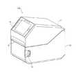
以下、添付図面を参照しながら本発明の実施形態に係るプリンタ100について説明する。図1は、本発明の実施形態に係るプリンタの斜視図である。また、図2は、本発明の実施形態に係るプリンタの概略構成図である。[Overview of the printer]
Hereinafter, the
プリンタ100は、例えば、インクリボンRを熱してインクリボンRのインクを印字媒体Mに転写することで印字を行う熱転写方式の印字装置である。 The
印字媒体Mは、例えば、帯状の台紙に複数のラベルが連続して仮着されたラベル連続体である。また、印字媒体Mとして、台紙なしラベルやファンフォールド型媒体を使用することもできる。 The printing medium M is, for example, a label continuum in which a plurality of labels are continuously temporarily attached to a strip-shaped mount. Further, as the print medium M, a label without a mount or a fan-fold type medium can also be used.
印字媒体Mは、図2に示すように、中心が空洞でロール状に巻き回された状態で、空洞部分を媒体供給軸12により保持される。 As shown in FIG. 2, the print medium M is held by the
プリンタ100は、図1、図2に示すように、下側筐体10と、下側筐体10の開口部を覆う上側筐体11と、を備える。 As shown in FIGS. 1 and 2, the
下側筐体10は、開口部を有する筐体であり、印字媒体Mに印字を行うための印字ユニット30、プリンタ100の動作を制御するコントローラ40等を収容する(各構成の詳細は後述する)。 The
上側筐体11は、下側筐体10に対して、下側筐体10の開口部を開閉可能に取り付けられており、下側筐体10に収容されて一部が開口部から露呈した印字ユニット30、コントローラ40等の構成を覆っている。 The
また、プリンタ100は、例えば、図2に示すように、通信装置が接続される接続部111と、通信装置が接続された状態で接続部111を収容することが可能な収容部112と、収容部112を開閉可能に覆う蓋部113と、を備える。 Further, the
本実施形態において、通信装置は、移動体通信網を介してプリンタと外部装置との通信を可能にする。通信装置は、例えば、SIM(Subscliber Identification Module)規格に準拠したSIMカードが挙げられる。接続部111及び通信装置についての詳細は後述する。 In the present embodiment, the communication device enables communication between the printer and the external device via the mobile communication network. Examples of the communication device include a SIM card compliant with the SIM (Subscriber Identification Module) standard. Details of the
収容部112は、プリンタ100の上側筐体11の内側から開口するように形成されている。接続部111は、蓋部113に配置されている。接続部111、収容部112及び蓋部113の詳細は後述する。 The
上側筐体11は、下側筐体10に設けられた支持軸13により一端側の端部が回動自在に支持される。上側筐体11は、支持軸13を支点として回動させることで、下側筐体10の開口部を開放する開放状態と、閉止する閉止状態と、を切り替えることができる。 The
下側筐体10には、上側筐体11を閉止状態に維持するロック機構(図示せず)が設けられている。ロック機構は、図1に示すレバー14を利用者が操作することで解除される。ロック機能が解除された状態で、利用者が上側筐体11を持ち上げることで、下側筐体10の開口部を開放状態にすることができる。 The
プリンタ100は、上側筐体11の他端側の端部と下側筐体10との間に、図2に示す印字部15で印字された印字媒体Mがプリンタ100から排出される排出口16を備える。 In the
また、上側筐体11の排出口16側には、印字媒体Mを排出口16付近で切断するカッタ17が設けられている。 Further, a
排出口16と印字部15との間には、印字媒体Mの有無を検出するための光学センサとして、例えば、透過センサ18が設けられている。透過センサ18は、発光部18aと受光部18bとから構成されている。 For example, a
また、上側筐体11には、プリンタ100を操作するための操作ユニット19が設けられている。操作ユニット19は、各種操作ボタン、ディスプレイ、近距離無線通信モジュール、LED等を備える。ディスプレイは、タッチパネルであってもよい。 Further, the
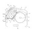
プリンタ100の下側筐体10及び上側筐体11によって形成される空間には、印字媒体Mに印字を行うための印字ユニット30、プリンタ100の動作を制御するコントローラ40等が収容される。 The space formed by the
印字ユニット30は、一端側が支持軸13に揺動自在に支持される本体部31と、本体部31に取り付けられるサーマルヘッド32と、を備える。 The
サーマルヘッド32は、下側筐体10側に設けられたプラテンローラ20と共に、印字媒体Mに印字を行う印字部15を構成している。 The
また、印字ユニット30は、リボン供給軸33と、リボン巻取軸34と、仕切部材35と、ガイド軸36、37と、を備える。リボン供給軸33は、印字部15に供給されるインクリボンRをロール状に保持する。また、リボン供給軸33は、仕切部材35に着脱可能に取り付けられる。リボン巻取軸34は、使用済のインクリボンRを巻き取る。仕切部材35は、インクリボンRと印字媒体Mとの間を仕切る。ガイド軸36は、リボン供給軸33から印字部15へのインクリボンRの搬送路を規定する。ガイド軸37は、印字部15からリボン巻取軸34へのインクリボンRの搬送路を規定する。 Further, the
印字媒体Mは、ロール状に巻きまわされた状態から印字部15に供給され、サーマルヘッド32とプラテンローラ20との間にインクリボンRと共に挟持される。 The print medium M is supplied to the
印字媒体M及びインクリボンRがサーマルヘッド32とプラテンローラ20との間に挟持された状態でサーマルヘッド32の発熱素子への通電が行われると、印字ユニット30は、発熱素子の熱によってインクリボンRのインクを印字媒体Mに転写し、印字媒体Mへの印字を行う。 When the heat generating element of the
また、プラテン駆動モータ(図示せず)によってプラテンローラ20を正回転させると、印字媒体M及びインクリボンRが搬送方向下流側へと搬送されて、印字された印字媒体Mは、排出口16からプリンタ100の外部に排出される。 When the
また、図2に示すように、プリンタ100は、反射センサ21を備える。反射センサ21は、印字媒体Mの印字が施される面とは反対側の面に所定の間隔で予め印刷されているアイマークを検出するセンサである。これにより、印字媒体Mの搬送方向における位置を検出することができる。 Further, as shown in FIG. 2, the
仕切部材35は、図2に示すように、ベース部35aと、ベース部35aの一端側に設けられた軸部35bと、リボン供給軸33を軸部35bと平行且つ回動自在に支持する支持部35cと、軸部35bの中央部に形成された係合部35dと、を備える。 As shown in FIG. 2, the
仕切部材35は、軸部35bにより本体部31に揺動自在に支持される。 The
係合部35dは、図2に示すように、上側筐体11に設けられた被係合部11aと係合するように構成されている。仕切部材35を係合部35dが被係合部11aと係合する位置(閉止位置)にすると、リボン供給軸33が本体部31内に収容される。これにより、リボン供給軸33が、印字部15にインクリボンRを供給するリボン供給位置になる。 As shown in FIG. 2, the engaging
プリンタ100による印字を行う際は、上側筐体11は、仕切部材35の係合部35dが上側筐体11の被係合部11aと係合した閉止状態になる。 When printing is performed by the
また、閉止状態の上側筐体11を印字ユニット30と一体となって揺動させると、下側筐体10の開口部が開放する開放状態になる。これにより、プリンタ100への印字媒体Mのセットや下側筐体10内の各部のメンテナンスを行うことができる。 Further, when the
[収容部周囲の説明]
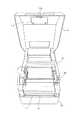
次に、上側筐体11における収容部112について説明する。図3は、本発明の実施形態に係るプリンタ100の上側筐体11を開放した状態を説明する模式図である。図4は、本発明の実施形態に係るプリンタ100の上側筐体11を開放した状態の正面図である。また、図5は、本発明の実施形態に係るプリンタ100の上側筐体11を開放した状態で蓋部を開放した状態を説明する模式図である。[Explanation around the housing]
Next, the
図3に示すように、本実施形態に係るプリンタ100は、上側筐体11の内側に接続部111、収容部112及び蓋部113を備える。 As shown in FIG. 3, the
収容部112は、上側筐体11の内側に形成されている。本実施形態に係るプリンタ100においては、操作ユニット19の背面側且つ上側筐体11の内側に収容部112が形成されている。 The
収容部112は、接続部111及び接続部111に接続された通信装置を収容可能なサイズの空間が形成されている。収容部112の開口部分は、蓋部113によって覆うことができる。蓋部113は、上側筐体11の内側表面を構成している。収容部112を覆う蓋部113は、プリンタ100の内側に向けて開放するように形成されている。プリンタ100の内側に向けるとは、例えば、プリンタ100の上側筐体11が開放状態であって、上側筐体11から下側筐体10側に蓋部113を向けることである。 The
蓋部113は、回動軸114を介して、図3及び図5に示す回動方向D1に、上側筐体11の内側に対して回動可能である。これにより、蓋部113は、収容部112を閉鎖する閉鎖状態(図4に示す)と、収容部112を開放する開放状態(図5に示す)とを取り得る。 The
蓋部113は、必要に応じて開放されるとき以外は、図4に示すように、係止爪115によって、上側筐体11の内側に係止可能である。必要に応じてとは、例えば、接続部111に通信装置を着脱させる場合や他の通信装置と交換する場合等である。なお、蓋部113は、簡単に開放されて収容された通信装置を簡単に持ち出し、盗難等されないように、係止爪115以外に螺旋等で固定されていてもよい。 As shown in FIG. 4, the
続いて、接続部111について説明する。図5に示すように、本実施形態においては、接続部111は、蓋部113に配置されている。 Subsequently, the
本実施形態において、接続部111は、図5に示すように、USB(Universal Serial Bus)規格に準拠した接続端子(以下、USBポートと記す)111a,111bとを備える。 In the present embodiment, as shown in FIG. 5, the
また、本実施形態に係るプリンタ100は、USBポート111aに、変換アダプタ150を介してSIMカード160が装着される。 Further, in the
変換アダプタ150は、一方がUSBポート111aと電気的に接続可能に構成され、他方がSIMカード160と電気的に接続可能に構成されたものであり、SIM規格に準拠したSIMカード160を装着可能とされている。変換アダプタ150は、例えば、USBドングルである。なお、図5において、SIMカード160は、可視的に図示されているが、実際には、変換アダプタ150の内部に装着することができる。 One of the
SIMカード160は、特定の通信サービスを提供する通信業者によって発行されたモジュールであり、対応した通信機器に装着されることによって、無線通信サービスが利用可能となる。SIMカードには、無線通信サービスを利用する際に必要となる顧客識別番号、通信端末を特定するための端末固有番号等が格納されている。 The
プリンタ100は、図示しないが、SIMカード160を少なくとも読み取り可能とする構成を備える。 Although not shown, the
本実施形態においては、プリンタ100は、変換アダプタ150を介してSIMカード160が装着されることにより、上記通信業者によって提供される無線通信回線に接続可能となる。 In the present embodiment, the
図6は、接続部111の別の実施形態を説明する模式図である。本実施形態において、接続部111は、図6に示すように、USB規格に準拠したUSBポート111a,111bに加えて、SIMカードスロット111cを備える。 FIG. 6 is a schematic diagram illustrating another embodiment of the
SIMカードスロット111cは、SIM規格に準拠したSIMカードの装着部である。 The
本実施形態においては、SIMカードスロット111cにSIMカードが装着されることにより、プリンタ100は、上記通信業者によって提供される無線通信回線に接続可能となる。 In the present embodiment, by installing the SIM card in the
なお、図6の例において、プリンタ100は、USBポート111a,111b及びSIMカードスロット111cのそれぞれを備えた例を示しているが、USBポート111a,111bを備えていなくてもよい。 In the example of FIG. 6, the
[効果]
本発明の実施形態に係るプリンタ100は、接続部111としてのUSBポート111a,111bと、USBポート111a,111bが収められる収容部112と、収容部112を開閉可能に覆う蓋部113とを、プリンタ100の上側筐体11の内側に備える。USBポート111a,111bは、蓋部113に配置されている。[effect]
In the
プリンタ100は、接続部111に接続された状態の通信装置を上側筐体11に形成された収容部112に収めることができる。つまり、本発明の実施形態によれば、プリンタ100の筐体内部にSIMモジュールを収納することができるため、SIMモジュールを用いてプリンタ100から移動体通信網を介して外部装置と直接通信することが可能となる。 The
また、接続部111が収容部112に収容されることにより、接続部111に接続された通信装置に利用者が触れたり、プリンタ100の動作中に物が当たったりすることがないため、通信装置との間のデータ送受が安定して行われる。 Further, since the
プリンタ100において、接続部111は、上側筐体11の内側に設けられた収容部112に配置されている。すなわち、接続部111に接続された通信装置は、プリンタ100の外側からみえない位置に配置することができる。 In the
このため、例えば、通信装置の着脱を許可されていない者が、通信装置を接続部111から不要に抜き取ったり、プリンタ100において使用されるデータを改ざんしたり、プリンタ100の正常動作を妨げるようなプログラムを読み込ませたりする行為を防止することができる。 Therefore, for example, a person who is not permitted to attach / detach the communication device may unnecessarily remove the communication device from the
接続部111は、上側筐体11の内側に設けられた収容部112を覆う蓋部113に配置されている。例えば、収容部112の内部に接続部111を設けた場合には、利用者が、USBポート111a,111b或いはSIMカードスロット111cから通信装置を着脱するためのスペースを確保する必要がある。 The connecting
これに対して、接続部111が蓋部113に配置されている場合には、図5に示すように、USBポート111a、111bに通信装置を挿入して取り付けたり取り外したり、装着したりするための抜差方向D2が開放されている。このため、利用者は、通信装置の着脱操作を行い易くなる。 On the other hand, when the
また、収容部112に通信装置を着脱するためのスペースを考慮すること無く、少なくとも通信装置を収容可能なサイズに設計すればよいため、プリンタ100の小型化に寄与できる。 Further, since it is sufficient to design the printer to have a size that can accommodate at least the communication device without considering the space for attaching and detaching the communication device to the
また、プリンタ100は、接続部111としてSIMカードスロット111cを備える。これにより、プリンタ100は、ユーザ等によって用意されたローカルネットワークを経由することなく、プリンタ100単独で、いわゆるインターネット等の外部ネットワークに無線接続可能となる。 Further, the
プリンタ100は、SIMカードスロット111cにSIMカードを挿入されると、SIMカードの情報を読み取り、読み取った情報に基づいて、移動体通信網による無線通信サービスが利用可能となる。これにより、プリンタ100は、例えばクラウド等の外部ネットワークに接続することが可能となる。 When the SIM card is inserted into the
一例として、セキュリティ対策等から、プリンタ100のユーザ等によって用意されたローカルネットワークへの接続が制限されている場合がある。この場合であっても、ローカルネットワークのセキュリティ等の設定を変更することなく、プリンタ100は単独でインターネットに接続することができる。 As an example, the connection to the local network prepared by the user of the
したがって、プリンタ100のメンテナンス等を提供する業者は、プリンタ100の使用状態や不具合情報等をプリンタ100から直接取得することができる。 Therefore, a company that provides maintenance and the like of the
[その他の実施形態]
本実施形態において、蓋部113における接続部111の配置位置は、図5に示した例に限定されない。収容部112に収容可能であって、ユーザによる着脱に支障の無い位置であれば、配置可能である。[Other embodiments]
In the present embodiment, the arrangement position of the
本実施形態では、通信装置の接続部111として、USBポート111a,111b及びSIMカードスロット111c以外に、パラレルポート、シリアルポート、PS/2ポート等を備えていてもよい。 In the present embodiment, the
また、SIMカードスロット111cとしては、いわゆるフルサイズSIMのほか、マイクロSIM、ナノSIM等に対応したスロットであってもよい。 Further, the
USBポート111a,111bを利用して、接続可能なデバイスとしては、ブルートゥース通信を可能とするブルートゥース−USBアダプタ、無線LAN(Local Area Network)通信を可能とする無線LAN−USBアダプタ等が挙げられる。 Examples of devices that can be connected using the
10 下側筐体
11 上側筐体
11a 被係合部
12 媒体供給軸
13 支持軸
14 レバー
15 印字部
16 排出口
17 カッタ
18 透過センサ
18a 発光部
18b 受光部
19 操作ユニット
20 プラテンローラ
21 反射センサ
30 印字ユニット
31 本体部
32 サーマルヘッド
33 リボン供給軸
34 リボン巻取軸
35 仕切部材
35a ベース部
35b 軸部
35c 支持部
35d 係合部
36 ガイド軸
37 ガイド軸
40 コントローラ
100 プリンタ
111 接続部
111a USBポート
111c SIMカードスロット
112 収容部
113 蓋部
114 回動軸
115 係止爪
150 変換アダプタ
160 SIMカード
D1 回動方向
D2 抜差方向10
Claims (5)
Translated fromJapanese下側筐体と、
前記下側筐体に対して開閉可能に取り付けられた上側筐体と、を備え、
前記上側筐体の内側に、
移動体通信網を介して外部装置と通信する通信装置が接続される接続部と、
前記接続部が収容可能な収容部と、
前記収容部を開閉可能に覆う蓋部と、
を有し、
前記接続部が前記蓋部に配置された、
プリンタ。A printer that prints on roll-shaped print media.
With the lower housing
The upper housing, which is attached to the lower housing so as to be openable and closable, is provided.
Inside the upper housing,
A connection part to which a communication device that communicates with an external device is connected via a mobile communication network,
And the housing portion capable of housing theprevious Symbol connection part,
A lid that can be opened and closed, and a lid that can be opened and closed.
Have a,
The connection portion is arranged on the lid portion,
Printer.
前記収容部は、前記プリンタの内側から開口するように形成された、
プリンタ。The printer according to claim 1.
The accommodating portion is formed so as to open from the inside of the printer.
Printer.
前記接続部は、USBポートである、
プリンタ。The printer according to claim 1or 2.
The connection is a USB port.
Printer.
前記USBポートには、変換アダプタを介してSIMカードが装着される、
プリンタ。The printer according to claim3.
A SIM card is attached to the USB port via a conversion adapter.
Printer.
前記接続部は、SIMカードスロットである、
プリンタ。The printer according to claim 1or 2.
The connection is a SIM card slot.
Printer.
Priority Applications (2)
| Application Number | Priority Date | Filing Date | Title |
|---|---|---|---|
| JP2017185379AJP6981829B2 (en) | 2017-09-26 | 2017-09-26 | Printer |
| JP2020157325AJP6982153B2 (en) | 2017-09-26 | 2020-09-18 | Printer |
Applications Claiming Priority (1)
| Application Number | Priority Date | Filing Date | Title |
|---|---|---|---|
| JP2017185379AJP6981829B2 (en) | 2017-09-26 | 2017-09-26 | Printer |
Related Child Applications (1)
| Application Number | Title | Priority Date | Filing Date |
|---|---|---|---|
| JP2020157325ADivisionJP6982153B2 (en) | 2017-09-26 | 2020-09-18 | Printer |
Publications (2)
| Publication Number | Publication Date |
|---|---|
| JP2019059111A JP2019059111A (en) | 2019-04-18 |
| JP6981829B2true JP6981829B2 (en) | 2021-12-17 |
Family
ID=66176975
Family Applications (1)
| Application Number | Title | Priority Date | Filing Date |
|---|---|---|---|
| JP2017185379AActiveJP6981829B2 (en) | 2017-09-26 | 2017-09-26 | Printer |
Country Status (1)
| Country | Link |
|---|---|
| JP (1) | JP6981829B2 (en) |
Families Citing this family (2)
| Publication number | Priority date | Publication date | Assignee | Title |
|---|---|---|---|---|
| JP7468195B2 (en) | 2020-06-30 | 2024-04-16 | セイコーエプソン株式会社 | Printing device |
| US20220223997A1 (en)* | 2021-01-13 | 2022-07-14 | Zebra Technologies Corporation | User-Installable Wireless Communications Module |
Family Cites Families (8)
| Publication number | Priority date | Publication date | Assignee | Title |
|---|---|---|---|---|
| AUPS049102A0 (en)* | 2002-02-13 | 2002-03-07 | Silverbrook Research Pty. Ltd. | Methods and systems (ap51) |
| JP4633017B2 (en)* | 2006-07-19 | 2011-02-16 | シャープ株式会社 | Document reading apparatus and image forming apparatus |
| JP2008168590A (en)* | 2007-01-15 | 2008-07-24 | Seiko Epson Corp | Electronics |
| US20090009937A1 (en)* | 2007-07-05 | 2009-01-08 | Jones Brenda S | Electronic devices with storage compartments for memory devices |
| JP5260031B2 (en)* | 2007-11-20 | 2013-08-14 | 株式会社スマート | Wireless transmission / reception device, non-contact information recording medium, information reading / writing device, and management system |
| CN202210818U (en)* | 2011-09-22 | 2012-05-02 | 吴福兴 | Mobile phone provided with multifunctional accessory |
| JP2013219711A (en)* | 2012-04-12 | 2013-10-24 | Sharp Corp | Recording medium connection device, image formation apparatus including the same, and information processing apparatus including the same |
| JP6269124B2 (en)* | 2014-02-06 | 2018-01-31 | 株式会社リコー | Device management system, information processing apparatus, device management method, and program |
- 2017
- 2017-09-26JPJP2017185379Apatent/JP6981829B2/enactiveActive
Also Published As
| Publication number | Publication date |
|---|---|
| JP2019059111A (en) | 2019-04-18 |
Similar Documents
| Publication | Publication Date | Title |
|---|---|---|
| EP3075557B1 (en) | Print device | |
| US9246341B2 (en) | Mobile printer networking and interfacing | |
| KR100927986B1 (en) | Pocket thermal printer for printing labels | |
| JP5432050B2 (en) | Portable printer | |
| CN101168328B (en) | printer unit | |
| US7909522B2 (en) | Portable printer with adjustable media tray | |
| US7896564B2 (en) | Portable printer | |
| JP6981829B2 (en) | Printer | |
| JP2008062597A (en) | Printer | |
| JP6731472B2 (en) | Printer | |
| JP4918326B2 (en) | Printer | |
| EP1512543A1 (en) | Printer and method of printing | |
| JP6982153B2 (en) | Printer | |
| JP2007261771A (en) | Printer equipped with detachable recording paper storage device | |
| JP7057367B2 (en) | Printer | |
| RU2001116120A (en) | DIGITAL CAMERA DEVICE WITH INTEGRATED PRINTER | |
| JP2023092586A (en) | Printing device | |
| JP2024000023A (en) | Ink ribbon cassette and printing device | |
| CN116507502A (en) | Printer with a printer body | |
| KR20200106668A (en) | Portable Printer | |
| JP2019059109A (en) | Printer | |
| JP2019059110A (en) | Printer | |
| JP2006052081A (en) | Printer | |
| JP2007253630A (en) | Portable printer device | |
| JP2004059284A (en) | Recording medium holder and recording device |
Legal Events
| Date | Code | Title | Description |
|---|---|---|---|
| RD02 | Notification of acceptance of power of attorney | Free format text:JAPANESE INTERMEDIATE CODE: A7422 Effective date:20200305 | |
| A621 | Written request for application examination | Free format text:JAPANESE INTERMEDIATE CODE: A621 Effective date:20200813 | |
| A977 | Report on retrieval | Free format text:JAPANESE INTERMEDIATE CODE: A971007 Effective date:20210322 | |
| A131 | Notification of reasons for refusal | Free format text:JAPANESE INTERMEDIATE CODE: A131 Effective date:20210406 | |
| A521 | Request for written amendment filed | Free format text:JAPANESE INTERMEDIATE CODE: A523 Effective date:20210602 | |
| A131 | Notification of reasons for refusal | Free format text:JAPANESE INTERMEDIATE CODE: A131 Effective date:20210713 | |
| A521 | Request for written amendment filed | Free format text:JAPANESE INTERMEDIATE CODE: A523 Effective date:20210906 | |
| TRDD | Decision of grant or rejection written | ||
| A01 | Written decision to grant a patent or to grant a registration (utility model) | Free format text:JAPANESE INTERMEDIATE CODE: A01 Effective date:20211102 | |
| A61 | First payment of annual fees (during grant procedure) | Free format text:JAPANESE INTERMEDIATE CODE: A61 Effective date:20211118 | |
| R150 | Certificate of patent or registration of utility model | Ref document number:6981829 Country of ref document:JP Free format text:JAPANESE INTERMEDIATE CODE: R150 | |
| R250 | Receipt of annual fees | Free format text:JAPANESE INTERMEDIATE CODE: R250 |