JP6981204B2 - vehicle - Google Patents
vehicleDownload PDFInfo
- Publication number
- JP6981204B2 JP6981204B2JP2017225969AJP2017225969AJP6981204B2JP 6981204 B2JP6981204 B2JP 6981204B2JP 2017225969 AJP2017225969 AJP 2017225969AJP 2017225969 AJP2017225969 AJP 2017225969AJP 6981204 B2JP6981204 B2JP 6981204B2
- Authority
- JP
- Japan
- Prior art keywords
- power
- storage device
- soc
- power storage
- solar
- Prior art date
- Legal status (The legal status is an assumption and is not a legal conclusion. Google has not performed a legal analysis and makes no representation as to the accuracy of the status listed.)
- Expired - Fee Related
Links
Images


Classifications
- B—PERFORMING OPERATIONS; TRANSPORTING
- B60—VEHICLES IN GENERAL
- B60L—PROPULSION OF ELECTRICALLY-PROPELLED VEHICLES; SUPPLYING ELECTRIC POWER FOR AUXILIARY EQUIPMENT OF ELECTRICALLY-PROPELLED VEHICLES; ELECTRODYNAMIC BRAKE SYSTEMS FOR VEHICLES IN GENERAL; MAGNETIC SUSPENSION OR LEVITATION FOR VEHICLES; MONITORING OPERATING VARIABLES OF ELECTRICALLY-PROPELLED VEHICLES; ELECTRIC SAFETY DEVICES FOR ELECTRICALLY-PROPELLED VEHICLES
- B60L8/00—Electric propulsion with power supply from forces of nature, e.g. sun or wind
- B60L8/003—Converting light into electric energy, e.g. by using photo-voltaic systems
- B—PERFORMING OPERATIONS; TRANSPORTING
- B60—VEHICLES IN GENERAL
- B60K—ARRANGEMENT OR MOUNTING OF PROPULSION UNITS OR OF TRANSMISSIONS IN VEHICLES; ARRANGEMENT OR MOUNTING OF PLURAL DIVERSE PRIME-MOVERS IN VEHICLES; AUXILIARY DRIVES FOR VEHICLES; INSTRUMENTATION OR DASHBOARDS FOR VEHICLES; ARRANGEMENTS IN CONNECTION WITH COOLING, AIR INTAKE, GAS EXHAUST OR FUEL SUPPLY OF PROPULSION UNITS IN VEHICLES
- B60K35/00—Instruments specially adapted for vehicles; Arrangement of instruments in or on vehicles
- B—PERFORMING OPERATIONS; TRANSPORTING
- B60—VEHICLES IN GENERAL
- B60L—PROPULSION OF ELECTRICALLY-PROPELLED VEHICLES; SUPPLYING ELECTRIC POWER FOR AUXILIARY EQUIPMENT OF ELECTRICALLY-PROPELLED VEHICLES; ELECTRODYNAMIC BRAKE SYSTEMS FOR VEHICLES IN GENERAL; MAGNETIC SUSPENSION OR LEVITATION FOR VEHICLES; MONITORING OPERATING VARIABLES OF ELECTRICALLY-PROPELLED VEHICLES; ELECTRIC SAFETY DEVICES FOR ELECTRICALLY-PROPELLED VEHICLES
- B60L53/00—Methods of charging batteries, specially adapted for electric vehicles; Charging stations or on-board charging equipment therefor; Exchange of energy storage elements in electric vehicles
- B60L53/20—Methods of charging batteries, specially adapted for electric vehicles; Charging stations or on-board charging equipment therefor; Exchange of energy storage elements in electric vehicles characterised by converters located in the vehicle
- B—PERFORMING OPERATIONS; TRANSPORTING
- B60—VEHICLES IN GENERAL
- B60L—PROPULSION OF ELECTRICALLY-PROPELLED VEHICLES; SUPPLYING ELECTRIC POWER FOR AUXILIARY EQUIPMENT OF ELECTRICALLY-PROPELLED VEHICLES; ELECTRODYNAMIC BRAKE SYSTEMS FOR VEHICLES IN GENERAL; MAGNETIC SUSPENSION OR LEVITATION FOR VEHICLES; MONITORING OPERATING VARIABLES OF ELECTRICALLY-PROPELLED VEHICLES; ELECTRIC SAFETY DEVICES FOR ELECTRICALLY-PROPELLED VEHICLES
- B60L53/00—Methods of charging batteries, specially adapted for electric vehicles; Charging stations or on-board charging equipment therefor; Exchange of energy storage elements in electric vehicles
- B60L53/50—Charging stations characterised by energy-storage or power-generation means
- B60L53/51—Photovoltaic means
- B—PERFORMING OPERATIONS; TRANSPORTING
- B60—VEHICLES IN GENERAL
- B60L—PROPULSION OF ELECTRICALLY-PROPELLED VEHICLES; SUPPLYING ELECTRIC POWER FOR AUXILIARY EQUIPMENT OF ELECTRICALLY-PROPELLED VEHICLES; ELECTRODYNAMIC BRAKE SYSTEMS FOR VEHICLES IN GENERAL; MAGNETIC SUSPENSION OR LEVITATION FOR VEHICLES; MONITORING OPERATING VARIABLES OF ELECTRICALLY-PROPELLED VEHICLES; ELECTRIC SAFETY DEVICES FOR ELECTRICALLY-PROPELLED VEHICLES
- B60L58/00—Methods or circuit arrangements for monitoring or controlling batteries or fuel cells, specially adapted for electric vehicles
- B60L58/10—Methods or circuit arrangements for monitoring or controlling batteries or fuel cells, specially adapted for electric vehicles for monitoring or controlling batteries
- B60L58/12—Methods or circuit arrangements for monitoring or controlling batteries or fuel cells, specially adapted for electric vehicles for monitoring or controlling batteries responding to state of charge [SoC]
- H—ELECTRICITY
- H02—GENERATION; CONVERSION OR DISTRIBUTION OF ELECTRIC POWER
- H02J—CIRCUIT ARRANGEMENTS OR SYSTEMS FOR SUPPLYING OR DISTRIBUTING ELECTRIC POWER; SYSTEMS FOR STORING ELECTRIC ENERGY
- H02J7/00—Circuit arrangements for charging or depolarising batteries or for supplying loads from batteries
- H02J7/34—Parallel operation in networks using both storage and other DC sources, e.g. providing buffering
- H02J7/35—Parallel operation in networks using both storage and other DC sources, e.g. providing buffering with light sensitive cells
- B—PERFORMING OPERATIONS; TRANSPORTING
- B60—VEHICLES IN GENERAL
- B60L—PROPULSION OF ELECTRICALLY-PROPELLED VEHICLES; SUPPLYING ELECTRIC POWER FOR AUXILIARY EQUIPMENT OF ELECTRICALLY-PROPELLED VEHICLES; ELECTRODYNAMIC BRAKE SYSTEMS FOR VEHICLES IN GENERAL; MAGNETIC SUSPENSION OR LEVITATION FOR VEHICLES; MONITORING OPERATING VARIABLES OF ELECTRICALLY-PROPELLED VEHICLES; ELECTRIC SAFETY DEVICES FOR ELECTRICALLY-PROPELLED VEHICLES
- B60L2210/00—Converter types
- B60L2210/10—DC to DC converters
- B—PERFORMING OPERATIONS; TRANSPORTING
- B60—VEHICLES IN GENERAL
- B60L—PROPULSION OF ELECTRICALLY-PROPELLED VEHICLES; SUPPLYING ELECTRIC POWER FOR AUXILIARY EQUIPMENT OF ELECTRICALLY-PROPELLED VEHICLES; ELECTRODYNAMIC BRAKE SYSTEMS FOR VEHICLES IN GENERAL; MAGNETIC SUSPENSION OR LEVITATION FOR VEHICLES; MONITORING OPERATING VARIABLES OF ELECTRICALLY-PROPELLED VEHICLES; ELECTRIC SAFETY DEVICES FOR ELECTRICALLY-PROPELLED VEHICLES
- B60L2210/00—Converter types
- B60L2210/30—AC to DC converters
- B—PERFORMING OPERATIONS; TRANSPORTING
- B60—VEHICLES IN GENERAL
- B60L—PROPULSION OF ELECTRICALLY-PROPELLED VEHICLES; SUPPLYING ELECTRIC POWER FOR AUXILIARY EQUIPMENT OF ELECTRICALLY-PROPELLED VEHICLES; ELECTRODYNAMIC BRAKE SYSTEMS FOR VEHICLES IN GENERAL; MAGNETIC SUSPENSION OR LEVITATION FOR VEHICLES; MONITORING OPERATING VARIABLES OF ELECTRICALLY-PROPELLED VEHICLES; ELECTRIC SAFETY DEVICES FOR ELECTRICALLY-PROPELLED VEHICLES
- B60L2210/00—Converter types
- B60L2210/40—DC to AC converters
- B—PERFORMING OPERATIONS; TRANSPORTING
- B60—VEHICLES IN GENERAL
- B60L—PROPULSION OF ELECTRICALLY-PROPELLED VEHICLES; SUPPLYING ELECTRIC POWER FOR AUXILIARY EQUIPMENT OF ELECTRICALLY-PROPELLED VEHICLES; ELECTRODYNAMIC BRAKE SYSTEMS FOR VEHICLES IN GENERAL; MAGNETIC SUSPENSION OR LEVITATION FOR VEHICLES; MONITORING OPERATING VARIABLES OF ELECTRICALLY-PROPELLED VEHICLES; ELECTRIC SAFETY DEVICES FOR ELECTRICALLY-PROPELLED VEHICLES
- B60L2250/00—Driver interactions
- B60L2250/16—Driver interactions by display
- H—ELECTRICITY
- H02—GENERATION; CONVERSION OR DISTRIBUTION OF ELECTRIC POWER
- H02J—CIRCUIT ARRANGEMENTS OR SYSTEMS FOR SUPPLYING OR DISTRIBUTING ELECTRIC POWER; SYSTEMS FOR STORING ELECTRIC ENERGY
- H02J7/00—Circuit arrangements for charging or depolarising batteries or for supplying loads from batteries
- H02J7/0047—Circuit arrangements for charging or depolarising batteries or for supplying loads from batteries with monitoring or indicating devices or circuits
- H02J7/0048—Detection of remaining charge capacity or state of charge [SOC]
- Y—GENERAL TAGGING OF NEW TECHNOLOGICAL DEVELOPMENTS; GENERAL TAGGING OF CROSS-SECTIONAL TECHNOLOGIES SPANNING OVER SEVERAL SECTIONS OF THE IPC; TECHNICAL SUBJECTS COVERED BY FORMER USPC CROSS-REFERENCE ART COLLECTIONS [XRACs] AND DIGESTS
- Y02—TECHNOLOGIES OR APPLICATIONS FOR MITIGATION OR ADAPTATION AGAINST CLIMATE CHANGE
- Y02T—CLIMATE CHANGE MITIGATION TECHNOLOGIES RELATED TO TRANSPORTATION
- Y02T10/00—Road transport of goods or passengers
- Y02T10/60—Other road transportation technologies with climate change mitigation effect
- Y02T10/70—Energy storage systems for electromobility, e.g. batteries
- Y—GENERAL TAGGING OF NEW TECHNOLOGICAL DEVELOPMENTS; GENERAL TAGGING OF CROSS-SECTIONAL TECHNOLOGIES SPANNING OVER SEVERAL SECTIONS OF THE IPC; TECHNICAL SUBJECTS COVERED BY FORMER USPC CROSS-REFERENCE ART COLLECTIONS [XRACs] AND DIGESTS
- Y02—TECHNOLOGIES OR APPLICATIONS FOR MITIGATION OR ADAPTATION AGAINST CLIMATE CHANGE
- Y02T—CLIMATE CHANGE MITIGATION TECHNOLOGIES RELATED TO TRANSPORTATION
- Y02T10/00—Road transport of goods or passengers
- Y02T10/60—Other road transportation technologies with climate change mitigation effect
- Y02T10/7072—Electromobility specific charging systems or methods for batteries, ultracapacitors, supercapacitors or double-layer capacitors
- Y—GENERAL TAGGING OF NEW TECHNOLOGICAL DEVELOPMENTS; GENERAL TAGGING OF CROSS-SECTIONAL TECHNOLOGIES SPANNING OVER SEVERAL SECTIONS OF THE IPC; TECHNICAL SUBJECTS COVERED BY FORMER USPC CROSS-REFERENCE ART COLLECTIONS [XRACs] AND DIGESTS
- Y02—TECHNOLOGIES OR APPLICATIONS FOR MITIGATION OR ADAPTATION AGAINST CLIMATE CHANGE
- Y02T—CLIMATE CHANGE MITIGATION TECHNOLOGIES RELATED TO TRANSPORTATION
- Y02T90/00—Enabling technologies or technologies with a potential or indirect contribution to GHG emissions mitigation
- Y02T90/10—Technologies relating to charging of electric vehicles
- Y02T90/12—Electric charging stations
- Y—GENERAL TAGGING OF NEW TECHNOLOGICAL DEVELOPMENTS; GENERAL TAGGING OF CROSS-SECTIONAL TECHNOLOGIES SPANNING OVER SEVERAL SECTIONS OF THE IPC; TECHNICAL SUBJECTS COVERED BY FORMER USPC CROSS-REFERENCE ART COLLECTIONS [XRACs] AND DIGESTS
- Y02—TECHNOLOGIES OR APPLICATIONS FOR MITIGATION OR ADAPTATION AGAINST CLIMATE CHANGE
- Y02T—CLIMATE CHANGE MITIGATION TECHNOLOGIES RELATED TO TRANSPORTATION
- Y02T90/00—Enabling technologies or technologies with a potential or indirect contribution to GHG emissions mitigation
- Y02T90/10—Technologies relating to charging of electric vehicles
- Y02T90/14—Plug-in electric vehicles
Landscapes
- Engineering & Computer Science (AREA)
- Power Engineering (AREA)
- Transportation (AREA)
- Mechanical Engineering (AREA)
- Life Sciences & Earth Sciences (AREA)
- Sustainable Development (AREA)
- Sustainable Energy (AREA)
- Combustion & Propulsion (AREA)
- Chemical & Material Sciences (AREA)
- Charge And Discharge Circuits For Batteries Or The Like (AREA)
- Hybrid Electric Vehicles (AREA)
- Remote Monitoring And Control Of Power-Distribution Networks (AREA)
- Supply And Distribution Of Alternating Current (AREA)
- Electric Propulsion And Braking For Vehicles (AREA)
Description
Translated fromJapanese本開示は、外部の電力設備から供給される電力で充電可能に構成された蓄電装置を備える車両に関する。 The present disclosure relates to a vehicle including a power storage device configured to be rechargeable with electric power supplied from an external electric power facility.
近年、外部の電力設備から供給される電力で充電可能に構成された蓄電装置を備える、いわゆるプラグインタイプの電動車両(プラグインハイブリッド自動車、電気自動車など)が急速に普及しつつある。 In recent years, so-called plug-in type electric vehicles (plug-in hybrid vehicles, electric vehicles, etc.) equipped with a power storage device configured to be rechargeable with electric power supplied from an external electric power facility are rapidly becoming widespread.
電力設備から車両に供給される電力には、異なる発電方法によって得られた電力、たとえば、二酸化炭素などの温室効果ガスの排出量の極めて少ない太陽光発電あるいは風力発電等によって発電された電力(以下「グリーン電力」ともいう)と、温室効果ガスの排出量の多い火力発電等によって発電された電力(以下「非グリーン電力」ともいう)とが混在し得る。 The power supplied to the vehicle from the power equipment includes power obtained by different power generation methods, for example, power generated by solar power generation or wind power generation, which emits extremely little greenhouse gas such as carbon dioxide (hereinafter referred to as power generation). "Green power") and power generated by thermal power generation, etc., which emits a large amount of greenhouse gas (hereinafter, also referred to as "non-green power") can coexist.
地球温暖化を防止して地球環境を保全する意識の高いユーザにおいては、自身が利用する車両の蓄電装置をグリーン電力で充電することを望む傾向にある。このようなユーザのニーズを考慮した車両が、たとえば特開2013−24680号公報(特許文献1)に開示されている。この車両は、グリーン電力で走行可能な距離と、非グリーン電力で走行可能な距離とを、自車を中心とするリング状にそれぞれ表示するナビゲーション装置を備えている。 Users who are highly conscious of preventing global warming and preserving the global environment tend to desire to charge the power storage device of their vehicle with green power. A vehicle in consideration of such user needs is disclosed in, for example, Japanese Patent Application Laid-Open No. 2013-24680 (Patent Document 1). This vehicle is equipped with a navigation device that displays the distance that can be traveled by green power and the distance that can be traveled by non-green power in a ring shape centered on the own vehicle.
特許文献1に開示された車両においては、グリーン電力で走行可能な距離がナビゲーション装置に表示される。しかしながら、車両が走行可能な距離は、地形や車速、渋滞状況等により変化し得る。そのため、車両の蓄電装置にグリーン電力がどの程度蓄えられているのかをユーザが直観し難いという課題があった。 In the vehicle disclosed in
本開示は、上述の課題を解決するためになされたものであって、その目的は、車両の蓄電装置に蓄えられている電力の由来を車両のユーザが視覚的に認識し易くすることである。 The present disclosure has been made to solve the above-mentioned problems, and an object thereof is to make it easier for a vehicle user to visually recognize the origin of the electric power stored in the power storage device of the vehicle. ..
(1) 本開示による車両は、外部の電力設備から供給される電力で充電可能に構成された蓄電装置と、蓄電装置のSOCを蓄電装置に蓄えられる電力の由来毎に区別して表示するように構成された表示装置とを備える。 (1) The vehicle according to the present disclosure shall display the storage device configured to be rechargeable by the power supplied from the external power equipment and the SOC of the power storage device separately according to the origin of the power stored in the power storage device. It includes a configured display device.
上記車両によれば、蓄電装置のSOCが、蓄電装置に蓄えられる電力の由来毎に区別して表示装置に表示される。これにより、ユーザは、表示装置を見ることによって、車両の蓄電装置に蓄えられている電力の由来を視覚的に認識することができる。 According to the vehicle, the SOC of the power storage device is displayed on the display device separately for each origin of the electric power stored in the power storage device. As a result, the user can visually recognize the origin of the electric power stored in the power storage device of the vehicle by looking at the display device.
(2) ある形態においては、表示装置は、太陽光を用いて発電された第1電力を由来とする第1SOC領域と、系統電源から供給された第2電力を由来とする第2SOC領域とを区別して表示する。車両は、表示装置に表示される第1SOC領域の大きさおよび第2SOC領域の大きさを制御可能に構成された制御装置をさらに備える。 (2) In a certain form, the display device has a first SOC region derived from the first electric power generated by using sunlight and a second SOC region derived from the second electric power supplied from the grid power supply. Display separately. The vehicle further includes a control device configured to be able to control the size of the first SOC region and the size of the second SOC region displayed on the display device.
上記形態によれば、太陽光を用いて発電された第1電力を由来とする第1SOC領域の大きさ、および系統電源から供給された第2電力を由来とする第2SOC領域の大きさが、制御装置によって制御される。これにより、ユーザは、表示装置に表示される第1SOC領域の大きさと第2SOC領域の大きさとを確認することによって、太陽光を用いて発電された第1電力と系統電源から供給された第2電力とが蓄電装置にどの程度蓄えられているのかを把握することができる。 According to the above embodiment, the size of the first SOC region derived from the first electric power generated by using sunlight and the size of the second SOC region derived from the second electric power supplied from the grid power supply are determined. It is controlled by a control device. As a result, the user confirms the size of the first SOC region and the size of the second SOC region displayed on the display device, so that the first power generated by using sunlight and the second power supplied from the grid power supply can be used. It is possible to grasp how much electric power is stored in the power storage device.
(3) ある形態においては、制御装置は、第2電力よりも第1電力を優先して消費しているように表示する第1表示モードをユーザが選択している場合、蓄電装置の放電に応じて、第2SOC領域の大きさを維持しつつ第1SOC領域の大きさを減少させる。 (3) In a certain form, when the user selects the first display mode in which the control device displays that the first power is consumed in preference to the second power, the power storage device is discharged. Accordingly, the size of the first SOC region is reduced while maintaining the size of the second SOC region.
上記形態によれば、第1表示モード中において、第2SOC領域の大きさは維持されるが、第1SOC領域の大きさは減少される。このような表示により、系統電源から供給された第2電力よりも太陽光を用いて発電された第1電力を優先的に消費しているかような感覚をユーザに抱かせることができる。 According to the above embodiment, in the first display mode, the size of the second SOC region is maintained, but the size of the first SOC region is reduced. With such a display, it is possible to give the user the feeling that the first electric power generated by using sunlight is preferentially consumed over the second electric power supplied from the system power supply.
(4) ある形態においては、制御装置は、第1表示モードをユーザが選択している場合に、蓄電装置の放電量に応じて第1SOC領域の大きさを減少させたことによって第1SOC領域が表示されなくなったときは、蓄電装置の放電量に応じて第2SOC領域の大きさを減少させる。 (4) In a certain form, when the user selects the first display mode, the control device reduces the size of the first SOC region according to the discharge amount of the power storage device, so that the first SOC region is increased. When it disappears, the size of the second SOC region is reduced according to the discharge amount of the power storage device.
上記形態によれば、第1表示モード中において、太陽光を用いて発電された第1電力を優先的に消費し終えた後に、系統電源から供給された第2電力を消費しているかのような感覚をユーザに抱かせることができる。 According to the above embodiment, it is as if the second electric power supplied from the grid power source is consumed after the first electric power generated by using sunlight is preferentially consumed in the first display mode. It is possible to give the user a good feeling.
(5) ある形態においては、制御装置は、第1電力よりも第2電力を優先して消費しているように表示する第2表示モードをユーザが選択している場合、蓄電装置の放電に応じて、第1SOC領域の大きさを維持しつつ第2SOC領域の大きさを減少させる。 (5) In a certain form, when the user selects a second display mode in which the control device displays that the second power is consumed in preference to the first power, the control device discharges the power storage device. Accordingly, the size of the second SOC region is reduced while maintaining the size of the first SOC region.
上記形態によれば、第2表示モード中において、第2SOC領域の大きさが減少されるが、第1SOC領域の大きさは維持される。このような表示により、系統電源から供給された第2電力を優先的に消費しているかような感覚をユーザに抱かせることができる。 According to the above embodiment, in the second display mode, the size of the second SOC region is reduced, but the size of the first SOC region is maintained. With such a display, it is possible to give the user the feeling that the second power supplied from the system power supply is preferentially consumed.
(6) ある形態においては、制御装置は、優先して消費しているように表示する電力を指定しない第3表示モードをユーザが選択している場合、蓄電装置の放電に応じて、第1SOC領域の大きさと第2SOC領域の大きさとの比率を維持しつつ、第1SOC領域の大きさおよび第2SOC領域の大きさを減少させる。 (6) In a certain embodiment, when the user selects a third display mode in which the power to be displayed as preferentially consumed is not specified, the control device responds to the discharge of the power storage device by the first SOC. The size of the first SOC region and the size of the second SOC region are reduced while maintaining the ratio between the size of the region and the size of the second SOC region.
上記形態によれば、第3表示モード中において、蓄電装置に蓄えられている電力を使い切る直前まで第1SOC領域が表示される。このような表示により、蓄電装置に蓄えられている電力を使い切る直前まで、太陽光を用いて発電された第1電力が蓄電装置に充電されたことをユーザに認識させることができる。 According to the above embodiment, in the third display mode, the first SOC area is displayed until immediately before the electric power stored in the power storage device is used up. With such a display, it is possible to make the user recognize that the first electric power generated by using sunlight has been charged in the electric storage device until just before the electric power stored in the electric power storage device is used up.
(7) ある形態においては、電力設備には、太陽光発電装置が備えられる。車両は、電力設備から蓄電装置に供給される電力を調整可能に構成された電力変換器をさらに備える。制御装置は、電力設備から供給される電力で蓄電装置が充電される際に、太陽光発電装置の発電電力に応じて蓄電装置の充電電力が変更されるように電力変換器を制御する。 (7) In a certain form, the electric power equipment is provided with a photovoltaic power generation device. The vehicle is further equipped with a power converter configured to be able to adjust the power supplied from the power equipment to the power storage device. The control device controls the power converter so that when the power storage device is charged with the power supplied from the power equipment, the charging power of the power storage device is changed according to the generated power of the photovoltaic power generation device.
上記形態によれば、太陽光発電装置の発電電力が増加したことに応じて蓄電装置の充電電力を大きくしたり、太陽光発電装置の発電電力が減少したことに応じて蓄電装置の充電電力を小さくしたりすることができる。そのため、太陽光発電装置の発電電力をより多く蓄電装置に取り込むことが可能となる。 According to the above embodiment, the charging power of the power storage device is increased according to the increase in the generated power of the solar power generation device, and the charging power of the power storage device is increased according to the decrease of the generated power of the solar power generation device. It can be made smaller. Therefore, it is possible to take in more power generated by the photovoltaic power generation device into the power storage device.
(8) ある形態においては、制御装置は、電力設備から供給される電力で蓄電装置が充電される際に、第2電力よりも第1電力を優先して充電する第1充電モードをユーザが選択していることを条件として、太陽光発電装置の発電電力に応じて蓄電装置の充電電力が変更されるように電力変換器を制御する。 (8) In a certain form, when the power storage device is charged by the electric power supplied from the electric power equipment, the user sets the first charging mode in which the first electric power is given priority over the second electric power. On condition that it is selected, the power converter is controlled so that the charging power of the power storage device is changed according to the generated power of the solar power generation device.
上記形態によれば、ユーザの要求に応じて、太陽光発電装置の発電電力をより多く蓄電装置に取り込むことが可能となる。 According to the above embodiment, it is possible to take in more power generated by the photovoltaic power generation device into the power storage device according to the user's request.
本開示によれば、車両の蓄電装置に蓄えられている電力の由来を車両のユーザが視覚的に認識し易くすることができる。 According to the present disclosure, it is possible to make it easier for the user of the vehicle to visually recognize the origin of the electric power stored in the power storage device of the vehicle.
以下、本実施の形態について、図面を参照しながら詳細に説明する。なお、図中同一または相当部分には同一符号を付してその説明は繰り返さない。 Hereinafter, the present embodiment will be described in detail with reference to the drawings. The same or corresponding parts in the drawings are designated by the same reference numerals and the description thereof will not be repeated.
本開示において「電力」という用語は、狭義の電力(仕事率)を意味する場合と、広義の電力である電力量(仕事量)または電気エネルギを意味する場合とがあり、その用語が使用される状況に応じて弾力的に解釈される。 In the present disclosure, the term "electric power" may mean electric power in a narrow sense (power) or electric energy (power) or electric energy in a broad sense, and the term is used. It is interpreted flexibly according to the situation.
[実施の形態1]
<全体構成>
図1は、本実施の形態による車両を含む電力制御システムの全体構成を概略的に示す図である。電力制御システムは、車両10と、電力設備20と、負荷装置400と、商用の系統電源500と、配電盤510と、ユーザ端末700とを備える。電力設備20は、電力スタンド200と、HEMS(Home Energy Management System)300と、ソーラーパネル416とを備える。HEMS300、負荷装置400、ソーラーパネル416、および配電盤510は、家屋600内に設けられる。[Embodiment 1]
<Overall configuration>
FIG. 1 is a diagram schematically showing an overall configuration of a power control system including a vehicle according to the present embodiment. The power control system includes a
車両10は、電力を用いて走行駆動力を生成するとともに、電力スタンド200との間で電力を授受可能な電動車両である。なお、電動車両の構成は、電力によって走行可能であれば、その構成は特に限定されるものではない。車両10には、たとえばハイブリッド自動車および電気自動車などが含まれる。 The
車両10は、蓄電装置100と、コネクタ112と、電力変換器114と、動力出力装置135と、車両10の全体動作を制御するためのECU(Electronic Control Unit)130と、通信装置140と、HMI(Human Machine Interface)装置150とを含む。 The
車両10は、電力スタンド200から供給される電力を用いて蓄電装置100を充電することが可能である。また、車両10は、蓄電装置100の電力を電力スタンド200に放電することも可能である。 The
蓄電装置100は、再充電可能に構成された電力貯蔵要素であり、代表的には、リチウムイオン電池やニッケル水素電池などの二次電池が適用される。あるいは、電気二重層キャパシタなどの電池以外の電力貯蔵要素によって、蓄電装置100を構成してもよい。 The
コネクタ112は、電力スタンド200の電力ケーブル214の先端に設けられたコネクタ212と接続可能に構成される。 The
電力変換器114は、蓄電装置100とコネクタ112との間に接続される。電力変換器114は、ECU130からの制御信号により制御される。電力変換器114は、電力スタンド200から供給される電力で蓄電装置100を充電する場合、電力スタンド200から供給される電力を蓄電装置100が充電可能な電力に変換する。また、電力変換器114は、蓄電装置100から電力スタンド200に放電する場合、蓄電装置100の電力を電力スタンド200が受電可能な電力に変換する。電力変換器114は、たとえば双方向AC/DCコンバータである。 The
動力出力装置135は、蓄電装置100に蓄えられた電力を用いて車両10の駆動力を発生する。具体的には、動力出力装置135は、ECU130からの駆動指令信号に基づいて車両10の駆動力を発生し、その発生した駆動力を車両10の駆動輪(図示せず)へ出力する。また、動力出力装置135は、ECU130から発電指令信号を受けると発電し、その電力を蓄電装置100に供給する。 The
通信装置140は、車両外部の機器(電力スタンド200、HEMS300およびユーザ端末700など)と通信するためのインターフェースである。通信装置140は、ECU130と通信線で接続されており、ECU130から伝達された情報を車両外部の機器に送信したり、車両外部の機器から受信した情報をECU130に伝達したりする。 The
HMI装置150は、車両10のユーザにさまざまな情報を提供したり、車両10のユーザの操作を受け付けたりする装置である。HMI装置150は、タッチパネルを備えたディスプレイ、スピーカなどを含む。 The
さらに、図示していないが、車両10は、車速を検出する車速センサ、蓄電装置100の状態(電圧、電流、温度など)を検出する監視センサなど、車両10の制御に必要なさまざまな物理量を検出するための複数のセンサを備える。これらの各センサは検出結果をECU130に出力する。 Further, although not shown, the
ECU130は、図示しないCPU(Central Processing Unit)およびメモリを内蔵し、当該メモリに記憶された情報や各センサからの情報に基づいて車両10の各機器を制御する。なお、これらの制御については、ソフトウェアによる処理に限られず、専用のハードウェア(電子回路)で構築して処理することも可能である。 The
ECU130は、通信装置140を介して、車両外部の電力スタンド200、HEMS300およびユーザ端末700にそれぞれ設けられた通信装置240,350,730との間で無線または有線により通信する。 The
上述したように、電力設備20は、電力スタンド200と、HEMS300と、ソーラーパネル416とを備える。電力設備20は、太陽光エネルギを用いてソーラーパネル416によって発電された電力(以下「ソーラー発電電力」あるいは単に「ソーラー電力」ともいう)、および系統電源500から供給された電力(以下「系統電力」ともいう)の少なくとも一方を、電力スタンド200に接続された車両10に供給することができる。 As described above, the
電力スタンド200は、車両10が充電を行なったり放電を行なったりするための施設である。電力スタンド200は、電力ケーブル214と、リレー210と、コントローラ230と、通信装置240とを含む。電力スタンド200は、配電盤510とHEMS300を介して電気的に接続される。なお、電力スタンド200は、家屋600の内部に設けられてもよい。 The
電力ケーブル214の一端はリレー210に接続され、他端にはコネクタ212が設けられる。車両10への給電時および車両10からの受電時には、電力ケーブル214のコネクタ212が車両10のコネクタ112に接続され、リレー210が閉じられる。リレー210の開閉動作は、コントローラ230によって制御される。 One end of the
HEMS300は、配電盤510、電力スタンド200およびソーラーパネル416と電気的に接続される。HEMS300は、DC/DCコンバータ310と、DC/ACコンバータ315と、PCS(Power Conditioning System)320と、蓄電池330と、CPU340と、通信装置350と、操作パネル360とを含む。 The
ソーラーパネル416は、家屋600の屋根に設置され、太陽光エネルギを用いて発電する太陽光発電装置である。ソーラーパネル416には、電力センサ417が設けられる。電力センサ417は、太陽光エネルギを用いてソーラーパネル416が発電した電力(ソーラー電力)を測定し、測定結果をCPU340に出力する。 The
DC/DCコンバータ310、DC/ACコンバータ315、およびPCS320は、CPU340によって制御される。 The DC /
DC/DCコンバータ310は、ソーラーパネル416に接続される。DC/DCコンバータ310は、ソーラーパネル416によって発電された電力の直流電圧値を適切な値に変換する。 The DC /
DC/ACコンバータ315は、電力スタンド200を介して車両10に接続される。DC/ACコンバータ315は、車両10から電力スタンド200を介して供給された交流電力を直流電力に変換し、その直流電力をPCS320および蓄電池330へと出力する。また、DC/ACコンバータ315は、DC/DCコンバータ310、PCS320、および蓄電池330の少なくとも1つから供給された直流電力を交流電力に変換し、その交流電力を電力スタンド200を介して車両10へと出力する。 The DC /
PCS320は、配電盤510を介して系統電源500に接続される。なお、系統電源500は、代表的には単相交流の電源により構成される。PCS320は、系統電源500から配電盤510を介して供給された交流電力を直流電力に変換し、その直流電力をDC/ACコンバータ315および蓄電池330へと出力する。一方、PCS320は、DC/DCコンバータ310、蓄電池330およびDC/ACコンバータ315(車両10の蓄電装置100)の少なくとも1つから供給された直流電力を交流電力に変換し、その交流電力を配電盤510を介して系統電源500へと出力することができる。 The
蓄電池330は、再充電可能な電力貯蔵要素であり、代表的にはリチウムイオン電池、ニッケル水素電池または鉛蓄電池などの二次電池が適用される。蓄電池330には、車両10からの電力の他、家屋600に設置されたソーラーパネル416によって発電された電力がDC/DCコンバータ310を介して供給され得る。さらに、蓄電池330には、系統電源500からの電力が供給され得る。 The
操作パネル360は、HEMS300のユーザによって操作される。操作パネル360は、車両10への給電の開始および終了、ならびに車両10からの受電の開始および終了を選択できるように構成される。CPU340は、操作パネル360を介してユーザが行なった操作に応じた指令信号を、通信装置350,240を介してコントローラ230に送信する。コントローラ230は、CPU340からの指令信号に応じてリレー210を制御する。 The
系統電源500と配電盤510とを接続する電力線218には、ブレーカ520が設けられる。ブレーカ520は、許容値を超える過大な電流が電力線218に流れた場合に電力線218を遮断することで、系統電源500と配電盤510とを切り離すように構成される。なお、ブレーカ520は、たとえば、電流ヒューズのように許容値を超える電流が流れたときに溶断するものであってもよいし、電流センサなどによって許容値を超える電流が検出されたときにリレーを開状態に切り替えるようなものであってもよい。 A
負荷装置400は、配電盤510から電力を受けて動作する任意の電気機器である。負荷装置400は、たとえば家屋600内で使用される家庭用の電化製品である。 The
ユーザ端末700は、車両10のユーザが携帯可能な通信端末(スマートフォンなど)である。ユーザ端末700は、制御装置710と、HMI装置720と、通信装置730とを含む。 The
HMI装置720は、ユーザにさまざまな情報を提供したり、ユーザの操作を受け付けたりする装置である。HMI装置720は、タッチパネルを備えたディスプレイを含む。 The
通信装置730は、車両10、電力スタンド200およびHEMS300と無線で通信するためのインターフェースである。 The
制御装置710は、図示しないCPUおよびメモリを内蔵し、当該メモリに記憶された情報、HMI装置720に入力された内容など基づいて、ユーザ端末700の各機器(HMI装置720、通信装置730など)を制御する。 The
<車両の蓄電装置に蓄えられるソーラー電力の表示>
上述のように、車両10は、電力設備20から供給される電力を用いて蓄電装置100を充電することができる。電力設備20から車両10に供給される電力には、上述のように、ソーラー電力(第1電力)と系統電力(第2電力)とが含まれ得る。ソーラー電力は、二酸化炭素などの温室効果ガスの排出量の極めて少ない太陽光発電によって発電された電力である。一方、系統電力には、温室効果ガスの排出量の比較的多い火力発電等によって発電された電力が含まれる。<Display of solar power stored in the vehicle's power storage device>
As described above, the
地球温暖化を防止して地球環境を保全する意識の高いユーザにおいては、自身が利用する車両10の蓄電装置100にソーラー電力がどの程度充電されているかを確認したいというニーズが高まることが想定される。 It is expected that users who are highly conscious of preventing global warming and preserving the global environment will need to check how much solar power is charged in the
このようなユーザのニーズを踏まえ、本実施の形態による車両10においては、蓄電装置100のSOC(State Of Charge)を、蓄電装置100に蓄えられる電力の由来毎に区別してHMI装置150のディスプレイに表示する機能を備える。 Based on such user needs, in the
具体的には、車両10のECU130は、電力設備20から供給される電力を用いて蓄電装置100を充電する際、電力設備20との通信を行なって、電力設備20から供給される電力の由来(ソーラー電力であるのか系統電力であるのか)を識別するための電力由来識別情報、および識別した電力の供給量を示す電力量情報を取得する。なお、電力由来識別情報は、たとえば、電力センサ417によって測定されたソーラー電力に基づいてHEMS300が決定することができる。 Specifically, when the
そして、車両10のECU130は、電力設備20から取得した電力由来識別情報および電力量情報、さらには車両10の走行中における蓄電装置100の放電量などに基づいて、蓄電装置100に蓄えられている電力のうちのソーラー電力が占める割合と系統電力が占める割合とを決定し、決定された割合に従って、ソーラー電力を由来とするSOCと、系統電力を由来とするSOCとを区別してHMI装置150のディスプレイに表示する。 The
図2〜図5には、ユーザがSOC表示を要求した際にHMI装置150に表示される第1設定画面、第2設定画面、第3設定画面、およびSOC表示画面がそれぞれ示される。なお、HMI装置150に表示される画像はいずれもECU130によって制御される。 2 to 5 show a first setting screen, a second setting screen, a third setting screen, and an SOC display screen, which are displayed on the
図2は、第1設定画面の一例を示す図である。第1設定画面は、SOC表示画面(後述の図5参照)にソーラー電力を表示させるか否かをユーザが選択するための画面である。第1設定画面には、「SOC表示画面にソーラー電力を表示しますか?」というメッセージ、選択ボタン151A,151B、次ボタン151Cなどが表示される。 FIG. 2 is a diagram showing an example of the first setting screen. The first setting screen is a screen for the user to select whether or not to display the solar power on the SOC display screen (see FIG. 5 described later). On the first setting screen, the message "Do you want to display the solar power on the SOC display screen?", The selection buttons 151A and 151B, the
ユーザが選択ボタン151Aをタッチすると、SOC表示画面にソーラー電力を表示させる設定となる。ユーザが選択ボタン151Bをタッチすると、SOC表示画面にソーラー電力を表示させない設定となる。 When the user touches the selection button 151A, the setting is such that the solar power is displayed on the SOC display screen. When the user touches the selection button 151B, the setting is such that the solar power is not displayed on the SOC display screen.
ユーザが選択ボタン151Aをタッチしてソーラー電力を表示させる設定にした状態で次ボタン151Cをタッチすると、HMI装置150の画面が第1設定画面から第2設定画面に切り替えられる。 When the user touches the selection button 151A to display the solar power and then touches the
図3は、第2設定画面の一例を示す図である。第2設定画面は、SOC表示画面(後述の図5参照)にソーラー電力を表示させる場合において、ソーラー電力の表示順をユーザが設定するための画面である。第2設定画面には、「表示順を設定してください。」というメッセージ、SOCサンプルインジケータ152、表示順変更ボタン152C、次ボタン152Dなどが表示される。 FIG. 3 is a diagram showing an example of the second setting screen. The second setting screen is a screen for the user to set the display order of the solar power when the solar power is displayed on the SOC display screen (see FIG. 5 described later). On the second setting screen, the message "Please set the display order", the
SOCサンプルインジケータ152は、SOC表示画面に表示されるSOCインジケータ154(後述の図5参照)のサンプル画像である。本実施の形態においては、SOCサンプルインジケータ152の下端がSOCの下限値(0%)を示し、SOCサンプルインジケータ152の上端が制御上限値MAX(たとえば100%)を示す。図3には、表示順の初期設定として、SOCサンプルインジケータ152の下側に系統電力を由来とするSOCが表示され、その上側にソーラー電力を由来とするSOCが表示される例が示されている。 The
ユーザは、表示順変更ボタン152Cをタッチすることによって、SOCサンプルインジケータ152に表示されるソーラー電力の表示順を変更することができる。具体的には、ユーザが表示順変更ボタン152Cをタッチすると、ソーラー電力の表示順が系統電力の上側に表示される初期設定から系統電力の下側にソーラー電力が表示される設定に変更されるとともに、表示順の設定が変更されたことに合せてSOCサンプルインジケータ152におけるソーラー電力の表示順も変更される。これにより、ユーザは表示順の設定が変更されたことをSOCサンプルインジケータ152を見て視覚的に確認できる。 The user can change the display order of the solar power displayed on the
ユーザが表示順の設定を終えて次ボタン152Dをタッチすると、HMI装置150の画面が第2設定画面から第3設定画面に切り替えられる。 When the user finishes setting the display order and touches the
図4は、第3設定画面の一例を示す図である。第3設定画面は、SOC表示画面(後述の図5参照)にソーラー電力を表示させる場合において、優先的に消費しているように表示する電力をユーザが選択するための画面である。第3設定画面には、「優先的に消費する電力を選択してください。」というメッセージ、選択ボタン153A,153B,153C、表示ボタン153Dなどが表示される。 FIG. 4 is a diagram showing an example of the third setting screen. The third setting screen is a screen for the user to select the power to be displayed so as to be preferentially consumed when the solar power is displayed on the SOC display screen (see FIG. 5 described later). On the third setting screen, the message "Please select the power to be consumed preferentially", the
ユーザが選択ボタン153Aをタッチすると、SOC表示画面において、系統電力よりもソーラー電力を優先して消費しているように表示する第1表示モードが選択される。 When the user touches the selection button 153A, the first display mode for displaying the solar power as if it is consumed in preference to the grid power is selected on the SOC display screen.
ユーザが選択ボタン153Bをタッチすると、SOC表示画面において、ソーラー電力よりも系統電力を優先して消費しているように表示する第2表示モードが選択される。 When the user touches the
ユーザが選択ボタン153Cをタッチすると、SOC表示画面において、優先的に消費する電力を指定しない第3表示モードが選択される。 When the user touches the selection button 153C, the third display mode in which the power to be preferentially consumed is not specified is selected on the SOC display screen.
ユーザが第1〜第3表示モードのいずれかを選択して表示ボタン153Dをタッチすると、HMI装置150の画面が第3設定画面からSOC表示画面に切り替えられる。 When the user selects one of the first to third display modes and touches the
図5は、SOC表示画面の一例を示す図である。SOC表示画面には、SOCインジケータ154と、設定変更ボタン155とが表示される。 FIG. 5 is a diagram showing an example of an SOC display screen. The
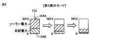
SOCインジケータ154は、蓄電装置100のSOCをユーザに視覚的に認識させるための画像である。本実施の形態においては、SOCインジケータ154の下端がSOCの下限値(0%)を示し、SOCインジケータ154の上端が制御上限値MAX(たとえば100%)を示す。したがって、SOCインジケータ154の高さが、蓄電装置100の満充電容量を示す。 The
SOCインジケータ154の内側には、ソーラー電力を由来とするSOCを示すソーラ電力領域(第1SOC領域)154Aと、系統電力を由来とするSOCを示す系統電力領域(第2SOC領域)154Bとが同じ幅で上下に並べて区別して表示される。したがって、ソーラ電力領域154Aの高さ(大きさ)がソーラー電力を由来とするSOCに相当し、系統電力領域154Bの高さ(大きさ)が系統電力を由来とするSOCに相当し、ソーラ電力領域154Aと系統電力領域154Bとを合わせた高さ(大きさ)が全体のSOCに相当する。なお、図5には、SOCインジケータ154の下側に系統電力領域154Bが表示され、その上側にソーラ電力領域154Aが表示される例が示されている。 Inside the
ユーザは、SOC表示画面に表示されるSOCインジケータ154を見ることによって、蓄電装置100に蓄えられている電力の由来を視覚的に認識することができる。具体的には、ユーザは、SOCインジケータ154に表示される、ソーラ電力領域154Aおよび系統電力領域154Bの高さを確認することによって、ソーラー電力と系統電力とが蓄電装置100にどの程度蓄えられているのかを把握することができる。これにより、ユーザは、地球環境への貢献を実感することができる。 The user can visually recognize the origin of the electric power stored in the
なお、上述の第1設定画面(図2参照)においてユーザが選択ボタン151BをタッチしてSOC表示画面にソーラー電力を表示させないことを選択した場合、SOC表示画面に表示されるSOCインジケータ154には、ソーラ電力領域154Aと系統電力領域154Bとが区別されることなく、その合計のみが表示される。 When the user touches the selection button 151B on the above-mentioned first setting screen (see FIG. 2) and selects not to display the solar power on the SOC display screen, the
SOC表示画面のSOCインジケータ154にソーラ電力領域154Aと系統電力領域154Bとが区別して表示される場合において、ECU130は、SOCが変化した場合のSOCの表示態様を、上述の第3設定画面(図4参照)でユーザが選択した表示モードに応じて切り替える。 When the
図6は、第1表示モード中における蓄電装置100の放電(SOCの低下)に伴なうSOCインジケータ154の表示内容の遷移の一例を示す図である。図7は、第2表示モード中における蓄電装置100の放電(SOCの低下)に伴なうSOCインジケータ154の表示内容の遷移の一例を示す図である。図8は、第3表示モード中における蓄電装置100の放電(SOCの低下)に伴なうSOCインジケータ154の表示内容の遷移の一例を示す図である。なお、図6〜8には、SOCインジケータ154の下側に系統電力領域154Bが表示され、その上側にソーラ電力領域154Aが表示される例が示されている。 FIG. 6 is a diagram showing an example of the transition of the display content of the
図6に示すように、第1表示モード(ソーラー電力を優先して消費しているように表示する表示モード)においては、ECU130は、蓄電装置100の放電に応じて、系統電力領域154Bの高さ(大きさ)を維持しつつ、ソーラ電力領域154Aの高さ(大きさ)を減少させる。これにより、系統電力よりもソーラー電力を優先的に消費しているかような感覚をユーザに抱かせることができる。そのため、ユーザは地球環境への貢献をさらに実感できるようになり、ユーザの満足度をアップすることができる。 As shown in FIG. 6, in the first display mode (display mode in which solar power is preferentially consumed), the
また、第1表示モードにおいて、蓄電装置100の放電に応じてソーラ電力領域154Aの高さを減少させたことによってソーラ電力領域154Aが表示されなくなったときは、ECU130は、その後の蓄電装置100の放電に応じて系統電力領域154Bの高さを減少させる。これにより、第1表示モードにおいて、ソーラー電力を優先的に消費し終えた後に、系統電力を消費しているかのような感覚をユーザに抱かせることができる。 Further, in the first display mode, when the height of the
図7に示すように、第2表示モード(系統電力を優先して消費しているように表示する表示モード)においては、ECU130は、蓄電装置100の放電に応じて、ソーラ電力領域154Aの高さ(大きさ)を維持しつつ、系統電力領域154Bの高さ(大きさ)を減少させる。これにより、系統電力を優先的に消費しているかような感覚をユーザに抱かせることができる。 As shown in FIG. 7, in the second display mode (display mode in which the system power is displayed as if it is preferentially consumed), the
また、第2表示モードにおいて、蓄電装置100の放電に応じて系統電力領域154Bの高さを減少させたことによって系統電力領域154Bが表示されなくなったときは、ECU130は、その後の蓄電装置100の放電に応じてソーラ電力領域154Aの高さを減少させる。 Further, in the second display mode, when the
図8に示すように、第3表示モード(優先的に消費する電力を指定しない表示モード)においては、ECU130は、蓄電装置100の放電に応じて、ソーラ電力領域154Aの高さと系統電力領域154Bの高さとの比率を維持しつつ、ソーラ電力領域154Aの高さおよび系統電力領域154Bの高さを減少させる。これにより、蓄電装置100に蓄えられている電力を使い切る直前までSOCインジケータ154内にソーラ電力領域154Aの表示が残るようになる。そのため、蓄電装置100に蓄えられている電力を使い切る直前までソーラー電力が蓄電装置100に充電されたことをユーザに認識させることができる。 As shown in FIG. 8, in the third display mode (display mode in which the power to be preferentially consumed is not specified), the
以上のように、本実施の形態による車両10は、外部の電力設備20から供給される電力で充電可能に構成された蓄電装置100と、ディスプレイを有するHMI装置150とを備える。HMI装置150には、蓄電装置100のSOCが、蓄電装置100に蓄えられる電力の由来毎に区別して表示される。これにより、ユーザは、HMI装置150を見ることによって、車両10の蓄電装置100に蓄えられている電力の由来を視覚的に認識することができる。 As described above, the
[実施の形態1の変形例1]
上述の実施の形態1においては、図2〜図5にそれぞれ示される第1設定画面、第2設定画面、第3設定画面、およびSOC表示画面が、いずれも車両10のHMI装置150に表示される例を示した。[
In the first embodiment described above, the first setting screen, the second setting screen, the third setting screen, and the SOC display screen shown in FIGS. 2 to 5 are all displayed on the
しかしながら、図2〜図5に示される各画面を、車両10のHMI装置150に加えて、車両10および電力設備20と通信するユーザ端末700のHMI装置720に表示させるようにしてもよい。このようにすることで、ユーザは自らが所持するユーザ端末700を用いて各種の設定および確認を容易に行なうことができる。 However, each screen shown in FIGS. 2 to 5 may be displayed on the
[実施の形態1の変形例2]
上述の実施の形態1においては、図5に示されるSOC表示画面において、SOCインジケータ154の内側にソーラ電力領域154Aと系統電力領域154Bとを上下に並べて表示する例を示した。[Modification 2 of Embodiment 1]
In the first embodiment described above, on the SOC display screen shown in FIG. 5, an example is shown in which the
しかしながら、ソーラ電力領域154Aと系統電力領域154Bとの並べ方は上記のものに限定されない。たとえば、SOCインジケータ154の内側にソーラ電力領域154Aと系統電力領域154Bとを左右に並べて表示するようにしてもよい。 However, the arrangement of the
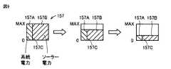
図9は、本変形例によるSOCインジケータ157の表示内容、および第3表示モード(優先的に消費する電力を指定しない表示モード)中におけるSOCインジケータ157の表示内容の遷移の一例を示す図である。 FIG. 9 is a diagram showing an example of the display contents of the
SOCインジケータ157の下端はSOCの下限値(0%)を示し、SOCインジケータ157の上端は制御上限値MAX(たとえば100%)を示す。 The lower end of the
SOCインジケータ157の内側には、ソーラー電力を由来とするSOCを示すソーラ電力領域157Aと、系統電力を由来とするSOCを示す系統電力領域157Bとが同じ高さで左右に並べて表示される。SOCインジケータ157の幅全体に対する、ソーラ電力領域157Aと系統電力領域157Bとの境界線157Cが、ソーラ電力と系統電力との比率に相当する。 Inside the
そして、ECU130は、蓄電装置100の放電に応じて、ソーラ電力領域157Aの幅および系統電力領域157Bの幅を変化させることなく、ソーラ電力領域157Aの高さおよび系統電力領域157Bの高さを均等に減少させる。これにより、蓄電装置100の放電によってSOCが低下しても、SOCインジケータ157の幅全体に対する境界線157Cの位置が同じ位置に維持される。そのため、ソーラ電力と系統電力とが均等に消費されているかのような感覚をより的確にユーザに与えることができる。 Then, the
[実施の形態1の変形例3]
上述の実施の形態1においては、図5のSOC表示画面に表示されるSOCインジケータ154の内側に区別して表示される電力由来の種類として、ソーラー電力および系統電力の2種類を表示する例を示した。[
In the first embodiment described above, an example of displaying two types of electric power, solar power and system power, as power-derived types displayed separately inside the
しかしながら、SOCインジケータ154の内側に区別して表示される電力由来の種類は、ソーラー電力および系統電力の2種類に限定されるものではない。たとえば、ソーラー電力および系統電力に加えて、車両10に搭載される動力出力装置135が発電した電力を、SOCインジケータ154の内側に区別して表示するようにしてもよい。 However, the power-derived types displayed separately inside the
[実施の形態2]
上述の実施の形態1においては、上述のように、電力設備20から車両10に供給される電力にはソーラー電力と系統電力とが含まれ得る。地球環境を保全する意識の高いユーザにおいては、自身が利用する車両10の蓄電装置100を系統電力ではなくソーラー電力で充電したいというニーズが高まることが想定される。[Embodiment 2]
In the above-described first embodiment, as described above, the electric power supplied from the
このようなユーザのニーズを踏まえ、本実施の形態2による車両10においては、蓄電装置100のSOCを電力の由来毎に区別して表示する機能に加えて、電力設備20から供給される電力で車両10の蓄電装置100が充電される際にソーラー電力に合せて蓄電装置100の充電電力を変更する機能を備える。その他の構造、機能、処理は、上述の実施の形態1と同じであるため、ここでの詳細な説明は繰返さない。 Based on such user needs, in the
図10は、車両10のHMI装置150に表示される充電選択画面の一例を示す図である。充電選択画面は、ソーラー電力を優先的に充電するか否かをユーザが選択するための画面である。充電選択画面には、「系統電力よりもソーラー電力を優先的に充電しますか?」というメッセージ、YESボタン,NOボタンなどが表示される。 FIG. 10 is a diagram showing an example of a charge selection screen displayed on the
ユーザが充電選択画面に示されるYESボタンをタッチすると、系統電力よりもソーラー電力を優先的に充電する「ソーラー充電モード」が選択される。ユーザが充電選択画面に示されるNOボタンをタッチすると、優先的に充電する電力を指定しない「通常モード」が選択される。なお、ユーザによる選択結果はECU130のメモリに記憶される。 When the user touches the YES button displayed on the charging selection screen, the "solar charging mode" in which the solar power is preferentially charged over the grid power is selected. When the user touches the NO button displayed on the charge selection screen, the "normal mode" in which the power to be charged preferentially is not specified is selected. The selection result by the user is stored in the memory of the
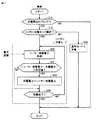
図11は、電力設備20から供給される電力で蓄電装置100を充電する際に車両10のECU130が行なう処理手順の一例を示すフローチャートである。 FIG. 11 is a flowchart showing an example of a processing procedure performed by the
ECU130は、電力設備20による蓄電装置100の充電開始タイミングであるか否かを判定する(ステップS10)。充電開始タイミングでない場合(ステップS10においてNO)、ECU130は、以降の処理をスキップして処理を終了する。 The
充電開始タイミングである場合(ステップS10においてYES)、ECU130は、上述の図10に示す充電選択画面を表示し、ユーザによってソーラー充電モードが選択されたか否かを判定する(ステップS12)。 When it is the charging start timing (YES in step S10), the
ソーラー充電モードが選択されなかった場合(ステップS12においてNO)、ECU130は、通常モードで蓄電装置100を充電する(ステップS30)。たとえば、ECU130は、蓄電装置100の充電電力を予め定められた固定値に設定し、設定された充電電力で蓄電装置100を充電するように電力変換器114を制御する。 When the solar charging mode is not selected (NO in step S12), the
一方、ソーラー充電モードが選択された場合(ステップS12においてYES)、ECU130は、ソーラー充電モードで蓄電装置100を充電する(ステップS42〜S48)。 On the other hand, when the solar charging mode is selected (YES in step S12), the
具体的には、ECU130は、まず、現在のソーラー発電電力の情報を電力設備20から取得する(ステップS42)。そして、ECU130は、現在のソーラー発電電力と蓄電装置100の充電電力との差(絶対値)が所定値を超えているか否かを判定する(ステップS44)。なお、所定値は非常に小さい値に設定される。 Specifically, the
差が所定値を超えている場合(ステップS44においてYES)、ECU130は、蓄電装置100の充電電力を現在のソーラー発電電力に変更する(ステップS46)。すなわち、ECU130は、蓄電装置100の充電電力を現在のソーラー発電電力と同じ値に設定し、設定された充電電力で蓄電装置100を充電するように電力変換器114を制御する。その後、ECU130は、処理をステップS48に移す。 When the difference exceeds a predetermined value (YES in step S44), the
差が所定値を超えていない場合(ステップS44においてNO)、ECU130は、蓄電装置100の充電電力を現在の値に維持したまま、処理をステップS48に移す。 If the difference does not exceed a predetermined value (NO in step S44), the
次いで、ECU130は、蓄電装置100の充電が完了した(SOCが目標値に達した)か否かを判定する(ステップS48)。充電が完了していない場合(ステップS48においてNO)、ECU130は、処理をステップS42に戻し、充電が完了するまでステップS42以降の処理を繰り返す。充電が完了した場合(ステップS48においてYES)、ECU130は、処理を終了する。 Next, the
図12は、ソーラー充電モードで蓄電装置100が充電される場合における、ソーラー発電電力および蓄電装置100の充電電力の変化の一例を示す図である。図12に示すように、ソーラー充電モードでは、蓄電装置100の充電電力がソーラー発電電力とほぼ一致するように調整される。すなわち、ソーラー発電電力が増加したことに応じて蓄電装置100の充電電力がソーラー発電電力に追従するように増加され、ソーラー発電電力が減少したことに応じて蓄電装置100の充電電力がソーラー発電電力に追従するように減少される。 FIG. 12 is a diagram showing an example of changes in the solar power generation power and the charging power of the
これにより、計算上、ソーラー発電電力がそのまま蓄電装置100に充電されることになる。その結果、ソーラー電力をより多く蓄電装置100に取り込むことが可能となる。 As a result, in calculation, the solar power generation power is charged to the
また、上記のソーラー充電モードはユーザによって選択されるものである。そのため、ユーザの要求に応じてソーラー電力をより多く蓄電装置100に取り込むことが可能となり、蓄電装置100をソーラー電力で充電したいというユーザのニーズに答えることができる。 Further, the above solar charging mode is selected by the user. Therefore, it is possible to take in more solar power into the
[実施の形態2の変形例1]
上述の図11のフローチャートの処理を、電力設備20のHEMS300のCPU340が車両10と通信しながら実行するようにしてもよい。[
The processing of the flowchart of FIG. 11 may be executed while the
図13は、電力設備20から供給される電力で蓄電装置100を充電する際にHEMS300のCPU340が行なう処理手順の一例を示すフローチャートである。図13のフローチャートに示すステップS10A〜S48Aは、上述の図11のフローチャートに示すステップS10〜S48にそれぞれ対応する処理である。 FIG. 13 is a flowchart showing an example of a processing procedure performed by the
すなわち、HEMS300は、充電開始タイミングである場合(ステップS10AにおいてYES)、車両10との通信を行なってソーラー充電モードが選択されたか否かを判定する(ステップS12A)。そして、ソーラー充電モードが選択されなかった場合(ステップS12AにおいてNO)、HEMS300は、車両10との通信を行なって通常モードで蓄電装置100を充電する(ステップS30A)。 That is, when it is the charging start timing (YES in step S10A), the
一方、ソーラー充電モードが選択された場合(ステップS12AにおいてYES)、HEMS300は、車両10との通信を行なってソーラー充電モードで蓄電装置100を充電する(ステップS42A〜S48A)。 On the other hand, when the solar charging mode is selected (YES in step S12A), the
このように、HEMS300が車両10と通信しながらソーラー充電モードで蓄電装置100を充電するようにしてもよい。 In this way, the
[実施の形態2の変形例2]
ソーラー充電モードで蓄電装置100を充電する際に、蓄電装置100の充電電力に上限値および下限値を設けるようにしてもよい。[Modification 2 of Embodiment 2]
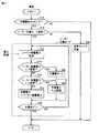
When charging the
図14は、電力設備20から供給される電力で蓄電装置100を充電する際の蓄電装置100の充電電力と充電システム全体の効率(以下、単に「システム効率」ともいう)との関係の一例を示す図である。蓄電装置100の充電電力が低い領域においては、充電電力が低いほどシステム効率が低下する傾向にある。そこで、本変形例では、システム効率が効率下限値となるときの蓄電装置100の充電電力が、蓄電装置100の充電電力の下限値PLに設定されている。また、実際の充電が電力変換器114によって行なわれることを考慮して、電力変換器114の仕様(たとえば出力上限値など)によって蓄電装置100の充電電力の上限値PUが決められている。 FIG. 14 shows an example of the relationship between the charging power of the
図15は、電力設備20から供給される電力で蓄電装置100を充電する際に本変形例による車両10のECU130が行なう処理手順の一例を示すフローチャートである。図15のフローチャートは、図11のフローチャートに示すステップS44,S46をステップS50〜S58に変更したものである。その他のステップ(上述の図11に示したステップと同じ番号を付しているステップ)については、既に説明したため詳細な説明はここでは繰り返さない。 FIG. 15 is a flowchart showing an example of a processing procedure performed by the
ECU130は、ソーラー充電モードにおいて、電力設備20から取得した現在のソーラー発電電力が充電電力の下限値PL未満であるか否かを判定する(ステップS50)。現在のソーラー発電電力が下限値PL未満である場合(ステップS50においてYES)、ECU130は、蓄電装置100の充電電力が「0」となるように電力変換器114を制御する(ステップS52)。すなわち、ECU130は、蓄電装置100の充電を行なわない。 The
現在のソーラー発電電力が下限値PL未満でない場合(ステップS50においてNO)、ECU130は、現在のソーラー発電電力が充電電力の上限値PUを超えているか否かを判定する(ステップS54)。ソーラー発電電力が上限値PUを超えている場合(ステップS54においてYES)、ECU130は、蓄電装置100の充電電力が上限値PUとなるように電力変換器114を制御する(ステップS56)。 When the current solar power generation power is not less than the lower limit value PL (NO in step S50), the
現在のソーラー発電電力が上限値PUを超えていない場合(ステップS54においてNO)、ECU130は、蓄電装置100の充電電力が現在のソーラー発電電力となるように電力変換器114を制御する(ステップS58)。 When the current solar power generation power does not exceed the upper limit value PU (NO in step S54), the
図16は、本変形例によるソーラー充電モードで蓄電装置100が充電される場合のソーラー発電電力および蓄電装置100の充電電力の変化の一例を示す図である。 FIG. 16 is a diagram showing an example of changes in the solar power generation power and the charging power of the
図16に示すように、ソーラー発電電力が上限値PUを超える時間帯(時刻t2〜t3)においては、蓄電装置100の充電電力が上限値PUに制限される。ソーラー発電電力が下限値PL未満となる時間帯(時刻t1以前、時刻t4以降)においては、システム効率が低下することを考慮して蓄電装置100の充電が行なわれない。 As shown in FIG. 16, in the time zone (time t2 to t3) when the solar power generation power exceeds the upper limit value PU, the charging power of the
このように、ソーラー充電モードで蓄電装置100を充電する際に、蓄電装置100の充電電力に、システム効率などを考慮した下限値PLおよび上限値PUを設けるようにしてもよい。これにより、ソーラー発電電力を効率的に蓄電装置100に充電することができる。 As described above, when charging the
[実施の形態2の変形例3]
ソーラー発電電力は、家屋600内で使用される負荷装置400においても消費され得る。ユーザは、家屋600内の負荷装置400においても系統電力を消費することなくソーラー発電電力を消費することを望んできることが想定される。[
The photovoltaic power generation can also be consumed in the
この点を考慮し、ソーラー充電モードで蓄電装置100を充電する際に、ソーラー発電電力から負荷装置400の消費電力を差し引いた電力(以下「ソーラー余剰電力」ともいう)で蓄電装置100を充電するようにしてもよい。 In consideration of this point, when charging the
図17は、電力設備20から供給される電力で蓄電装置100を充電する際に本変形例による車両10のECU130が行なう処理手順の一例を示すフローチャートである。図17のフローチャートは、図11のフローチャートに示すステップS42,S44,S46をそれぞれステップS43,S45,S47に変更したものである。その他のステップ(上述の図11に示したステップと同じ番号を付しているステップ)については、既に説明したため詳細な説明はここでは繰り返さない。 FIG. 17 is a flowchart showing an example of a processing procedure performed by the
ECU130は、ソーラー充電モードにおいて、現在のソーラー余剰電力の情報を電力設備20から取得する(ステップS43)。そして、ECU130は、現在のソーラー余剰電力と蓄電装置100の充電電力との差(絶対値)が所定値を超えているか否かを判定する(ステップS45)。 The
差が所定値を超えている場合(ステップS45においてYES)、ECU130は、蓄電装置100の充電電力を現在のソーラー余剰電力に変更する(ステップS47)。その後、ECU130は、処理をステップS48に移す。 When the difference exceeds a predetermined value (YES in step S45), the
差が所定値を超えていない場合(ステップS45においてNO)、ECU130は、蓄電装置100の充電電力を現在の値に維持したまま、処理をステップS48に移す。 When the difference does not exceed a predetermined value (NO in step S45), the
このようすることで、ソーラー充電モードで蓄電装置100を充電する際に、家屋600内の負荷装置400においても系統電力を消費することなく、ソーラー発電電力を消費することができる。 By doing so, when charging the
上述した実施の形態1、実施の形態1の変形例1〜3、実施の形態2、実施の形態2の変形例1〜3については、技術的な矛盾が生じない範囲で適宜組合せることも可能である。 The above-described first embodiment, modified examples 1 to 3 of the first embodiment, and modified examples 1 to 3 of the second embodiment and the second embodiment may be appropriately combined as long as there is no technical contradiction. It is possible.
今回開示された実施の形態はすべての点で例示であって制限的なものではないと考えられるべきである。本開示の範囲は上記した説明ではなくて特許請求の範囲によって示され、特許請求の範囲と均等の意味および範囲内でのすべての変更が含まれることが意図される。 It should be considered that the embodiments disclosed this time are exemplary in all respects and not restrictive. The scope of the present disclosure is shown by the scope of claims rather than the above description, and is intended to include all modifications within the meaning and scope equivalent to the scope of claims.
10 車両、20 電力設備、100 蓄電装置、112,212 コネクタ、114 電力変換器、130 ECU、135 動力出力装置、140,240,350,730 通信装置、150,720 HMI装置、152 SOCサンプルインジケータ、154,157 SOCインジケータ、154A,157A ソーラ電力領域、154B,157B 系統電力領域、200 電力スタンド、210 リレー、214 電力ケーブル、218 電力線、230 コントローラ、310 DC/DCコンバータ、315 DC/ACコンバータ、330 蓄電池、360 操作パネル、400 負荷装置、416 ソーラーパネル、417 電力センサ、500 系統電源、510 配電盤、520 ブレーカ、600 家屋、700 ユーザ端末、710 制御装置。 10 vehicles, 20 power equipment, 100 power storage devices, 112,212 connectors, 114 power converters, 130 ECUs, 135 power output devices, 140, 240, 350, 730 communication devices, 150, 720 HMI devices, 152 SOC sample indicators, 154,157 SOC indicator, 154A, 157A Solar power area, 154B, 157B system power area, 200 power stand, 210 relay, 214 power cable, 218 power line, 230 controller, 310 DC / DC converter, 315 DC / AC converter, 330 Storage battery, 360 operation panel, 400 load device, 416 solar panel, 417 power sensor, 500 system power supply, 510 power grid, 520 breaker, 600 house, 700 user terminal, 710 control device.
Claims (6)
Translated fromJapanese前記蓄電装置のSOCを前記蓄電装置に蓄えられる電力の由来毎に区別して表示するように構成された表示装置とを備え、
前記表示装置は、太陽光を用いて発電された第1電力を由来とする第1SOC領域と、系統電源から供給された第2電力を由来とする第2SOC領域とを区別して表示し、
前記表示装置に表示される前記第1SOC領域の大きさおよび前記第2SOC領域の大きさを制御可能に構成された制御装置をさらに備え、
前記第1SOC領域と前記第2SOC領域とは前記表示装置のインジケータ内に同じ高さで幅方向に並べて表示され、
前記インジケータの幅全体に対する前記第1SOC領域と前記第2SOC領域との境界の位置が前記第1電力と前記第2電力との比率に相当する位置であり、
前記制御装置は、優先して消費しているように表示する電力を指定しない表示モードをユーザが選択している場合、前記蓄電装置の放電に応じて、前記第1SOC領域の幅および前記第2SOC領域の幅を変化させることなく、前記第1SOC領域の高さおよび前記第2SOC領域の高さを均等に減少させる、車両。A power storage device that can be charged with the power supplied from an external power facility,
It is provided with a display device configured to display the SOC of the power storage device separately according to the origin of the electric power stored in the power storage device.
The display device distinguishes between a first SOC region derived from the first electric power generated by using sunlight and a second SOC region derived from the second electric power supplied from the grid power supply.
A control device configured to be able to control the size of the first SOC region and the size of the second SOC region displayed on the display device is further provided.
The first SOC area and the second SOC area are displayed side by side in the width direction at the same height in the indicator of the display device.
The position of the boundary between the first SOC region and the second SOC region with respect to the entire width of the indicator is a position corresponding to the ratio of the first power to the second power.
When the user selects a display mode in which the power to be displayed as preferentially consumed by the control device is not specified, the width of the first SOC region and the second SOC according to the discharge of the power storage device. A vehiclethat evenly reduces the height of the first SOC region and the height of the second SOC region without changing the width of the region.
前記車両は、前記電力設備から前記蓄電装置に供給される電力を調整可能に構成された電力変換器をさらに備え、
前記制御装置は、前記電力設備から供給される電力で前記蓄電装置が充電される際に、前記太陽光発電装置の発電電力に応じて前記蓄電装置の充電電力が変更されるように前記電力変換器を制御する、請求項2〜4のいずれかに記載の車両。The electric power equipment is equipped with a photovoltaic power generation device.
The vehicle further comprises a power converter configured to be able to adjust the power supplied from the power equipment to the power storage device.
The control device converts the power so that when the power storage device is charged by the power supplied from the power equipment, the charging power of the power storage device is changed according to the power generated by the solar power generation device. The vehicle according to any one ofclaims 2 to 4 , which controls a device.
Priority Applications (4)
| Application Number | Priority Date | Filing Date | Title |
|---|---|---|---|
| JP2017225969AJP6981204B2 (en) | 2017-11-24 | 2017-11-24 | vehicle |
| CN201811367067.3ACN110015074A (en) | 2017-11-24 | 2018-11-16 | Vehicle |
| US16/193,619US10873197B2 (en) | 2017-11-24 | 2018-11-16 | Vehicle with display for separately showing grid based SOC and solar based SOC of vehicle battery |
| EP18207084.7AEP3489070A1 (en) | 2017-11-24 | 2018-11-19 | Electric or hybrid vehicle with state of charge display based on origins of charge and control thereof |
Applications Claiming Priority (1)
| Application Number | Priority Date | Filing Date | Title |
|---|---|---|---|
| JP2017225969AJP6981204B2 (en) | 2017-11-24 | 2017-11-24 | vehicle |
Publications (2)
| Publication Number | Publication Date |
|---|---|
| JP2019097333A JP2019097333A (en) | 2019-06-20 |
| JP6981204B2true JP6981204B2 (en) | 2021-12-15 |
Family
ID=64362452
Family Applications (1)
| Application Number | Title | Priority Date | Filing Date |
|---|---|---|---|
| JP2017225969AExpired - Fee RelatedJP6981204B2 (en) | 2017-11-24 | 2017-11-24 | vehicle |
Country Status (4)
| Country | Link |
|---|---|
| US (1) | US10873197B2 (en) |
| EP (1) | EP3489070A1 (en) |
| JP (1) | JP6981204B2 (en) |
| CN (1) | CN110015074A (en) |
Families Citing this family (15)
| Publication number | Priority date | Publication date | Assignee | Title |
|---|---|---|---|---|
| US11165254B2 (en)* | 2018-09-18 | 2021-11-02 | Sinewatts, Inc. | Systems and methods for electricity generation, storage, distribution, and dispatch |
| WO2021038683A1 (en)* | 2019-08-26 | 2021-03-04 | 三菱電機株式会社 | Charge/discharge control device, charge/discharge system, charge/discharge control method, and program |
| AU2020392112B2 (en)* | 2019-11-25 | 2023-03-30 | Enphase Energy, Inc. | Methods and apparatus for grid connectivity control |
| CN111516498B (en)* | 2020-05-12 | 2022-04-12 | 安徽安凯汽车股份有限公司 | Double-battery system safety application control method |
| CN111591280B (en)* | 2020-05-25 | 2021-10-29 | 潍柴动力股份有限公司 | A series hybrid power output control method, device and vehicle |
| CN111845388A (en)* | 2020-07-29 | 2020-10-30 | 广州小鹏车联网科技有限公司 | Method and device for supplementing energy between vehicles |
| JP7581976B2 (en)* | 2021-03-05 | 2024-11-13 | トヨタ自動車株式会社 | Display control device, vehicle, display control method, and control program |
| JP7661772B2 (en)* | 2021-05-11 | 2025-04-15 | トヨタ自動車株式会社 | Hydrogen gas information display system |
| AU2022277881B2 (en)* | 2021-05-18 | 2025-01-02 | Enphase Energy, Inc. | Method and apparatus for controlling loads connected to a distributed energy generation system |
| WO2023068072A1 (en)* | 2021-10-22 | 2023-04-27 | パナソニックIpマネジメント株式会社 | Electric vehicle charge management apparatus |
| JP7528979B2 (en)* | 2022-04-28 | 2024-08-06 | トヨタ自動車株式会社 | Vehicle Information System |
| JP7580425B2 (en)* | 2022-04-28 | 2024-11-11 | 本田技研工業株式会社 | DISPLAY CONTROL DEVICE, DISPLAY CONTROL METHOD, AND PROGRAM |
| JP2024017614A (en)* | 2022-07-28 | 2024-02-08 | トヨタ自動車株式会社 | Computing device, vehicle, management server, and computing method |
| WO2024057382A1 (en)* | 2022-09-13 | 2024-03-21 | 日産自動車株式会社 | Information management method and information management device |
| WO2025041301A1 (en)* | 2023-08-23 | 2025-02-27 | 株式会社Subaru | Display device |
Family Cites Families (68)
| Publication number | Priority date | Publication date | Assignee | Title |
|---|---|---|---|---|
| JP3009589B2 (en)* | 1994-05-26 | 2000-02-14 | キヤノン株式会社 | Solar cell power generation capability detection device and device using solar cell |
| US5686809A (en)* | 1995-05-12 | 1997-11-11 | Fuji Photo Film Co., Ltd. | Combination solar and external battery powered camera battery charger |
| JP2003079054A (en)* | 2001-08-31 | 2003-03-14 | Sanyo Electric Co Ltd | Solar power generation system having storage battery |
| JP2009506742A (en)* | 2005-08-24 | 2009-02-12 | トーマス エイ ウォード | Hybrid vehicle having a low voltage solar panel that charges a high voltage battery using a series charger that separately charges each cell of the high voltage battery connected in series |
| US8712650B2 (en)* | 2005-11-17 | 2014-04-29 | Invent.Ly, Llc | Power management systems and designs |
| US20080094025A1 (en)* | 2006-10-20 | 2008-04-24 | Rosenblatt Michael N | Solar cells on portable devices |
| JP4365429B2 (en) | 2007-07-24 | 2009-11-18 | トヨタ自動車株式会社 | Navigation device for displaying charging information and vehicle equipped with the device |
| JP4450087B2 (en)* | 2008-03-31 | 2010-04-14 | トヨタ自動車株式会社 | Hybrid vehicle and control method thereof |
| US8080972B2 (en)* | 2008-06-02 | 2011-12-20 | Goal Zero Llc | System and method for storing and releasing energy |
| WO2010022059A1 (en)* | 2008-08-18 | 2010-02-25 | Austin Christopher B | Vehicular battery charger, charging system, and method |
| JP5420883B2 (en)* | 2008-11-17 | 2014-02-19 | トヨタ自動車株式会社 | Charging connector and charging cable unit |
| JP5123144B2 (en)* | 2008-11-21 | 2013-01-16 | 矢崎総業株式会社 | Charging connector |
| US8203237B1 (en)* | 2009-01-15 | 2012-06-19 | Cowles Scott R | Portable power generating unit |
| US8120310B2 (en)* | 2009-04-17 | 2012-02-21 | General Electric Company | Methods and systems for charging electric vehicles using solar power |
| CN102763302A (en)* | 2009-08-11 | 2012-10-31 | 威罗门飞行公司 | Energy Storage and Charging Devices |
| KR101604696B1 (en)* | 2009-08-12 | 2016-03-18 | 엘지전자 주식회사 | Mobile terminal and method for controlling power source thereof |
| EP2287702B1 (en)* | 2009-08-17 | 2018-05-02 | Lg Electronics Inc. | Mobile terminal and display controlling method thereof |
| KR101578738B1 (en)* | 2009-08-31 | 2015-12-21 | 엘지전자 주식회사 | Charging method of mobile terminal |
| JP5223822B2 (en)* | 2009-09-11 | 2013-06-26 | トヨタ自動車株式会社 | Display device and hybrid vehicle including the same |
| JP5513819B2 (en)* | 2009-09-15 | 2014-06-04 | パナソニック株式会社 | Power distribution system |
| KR101606065B1 (en)* | 2009-11-06 | 2016-03-25 | 엘지전자 주식회사 | Portable terminal |
| KR101617267B1 (en)* | 2009-12-07 | 2016-05-02 | 엘지전자 주식회사 | Mobile terminal and method for controlling charging thereof |
| KR101537621B1 (en)* | 2009-12-23 | 2015-07-17 | 엘지전자 주식회사 | Mobile terminal and method for notifying charging state thereof |
| JP2011163858A (en)* | 2010-02-08 | 2011-08-25 | Toyota Motor Corp | Energy display system |
| US8907614B2 (en)* | 2010-03-25 | 2014-12-09 | Honda Motor Co., Ltd. | Photovoltaic power generation system |
| US8768533B2 (en)* | 2010-04-09 | 2014-07-01 | Toyota Jidosha Kabushiki Kaisha | Vehicle, communication system, and communication device |
| US20110252678A1 (en)* | 2010-04-12 | 2011-10-20 | Dale Jones | Method, apparatus and system for constant led night brightness based on daytime solar charging |
| JP5427105B2 (en)* | 2010-05-14 | 2014-02-26 | 株式会社豊田自動織機 | Resonant contactless power supply system |
| JP2012009819A (en)* | 2010-05-28 | 2012-01-12 | Sony Corp | Photovoltaic power generation device |
| JP5505932B2 (en)* | 2010-07-16 | 2014-05-28 | トヨタ自動車株式会社 | Charging system |
| CN103052528B (en)* | 2010-08-10 | 2015-07-29 | 丰田自动车株式会社 | Power information communication device |
| EP2426804A1 (en)* | 2010-09-02 | 2012-03-07 | ABB Research Ltd. | Charging of electrical vehicles |
| JP5653701B2 (en)* | 2010-09-28 | 2015-01-14 | 三菱電機株式会社 | Charge display device |
| JP2012110170A (en)* | 2010-11-19 | 2012-06-07 | Hitachi Ltd | Controller for power storage device, power storage device, charging/discharging method of power storage device |
| EP2485356A1 (en)* | 2011-02-02 | 2012-08-08 | Arista Power, Inc. | Energy storage and power management system |
| BR112013022575A2 (en)* | 2011-03-04 | 2017-10-31 | Suzhou Eagle Elec Vehicle Mfg | set of electrical system of an electric car, power system and drive device of the same |
| JP2012186950A (en)* | 2011-03-07 | 2012-09-27 | Denso Corp | Electric power supply system |
| JP5516525B2 (en)* | 2011-07-20 | 2014-06-11 | トヨタ自動車株式会社 | Driving assistance device |
| JP5672186B2 (en)* | 2011-07-24 | 2015-02-18 | 株式会社デンソー | Power supply system |
| EP2574995B1 (en)* | 2011-09-28 | 2020-06-17 | ETA SA Manufacture Horlogère Suisse | Electromechanical timepiece with an additional function |
| WO2013057786A1 (en)* | 2011-10-18 | 2013-04-25 | トヨタ自動車株式会社 | Power feeding device, and power feeding method |
| JP6062682B2 (en)* | 2012-08-15 | 2017-01-18 | 本田技研工業株式会社 | Travel management system with renewable energy |
| US20140062191A1 (en)* | 2012-08-29 | 2014-03-06 | Robert L. Bryson | Low Voltage Solar Electric Energy Distribution |
| US20140062206A1 (en)* | 2012-08-29 | 2014-03-06 | Robert L. Bryson | Low Voltage Solar Electric Energy Distribution |
| US9178356B2 (en)* | 2012-08-29 | 2015-11-03 | Robert L. Bryson | Low voltage solar electric energy distribution |
| JP6040643B2 (en)* | 2012-09-04 | 2016-12-07 | 日産自動車株式会社 | Battery status display device |
| US9694973B2 (en)* | 2012-11-04 | 2017-07-04 | Dratonx, Inc | Electrical powered weight and fullness level system |
| US9561733B2 (en)* | 2013-01-25 | 2017-02-07 | Toyota Jidosha Kabushiki Kaisha | On-vehicle travel distance output apparatus |
| US20160047212A1 (en)* | 2013-05-25 | 2016-02-18 | Genie Ip B.V. | Wind-heated molten salt as a thermal buffer for producing oil from unconventional resources |
| US9315109B2 (en)* | 2013-11-02 | 2016-04-19 | At&T Intellectual Property I, L.P. | Methods, systems, and products for charging batteries |
| US9592744B2 (en)* | 2013-12-06 | 2017-03-14 | SZ DJI Technology Co., Ltd | Battery and unmanned aerial vehicle with the battery |
| CN103762636B (en)* | 2014-01-09 | 2016-03-02 | 北京京东方能源科技有限公司 | A kind of electronic equipment protection shell |
| EP3859653B1 (en)* | 2014-01-24 | 2024-08-07 | Schneider Electric USA, Inc. | Dynamic adaptable environment resource management controller apparatuses, methods and systems |
| JP6003943B2 (en)* | 2014-04-28 | 2016-10-05 | トヨタ自動車株式会社 | Hybrid vehicle and control method of hybrid vehicle |
| JP6242006B2 (en)* | 2014-05-30 | 2017-12-06 | ニチコン株式会社 | Electric vehicle charger |
| JP6194872B2 (en)* | 2014-11-18 | 2017-09-13 | トヨタ自動車株式会社 | Information processing apparatus for vehicle |
| JP6185945B2 (en)* | 2015-02-23 | 2017-08-23 | 株式会社Subaru | SOC display device for hybrid vehicle |
| JP6068531B2 (en)* | 2015-02-23 | 2017-01-25 | 富士重工業株式会社 | SOC display device for hybrid vehicle |
| JP6156419B2 (en)* | 2015-03-19 | 2017-07-05 | トヨタ自動車株式会社 | vehicle |
| JP6414111B2 (en)* | 2016-03-22 | 2018-10-31 | トヨタ自動車株式会社 | Display device |
| JP6361681B2 (en)* | 2016-03-30 | 2018-07-25 | トヨタ自動車株式会社 | Hybrid car |
| JP6436124B2 (en)* | 2016-03-30 | 2018-12-12 | トヨタ自動車株式会社 | Hybrid car |
| US10427534B2 (en)* | 2016-11-22 | 2019-10-01 | Shenzhen Dansha Technology Co., Ltd. | Infrared automobile charging system |
| JP6481676B2 (en)* | 2016-12-06 | 2019-03-13 | トヨタ自動車株式会社 | Hybrid vehicle |
| JP6520902B2 (en)* | 2016-12-14 | 2019-05-29 | トヨタ自動車株式会社 | Connected vehicle |
| CN106926713A (en)* | 2017-04-06 | 2017-07-07 | 东汉新能源汽车技术有限公司 | Vehicle multipotency source supply system and method, solar telephone |
| KR101999665B1 (en)* | 2017-08-31 | 2019-07-12 | 주식회사 하이메틱스 | Apparatus and method for simulating consumption of Electric Power Load |
| JP6958286B2 (en)* | 2017-11-24 | 2021-11-02 | トヨタ自動車株式会社 | Vehicle and power control system |
- 2017
- 2017-11-24JPJP2017225969Apatent/JP6981204B2/ennot_activeExpired - Fee Related
- 2018
- 2018-11-16USUS16/193,619patent/US10873197B2/ennot_activeExpired - Fee Related
- 2018-11-16CNCN201811367067.3Apatent/CN110015074A/enactivePending
- 2018-11-19EPEP18207084.7Apatent/EP3489070A1/ennot_activeWithdrawn
Also Published As
| Publication number | Publication date |
|---|---|
| EP3489070A1 (en) | 2019-05-29 |
| CN110015074A (en) | 2019-07-16 |
| US20190165589A1 (en) | 2019-05-30 |
| JP2019097333A (en) | 2019-06-20 |
| US10873197B2 (en) | 2020-12-22 |
Similar Documents
| Publication | Publication Date | Title |
|---|---|---|
| JP6981204B2 (en) | vehicle | |
| US11305667B2 (en) | Vehicle and power control system | |
| CN108407641B (en) | Electric vehicle and its intelligent discharge device | |
| US12134335B2 (en) | Power control system and vehicle | |
| EP2783899B1 (en) | Charging system and charging reservation method | |
| US10000137B2 (en) | Hybrid vehicle with means for disconnection of a depleted auxiliary battery in order to allow for more rapid main battery charging | |
| JP6457782B2 (en) | Method and system for charging an electric vehicle | |
| JP5773055B2 (en) | Vehicle, charging device and charging system | |
| JP5267050B2 (en) | Battery level monitor system | |
| US11914840B2 (en) | Charger map overlay and detail card | |
| CN103959596A (en) | Charging system and charging reservation method | |
| JP6365275B2 (en) | Storage battery control device, power storage system, and storage battery charging method | |
| JP2013184642A (en) | Vehicle and control method for vehicle | |
| JP2015208132A (en) | Electric vehicle charge/discharge apparatus | |
| JP2015037346A (en) | Vehicle charging system and method for charging vehicle power storage device | |
| JP6099145B2 (en) | Charging control device and charging system provided with the same | |
| JP2015097441A (en) | Charge / discharge device | |
| JP7226288B2 (en) | vehicle | |
| JP6022980B2 (en) | Sensor position determination method | |
| JP2015192585A (en) | Electric vehicle charging device and method |
Legal Events
| Date | Code | Title | Description |
|---|---|---|---|
| A621 | Written request for application examination | Free format text:JAPANESE INTERMEDIATE CODE: A621 Effective date:20200428 | |
| A977 | Report on retrieval | Free format text:JAPANESE INTERMEDIATE CODE: A971007 Effective date:20210311 | |
| A131 | Notification of reasons for refusal | Free format text:JAPANESE INTERMEDIATE CODE: A131 Effective date:20210421 | |
| A521 | Request for written amendment filed | Free format text:JAPANESE INTERMEDIATE CODE: A523 Effective date:20210531 | |
| TRDD | Decision of grant or rejection written | ||
| A01 | Written decision to grant a patent or to grant a registration (utility model) | Free format text:JAPANESE INTERMEDIATE CODE: A01 Effective date:20211019 | |
| A61 | First payment of annual fees (during grant procedure) | Free format text:JAPANESE INTERMEDIATE CODE: A61 Effective date:20211101 | |
| R151 | Written notification of patent or utility model registration | Ref document number:6981204 Country of ref document:JP Free format text:JAPANESE INTERMEDIATE CODE: R151 | |
| LAPS | Cancellation because of no payment of annual fees |