JP6980696B2 - Ultrasound imaging and treatment equipment - Google Patents
Ultrasound imaging and treatment equipmentDownload PDFInfo
- Publication number
- JP6980696B2 JP6980696B2JP2018555162AJP2018555162AJP6980696B2JP 6980696 B2JP6980696 B2JP 6980696B2JP 2018555162 AJP2018555162 AJP 2018555162AJP 2018555162 AJP2018555162 AJP 2018555162AJP 6980696 B2JP6980696 B2JP 6980696B2
- Authority
- JP
- Japan
- Prior art keywords
- ultrasonic
- ultrasound
- imaging
- concentric annular
- transducer
- Prior art date
- Legal status (The legal status is an assumption and is not a legal conclusion. Google has not performed a legal analysis and makes no representation as to the accuracy of the status listed.)
- Active
Links
Images


Classifications
- A—HUMAN NECESSITIES
- A61—MEDICAL OR VETERINARY SCIENCE; HYGIENE
- A61B—DIAGNOSIS; SURGERY; IDENTIFICATION
- A61B8/00—Diagnosis using ultrasonic, sonic or infrasonic waves
- A61B8/44—Constructional features of the ultrasonic, sonic or infrasonic diagnostic device
- A61B8/4444—Constructional features of the ultrasonic, sonic or infrasonic diagnostic device related to the probe
- A61B8/4461—Features of the scanning mechanism, e.g. for moving the transducer within the housing of the probe
- A—HUMAN NECESSITIES
- A61—MEDICAL OR VETERINARY SCIENCE; HYGIENE
- A61N—ELECTROTHERAPY; MAGNETOTHERAPY; RADIATION THERAPY; ULTRASOUND THERAPY
- A61N7/00—Ultrasound therapy
- A61N7/02—Localised ultrasound hyperthermia
- B—PERFORMING OPERATIONS; TRANSPORTING
- B06—GENERATING OR TRANSMITTING MECHANICAL VIBRATIONS IN GENERAL
- B06B—METHODS OR APPARATUS FOR GENERATING OR TRANSMITTING MECHANICAL VIBRATIONS OF INFRASONIC, SONIC, OR ULTRASONIC FREQUENCY, e.g. FOR PERFORMING MECHANICAL WORK IN GENERAL
- B06B1/00—Methods or apparatus for generating mechanical vibrations of infrasonic, sonic, or ultrasonic frequency
- B06B1/02—Methods or apparatus for generating mechanical vibrations of infrasonic, sonic, or ultrasonic frequency making use of electrical energy
- B06B1/06—Methods or apparatus for generating mechanical vibrations of infrasonic, sonic, or ultrasonic frequency making use of electrical energy operating with piezoelectric effect or with electrostriction
- B06B1/0607—Methods or apparatus for generating mechanical vibrations of infrasonic, sonic, or ultrasonic frequency making use of electrical energy operating with piezoelectric effect or with electrostriction using multiple elements
- B06B1/0622—Methods or apparatus for generating mechanical vibrations of infrasonic, sonic, or ultrasonic frequency making use of electrical energy operating with piezoelectric effect or with electrostriction using multiple elements on one surface
- B06B1/0625—Annular array
- A—HUMAN NECESSITIES
- A61—MEDICAL OR VETERINARY SCIENCE; HYGIENE
- A61B—DIAGNOSIS; SURGERY; IDENTIFICATION
- A61B17/00—Surgical instruments, devices or methods
- A61B17/22—Implements for squeezing-off ulcers or the like on inner organs of the body; Implements for scraping-out cavities of body organs, e.g. bones; for invasive removal or destruction of calculus using mechanical vibrations; for removing obstructions in blood vessels, not otherwise provided for
- A61B17/225—Implements for squeezing-off ulcers or the like on inner organs of the body; Implements for scraping-out cavities of body organs, e.g. bones; for invasive removal or destruction of calculus using mechanical vibrations; for removing obstructions in blood vessels, not otherwise provided for for extracorporeal shock wave lithotripsy [ESWL], e.g. by using ultrasonic waves
- A61B17/2256—Implements for squeezing-off ulcers or the like on inner organs of the body; Implements for scraping-out cavities of body organs, e.g. bones; for invasive removal or destruction of calculus using mechanical vibrations; for removing obstructions in blood vessels, not otherwise provided for for extracorporeal shock wave lithotripsy [ESWL], e.g. by using ultrasonic waves with means for locating or checking the concrement, e.g. X-ray apparatus, imaging means
- A61B17/2258—Implements for squeezing-off ulcers or the like on inner organs of the body; Implements for scraping-out cavities of body organs, e.g. bones; for invasive removal or destruction of calculus using mechanical vibrations; for removing obstructions in blood vessels, not otherwise provided for for extracorporeal shock wave lithotripsy [ESWL], e.g. by using ultrasonic waves with means for locating or checking the concrement, e.g. X-ray apparatus, imaging means integrated in a central portion of the shock wave apparatus
- A—HUMAN NECESSITIES
- A61—MEDICAL OR VETERINARY SCIENCE; HYGIENE
- A61B—DIAGNOSIS; SURGERY; IDENTIFICATION
- A61B8/00—Diagnosis using ultrasonic, sonic or infrasonic waves
- A61B8/08—Clinical applications
- A—HUMAN NECESSITIES
- A61—MEDICAL OR VETERINARY SCIENCE; HYGIENE
- A61B—DIAGNOSIS; SURGERY; IDENTIFICATION
- A61B8/00—Diagnosis using ultrasonic, sonic or infrasonic waves
- A61B8/08—Clinical applications
- A61B8/0833—Clinical applications involving detecting or locating foreign bodies or organic structures
- A61B8/085—Clinical applications involving detecting or locating foreign bodies or organic structures for locating body or organic structures, e.g. tumours, calculi, blood vessels, nodules
- A—HUMAN NECESSITIES
- A61—MEDICAL OR VETERINARY SCIENCE; HYGIENE
- A61B—DIAGNOSIS; SURGERY; IDENTIFICATION
- A61B8/00—Diagnosis using ultrasonic, sonic or infrasonic waves
- A61B8/08—Clinical applications
- A61B8/0883—Clinical applications for diagnosis of the heart
- A—HUMAN NECESSITIES
- A61—MEDICAL OR VETERINARY SCIENCE; HYGIENE
- A61B—DIAGNOSIS; SURGERY; IDENTIFICATION
- A61B8/00—Diagnosis using ultrasonic, sonic or infrasonic waves
- A61B8/42—Details of probe positioning or probe attachment to the patient
- A61B8/4272—Details of probe positioning or probe attachment to the patient involving the acoustic interface between the transducer and the tissue
- A61B8/429—Details of probe positioning or probe attachment to the patient involving the acoustic interface between the transducer and the tissue characterised by determining or monitoring the contact between the transducer and the tissue
- A—HUMAN NECESSITIES
- A61—MEDICAL OR VETERINARY SCIENCE; HYGIENE
- A61B—DIAGNOSIS; SURGERY; IDENTIFICATION
- A61B8/00—Diagnosis using ultrasonic, sonic or infrasonic waves
- A61B8/44—Constructional features of the ultrasonic, sonic or infrasonic diagnostic device
- A61B8/4483—Constructional features of the ultrasonic, sonic or infrasonic diagnostic device characterised by features of the ultrasound transducer
- A—HUMAN NECESSITIES
- A61—MEDICAL OR VETERINARY SCIENCE; HYGIENE
- A61M—DEVICES FOR INTRODUCING MEDIA INTO, OR ONTO, THE BODY; DEVICES FOR TRANSDUCING BODY MEDIA OR FOR TAKING MEDIA FROM THE BODY; DEVICES FOR PRODUCING OR ENDING SLEEP OR STUPOR
- A61M37/00—Other apparatus for introducing media into the body; Percutany, i.e. introducing medicines into the body by diffusion through the skin
- A61M37/0092—Other apparatus for introducing media into the body; Percutany, i.e. introducing medicines into the body by diffusion through the skin using ultrasonic, sonic or infrasonic vibrations, e.g. phonophoresis
- A—HUMAN NECESSITIES
- A61—MEDICAL OR VETERINARY SCIENCE; HYGIENE
- A61N—ELECTROTHERAPY; MAGNETOTHERAPY; RADIATION THERAPY; ULTRASOUND THERAPY
- A61N7/00—Ultrasound therapy
- G—PHYSICS
- G10—MUSICAL INSTRUMENTS; ACOUSTICS
- G10K—SOUND-PRODUCING DEVICES; METHODS OR DEVICES FOR PROTECTING AGAINST, OR FOR DAMPING, NOISE OR OTHER ACOUSTIC WAVES IN GENERAL; ACOUSTICS NOT OTHERWISE PROVIDED FOR
- G10K11/00—Methods or devices for transmitting, conducting or directing sound in general; Methods or devices for protecting against, or for damping, noise or other acoustic waves in general
- G10K11/004—Mounting transducers, e.g. provided with mechanical moving or orienting device
- G—PHYSICS
- G10—MUSICAL INSTRUMENTS; ACOUSTICS
- G10K—SOUND-PRODUCING DEVICES; METHODS OR DEVICES FOR PROTECTING AGAINST, OR FOR DAMPING, NOISE OR OTHER ACOUSTIC WAVES IN GENERAL; ACOUSTICS NOT OTHERWISE PROVIDED FOR
- G10K11/00—Methods or devices for transmitting, conducting or directing sound in general; Methods or devices for protecting against, or for damping, noise or other acoustic waves in general
- G10K11/18—Methods or devices for transmitting, conducting or directing sound
- G10K11/26—Sound-focusing or directing, e.g. scanning
- G10K11/34—Sound-focusing or directing, e.g. scanning using electrical steering of transducer arrays, e.g. beam steering
- G—PHYSICS
- G10—MUSICAL INSTRUMENTS; ACOUSTICS
- G10K—SOUND-PRODUCING DEVICES; METHODS OR DEVICES FOR PROTECTING AGAINST, OR FOR DAMPING, NOISE OR OTHER ACOUSTIC WAVES IN GENERAL; ACOUSTICS NOT OTHERWISE PROVIDED FOR
- G10K11/00—Methods or devices for transmitting, conducting or directing sound in general; Methods or devices for protecting against, or for damping, noise or other acoustic waves in general
- G10K11/18—Methods or devices for transmitting, conducting or directing sound
- G10K11/26—Sound-focusing or directing, e.g. scanning
- G10K11/35—Sound-focusing or directing, e.g. scanning using mechanical steering of transducers or their beams
- G10K11/352—Sound-focusing or directing, e.g. scanning using mechanical steering of transducers or their beams by moving the transducer
- G10K11/355—Arcuate movement
- A—HUMAN NECESSITIES
- A61—MEDICAL OR VETERINARY SCIENCE; HYGIENE
- A61M—DEVICES FOR INTRODUCING MEDIA INTO, OR ONTO, THE BODY; DEVICES FOR TRANSDUCING BODY MEDIA OR FOR TAKING MEDIA FROM THE BODY; DEVICES FOR PRODUCING OR ENDING SLEEP OR STUPOR
- A61M37/00—Other apparatus for introducing media into the body; Percutany, i.e. introducing medicines into the body by diffusion through the skin
- A61M2037/0007—Other apparatus for introducing media into the body; Percutany, i.e. introducing medicines into the body by diffusion through the skin having means for enhancing the permeation of substances through the epidermis, e.g. using suction or depression, electric or magnetic fields, sound waves or chemical agents
- A—HUMAN NECESSITIES
- A61—MEDICAL OR VETERINARY SCIENCE; HYGIENE
- A61N—ELECTROTHERAPY; MAGNETOTHERAPY; RADIATION THERAPY; ULTRASOUND THERAPY
- A61N7/00—Ultrasound therapy
- A61N2007/0004—Applications of ultrasound therapy
- A—HUMAN NECESSITIES
- A61—MEDICAL OR VETERINARY SCIENCE; HYGIENE
- A61N—ELECTROTHERAPY; MAGNETOTHERAPY; RADIATION THERAPY; ULTRASOUND THERAPY
- A61N7/00—Ultrasound therapy
- A61N2007/0052—Ultrasound therapy using the same transducer for therapy and imaging
- A—HUMAN NECESSITIES
- A61—MEDICAL OR VETERINARY SCIENCE; HYGIENE
- A61N—ELECTROTHERAPY; MAGNETOTHERAPY; RADIATION THERAPY; ULTRASOUND THERAPY
- A61N7/00—Ultrasound therapy
- A61N2007/0056—Beam shaping elements
- A61N2007/0065—Concave transducers
- A—HUMAN NECESSITIES
- A61—MEDICAL OR VETERINARY SCIENCE; HYGIENE
- A61N—ELECTROTHERAPY; MAGNETOTHERAPY; RADIATION THERAPY; ULTRASOUND THERAPY
- A61N7/00—Ultrasound therapy
- A61N2007/0082—Scanning transducers
- A—HUMAN NECESSITIES
- A61—MEDICAL OR VETERINARY SCIENCE; HYGIENE
- A61N—ELECTROTHERAPY; MAGNETOTHERAPY; RADIATION THERAPY; ULTRASOUND THERAPY
- A61N7/00—Ultrasound therapy
- A61N2007/0086—Beam steering
- A—HUMAN NECESSITIES
- A61—MEDICAL OR VETERINARY SCIENCE; HYGIENE
- A61N—ELECTROTHERAPY; MAGNETOTHERAPY; RADIATION THERAPY; ULTRASOUND THERAPY
- A61N7/00—Ultrasound therapy
- A61N2007/0086—Beam steering
- A61N2007/0091—Beam steering with moving parts, e.g. transducers, lenses, reflectors
Landscapes
- Health & Medical Sciences (AREA)
- Life Sciences & Earth Sciences (AREA)
- Engineering & Computer Science (AREA)
- Nuclear Medicine, Radiotherapy & Molecular Imaging (AREA)
- Surgery (AREA)
- Animal Behavior & Ethology (AREA)
- Biomedical Technology (AREA)
- General Health & Medical Sciences (AREA)
- Public Health (AREA)
- Veterinary Medicine (AREA)
- Physics & Mathematics (AREA)
- Heart & Thoracic Surgery (AREA)
- Medical Informatics (AREA)
- Radiology & Medical Imaging (AREA)
- Molecular Biology (AREA)
- Pathology (AREA)
- Biophysics (AREA)
- Acoustics & Sound (AREA)
- Vascular Medicine (AREA)
- Multimedia (AREA)
- Orthopedic Medicine & Surgery (AREA)
- Gynecology & Obstetrics (AREA)
- Dermatology (AREA)
- Hematology (AREA)
- Anesthesiology (AREA)
- Cardiology (AREA)
- Mechanical Engineering (AREA)
- Surgical Instruments (AREA)
- Ultra Sonic Daignosis Equipment (AREA)
Description
Translated fromJapanese本発明は、超音波撮像及び治療装置に関し、特に、拍動している心臓への心臓治療に関し、より詳細には、例えば、砕石、組織破砕、衝撃波、HIFU(高密度焦点式超音波療法)、又は超音波薬剤送達による非侵襲的な心臓治療に関する。 The present invention relates to an ultrasonic imaging and treatment apparatus, and more particularly to a heart treatment for a beating heart, more particularly, for example, stone crushing, tissue disruption, shock wave, HIFU (High Intensity Focused Ultrasound Therapy). , Or non-invasive cardiac therapy with ultrasonic drug delivery.
超音波は、幾つかの幅広い用途で治療ツールとして使用される:歯科衛生、腎臓結石の破砕(砕石)、腫瘍の焼灼等。近年、心臓手術への用途も示唆されてきた(心筋血行再建術による心筋虚血症、治療抵抗性狭心症、腎デナベーションによる高血圧、又は血管石灰化)。これらの用途は、砕石又は組織破砕(それぞれ超音波衝撃波による石灰化/腎臓結石又は組織の機械的な破砕)又はHIFU(高密度焦点式超音波療法は、組織の局所加熱を誘導する)に基づく。超音波の他の治療用途としてはソノポレーションが挙げられ、ソノポレーションでは、低密度焦点式超音波による局所薬剤送達を可能にする。 Ultrasound is used as a therapeutic tool in several broad applications: dental hygiene, crushing kidney stones (crushing stones), tumor ablation, etc. In recent years, its use in cardiac surgery has also been suggested (myocardial ischemia due to myocardial revascularization, treatment-resistant angina, hypertension due to renal denavation, or vascular calcification). These uses are based on crushing or tissue crushing (calcification by ultrasonic shock waves / mechanical crushing of kidney stones or tissue, respectively) or HIFU (high intensity focused ultrasound therapy induces local heating of the tissue). .. Other therapeutic uses for ultrasound include sonoporation, which allows local drug delivery by low density focused ultrasound.
体内のある体積の組織を標的とし治療するためには、治療超音波の焦点を一次元、二次元、好ましくは三次元に沿って移動させなければならない。これは、従来技術では、体表に平衡する平面及に沿って、並びに体に向かって及び体から離れて、トランスデューサを移動させることにより達成される。これは拍動している心臓に対して行うことはできず、その理由は、撮像装置を用いて心臓及び心臓の動きを常時、リアルタイムで視覚化して追跡し、安全及び効き目への懸念の両方のために、標的領域にロックオンしたままの状態にするために、三次元基準において治療超音波の焦点の位置を補正する必要があるためである。 In order to target and treat a volume of tissue in the body, the focus of the therapeutic ultrasound must be moved along one, two, and preferably three dimensions. This is achieved in the prior art by moving the transducer along a plane and plane equilibrating on the body surface, as well as towards and away from the body. This cannot be done for a beating heart because it uses an imager to constantly visualize and track the heart and heart movements in real time, both with safety and efficacy concerns. Because of this, it is necessary to correct the position of the focal point of the therapeutic ultrasound in a three-dimensional reference in order to remain locked on to the target area.
米国特許出願公開第2012/0046592号明細書には、凹形HIFUトランスデューサを備える超音波撮像及び治療装置が開示されており、凹形HIFUトランスデューサの中心に撮像トランスデューサが配置され、それにより生成される組立体は、可撓性膜により閉じられた液体充填筐体内に囲まれる。治療超音波の焦点は、HIFUトランスデューサを傾斜させることにより横方向に−しかし、撮像トランスデューサは傾斜されない−及び撮像トランスデューサと共にHIFUトランスデューサを並進させることにより縦方向に操縦される。 U.S. Patent Application Publication No. 2012/0046592 discloses an ultrasonic imaging and treatment apparatus comprising a concave HIFU transducer, wherein the imaging transducer is placed in the center of the concave HIFU transducer and is generated thereby. The assembly is enclosed in a liquid-filled enclosure closed by a flexible membrane. The focus of the therapeutic ultrasound is laterally steered by tilting the HIFU transducer-but the imaging transducer is not tilted-and is steered longitudinally by translating the HIFU transducer with the imaging transducer.
拍動する心臓の治療に超音波を使用することは、心臓が常に動いているということにも拘わらず、ミスガイドされた超音波により誘導される潜在的に致命的な傷害を回避するために、リアルタイムの画像ガイド及び追跡を高精度で実行しなければならないため、高精度で実行されなければならない。そのようなリアルタイム精度要件は、超音波が経胸印加される非侵襲的用途では満たすことが特に難しく、より侵襲的な(例えば、経食道的)手法は、実施がより簡単であるが、利用できる空間が限られる又は食道が潜在的にダメージを受ける等の明らかな欠点を有する。 The use of ultrasound to treat a beating heart is to avoid potentially fatal injuries induced by misguided ultrasound, even though the heart is constantly moving. , Real-time image guidance and tracking must be performed with high precision, and therefore must be performed with high precision. Such real-time accuracy requirements are particularly difficult to meet in non-invasive applications where ultrasound is applied transthoracically, and more invasive (eg, transesophageal) techniques are easier to implement but utilized. It has obvious drawbacks such as limited space available or potential damage to the esophagus.
R.M.Millerらによる論文“Histotripsy cardiac therapy system integrated with real−time motion correction”,Ultrasound in Med.& Biol.vol.39,No.12,pp.2362−2373(2013)には、治療する拍動している心臓の標的領域の移動を辿ることができる、リアルタイム移動補正と統合された組織破砕ベースの経胸心臓治療システムが開示されている。このシステムは、超音波検査プローブを中心に有する複数の同心環状超音波トランスデューサを備える治療装置に基づく(同様の装置について、米国特許第5,520,188号明細書参照)。適切な位相(及び任意選択的に強度)関係を有する電子駆動信号を環状トランスデューサに供給することにより、集束超音波を生成し、焦点を軸方向において、しかし大きな治療領域(表面又は体積)をカバーしないように操縦し、治療波を精密に制御された領域に拡散させることが可能であり、超音波検査プローブにより治療を監視することができる。しかしながら、現実世界での用途では、焦点の横方向の操縦も求められる。単に治療装置を並進させるだけでは少なくとも、治療のガイド、標的化、及び監視のために良質な画像をリアルタイムで取得するために、超音波検査プローブを2本の肋骨の間に非常に精密に配置する必要があり、したがって、静止したままであり、治療超音波の印加中、直接又は間接的に(例えば、通常5mm厚未満の超音波伝導媒体の薄層が介在する)患者の皮膚に接触した状態を保つ必要がある経胸用途では不満足である。 R. M. Miller et al., "Histotripsy cardiac therapy system integrated with real-time motion rotation", Ultrasound in Med. & Biol. vol. 39, No. 12, pp. 2362-2373 (2013) discloses a tissue disruption-based transthoracic heart therapy system integrated with real-time movement correction that can trace the movement of the target area of the beating heart to be treated. This system is based on a therapeutic device with multiple concentric annular ultrasonic transducers centered around an ultrasonic examination probe (see US Pat. No. 5,520,188 for a similar device). By supplying an electron-driven signal with an appropriate phase (and optionally intensity) relationship to the annular transducer, focused ultrasound is generated, focusing axially but covering a large therapeutic area (surface or volume). It can be steered so that the treatment wave is diffused into a precisely controlled area, and the treatment can be monitored by an ultrasound probe. However, real-world applications also require lateral maneuvering of the focal point. The ultrasound probe is placed very precisely between the two ribs to obtain good quality images in real time for treatment guidance, targeting, and monitoring, at least by simply translating the treatment device. Therefore, it remains stationary and comes into direct or indirect contact with the patient's skin (eg, usually mediated by a thin layer of ultrasound conduction medium less than 5 mm thick) during the application of therapeutic ultrasound. It is unsatisfactory for transthoracic applications that require maintenance.
R.M.Miller及び同僚は、二次元超音波位相アレイを使用して、超音波の焦点の三次元電子操縦を実行することを示唆する。この手法は、実施が極めて複雑であり、各超音波トランスデューサに向けられる数十又は数百もの精密なフェーズド駆動信号を必要とする。適する電子駆動器は市販されておらず、開発が極めて高価である。 R. M. Miller and colleagues suggest using a two-dimensional ultrasonic phase array to perform three-dimensional electron manipulation of the focal point of an ultrasonic wave. This technique is extremely complex to implement and requires tens or hundreds of precise phased drive signals directed at each ultrasonic transducer. Suitable electronic drives are not commercially available and are extremely expensive to develop.
博士号論文“Elastographie pour le suivi des therapies par ultrasons focalises et nouveau concept de cavite a retournement temporel pour l’historipsie”(“Elastography for monitoring focused ultrasound therapy and new concept of time−reversal cavity for histotripsy”),University of Paris VII,January 17th,2013において、Bastien Arnalは、時間反転キャビティ(time−reversal cavity)を使用して、僧帽弁腱索を切断するための集束超音波の三次元電子操縦を実行することを示唆している。組織破砕治療に適する時間反転キャビティは、B.Arnalらによる論文“Tunable time−reversal cavity for high−pressure ultrasonic pulses generation:A tradeoff between transmission and time compression”,Applied Physics Letters 101,064104(2012)にも記載されている。ここでも、この手法は実施が非常に難しく、高度な電子回路を必要とする。PhD thesis "Elastographie pour le suivi des therapies par ultrasons focalises et nouveau concept de cavite a retournement temporel pour l'historipsie" ( "Elastography for monitoring focused ultrasound therapy and new concept of time-reversal cavity for histotripsy"), University of Paris VII, in January 17th, 2013, Bastien Arnal is to perform time-reversed using cavity (time-reversal cavity), a three-dimensional electronic steering of focused ultrasound for cutting the mitral valve chordae tendineae Suggests. Time-reversing cavities suitable for tissue disruption treatment are described in B.I. Arnal et al. Also in the paper "Tunable time-reversal capacity for high-pressure applied physics generation: A tradeoff bettertransmission andpages1 Again, this technique is very difficult to implement and requires sophisticated electronics.
超音波検査プローブを中心に有する1つの凹形超音波トランスデューサに基づくはるかに単純な装置が、実験セットアップで使用されているが、治療プローブを機械的に操縦しながら、同時に超音波検査撮像プローブを静止したまま、患者の皮膚に直接的又は間接的に接触した状態を保つことにより、超音波の焦点を操縦することは不可能であるため、現実の用途には適さない。より詳細には、体に向けて又は体から離れて超音波検査撮像プローブを動かさずに、拍動する心臓等の生体器官の良質な画像のリアルタイム取得及び追跡を可能にする位置において治療超音波の焦点深度を変更することは不可能である。体に向けて又は体から離れて超音波検査撮像プローブを動かすことは、即座に撮像品質の大きな低下に繋がり、その理由は、非侵襲的心エコー検査では、超音波検査撮像プローブを皮膚に接触した肋間空間に意図的に位置決めする必要があるためである。 A much simpler device based on a single concave ultrasound transducer centered on an ultrasound probe is used in the experimental setup, but while mechanically maneuvering the treatment probe, at the same time an ultrasound imaging probe. It is not suitable for practical use because it is not possible to steer the focus of the ultrasound by keeping it in direct or indirect contact with the patient's skin while still. More specifically, a therapeutic ultrasound in a position that allows real-time acquisition and tracking of quality images of living organs such as the beating heart without moving the ultrasound imaging probe towards or away from the body. It is impossible to change the focal depth of. Moving the ultrasound imaging probe towards or away from the body immediately leads to a significant reduction in imaging quality, because in non-invasive echocardiography, the ultrasound imaging probe touches the skin. This is because it is necessary to intentionally position the intercostal space.
本発明は、従来技術のこれらの欠点の解消を目的とする。より詳細には、本発明は、超音波ガイダンスの過度の複雑性、コスト、及び画像の品質低下を回避しながら、リアルタイムガイダンス下で集束超音波の二次元又は三次元操縦を可能にし、超音波撮像装置(例えば、超音波検査プローブ)から監視する撮像・治療装置を提供することを目的とする。 An object of the present invention is to eliminate these drawbacks of the prior art. More specifically, the present invention allows for two-dimensional or three-dimensional maneuvering of focused ultrasound under real-time guidance, while avoiding excessive complexity, cost, and image quality degradation of ultrasound guidance. It is an object of the present invention to provide an image pickup / treatment device monitored from an image pickup device (for example, an ultrasonic examination probe).
この目的を達成することができる本発明の対象は、治療集束波を生成する同心環状超音波トランスデューサのアレイと、上記複数の同心環状超音波トランスデューサの最も内側のトランスデューサ内部に配置される超音波撮像装置とを備える超音波撮像及び治療装置であって、超音波撮像装置に対する同心環状超音波トランスデューサのアレイの傾斜移動を可能にする機械的リンクを更に備えることを特徴とし、それにより、同心環状超音波トランスデューサのアレイが傾斜して、同心環状超音波トランスデューサにより生成される超音波の焦点を上記超音波撮像装置の撮像領域内で移動させる間、超音波撮像装置は、静止したままであり、患者の皮膚に直接又は間接的に接触したままであることができる、超音波撮像及び治療装置である。重要なことに、超音波撮像装置は、同心環状超音波トランスデューサのアレイから軸方向に突出する(より詳細には、超音波撮像装置は、トランスデューサが傾斜した場合であっても、超音波の伝搬方向においてアレイの最初の点を超えて延びる)。これは、治療中、超音波撮像装置が患者の皮膚に直接又は間接的に接触した状態を保つことができるようにするのに役立つ。例えば、超音波撮像装置は、10mm〜100mm、好ましくは10mm〜50mm、更に好ましくは10mm〜24mmに含まれる長さだけ同心環状超音波トランスデューサのアレイから突出し得る。実際の値は、最も外側の環状トランスデューサの外径及び必要とされる傾斜振幅の直径に依存する。例えば、直径55mmを有する最も外側のトランスデューサを考えると、超音波撮像装置は、装置が平面に適用される場合、±10°の傾斜を可能にするために、少なくとも10mm突出すべきである。 The object of the present invention capable of achieving this object is an array of concentric annular ultrasonic transducers that generate therapeutic focused waves, and ultrasonic imaging arranged inside the innermost transducers of the plurality of concentric annular ultrasonic transducers described above. An ultrasound imaging and treatment apparatus comprising the apparatus, characterized in that it further comprises a mechanical link that allows tilting movement of the array of concentric annular ultrasound transducers to the ultrasound imaging apparatus, thereby concentric annular super. The ultrasound imager remains stationary and the patient remains stationary while the array of ultrasound transducers is tilted to move the focus of the ultrasound generated by the concentric annular ultrasound transducer within the imaging area of the ultrasound imager. An ultrasound imaging and treatment device that can remain in direct or indirect contact with the skin. Importantly, the ultrasound imager projects axially from the array of concentric annular ultrasound transducers (more specifically, the ultrasound imager is a propagation of ultrasound even when the transducer is tilted). Extends beyond the first point of the array in the direction). This helps to allow the ultrasound imager to remain in direct or indirect contact with the patient's skin during treatment. For example, the ultrasonic image pickup device may project from the array of concentric annular ultrasonic transducers by a length contained within 10 mm to 100 mm, preferably 10 mm to 50 mm, more preferably 10 mm to 24 mm. The actual value depends on the outer diameter of the outermost annular transducer and the diameter of the required tilt amplitude. For example, considering the outermost transducer with a diameter of 55 mm, the ultrasound imaging device should project at least 10 mm to allow ± 10 ° tilt when the device is applied to a flat surface.
本発明の装置は、電子回路と機械的操縦との混成組み合わせを使用する。軸方向操縦は、R.M.Millerらによる先に引用した論文と同様に、電子的に実行され、焦点を複数の深さに移動させることができ、横方向操縦は、撮像装置を移動させずに、超音波トランスデューサを傾斜させることにより機械的に実行される。電子的な軸操縦と機械的な横方向操縦との組み合わせにより、超音波の焦点を二次元又は三次元で移動させることができる。上述したように、これは、焦点の電子的な軸方向操縦及び突出する撮像装置のおかげで、画質を犠牲に達成されるものではない。 The device of the present invention uses a hybrid combination of electronic circuits and mechanical maneuvers. Axial maneuvering is performed by R. M. Similar to the paper cited earlier by Miller et al., Performed electronically, the focus can be moved to multiple depths, and lateral maneuver tilts the ultrasonic transducer without moving the imager. It is executed mechanically. The combination of electronic axis maneuvering and mechanical lateral maneuvering can move the focal point of the ultrasonic wave in two or three dimensions. As mentioned above, this is not achieved at the expense of image quality, thanks to the electronic axial control of the focal point and the protruding imager.
そのような治療装置の特定の実施形態は、従属クレームの趣旨を構成する。 Certain embodiments of such a therapeutic device constitute the intent of a dependent claim.
本発明の追加の特徴及び利点は、添付図面と併せて解釈される続く説明から明らかになる。 Additional features and advantages of the invention will be apparent from the following description that is construed in conjunction with the accompanying drawings.
図面は一定の縮尺で描かれていない。 The drawings are not drawn to a certain scale.
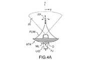
図1、図2、及び図3に示される本発明の実施形態による撮像・治療装置は、同心に配置され、球形ボウルSB上に位置合わせされた、半径が増大する環状超音波トランスデューサUT1〜UT5のアレイATAを備える。図示されない異なる実施形態によれば、トランスデューサは、凹形であるが、非球形(例えば、放物形)のボウルに配置してもよく、又は平面に配置してもよい。そのようなトランスデューサのアレイは、例えば、上記引用した文献である米国特許第5,520,188号明細書に記載されている。 The imaging and therapeutic devices according to the embodiments of the present invention shown in FIGS. 1, 2, and 3 are concentrically arranged and positioned on a spherical bowl SB and have an increasing radius, annular ultrasonic transducers UT1 to UT5. Array ATA is provided. According to different embodiments not shown, the transducer is concave, but may be placed in a non-spherical (eg, parabolic) bowl or may be placed in a flat surface. An array of such transducers is described, for example, in US Pat. No. 5,520,188, which is the cited document above.
5つのトランスデューサが図2及び図3に表されているが、異なる数、例えば、最高で数十までを使用してもよく、過度の複雑性を回避するために、5〜20に含まれる数が好ましい。環状トランスデューサは、好ましくは、図2に表されるように円形であり、より正確には、各環状トランスデューサは、円形ベースの直角円錐形切頭体の形状を有し得る。他の形状も可能である(例えば、楕円形、矩形・・・)。環状トランスデューサは、連続してもよく、又は離散したセグメントによって形成されてもよい。 Five transducers are shown in FIGS. 2 and 3, but different numbers, for example up to tens, may be used and are included in 5 to 20 to avoid excessive complexity. Is preferable. The annular transducers are preferably circular, as shown in FIG. 2, and more precisely, each annular transducer may have the shape of a circular-based right-angled conical frustum. Other shapes are possible (eg, oval, rectangular ...). The annular transducer may be continuous or may be formed by discrete segments.
米国特許第5,520,188号明細書及びR.M.Millerらによる上記引用した論文と同様に、超音波撮像装置UID−例えば、二次元、二平面、又は三次元超音波検査プローブ−は、最も内側のトランスデューサUT1内部のアレイATAの中心に配置される。 U.S. Pat. Nos. 5,520,188 and R.M. M. Similar to the above cited paper by Miller et al., The ultrasound imager UID-eg, a two-dimensional, two-planar, or three-dimensional ultrasound probe-is centered on the array ATA inside the innermost transducer UT1. ..
しかしながら、従来技術とは異なり、撮像装置はトランスデューサアレイATAに直接固定されず、機械的リンクMLを通してトランスデューサアレイATAに接続され、機械的リンクMLの可能な構造を図1及び図2に示す。機械的リンクMLにより、撮像装置UIDに対してトランスデューサアレイATAを傾斜させることができ、すなわち、少なくとも、撮像装置UIDの視軸Ozに直交する軸Oxの回りでトランスデューサアレイATAを回転させることができる。本発明の異なる実施形態によれば、機械的リンクMLにより、相互に直交するとともに、視軸Ozに直交する2つの軸Ox、Oyの回りでトランスデューサアレイATAを回転させることができる。好ましくは、旋回点Oは、トランスデューサアレイATAの凹形ボウルの中心に対応する。 However, unlike prior art, the image pickup device is not directly fixed to the transducer array ATA, but is connected to the transducer array ATA through a mechanical link ML, and the possible structures of the mechanical link ML are shown in FIGS. 1 and 2. The mechanical link ML allows the transducer array ATA to be tilted relative to the image pickup device UID, i.e., at least the transducer array ATA can be rotated about an axis Ox orthogonal to the visual axis Oz of the image pickup device UID. .. According to different embodiments of the present invention, the mechanical link ML allows the transducer array ATA to rotate around two axes, Ox, Oy, which are orthogonal to each other and orthogonal to the visual axis Oz. Preferably, the swivel point O corresponds to the center of the concave bowl of the transducer array ATA.
電気モータM1(図2のみに表される)は、リンクMLの回転自由度を作動させる。2自由度の実施形態では、通常、2つの独立したモータが提供される。 The electric motor M1 (represented only in FIG. 2) activates the rotational degrees of freedom of the link ML. In a two-degree-of-freedom embodiment, two independent motors are usually provided.
図1〜図3の実施形態では、機械的リンクMLは旋回継手に基づく。より正確には、機械的リンクMLは、
−撮像装置UIDが固定接続される固定枠F、及び
−モータM1により作動する軸Oxの旋回継手PJであって、枠Fに固定接続された固定子S1及びトランスデューサアレイに固定接続される回転子R1を備える、旋回継手PJを備える。In the embodiments of FIGS. 1 to 3, the mechanical link ML is based on a swivel joint. More precisely, the mechanical link ML
-A fixed frame F to which the image pickup device UID is fixedly connected, and-a rotor S1 fixedly connected to the frame F and a rotor fixedly connected to the transducer array, which is a swivel joint PJ of the shaft Ox operated by the motor M1. A swivel joint PJ with R1 is provided.
2自由度の実施形態では、リンクMLは、直交する軸を有し、直列接続された2つの旋回継手又はz軸回りの追加の、通常は不必要な回転自由度を提供する玉継手を含む自在継手含み得る。 In a two-degree-of-freedom embodiment, the link ML has two orthogonal axes and includes two swivel joints connected in series or a ball joint that provides an additional, usually unnecessary rotational degree of freedom around the z-axis. Can include universal joints.
図1及び図3において、トランスデューサアレイへの法線軸が、撮像装置の撮像軸Ozに対して角度αだけ傾斜することを見て取ることができ、撮像装置の撮像軸Ozは、患者の体Bの皮膚SKに略直交した状態を保つ。超音波トランスデューサUT1〜UT5により放射される超音波FUWは、z’軸上にある焦点FPにおいて集束する。トランスデューサアレイの球形(より一般的には凹形)の形状は、超音波が「幾何学的」又は「自然な」焦点距離で集束することを保証する。トランスデューサに供給される信号間に適する遅延を導入することにより得られる電子回路による集束は、焦点を複数の深さに移動させることができる。 In FIGS. 1 and 3, it can be seen that the normal axis to the transducer array is tilted by an angle α with respect to the image pickup axis Oz of the image pickup device, and the image pickup axis Oz of the image pickup device is the skin of the patient's body B. It keeps a state substantially orthogonal to SK. The ultrasonic FUW emitted by the ultrasonic transducers UT1 to UT5 is focused at the focal point FP on the z'axis. The spherical (more generally concave) shape of the transducer array ensures that the ultrasound is focused at a "geometric" or "natural" focal length. The focus by the electronic circuit obtained by introducing a suitable delay between the signals delivered to the transducer can shift the focus to multiple depths.
次に、焦点FPは、Oz’方向において、超音波トランスデューサの駆動信号の相対位相を変更することにより電子的にかつOzに直交する方向又は平面(実際には、直線により近似することができる円形セグメント若しくは球面又は傾斜角αが小さい場合、平面)においてトランスデューサアレイを傾斜させることにより機械的に操縦することができる。このように、焦点FPは、動かない撮像装置UIDからの常時監視下で、体Bの標的領域T内で二次元又は三次元経路SPに沿って操縦することができる。図1の例では、撮像装置UIDは2つの隣接する肋骨R間に位置決めされ、それにより、標的領域Tの高質画像を取得することができる。 Next, the focal point FP is a circle that is electronically and orthogonal to Oz (actually, can be approximated by a straight line) by changing the relative phase of the drive signal of the ultrasonic transducer in the Oz'direction. If the segment or sphere or tilt angle α is small, it can be mechanically steered by tilting the transducer array in a plane). In this way, the focal point FP can be steered along the two-dimensional or three-dimensional path SP within the target region T of the body B under constant monitoring from the stationary image pickup device UID. In the example of FIG. 1, the image pickup device UID is positioned between two adjacent ribs R, whereby a high quality image of the target region T can be obtained.
大半の用途で小さな傾斜角αが十分であることに留意することが興味深い。例えば、超音波FUWが患者の皮膚の5cm下の深さにおいて集束する場合、±6°未満の傾斜が、1cm幅標的領域のスキャンに十分である。本発明の異なる実施形態によれば、機械的リンクMLは、傾斜又は±10°又は±20°を可能にするのに十分であり得る。 It is interesting to note that a small tilt angle α is sufficient for most applications. For example, if the ultrasound FUW focuses at a depth of 5 cm below the patient's skin, an inclination of less than ± 6 ° is sufficient to scan the 1 cm wide target area. According to different embodiments of the invention, the mechanical link ML may be sufficient to allow tilting or ± 10 ° or ± 20 °.
撮像装置UIDが静止したままであり、患者の皮膚に直接又は間接的に接触した状態を保つ間(実際には「直接」の接触でさえ通常、超音波検査ゲルの薄層の介在を暗示する)、超音波トランスデューサUT1〜UT5は、超音波撮像装置がアレイから突出し、傾斜を可能にする自由空間を提供するため、できない。変形可能なゲル充填又は脱気水充填バッグGFB−恐らくは、撮像装置UIDと位置合わせされて中心に穴を有する−が、トランスデューサアレイATAと患者の皮膚との間に介在して、集束超音波の伝搬を可能にし得る。 While the imager UID remains stationary and in direct or indirect contact with the patient's skin (actually even "direct" contact usually implies the intervention of a thin layer of ultrasound gel. ), The ultrasonic transducers UT1 to UT5 are not possible because the ultrasonic image pickup device protrudes from the array and provides a free space that allows tilting. A deformable gel-filled or degassed water-filled bag GFB-perhaps aligned with the imager UID and having a central hole-intervenes between the transducer array ATA and the patient's skin to focus the ultrasound. May allow propagation.
図3では、参照ESGは、アレイATAの超音波トランスデューサの個々の駆動信号を生成する電子信号生成器を示す。信号は、焦点FPの軸方向位置(すなわち、Oz’軸に沿った位置)を決める可変位相シフトを用いて生成される。コントローラC−例えば、適宜プログラムされたコンピュータ又はマイクロコントローラ−は、リンクMLを作動して、焦点FPを操縦する電子信号生成器ESG及びモータM1(又は2自由度の実施形態では2つのモータ)を駆動する。コントローラは、撮像装置UIDから画像データを受信して、操縦を自動的に実行し得る。例えば、コントローラCは、焦点FPが、標的の生理学的運動を補償しながら同時に、所定の経路SPを辿って心臓の標的領域Tをスキャンするように電子信号生成器ESG及びモータM1を駆動し得る。適する運動補償アルゴリズムは、R.M.Millerらによる上記引用した論文及びM.Pernotら著“3−D real−time motion correction in high−intensity focused ultrasound therapy”Ultrasound in Med Biol 2004,30,9,1239−1249に記載されている。 In FIG. 3, the reference ESG shows an electronic signal generator that produces the individual drive signals of the ultrasonic transducers of the array ATA. The signal is generated using a variable phase shift that determines the axial position of the focal point FP (ie, the position along the Oz'axis). Controller C-for example, an appropriately programmed computer or microcontroller-is an electronic signal generator ESG and motor M1 (or two motors in a two-degree-of-freedom embodiment) that activates the link ML to steer the focal FP. Drive. The controller may receive image data from the image pickup device UID and automatically perform maneuvering. For example, the controller C may drive the electronic signal generator ESG and the motor M1 so that the focal FP compensates for the physiological movement of the target and at the same time follows a predetermined path SP to scan the target region T of the heart. .. Suitable motion compensation algorithms are R.M. M. The above-cited paper by Miller et al. And M. et al. It is described in Pernot et al., "3-D real-time ultrasound rotation in high-intensity focused ultrasound and therapy" Ultrasound in Med Biol 2004, 30, 9, 1239-1249.
有利なことに、コントローラは、焦点が標的領域外に移動したことを撮像装置からの画像データが示す場合、治療を即座に停止するように構成し得、それにより、心臓組織に損傷を負わすリスクを低減する。 Advantageously, the controller may be configured to stop treatment immediately if the image data from the imaging device indicates that the focus has moved out of the target area, thereby inflicting damage on the heart tissue. Reduce risk.
幾つかの実施形態では、コントローラは、撮像装置から受信した画像データを処理して、治療に関連する情報、例えば、キャビテーション活動インジケータをそこから抽出するように構成することもできる。次に、この情報を使用して、集束超音波の強度レベルを自動的に適合し得る。B.Arnalらによる論文“In vivo real−time cavitation imaging in moving organs”,Physics in Medicine & Biology 62,843−857(2017)には、中心に超音波撮像装置が設けられた凹形超音波トランスデューサにより放射される集束超音波により生成されるキャビテーション気泡を撮像する方法が記載されている。この方法によれば、超音波撮像装置は、一連の撮像パルスを放射し、2つの連続したキャビテーション誘導パルス間の対応するエコーを取得する。次に、エコーを処理して、周囲組織から区別されるキャビテーション気泡の画像を抽出する。キャビテーション気泡が検出されない場合、コントローラは、超音波力が不十分であると推測し、超音波力を上げる(好ましくは、人間オペレータの制御下で)。キャビテーション気泡が、予期される焦点よりもトランスデューサの近傍で検出される場合、コントローラは、超音波力が過剰であると推測し、超音波力を下げ得る。 In some embodiments, the controller can also be configured to process image data received from the imaging device to extract treatment-related information, such as cavitation activity indicators, from it. This information can then be used to automatically adapt the intensity level of the focused ultrasound. B. In the paper "In vivo real-time cavitation imaging in moving organs" by Arnal et al., Physics in Medicine & Biologic 62, 843-857 (2017), a concave ultrasound with an ultrasonic imager in the center. A method of imaging a cavitation bubble generated by focused ultrasound is described. According to this method, the ultrasonic imaging device emits a series of imaging pulses to obtain the corresponding echo between two consecutive cavitation induction pulses. The echo is then processed to extract an image of the cavitation bubble that is distinct from the surrounding tissue. If no cavitation bubbles are detected, the controller estimates that the ultrasonic force is inadequate and increases the ultrasonic force (preferably under the control of a human operator). If the cavitation bubble is detected closer to the transducer than expected, the controller may infer that the ultrasonic force is excessive and reduce the ultrasonic force.
本発明の例示的な実施形態では、撮像・治療装置は、半径が以下の表1に列挙される、球形ボウルに配置された12個の環状超音波トランスデューサを備える。 In an exemplary embodiment of the invention, the imaging and treatment apparatus comprises twelve annular ultrasonic transducers arranged in a spherical bowl whose radii are listed in Table 1 below.

そのようなアレイは、「自然」な焦点距離110mm(球形ボウルSBの半径に対応する)を有し、焦点距離は、40mm〜180mmで電子的に調整し得る。患者に接触した、固定された撮像トランスデューサにより、撮像トランスデューサの固定に起因した損失が限定的である状態で、±20°のトランスデューサ傾斜が可能なことが分かっている。焦点深度と傾斜値との組み合わせにより、そのようなトランスデューサアレイは焦点を±66mm、横方向に移動させることができる。そのようなトランスデューサアレイを治療に使用すると、2自由度リンクを用いる場合、患者から撮像トランスデューサを変位させずに、810立方cmを超える体積を焦点により掃引し得る。この実施形態では、ステッパモータが2つの回転軸(Ox、Oy)のそれぞれに直接搭載されて、トランスデューサアレイを機械的に傾斜させる。200Hzで駆動される200ステップを有するそのようなステッパモータは、0.3mm/ms〜20mm/msの範囲の速度で焦点を機械的に移動させることができる。 Such an array has a "natural" focal length of 110 mm (corresponding to the radius of the spherical bowl SB), the focal length of which can be electronically adjusted from 40 mm to 180 mm. It has been found that a fixed imaging transducer in contact with a patient allows a transducer tilt of ± 20 ° with limited loss due to fixation of the imaging transducer. Depending on the combination of depth of focus and tilt value, such a transducer array can move the focal point laterally by ± 66 mm. When such a transducer array is used therapeutically, when using a two-degree-of-freedom link, a volume greater than 810 cubic cm can be swept by focus without displacing the image transducer from the patient. In this embodiment, a stepper motor is mounted directly on each of the two axes of rotation (Ox, Oy) to mechanically tilt the transducer array. Such stepper motors with 200 steps driven at 200 Hz can mechanically move the focus at speeds in the range of 0.3 mm / ms to 20 mm / ms.
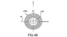
図4A及び図4Bは、超音波撮像装置UIDが、略平坦であり、yz平面(撮像面)にある撮像領域IRを画定する二次元超音波検査プローブである実施形態を示す。超音波トランスデューサのアレイATAは、軸Oxの回りを回転可能なように搭載される。Oz軸に沿った電子的な操縦及びOx軸の回りのアレイATAの傾斜により、平坦な撮像領域IR内で焦点FP(実際には、有限体積の領域であり、Oz’に沿って長尺形を有する)を変位させることができる。 4A and 4B show an embodiment in which the ultrasonic imaging device UID is a two-dimensional ultrasonic inspection probe that is substantially flat and defines an imaging region IR in the yz plane (imaging surface). The array ATA of the ultrasonic transducer is mounted so as to be rotatable around the axis Ox. Due to electronic maneuvering along the Oz axis and tilting of the array ATA around the Ox axis, the focal FP (actually a finite volume region, elongated along Oz') within the flat imaging region IR. Can be displaced.
図5A及び図5Bは、超音波撮像装置UIDが、略平坦であり、それぞれyz平面及びxz平面(撮像面)にある2つのサブ領域IR1及びIR2により構成される撮像領域を画定する二方面超音波検査プローブである別の実施形態を示す。超音波トランスデューサのアレイATAは、軸Ox及びOyの回りを回転可能なように搭載される。Oz’軸に沿った電子的な操縦並びにOx軸及びOy軸の回りのアレイATAの傾斜により、2つの平坦撮像領域IR1及びIR2内で焦点FP(実際には、有限体積の領域であり、Oz’に沿って長尺形を有する)を変位させることができる。 In FIGS. 5A and 5B, the ultrasonic image pickup device UID is substantially flat and defines an image pickup region composed of two sub-regions IR1 and IR2 in the yz plane and the xz plane (imaging plane), respectively. Another embodiment of the ultrasound probe is shown. The array ATA of the ultrasonic transducer is mounted so as to be rotatable around the axes Ox and Oy. Due to electronic maneuvering along the Oz'axis and tilting of the array ATA around the Ox and Oy axes, the focal FP (actually a finite volume region, Oz) within the two flat imaging regions IR1 and IR2. (Has a long shape along the') can be displaced.
図示されない本発明の更に別の実施形態によれば、超音波撮像装置UIDは、Oz軸を全て含む無限に多くの撮像平面を含む完全な三次元領域を画定する三次元行列超音波検査プローブである。超音波トランスデューサのアレイATAは、軸Ox及びOyの回りを回転可能なように搭載される。Oz’軸に沿った電子的な操縦並びにOx軸及びOy軸の回りのアレイATAの傾斜により、三次元撮像領域内で焦点FP(実際には、有限体積の領域であり、Oz’に沿って長尺形を有する)を変位させることができる。 According to yet another embodiment of the invention (not shown), the ultrasound imaging device UID is a three-dimensional matrix ultrasound examination probe that defines a complete three-dimensional region containing an infinite number of imaging planes including all Oz axes. be. The array ATA of the ultrasonic transducer is mounted so as to be rotatable around the axes Ox and Oy. Due to electronic maneuvering along the Oz'axis and tilting of the array ATA around the Ox and Oy axes, the focal FP (actually a finite volume region, along Oz' within the 3D imaging region. (Has a long shape) can be displaced.
上述したように、トランスデューサは、適する電子回路ESGにより駆動されて、超音波を生成する。1つの可能な駆動回路ESGは、各環状トランスデューサで時間遅延信号を生成するパルス電力増幅器である。本発明の特定の実施形態では、100kHz〜4MHz、好ましくは500kHz〜1MHzの範囲の中心周波数における1組の正弦周期がトランスデューサに適用される。バーストと呼ばれるこの1組の正弦周期は、0.01Hz〜1000Hzの範囲のパルス反復周波数(PRF)として既知の一定の周波数で繰り返される。本発明では、バーストの長さは1μsから最高で100msの範囲である。砕石又は細胞破砕等の衝撃波ベースの用途では、生成される超音波の振幅は、焦点における生物組織にキャビテーションを誘導するのに十分なものであるべきである。これは、焦点において生成されるピーク正圧が、少なくとも10MPa、好ましくは少なくとも50MPaであるべきであり、ピーク負圧が少なくとも−5MPa、好ましくは少なくとも−10MPaであるべきであることを意味する。 As mentioned above, the transducer is driven by a suitable electronic circuit ESG to generate ultrasonic waves. One possible drive circuit ESG is a pulsed power amplifier that produces a time delay signal at each annular transducer. In certain embodiments of the invention, a set of sinusoidal periods at a center frequency in the range of 100 kHz to 4 MHz, preferably 500 kHz to 1 MHz is applied to the transducer. This set of sine periods, called bursts, is repeated at a constant frequency known as the pulse repetition frequency (PRF) in the range 0.01 Hz to 1000 Hz. In the present invention, the burst length ranges from 1 μs up to 100 ms. For shock wave based applications such as crushed stone or cell crushing, the amplitude of the generated ultrasonic waves should be sufficient to induce cavitation in the biological tissue at the focal point. This means that the peak positive pressure generated at the focal point should be at least 10 MPa, preferably at least 50 MPa, and the peak negative pressure should be at least -5 MPa, preferably at least -10 MPa.
本発明の装置は、様々な医療用途に役立つ。心臓病学では、本発明の装置により、僧帽弁腱索を切断して、僧帽弁逆流を治療し、心臓弁を軟化させて、弁狭窄を治療し、心臓内連通等が可能になる。本発明の装置は、非心臓用途、すなわち、腎臓結石、血管石灰化、腫瘍の焼灼にも適する。本発明の装置は特に、非侵襲的な用途に適するが、侵襲的に使用することもでき、例えば、胸骨切開後に心膜に使用することもできる。本発明の装置は、超音波ソノポレーション又は心臓疾患の制御された薬剤治療での心臓における治療薬剤の薬剤送達に使用することもできる。 The device of the present invention is useful for various medical applications. In cardiology, the device of the present invention enables cutting of the mitral valve chordae tendineae to treat mitral valve regurgitation, softening the heart valve, treating valve stenosis, intracardiac communication, etc. .. The apparatus of the present invention is also suitable for non-cardiac applications, ie kidney stones, vascular calcification, tumor ablation. The device of the present invention is particularly suitable for non-invasive applications, but can also be used invasively, for example, for the pericardium after a sternotomy. The device of the present invention can also be used for drug delivery of therapeutic agents in the heart in ultrasonic sonoporation or controlled drug treatment of heart disease.
Claims (15)
Translated fromJapanese前記複数の同心環状超音波トランスデューサの最も内側のトランスデューサ内部に配置される超音波撮像装置(UID)
を備える超音波撮像及び治療装置であって、
前記超音波撮像装置に対する前記同心環状超音波トランスデューサのアレイの傾斜移動を可能にする機械的リンク(ML)を更に備え、前記超音波撮像装置が、前記同心環状超音波トランスデューサのアレイにおける超音波の伝搬方向でいう最も前方のアレイを超えて、超音波の伝搬方向の前方に延びること
を特徴とし、
それにより、前記同心環状超音波トランスデューサのアレイ(ATA)が傾斜して、前記同心環状超音波トランスデューサにより生成される超音波の焦点を前記超音波撮像装置の撮像領域(IR、IR1、IR2)内で移動させる間、前記超音波撮像装置(UID)は、静止したままであり、患者の皮膚に直接又は間接的に接触したままであることができる、超音波撮像及び治療装置。An array (ATA) of concentric annular ultrasonic transducers (UT1 to UT5), and an ultrasonic image pickup device (UID) arranged inside the innermost transducers of the plurality of concentric annular ultrasonic transducers.
It is an ultrasonic imaging and treatment device equipped with
Said mechanical link (ML) furtherexample Bei a to enable tilting movement of the array of concentric annular ultrasonic transducer for ultrasonic imagingapparatus, before Symbol ultrasonic imaging apparatus, the concentric annular ultrasound transducingsub array It is characterizedby extending beyond the foremost array in the propagation direction of ultrasonic waves in the above direction and in front of the propagation direction of ultrasonic waves.
As a result, the array (ATA) of the concentric annular ultrasonic transducer is tilted, and the focus of the ultrasonic wave generated by the concentric annular ultrasonic transducer is focused in the imaging region (IR, IR1, IR2) of the ultrasonic imaging device. The ultrasound imaging and treatment device, wherein the ultrasound imaging device (UID) remains stationary and can remain in direct or indirect contact with the patient's skin while being moved in.
Applications Claiming Priority (3)
| Application Number | Priority Date | Filing Date | Title |
|---|---|---|---|
| EP16305472.9AEP3236467A1 (en) | 2016-04-22 | 2016-04-22 | Ultrasound imaging and therapy device |
| EP16305472.9 | 2016-04-22 | ||
| PCT/EP2017/059556WO2017182655A1 (en) | 2016-04-22 | 2017-04-21 | Ultrasound imaging and therapy device |
Publications (2)
| Publication Number | Publication Date |
|---|---|
| JP2019514485A JP2019514485A (en) | 2019-06-06 |
| JP6980696B2true JP6980696B2 (en) | 2021-12-15 |
Family
ID=55854747
Family Applications (1)
| Application Number | Title | Priority Date | Filing Date |
|---|---|---|---|
| JP2018555162AActiveJP6980696B2 (en) | 2016-04-22 | 2017-04-21 | Ultrasound imaging and treatment equipment |
Country Status (8)
| Country | Link |
|---|---|
| US (1) | US11554386B2 (en) |
| EP (2) | EP3236467A1 (en) |
| JP (1) | JP6980696B2 (en) |
| KR (1) | KR102427579B1 (en) |
| CN (1) | CN109416907B (en) |
| CA (1) | CA3021814A1 (en) |
| IL (1) | IL262354B2 (en) |
| WO (1) | WO2017182655A1 (en) |
Cited By (5)
| Publication number | Priority date | Publication date | Assignee | Title |
|---|---|---|---|---|
| US11648424B2 (en) | 2018-11-28 | 2023-05-16 | Histosonics Inc. | Histotripsy systems and methods |
| US11813485B2 (en) | 2020-01-28 | 2023-11-14 | The Regents Of The University Of Michigan | Systems and methods for histotripsy immunosensitization |
| US12220602B2 (en) | 2015-06-24 | 2025-02-11 | The Regents Of The University Of Michigan | Histotripsy therapy systems and methods for the treatment of brain tissue |
| US12318636B2 (en) | 2022-10-28 | 2025-06-03 | Histosonics, Inc. | Histotripsy systems and methods |
| US12343568B2 (en) | 2020-08-27 | 2025-07-01 | The Regents Of The University Of Michigan | Ultrasound transducer with transmit-receive capability for histotripsy |
Families Citing this family (18)
| Publication number | Priority date | Publication date | Assignee | Title |
|---|---|---|---|---|
| FR3081334B1 (en) | 2018-05-25 | 2020-05-01 | Cardiawave Sa | ULTRASONIC TREATMENT APPARATUS COMPRISING MEANS OF IMAGING CAVITATION BUBBLES |
| US11065643B2 (en)* | 2018-08-17 | 2021-07-20 | Acoustiic Inc. | Ultrasonic imaging and energy delivery device and method |
| KR102117485B1 (en)* | 2018-09-14 | 2020-06-02 | 재단법인 대구경북첨단의료산업진흥재단 | Ultrasound stimulator having multiple channel |
| US11311454B2 (en)* | 2019-03-28 | 2022-04-26 | Softwave Tissue Regeneration Technologies, Llc | Handheld acoustic shock wave or pressure pulse application device and methods of use |
| CN110559565B (en)* | 2019-10-16 | 2024-12-10 | 无锡海鹰医疗科技股份有限公司 | Ultrasonic spherical surface scanning three-dimensional body treatment device and use method thereof |
| CN110732097A (en)* | 2019-10-17 | 2020-01-31 | 中科绿谷(深圳)医疗科技有限公司 | Ultrasonic transducer adjustment mechanism and ultrasonic therapeutic apparatus |
| WO2021081105A1 (en) | 2019-10-21 | 2021-04-29 | University Of Virginia Patent Foundation | Methods, systems, and computer readable media for utilizing a therapeutic ultrasound device to perform mitral valve decalcification |
| CN111134776B (en)* | 2020-01-10 | 2025-08-08 | 深圳市奥昇医疗科技有限责任公司 | High-intensity focused ultrasound device and control method |
| IL311310B2 (en)* | 2020-03-05 | 2025-05-01 | Exo Imaging Inc | Ultrasonic imaging device with programmable anatomy and flow imaging |
| KR102610342B1 (en) | 2020-08-13 | 2023-12-07 | 한국과학기술연구원 | Flexible ultrasound transducer and method for manufacturing the same |
| CN112245818B (en)* | 2020-09-09 | 2022-05-17 | 深圳先进技术研究院 | Ultrasound neuromodulation device |
| EP4216824A1 (en)* | 2020-09-29 | 2023-08-02 | Bard Access Systems, Inc. | Hands-free ultrasound probes, assemblies, systems, and methods |
| CN113101551A (en)* | 2021-05-12 | 2021-07-13 | 北京小超科技有限公司 | Ultrasonic treatment probe for breast tumor and device comprising same |
| CN113288499A (en)* | 2021-06-18 | 2021-08-24 | 中惠医疗科技(上海)有限公司 | Focused ultrasound platform for small animal experiments |
| KR102490676B1 (en)* | 2021-09-30 | 2023-01-27 | 주식회사 소노티엑스 | Therapy Devices and Methods Using Ultrasound |
| IL291793B2 (en)* | 2022-03-29 | 2023-12-01 | Ilan Feferberg | Tiltingly oscillating ultrasound treatment device |
| EP4445859A1 (en)* | 2023-04-12 | 2024-10-16 | Commissariat à l'Energie Atomique et aux Energies Alternatives | Focused ultrasound sonication with mechanical and electronic steering along a computed trajectory |
| KR102739401B1 (en)* | 2023-11-24 | 2024-12-09 | (주)아이엠지티 | Focused ultrasound processing apparatus and method for delivering drug using the same |
Family Cites Families (13)
| Publication number | Priority date | Publication date | Assignee | Title |
|---|---|---|---|---|
| DE3932364A1 (en)* | 1989-09-28 | 1991-04-11 | Wolf Gmbh Richard | DEVICE FOR SPACIOUS LOCATION AND DESTRUCTION OF INTERIOR OBJECTS |
| JP3386488B2 (en)* | 1992-03-10 | 2003-03-17 | 株式会社東芝 | Ultrasound therapy equipment |
| JPH06105851A (en)* | 1992-09-30 | 1994-04-19 | Toshiba Corp | Ultrasonic therapy equipment |
| US5520188A (en) | 1994-11-02 | 1996-05-28 | Focus Surgery Inc. | Annular array transducer |
| DE19507478C1 (en)* | 1995-03-03 | 1996-05-15 | Siemens Ag | Therapy device for treatment with focused ultrasound |
| JP4131580B2 (en)* | 1997-12-05 | 2008-08-13 | 株式会社東芝 | Ultrasonic therapy device |
| EP2091438B1 (en)* | 2006-11-28 | 2012-01-11 | Koninklijke Philips Electronics N.V. | Apparatus for 3d ultrasound imaging and therapy |
| US8466605B2 (en) | 2008-03-13 | 2013-06-18 | Ultrashape Ltd. | Patterned ultrasonic transducers |
| US8295912B2 (en)* | 2009-10-12 | 2012-10-23 | Kona Medical, Inc. | Method and system to inhibit a function of a nerve traveling with an artery |
| JP5933549B2 (en)* | 2010-08-18 | 2016-06-08 | ミラビリス メディカ インク | HIFU applicator |
| JP2012050516A (en)* | 2010-08-31 | 2012-03-15 | Fujifilm Corp | Portable ultrasonic diagnostic apparatus |
| JP5775751B2 (en)* | 2011-06-15 | 2015-09-09 | オリンパス株式会社 | Ultrasonic irradiation device |
| EP3074090B1 (en)* | 2014-02-10 | 2017-11-22 | St. Jude Medical, Cardiology Division, Inc. | Device for ablation and photoacoustics imaging |
- 2016
- 2016-04-22EPEP16305472.9Apatent/EP3236467A1/ennot_activeWithdrawn
- 2017
- 2017-04-21CACA3021814Apatent/CA3021814A1/enactivePending
- 2017-04-21JPJP2018555162Apatent/JP6980696B2/enactiveActive
- 2017-04-21EPEP17718103.9Apatent/EP3446306B1/enactiveActive
- 2017-04-21ILIL262354Apatent/IL262354B2/enunknown
- 2017-04-21USUS16/095,304patent/US11554386B2/enactiveActive
- 2017-04-21WOPCT/EP2017/059556patent/WO2017182655A1/ennot_activeCeased
- 2017-04-21KRKR1020187030181Apatent/KR102427579B1/enactiveActive
- 2017-04-21CNCN201780024987.2Apatent/CN109416907B/enactiveActive
Cited By (9)
| Publication number | Priority date | Publication date | Assignee | Title |
|---|---|---|---|---|
| US12220602B2 (en) | 2015-06-24 | 2025-02-11 | The Regents Of The University Of Michigan | Histotripsy therapy systems and methods for the treatment of brain tissue |
| US11648424B2 (en) | 2018-11-28 | 2023-05-16 | Histosonics Inc. | Histotripsy systems and methods |
| US11813484B2 (en) | 2018-11-28 | 2023-11-14 | Histosonics, Inc. | Histotripsy systems and methods |
| US11980778B2 (en) | 2018-11-28 | 2024-05-14 | Histosonics, Inc. | Histotripsy systems and methods |
| US12420118B2 (en) | 2018-11-28 | 2025-09-23 | Histosonics, Inc. | Histotripsy systems and methods |
| US11813485B2 (en) | 2020-01-28 | 2023-11-14 | The Regents Of The University Of Michigan | Systems and methods for histotripsy immunosensitization |
| US12343568B2 (en) | 2020-08-27 | 2025-07-01 | The Regents Of The University Of Michigan | Ultrasound transducer with transmit-receive capability for histotripsy |
| US12318636B2 (en) | 2022-10-28 | 2025-06-03 | Histosonics, Inc. | Histotripsy systems and methods |
| US12390665B1 (en) | 2022-10-28 | 2025-08-19 | Histosonics, Inc. | Histotripsy systems and methods |
Also Published As
| Publication number | Publication date |
|---|---|
| EP3446306A1 (en) | 2019-02-27 |
| IL262354B2 (en) | 2023-03-01 |
| CA3021814A1 (en) | 2017-10-26 |
| JP2019514485A (en) | 2019-06-06 |
| US20190126317A1 (en) | 2019-05-02 |
| EP3446306B1 (en) | 2024-11-20 |
| WO2017182655A1 (en) | 2017-10-26 |
| KR102427579B1 (en) | 2022-08-01 |
| CN109416907A (en) | 2019-03-01 |
| EP3446306C0 (en) | 2024-11-20 |
| US11554386B2 (en) | 2023-01-17 |
| EP3236467A1 (en) | 2017-10-25 |
| CN109416907B (en) | 2023-10-31 |
| IL262354B (en) | 2022-11-01 |
| IL262354A (en) | 2018-11-29 |
| KR20190004701A (en) | 2019-01-14 |
Similar Documents
| Publication | Publication Date | Title |
|---|---|---|
| JP6980696B2 (en) | Ultrasound imaging and treatment equipment | |
| Hynynen et al. | Image-guided ultrasound phased arrays are a disruptive technology for non-invasive therapy | |
| US20110144544A1 (en) | Ultrasound transducer assembly and methods of using | |
| EP2470267B1 (en) | Micromanipulator control arm for therapeutic and imaging ultrasound transducers | |
| EP2334375B1 (en) | System for ultrasound therapy treatment | |
| EP1633266B1 (en) | Apparatus for treating atrial fibrillation using high intensity focused ultrasound | |
| US20050015024A1 (en) | Ultrasonic method and device for lypolytic therapy | |
| US20100042020A1 (en) | Focused energy delivery apparatus method and system | |
| US20150343243A1 (en) | Method and system for noninvasive mastopexy | |
| US20050165298A1 (en) | Treatment of cardiac tissue following myocardial infarction utilizing high intensity focused ultrasound | |
| US20100274161A1 (en) | Implosion techniques for ultrasound | |
| JP4434668B2 (en) | Treatment system and treatment support system | |
| JP2023111991A (en) | Novel devices for transfection and drug delivery | |
| EP2699316A1 (en) | Transoesophageal device using high intensity focused ultrasounds for cardiac thermal ablation | |
| JPH11164837A (en) | Ultrasound therapy equipment | |
| JP2018082934A (en) | Ultrasound catheter for kidney nerve | |
| Yasui et al. | Focused ultrasonic device for sonodynamic therapy in the human body | |
| Rivens et al. | Imaged-Guided Focused Ultrasound Therapy: Physics and Clinical Applications | |
| CN120661856A (en) | A focused ultrasound tissue fragmentation system and method of use | |
| HK40008492A (en) | A novel transfection and drug delivery device |
Legal Events
| Date | Code | Title | Description |
|---|---|---|---|
| A621 | Written request for application examination | Free format text:JAPANESE INTERMEDIATE CODE: A621 Effective date:20200305 | |
| A977 | Report on retrieval | Free format text:JAPANESE INTERMEDIATE CODE: A971007 Effective date:20201207 | |
| A131 | Notification of reasons for refusal | Free format text:JAPANESE INTERMEDIATE CODE: A131 Effective date:20201222 | |
| A601 | Written request for extension of time | Free format text:JAPANESE INTERMEDIATE CODE: A601 Effective date:20210311 | |
| A521 | Request for written amendment filed | Free format text:JAPANESE INTERMEDIATE CODE: A523 Effective date:20210618 | |
| A131 | Notification of reasons for refusal | Free format text:JAPANESE INTERMEDIATE CODE: A131 Effective date:20210713 | |
| A521 | Request for written amendment filed | Free format text:JAPANESE INTERMEDIATE CODE: A523 Effective date:20211008 | |
| TRDD | Decision of grant or rejection written | ||
| A01 | Written decision to grant a patent or to grant a registration (utility model) | Free format text:JAPANESE INTERMEDIATE CODE: A01 Effective date:20211026 | |
| A61 | First payment of annual fees (during grant procedure) | Free format text:JAPANESE INTERMEDIATE CODE: A61 Effective date:20211117 | |
| R150 | Certificate of patent or registration of utility model | Ref document number:6980696 Country of ref document:JP Free format text:JAPANESE INTERMEDIATE CODE: R150 | |
| R250 | Receipt of annual fees | Free format text:JAPANESE INTERMEDIATE CODE: R250 |