JP6978599B2 - Fixation system and method for fixing sutures in preformed drill holes - Google Patents
Fixation system and method for fixing sutures in preformed drill holesDownload PDFInfo
- Publication number
- JP6978599B2 JP6978599B2JP2020523232AJP2020523232AJP6978599B2JP 6978599 B2JP6978599 B2JP 6978599B2JP 2020523232 AJP2020523232 AJP 2020523232AJP 2020523232 AJP2020523232 AJP 2020523232AJP 6978599 B2JP6978599 B2JP 6978599B2
- Authority
- JP
- Japan
- Prior art keywords
- suture
- anchor
- anchor body
- distal
- eyelet
- Prior art date
- Legal status (The legal status is an assumption and is not a legal conclusion. Google has not performed a legal analysis and makes no representation as to the accuracy of the status listed.)
- Active
Links
- 238000000034methodMethods0.000titledescription16
- 239000007943implantSubstances0.000claimsdescription46
- 238000003780insertionMethods0.000claimsdescription16
- 230000037431insertionEffects0.000claimsdescription16
- 230000007704transitionEffects0.000claimsdescription6
- 238000004891communicationMethods0.000claimsdescription2
- 239000012530fluidSubstances0.000claimsdescription2
- 210000000988bone and boneAnatomy0.000description28
- 210000004872soft tissueAnatomy0.000description18
- 230000008439repair processEffects0.000description15
- 238000005530etchingMethods0.000description11
- 210000001519tissueAnatomy0.000description7
- 208000034693LacerationDiseases0.000description5
- 230000007246mechanismEffects0.000description5
- 230000001419dependent effectEffects0.000description4
- 210000003127kneeAnatomy0.000description3
- 210000000513rotator cuffAnatomy0.000description3
- 230000008878couplingEffects0.000description2
- 238000010168coupling processMethods0.000description2
- 238000005859coupling reactionMethods0.000description2
- 239000000463materialSubstances0.000description2
- 239000000203mixtureSubstances0.000description2
- 238000001356surgical procedureMethods0.000description2
- 206010055082Lip injuryDiseases0.000description1
- 210000003423ankleAnatomy0.000description1
- 210000001217buttockAnatomy0.000description1
- 210000000845cartilageAnatomy0.000description1
- 210000004439collateral ligamentAnatomy0.000description1
- 230000006378damageEffects0.000description1
- 230000007547defectEffects0.000description1
- 210000002683footAnatomy0.000description1
- 238000009472formulationMethods0.000description1
- 210000001624hipAnatomy0.000description1
- 210000004394hip jointAnatomy0.000description1
- 210000002758humerusAnatomy0.000description1
- 238000002513implantationMethods0.000description1
- 230000005499meniscusEffects0.000description1
- 230000000149penetrating effectEffects0.000description1
- 230000002265preventionEffects0.000description1
- 230000008569processEffects0.000description1
- 230000008707rearrangementEffects0.000description1
- 210000003189scaphoid boneAnatomy0.000description1
- 210000000323shoulder jointAnatomy0.000description1
- 239000003356suture materialSubstances0.000description1
- 210000002435tendonAnatomy0.000description1
- 230000000451tissue damageEffects0.000description1
- 231100000827tissue damageToxicity0.000description1
- 230000017423tissue regenerationEffects0.000description1
Images


Classifications
- A—HUMAN NECESSITIES
- A61—MEDICAL OR VETERINARY SCIENCE; HYGIENE
- A61B—DIAGNOSIS; SURGERY; IDENTIFICATION
- A61B17/00—Surgical instruments, devices or methods
- A61B17/04—Surgical instruments, devices or methods for suturing wounds; Holders or packages for needles or suture materials
- A61B17/0401—Suture anchors, buttons or pledgets, i.e. means for attaching sutures to bone, cartilage or soft tissue; Instruments for applying or removing suture anchors
- A—HUMAN NECESSITIES
- A61—MEDICAL OR VETERINARY SCIENCE; HYGIENE
- A61F—FILTERS IMPLANTABLE INTO BLOOD VESSELS; PROSTHESES; DEVICES PROVIDING PATENCY TO, OR PREVENTING COLLAPSING OF, TUBULAR STRUCTURES OF THE BODY, e.g. STENTS; ORTHOPAEDIC, NURSING OR CONTRACEPTIVE DEVICES; FOMENTATION; TREATMENT OR PROTECTION OF EYES OR EARS; BANDAGES, DRESSINGS OR ABSORBENT PADS; FIRST-AID KITS
- A61F2/00—Filters implantable into blood vessels; Prostheses, i.e. artificial substitutes or replacements for parts of the body; Appliances for connecting them with the body; Devices providing patency to, or preventing collapsing of, tubular structures of the body, e.g. stents
- A61F2/02—Prostheses implantable into the body
- A61F2/08—Muscles; Tendons; Ligaments
- A61F2/0811—Fixation devices for tendons or ligaments
- A—HUMAN NECESSITIES
- A61—MEDICAL OR VETERINARY SCIENCE; HYGIENE
- A61B—DIAGNOSIS; SURGERY; IDENTIFICATION
- A61B17/00—Surgical instruments, devices or methods
- A61B17/04—Surgical instruments, devices or methods for suturing wounds; Holders or packages for needles or suture materials
- A61B17/0401—Suture anchors, buttons or pledgets, i.e. means for attaching sutures to bone, cartilage or soft tissue; Instruments for applying or removing suture anchors
- A61B2017/0409—Instruments for applying suture anchors
- A—HUMAN NECESSITIES
- A61—MEDICAL OR VETERINARY SCIENCE; HYGIENE
- A61B—DIAGNOSIS; SURGERY; IDENTIFICATION
- A61B17/00—Surgical instruments, devices or methods
- A61B17/04—Surgical instruments, devices or methods for suturing wounds; Holders or packages for needles or suture materials
- A61B17/0401—Suture anchors, buttons or pledgets, i.e. means for attaching sutures to bone, cartilage or soft tissue; Instruments for applying or removing suture anchors
- A61B2017/0412—Suture anchors, buttons or pledgets, i.e. means for attaching sutures to bone, cartilage or soft tissue; Instruments for applying or removing suture anchors having anchoring barbs or pins extending outwardly from suture anchor body
- A—HUMAN NECESSITIES
- A61—MEDICAL OR VETERINARY SCIENCE; HYGIENE
- A61B—DIAGNOSIS; SURGERY; IDENTIFICATION
- A61B17/00—Surgical instruments, devices or methods
- A61B17/04—Surgical instruments, devices or methods for suturing wounds; Holders or packages for needles or suture materials
- A61B17/0401—Suture anchors, buttons or pledgets, i.e. means for attaching sutures to bone, cartilage or soft tissue; Instruments for applying or removing suture anchors
- A61B2017/0414—Suture anchors, buttons or pledgets, i.e. means for attaching sutures to bone, cartilage or soft tissue; Instruments for applying or removing suture anchors having a suture-receiving opening, e.g. lateral opening
- A—HUMAN NECESSITIES
- A61—MEDICAL OR VETERINARY SCIENCE; HYGIENE
- A61B—DIAGNOSIS; SURGERY; IDENTIFICATION
- A61B17/00—Surgical instruments, devices or methods
- A61B17/04—Surgical instruments, devices or methods for suturing wounds; Holders or packages for needles or suture materials
- A61B17/0401—Suture anchors, buttons or pledgets, i.e. means for attaching sutures to bone, cartilage or soft tissue; Instruments for applying or removing suture anchors
- A61B2017/0427—Suture anchors, buttons or pledgets, i.e. means for attaching sutures to bone, cartilage or soft tissue; Instruments for applying or removing suture anchors having anchoring barbs or pins extending outwardly from the anchor body
- A—HUMAN NECESSITIES
- A61—MEDICAL OR VETERINARY SCIENCE; HYGIENE
- A61B—DIAGNOSIS; SURGERY; IDENTIFICATION
- A61B17/00—Surgical instruments, devices or methods
- A61B17/04—Surgical instruments, devices or methods for suturing wounds; Holders or packages for needles or suture materials
- A61B17/0401—Suture anchors, buttons or pledgets, i.e. means for attaching sutures to bone, cartilage or soft tissue; Instruments for applying or removing suture anchors
- A61B2017/044—Suture anchors, buttons or pledgets, i.e. means for attaching sutures to bone, cartilage or soft tissue; Instruments for applying or removing suture anchors with a threaded shaft, e.g. screws
- A—HUMAN NECESSITIES
- A61—MEDICAL OR VETERINARY SCIENCE; HYGIENE
- A61B—DIAGNOSIS; SURGERY; IDENTIFICATION
- A61B17/00—Surgical instruments, devices or methods
- A61B17/04—Surgical instruments, devices or methods for suturing wounds; Holders or packages for needles or suture materials
- A61B17/0401—Suture anchors, buttons or pledgets, i.e. means for attaching sutures to bone, cartilage or soft tissue; Instruments for applying or removing suture anchors
- A61B2017/0445—Suture anchors, buttons or pledgets, i.e. means for attaching sutures to bone, cartilage or soft tissue; Instruments for applying or removing suture anchors cannulated, e.g. with a longitudinal through-hole for passage of an instrument
- A—HUMAN NECESSITIES
- A61—MEDICAL OR VETERINARY SCIENCE; HYGIENE
- A61B—DIAGNOSIS; SURGERY; IDENTIFICATION
- A61B17/00—Surgical instruments, devices or methods
- A61B17/04—Surgical instruments, devices or methods for suturing wounds; Holders or packages for needles or suture materials
- A61B17/0401—Suture anchors, buttons or pledgets, i.e. means for attaching sutures to bone, cartilage or soft tissue; Instruments for applying or removing suture anchors
- A61B2017/0446—Means for attaching and blocking the suture in the suture anchor
- A61B2017/0448—Additional elements on or within the anchor
- A—HUMAN NECESSITIES
- A61—MEDICAL OR VETERINARY SCIENCE; HYGIENE
- A61B—DIAGNOSIS; SURGERY; IDENTIFICATION
- A61B17/00—Surgical instruments, devices or methods
- A61B17/04—Surgical instruments, devices or methods for suturing wounds; Holders or packages for needles or suture materials
- A61B2017/0496—Surgical instruments, devices or methods for suturing wounds; Holders or packages for needles or suture materials for tensioning sutures
- A—HUMAN NECESSITIES
- A61—MEDICAL OR VETERINARY SCIENCE; HYGIENE
- A61F—FILTERS IMPLANTABLE INTO BLOOD VESSELS; PROSTHESES; DEVICES PROVIDING PATENCY TO, OR PREVENTING COLLAPSING OF, TUBULAR STRUCTURES OF THE BODY, e.g. STENTS; ORTHOPAEDIC, NURSING OR CONTRACEPTIVE DEVICES; FOMENTATION; TREATMENT OR PROTECTION OF EYES OR EARS; BANDAGES, DRESSINGS OR ABSORBENT PADS; FIRST-AID KITS
- A61F2/00—Filters implantable into blood vessels; Prostheses, i.e. artificial substitutes or replacements for parts of the body; Appliances for connecting them with the body; Devices providing patency to, or preventing collapsing of, tubular structures of the body, e.g. stents
- A61F2/02—Prostheses implantable into the body
- A61F2/08—Muscles; Tendons; Ligaments
- A61F2/0811—Fixation devices for tendons or ligaments
- A61F2002/0847—Mode of fixation of anchor to tendon or ligament
- A61F2002/0852—Fixation of a loop or U-turn, e.g. eyelets, anchor having multiple holes
Landscapes
- Health & Medical Sciences (AREA)
- Life Sciences & Earth Sciences (AREA)
- Surgery (AREA)
- Heart & Thoracic Surgery (AREA)
- Rheumatology (AREA)
- Engineering & Computer Science (AREA)
- Biomedical Technology (AREA)
- Public Health (AREA)
- Veterinary Medicine (AREA)
- Animal Behavior & Ethology (AREA)
- General Health & Medical Sciences (AREA)
- Medical Informatics (AREA)
- Nuclear Medicine, Radiotherapy & Molecular Imaging (AREA)
- Molecular Biology (AREA)
- Oral & Maxillofacial Surgery (AREA)
- Vascular Medicine (AREA)
- Transplantation (AREA)
- Cardiology (AREA)
- Rehabilitation Therapy (AREA)
- Orthopedic Medicine & Surgery (AREA)
- Surgical Instruments (AREA)
Description
Translated fromJapanese 優先権出願
本出願は、2017年1月14日に提出された米国特許仮出願第62/532705号、及び2017年11月30日に提出された米国特許仮出願第62/592896号の優先権の利益を請求するものであり、それらの全体が参照により本出願に組み込まれる。Priority Application This application is the priority of US Patent Application No. 62/532705 filed on January 14, 2017 and US Patent Application No. 62/592896 filed on November 30, 2017. All of them are incorporated into this application by reference.
本開示は、インプラント及び送達器具を含む外科用インプラントシステム、並びにインプラントを埋植する方法に関する。本開示は特に、軟組織を骨に固定するための、縫合糸アンカーとも称される、結び目のない(knotless)インプラントを含む固定システムに関する。 The present disclosure relates to surgical implant systems, including implants and delivery instruments, as well as methods of implanting implants. The present disclosure specifically relates to a fixation system comprising a knotless implant, also referred to as a suture anchor, for fixing soft tissue to bone.
様々な外科的状況で軟部組織の損傷を修復するために、種々のインプラントシステムが作製されている。一例として、患者の回旋腱板、肩関節唇、股関節唇、又は膝の半月板の損傷を修復するために、縫合糸アンカーが利用されてきた。場合によっては、縫合糸アンカーを予めドリル形成された骨の穴(pre-drilled bone hole)に打ち込み、縫合糸を特定の軟部組織に通して、縫合糸構造に張力をかけ、該組織を骨に対する通常の解剖学的位置に引き戻す。修復の終わりに、引き裂かれた軟部組織をその解剖学的に正しい位置に戻しやすくするために、或いは又はこれに加え、該組織を適所に固定するために、結び目を使用することができる。しかし、軟部組織の裂傷を修復するために結び目を使用すると、患者にとって多くの問題が生じ得る。例えば、最初の修復後に結び目が移動可能となり、患者による通常の身体動作時に結び目の位置が変化する。例えば肩関節唇の修復の場合、結び目が大きく移動すると、該結び目は関節と上腕骨との間に介在することがあり、患者に対して軟骨の摩耗及び不快感又はより深刻な問題をもたらす虞がある。さらに、結び目がゆるむと、軟部組織の位置がずれて正常に治癒せず、修復が無効になる虞がある。 Various implant systems have been created to repair soft tissue damage in a variety of surgical situations. As an example, suture anchors have been used to repair damage to the rotator cuff, shoulder labrum, hip labrum, or meniscus of the knee in a patient. In some cases, a suture anchor is driven into a pre-drilled bone hole, and the suture is passed through a particular soft tissue to tension the suture structure and apply the tissue to the bone. Pull back to normal anatomical position. At the end of the repair, a knot can be used to facilitate the return of the torn soft tissue to its anatomically correct position, or in addition, to secure the tissue in place. However, the use of knots to repair soft tissue lacerations can cause many problems for the patient. For example, the knot becomes mobile after the initial repair and the position of the knot changes during normal body movements by the patient. For example, in the case of shoulder labrum repair, if the knot moves significantly, the knot may intervene between the joint and the humerus, causing cartilage wear and discomfort or more serious problems for the patient. There is. Furthermore, if the knot is loosened, the soft tissue may be misaligned and may not heal normally, making repair ineffective.
結び目のない縫合糸アンカーも開発されてはいるが、そのようなアンカーは、該アンカーに対する縫合糸の固定について欠陥がある。多くの場合、アンカーに対して縫合糸を固定するために、縫合糸をアンカーに押し付ける摩擦式固定具(friction lock)が使用される。もちろん、そのような構造物では、摩擦式固定具の位置で縫合糸とアンカーとの間の滑りと張力損失が生じる虞がある。 Knotless suture anchors have also been developed, but such anchors are flawed in the fixation of the suture to the anchor. Often, a friction lock is used to press the suture against the anchor in order to secure the suture to the anchor. Of course, in such structures, slippage and tension loss between the suture and the anchor can occur at the position of the friction fixture.
本開示の主題は、改善された結び目のないインプラント、器具、及び方法を提示することにより、結び目のある縫合糸アンカー及び結び目のない縫合糸アンカーに関する多くの問題に対処することである。 The subject matter of the present disclosure is to address a number of issues with knotted and unknotted suture anchors by presenting improved knotless implants, instruments, and methods.
本願明細書に開示されたシステムをより良く説明するために、実施例の非限定的なリストを以下に示す。 To better illustrate the systems disclosed herein, a non-limiting list of examples is presented below.
実施例1は、縫合糸アンカーを有する固定システムであって、縫合糸アンカーは、ねじ山を備えた外表面を有するアンカー本体と、アンカー本体に対して長手方向の縫合糸アンカー軸回りに回転可能な遠位部材と、を有し、遠位部材は、遠位部材を横切るアパーチャを有し、アパーチャはアイレット及びスロットを含み、アイレット及びスロットは、縫合糸が遠位部材を横切ることができるような寸法を有する、固定システムである。 The first embodiment is a fixation system having a suture anchor, wherein the suture anchor is rotatable about an anchor body having an outer surface with threads and a suture anchor axis in the longitudinal direction with respect to the anchor body. Distal member, the distal member having an aperture that traverses the distal member, the aperture including the eyelet and slot, the eyelet and slot allowing the suture to traverse the distal member. It is a fixed system with various dimensions.
実施例2では、実施例1の主題は任意に、スロットは、遠位部材の近位端に向かって配置された第1スロット端部と、アイレットに隣接して配置された第2スロット端部とを有することを含む。 In Example 2, the subject matter of Example 1 is optional, the slots are a first slot end located towards the proximal end of the distal member and a second slot end located adjacent to the eyelet. Including having and.
実施例3では、実施例2の主題は任意に、アイレットは、第2スロット端部に隣接する第1アイレット端部から、遠位部材の遠位端に隣接して配置された第2アイレット端部まで延びることを含む。 In Example 3, the subject of Example 2 is optional, the eyelets are arranged from the end of the first eyelet adjacent to the end of the second slot to the end of the second eyelet adjacent to the distal end of the distal member. Including extending to the part.
実施例4では、実施例3の主題は任意に、スロット及びアイレットは互いに流体的に連通しており、第1スロット端部は閉じた端部であることを含む。 In Example 4, the subject matter of Example 3 optionally includes that the slot and eyelet are in fluid communication with each other and the end of the first slot is a closed end.
実施例5では、実施例1〜4のいずれか1つ以上の主題は任意に、アパーチャは、遠位部材の第1側面及び第2側面に、縫合糸が貫通可能な第1開口部及び第2開口部を画定することを含む。 In Example 5, any one or more of the subjects of Examples 1 to 4 are optional, the aperture has a first opening and a second opening through which the suture can penetrate through the first and second sides of the distal member. 2 Includes defining an opening.
実施例6では、実施例1〜5のいずれか1つ以上の主題は任意に、アイレットの最大寸法は、スロットの最大寸法よりも大きいことを含む。 In Example 6, any one or more subjects of Examples 1-5 optionally include that the maximum size of the eyelet is greater than the maximum size of the slot.
実施例7では、実施例1〜6のいずれか1つ以上の主題は任意に、アイレットは、アイレットからスロットへの縫合糸の移動を可能にする移行領域を有することを含む。 In Example 7, the subject matter of any one or more of Examples 1-6 optionally comprises the eyelet having a transition area that allows the suture to move from the eyelet to the slot.
実施例8では、実施例1〜7のいずれか1つ以上の主題は任意に、アンカー本体は、アンカー本体の近位端からアンカー本体の遠位端まで延びる穴を画定し、該穴が停止面を画定することを含む。 In Example 8, any one or more subjects of Examples 1-7 optionally, the anchor body defines a hole extending from the proximal end of the anchor body to the distal end of the anchor body, and the hole stops. Includes defining faces.
実施例9では、実施例8の主題は任意に、遠位部材は、縫合糸本体部分及び連結部分を含み、連結部分は、縫合糸本体部分から延びるとともに、アンカー本体の穴内に受容されるように構成されることを含む。 In Example 9, the subject matter of Example 8 is optionally such that the distal member comprises a suture body portion and a connecting portion, the connecting portion extending from the suture body portion and being received in a hole in the anchor body. Including being composed of.
実施例10では、実施例9の主題は任意に、連結部分から延びて縫合糸本体部分内で終端する止まり穴を有することを含む。 In Example 10, the subject matter of Example 9 optionally comprises having a blind hole extending from the connecting portion and terminating within the suture body portion.
実施例11では、実施例1〜10のいずれか1つ以上の主題は任意に、インプラント送達装置をさらに有し、該インプラント送達装置は、ハンドル部分と、アンカー本体の近位端に係合して縫合糸アンカーを穴内に打ち込むように構成されたカニューレ状外側シャフトを有する駆動シャフト部分と、カニューレ状外側シャフト内に摺動可能に受容される内側シャフトを有する縫合糸プーリーシャフト部分と、を有し、内側シャフトの遠位端は、カニューレ状外側シャフトの遠位端を越えて遠位方向に延在可能であり、それにより、カニューレ状外側シャフトがアンカー本体の近位端に係合するときに、内側シャフトの遠位端は、遠位部材と係合して遠位部材を内側シャフトに対して回転できないように固定するために、アンカー本体を通ってアンカー本体の遠位端を越える距離まで延在可能であることを含む。 In Example 11, any one or more subjects of Examples 1-10 optionally further have an implant delivery device that engages the handle portion and the proximal end of the anchor body. It has a drive shaft portion with a cannulated outer shaft configured to drive the suture anchor into the hole and a suture pulley shaft portion with an inner shaft that is slidably received within the cannulated outer shaft. And the distal end of the inner shaft can extend distally beyond the distal end of the cannulated outer shaft, whereby when the cannulated outer shaft engages the proximal end of the anchor body. In addition, the distal end of the inner shaft is the distance beyond the distal end of the anchor body through the anchor body to engage with the distal member and secure the distal member so that it cannot rotate with respect to the inner shaft. Including that it can be extended to.
実施例12では、実施例1〜11のいずれか1つの主題は任意に、縫合糸に張力が加えられると、張力が、内側シャフト及び遠位部材を、カニューレ状外側シャフト及びアンカー本体に対して回転できないように固定することを含む。 In Example 12, the subject matter of any one of Examples 1-11 is optionally that when tension is applied to the suture, the tension causes the medial shaft and distal member to the cannulated lateral shaft and anchor body. Includes fixing so that it cannot rotate.
実施例13では、実施例1〜12のいずれか1つの主題は任意に、内側シャフトは、内側シャフトの遠位端にフォークを有することを含む。 In Example 13, the subject matter of any one of Examples 1-12 optionally comprises the inner shaft having a fork at the distal end of the inner shaft.
実施例14では、実施例13の主題は任意に、フォークが二又のフォークであることを含む。 In Example 14, the subject matter of Example 13 optionally includes the fork being a bifurcated fork.
実施例15では、実施例1〜14のいずれか1つの主題は任意に、固定システムは、内側シャフトの遠位端が穴の底部にありかつ穴の遠位において縫合糸を保持しているときに、縫合糸が張力をかけられる適切な位置にあるように構成されることを含む。 In Example 15, the subject matter of any one of Examples 1-14 is optional, when the fixation system holds the suture at the bottom of the hole and at the distal end of the hole. Includes that the suture is configured to be in the proper position for tension.
実施例16では、実施例1〜15のいずれか1つの主題は任意に、アンカー本体はエッチングラインを含み、スロットの長さは、アンカー本体の近位端からエッチングラインの近位端までの、アンカー本体の長さ以上であることを含む。 In Example 16, the subject matter of any one of Examples 1 to 15, optionally, the anchor body comprises an etching line and the length of the slot is from the proximal end of the anchor body to the proximal end of the etching line. Includes being longer than the length of the anchor body.
実施例17は、縫合糸アンカー及びインプラント送達装置を有する固定システムであって、縫合糸アンカーは、アンカー本体と、アンカー本体に対して長手方向の縫合糸アンカー軸回りに回転可能な遠位部材と、を有し、遠位部材は、該遠位部材を横切るアパーチャを有し、該アパーチャはアイレット及びスロットを含み、インプラント送達装置は、ハンドル部分と、アンカー本体の近位端に係合して縫合糸アンカーを穴内に打ち込むように構成されたカニューレ状外側シャフトを有する駆動シャフト部分と、カニューレ状外側シャフト内に摺動可能に受容される内側シャフトを有する縫合糸プーリーシャフト部分と、を有し、内側シャフトの遠位端は、カニューレ状外側シャフトの遠位端を越えて遠位方向に延在可能であり、それにより、カニューレ状外側シャフトがアンカー本体の近位端に係合するときに、内側シャフトの遠位端は、遠位部材と係合して該遠位部材を内側シャフトに対して回転できないように固定するために、アンカー本体を通ってアンカー本体の遠位端を越える距離まで延在可能である、固定システムである。 Example 17 is a fixation system having a suture anchor and an implant delivery device, wherein the suture anchor comprises an anchor body and a distal member that is rotatable about the suture anchor axis longitudinally with respect to the anchor body. The distal member has an aperture that traverses the distal member, the aperture includes an eyelet and a slot, and the implant delivery device engages the handle portion and the proximal end of the anchor body. It has a drive shaft portion with a cannulated outer shaft configured to drive the suture anchor into the hole and a suture pulley shaft portion with an inner shaft that is slidably received within the cannulated outer shaft. , The distal end of the inner shaft can extend distally beyond the distal end of the cannulated outer shaft, whereby when the cannulated outer shaft engages the proximal end of the anchor body. , The distal end of the inner shaft is the distance beyond the distal end of the anchor body through the anchor body to engage with the distal member and secure the distal member so that it cannot rotate with respect to the inner shaft. It is a fixed system that can be extended to.
実施例18では、実施例17の主題は任意に、アンカー本体が、該アンカー本体の近位端からアンカー本体の遠位端まで延びる穴を画定し、該穴の一部が回転防止形状を有することを含む。 In Example 18, the subject matter of Example 17 is optionally defined by a hole in which the anchor body extends from the proximal end of the anchor body to the distal end of the anchor body, and a portion of the hole has an anti-rotation shape. Including that.
実施例19では、実施例17又は実施例18の1つ以上の主題は任意に、カニューレ状外側シャフトは、肩部と、遠位端の肩部から延びる回転防止構造とを有し、該回転防止構造は、アンカー本体の前記穴の回転防止形状に適合して、アンカー本体をカニューレ状外側シャフトに対して回転しないように固定し、肩部は、アンカー本体の近位端に係合するように構成されることを含む。 In Example 19, one or more subjects of Example 17 or Example 18 optionally have a cannula-like outer shaft having a shoulder and an anti-rotation structure extending from the shoulder at the distal end, said rotation. The prevention structure conforms to the anti-rotation shape of the hole in the anchor body and secures the anchor body so that it does not rotate with respect to the cannulated outer shaft so that the shoulder engages the proximal end of the anchor body. Including being composed of.
実施例20は、縫合糸を骨の穴に固定する方法であって、患者の軟組織及び縫合糸アンカーのアイレットに縫合糸を通すステップであって、縫合糸アンカーは、アンカー本体と、アンカー本体に対して長手方向の縫合糸アンカー軸回りに回転可能な遠位部材と、を有し、遠位部材はアパーチャを有する、ステップと、アンカー本体の遠位端を遠位方向に越えた縫合糸の一部が、アンカー本体が穴の上方に位置している間は穴の底部又はその近傍に位置するように、縫合糸アンカーを穴に配置するステップと、アンカー本体の一部が穴の中に入るまで縫合糸アンカーを前進させるステップと、縫合糸の自由端に張力をかけるステップと、ハンドルを介してアンカー本体を回転させて縫合糸アンカーを穴内に前進させて縫合糸を固定するステップであって、それによりアンカー本体が遠位部材に対して回転し、アンカー本体が回転したとき、挿入中は遠位部材の回転位置が維持される、ステップと、を含む方法である。 Example 20 is a method of fixing the suture to a hole in the bone, which is a step of passing the suture through the eyelet of the patient's soft tissue and the suture anchor, wherein the suture anchor is attached to the anchor body and the anchor body. Longitudinal suture with a distal member that is rotatable about the anchor axis, and the distal member with an aperture, the step and the suture that extends distally beyond the distal end of the anchor body. The step of placing the suture anchor in the hole, partly so that it is located at or near the bottom of the hole while the anchor body is above the hole, and part of the anchor body is in the hole. The step of advancing the suture anchor until it enters, the step of applying tension to the free end of the suture, and the step of rotating the anchor body via the handle to advance the suture anchor into the hole and fix the suture. A method comprising a step, whereby the anchor body rotates with respect to the distal member and the rotational position of the distal member is maintained during insertion when the anchor body rotates.
実施例21では、実施例20の主題は任意に、縫合糸アンカーをインプラント送達装置に取り付けるステップを含み、インプラント送達デバイスは、アンカー本体の近位端に係合して縫合糸アンカーを穴内に打ち込むように構成されたカニューレ状外側シャフトと、カニューレ状外側シャフト内に摺動可能に受容される内側シャフトと、を有し、内側シャフトの遠位端は、カニューレ状外側シャフトの遠位端を越えて遠位方向に延在可能であり、それにより、カニューレ状外側シャフトの遠位端がアンカー本体の近位端に係合するときに、内側シャフトの遠位端は、アンカー本体を通ってアンカー本体の遠位端を越える距離まで延在可能であることを含む。 In Example 21, the subject matter of Example 20 optionally comprises attaching the suture anchor to the implant delivery device, the implant delivery device engaging the proximal end of the anchor body to drive the suture anchor into the hole. It has a cannula-like outer shaft configured in such a manner and an inner shaft that is slidably received within the cannula-like outer shaft, the distal end of the inner shaft beyond the distal end of the cannula-like outer shaft. Can be extended distally so that when the distal end of the cannulated outer shaft engages the proximal end of the anchor body, the distal end of the inner shaft anchors through the anchor body. Includes the ability to extend beyond the distal end of the body.
実施例22では、実施例21の主題は任意に、遠位部材は、該遠位部材を横切るアパーチャを有し、該アパーチャはアイレット及びスロットを有し、縫合糸アンカーがボア内に前進するにつれて、内側シャフトの遠位端とカニューレ状外側シャフトの遠位端との間の距離が減少し、それにより縫合糸アンカーが挿入されて縫合糸がアイレットからスロットに移動することを含む。 In Example 22, the subject matter of Example 21 is optionally that the distal member has an aperture that traverses the distal member, the aperture has eyelets and slots, and as the suture anchor advances into the bore. The distance between the distal end of the medial shaft and the distal end of the cannulated outer shaft is reduced, which involves inserting a suture anchor and moving the suture from the eyelet to the slot.
実施例23では、実施例22の主題は任意に、内側シャフトの遠位端とカニューレ状外側シャフトの遠位端との間の距離が、縫合糸がアイレットからスロットに移動すると同時に減少することを含む。 In Example 23, the subject of Example 22 is optionally that the distance between the distal end of the medial shaft and the distal end of the cannulated outer shaft is reduced as the suture moves from the eyelet to the slot. include.
実施例24では、実施例20〜23のいずれか1つ以上の主題は任意に、アンカー本体は、アンカー本体の近位端から離隔配置されたエッチングラインを有することを含む。 In Example 24, the subject matter of any one or more of Examples 20-23 optionally comprises having the anchor body having etching lines spaced apart from the proximal end of the anchor body.
実施例25では、実施例20〜24のいずれか1つ以上の主題は任意に、エッチングラインが穴の表面上又はその下方に位置するように縫合線アンカーが穴に挿入された後に、アンカー本体の回転が行われることを含む。 In Example 25, the subject matter of any one or more of Examples 20-24 is optionally the anchor body after the suture anchor is inserted into the hole such that the etching line is located on or below the surface of the hole. Includes the rotation of.
実施例26では、実施例20〜25のいずれか1つ以上の主題は任意に、アンカー本体が回転力によって回転すると、縫合糸の張力が、内側シャフト及び遠位部材をアンカー本体に対して回転しないようにロックすることを含む。 In Example 26, the subject matter of any one or more of Examples 20-25 is optionally, when the anchor body is rotated by a rotational force, the tension of the suture causes the inner shaft and the distal member to rotate with respect to the anchor body. Includes locking so that it does not.
実施例27は、縫合糸を穴に固定する方法であって、患者の軟組織及び縫合糸アンカーのアイレットに縫合糸を通すステップであって、縫合糸アンカーは、アンカー本体と、アンカー本体に対して長手方向の縫合糸アンカー軸回りに回転可能な遠位部材と、を有し、遠位部材はアパーチャを有する、ステップと、アンカー本体の遠位端を遠位方向に越えた縫合糸の一部が、アンカー本体が穴の上方に位置している間は穴の底部又はその近傍に位置するように、縫合糸アンカーを穴に配置するステップと、縫合糸の自由端に張力をかけるステップと、張力をかけた後に、アンカー本体の一部が穴の中に入るまで縫合糸アンカーを前進させるステップと、ハンドルを介してアンカー本体を回転させて縫合糸アンカーを穴内に前進させて縫合糸を固定するステップであって、それによりアンカー本体が遠位部材に対して回転し、アンカー本体が回転したとき、挿入中は遠位部材の回転位置が維持される、ステップと、を含む方法である。 Example 27 is a method of fixing the suture to the hole, which is a step of passing the suture through the eyelet of the patient's soft tissue and the suture anchor, wherein the suture anchor is attached to the anchor body and the anchor body. Longitudinal suture An anchor with a rotatable distal member around the axis, the distal member having an aperture, a step and a portion of the suture that extends distally beyond the distal end of the anchor body. However, one step is to place the suture anchor in the hole so that it is located at or near the bottom of the hole while the anchor body is above the hole, and the other is to apply tension to the free end of the suture. After applying tension, the suture anchor is advanced until a part of the anchor body enters the hole, and the anchor body is rotated through the handle to advance the suture anchor into the hole to fix the suture. It is a method including a step in which the anchor body rotates with respect to the distal member and the rotational position of the distal member is maintained during insertion when the anchor body rotates.
これらの非限定的な実施例はそれぞれ独立しているか、又は1つ以上の他の実施例と様々な組み合わせ又は並べ替えで組み合わせることができる。 Each of these non-limiting examples can be independent or combined with one or more other examples in various combinations or sorts.
本開示の上記特徴、他の特徴及び利点、並びにそれらを達成する方法は、添付の図面と併せて以下の実施例の説明を参照することにより、より明らかになり、本開示自体もよりよく理解されるであろう。 The above features, other features and advantages of the present disclosure, and how to achieve them, will be made clearer by reference to the description of the following examples in conjunction with the accompanying drawings, and the disclosure itself will be better understood. Will be done.
いくつかの図面を通して、同様の部分は同じ参照符号で示される。本明細書における例示は、本開示の実施例を示しており、そのような例示は、本開示の範囲をいかなる形でも限定するものとして解釈されるべきではない。 Throughout several drawings, similar parts are indicated by the same reference numerals. The illustrations herein represent examples of the present disclosure, and such illustrations should not be construed as limiting the scope of the present disclosure in any way.
図示され、かつ図面に関して説明される、本明細書に開示されている主題の実施例を説明する際に、明確化のため特定の用語が使用される。しかし本開示は、本明細書で使用される特定の用語に限定されることを意図するものではなく、各特定の用語は全ての技術的同等物が含むことが理解されるべきである。 Specific terms are used for clarity in describing examples of the subject matter disclosed herein, illustrated and described in reference to the drawings. However, this disclosure is not intended to be limited to the particular terms used herein, and it should be understood that each particular term includes all technical equivalents.
外科手術の過程で、外科医は骨に1つ以上の穴を開けることができる。外科医は、各穴において骨に縫合糸を取り付けることができる。各穴について、外科医は、縫合糸アンカー(「アンカー」とも称される)等のインプラントを穴内に配置し、それにより該アンカーのねじ山と穴の壁との間に縫合糸を固定することができる。本明細書で説明する装置及び方法は、縫合糸アンカー、縫合糸アンカーを配置できるインプラント送達装置で使用される要素、及びアンカーを配置する方法に関する。 During the course of surgery, the surgeon can make one or more holes in the bone. The surgeon can attach sutures to the bone at each hole. For each hole, the surgeon may place an implant, such as a suture anchor (also referred to as an "anchor"), within the hole to secure the suture between the thread of the anchor and the wall of the hole. can. The devices and methods described herein relate to suture anchors, elements used in implant delivery devices capable of placing suture anchors, and methods of placing anchors.
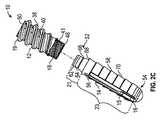
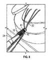
図1Aは、結び目のない(ノットレス)インプラントすなわち縫合糸アンカー10及びインプラント送達装置22を含む固定システム1の斜視図を示す。図1Bは、インプラント送達装置22に取り付けられたアンカー10の拡大図を示す。縫合糸アンカー10は、軟部組織の裂傷の修復を含む様々な外科的処置に使用可能である。単なる例として、アンカー10は、股関節若しくは肩の関節唇の裂傷、膝の半月板の裂傷、回旋腱板の裂傷、又は手や足等の小さな骨の軟組織裂傷の修復(例えば側副靭帯の修復、舟状骨の修復等)に使用可能である。換言すればアンカー10は、適切な再付着のために軟部組織を骨に固定すべきあらゆる状況で使用可能である。アンカー10はノットレスアンカーであるため、結び目を利用する軟組織修復に関連する多くの欠陥に悩まされない。加えて、アンカー10は、縫合糸アンカー10に対して縫合糸を固定するための改良された機構を含み得る。 FIG. 1A shows a perspective view of a fixation system 1 including a knotless implant or
縫合糸アンカー10は、アンカー本体12と、アンカー本体12の遠位端18に位置する遠位部材14とを含む。遠位部材14は、アイレット16と、1つ以上の縫合糸20を受容可能なスロット56とを含むアパーチャ15を有し得る。本明細書で論じるように、アンカー本体12及び遠位部材14は互いに独立して回転可能である。縫合糸20は、先ずアイレット16に通され、準備された骨穴内への縫合糸アンカー10の挿入の一部のためにアイレット16内で位置決めされる。挿入中、縫合糸20に張力をかけた後、縫合糸20はアイレット16からスロット56内に移動することができ、これにより、縫合糸アンカー10と縫合糸20との間の結合力が増加し、縫合糸が滑るリスクが低減する。例えば、スロット56内に係合している縫合糸20は、さらに「クリート(cleat)」固定されることができる。 The
インプラント送達装置22は、カニューレ状外側シャフト24を含む駆動シャフト部分6、内側シャフト26を含む縫合糸プーリーシャフト部分8、遠位ハンドル30を含むハンドル部分28、及び回転ノブ33を含む近位ハンドル32を有する。インプラント送達装置22を使用して、縫合糸アンカー10を準備された骨穴内に配置することができる。 The
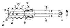
ここで図2A−図2C、図3A及び図3Bを参照すると、縫合糸アンカー10の斜視図及び断面図が示される。アンカー本体12は、近位表面50を含む近位端19から遠位表面46を含む遠位端18まで延び得る。アンカー本体12は、ねじ山38を備えた外表面と、マーキング(例えばエッチングマーク41)を含む外表面の一部とを有し得る。本明細書で説明するように、挿入中は、縫合糸に張力をかけて回転力によって縫合糸アンカー10を最終位置まで前進させる前に、エッチングマーク41の上部が骨表面上又は該骨表面より下方に位置するまで、縫合糸アンカー10を(非回転式に)挿入することができる。一例では、スロット56の長さ55は、エッチングマーク41の近位端からアンカー本体12の近位端19までの長さ57以上であり得る。このことは、縫合糸アンカー10が挿入されるにつれて縫合糸に過度の張力がかからないリスクを低減する。 Here, with reference to FIGS. 2A-2C, 3A and 3B, a perspective view and a cross-sectional view of the
ねじ山38が示されているが、任意の代替的な前進・固定機構が単独で又は組み合わせて使用することができ、例えば、節状若しくは畝状の表面、粗面、リブ、アンカー本体12の一部若しくは全周に亘って延びる周方向の溝等を含む。加えて、アンカー本体12は、挿入中に骨/組織を受容し、骨が縫合糸アンカー10の周りで治癒する際の骨結合を支援するための穿孔40も含み得る。
アンカー本体12は、近位端19から遠位端18までアンカー本体12を通って延びる穴36を画定することができる。穴36は、本明細書で論じるように、連結時に遠位部材14の表面と係合する停止面42(図3A〜図3B)を画定することができる。停止面42の近位の穴36の一部は、カニューレ状外側シャフト24からアンカー本体12に回転力を伝達できるように、カニューレ状外側シャフト24の回転防止構造に適合する回転防止構造44(図2B参照)を含むことができる。 The
アンカー10は、アンカー本体12に対して回転可能な遠位部材14を含む。遠位部材14は突起58とともに示されており、突起58は、穴の壁(骨穴)を貫通するのに十分な外向きの力を生じさせ、縫合糸アンカー10が穴から後退することを防止するように作用する。突起58が示されているが、バー又はスパイク等の任意の固定機構が使用可能である。加えて、遠位部材14は、突起、返し、スパイク等を備えず、固定機構のない実質的に滑らかな外表面を有することもできる。 The
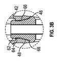
図2C、図3A及び図3Bに示すように、遠位部材14は、近位端52から遠位端54まで延びることができ、連結部分21及び縫合糸部分23を含み得る。連結部分21は、アンカー本体12内に受容されるように構成され、縫合糸部分23は、遠位部材14内で1つ以上の縫合糸を受容し、該縫合糸の移動を可能にするように構成される。遠位部材14は、1つ以上の縫合糸を受容する大きさのアパーチャ15を含む。 As shown in FIGS. 2C, 3A and 3B, the
アパーチャ15は、アイレット16及びスロット56を含む。アイレット16及びスロットはそれぞれ断面方向の最大寸法を有することができ、スロット56の最大寸法はアイレット16のそれよりも小さい。アイレット16は移行部分25を含むことができ、移行部分25はスロット56に隣接するテーパ面である。本明細書で論じるように、1つ以上の縫合糸が、先ずアイレット16に通され、挿入中に、アイレット16からスロット56に移動して、縫合糸を縫合糸アンカー10にさらに固定することができる。移行部分25は、アイレット16からスロット56への縫合糸の移動を可能にする。アイレット16及びスロット56は集合的に、遠位部材14を通って延びるアパーチャ15を画定する。アイレット16の移行部分25が有し得る断面方向の最大寸法は、スロット56に隣接する断面方向の最小寸法に移行する。移行部分25に沿ったこの寸法の差によって、アイレット16とスロット56との間にネック領域が形成され、該ネック領域によって縫合糸は、縫合糸の配置中に、スロット56に向かいかつスロット56内に移動することができる。縫合糸アンカー10が骨穴の中に前進するにつれて、縫合糸20はスロット56内に移動する。例えば、外側シャフト24及び縫合糸アンカー10が遠位方向に前進し、スロット56が縫合糸20上を移動するとき、内側シャフト26は静止した(すなわち並進的に固定された)状態に維持される。 The
連結部分21は、連結部分21と縫合糸部分23との間に肩68が画定されるように縫合糸部分23から延びることができる。連結部分21は、突起66及びリップ62を含む。図3A及び図3Bに示すように、遠位部材14がアンカー本体12に結合されると、突起66は穴36内に延び、リップ62はアンカー本体12の穴36の停止面42に近接配置される。リップ62の直径は、停止面42に沿う直径より大きくすることができる。連結部分21は、リップ62が僅かに圧縮されて停止面42を越えて前進するまで、穴36内に前進することができる。リップ62が停止面42を越えて前進すると、リップ62は拡張し、リップ62の停止面64が穴36の停止面42に係合して、遠位部材14とアンカー本体12とが連結される。図示するように、アンカー本体12の停止面42の遠位にある穴36の部分の断面形状は、円形であり、先細の直径を有することができる。一般に、穴36の部分の形状及び直径は、連結部分21の突起66の形状及び直径と一致し、その結果、連結部分21は、アンカー本体12に連結されている間、アンカー本体12に対して自由に回転可能である。リップ62の停止面64と肩68との間の距離は、穴36の停止面42とアンカー本体12の遠位面46との間の距離に実質的に等しいかそれより大きくすることができる。 The connecting
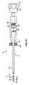
インプラント送達装置22は、図4A−図4Cに示される。インプラント送達装置22は、カニューレ状外側シャフト24を含む駆動シャフト部分6、内側シャフト26を含む縫合糸プーリーシャフト部分8、遠位ハンドル30、及び近位ハンドル32を含む。カニューレ状外側シャフト24は、近位端92から遠位端94まで延びる。近位端92は、近位ハンドル32の本体88に連結され、近位ハンドル32のノブ33が回転すると、カニューレ状外側シャフト24も同様に回転する。カニューレ状外側シャフト24、本体88及びノブ33は、互いに一体であってもモジュール式であってもよい。カニューレ状外側シャフト24の遠位端94は、アンカー本体12の穴36の回転防止構造44(図2Bを参照)に適合する回転防止構造(例えば六角形)を有する係合端97を含む。係合端部97が縮径された部分を有することにより停止面95が形成され、停止面95は、縫合糸アンカー10がインプラント送達装置22上に取り付けられたとき(図6を参照)に、アンカー本体12の近位面50と係合するように構成される。本体部分88は、窓90及びねじ山89を含む。本明細書で論じるように、ねじ山89が遠位ハンドル30と係合することにより、近位ハンドルのノブ33が回転すると、近位ハンドル32の位置が遠位ハンドル30に対して移動する。 The
遠位ハンドル30は、近位端80から遠位端82まで延び、穴70を画定する。また遠位ハンドル30は、窓84を有する。内側シャフト26は、近位端72から遠位端74まで延び、遠位端74はフォーク75を有する。また内側シャフト26は、クリップ78を受容可能な溝76を有する。さらに、遠位ハンドル30は、張力をかけた後の縫合糸の扱いを補助するために、挿入時に使用できる止め具(クリート)81を含む縫合糸把持部83を有し得る。 The
図4Bに示すように、内側シャフト26は遠位ハンドル30の遠位端82において穴70内に挿入され、カニューレ状外側シャフト24は内側シャフト26上を延びるように遠位ハンドル30の近位端80において穴70内に挿入される。組み立てられると、遠位ハンドル30の窓84と本体88の窓90とが位置合わせされ、溝76が窓84内に配置され、それによりクリップは、窓84を介して遠位ハンドル30を通り、窓90を介して本体88を通って挿入され、内側シャフト26の溝76に係合することができる。クリップ78は、内側シャフト26を遠位ハンドル30に連結する一方、近位ハンドル32、本体88及びカニューレ状外側シャフト24を、内側シャフト26について回転可能にする。例えば、クリップ78が内側シャフト26に係合すると、クリップ78は、窓90を通って、穴70を横切って延びる窓84内に延び、それにより内側シャフト26及び遠位ハンドル30の並進位置が固定される。窓90は、近位ハンドル32が長手軸に沿って移動できる長さ以上の長さを有し、これは、本体88のねじ山89と近位ハンドル32のスロット86との係合によって決定される。一旦組み立てられると、ノブ33の回転によって近位ハンドル32が回されると、クリップ78は窓90の縁に係合して、遠位ハンドル30内で内側シャフト26について回転し、それにより内側シャフト26は、遠位ハンドル30に対する回転・並進位置を維持することができる。すなわち、クリップ78が内側シャフト26について回転するとき、内側シャフト26はクリップ78から独立しており、遠位ハンドル30に対して一定の回転・並進位置を維持する。縫合糸の張力はさらに、近位ハンドル32が回されるときに内側シャフト26の回転位置を維持することを補助する。As shown in FIG. 4B, the
図5はインプラント送達装置22のさらなる詳細を示し、図6はインプラント送達装置22に取り付けられた縫合糸アンカー10を示す。図5に示すように、カニューレ状外側シャフト24はその遠位端94に係合部分96を有する。内側シャフト26は、カニューレ状外側シャフト24を貫通し、内側シャフト26の遠位端74にフォーク状端部75を備える。また内側シャフト26は、縫合糸アンカー10の一部と圧入部を形成するように構成された拡張部分98を有する。一例では、拡張部分98は、遠位部材14の内側の2つの平坦部に嵌合する2つの平坦部を含む。しかしながら、拡張部分98と縫合糸アンカー10との間には、他の回転防止構造を使用することもできる。 FIG. 5 shows further details of the
図5及び図6を参照すると、縫合糸アンカー10がインプラント送達装置22に取り付けられると、係合部分96は、アンカー本体12の穴36の回転防止構造44と係合する(図2Bも参照)。近位ハンドル32のノブ33(図1参照)に回転力が加えられると、該回転力が係合部分96を介してアンカー本体12に伝達され、アンカー本体12は外表面のねじ山38によって穴内で回転駆動される。遠位部材14はアンカー本体12に対して回転可能であるため、アンカー本体12がねじ込み式に埋植されるときに遠位部材14は回転しない。カニューレ状外側シャフト24は肩95を有し、肩95は、アンカー本体12がインプラント送達装置22に完全に着座したときにアンカー本体12の近位表面50に当接することができる。 Referring to FIGS. 5 and 6, when the
内側シャフト26の拡張部分98は、縫合糸アンカー10の一部と係合するように構成される。一例では、拡張部分98は、遠位部材14の連結部分21内で、遠位部材14と圧入部を形成する。内側シャフト26の遠位端74は、カニューレ状外側シャフト24の遠位端94を越えて遠位方向に延在可能であり、これにより、カニューレ状外側シャフト24の遠位端94がアンカー本体12の近位表面50と係合するとき、内側シャフト26の遠位端74は、アンカー本体12を通ってアンカー本体12の遠位端46を越えた距離まで延在して、アイレット16内に配置された縫合糸と係合することができる。フォーク状端部75を有する遠位端74は、アンカー本体12が回転式に挿入されるまで、縫合糸が遠位部材14内で遠位に保持されることを可能にする。フォーク状端部75は、縫合糸の位置を維持し、縫合糸がスロット56に早期に入ってしまうことを防止する。縫合糸アンカー10の前進中、外側シャフト24は、縫合糸アンカー10が骨穴内に前進するのと同じ速度で内側シャフト26上を前進し、それにより縫合糸20は、過度に緊張することなくスロット56内に入ることができる。これは、クリップ78が内側シャフト26の並進をロックする一方で、近位ハンドル32のねじ山89が遠位ハンドル30のスロット86と嵌合するためである。 The
従ってアンカーシステムは、アンカー本体12が穴内に完全に埋め込まれる前に、アンカー本体12から遠位の穴内の位置で縫合糸に張力がかかるように構成される。これにより、より良好かつ容易なインプラントが可能になり、アンカーが埋め込まれる前に外科医が縫合糸に所望の張力をかけることができる。 Thus, the anchor system is configured to tension the suture at a position within the hole distal to the
縫合糸アンカー10を埋植し、縫合糸アンカー10を使用して軟組織を修復する方法がここで開示される。後述する方法は単なる例示であり、特定のステップは特定の順序で説明できるが、その順序は必須ではなく、説明したものとは異なる順序でステップを実行してもよい。単なる例として使用される以下の特定の方法は、回旋腱板を修復するものである。しかしながら、縫合糸アンカー10は、軟組織を体内の自然な状態に引き戻すあらゆる修復に使用できると考えられる。 Disclosed herein is a method of implanting a
一例ではこの方法は、先ず、患者の肩の皮膚及び組織を通るアクセスポータルを(例えば経皮カニューレを使用して)形成することを含む。この場合も、膝、臀部、足首、又は他の小さな骨の修復等、他の解剖学的位置が考えられる。アクセスポータルが形成されたら、1つ以上の縫合糸をアクセスポータルから手術部位に通し、軟部組織(この場合は患者の肩の回旋腱板)に通すことができる。1つ以上の縫合糸は、1つ以上の位置で軟部組織を通して挿入可能である。一例として、縫合糸は、様々な場所の軟部組織を通して配置可能である。経骨の等価物に使用される縫合糸構造等、複数の縫合糸が使用される場所を含む、他の多くの縫合糸構造が使用可能である。 In one example, this method first involves forming an access portal (eg, using a percutaneous cannula) through the skin and tissue of the patient's shoulder. Again, other anatomical locations such as knee, buttocks, ankle, or other small bone repairs are possible. Once the access portal is formed, one or more sutures can be passed from the access portal through the surgical site and through the soft tissue (in this case the rotator cuff of the patient's shoulder). One or more sutures can be inserted through the soft tissue at one or more positions. As an example, sutures can be placed through soft tissue at various locations. Many other suture structures are available, including where multiple sutures are used, such as the suture structure used for the warp bone equivalent.
図7−図12は、固定システムの使用方法を示す。縫合糸の自由端は、アクセスポータルから引き出され、縫合糸通し器として使用される材料のループ等の適切な器具を使用して、縫合糸アンカー10のアイレット16に通すことができる。アイレット16を通る縫合糸20の自由端により、外科医は自由端をつかみ、インプラント送達装置22を使用してアクセスポータルを通して縫合糸アンカー10を挿入することができる。 7-12 show how to use the fixation system. The free end of the suture is drawn from the access portal and can be threaded through the
図7に示すように、縫合糸アンカー10はインプラント送達装置22に取り付けられ、縫合糸20の自由端はアイレット16を通って延びる。縫合糸アンカー10は、インプラント送達装置22に事前に取り付けることができ、或いは外科医は、縫合糸20の自由端がアイレット16を通して引かれる前又は後に、縫合糸アンカー10をインプラント送達装置22に取り付けることができる。次に外科医は、縫合糸20の自由端を把持し、インプラント送達装置22を使用して、アクセスポータルを通して患者の肩に縫合糸アンカー10を挿入することができる。 As shown in FIG. 7, the
予め、すなわち縫合糸アンカー10が骨内に打ち込まれる前の任意の時点で、外科医は適切な千枚通し、パイロットドリル又は他の器具を使用して、縫合糸アンカー10を受容する開口部を患者の骨に形成することができる。準備された穴は、縫合糸アンカー10の先端に位置している。図8及び図9は、準備された穴内に挿入されている縫合糸アンカー10を示している。図2A−図2Cに関して論じたように、アンカー本体12は、張力が縫合糸20に作用可能であるときの表示であるエッチングマーク41を含む。例えば、図9は、エッチングマーク41が骨表面の上又は下方にあり、複数の縫合糸20に個々に張力が作用可能であることを示している。例えば外科医は、縫合糸20の自由端に張力をかけて弛みを解消することができる。図10は、張力がかかった後の縫合糸20を示す。上述のように、縫合糸把持部83の止め具81は、張力をかけた後に縫合糸を操作するために使用可能である。この時点で、内側シャフト26は同じ位置にある。同時に、ノブ33を回転させてアンカー本体12を挿入すると、縫合糸20がスロット56に入り、縫合糸アンカー10と内側シャフト26との間の圧入が解除される。 In advance, at any time before the
エッチングマーク41が骨表面の上又は下方にあるときに縫合糸アンカー10が骨内に挿入されると、縫合糸20の自由端に張力がかかるように、縫合糸アンカー10は構成可能であることに留意されたい。従って、骨穴の壁と縫合糸アンカー10との間には、自由端に張力をかけることと、縫合糸アンカー10に対する縫合糸の移動(例えば、縫合糸がアイレット16からスロット56に移動する前)とを可能にする空間が存在し得る。 The
更なる張力が外科医によって自由端に加えられた後は、縫合糸20の組織係合側が軟部組織と係合できるため、縫合糸アンカー10を貫通する縫合糸20は、ノブ33が回転されてアンカー本体12が回転によって挿入されるときに、アイレット16からスロット56内に移動することができる。例えば、ノブ33が回転すると、カニューレ状外側シャフト24は内側シャフト26に対して遠位方向に移動し、縫合糸アンカー10を遠位方向に「押し」すなわち移動させ、それにより拡張部分98が縫合糸アンカー10の遠位部材14から外れ、スロット56が、スロット56に係合している縫合糸20上を遠位方向に移動する。 After additional tension is applied to the free end by the surgeon, the tissue engaging side of the
縫合糸20に張力をかけたら、縫合糸アンカー10をさらに穴内に前進させることができる。例えば、図1A、図4A及び図11を参照すると、外科医は、遠位ハンドル30に対して僅かに下向きの圧力を加える一方で、近位ハンドル32のノブ33を時計回りに回して、縫合糸アンカー10のねじ山付きアンカー本体12を前進させることができる。ノブ33が回転すると、回転力が縫合糸アンカー10のアンカー本体12に伝達され、それにより近位ハンドル32、カニューレ状外側シャフト24及びアンカー本体12が長手方向軸を中心に回転する一方で、内側シャフト26、遠位部材14及び遠位ハンドル30は、一定の回転位置に維持される(すなわち、それらは縫合糸20の張力によって回転しない)。外科医は、縫合糸アンカー10が完全に着座するまでノブ33を回転させ続ける。After tension is applied to the
完全に着座すると、外科医は、例えばハンドル部分28を後方に引っ張ることによってインプラント送達装置22を取り外し、縫合糸アンカーからインプラント送達装置22を引き抜くことができる。加えて、外科医は、骨穴の外側に延びる縫合糸20の自由端による余分な縫合糸材料を切り取ることができる。その後、修復を完了できる。 When fully seated, the surgeon can remove the
図示された装置では、特定の構造が、縫合糸アンカーとして、又はその埋植方法での使用に適しているものとして示されている。本開示は、そのような目的のための代替構造の使用も想定している。例えば、遠位部材14は閉鎖端を有するように示されているが、遠位部材14は開放端を有してもよい。アンカー本体及び遠位部材は、返し、突起、ねじ山、溝、隆起等の様々な前進・固定手段を含み得る。遠位部材とアンカー本体との間の連結は、アンカー本体に挿入される遠位部材として示されている。しかし、例えば、アンカー本体の一部が遠位部材に挿入される等、他の連結機構も使用可能である。さらに、縫合糸アンカーがエッチングライン(本明細書にて説明)まで前進した後に張力をかける代わりに、縫合糸アンカー10を骨穴に挿入する前に縫合糸に張力をかけてもよく、それにより外科医は縫合糸に追加の張力を加える必要がなくなる。さらに、骨穴の壁と縫合糸アンカー10との間の空間は、組織に過度の張力がかからないように、非組織側の縫合糸が動くことを可能にする。 In the illustrated device, a particular structure is shown as suitable for use as a suture anchor or in a method of implantation thereof. The present disclosure also envisages the use of alternative structures for such purposes. For example, the
本発明の主題の本質を説明するために記載及び図示された部品及び方法の詳細、材料及び配置における様々な他の変更が、従属請求項に記載されている本発明の主題の原理及び範囲から逸脱することなく行えることは、当業者に容易に理解されよう。 Various other changes in the details, materials and arrangements of parts and methods described and illustrated to illustrate the essence of the subject matter of the invention are from the principles and scope of the subject matter of the invention described in the dependent claims. Those skilled in the art will easily understand what can be done without deviation.
また、様々な従属請求項、実施例、及びそれらに記載されている特徴は、上述の及び/又は最初の請求項に提示されたものとは異なる方法で組み合わせることができることも理解されよう。例えば、上記の実施例のいかなる構造も、上述した実施例の他の構造と共有でき、或いは又はこれに加え、特定の従属請求項の構造は、当業者に理解可能な組み合わせによって、他の従属項又は独立項と共有できる。 It will also be appreciated that the various dependent claims, examples, and features described therein can be combined in a manner different from that presented in the above and / or first claim. For example, any structure of the above embodiment may be shared with other structures of the above embodiment, or in addition, the structure of a particular dependent claim may be dependent on another in a combination understandable to those skilled in the art. Can be shared with terms or independent terms.
諸注意
上記の詳細な説明は、発明を実施するための形態の一部を形成する添付図面の参照を含む。図面は、例示として、本発明を実施するための具体的な実施形態を示す。これらの実施形態は、本明細書では「(実施)例(examples)」とも称する。これらの実施例は、図示又は説明する要素以外の要素を含むことができる。但し、本発明者は、図示又は説明する要素のみが提供される実施例も想定する。さらに、本発明者は、特定の実施例(又はその1つ以上の形態)に関連して、あるいは本明細書において図示又は説明する他の実施例(又はその1つ以上の形態)に関連して、図示又は説明する要素の任意の組み合わせ又は並び替えを用いる実施例も想定する。NOTE The above detailed description includes reference to the accompanying drawings forming part of the embodiment for carrying out the invention. The drawings, by way of example, show specific embodiments for carrying out the present invention. These embodiments are also referred to herein as "(examples)". These examples may include elements other than those illustrated or described. However, the inventor also envisions an embodiment in which only the elements illustrated or described are provided. In addition, the inventor relates to a particular embodiment (or one or more embodiments thereof), or to other embodiments illustrated or described herein (or one or more embodiments thereof). Further, an embodiment using an arbitrary combination or rearrangement of the elements shown or described is also assumed.
本明細書と、参照により本明細書に組み込まれた文献との間で使用法に一貫性がない場合、本明細書の使用法が優先する。 In the event of inconsistency in usage between the specification and the literature incorporated herein by reference, the usage herein shall prevail.
本明細書では、「a」又は「an」なる語は、特許文献において一般的であるように、「少なくとも1つ」又は「1つ以上」の使用又は他の例に関係なく、1つ又は複数を含むものとして用いられる。本明細書では、「又は(or)」は特に指示がない限り非排他的に用いられ、例えば「A又はB」は、「BではなくA」、「AではなくB」並びに「A及びB」を含む。本明細書では、「including」及び「in which」なる語は、それぞれ「comprising」及び「wherein」の平易な英語の同等語として使用される。また、特許請求の範囲において、「including」及び「comprising」に制限はなく、すなわちシステム、装置、物品、組成物、処方又は工程なる用語は、ある請求項においてこれらの用語の後に列記される要素以外の要素も含み、そのようなシステム等も特許請求の範囲内であるとする。さらに、特許請求の範囲における「第1」、「第2」及び「第3」等の用語は、単なる標識として使用され、それらの対象に数値的要件を課すものではない。 As used herein, the word "a" or "an" is one or more, as is common in the patent literature, regardless of the use of "at least one" or "one or more" or other examples. Used as including multiple. In the present specification, "or (or)" is used non-exclusively unless otherwise specified, for example, "A or B" is "A not B", "B not A" and "A and B". "including. As used herein, the terms "including" and "in which" are used as plain English equivalents of "comprising" and "where in," respectively. Also, within the scope of the claims, there is no limitation on "including" and "comprising", that is, the terms system, device, article, composition, formulation or process are the elements listed after these terms in a claim. It is assumed that such a system, etc. is also within the scope of the claims, including elements other than the above. Furthermore, terms such as "first", "second" and "third" in the claims are used merely as markers and do not impose numerical requirements on their objects.
上記の説明は例示を意図しており、限定的なものではない。例えば、上述の実施例(又はその1つ以上の形態)は、互いに組み合わせて使用できる。上述の説明を検討すれば、当業者等は他の実施形態を使用できる。要約は、37 C.F.R.§1.72(b)に準拠し、読者が迅速に技術的開示の本質を理解できるように提供される。要約は、請求項の範囲又は意味を解釈又は限定するためには使用されないという理解のもとで提出される。また、上述の「発明を実施するための形態」において、開示を簡素化するために、種々の特徴をグループ化することができる。このことは、特許請求の範囲に含まれずかつ開示された特徴が、請求項にとって必須であることを意図するものとして解釈されるべきではない。むしろ、本発明の主題は、特定の開示された実施例の全て特徴より少ない特徴の中に存在する。従って、特許請求の範囲は、実施例又は実施形態として「発明を実施するための形態」に組み込まれ、各請求項は、別個の実施形態として独立しており、このような実施例は、種々の組み合わせ又は並べ替えで互いに組み合わせ可能であることが想定されている。本発明の範囲は、添付の請求項と、当該請求項と同等物の全範囲とを参照して定められるべきである。 The above description is intended as an example and is not limiting. For example, the above embodiments (or one or more embodiments thereof) can be used in combination with each other. Considering the above description, those skilled in the art can use other embodiments. The abstract is in accordance with 37 C.F.R. §1.72 (b) and is provided so that the reader can quickly understand the nature of the technical disclosure. The abstract is submitted with the understanding that it will not be used to interpret or limit the scope or meaning of the claims. Further, in the above-mentioned "mode for carrying out the invention", various features can be grouped in order to simplify the disclosure. This should not be construed as intending that the features not included in the claims and disclosed are essential to the claims. Rather, the subject matter of the present invention resides in less than all features of a particular disclosed embodiment. Therefore, the scope of claims is incorporated into "the embodiment for carrying out the invention" as an embodiment or an embodiment, and each claim is independent as a separate embodiment, and such an embodiment is various. It is assumed that they can be combined with each other by combining or rearranging. The scope of the invention should be defined with reference to the appended claims and the full scope of the equivalent of the claims.
Claims (18)
Translated fromJapanese前記縫合糸アンカーは、
ねじ山を備えた外表面を有するアンカー本体と、
前記アンカー本体に対して長手方向の縫合糸アンカー軸回りに回転可能な遠位部材と、を有し、
前記遠位部材は、該遠位部材を横切るアパーチャを有し、該アパーチャはアイレット及びスロットを含み、前記アイレット及び前記スロットは、前記アイレットの断面方向の最大寸法が前記スロットの断面方向の最大寸法よりも大きく、かつ、張力がかけられた縫合糸が挿入中に前記アイレットから前記スロット内に移動して固定されるような寸法を有する、固定システム。A fixation system with suture anchors,
The suture anchor is
Anchor body with an outer surface with threads,
It has a distal member that is rotatable about the suture anchor axis in the longitudinal direction with respect to the anchor body.
The distal member has an aperture that traverses the distal member, the aperture includes an eyelet and a slot, and the eyelet and the slot havea maximum cross-sectional dimension of the eyelet and a maximum cross-sectional dimension of the slot. A fixation system that is larger and has dimensions such thatthe tensioned suture moves from the eyelet into the slot during insertion and is secured.
ハンドル部分と、
前記アンカー本体の近位端に係合して前記縫合糸アンカーを穴内に打ち込むように構成されたカニューレ状外側シャフトを有する駆動シャフト部分と、
前記カニューレ状外側シャフト内に摺動可能に受容される内側シャフトを有する縫合糸プーリーシャフト部分と、を有し、
前記内側シャフトの遠位端は、前記カニューレ状外側シャフトの遠位端を越えて遠位方向に延在可能であり、それにより、前記カニューレ状外側シャフトが前記アンカー本体の近位端に係合するときに、前記内側シャフトの遠位端は、前記遠位部材と係合して該遠位部材を前記内側シャフトに対して回転できないように固定するために、前記アンカー本体を通って前記アンカー本体の遠位端を越える距離まで延在可能である、請求項1〜9のいずれか1項に記載の固定システム。Further having an implant delivery device, the implant delivery device is
The handle part and
A drive shaft portion having a cannula-like outer shaft configured to engage the proximal end of the anchor body to drive the suture anchor into the hole.
With a suture pulley shaft portion having an inner shaft that is slidably received within the cannula-like outer shaft.
The distal end of the inner shaft can extend distally beyond the distal end of the cannulated outer shaft, whereby the cannulated outer shaft engages the proximal end of the anchor body. When the distal end of the inner shaft engages with the distal member and secures the distal member so that it cannot rotate with respect to the inner shaft, the anchor body passes through the anchor body. The fixation system according to any one ofclaims 1 to 9 , which can extend beyond the distal end of the body.
前記縫合糸アンカーは、
アンカー本体と、前記アンカー本体に対して長手方向の縫合糸アンカー軸回りに回転可能な遠位部材と、を有し、
前記遠位部材は、該遠位部材を横切るアパーチャを有し、該アパーチャはアイレット及びスロットを含み、前記アイレット及び前記スロットは、前記アイレットの断面方向の最大寸法が前記スロットの断面方向の最大寸法よりも大きく、かつ、張力がかけられた縫合糸が挿入中に前記アイレットから前記スロット内に移動して固定されるような寸法を有し、
前記インプラント送達装置は、
ハンドル部分と、
前記アンカー本体の近位端に係合して前記縫合糸アンカーを穴内に打ち込むように構成されたカニューレ状外側シャフトを有する駆動シャフト部分と、
前記カニューレ状外側シャフト内に摺動可能に受容される内側シャフトを有する縫合糸プーリーシャフト部分と、を有し、
前記内側シャフトの遠位端は、前記カニューレ状外側シャフトの遠位端を越えて遠位方向に延在可能であり、それにより、前記カニューレ状外側シャフトが前記アンカー本体の近位端に係合するときに、前記内側シャフトの遠位端は、前記遠位部材と係合して該遠位部材を前記内側シャフトに対して回転できないように固定するために、前記アンカー本体を通って前記アンカー本体の遠位端を越える距離まで延在可能である、固定システム。A fixation system with suture anchors and implant delivery devices,
The suture anchor is
It has an anchor body and a distal member that is rotatable about the suture anchor axis in the longitudinal direction with respect to the anchor body.
The distal member has an aperture that traverses the distal member, the aperture includes an eyelet and a slot, and theeyelet and the slot have a maximum cross-sectional dimension of the eyelet and a maximum cross-sectional dimension of the slot. Larger and sized so that the tensioned suture moves from the eyelet into the slot during insertion and is secured.
The implant delivery device is
The handle part and
A drive shaft portion having a cannula-like outer shaft configured to engage the proximal end of the anchor body to drive the suture anchor into the hole.
With a suture pulley shaft portion having an inner shaft that is slidably received within the cannula-like outer shaft.
The distal end of the inner shaft can extend distally beyond the distal end of the cannulated outer shaft, whereby the cannulated outer shaft engages the proximal end of the anchor body. When the distal end of the inner shaft engages with the distal member and secures the distal member so that it cannot rotate with respect to the inner shaft, the anchor body passes through the anchor body. A fixation system that can extend beyond the distal end of the body.
Applications Claiming Priority (5)
| Application Number | Priority Date | Filing Date | Title |
|---|---|---|---|
| US201762532705P | 2017-07-14 | 2017-07-14 | |
| US62/532,705 | 2017-07-14 | ||
| US201762592896P | 2017-11-30 | 2017-11-30 | |
| US62/592,896 | 2017-11-30 | ||
| PCT/US2018/042032WO2019014557A1 (en) | 2017-07-14 | 2018-07-13 | Anchoring system and method for securing a suture to a pre-drilled bore |
Publications (2)
| Publication Number | Publication Date |
|---|---|
| JP2020527435A JP2020527435A (en) | 2020-09-10 |
| JP6978599B2true JP6978599B2 (en) | 2021-12-08 |
Family
ID=63077993
Family Applications (1)
| Application Number | Title | Priority Date | Filing Date |
|---|---|---|---|
| JP2020523232AActiveJP6978599B2 (en) | 2017-07-14 | 2018-07-13 | Fixation system and method for fixing sutures in preformed drill holes |
Country Status (7)
| Country | Link |
|---|---|
| US (1) | US12239308B2 (en) |
| EP (1) | EP3651657B1 (en) |
| JP (1) | JP6978599B2 (en) |
| CN (1) | CN111050669B (en) |
| AU (1) | AU2018300174B2 (en) |
| CA (1) | CA3069688C (en) |
| WO (1) | WO2019014557A1 (en) |
Families Citing this family (13)
| Publication number | Priority date | Publication date | Assignee | Title |
|---|---|---|---|---|
| JP6978599B2 (en) | 2017-07-14 | 2021-12-08 | バイオメット スポーツ メディスン,リミティド ライアビリティ カンパニー | Fixation system and method for fixing sutures in preformed drill holes |
| CN110403690B (en)* | 2019-08-27 | 2025-01-21 | 北京天星医疗股份有限公司 | Repair fixation screws and ligament repair fixation components |
| WO2021222172A2 (en) | 2020-04-29 | 2021-11-04 | DePuy Synthes Products, Inc. | Knotless anchor insertion |
| CN111467084B (en)* | 2020-05-29 | 2024-09-20 | 科瑞迈吉(苏州)医疗科技有限公司 | Input handle of wire locking device |
| EP4280973A4 (en)* | 2021-01-22 | 2025-02-12 | Paragon 28, Inc. | SOFT TISSUE IMPLANTS, INSTRUMENTATION AND METHODS |
| FR3120306B1 (en)* | 2021-03-02 | 2025-06-20 | Rs4 | Suture anchor for anchoring soft tissue to bone |
| USD1028232S1 (en) | 2021-04-27 | 2024-05-21 | Medos International Sarl | Suture anchor insertion device |
| US12137894B2 (en) | 2021-12-30 | 2024-11-12 | Medos International Sarl | Knotless anchor inserter tool extraction |
| USD1019945S1 (en) | 2021-12-30 | 2024-03-26 | Medos International Sarl | Suture anchor insertion device |
| CN114366203B (en)* | 2022-01-12 | 2022-07-15 | 北京天星博迈迪医疗器械有限公司 | A new type of full suture anchor implanter |
| US20240108323A1 (en)* | 2022-09-30 | 2024-04-04 | DePuy Synthes Products, Inc. | Screw-in knotless suture anchor |
| CN117462189A (en)* | 2023-11-03 | 2024-01-30 | 北京市春立正达医疗器械股份有限公司 | A new material for knot-free anchors with wires |
| CN119014931A (en)* | 2024-10-31 | 2024-11-26 | 上海声拓医疗科技有限公司 | Suture anchor implantation device and system |
Family Cites Families (20)
| Publication number | Priority date | Publication date | Assignee | Title |
|---|---|---|---|---|
| US6306159B1 (en)* | 1998-12-23 | 2001-10-23 | Depuy Orthopaedics, Inc. | Meniscal repair device |
| US7993369B2 (en)* | 2000-06-22 | 2011-08-09 | Arthrex, Inc. | Graft fixation using a plug against suture |
| US7517357B2 (en) | 2003-01-09 | 2009-04-14 | Linvatec Biomaterials | Knotless suture anchor |
| US7572283B1 (en)* | 2004-12-07 | 2009-08-11 | Biomet Sports Medicine, Llc | Soft tissue rivet and method of use |
| US20090192546A1 (en)* | 2005-03-30 | 2009-07-30 | Reinhold Schmieding | Fenestrated suture anchor and method for knotless fixation of tissue |
| US20080009904A1 (en)* | 2006-03-17 | 2008-01-10 | Bourque Barnard J | Soft Tissue Fixation |
| AU2009246785B2 (en)* | 2008-05-14 | 2015-05-28 | Smith & Nephew, Inc. | Arthroscopic biceps tenodesis repair |
| WO2010005749A1 (en) | 2008-06-16 | 2010-01-14 | Cayenne Medical, Inc. | Anchors and methods for securing suture to bone |
| US8790368B2 (en)* | 2008-09-18 | 2014-07-29 | Smith & Nephew, Inc. | Tenodesis implant |
| AU2010319662B2 (en)* | 2009-11-10 | 2015-11-19 | Smith & Nephew, Inc. | Locking suture anchor assembly |
| EP2763597B1 (en)* | 2011-10-03 | 2018-01-24 | Cayenne Medical, Inc. | Suture anchors |
| US9364210B2 (en)* | 2012-01-27 | 2016-06-14 | Arthrocare Corporation | Biased wedge suture anchor and method for soft tissue repair |
| WO2013114347A1 (en)* | 2012-02-05 | 2013-08-08 | Implament Pty Limited | Suture anchor with cleat formation to secure suture thread |
| EP2967535A4 (en)* | 2013-03-15 | 2016-11-16 | Mark Brunsvold | Suture anchor |
| US9451954B2 (en)* | 2013-03-15 | 2016-09-27 | Howmedica Osteonics Corp. | Ratcheting inserter device and suture anchor arrangement |
| US9936940B2 (en)* | 2013-06-07 | 2018-04-10 | Biomet Sports Medicine, Llc | Method and apparatus for coupling soft tissue to bone |
| US9655609B2 (en)* | 2013-07-10 | 2017-05-23 | Tepha, Inc. | Soft suture anchor |
| US10722343B2 (en)* | 2017-02-22 | 2020-07-28 | Stryker Corporation | Fixation member with separate eyelet and methods of use thereof |
| US11116493B2 (en)* | 2017-05-25 | 2021-09-14 | Biomet Manufacturing, Llc | Knotless lateral row implant |
| JP6978599B2 (en) | 2017-07-14 | 2021-12-08 | バイオメット スポーツ メディスン,リミティド ライアビリティ カンパニー | Fixation system and method for fixing sutures in preformed drill holes |
- 2018
- 2018-07-13JPJP2020523232Apatent/JP6978599B2/enactiveActive
- 2018-07-13EPEP18749254.1Apatent/EP3651657B1/enactiveActive
- 2018-07-13CNCN201880057553.7Apatent/CN111050669B/enactiveActive
- 2018-07-13CACA3069688Apatent/CA3069688C/enactiveActive
- 2018-07-13USUS16/630,234patent/US12239308B2/enactiveActive
- 2018-07-13WOPCT/US2018/042032patent/WO2019014557A1/ennot_activeCeased
- 2018-07-13AUAU2018300174Apatent/AU2018300174B2/enactiveActive
Also Published As
| Publication number | Publication date |
|---|---|
| CA3069688C (en) | 2022-06-21 |
| JP2020527435A (en) | 2020-09-10 |
| WO2019014557A1 (en) | 2019-01-17 |
| CN111050669A (en) | 2020-04-21 |
| EP3651657A1 (en) | 2020-05-20 |
| AU2018300174A1 (en) | 2020-02-20 |
| US20200155140A1 (en) | 2020-05-21 |
| US12239308B2 (en) | 2025-03-04 |
| CN111050669B (en) | 2023-06-23 |
| CA3069688A1 (en) | 2019-01-17 |
| AU2018300174B2 (en) | 2021-06-24 |
| EP3651657B1 (en) | 2024-03-20 |
Similar Documents
| Publication | Publication Date | Title |
|---|---|---|
| JP6978599B2 (en) | Fixation system and method for fixing sutures in preformed drill holes | |
| US20210121170A1 (en) | Knotless suture anchor | |
| US20240050220A1 (en) | Fixation Member With Separate Eyelet And Methods Of Use Thereof | |
| JP6612909B2 (en) | Multiple suture nodule anchors and related methods for attaching tissue to bone | |
| US11083448B2 (en) | System and method for attaching soft tissue to bone | |
| EP3305210B1 (en) | System for securing tissue to bone | |
| US20210378656A1 (en) | Knotless lateral row implant | |
| US12053171B2 (en) | Knotless implants, instruments, and methods | |
| AU2012319123B8 (en) | Suture anchors and methods of use |
Legal Events
| Date | Code | Title | Description |
|---|---|---|---|
| A521 | Request for written amendment filed | Free format text:JAPANESE INTERMEDIATE CODE: A523 Effective date:20200323 | |
| A621 | Written request for application examination | Free format text:JAPANESE INTERMEDIATE CODE: A621 Effective date:20200323 | |
| A977 | Report on retrieval | Free format text:JAPANESE INTERMEDIATE CODE: A971007 Effective date:20210326 | |
| A131 | Notification of reasons for refusal | Free format text:JAPANESE INTERMEDIATE CODE: A131 Effective date:20210406 | |
| A521 | Request for written amendment filed | Free format text:JAPANESE INTERMEDIATE CODE: A523 Effective date:20210621 | |
| TRDD | Decision of grant or rejection written | ||
| A01 | Written decision to grant a patent or to grant a registration (utility model) | Free format text:JAPANESE INTERMEDIATE CODE: A01 Effective date:20211012 | |
| A61 | First payment of annual fees (during grant procedure) | Free format text:JAPANESE INTERMEDIATE CODE: A61 Effective date:20211111 | |
| R150 | Certificate of patent or registration of utility model | Ref document number:6978599 Country of ref document:JP Free format text:JAPANESE INTERMEDIATE CODE: R150 | |
| R250 | Receipt of annual fees | Free format text:JAPANESE INTERMEDIATE CODE: R250 |