JP6978442B2 - Integral point source for textured projection bulbs - Google Patents
Integral point source for textured projection bulbsDownload PDFInfo
- Publication number
- JP6978442B2 JP6978442B2JP2018564290AJP2018564290AJP6978442B2JP 6978442 B2JP6978442 B2JP 6978442B2JP 2018564290 AJP2018564290 AJP 2018564290AJP 2018564290 AJP2018564290 AJP 2018564290AJP 6978442 B2JP6978442 B2JP 6978442B2
- Authority
- JP
- Japan
- Prior art keywords
- light
- integrator
- light bulb
- bulb according
- light source
- Prior art date
- Legal status (The legal status is an assumption and is not a legal conclusion. Google has not performed a legal analysis and makes no representation as to the accuracy of the status listed.)
- Active
Links
- 239000000463materialSubstances0.000claimsdescription24
- 230000004438eyesightEffects0.000claimsdescription15
- 239000011248coating agentSubstances0.000claimsdescription8
- 238000000576coating methodMethods0.000claimsdescription8
- 238000009792diffusion processMethods0.000claimsdescription7
- 238000010943off-gassingMethods0.000claimsdescription5
- 238000000034methodMethods0.000description23
- 230000003287optical effectEffects0.000description23
- 238000003384imaging methodMethods0.000description22
- 210000000695crystalline lenAnatomy0.000description19
- 210000001747pupilAnatomy0.000description18
- 238000012545processingMethods0.000description17
- 230000003190augmentative effectEffects0.000description14
- 238000000605extractionMethods0.000description12
- 230000005540biological transmissionEffects0.000description11
- 230000004308accommodationEffects0.000description10
- 230000008569processEffects0.000description10
- 230000009471actionEffects0.000description8
- 238000001228spectrumMethods0.000description7
- 238000009826distributionMethods0.000description6
- 230000006870functionEffects0.000description6
- 210000003128headAnatomy0.000description6
- 230000000007visual effectEffects0.000description6
- 238000004422calculation algorithmMethods0.000description5
- 238000004891communicationMethods0.000description4
- 230000008447perceptionEffects0.000description4
- 230000036544postureEffects0.000description4
- 230000004044responseEffects0.000description4
- 238000000926separation methodMethods0.000description4
- 238000003860storageMethods0.000description4
- 230000006399behaviorEffects0.000description3
- 210000004556brainAnatomy0.000description3
- 239000011521glassSubstances0.000description3
- 229910052751metalInorganic materials0.000description3
- 239000002184metalSubstances0.000description3
- 230000001052transient effectEffects0.000description3
- 238000013459approachMethods0.000description2
- 238000003491arrayMethods0.000description2
- 238000004364calculation methodMethods0.000description2
- 230000007423decreaseEffects0.000description2
- 210000000613ear canalAnatomy0.000description2
- 230000004424eye movementEffects0.000description2
- 210000003811fingerAnatomy0.000description2
- 230000001902propagating effectEffects0.000description2
- 230000011514reflexEffects0.000description2
- 230000035807sensationEffects0.000description2
- 238000004088simulationMethods0.000description2
- 239000007787solidSubstances0.000description2
- 206010019233HeadachesDiseases0.000description1
- 239000004983Polymer Dispersed Liquid CrystalSubstances0.000description1
- 230000002730additional effectEffects0.000description1
- 230000002411adverseEffects0.000description1
- 230000002776aggregationEffects0.000description1
- 238000004220aggregationMethods0.000description1
- 208000003464asthenopiaDiseases0.000description1
- 230000008901benefitEffects0.000description1
- 230000000903blocking effectEffects0.000description1
- 239000000969carrierSubstances0.000description1
- 230000008859changeEffects0.000description1
- 238000005253claddingMethods0.000description1
- 230000008878couplingEffects0.000description1
- 238000010168coupling processMethods0.000description1
- 238000005859coupling reactionMethods0.000description1
- 238000013500data storageMethods0.000description1
- 238000001514detection methodMethods0.000description1
- 238000010586diagramMethods0.000description1
- 230000005670electromagnetic radiationEffects0.000description1
- 230000001747exhibiting effectEffects0.000description1
- 230000001815facial effectEffects0.000description1
- 239000000835fiberSubstances0.000description1
- 238000013467fragmentationMethods0.000description1
- 238000006062fragmentation reactionMethods0.000description1
- 231100000869headacheToxicity0.000description1
- 238000002329infrared spectrumMethods0.000description1
- 230000010354integrationEffects0.000description1
- WABPQHHGFIMREM-UHFFFAOYSA-Nlead(0)Chemical compound[Pb]WABPQHHGFIMREM-UHFFFAOYSA-N0.000description1
- 230000013011matingEffects0.000description1
- 238000005259measurementMethods0.000description1
- 150000002739metalsChemical class0.000description1
- 238000012986modificationMethods0.000description1
- 230000004048modificationEffects0.000description1
- 230000006855networkingEffects0.000description1
- 230000003565oculomotorEffects0.000description1
- 239000003973paintSubstances0.000description1
- 230000009467reductionEffects0.000description1
- 238000009877renderingMethods0.000description1
- 230000004043responsivenessEffects0.000description1
- 238000005096rolling processMethods0.000description1
- 125000006850spacer groupChemical group0.000description1
- 230000003595spectral effectEffects0.000description1
- 230000003068static effectEffects0.000description1
- 239000000758substrateSubstances0.000description1
- 210000003813thumbAnatomy0.000description1
- 238000012546transferMethods0.000description1
- 238000009827uniform distributionMethods0.000description1
Images


Classifications
- F—MECHANICAL ENGINEERING; LIGHTING; HEATING; WEAPONS; BLASTING
- F21—LIGHTING
- F21V—FUNCTIONAL FEATURES OR DETAILS OF LIGHTING DEVICES OR SYSTEMS THEREOF; STRUCTURAL COMBINATIONS OF LIGHTING DEVICES WITH OTHER ARTICLES, NOT OTHERWISE PROVIDED FOR
- F21V9/00—Elements for modifying spectral properties, polarisation or intensity of the light emitted, e.g. filters
- F—MECHANICAL ENGINEERING; LIGHTING; HEATING; WEAPONS; BLASTING
- F21—LIGHTING
- F21V—FUNCTIONAL FEATURES OR DETAILS OF LIGHTING DEVICES OR SYSTEMS THEREOF; STRUCTURAL COMBINATIONS OF LIGHTING DEVICES WITH OTHER ARTICLES, NOT OTHERWISE PROVIDED FOR
- F21V3/00—Globes; Bowls; Cover glasses
- F21V3/02—Globes; Bowls; Cover glasses characterised by the shape
- F—MECHANICAL ENGINEERING; LIGHTING; HEATING; WEAPONS; BLASTING
- F21—LIGHTING
- F21K—NON-ELECTRIC LIGHT SOURCES USING LUMINESCENCE; LIGHT SOURCES USING ELECTROCHEMILUMINESCENCE; LIGHT SOURCES USING CHARGES OF COMBUSTIBLE MATERIAL; LIGHT SOURCES USING SEMICONDUCTOR DEVICES AS LIGHT-GENERATING ELEMENTS; LIGHT SOURCES NOT OTHERWISE PROVIDED FOR
- F21K9/00—Light sources using semiconductor devices as light-generating elements, e.g. using light-emitting diodes [LED] or lasers
- F21K9/60—Optical arrangements integrated in the light source, e.g. for improving the colour rendering index or the light extraction
- F21K9/66—Details of globes or covers forming part of the light source
- F—MECHANICAL ENGINEERING; LIGHTING; HEATING; WEAPONS; BLASTING
- F21—LIGHTING
- F21K—NON-ELECTRIC LIGHT SOURCES USING LUMINESCENCE; LIGHT SOURCES USING ELECTROCHEMILUMINESCENCE; LIGHT SOURCES USING CHARGES OF COMBUSTIBLE MATERIAL; LIGHT SOURCES USING SEMICONDUCTOR DEVICES AS LIGHT-GENERATING ELEMENTS; LIGHT SOURCES NOT OTHERWISE PROVIDED FOR
- F21K9/00—Light sources using semiconductor devices as light-generating elements, e.g. using light-emitting diodes [LED] or lasers
- F21K9/60—Optical arrangements integrated in the light source, e.g. for improving the colour rendering index or the light extraction
- F21K9/68—Details of reflectors forming part of the light source
- F—MECHANICAL ENGINEERING; LIGHTING; HEATING; WEAPONS; BLASTING
- F21—LIGHTING
- F21V—FUNCTIONAL FEATURES OR DETAILS OF LIGHTING DEVICES OR SYSTEMS THEREOF; STRUCTURAL COMBINATIONS OF LIGHTING DEVICES WITH OTHER ARTICLES, NOT OTHERWISE PROVIDED FOR
- F21V19/00—Fastening of light sources or lamp holders
- F21V19/006—Fastening of light sources or lamp holders of point-like light sources, e.g. incandescent or halogen lamps, with screw-threaded or bayonet base
- F—MECHANICAL ENGINEERING; LIGHTING; HEATING; WEAPONS; BLASTING
- F21—LIGHTING
- F21V—FUNCTIONAL FEATURES OR DETAILS OF LIGHTING DEVICES OR SYSTEMS THEREOF; STRUCTURAL COMBINATIONS OF LIGHTING DEVICES WITH OTHER ARTICLES, NOT OTHERWISE PROVIDED FOR
- F21V9/00—Elements for modifying spectral properties, polarisation or intensity of the light emitted, e.g. filters
- F21V9/04—Elements for modifying spectral properties, polarisation or intensity of the light emitted, e.g. filters for filtering out infrared radiation
- G—PHYSICS
- G03—PHOTOGRAPHY; CINEMATOGRAPHY; ANALOGOUS TECHNIQUES USING WAVES OTHER THAN OPTICAL WAVES; ELECTROGRAPHY; HOLOGRAPHY
- G03B—APPARATUS OR ARRANGEMENTS FOR TAKING PHOTOGRAPHS OR FOR PROJECTING OR VIEWING THEM; APPARATUS OR ARRANGEMENTS EMPLOYING ANALOGOUS TECHNIQUES USING WAVES OTHER THAN OPTICAL WAVES; ACCESSORIES THEREFOR
- G03B15/00—Special procedures for taking photographs; Apparatus therefor
- G03B15/02—Illuminating scene
- H—ELECTRICITY
- H04—ELECTRIC COMMUNICATION TECHNIQUE
- H04N—PICTORIAL COMMUNICATION, e.g. TELEVISION
- H04N13/00—Stereoscopic video systems; Multi-view video systems; Details thereof
- H04N13/10—Processing, recording or transmission of stereoscopic or multi-view image signals
- H04N13/106—Processing image signals
- H04N13/128—Adjusting depth or disparity
- H—ELECTRICITY
- H04—ELECTRIC COMMUNICATION TECHNIQUE
- H04N—PICTORIAL COMMUNICATION, e.g. TELEVISION
- H04N13/00—Stereoscopic video systems; Multi-view video systems; Details thereof
- H04N13/20—Image signal generators
- H04N13/204—Image signal generators using stereoscopic image cameras
- H04N13/254—Image signal generators using stereoscopic image cameras in combination with electromagnetic radiation sources for illuminating objects
- H—ELECTRICITY
- H04—ELECTRIC COMMUNICATION TECHNIQUE
- H04N—PICTORIAL COMMUNICATION, e.g. TELEVISION
- H04N13/00—Stereoscopic video systems; Multi-view video systems; Details thereof
- H04N13/30—Image reproducers
- H04N13/332—Displays for viewing with the aid of special glasses or head-mounted displays [HMD]
- H04N13/344—Displays for viewing with the aid of special glasses or head-mounted displays [HMD] with head-mounted left-right displays
- H—ELECTRICITY
- H04—ELECTRIC COMMUNICATION TECHNIQUE
- H04N—PICTORIAL COMMUNICATION, e.g. TELEVISION
- H04N13/00—Stereoscopic video systems; Multi-view video systems; Details thereof
- H04N13/30—Image reproducers
- H04N13/366—Image reproducers using viewer tracking
- H04N13/383—Image reproducers using viewer tracking for tracking with gaze detection, i.e. detecting the lines of sight of the viewer's eyes
- H—ELECTRICITY
- H04—ELECTRIC COMMUNICATION TECHNIQUE
- H04N—PICTORIAL COMMUNICATION, e.g. TELEVISION
- H04N13/00—Stereoscopic video systems; Multi-view video systems; Details thereof
- H04N13/30—Image reproducers
- H04N13/388—Volumetric displays, i.e. systems where the image is built up from picture elements distributed through a volume
- H04N13/395—Volumetric displays, i.e. systems where the image is built up from picture elements distributed through a volume with depth sampling, i.e. the volume being constructed from a stack or sequence of 2D image planes
Landscapes
- Engineering & Computer Science (AREA)
- Multimedia (AREA)
- Signal Processing (AREA)
- General Engineering & Computer Science (AREA)
- Physics & Mathematics (AREA)
- Optics & Photonics (AREA)
- Microelectronics & Electronic Packaging (AREA)
- Electromagnetism (AREA)
- Spectroscopy & Molecular Physics (AREA)
- General Physics & Mathematics (AREA)
- Non-Portable Lighting Devices Or Systems Thereof (AREA)
- Bidet-Like Cleaning Device And Other Flush Toilet Accessories (AREA)
- Circuit Arrangements For Discharge Lamps (AREA)
- Fishing Rods (AREA)
Description
Translated fromJapanese (関連出願への相互参照)
本非仮特許出願は、35U.S.C.§119(e)の下で、2016年6月10日に出願された「INTEGRATING POINT SOURCE FOR TEXTURE PROJECTING BULB」という題名の米国仮出願第62/348,634号から優先権を主張する。上記文献は、その全体としておよびすべての目的のためにここで参照することによって本明細書において援用される。(Mutual reference to related applications)
This non-provisional patent application is based on 35 U.S. S. C. Priority is claimed from US Provisional Application No. 62 / 348,634 entitled "INTERTING POINT SOURCE FOR TEXTURE PROJECTING BULB" filed June 10, 2016 under § 119 (e). The above references are incorporated herein by reference in their entirety and for all purposes.
(分野)
本開示は、テクスチャ投影電球に関し、より具体的には、テクスチャ投影電球内で光の点源に近似させることに関する。(Field)
The present disclosure relates to a texture projection bulb, more specifically to approximate a point source of light within the texture projection bulb.
(背景)
コンピュータビジョンの状況では、多くのアルゴリズムは、確実に動作するために、可視テクスチャの存在に依拠する。例えば、立体視を伴うアルゴリズムは、立体視合致および/または相違点算出のために、テクスチャに依拠し得る。視覚的追跡またはローカル「キーポイント」を使用するアルゴリズムもまた、テクスチャに依拠し得る。しかしながら、実世界の種々の人工部分等の、実世界の多くの特徴は、そのようなアルゴリズムの動作のために必要な視覚的テクスチャを欠き得る。(background)
In the context of computer vision, many algorithms rely on the presence of visible textures to work reliably. For example, an algorithm with stereoscopic vision may rely on texture for stereoscopic matching and / or difference calculation. Algorithms that use visual tracking or local "keypoints" can also rely on texture. However, many features of the real world, such as various man-made parts of the real world, may lack the visual texture required for the operation of such algorithms.
いくつかのコンピュータビジョン用途では、構造化された光投影とも称される、テクスチャ投影が、コンピュータビジョンシステムのための視覚的テクスチャを提供するために使用されてもよい。例えば、光強度に加え、深度を測定する、「RGB−D」カメラは、構造化された光投影に基づいて、世界を結像し得る。典型的には、構造化された光投影サブシステムは、特に、投影と結像サブシステムとの間の幾何学的関係の詳細な較正を要求するシステムでは、結像サブシステムと統合され得る。本明細書に開示されるシステムおよび方法は、構造化された光投影に関連する種々の課題に対処する。 In some computer vision applications, texture projections, also referred to as structured light projections, may be used to provide visual textures for computer vision systems. For example, an "RGB-D" camera that measures depth as well as light intensity can image the world based on structured light projection. Typically, structured light projection subsystems can be integrated with imaging subsystems, especially in systems that require detailed calibration of the geometric relationship between projection and imaging subsystems. The systems and methods disclosed herein address a variety of challenges associated with structured light projection.
(要約)
積分点源を伴う、テクスチャ投影電球の実施例が、開示される。(wrap up)
An embodiment of a textured projection bulb with an integration point source is disclosed.
一側面では、テクスチャ投影電球が、説明される。電球は、赤外線光を産出するように構成される、白熱フィラメントと、白熱フィラメントを封入する積分球と、積分球を囲繞する電球エンクロージャとを備える。積分球は、拡散反射内部表面と、光が積分球から外へ通過することを可能にするように構成される、開口とを備える。エンクロージャは、赤外線光に透過性の1つ以上の領域と、赤外線光に不透明な1つ以上の領域とを備える。1つ以上の透過領域は、コンピュータビジョンシステムによって検出可能な赤外線光の構造化された光パターンを投影するように構成される。 On one side, a texture projection bulb is described. The light bulb comprises an incandescent filament configured to produce infrared light, an integrating sphere that encloses the incandescent filament, and a light bulb enclosure that surrounds the integrating sphere. The integrating sphere comprises an internal surface of diffuse reflection and an aperture configured to allow light to pass out of the integrating sphere. The enclosure comprises one or more areas that are transparent to infrared light and one or more areas that are opaque to infrared light. One or more transmission regions are configured to project a structured light pattern of infrared light that can be detected by a computer vision system.
別の側面では、テクスチャ投影電球が、説明される。電球は、光源と、光源を囲繞する、積分器と、積分器を囲繞する、エンクロージャとを備える。積分器は、内部表面と、少なくとも1つの開口とを備える。エンクロージャの少なくとも一部は、半透明である。 In another aspect, texture projection bulbs are described. The light bulb comprises a light source, an integrator that surrounds the light source, and an enclosure that surrounds the integrator. The integrator comprises an internal surface and at least one opening. At least part of the enclosure is translucent.
いくつかの実施形態では、光源は、赤外線光を産出するように構成されてもよい。光源は、可視光を産出するように構成されてもよい。光源は、赤外線および可視光の組み合わせを産出するように構成されてもよい。積分器は、積分球を備えてもよい。積分器は、積分立方体を備えてもよい。積分器の内部表面は、鏡面反射材料を備えてもよい。積分器の内部表面は、少なくとも部分的に、鏡面反射材料でコーティングされてもよい。積分器の内部表面は、拡散材料を備えてもよい。積分器の内部表面は、少なくとも部分的に、拡散コーティングでコーティングされてもよい。拡張光源は、白熱フィラメントを備えてもよい。拡張光源は、発光ダイオードを備えてもよい。拡張光源は、ガス放出要素を備えてもよい。拡張光源は、アーク灯を備えてもよい。エンクロージャの少なくとも一部は、ホットミラーを備えてもよい。エンクロージャの少なくとも一部は、不透明であってもよい。エンクロージャの内部表面の少なくとも一部は、光を吸収することが可能であってもよい。エンクロージャの半透明部分は、構造化された光パターンを投影するように構成されてもよい。エンクロージャの少なくとも一部は、球状であってもよい。積分器の開口は、エンクロージャの球状部分の中心に位置してもよい。電球はさらに、電球ソケットに機械的および電気的に接続されるように構成される、基部を備えてもよい。基部は、ねじ山付き基部を備えてもよい。電球はさらに、少なくとも部分的に積分器内に配置される、バッフルを備えてもよい。バッフルの少なくとも一部は、光源と開口との間の直線経路に沿って位置してもよい。バッフルは、光源と開口との間の全ての直線経路と交差してもよい。バッフルは、鏡面反射表面を備えてもよい。バッフルは、拡散反射表面を備えてもよい。 In some embodiments, the light source may be configured to produce infrared light. The light source may be configured to produce visible light. The light source may be configured to produce a combination of infrared and visible light. The integrator may include an integrating sphere. The integrator may include an integrator cube. The internal surface of the integrator may include a specular reflective material. The internal surface of the integrator may be at least partially coated with a specular reflective material. The inner surface of the integrator may include a diffusing material. The inner surface of the integrator may be at least partially coated with a diffusion coating. The extended light source may include an incandescent filament. The extended light source may include a light emitting diode. The extended light source may include an outgassing element. The extended light source may include an arc lamp. At least part of the enclosure may be equipped with a hot mirror. At least part of the enclosure may be opaque. At least a portion of the inner surface of the enclosure may be capable of absorbing light. The translucent portion of the enclosure may be configured to project a structured light pattern. At least part of the enclosure may be spherical. The integrator opening may be located in the center of the spherical portion of the enclosure. The bulb may further include a base that is configured to be mechanically and electrically connected to the bulb socket. The base may include a threaded base. The bulb may further include a baffle that is at least partially located within the integrator. At least a portion of the baffle may be located along a straight path between the light source and the aperture. The baffle may intersect all straight paths between the light source and the aperture. The baffle may include a specular surface. The baffle may include a diffusely reflective surface.
本明細書に説明される主題の1つ以上の実装の詳細が、付随の図面および以下の説明に記載される。他の特徴、側面、および利点は、説明、図面、および請求項から明白となるであろう。本概要または以下の発明を実施するための形態のいずれも、本発明の主題の範囲を定義または限定することを主張するものではない。
本願明細書は、例えば、以下の項目も提供する。
(項目1)
テクスチャ投影電球であって、
赤外線光を産出するように構成された白熱フィラメントと、
前記白熱フィラメントを封入する積分球であって、前記積分球は、拡散反射内部表面と、光が前記積分球から外へ通過することを可能にするように構成された開口と、を備える、積分球と、
前記積分球を囲繞する電球エンクロージャであって、前記エンクロージャは、赤外線光に透過性の1つ以上の領域と、赤外線光に不透明な1つ以上の領域とを備え、前記1つ以上の透過領域は、コンピュータビジョンシステムによって検出可能な赤外線光の構造化された光パターンを投影するように構成されている、エンクロージャと
を備える、電球。
(項目2)
テクスチャ投影電球であって、
光源と、
前記光源を囲繞する積分器であって、前記積分器は、内部表面および少なくとも1つの開口を備える、積分器と、
前記積分器を囲繞するエンクロージャであって、前記エンクロージャの少なくとも一部は、半透明である、エンクロージャと
を備える、電球。
(項目3)
前記光源は、赤外線光を産出するように構成されている、項目2に記載の電球。
(項目4)
前記光源は、可視光を産出するように構成されている、項目2に記載の電球。
(項目5)
前記光源は、赤外線および可視光の組み合わせを産出するように構成されている、項目2〜4のうちのいずれか1項に記載の電球。
(項目6)
前記積分器は、積分球を備える、項目2に記載の電球。
(項目7)
前記積分器は、積分立方体を備える、項目2に記載の電球。
(項目8)
前記積分器の内部表面は、鏡面反射材料を備える、項目2に記載の電球。
(項目9)
前記積分器の内部表面は、少なくとも部分的に、鏡面反射コーティングでコーティングされている、項目2に記載の電球。
(項目10)
前記積分器の内部表面は、拡散材料を備える、項目2に記載の電球。
(項目11)
前記積分器の内部表面は、少なくとも部分的に、拡散コーティングでコーティングされている、項目2に記載の電球。
(項目12)
拡張光源は、白熱フィラメントを備える、項目2に記載の電球。
(項目13)
拡張光源は、発光ダイオードを備える、項目2に記載の電球。
(項目14)
拡張光源は、ガス放出要素を備える、項目2に記載の電球。
(項目15)
拡張光源は、アーク灯を備える、項目2に記載の電球。
(項目16)
前記エンクロージャの少なくとも一部は、ホットミラーを備える、項目2に記載の電球。
(項目17)
前記エンクロージャの少なくとも一部は、不透明である、項目2に記載の電球。
(項目18)
前記エンクロージャの内部表面の少なくとも一部は、光を吸収することが可能である、項目2に記載の電球。
(項目19)
前記エンクロージャの半透明領域は、構造化された光パターンを投影するように構成されている、項目2に記載の電球。
(項目20)
前記エンクロージャの少なくとも一部は、球状である、項目2に記載の電球。
(項目21)
前記積分器の開口は、前記エンクロージャの球状部分の中心に位置する、項目20に記載の電球。
(項目22)
電球ソケットに機械的および電気的に接続されるように構成されている、基部をさらに備える、項目2に記載の電球。
(項目23)
前記基部は、ねじ山付き基部を備える、項目22に記載の電球。
(項目24)
少なくとも部分的に前記積分器内に配置されたバッフルをさらに備える、項目2に記載の電球。
(項目25)
前記バッフルの少なくとも一部は、前記光源と前記開口との間の直線経路に沿って位置する、項目24に記載の電球。
(項目26)
前記バッフルは、前記光源と前記開口との間の全ての直線経路と交差する、項目24に記載の電球。
(項目27)
前記バッフルは、鏡面反射表面を備える、項目24に記載の電球。
(項目28)
前記バッフルは、拡散反射表面を備える、項目24に記載の電球。Details of one or more implementations of the subject matter described herein are described in the accompanying drawings and the following description. Other features, aspects, and advantages will be apparent from the description, drawings, and claims. Neither the present outline nor the embodiments for carrying out the following inventions claim to define or limit the scope of the subject matter of the present invention.
The present specification also provides, for example, the following items.
(Item 1)
It ’s a textured projection light bulb.
An incandescent filament configured to produce infrared light,
An integrating sphere that encloses the incandescent filament, wherein the integrating sphere comprises an inner surface of diffuse reflection and an opening configured to allow light to pass out of the integrating sphere. With a sphere
A light bulb enclosure that surrounds the integrating sphere, wherein the enclosure comprises one or more regions that are transparent to infrared light and one or more regions that are opaque to infrared light. Is configured to project a structured light pattern of infrared light that can be detected by a computer vision system, with an enclosure
A light bulb.
(Item 2)
It ’s a textured projection light bulb.
Light source and
An integrator that surrounds the light source, wherein the integrator comprises an internal surface and at least one aperture.
An enclosure that surrounds the integrator, at least a portion of which is translucent.
A light bulb.
(Item 3)
The light bulb according to item 2, wherein the light source is configured to produce infrared light.
(Item 4)
The light bulb according to item 2, wherein the light source is configured to produce visible light.
(Item 5)
The light bulb according to any one of items 2 to 4, wherein the light source is configured to produce a combination of infrared light and visible light.
(Item 6)
The light bulb according to item 2, wherein the integrator includes an integrating sphere.
(Item 7)
The light bulb according to item 2, wherein the integrator includes an integrator cube.
(Item 8)
The light bulb according to item 2, wherein the internal surface of the integrator is provided with a specular reflective material.
(Item 9)
The light bulb according to item 2, wherein the internal surface of the integrator is at least partially coated with a specular coating.
(Item 10)
The light bulb according to item 2, wherein the inner surface of the integrator is provided with a diffusing material.
(Item 11)
The light bulb according to item 2, wherein the internal surface of the integrator is at least partially coated with a diffusion coating.
(Item 12)
Item 2. The light bulb according to item 2, wherein the extended light source includes an incandescent filament.
(Item 13)
Item 2. The light bulb according to item 2, wherein the extended light source includes a light emitting diode.
(Item 14)
The light bulb according to item 2, wherein the extended light source includes an outgassing element.
(Item 15)
Item 2. The light bulb according to item 2, wherein the extended light source includes an arc lamp.
(Item 16)
The light bulb according to item 2, wherein at least a part of the enclosure includes a hot mirror.
(Item 17)
The light bulb according to item 2, wherein at least a part of the enclosure is opaque.
(Item 18)
The light bulb according to item 2, wherein at least a part of the internal surface of the enclosure is capable of absorbing light.
(Item 19)
The light bulb of item 2, wherein the translucent area of the enclosure is configured to project a structured light pattern.
(Item 20)
The light bulb according to item 2, wherein at least a part of the enclosure is spherical.
(Item 21)
20. The light bulb according to item 20, wherein the opening of the integrator is located in the center of the spherical portion of the enclosure.
(Item 22)
The light bulb according to item 2, further comprising a base, which is configured to be mechanically and electrically connected to a light bulb socket.
(Item 23)
22. The light bulb according to item 22, wherein the base comprises a threaded base.
(Item 24)
The light bulb according to item 2, further comprising a baffle disposed in the integrator at least partially.
(Item 25)
24. The light bulb of item 24, wherein at least a portion of the baffle is located along a linear path between the light source and the aperture.
(Item 26)
24. The light bulb of item 24, wherein the baffle intersects all linear paths between the light source and the aperture.
(Item 27)
24. The light bulb according to item 24, wherein the baffle comprises a specular reflective surface.
(Item 28)
24. The light bulb according to item 24, wherein the baffle comprises a diffuse reflection surface.
図面全体を通して、参照番号は、参照される要素間の対応を示すために再使用され得る。図面は、本明細書に説明される例示的実施形態を図示するために提供され、本開示の範囲を限定することを意図されない。 Throughout the drawing, reference numbers can be reused to indicate the correspondence between the referenced elements. The drawings are provided to illustrate the exemplary embodiments described herein and are not intended to limit the scope of this disclosure.
(詳細な説明)
(テクスチャ投影電球)
いくつかのテクスチャ投影システムでは、結像サブシステムと別個の構造化された光投影サブシステムを使用することが望ましくあり得る。例えば、構造化された光投影デバイスは、電球状デバイスを含んでもよい。いくつかの実施形態では、電球状デバイスは、自宅、職場、または他の環境内等、標準的電球ソケットの中に螺入され、電力をそこから導出することが可能であり得る。給電されると、電球状デバイスは、据え付けられる空間の中へのテクスチャのプロジェクタとしての役割を果たし得る。例えば、デバイスは、グリッド、一連の点状画像、水平もしくは垂直バー、または他の検出可能パターン等、光のパターンを投影するように構成されてもよい。種々の実施形態では、構造化された光パターンは、赤外線スペクトル、可視光スペクトル、または電磁放射の任意の他の好適な波長もしくは波長の範囲内において投影されてもよい。(Detailed explanation)
(Texture projection bulb)
For some texture projection systems, it may be desirable to use a structured light projection subsystem that is separate from the imaging subsystem. For example, the structured light projection device may include a light bulb-like device. In some embodiments, the bulb-like device may be screwed into a standard bulb socket, such as in a home, work, or other environment, from which power can be derived. When powered, the bulb-like device can act as a projector of texture into the space in which it is installed. For example, the device may be configured to project a pattern of light, such as a grid, a series of point images, horizontal or vertical bars, or other detectable patterns. In various embodiments, the structured light pattern may be projected within an infrared spectrum, a visible light spectrum, or any other suitable wavelength or wavelength range of electromagnetic radiation.
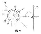
図1Aおよび1Bは、光をパターン生成要素110を通して投影させることによって構造化された光パターンを産出するように構成される、テクスチャ投影電球100の例示的構成を描写する。光線112は、光源102からパターン生成要素110の透過領域114を通して進行してもよい。光線112は、パターン生成要素110の非透過領域116によって遮断(例えば、吸収または反射)されてもよい。パターン生成要素110の透過領域114は、透過領域114を通して通過する光線112が1つ以上の画像118を外部表面120上に作成するように構成されてもよい。電球100は、電球エンクロージャ122によって封入されてもよい。電球エンクロージャ122は、少なくとも部分的に、透明または半透明であってもよい。例えば、エンクロージャ122は、略球状ガラスエンクロージャであってもよい。 FIGS. 1A and 1B depict an exemplary configuration of a
いくつかの実施形態では、パターン生成要素110は、エンクロージャ122の一部を備える。例えば、パターン生成要素110は、エンクロージャ122の透過および非透過領域を含んでもよい。エンクロージャ122の透過および非透過領域は、非透過材料をそうでなければ透過性であるエンクロージャ122(例えば、クリアガラスまたは他の透明もしくは半透明材料)の内側または外側表面上に印刷または堆積させる等の方法によって産出されてもよい。他の実施形態では、パターン生成要素110は、エンクロージャ122と別個であってもよい。例えば、パターン生成要素110は、エンクロージャ122に隣接する、またはそこから離間される、光源102を囲繞する、エンクロージャであってもよい。 In some embodiments, the
パターン生成要素110は、電磁スペクトルの少なくとも一部に不透明である、種々の金属または他の材料のいずれかを含んでもよい。いくつかの実施形態では、パターン生成要素110の非透過領域116は、概して、光源102によって放出されるスペクトルの大部分または全ての波長に不透明であってもよい。他の実施形態では、パターン生成要素110の非透過領域116は、スペクトルの所望の部分に対してのみ、選択的に不透明であってもよい。例えば、非透過領域116は、赤外線波長に不透明であるが、可視光に透明である、「ホットミラー」材料または他の材料を含んでもよい一方、透過領域114は、赤外線および可視光の両方に透明なクリアガラスまたは他の材料を含んでもよい。したがって、可視光は、電球の表面全体を通して通過することができる一方、赤外線光は、透過領域114のみを通して通過してもよい。選択的透過および非透過領域114、116のそのような組み合わせは、部屋を可視光で照明し、通常の電球であるように見える一方、マシンビジョンデバイスによって検出可能であるが、ヒトの眼に不可視である、赤外線光の構造化された光パターンを投影させるように構成される、電球を産出することができる。 The
図1Aに描写される、テクスチャ投影電球100は、拡張光源102を含む一方、図1Bの電球100は、理想的点光源104を含む。点源104のサイズ(例えば、長さ、幅、断面積)は、電球のサイズに対して無視可能であるため、点源104は、拡張源102と異なる。拡張光源(例えば、白熱フィラメント)は、無視不可能なサイズを有する。例えば、拡張光源は、透過エンクロージャ122のサイズ(例えば、直径)のある割合である、サイズを有し得、その割合は、0.1、0.2、0.3、またはそれを上回る。点源104は、テクスチャ投影電球100において使用するために望ましくあり得る。図1Aに示されるように、拡張光源102からパターン生成要素110の透明領域114を通して投影する、光線112は、ある角度のアレイにおいて進行し、コンピュータビジョンシステムが検出することが困難であり得る、拡散画像118aをもたらし得る。点源104が、図1Bにおけるように使用される場合、パターン生成要素110の各透明領域114から出射する光線112は、同一角度(または1°、0.5°、0.1°、もしくはそれ未満等の非常に小範囲の角度)で進行し、実質的にコリメートされたビームをもたらし、より鮮鋭に定義された画像118bを作成し、これは、コンピュータビジョンシステムによってより容易に検出され得る。 The
電球のために使用される光源は、典型的には、テクスチャ投影用途に望ましくあり得る、点源ではなく、拡張光源である。例えば、白熱電球は、電球のサイズに対して実質的サイズを有し得る、フィラメントを有し、光は、フィラメントの大部分または全てによって放出され得る。発光ダイオードは、いくつかの白熱フィラメントより小さいが、依然として、典型的には、テクスチャ投影電球用途のための点光源104として機能するには大きすぎる、拡張光源である。したがって、テクスチャを電球状デバイスで投影させることは、拡張光源からの光を使用して点状光源を産出することが可能な要素によって、改良および/または促進され得る。点光源に近似させるための例示的システムおよび方法は、図2−4Iを参照して以下に議論される。 The light source used for a light bulb is typically an extended light source rather than a point source, which may be desirable for texture projection applications. For example, an incandescent light bulb may have a filament that may have a substantial size relative to the size of the light bulb, and light may be emitted by most or all of the filament. Light emitting diodes are smaller than some incandescent filaments, but are still typically extended light sources that are too large to function as a point
(積分点源)
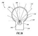
拡張光源によって放出される光は、拡張光源を積分器内に設置することによって、点光源に近似させるように誘導されることができる。図2は、電球100の中心において点光源に近似させるように構成される積分器106内に拡張光源102を含む、テクスチャ投影電球100を図式的に図示する。図1Aおよび1Bに描写される実施形態と同様に、テクスチャ投影電球100は、エンクロージャ122と、拡張光源102を囲繞する、パターン生成要素110(透過部分114および非透過部分116を含む)とを含む。電球100は、電球100が、電灯内の合致ソケットに接続される(例えば、機械的および電気的に)ことを可能にするように構成される(例えば、ねじ山付き金属基部を電灯内の対応するメス型ソケットの中に螺入することによって)、基部150を含む。例えば、電球100は、米国国家規格協会(ANSI)C81.63規格に説明されるような標準ゲージのねじ山付き基部150(例えば、E26)を有することができ、これは、有利には、電球状デバイスが従来の電灯と併用されることを可能にする。(Integral point source)
The light emitted by the extended light source can be guided to approximate a point light source by placing the extended light source in the integrator. FIG. 2 graphically illustrates a
電球100は、加えて、点光源に近似させるように、エンクロージャ122およびパターン生成要素110内に配置され、光源102を囲繞する、積分器106を含む。積分器106は、光源によって生成された光の全てまたは実質的に全てを内部反射および/または拡散させる。積分器106はさらに、積分器106から外への光線112の通過を可能にするように構成される、開口108を含む。開口108は、光積分器から退出し得る、唯一の場所である。したがって、小開口108は、光を点源と実質的に同一様式で放出し得る。例えば、開口の面積は、0.2、0.1、0.05、0.025、0.01、またはそれより小さい等、比較的に小ポート割合によって乗算される、積分器の面積と等しくてもよい。 The
積分器106は、光が反射され得る内部体積を定義する、球形、楕円形、立方体、三角錐、または任意の他の3次元形状等の任意の好適な形状であってもよい。積分器106の内部表面は、光源102によって放出される光の全てまたは実質的に全てを反射させるように選択されてもよい。いくつかの実施形態では、内部表面は、拡散反射表面(例えば、拡散、ランバート、または「艶消し」表面)であってもよい。拡散反射積分器106では、光源102から積分器106の内部表面に進行する光124は、種々の角度で散乱または反射され得る。他の実施形態では、積分器106の内部表面は、鏡面様式または拡散と鏡面反射の組み合わせにおいて光を反射させ得る。種々の実施形態では、所望の反射特性は、積分器106の内部表面を所望の様式で反射する材料(例えば、金属、艶出しもしくは艶消し塗料もしくは他の表面仕上げ、または同等物)でコーティングすることによって達成されてもよい、または積分器全体(またはその一部)が、所望の様式で反射する材料から作製されてもよい。いくつかの実施形態では、積分器106は、Ulbricht球、Coblentz球、Sumpnerボックス、もしくは内部拡散および/または反射を呈する他のデバイスであってもよい。積分器の例示的構成は、図4A−4Iを参照してより詳細に説明される。 The
いくつかの実施形態では、均一または実質的に均一輝度分布を積分器内で達成することが望ましくあり得、これは、実質的に均一光出力を開口108からもたらすことができ、それによって、図1Bに示される点光源104のように機能する。輝度分布の均一性は、比較的に高球乗数を伴う積分器106を使用することによって遂行されてもよい。積分器の球乗数Mは、光源によって放出される光子が開口108を通して逃散する前に積分器内で反射されるであろう、平均回数として推定されることができる。球乗数はまた、積分器の内部表面の反射率ρと、M=ρ/[1−ρ(1−f)]としての開口108の面積と積分器106の総面積の比である、ポート割合fとの観点から推定されることができる。高反射率(例えば、1に近似するρ)および比較的に小ポート割合に関して、乗数は、非常に大きくなり得、積分器の内側の輝度分布は、源102の輝度よりはるかに大きくなり得る。乗数が大きいほど、典型的には、積分器内の輝度のより優れた均一性を提供する。種々の実装では、積分器の内部の反射率は、0.8、0.9、0.95、0.98、または0.99を上回り得る。種々の実装では、ポート割合は、0.2、0.1、0.05、0.025、または0.01未満であり得る。いくつかの実施形態における好適に高球乗数は、5、10、15、20、またはそれを上回り得る。 In some embodiments, it may be desirable to achieve a uniform or substantially uniform luminance distribution within the integrator, which can result in a substantially uniform light output from the
球乗数は、非球状積分器106の挙動を特性評価するためにも等しく使用され得る。比較的に高球乗数を伴う積分器106では、積分器106内の任意の点における光は、比較的に均質であり得る。積分器106内の光が、比較的に均質である場合、開口108またはその近傍の光は、全ての方向において、均一輝度分布を有し得る。開口108から退出する光は、概して、開口108の場所における積分器106に対しての接線の平面128によって境界される半空間に閉じ込められるであろう。したがって、高球乗数を有する、積分器106は、開口108から実質的に等方性の半球状輝度分布を産出し得る。故に、図2に示される積分器106の内側の光源102は、図1Bに示される点源を有するテクスチャ電球100と同様に機能する。図2に示される例示的電球100は、有利には、図1Aに示される拡張光源のより拡散性のテクスチャと比較して、比較的により鮮鋭なテクスチャを産出することができる。 The ball multiplier can also be used equally to characterize the behavior of the
積分器106の内側の光源102は、白熱フィラメント、発光ダイオード(LED)、ガス放出要素、アーク灯、レーザダイオード、または任意の他のタイプの光源を含むことができる。光源102によって放出される光のスペクトルは、電磁スペクトルの可視および/または赤外線部分を含むことができる。例えば、光源は、約700nm〜約2,000nmの範囲またはその中の任意のサブ範囲内の光を出力する、赤外線LEDを含むことができる。赤外線光は、コンピュータビジョンシステム(例えば、拡張現実システム、コンピュータゲームシステム等)によって使用されるテクスチャを生成するために有利であり得る。可視光源(赤外線光を提供する、または別個の赤外線ソースと組み合わせて)の使用は、電球100がまた、コンピュータビジョンシステムのユーザのための可視光源としても使用されることを可能にすることができる。故に、そのような電球100は、環境のための従来の可視照明を提供する一方、また、コンピュータビジョンシステムによって視認可能な不可視(例えば、赤外線)テクスチャを提供することができる。 The
図2は、テクスチャ投影電球100を、中心に位置する光源102および積分器106を伴う、従来の略球状電球として描写するが、テクスチャ投影電球100の多くの他の配列および/または幾何学形状も、可能性として考えられる。例えば、図2および3A−3Dは、積分電球100内の1つ以上の積分器106の種々の例示的配列を図示する。図2の配列では、積分器106は、開口108が電球エンクロージャ122の球状部分の幾何学的中心またはその近傍にあるように位置する。開口108は、点源として機能するため、開口は、軸128に沿って電球100と交差する平面によって境界される半球内に実質的に均一輝度を提供し得る。 FIG. 2 depicts the
ここで図3A−3Dを参照すると、積分器106は、いくつかの実施形態では、エンクロージャ122の球状部分の幾何学的中心から離れるように位置してもよい。例えば、図3Aは、開口108が、エンクロージャ122の中心に向かって、かつ基部部分130から離れるように面するように、光源102および積分器106が、基部部分130内等のエンクロージャ122の周縁の近傍に位置する、電球100を描写する。図3Aの配列は、パターン生成要素110および電球エンクロージャ122のより大きい部分を通して、光線112の投影を可能にし得る。 Here with reference to FIGS. 3A-3D, the
いくつかの実施形態では、パターン投影面積は、複数の光源102および積分器106を単一電球100内に提供することによって増加されてもよい。例えば、図3Bに描写される電球100は、2つの光源102を含有し、それぞれ、開口108を有する、積分器106内に配置される。投影されたテクスチャを歪曲または分断し得る、重複輝度パターンを回避するためには、積分器106は、2つの積分器106の輝度境界平面128が略平行であるように、開口108が反対方向に面した状態で配向されてもよい。そのような配列は、小暗色領域132を2つの半空間の間に残し得、光は、開口108のいずれかからも投影されない。開口の場所は、構造化された光パターンの分断を回避するように、暗色領域132が、照明された空間のサイズに対して無視可能であるように選択されることができる。他の実施形態では、2つを上回る光源102および/または積分器106が、含まれることができる。 In some embodiments, the pattern projected area may be increased by providing a plurality of
他の実施形態では、パターン投影面積は、単一光源102を複数の開口108を有する単一積分器106内に提供することによって増加されてもよい。例えば、図3Cに描写される電球100は、1つの光源102を2つの開口108を有する球状積分器106内に含有する。2つの開口108は、直径方向に対向するため、2つの照明された半空間(平面128によって境界される)は、上記に図3Bを参照して説明されるように、交差せず、小暗色領域132を残す。第2の開口108は、光が積分器106の内部から逃散するための付加的場所を提供し、それによって、積分器106の球乗数を減少させ得ることに留意されたい。 In other embodiments, the pattern projection area may be increased by providing a single
いくつかの実施形態では、電球エンクロージャ122は、球状または非球状であってもよい。例えば、図3Dに描写されるテクスチャ投影電球100は、非透過半径方向側部分および円周方向透過部分を含む、投光照明タイプエンクロージャ122を有する。投光照明タイプエンクロージャ122では、パターン生成要素110は、投光照明の透過部分に沿って配置されてもよい。種々の実施形態では、電球エンクロージャの任意の他の好適な形状は、構造化された光パターンを所望の面積に投影するために使用されてもよい。非球状電球エンクロージャ122はまた、本明細書に説明される1つ以上の光源102および積分器106の任意の配列を用いて実装されてもよい。 In some embodiments, the
図2−3Dは、各積分器106を単一拡張光源102を囲繞する球状積分器として描写するが、積分器106および光源102の多くの他の配列および/または幾何学形状も、可能性として考えられる。ここで図4A−4Iを参照すると、種々の構成の拡張光源102および積分器106が、説明されるであろう。図4A−4Iに描写される構成のそれぞれならびに描写される構成の変形例は、図2−3Dを参照して描写および説明されるテクスチャ投影電球内にも等しく実装されることができる。 FIG. 2-3D describes each
一実施例では、図4Aは、楕円形積分器106を描写し、光源102および開口108は、上記に説明される光源および積分器に一致する。光源102は、積分器106内で心合されてもよい、または積分器106の内部空間内のいずれかの場所に位置してもよい。開口108は、楕円形の短軸の近傍、楕円形の長軸の近傍、または積分器106の外部に沿った任意の他の場所に位置してもよい。例えば、図4Gに描写される楕円形積分器106は、積分器106の中心から離れるように位置する、光源102と、楕円形の長軸に沿って位置する、開口108とを含む。いくつかの実施形態では、積分器106は、1つを上回る開口を含んでもよい。 In one embodiment, FIG. 4A depicts an
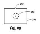
別の例示的構成では、図4Bは、長方形断面を有する、積分器106を描写する。例えば、図4Bの積分器106は、長方形または多角形断面を伴う、長方形角柱、円筒形、または他の3次元形状であってもよい。図4Aに描写される積分器と同様に、積分器106は、光源102を含有し、開口108を含む。光源102は、積分器106内で心合されてもよい、または積分器106の内部空間内のいずれかの場所に位置してもよい。開口は、長方形の辺に沿って、角に、または積分器の外部に沿った任意の他の場所に位置してもよい。例えば、図4Fに描写される長方形積分器106は、積分器の中心から離れるように位置する、光源102と、長方形の角の近傍に位置する、開口108とを含む。いくつかの実施形態では、積分器106は、1つを上回る開口を含んでもよい。 In another exemplary configuration, FIG. 4B depicts an
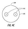
いくつかの実施形態では、積分器106は、1つを上回る光源102を含有してもよい。例えば、図4Cに描写される積分器106は、2つの拡張光源102を含有する。1つを上回る光源102が、積分器106内に含まれ、例えば、テクスチャ投影電球の輝度を増加させてもよい。いくつかの実施形態では、光源102は、積分器によって組み合わせられるようなその光が所望のスペクトルプロファイルを有し得るように、異なる輝度スペクトルを有する源であってもよい。例えば、1つの源は、主に、可視光を放出してもよく、他の源は、主に、赤外線光を放出してもよい。図4Cの積分器106は、円形断面を有するように描写されるが、積分器106内の複数の光源102の任意の配列は、上記に説明されるように、非球状積分器を用いて実装されてもよいことを理解されるであろう。 In some embodiments, the
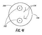
ここで図4Dおよび4Eを参照すると、いくつかの実施形態はさらに、1つ以上のバッフル134または他の光遮断構造を積分器106内に含み、開口108における積分器106から出射する光の均一性を増加させてもよい。バッフルの不在下では、光学経路は、直接、光源102から開口108に存在し得る。直接、光源102から開口108に進行する光は、積分器106の拡散反射内側表面と相互作用せずに、開口108に到達し得、それによって、開口における光のそうでなければ均一な分布を分断し得る。したがって、1つ以上のバッフル134が、光源102と開口108との間の直接経路を遮断するように、積分器106内に含まれてもよい。いくつかの実施形態では、1つ以上のバッフル134は、積分器106の内部表面と同一拡散もしくは鏡面材料または類似材料から作成される、またはそれでコーティングされてもよい。いくつかの実施形態では、光源102に面したバッフル134の側は、開口108に面したバッフル134の側と異なるコーティングを有してもよい(例えば、片側は、鏡面反射であってもよく、片側は、拡散反射であってもよい)。例えば、図4Dは、拡張光源102と、光源102と開口108との間に位置し、光が、直接、光源102から開口108に進行しないように防止する、バッフル134とを含有する、積分器106を描写する。同様に、図4Eは、2つの拡張光源102と、2つのバッフル134とを含有する、積分器106を描写し、各バッフル134は、光源102と開口108との間に位置し、光が、直接、光源102から開口108に進行しないように防止する。さらに、バッフル134は、図4Dおよび4Eに描写されるように、略線形断面であってもよい、もしくは図4Hおよび4Iに描写されるバッフル134等の曲線および/または角度を含む、他の形状を有してもよい。 Referring here to FIGS. 4D and 4E, some embodiments further include one or
図4Dおよび4Eの積分器106は、円形断面を有するように描写されるが、積分器106内の1つ以上の光源102およびバッフル134の任意の配列が、上記に説明されるように、非球状積分器を用いて実装されてもよい。加えて、いくつかの実施形態は、積分器106の外側に位置する、1つ以上の拡張光源102を組み込んでもよく、光は、源102から付加的開口を通して積分器106に進入する。図2−4Eに描写される実施形態の要素、配列、および他の特徴は、相互に独立して使用されてもよい。したがって、図2−4Eのいずれかを参照して描写および/または説明される要素、配列、もしくは他の特徴の任意の組み合わせまたは副次的組み合わせが、本開示の精神もしくは範囲から逸脱することなく、実装されてもよい。 The
(3Dディスプレイ)
上記に説明される構造化された光投影システムおよび方法は、種々のマシンビジョン用途のために実装されてもよい。例えば、仮想現実(VR)または拡張現実(AR)システムでは、ウェアラブルデバイスは、ユーザの周囲の世界内のオブジェクトまたは境界の存在を検出するように、本明細書のいずれかに説明されるパターン等の構造光パターンを検出するように構成されてもよい。例えば、電球100の実施形態は、ユーザの環境内の電灯に接続され、ARシステム(またはゲーム用システム)と関連付けられたコンピュータビジョンシステムによって検出および処理のために、テクスチャを環境内の表面およびオブジェクト上に投影するために使用されることができる。検出されたオブジェクトまたは境界に基づいて、ウェアラブルシステムは、世界の3次元レンダリングを装着者に投影する、または世界からの光が装着者の眼に通過することを可能にする一方、仮想オブジェクトを装着者の世界のビューに追加すること等によって、VRまたはAR体験を提供してもよい。いくつかの実装では、装着者は、仮想オブジェクトが装着者によって視認可能な実オブジェクトと相互作用する、AR体験を提示されてもよく、その体験は、複合現実とも称される。前述のようなテクスチャ投影電球と互換性があるディスプレイシステムの例示的実施形態が、ここで説明されるであろう。(3D display)
The structured light projection systems and methods described above may be implemented for various machine vision applications. For example, in a virtual reality (VR) or augmented reality (AR) system, a wearable device may detect the presence of an object or boundary in the world around the user, such as a pattern described herein. It may be configured to detect the structural light pattern of. For example, an embodiment of the
3次元(3D)ディスプレイが、真の深度感覚、より具体的には、表面深度のシミュレートされた感覚を産出するために、ディスプレイの視野内の点毎に、その仮想深度に対応する遠近調節応答を生成することが望ましくあり得る。ディスプレイ点に対する遠近調節応答が、収束および立体視の両眼深度キューによって判定されるようなその点の仮想深度に対応しない場合、ヒトの眼は、遠近調節衝突を体験し、不安定な結像、有害な眼精疲労、頭痛、および遠近調節情報の不在下では、表面深度のほぼ完全な欠如をもたらし得る。 A three-dimensional (3D) display provides a true depth sensation, more specifically, a perspective corresponding to its virtual depth at each point in the display's field of view to produce a simulated sensation of surface depth. It may be desirable to generate a response. If the accommodation response to a display point does not correspond to the virtual depth of that point as determined by the convergence and stereoscopic binocular depth cues, the human eye experiences an accommodation collision and an unstable imaging. In the absence of adverse eye strain, headache, and accommodation information, it can result in an almost complete lack of surface depth.
VRおよびAR体験は、複数の深度平面に対応する画像が視認者に提供されるディスプレイを有する、ディスプレイシステムによって提供されることができる。画像は、深度平面毎に異なってもよく(例えば、場面またはオブジェクトの若干異なる提示を提供する)、視認者の眼によって別個に集束され、それによって、異なる深度平面上に位置する場面に関する異なる画像特徴に合焦させるために要求される眼の遠近調節に基づいて、または合焦からずれている異なる深度平面上の異なる画像特徴を観察することに基づいて、ユーザに深度キューを提供することに役立ち得る。本明細書のいずれかに議論されるように、そのような深度キューは、信用できる深度の知覚を提供する。 The VR and AR experience can be provided by a display system having a display in which images corresponding to multiple depth planes are provided to the viewer. The images may be different for each depth plane (eg, provide a slightly different presentation of the scene or object) and are separately focused by the eyes of the viewer, thereby different images of the scene located on different depth planes. To provide the user with a depth queue based on the accommodation required to focus the feature or on observing different image features on different depth planes that are out of focus. Can be useful. As discussed in any of the specification, such depth cues provide a credible perception of depth.
図5は、ウェアラブルディスプレイシステム500の実施例を図示する。ウェアラブルディスプレイシステム500は、ディスプレイ62と、ディスプレイ62の機能をサポートするための種々の機械的ならびに電子的モジュールおよびシステムとを含む。ディスプレイ62は、フレーム64に結合されてもよく、これは、ディスプレイシステムユーザ、装着者、または視認者60によって装着可能であり、ディスプレイ62をユーザ60の眼の正面に位置付けるように構成される。ディスプレイシステム500は、装着者の頭部上に装着される、頭部搭載型ディスプレイ(HMD)を備えることができる。拡張現実デバイス(ARD)は、ウェアラブルディスプレイシステム500を含むことができる。いくつかの実施形態では、スピーカ66が、フレーム64に結合され、ユーザの外耳道に隣接して位置付けられる(いくつかの実施形態では、示されない別のスピーカが、ユーザの他方の外耳道に隣接して位置付けられ、ステレオ/成形可能音響制御を提供する)。ディスプレイシステム500は、装着者の周囲の環境内の世界を観察する、外向きに面した結像システムを含むことができる(例えば、図7に示される結像システム502参照)。ディスプレイシステム500はまた、内向きに面した結像システムを含むことができ、これは、装着者の眼移動を追跡することができる(例えば、図7に示される結像システム500参照)。内向きに面した結像システムは、一方の眼の移動または両方の眼の移動のいずれかを追跡してもよい。いくつかの実施形態では、ディスプレイシステム500はまた、外向きに面した結像システムを含むことができ、これは、装着者の周囲の世界を結像し、装着者の近傍の表面上に投影される構造化された光パターンを検出することができる。ディスプレイ62は、有線導線または無線接続等によって、フレーム64に固定して取り付けられる、ユーザによって装着されるヘルメットもしくは帽子に固定して取り付けられる、ヘッドホンに内蔵される、または別様にユーザ60に(例えば、バックパック式構成において、ベルト結合式構成において)可撤式に取り付けられる等、種々の構成において搭載され得る、ローカルデータ処理モジュール71に動作可能に結合68されることができる。 FIG. 5 illustrates an embodiment of the
ローカル処理およびデータモジュール71は、ハードウェアプロセッサならびに不揮発性メモリ(例えば、フラッシュメモリ)等のデジタルメモリを備えてもよく、その両方は、データの処理、キャッシング、および記憶を補助するために利用され得る。データは、(a)画像捕捉デバイス(例えば、カメラ)、マイクロホン、慣性測定ユニット(IMU)、加速度計、コンパス、全地球測位システム(GPS)ユニット、無線デバイス、および/またはジャイロスコープ等の(例えば、フレーム64に動作可能に結合される、または別様にユーザ60に取り付けられ得る)センサから捕捉されるデータ、および/または(b)場合によっては処理もしくは読出後にディスプレイ62の通過のために、遠隔処理モジュール72および/または遠隔データリポジトリ74を使用して取得ならびに/もしくは処理されるデータを含んでもよい。ローカル処理およびデータモジュール71は、これらの遠隔モジュールが、ローカル処理およびデータモジュール71へのリソースとして利用可能であるように、通信リンク76および/または78によって、有線または無線通信リンクを介して等、遠隔処理モジュール72および/または遠隔データリポジトリ74に動作可能に結合されてもよい。加えて、遠隔処理モジュール72および遠隔データリポジトリ74は、相互に動作可能に結合されてもよい。 The local processing and
いくつかの実施形態では、遠隔処理モジュール72は、データおよび/または画像情報を分析ならびに処理するように構成される、1つ以上のハードウェアプロセッサを備えてもよい。いくつかの実施形態では、遠隔データリポジトリ74は、デジタルデータ記憶設備を備え得、これは、「クラウド」リソース構成におけるインターネットまたは他のネットワーキング構成を通して利用可能であってもよい。いくつかの実施形態では、全てのデータが、記憶され、全ての算出が、ローカル処理およびデータモジュールにおいて実施され、遠隔モジュールからの完全に自律的な使用を可能にする。 In some embodiments, the
ヒト視覚系は、複雑であり、深度の現実的知覚を提供することは、困難である。理論によって限定されるわけではないが、オブジェクトの視認者は、両眼離反運動および遠近調節の組み合わせに起因して、オブジェクトを3次元として知覚し得ると考えられる。相互に対する2つの眼の両眼離反運動(例えば、眼の視線を収束させ、オブジェクト上に固定させるための相互に向かって、またはそこから離れるような瞳の転動運動)は、眼の水晶体の集束(または「遠近調節」)と密接に関連付けられる。通常条件下では、眼の水晶体の焦点を変化させる、または眼を遠近調節し、1つのオブジェクトから異なる距離における別のオブジェクトに焦点を変化させることは、「遠近調節−両眼離反運動反射」として知られる関係下、自動的に、両眼離反運動における合致する変化を同一距離に生じさせるであろう。同様に、両眼離反運動における変化は、通常条件下、遠近調節における合致する変化を誘起するであろう。遠近調節と両眼離反運動との間のより良好な合致を提供するディスプレイシステムは、3次元画像のより現実的または快適なシミュレーションを形成し得る。 The human visual system is complex and it is difficult to provide a realistic perception of depth. Although not limited by theory, it is believed that the viewer of the object may perceive the object as three-dimensional due to the combination of binocular detachment and accommodation. The binocular eccentric movement of the two eyes with respect to each other (eg, the rolling movement of the pupil toward or away from each other to converge and fix the line of sight on the object) is the crystalline lens of the eye. Closely associated with focusing (or "accommodation"). Under normal conditions, changing the focus of the crystalline lens of the eye, or adjusting the perspective of the eye and changing the focus from one object to another at different distances, is referred to as "accommodation-accommodation-binocular reflex". Under known relationships, it will automatically produce matching changes in binocular reflex movement at the same distance. Similarly, changes in binocular detachment will induce matching changes in accommodation under normal conditions. A display system that provides a better match between accommodation and binocular detachment movement can form a more realistic or comfortable simulation of a 3D image.
図6は、複数の深度平面を使用して3次元画像をシミュレートするためのアプローチの側面を図示する。図6を参照すると、z−軸上の眼302および304からの種々の距離におけるオブジェクトは、それらのオブジェクトが合焦するように、眼302および304によって遠近調節される。眼302および304は、特定の遠近調節された状態をとり、オブジェクトをz−軸に沿った異なる距離に合焦させる。その結果、特定の遠近調節された状態は、特定の深度平面におけるオブジェクトまたはオブジェクトの一部が、眼がその深度平面に対して遠近調節された状態にあるとき、合焦するように、関連付けられた焦点距離を有して、深度平面306のうちの特定の1つと関連付けられると言え得る。いくつかの実施形態では、3次元画像は、眼302および304毎に、画像の異なる提示を提供することによって、また、深度平面のそれぞれに対応する画像の異なる提示を提供することによって、シミュレートされてもよい。例証を明確にするために、別個であるように示されるが、眼302および304の視野は、例えば、z−軸に沿った距離が増加するにつれて、重複し得ることを理解されたい。加えて、例証を容易にするために、平坦であるように示されるが、深度平面の輪郭は、深度平面内の全ての特徴が特定の遠近調節された状態において眼と合焦するように、物理的空間内で湾曲されてもよいことを理解されたい。理論によって限定されるわけではないが、ヒトの眼は、典型的には、深度知覚を提供するために、有限数深度面を解釈し得ると考えられる。その結果、知覚される深度の高度に真実味のあるシミュレーションが、これらの限定された数の深度面のそれぞれに対応する画像の異なる表現を眼に提供することによって達成され得る。 FIG. 6 illustrates aspects of an approach for simulating a 3D image using multiple depth planes. Referring to FIG. 6, objects at various distances from the
(導波管スタックアセンブリ)
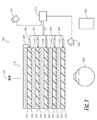
図7は、画像情報をユーザに出力するための導波管スタックの実施例を図示する。ディスプレイシステム700は、複数の導波管182、184、186、188、190を使用して、3次元知覚を眼/脳に提供するために利用され得る、導波管のスタックまたはスタックされた導波管アセンブリ178を含む。いくつかの実施形態では、ディスプレイシステム700は、図2のシステム700に対応してもよく、図4は、そのシステム700のいくつかの部分をより詳細に図式的に示す。例えば、いくつかの実施形態では、導波管アセンブリ178は、図2のディスプレイ62の中に統合されてもよい。(Waveguide stack assembly)
FIG. 7 illustrates an example of a waveguide stack for outputting image information to a user. The
図4を継続して参照すると、導波管アセンブリ178はまた、複数の特徴198、196、194、192を導波管の間に含んでもよい。いくつかの実施形態では、特徴198、196、194、192は、レンズであってもよい。導波管182、184、186、188、190および/または複数のレンズ198、196、194、192は、種々のレベルの波面曲率または光線発散を伴って、画像情報を眼に送信するように構成されてもよい。各導波管レベルは、特定の深度平面と関連付けられてもよく、その深度平面に対応する画像情報を出力するように構成されてもよい。画像投入デバイス200、202、204、206、208は、それぞれ、眼304に向かって出力するために、各個別の導波管を横断して入射光を分散させるように構成され得る、導波管182、184、186、188、190の中に画像情報を投入するために利用されてもよい。光は、画像投入デバイス200、202、204、206、208の出力表面から出射し、導波管182、184、186、188、190の対応する入力縁の中に投入される。いくつかの実施形態では、光の単一ビーム(例えば、コリメートされたビーム)が、各導波管の中に投入され、特定の導波管と関連付けられる深度面に対応する特定の角度(および発散量)において眼304に向かって指向される、クローン化されたコリメートビームの場全体を出力してもよい。 With reference to FIG. 4, the
いくつかの実施形態では、画像投入デバイス200、202、204、206、208は、それぞれ、それぞれの対応する導波管182、184、186、188、190の中に投入するための画像情報を産出する、離散ディスプレイである。いくつかの他の実施形態では、画像投入デバイス200、202、204、206、208は、例えば、1つ以上の光学導管(光ファイバケーブル等)を介して、画像情報を画像投入デバイス200、202、204、206、208のそれぞれに送出し得る、単一の多重化されたディスプレイの出力端である。 In some embodiments, the
コントローラ210が、スタックされた導波管アセンブリ178および画像投入デバイス200、202、204、206、208の動作を制御する。いくつかの実施形態では、コントローラ210は、導波管182、184、186、188、190への画像情報のタイミングおよび提供を調整する、プログラミング(例えば、非一過性コンピュータ可読媒体内の命令)を含む。いくつかの実施形態では、コントローラは、単一一体型デバイスまたは有線もしくは無線通信チャネルによって接続される分散型システムであってもよい。コントローラ210は、いくつかの実施形態では、処理モジュール71または72(図2に図示される)の一部であってもよい。 The
導波管182、184、186、188、190は、全内部反射(TIR)によって、光を各個別の導波管内で伝搬させるように構成されてもよい。導波管182、184、186、188、190はそれぞれ、主要上部および底部表面と、それらの主要上部と底部表面との間に延在する縁とを伴う、平面である、または別の形状(例えば、湾曲)を有してもよい。図示される構成では、導波管182、184、186、188、190はそれぞれ、光を再指向させ、各個別の導波管内で伝搬させ、導波管から外へ画像情報を眼304に出力することによって、光を導波管から外へ抽出するように構成される、光抽出光学要素282、284、286、288、290を含んでもよい。抽出された光はまた、外部結合光と称され得、光抽出光学要素はまた、外部結合光学要素と称され得る。抽出された光のビームは、導波管によって、導波管内で伝搬する光が光再指向要素に衝打する場所に出力される。光抽出光学要素282、284、286、288、290は、例えば、反射および/または回折光学特徴であってもよい。説明を容易にし、図面を明確にするために、導波管182、184、186、188、190の底部主要表面に配置されて図示されるが、いくつかの実施形態では、光抽出光学要素282、284、286、288、290は、上部および/または底部主要表面に配置されてもよい、ならびに/もしくは直接導波管182、184、186、188、190の容積内に配置されてもよい。いくつかの実施形態では、光抽出光学要素282、284、286、288、290は、透明基板に取り付けられ、導波管182、184、186、188、190を形成する、材料の層内に形成されてもよい。いくつかの他の実施形態では、導波管182、184、186、188、190は、モノリシック材料片であってもよく、光抽出光学要素282、284、286、288、290は、その材料片の表面上および/または内部に形成されてもよい。 The
図4を継続して参照すると、本明細書に議論されるように、各導波管182、184、186、188、190は、光を出力し、特定の深度平面に対応する画像を形成するように構成される。例えば、眼の最近傍の導波管182は、そのような導波管182の中に投入されるにつれて、コリメートされた光を眼304に送達するように構成されてもよい。コリメートされた光は、光学無限遠焦点面を表し得る。次の上方の導波管184は、眼304に到達し得る前に、第1のレンズ192(例えば、負のレンズ)を通して通過する、コリメートされた光を送出するように構成されてもよい。第1のレンズ192は、眼/脳が、その次の上方の導波管184から生じる光が光学無限遠から眼304に向かって内向きにより近い第1の焦点面から生じるように解釈するように、若干の凸面波面曲率を生成するように構成されてもよい。同様に、第3の上方の導波管186は、眼304に到達する前に、その出力光を第1のレンズ192および第2のレンズ194の両方を通して通過させる。第1および第2のレンズ192ならびに194の組み合わせられた屈折力は、眼/脳が、第3の導波管186から生じる光が次の導波管184からの光であった光学無限遠から人物に向かって内向きにさらにより近い第2の焦点面から生じるように解釈するように、波面曲率の別の増分量を生成するように構成されてもよい。 With reference to FIG. 4, as discussed herein, each
他の導波管層(例えば、導波管188、190)およびレンズ(例えば、レンズ196、198)も同様に、スタック内の最高導波管190を用いて、人物に最も近い焦点面を表す集約焦点力のために、その出力をそれと眼との間のレンズの全てを通して送出するように構成される。スタックされた導波管アセンブリ178の他側の世界144から生じる光を視認/解釈するとき、レンズ198、196、194、192のスタックを補償するために、補償レンズ層180が、スタックの上部に配置され、下方のレンズスタック198、196、194、192の集約力を補償してもよい。そのような構成は、利用可能な導波管/レンズ対と同じ数の知覚される焦点面を提供する。導波管の光抽出光学要素およびレンズの集束側面は両方とも、静的であってもよい(例えば、動的または電気活性ではない)。いくつかの代替実施形態では、いずれかまたは両方とも、電気活性特徴を使用して、動的であってもよい。 Other waveguide layers (eg,
ディスプレイシステム700は、世界144の一部を結像する、外向きに面した結像システム502(例えば、デジタルカメラ)を含むことができる。世界144の本部分は、視野(FOV)と称され得、結像システム502は、FOVカメラとも称される。視認者による視認または結像のために利用可能な領域全体は、動眼視野(FOR)と称され得る。いくつかのHMD実装では、FORは、HMDの装着者の周囲の立体角の実質的に全てを含んでもよく、これは、装着者が、その頭部および眼を移動させ、装着者を囲繞する(装着者の正面、背面、上方、下方、または側面の)オブジェクトを見ることができるためである。外向きに面した結像システム502から取得される画像は、装着者によって行われるジェスチャ(例えば、手または指ジェスチャ)を追跡する、装着者の正面の世界144内のオブジェクトを検出する等のために使用されることができる。 The
ディスプレイシステム700は、ユーザ入力デバイス504を含むことができ、それによって、ユーザは、コマンドをコントローラ210に入力し、システム700と相互作用することができる。例えば、ユーザ入力デバイス504は、トラックパッド、タッチスクリーン、ジョイスティック、多重自由度(DOF)コントローラ、容量感知デバイス、ゲームコントローラ、キーボード、マウス、指向性パッド(D−パッド)、ワンド、触知デバイス、トーテム(例えば、仮想ユーザ入力デバイスとして機能する)等を含むことができる。ある場合には、ユーザは、指(例えば、親指)を使用して、タッチセンサ式入力デバイスを押下またはスワイプし、入力をシステム700に提供してもよい(例えば、ユーザ入力をシステム700によって提供されるユーザインターフェースに提供するため)。ユーザ入力デバイス504は、システム700の使用の間、ユーザの手によって保持されてもよい。ユーザ入力デバイス504は、ディスプレイシステム700と有線または無線通信することができる。 The
図4を継続して参照すると、光抽出光学要素282、284、286、288、290は、光をその個別の導波管から外へ再指向し、かつ導波管と関連付けられた特定の深度平面のための適切な量の発散またはコリメーションを用いて、本光を出力することの両方を行うように構成されてもよい。その結果、異なる関連付けられた深度平面を有する導波管は、関連付けられた深度平面に応じて異なる量の発散を伴う光を出力する、異なる構成の光抽出光学要素を有してもよい。いくつかの実施形態では、本明細書に議論されるように、光抽出光学要素282、284、286、288、290は、光を具体的角度で出力するように構成され得る、立体または表面特徴であってもよい。例えば、光抽出光学要素282、284、286、288、290は、立体ホログラム、表面ホログラム、および/または回折格子であってもよい。回折格子等の光抽出光学要素は、2015年6月25日に公開された米国特許公開第2015/0178939号(参照することによってその全体として本明細書に組み込まれる)に説明されている。いくつかの実施形態では、特徴198、196、194、192は、レンズではなくてもよい。むしろ、それらは、単に、スペーサであってもよい(例えば、空気間隙を形成するためのクラッディング層および/または構造)。 With reference to FIG. 4, the
いくつかの実施形態では、光抽出光学要素282、284、286、288、290は、回折パターンを形成する回折特徴、すなわち、「回折光学要素」(本明細書では、「DOE」とも称される)である。好ましくは、DOEは、ビームの光の一部のみが、DOEの各交差点を用いて、眼304に向かって偏向される一方、残りが、全内部反射を介して、導波管を通して移動し続けるように、比較的に低回折効率を有する。画像情報を搬送する光は、したがって、複数の場所において導波管から出射する、いくつかの関連出射ビームに分割され、その結果、導波管内でバウンスする本特定のコリメートされたビームに関して、眼304に向かって非常に均一な出射放出パターンとなる。 In some embodiments, the
いくつかの実施形態では、1つ以上のDOEは、能動的に回折する「オン」状態と有意に回折しない「オフ」状態との間で切替可能であってもよい。例えば、切替可能なDOEは、微小液滴がホスト媒体中に回折パターンを構成する、ポリマー分散液晶の層を備えてもよく、微小液滴の屈折率は、ホスト材料の屈折率と実質的に合致するように切り替えられることができる(その場合、パターンは、入射光を著しく回折しない)、または微小液滴は、ホスト媒体のものに合致しない屈折率に切り替えられることができる(その場合、パターンは、入射光を能動的に回折する)。 In some embodiments, the one or more DOEs may be switchable between an actively diffracting "on" state and a significantly non-diffractive "off" state. For example, the switchable DOE may include a layer of polymer dispersed liquid crystal in which the microdroplets form a diffraction pattern in the host medium, the index of refraction of the microdroplets being substantially the index of refraction of the host material. It can be switched to match (in which case the pattern does not significantly diffract the incident light), or the microdroplets can be switched to a refractive index that does not match that of the host medium (in which case the pattern). Actively diffracts incident light).
いくつかの実施形態では、深度平面および/または被写界深度の数ならびに分布は、視認者の眼の瞳孔サイズおよび/または配向に基づいて、動的に変動されてもよい。いくつかの実施形態では、ディスプレイシステム700はまた、内向きに面した結像システム(例えば、デジタルカメラ)500を含み、これは、眼移動および顔移動等の装着者の移動を観察する。内向きに面した結像システム500(例えば、デジタルカメラ)が、眼304の画像を捕捉し、眼304の瞳孔のサイズおよび/または配向を判定するために使用されてもよい。内向きに面した結像システム500は、装着者60が見ている方向(例えば、眼姿勢)を判定する際に使用するため、または装着者のバイオメトリック識別(例えば、虹彩識別を介して)の画像を取得するために使用されることができる。いくつかの実施形態では、内向きに面した結像システム500は、フレーム64に取り付けられてもよく(図2に図示されるように)、処理モジュール71および/または72と電気通信してもよく、これは、カメラ500からの画像情報を処理し、例えば、ユーザ60の眼の瞳孔直径および/または配向を判定してもよい。いくつかの実施形態では、少なくとも1つのカメラ500が、各眼を結像するために利用され、各眼の瞳孔サイズおよび/または眼姿勢を独立して判定し、それによって、各眼への画像情報の提示がその眼に動的に調整されることを可能にしてもよい。いくつかの他の実施形態では、片眼304のみの瞳孔直径および/または配向が、判定され(例えば、対の眼あたり単一結像システム500のみを使用して)、本眼に関して判定された眼特徴は、視認者60の他方の眼に対して類似すると仮定される。内向きに面した結像システム500から取得される画像は、HMDによって閉塞される装着者の顔の領域を置換するための画像を取得するために使用されてもよく、これは、テレプレゼンスセッションの間、第1の発呼者に第2の発呼者の閉塞されていない顔が見えるように使用されることができる。ディスプレイシステム700はまた、IMU、加速度計、ジャイロスコープ等のセンサを使用して、頭部姿勢(例えば、頭部位置または頭部配向)を判定してもよい。頭部の姿勢は、単独で、または視線方向と組み合わせて、仮想オブジェクトを選択し、移動させるために使用されてもよい。 In some embodiments, the number and distribution of depth planes and / or depths of field may be dynamically varied based on the pupil size and / or orientation of the viewer's eye. In some embodiments, the
被写界深度は、視認者の瞳孔サイズと反比例して変化してもよい。その結果、視認者の眼の瞳孔のサイズが減少するにつれて、被写界深度は、その平面の場所が眼の焦点深度を越えるため判別不能である1つの平面が、判別可能となり、瞳孔サイズの低減および被写界深度の相当する増加に伴って、より合焦して現れ得るように増加する。同様に、異なる画像を視認者に提示するために使用される、離間される深度平面の数は、減少された瞳孔サイズに伴って減少されてもよい。例えば、視認者は、一方の深度平面から他方の深度平面への眼の遠近調節を調節せずに、第1の深度平面および第2の深度平面の両方の詳細を1つの瞳孔サイズにおいて明確に知覚することが可能ではない場合がある。しかしながら、これらの2つの深度平面は、同時に、遠近調節を変化させずに、別の瞳孔サイズにおいてユーザに合焦するには十分であり得る。 The depth of field may change in inverse proportion to the pupil size of the viewer. As a result, as the size of the pupil of the viewer's eye decreases, the depth of field becomes discriminable for one plane that is indistinguishable because the location of that plane exceeds the depth of focus of the eye, and the pupil size becomes larger. With a reduction and a corresponding increase in depth of field, it increases to be more in focus and appear. Similarly, the number of separated depth planes used to present different images to the viewer may be reduced with the reduced pupil size. For example, the viewer can clearly see the details of both the first and second depth planes in one pupil size without adjusting the accommodation of the eye from one depth plane to the other. It may not be possible to perceive. However, these two depth planes may be sufficient to focus on the user at different pupil sizes at the same time without changing the accommodation.
いくつかの実施形態では、ディスプレイシステムは、瞳孔サイズおよび/または配向の判定に基づいて、もしくは特定の瞳孔サイズおよび/または配向を示す電気信号の受信に応じて、画像情報を受信する導波管の数を変動させてもよい。例えば、ユーザの眼が、2つの導波管と関連付けられた2つの深度平面間を区別不能である場合、コントローラ210は、これらの導波管のうちの1つへの画像情報の提供を停止するように構成またはプログラムされてもよい。有利には、これは、システムへの処理負担を低減させ、それによって、システムの応答性を増加させ得る。導波管のためのDOEがオンおよびオフ状態間で切替可能である実施形態では、DOEは、導波管が画像情報を受信するとき、オフ状態に切り替えられてもよい。 In some embodiments, the display system receives image information based on a determination of pupil size and / or orientation, or in response to an electrical signal indicating a particular pupil size and / or orientation. The number of may vary. For example, if the user's eye is indistinguishable between the two depth planes associated with the two waveguides, the
いくつかの実施形態では、出射ビームに視認者の眼の直径未満の直径を有するという条件を満たさせることが望ましくあり得る。しかしながら、本条件を満たすことは、視認者の瞳孔のサイズの変動性に照らして、困難であり得る。いくつかの実施形態では、本条件は、視認者の瞳孔のサイズの判定に応答して出射ビームのサイズを変動させることによって、広範囲の瞳孔サイズにわたって満たされる。例えば、瞳孔サイズが減少するにつれて、出射ビームのサイズもまた、減少し得る。いくつかの実施形態では、出射ビームサイズは、可変開口を使用して変動されてもよい。 In some embodiments, it may be desirable to satisfy the condition that the emitted beam has a diameter less than the diameter of the viewer's eye. However, satisfying this condition can be difficult in light of the variability in the size of the pupil of the viewer. In some embodiments, this condition is met over a wide range of pupil sizes by varying the size of the emitted beam in response to determining the size of the pupil of the viewer. For example, as the pupil size decreases, so does the size of the emitted beam. In some embodiments, the emitted beam size may vary using a variable aperture.
(付加的側面)
第1の側面では、テクスチャ投影電球が、説明される。テクスチャ投影電球は、赤外線光を産出するように構成される、白熱フィラメントと、白熱フィラメントを封入する積分球と、積分球を囲繞する電球エンクロージャとを備える。積分球は、拡散反射内部表面と、光が積分球から外へ通過することを可能にするように構成される、開口とを備える。エンクロージャは、赤外線光に透過性の1つ以上の領域と、赤外線光に不透明な1つ以上の領域とを備える。1つ以上の透過領域は、コンピュータビジョンシステムによって検出可能な赤外線光の構造化された光パターンを投影するように構成される。(Additional aspect)
In the first aspect, a texture projection bulb is described. The textured projection bulb comprises an incandescent filament configured to produce infrared light, an integrating sphere that encloses the incandescent filament, and a bulb enclosure that surrounds the integrating sphere. The integrating sphere comprises an internal surface of diffuse reflection and an aperture configured to allow light to pass out of the integrating sphere. The enclosure comprises one or more areas that are transparent to infrared light and one or more areas that are opaque to infrared light. One or more transmission regions are configured to project a structured light pattern of infrared light that can be detected by a computer vision system.
第2の側面では、テクスチャ投影電球が、説明される。テクスチャ投影電球は、光源と、光源を囲繞する、積分器と、積分器を囲繞する、エンクロージャとを備える。積分器は、内部表面と、少なくとも1つの開口とを備える。エンクロージャの少なくとも一部は、半透明である。 In the second aspect, a texture projection bulb is described. The texture projection bulb comprises a light source, an integrator that surrounds the light source, and an enclosure that surrounds the integrator. The integrator comprises an internal surface and at least one opening. At least part of the enclosure is translucent.
第3の側面では、光源は、赤外線光を産出するように構成される、側面2に記載のテクスチャ投影電球。 On the third aspect, the texture projection bulb according to side 2, wherein the light source is configured to produce infrared light.
第4の側面では、光源は、可視光を産出するように構成される、側面1−3のいずれか1項に記載のテクスチャ投影電球。 On the fourth aspect, the texture projection bulb according to any one of aspects 1-3, wherein the light source is configured to produce visible light.
第5の側面では、光源は、赤外線および可視光の組み合わせを産出するように構成される、側面1−4のいずれか1項に記載のテクスチャ投影電球。 In a fifth aspect, the texture projection bulb according to any one of aspects 1-4, wherein the light source is configured to produce a combination of infrared and visible light.
第6の側面では、積分器は、積分球を備える、側面2−5のいずれか1項に記載のテクスチャ投影電球。 In a sixth aspect, the integrator comprises a texture projection bulb according to any one of aspects 2-5, comprising an integrating sphere.
第7の側面では、積分器は、積分立方体を備える、側面2−6のいずれか1項に記載のテクスチャ投影電球。 In the seventh aspect, the integrator is the texture projection bulb according to any one of side 2-6, comprising an integrator cube.
第8の側面では、積分器の内部表面は、鏡面反射材料を備える、側面2−7のいずれか1項に記載のテクスチャ投影電球。 In the eighth aspect, the texture projection bulb according to any one of side 2-7, wherein the internal surface of the integrator comprises a specular reflective material.
第9の側面では、積分器の内部表面は、少なくとも部分的に、鏡面反射コーティングでコーティングされる、側面2−8のいずれか1項に記載のテクスチャ投影電球。 On the ninth aspect, the texture projection bulb according to any one of side 2-8, wherein the internal surface of the integrator is at least partially coated with a specular coating.
第10の側面では、積分器の内部表面は、拡散材料を備える、側面2−9のいずれか1項に記載のテクスチャ投影電球。 On the tenth aspect, the texture projection bulb according to any one of side 2-9, wherein the internal surface of the integrator comprises a diffusing material.
第11の側面では、積分器の内部表面は、少なくとも部分的に、拡散コーティングでコーティングされる、側面2−10のいずれか1項に記載のテクスチャ投影電球。 On the eleventh aspect, the texture projection bulb according to any one of side 2-10, wherein the internal surface of the integrator is at least partially coated with a diffusion coating.
第12の側面では、拡張光源は、白熱フィラメントを備える、側面2−11のいずれか1項に記載のテクスチャ投影電球。 On the twelfth aspect, the extended light source is a texture projection bulb according to any one of side 2-11, comprising an incandescent filament.
第13の側面では、拡張光源は、発光ダイオードを備える、側面2−12のいずれか1項に記載のテクスチャ投影電球。 On the thirteenth aspect, the extended light source is a texture projection bulb according to any one of side 2-12, comprising a light emitting diode.
第14の側面では、拡張光源は、ガス放出要素を備える、側面2−13のいずれか1項に記載のテクスチャ投影電球。 In a fourteenth aspect, the extended light source is a texture projection bulb according to any one of aspects 2-13, comprising an outgassing element.
第15の側面では、拡張光源は、アーク灯を備える、側面2−14のいずれか1項に記載のテクスチャ投影電球。 In a fifteenth aspect, the extended light source is a texture projection bulb according to any one of side 2-14, comprising an arc lamp.
第16の側面では、エンクロージャの少なくとも一部は、ホットミラーを備える、側面1−15のいずれか1項に記載のテクスチャ投影電球。 On the sixteenth side, at least a portion of the enclosure is a texture projection bulb according to any one of sides 1-15, comprising a hot mirror.
第17の側面では、エンクロージャの少なくとも一部は、不透明である、側面1−16のいずれか1項に記載のテクスチャ投影電球。 17. The texture projection bulb according to any one of sides 1-16, wherein at least a portion of the enclosure is opaque on the 17th side.
第18の側面では、エンクロージャの内部表面の少なくとも一部は、光を吸収することが可能である、側面1−17のいずれか1項に記載のテクスチャ投影電球。 18. The texture projection bulb according to any one of sides 1-17, wherein at least a portion of the inner surface of the enclosure is capable of absorbing light.
第19の側面では、エンクロージャの半透明部分は、構造化された光パターンを投影するように構成される、側面2−18のいずれか1項に記載のテクスチャ投影電球。 19. A textured projection bulb according to any one of sides 2-18, wherein the translucent portion of the enclosure is configured to project a structured light pattern.
第20の側面では、エンクロージャの少なくとも一部は、球状である、側面1−19のいずれか1項に記載のテクスチャ投影電球。 20. The texture projection bulb according to any one of sides 1-19, wherein at least a portion of the enclosure is spherical.
第21の側面では、積分器の開口は、エンクロージャの球状部分の中心に位置する、側面20に記載のテクスチャ投影電球。 On the 21st aspect, the texture projection bulb according to side 20, wherein the integrator opening is located in the center of the spherical portion of the enclosure.
第22の側面では、電球はさらに、電球ソケットに機械的および電気的に接続されるように構成される、基部を備える、側面1−21のいずれか1項に記載のテクスチャ投影電球。 22. The texture projection bulb according to any one of sides 1-21, wherein the bulb further comprises a base configured to be mechanically and electrically connected to the bulb socket.
第23の側面では、基部は、ねじ山付き基部を備える、側面22に記載のテクスチャ投影電球。 On the 23rd side, the base comprises a threaded base, the texture projection bulb according to side 22.
第24の側面では、電球はさらに、少なくとも部分的に積分器内に配置される、バッフルを備える、側面2−23のいずれか1項に記載のテクスチャ投影電球。 On the twenty-fourth aspect, the texture projection bulb according to any one of side 2-23, wherein the bulb further comprises a baffle, which is at least partially located in the integrator.
第25の側面では、バッフルの少なくとも一部は、光源と開口との間の直線経路に沿って位置する、側面24に記載のテクスチャ投影電球。 On the 25th aspect, the texture projection bulb according to side 24, wherein at least a portion of the baffle is located along a linear path between the light source and the aperture.
第26の側面では、バッフルは、光源と開口との間の全ての直線経路と交差する、側面24−25のいずれか1項に記載のテクスチャ投影電球。 On the 26th side, the baffle is the texture projection bulb according to any one of the sides 24-25, which intersects all straight paths between the light source and the aperture.
第27の側面では、バッフルは、鏡面反射表面を備える、側面24−26のいずれか1項に記載のテクスチャ投影電球。 On the 27th side, the baffle is the texture projection bulb according to any one of the sides 24-26, comprising a specular reflective surface.
第28の側面では、バッフルは、拡散反射表面を備える、側面24−27のいずれか1項に記載のテクスチャ投影電球。 In the 28th aspect, the baffle is a texture projection bulb according to any one of the aspects 24-27, comprising a diffusely reflective surface.
第29の側面では、拡張現実システムが、説明される。拡張現実システムは、ウェアラブルディスプレイシステムと、テクスチャ投影電球とを備える。ウェアラブルディスプレイシステムは、光をユーザに投影し、拡張現実画像コンテンツを表示するように構成される、頭部搭載型ディスプレイと、ユーザの周囲の世界を結像するように構成される、外向きに面した結像システムとを備える。テクスチャ投影電球は、テクスチャ化された光パターンを投影するように構成される。ウェアラブルディスプレイシステムは、テクスチャ投影電球によって投影されたテクスチャ化された光パターンを検出するように構成される。テクスチャ投影電球は、側面1−28のいずれか1項に記載のテクスチャ投影電球である。 In the 29th aspect, an augmented reality system is described. The augmented reality system comprises a wearable display system and a texture projection bulb. The wearable display system is configured to project light onto the user to display augmented reality image content, a head-mounted display, and outwardly configured to image the world around the user. It is equipped with a facing imaging system. Texture projection bulbs are configured to project a textured light pattern. The wearable display system is configured to detect the textured light pattern projected by the texture projection bulb. The texture projection bulb is the texture projection bulb according to any one of the side surfaces 1-28.
第30の側面では、頭部搭載型ディスプレイは、少なくとも部分的に、ウェアラブルディスプレイシステムによって検出されたテクスチャ化された光パターンに基づいて、拡張現実画像コンテンツを表示するように構成される、側面29に記載の拡張現実システム。 On the thirtieth aspect, the head-mounted display is configured to display augmented reality image content, at least in part, based on the textured light pattern detected by the wearable display system. Augmented reality system described in.
第31の側面では、頭部搭載型ディスプレイは、世界のビューが導波管を通過することを可能にし、光を導波管から外へユーザの眼の中に指向することによって、光をユーザに投影するように構成される、導波管を備える、側面29−30のいずれか1項に記載の拡張現実システム。 On the 31st aspect, the head-mounted display allows the view of the world to pass through the waveguide and directs the light out of the waveguide into the user's eye, thereby directing the light to the user. The augmented reality system according to any one of the sides 29-30, comprising a waveguide, configured to project onto.
第32の側面では、導波管は、導波管のスタックの一部であり、スタックの各導波管は、導波管のスタックの1つ以上の他の導波管と比較して、異なる発散量を伴う光を出力するように構成される、側面31に記載の拡張現実システム。 In the 32nd aspect, the waveguide is part of a stack of waveguides, and each waveguide in the stack is compared to one or more other waveguides in the waveguide stack. The waveguide described in side 31, configured to output light with different divergence amounts.
第33の側面では、頭部搭載型ディスプレイは、明視野ディスプレイを備える、側面29−32のいずれか1項に記載の拡張現実システム。 On the 33rd aspect, the head-mounted display comprises an augmented reality system according to any one of the sides 29-32, comprising a bright field display.
第34の側面では、外向きに面した結像システムは、赤外線光を検出するように構成される、側面29−33のいずれか1項に記載の拡張現実システム。 34. The augmented reality system according to any one of the sides 29-33, wherein the outward facing imaging system is configured to detect infrared light.
第35の側面では、ディスプレイシステムは、拡張現実ディスプレイシステム、仮想現実ディスプレイシステム、またはコンピュータビジョンシステムと、側面1−28のいずれか1項に記載のテクスチャ投影電球とを備える。拡張現実システムは、側面29−34のいずれか1項に記載の拡張現実システムを備えることができる。 In the 35th aspect, the display system comprises an augmented reality display system, a virtual reality display system, or a computer vision system and a texture projection bulb according to any one of aspects 1-28. The augmented reality system can include the augmented reality system according to any one of the sides 29-34.
(他の考慮点)
本明細書に説明される、および/または添付される図に描写されるプロセス、方法、およびアルゴリズムはそれぞれ、具体的かつ特定のコンピュータ命令を実行するように構成される、1つ以上の物理的コンピューティングシステム、ハードウェアコンピュータプロセッサ、特定用途向け回路、および/または電子ハードウェアによって実行される、コードモジュールにおいて具現化され、それによって完全もしくは部分的に自動化され得る。例えば、コンピューティングシステムは、具体的コンピュータ命令とともにプログラムされた汎用コンピュータ(例えば、サーバ)または専用コンピュータ、専用回路等を含むことができる。コードモジュールは、実行可能プログラムにコンパイルおよびリンクされる、動的リンクライブラリ内にインストールされ得る、または解釈されるプログラミング言語において書き込まれ得る。いくつかの実装では、特定の動作および方法が、所与の機能に特有の回路によって実施され得る。(Other considerations)
Each of the processes, methods, and algorithms described and / or depicted in the accompanying figures herein is configured to execute specific and specific computer instructions, one or more physical. It can be embodied in code modules executed by computing systems, hardware computer processors, application-specific circuits, and / or electronic hardware, thereby being fully or partially automated. For example, a computing system can include a general purpose computer (eg, a server) or a dedicated computer, a dedicated circuit, etc. programmed with specific computer instructions. Code modules can be written in a programming language that can be compiled and linked to an executable program, installed in a dynamically linked library, or interpreted. In some implementations, specific actions and methods may be performed by circuits specific to a given function.
さらに、本開示の機能性のある実装は、十分に数学的、コンピュータ的、または技術的に複雑であるため、(適切な特殊化された実行可能命令を利用する)特定用途向けハードウェアまたは1つ以上の物理的コンピューティングデバイスは、例えば、関与する計算の量もしくは複雑性に起因して、または結果を実質的にリアルタイムで提供するために、機能性を実施する必要があり得る。例えば、ビデオは、多くのフレームを含み、各フレームは、数百万のピクセルを有し得、具体的にプログラムされたコンピュータハードウェアは、商業的に妥当な時間量において所望の画像処理タスクまたは用途を提供するようにビデオデータを処理する必要がある。 In addition, the functional implementations of the present disclosure are sufficiently mathematical, computer, or technically complex that specific application hardware (using appropriate specialized executable instructions) or 1. One or more physical computing devices may need to perform functionality, for example, due to the amount or complexity of the computation involved, or to provide results in substantially real time. For example, a video may contain many frames, each frame may have millions of pixels, and specifically programmed computer hardware may be a desired image processing task or in a commercially reasonable amount of time. The video data needs to be processed to provide the application.
コードモジュールまたは任意のタイプのデータは、ハードドライブ、ソリッドステートメモリ、無作為アクセスメモリ(RAM)、読取専用メモリ(ROM)、光学ディスク、揮発性もしくは不揮発性記憶装置、同一物の組み合わせ、および/または同等物を含む、物理的コンピュータ記憶装置等の任意のタイプの非一過性コンピュータ可読媒体上に記憶され得る。本方法およびモジュール(またはデータ)はまた、無線ベースおよび有線/ケーブルベースの媒体を含む、種々のコンピュータ可読伝送媒体上で生成されたデータ信号として(例えば、搬送波または他のアナログもしくはデジタル伝搬信号の一部として)伝送され得、種々の形態(例えば、単一もしくは多重化アナログ信号の一部として、または複数の離散デジタルパケットもしくはフレームとして)をとり得る。開示されるプロセスまたはプロセスステップの結果は、任意のタイプの非一過性有形コンピュータ記憶装置内に持続的または別様に記憶され得る、またはコンピュータ可読伝送媒体を介して通信され得る。 Code modules or any type of data can be hard drives, solid state memory, random access memory (RAM), read-only memory (ROM), optical disks, volatile or non-volatile storage devices, identical combinations, and / Alternatively, it may be stored on any type of non-transient computer readable medium, such as physical computer storage, including equivalents. The method and modules (or data) also include data signals generated on a variety of computer-readable transmission media, including wireless-based and wired / cable-based media (eg, carriers or other analog or digital propagating signals). It can be transmitted (as part) and can take various forms (eg, as part of a single or multiplexed analog signal, or as multiple discrete digital packets or frames). The results of the disclosed process or process step may be persistently or otherwise stored in any type of non-transient tangible computer storage device, or may be communicated via a computer-readable transmission medium.
本明細書に説明される、および/または添付される図に描写されるフロー図における任意のプロセス、ブロック、状態、ステップ、もしくは機能性は、プロセスにおいて具体的機能(例えば、論理もしくは算術)またはステップを実装するための1つ以上の実行可能命令を含む、コードモジュール、セグメント、またはコードの一部を潜在的に表すものとして理解されたい。種々のプロセス、ブロック、状態、ステップ、または機能性は、組み合わせられる、再配列される、追加される、削除される、修正される、または別様に本明細書に提供される例証的実施例から変更されることができる。いくつかの実施形態では、付加的または異なるコンピューティングシステムもしくはコードモジュールが、本明細書に説明される機能性のいくつかまたは全てを実施し得る。本明細書に説明される方法およびプロセスはまた、任意の特定のシーケンスに限定されず、それに関連するブロック、ステップ、または状態は、適切な他のシーケンスで、例えば、連続して、並行に、またはある他の様式で実施されることができる。タスクまたはイベントが、開示される例示的実施形態に追加される、またはそれから除去され得る。さらに、本明細書に説明される実装における種々のシステムコンポーネントの分離は、例証を目的とし、全ての実装においてそのような分離を要求するものとして理解されるべきではない。説明されるプログラムコンポーネント、方法、およびシステムは、概して、単一のコンピュータ製品においてともに統合される、または複数のコンピュータ製品にパッケージ化され得ることを理解されたい。多くの実装変形例が、可能である。 Any process, block, state, step, or functionality in the flow diagram described and / or depicted in the accompanying figures herein is a specific function (eg, logic or arithmetic) or in a process. It should be understood as a potential representation of a code module, segment, or piece of code that contains one or more executable instructions for implementing a step. Illustrative examples where various processes, blocks, states, steps, or functionality are combined, rearranged, added, deleted, modified, or otherwise provided herein. Can be changed from. In some embodiments, additional or different computing systems or code modules may implement some or all of the functionality described herein. The methods and processes described herein are also not limited to any particular sequence, and the blocks, steps, or states associated therewith may be in other suitable sequences, eg, contiguously and in parallel. Or it can be carried out in some other form. The task or event may be added to or removed from the disclosed exemplary embodiments. Moreover, the separation of the various system components in the implementations described herein is for purposes of illustration and should not be understood as requiring such separation in all implementations. It should be understood that the program components, methods, and systems described may generally be integrated together in a single computer product or packaged in multiple computer products. Many implementation variants are possible.
本プロセス、方法、およびシステムは、ネットワーク(または分散)コンピューティング環境において実装され得る。ネットワーク環境は、企業全体コンピュータネットワーク、イントラネット、ローカルエリアネットワーク(LAN)、広域ネットワーク(WAN)、パーソナルエリアネットワーク(PAN)、クラウドコンピューティングネットワーク、クラウドソースコンピューティングネットワーク、インターネット、およびワールドワイドウェブを含む。ネットワークは、有線もしくは無線ネットワークまたは任意の他のタイプの通信ネットワークであり得る。 The process, method, and system may be implemented in a network (or distributed) computing environment. Network environments include enterprise-wide computer networks, intranets, local area networks (LANs), wide area networks (WAN), personal area networks (PANs), cloud computing networks, cloud source computing networks, the Internet, and the worldwide web. .. The network can be a wired or wireless network or any other type of communication network.
本開示のシステムおよび方法は、それぞれ、いくつかの革新的側面を有し、そのうちのいかなるものも、本明細書に開示される望ましい属性に単独で関与しない、またはそのために要求されない。上記に説明される種々の特徴およびプロセスは、相互に独立して使用され得る、または種々の方法で組み合わせられ得る。全ての可能な組み合わせおよび副次的組み合わせが、本開示の範囲内に該当することが意図される。本開示に説明される実装の種々の修正が、当業者に容易に明白であり得、本明細書に定義される一般原理は、本開示の精神または範囲から逸脱することなく、他の実装に適用され得る。したがって、請求項は、本明細書に示される実装に限定されることを意図されず、本明細書に開示される本開示、原理、および新規の特徴と一貫する最も広い範囲を与えられるべきである。 Each of the systems and methods of the present disclosure has several innovative aspects, none of which are solely involved in, or are required to be, the desired attributes disclosed herein. The various features and processes described above can be used independently of each other or combined in various ways. All possible combinations and secondary combinations are intended to fall within the scope of this disclosure. Various modifications of the implementation described in this disclosure may be readily apparent to those of skill in the art, and the general principles defined herein will be applied to other implementations without departing from the spirit or scope of this disclosure. Can be applied. Therefore, the claims are not intended to be limited to the implementations set forth herein and should be given the broadest scope consistent with the disclosures, principles, and novel features disclosed herein. be.
別個の実装の文脈において本明細書に説明されるある特徴はまた、単一の実装における組み合わせにおいて実装されることができる。逆に、単一の実装の文脈において説明される種々の特徴もまた、複数の実装において別個に、または任意の好適な副次的組み合わせにおいて実装されることができる。さらに、特徴がある組み合わせにおいて作用するものとして上記に説明され、さらに、そのようなものとして最初に請求され得るが、請求される組み合わせからの1つ以上の特徴は、いくつかの場合では、組み合わせから削除されることができ、請求される組み合わせは、副次的組み合わせまたは副次的組み合わせの変形例を対象とし得る。いかなる単一の特徴または特徴のグループも、あらゆる実施形態に必要もしくは必須ではない。 Certain features described herein in the context of separate implementations can also be implemented in combination in a single implementation. Conversely, the various features described in the context of a single implementation can also be implemented separately in multiple implementations or in any suitable secondary combination. Further described above as acting in a characteristic combination, and further being initially claimed as such, one or more features from the claimed combination are, in some cases, combinations. Can be removed from, and the claimed combination may be subject to a secondary combination or a variant of the secondary combination. No single feature or group of features is required or required for any embodiment.
とりわけ、「〜できる(can)」、「〜し得る(could)」、「〜し得る(might)」、「〜し得る(may)」、「例えば(e.g.)」、および同等物等、本明細書で使用される条件文は、別様に具体的に記載されない限り、または使用されるような文脈内で別様に理解されない限り、概して、ある実施形態がある特徴、要素、および/またはステップを含む一方、他の実施形態がそれらを含まないことを伝えることが意図される。したがって、そのような条件文は、概して、特徴、要素、および/またはステップが、1つ以上の実施形態に対していかようにも要求されること、または1つ以上の実施形態が、著者の入力または促しの有無を問わず、これらの特徴、要素、および/またはステップが任意の特定の実施形態において含まれる、もしくは実施されるべきかどうかを決定するための論理を必然的に含むことを示唆することを意図されない。用語「〜を備える」、「〜を含む」、「〜を有する」、および同等物は、同義語であり、非限定的方式で包括的に使用され、付加的要素、特徴、行為、動作等を除外しない。また、用語「または」は、その包括的意味において使用され(およびその排他的意味において使用されず)、したがって、例えば、要素のリストを接続するために使用されると、用語「または」は、リスト内の要素のうちの1つ、いくつか、または全てを意味する。加えて、本願および添付される請求項で使用されるような冠詞「a」、「an」、および「the」は、別様に規定されない限り、「1つ以上」または「少なくとも1つ」を意味するように解釈されるべきである。 In particular, "can", "could", "might", "may", "eg (eg)", and equivalents. Etc., the conditional statements used herein generally have certain features, elements, etc., unless otherwise specifically stated or otherwise understood in the context in which they are used. And / or including steps, while other embodiments are intended to convey that they are not. Thus, such conditional statements are generally such that features, elements, and / or steps are required for one or more embodiments, or one or more embodiments of the author. Inevitably include logic to determine if these features, elements, and / or steps are included or should be implemented in any particular embodiment, with or without input or prompting. Not intended to suggest. The terms "with", "including", "having", and equivalents are synonyms and are used comprehensively in a non-limiting manner, with additional elements, features, actions, actions, etc. Do not exclude. Also, the term "or" is used in its inclusive sense (and not in its exclusive sense), and thus, for example, when used to connect a list of elements, the term "or" is used. Means one, some, or all of the elements in the list. In addition, the articles "a", "an", and "the" as used in this application and the accompanying claims may be "one or more" or "at least one" unless otherwise specified. It should be interpreted as it means.
本明細書で使用されるように、項目のリスト「〜のうちの少なくとも1つ」を指す語句は、単一の要素を含む、それらの項目の任意の組み合わせを指す。ある実施例として、「A、B、またはCのうちの少なくとも1つ」は、A、B、C、AおよびB、AおよびC、BおよびC、ならびにA、B、およびCを網羅することが意図される。語句「X、Y、およびZのうちの少なくとも1つ」等の接続文は、別様に具体的に記載されない限り、概して、項目、用語等がX、Y、またはZのうちの少なくとも1つであり得ることを伝えるために使用されるような文脈で別様に理解される。したがって、そのような接続文は、概して、ある実施形態が、Xのうちの少なくとも1つ、Yのうちの少なくとも1つ、およびZのうちの少なくとも1つがそれぞれ存在するように要求することを示唆することを意図されない。 As used herein, the phrase referring to the list of items "at least one of" refers to any combination of those items, including a single element. As an example, "at least one of A, B, or C" covers A, B, C, A and B, A and C, B and C, and A, B, and C. Is intended. Contextual statements such as the phrase "at least one of X, Y, and Z" generally have an item, term, etc. of at least one of X, Y, or Z, unless otherwise specified. It is understood differently in the context as it is used to convey what can be. Therefore, such a connection statement generally suggests that an embodiment requires that at least one of X, at least one of Y, and at least one of Z be present, respectively. Not intended to be.
同様に、動作は、特定の順序で図面に描写され得るが、これは、望ましい結果を達成するために、そのような動作が示される特定の順序で、もしくは連続的順序で実施される、または全ての図示される動作が実施される必要はないと認識されるべきである。さらに、図面は、フローチャートの形態で1つ以上の例示的プロセスを図式的に描写し得る。しかしながら、描写されない他の動作も、図式的に図示される例示的方法およびプロセス内に組み込まれることができる。例えば、1つ以上の付加的動作が、図示される動作のいずれかの前に、その後に、それと同時に、またはその間に実施されることができる。加えて、動作は、他の実装において再配列される、または再順序付けられ得る。ある状況では、マルチタスクおよび並列処理が、有利であり得る。さらに、上記に説明される実装における種々のシステムコンポーネントの分離は、全ての実装におけるそのような分離を要求するものとして理解されるべきではなく、説明されるプログラムコンポーネントおよびシステムは、概して、単一のソフトウェア製品においてともに統合される、または複数のソフトウェア製品にパッケージ化され得ることを理解されたい。加えて、他の実装も、以下の請求項の範囲内である。いくつかの場合では、請求項に列挙されるアクションは、異なる順序で実施され、依然として、望ましい結果を達成することができる。 Similarly, the actions may be depicted in the drawings in a particular order, which may be performed in a particular order or in a continuous order in which such actions are shown, or in a continuous order, in order to achieve the desired result. It should be recognized that not all illustrated actions need to be performed. In addition, the drawings may graphically depict one or more exemplary processes in the form of a flow chart. However, other behaviors not depicted can also be incorporated into the exemplary methods and processes graphically illustrated. For example, one or more additional actions can be performed before, after, and simultaneously with, or in between, any of the actions shown. In addition, the behavior can be rearranged or rearranged in other implementations. In some situations, multitasking and parallel processing can be advantageous. Moreover, the separation of the various system components in the implementation described above should not be understood as requiring such separation in all implementations, and the program components and systems described are generally single. Please understand that they can be integrated together or packaged into multiple software products in one of the software products. In addition, other implementations are also within the scope of the following claims. In some cases, the actions listed in the claims are performed in a different order and can still achieve the desired result.
Claims (27)
Translated fromJapanese赤外線光を産出するように構成された白熱フィラメントと、
前記白熱フィラメントを封入する積分球であって、前記積分球は、拡散反射内部表面と、前記積分球内に少なくとも部分的に配置されたバッフルと、光が前記積分球から外へ通過することを可能にするように構成された開口と、を備える、積分球と、
前記積分球を囲繞する電球エンクロージャであって、前記電球エンクロージャは、赤外線光に透過性の1つ以上の領域と、赤外線光に不透明な1つ以上の領域とを備え、前記赤外線光に透過性の1つ以上の領域は、コンピュータビジョンシステムによって検出可能な赤外線光の構造化された光パターンを投影するように構成されている、電球エンクロージャと
を備える、電球。It ’s a textured projection light bulb.
An incandescent filament configured to produce infrared light,
An integrating sphere that encloses the incandescent filament, wherein the integrating sphere has an internal surface of diffuse reflection, a baffle that is at least partially disposed in the integrating sphere, and light passing out of the integrating sphere. With an integrating sphere, with an opening configured to enable,
A light bulb enclosure that surrounds the integrating sphere, wherein thelight bulb enclosure comprises one or more regions that are transparent to infrared light and one or more regions that are opaque toinfrared light and is transparent to the infrared light. one ormorerealm, and is configured to project a structured light pattern of a detectable infrared light by a computer vision system, and abulb enclosure, bulb.
光源と、
前記光源を囲繞する積分器であって、前記積分器は、内部表面および少なくとも1つの開口を備える、積分器と、
少なくとも部分的に前記積分器内に配置されたバッフルと、
前記積分器を囲繞するエンクロージャであって、前記エンクロージャの少なくとも一部は、半透明である、エンクロージャと
を備える、電球。It ’s a textured projection light bulb.
Light source and
An integrator that surrounds the light source, wherein the integrator comprises an internal surface and at least one aperture.
With a baffle that is at least partially placed in the integrator,
A light bulb comprising an enclosure that surrounds the integrator, wherein at least a portion of the enclosure is translucent.
Priority Applications (1)
| Application Number | Priority Date | Filing Date | Title |
|---|---|---|---|
| JP2021184060AJP7333808B2 (en) | 2016-06-10 | 2021-11-11 | Integrating point source for textured projection bulbs |
Applications Claiming Priority (3)
| Application Number | Priority Date | Filing Date | Title |
|---|---|---|---|
| US201662348634P | 2016-06-10 | 2016-06-10 | |
| US62/348,634 | 2016-06-10 | ||
| PCT/US2017/027984WO2017213753A1 (en) | 2016-06-10 | 2017-04-17 | Integrating point source for texture projecting bulb |
Related Child Applications (1)
| Application Number | Title | Priority Date | Filing Date |
|---|---|---|---|
| JP2021184060ADivisionJP7333808B2 (en) | 2016-06-10 | 2021-11-11 | Integrating point source for textured projection bulbs |
Publications (3)
| Publication Number | Publication Date |
|---|---|
| JP2019520676A JP2019520676A (en) | 2019-07-18 |
| JP2019520676A5 JP2019520676A5 (en) | 2020-05-28 |
| JP6978442B2true JP6978442B2 (en) | 2021-12-08 |
Family
ID=60572479
Family Applications (2)
| Application Number | Title | Priority Date | Filing Date |
|---|---|---|---|
| JP2018564290AActiveJP6978442B2 (en) | 2016-06-10 | 2017-04-17 | Integral point source for textured projection bulbs |
| JP2021184060AActiveJP7333808B2 (en) | 2016-06-10 | 2021-11-11 | Integrating point source for textured projection bulbs |
Family Applications After (1)
| Application Number | Title | Priority Date | Filing Date |
|---|---|---|---|
| JP2021184060AActiveJP7333808B2 (en) | 2016-06-10 | 2021-11-11 | Integrating point source for textured projection bulbs |
Country Status (9)
| Country | Link |
|---|---|
| US (3) | US10337691B2 (en) |
| EP (2) | EP3469251B1 (en) |
| JP (2) | JP6978442B2 (en) |
| KR (2) | KR102346068B1 (en) |
| CN (2) | CN117028910A (en) |
| AU (2) | AU2017279495B2 (en) |
| CA (1) | CA3026872A1 (en) |
| IL (1) | IL263539B (en) |
| WO (1) | WO2017213753A1 (en) |
Families Citing this family (7)
| Publication number | Priority date | Publication date | Assignee | Title |
|---|---|---|---|---|
| JP6978442B2 (en)* | 2016-06-10 | 2021-12-08 | マジック リープ, インコーポレイテッドMagic Leap, Inc. | Integral point source for textured projection bulbs |
| US11105677B2 (en)* | 2017-11-06 | 2021-08-31 | Apple Inc. | Electronic devices with switchable diffusers |
| US11141645B2 (en) | 2018-09-11 | 2021-10-12 | Real Shot Inc. | Athletic ball game using smart glasses |
| US11103763B2 (en) | 2018-09-11 | 2021-08-31 | Real Shot Inc. | Basketball shooting game using smart glasses |
| IT201800021271A1 (en)* | 2018-12-27 | 2020-06-27 | Ambarella Int Lp | ENHANCED STEREOSCOPIC IMAGING |
| CN110056842B (en)* | 2019-06-06 | 2021-01-05 | 中国科学院长春光学精密机械与物理研究所 | Single star simulator and light source thereof |
| CN120513365A (en)* | 2023-01-16 | 2025-08-19 | 昕诺飞控股有限公司 | Lighting device providing improved viewing comfort |
Family Cites Families (56)
| Publication number | Priority date | Publication date | Assignee | Title |
|---|---|---|---|---|
| US1239371A (en)* | 1917-07-20 | 1917-09-04 | Henry R Evans | Combined reflector and source of light in the same. |
| US2859369A (en)* | 1954-06-15 | 1958-11-04 | Gen Electric | Incandescent light source |
| JPS596567Y2 (en)* | 1979-09-03 | 1984-02-29 | 株式会社東芝 | lighting fixtures |
| US4346323A (en) | 1979-09-17 | 1982-08-24 | Technicon Instruments Corporation | Infrared radiation lamp |
| JPS60202411A (en)* | 1984-03-27 | 1985-10-12 | Seiko Epson Corp | Light source optical system for light guide |
| US5276763A (en)* | 1990-07-09 | 1994-01-04 | Heraeus Quarzglas Gmbh | Infrared radiator with protected reflective coating and method for manufacturing same |
| US5749646A (en) | 1992-01-17 | 1998-05-12 | Brittell; Gerald A. | Special effect lamps |
| US6222525B1 (en) | 1992-03-05 | 2001-04-24 | Brad A. Armstrong | Image controllers with sheet connected sensors |
| JPH06150701A (en)* | 1992-11-06 | 1994-05-31 | Fujitsu General Ltd | Light source for projection |
| US5382805A (en)* | 1993-11-01 | 1995-01-17 | Fannon; Mark G. | Double wall infrared emitter |
| US5686786A (en) | 1995-03-08 | 1997-11-11 | Illumination Technology, Inc. | Light bulb with glass envelope having light transmission of a wavelength only up to 700mm |
| US5670988A (en) | 1995-09-05 | 1997-09-23 | Interlink Electronics, Inc. | Trigger operated electronic device |
| EP1865631B1 (en)* | 2002-10-24 | 2011-04-13 | Nakagawa Laboratories, Inc. | Illumination light communication device |
| DE102004043176B4 (en)* | 2004-09-03 | 2014-09-25 | Osram Gmbh | infrared Illuminator |
| US20070081123A1 (en) | 2005-10-07 | 2007-04-12 | Lewis Scott W | Digital eyewear |
| US8696113B2 (en) | 2005-10-07 | 2014-04-15 | Percept Technologies Inc. | Enhanced optical and perceptual digital eyewear |
| US11428937B2 (en) | 2005-10-07 | 2022-08-30 | Percept Technologies | Enhanced optical and perceptual digital eyewear |
| CN101496032B (en) | 2006-02-27 | 2011-08-17 | 普莱姆传感有限公司 | Range mapping using speckle decorrelation |
| US8090194B2 (en) | 2006-11-21 | 2012-01-03 | Mantis Vision Ltd. | 3D geometric modeling and motion capture using both single and dual imaging |
| US8494252B2 (en) | 2007-06-19 | 2013-07-23 | Primesense Ltd. | Depth mapping using optical elements having non-uniform focal characteristics |
| US7980728B2 (en)* | 2008-05-27 | 2011-07-19 | Abl Ip Holding Llc | Solid state lighting using light transmissive solid in or forming optical integrating volume |
| KR20110128411A (en)* | 2010-05-24 | 2011-11-30 | (주)라이트 | Orientation Diffusion Plate or Orientation Diffusion Film of Orientation Diffusion Technology and LED Lighting Equipment Using The Same |
| US20130113927A1 (en)* | 2010-07-16 | 2013-05-09 | Koninklijke Philips Electronics N.V. | Light projector and vision system for distance determination |
| JP2012094302A (en)* | 2010-10-25 | 2012-05-17 | Panasonic Corp | Lighting fixture |
| US9304319B2 (en) | 2010-11-18 | 2016-04-05 | Microsoft Technology Licensing, Llc | Automatic focus improvement for augmented reality displays |
| WO2012088478A1 (en) | 2010-12-24 | 2012-06-28 | Chunyu Gao | An ergonomic head mounted display device and optical system |
| US10156722B2 (en) | 2010-12-24 | 2018-12-18 | Magic Leap, Inc. | Methods and systems for displaying stereoscopy with a freeform optical system with addressable focus for virtual and augmented reality |
| AU2012253797B2 (en) | 2011-05-06 | 2017-06-22 | Magic Leap, Inc. | Massive simultaneous remote digital presence world |
| TWI436002B (en)* | 2011-07-06 | 2014-05-01 | 光遠科技股份有限公司 | Light emitting bulb |
| US10795448B2 (en) | 2011-09-29 | 2020-10-06 | Magic Leap, Inc. | Tactile glove for human-computer interaction |
| WO2013054379A1 (en) | 2011-10-13 | 2013-04-18 | Otsuka Electronics Co., Ltd. | Optical measurement system, optical measurement method, and mirror plate for optical measurement system |
| CN106484115B (en) | 2011-10-28 | 2019-04-19 | 奇跃公司 | Systems and methods for augmented and virtual reality |
| US9194541B2 (en) | 2011-11-10 | 2015-11-24 | Epistar Corporation | Illumination apparatus |
| US9255666B2 (en)* | 2011-11-10 | 2016-02-09 | Epistar Corporation | Illumination apparatus |
| BR112014012615A2 (en) | 2011-11-23 | 2017-06-13 | Magic Leap Inc | three-dimensional augmented reality and virtual reality display system |
| WO2013152205A1 (en) | 2012-04-05 | 2013-10-10 | Augmented Vision Inc. | Wide-field of view (fov) imaging devices with active foveation capability |
| US9671566B2 (en) | 2012-06-11 | 2017-06-06 | Magic Leap, Inc. | Planar waveguide apparatus with diffraction element(s) and system employing same |
| CN115494654B (en) | 2012-06-11 | 2025-08-01 | 奇跃公司 | Multi-depth planar three-dimensional display using waveguide reflector array projector |
| KR20150054967A (en) | 2012-09-11 | 2015-05-20 | 매직 립, 인코포레이티드 | Ergonomic head mounted display device and optical system |
| EP3865921A1 (en) | 2013-01-15 | 2021-08-18 | Magic Leap, Inc. | Ultra-high resolution scanning fiber display |
| JP6499154B2 (en) | 2013-03-11 | 2019-04-10 | マジック リープ, インコーポレイテッドMagic Leap,Inc. | Systems and methods for augmented and virtual reality |
| CN107632709B (en) | 2013-03-15 | 2021-06-08 | 奇跃公司 | Display system and method |
| KR102040152B1 (en)* | 2013-04-08 | 2019-12-05 | 삼성전자주식회사 | An 3D image apparatus and method for generating a depth image in the 3D image apparatus |
| US9874749B2 (en) | 2013-11-27 | 2018-01-23 | Magic Leap, Inc. | Virtual and augmented reality systems and methods |
| US10262462B2 (en) | 2014-04-18 | 2019-04-16 | Magic Leap, Inc. | Systems and methods for augmented and virtual reality |
| US10228242B2 (en) | 2013-07-12 | 2019-03-12 | Magic Leap, Inc. | Method and system for determining user input based on gesture |
| AU2014337171B2 (en) | 2013-10-16 | 2018-11-15 | Magic Leap, Inc. | Virtual or augmented reality headsets having adjustable interpupillary distance |
| IL313875A (en) | 2013-11-27 | 2024-08-01 | Magic Leap Inc | Virtual and augmented reality systems and methods |
| US9857591B2 (en) | 2014-05-30 | 2018-01-02 | Magic Leap, Inc. | Methods and system for creating focal planes in virtual and augmented reality |
| EP4099274B1 (en) | 2014-01-31 | 2024-03-06 | Magic Leap, Inc. | Multi-focal display system and method |
| CN110376743B (en) | 2014-01-31 | 2022-03-04 | 奇跃公司 | Multi-focus display system and method |
| US10203762B2 (en) | 2014-03-11 | 2019-02-12 | Magic Leap, Inc. | Methods and systems for creating virtual and augmented reality |
| WO2016018487A2 (en) | 2014-05-09 | 2016-02-04 | Eyefluene, Inc. | Systems and methods for biomechanically-based eye signals for interacting with real and virtual objects |
| CA2950432C (en) | 2014-05-30 | 2022-01-04 | Magic Leap, Inc. | Methods and systems for generating virtual content display with a virtual or augmented reality apparatus |
| USD758367S1 (en) | 2015-05-14 | 2016-06-07 | Magic Leap, Inc. | Virtual reality headset |
| JP6978442B2 (en) | 2016-06-10 | 2021-12-08 | マジック リープ, インコーポレイテッドMagic Leap, Inc. | Integral point source for textured projection bulbs |
- 2017
- 2017-04-17JPJP2018564290Apatent/JP6978442B2/enactiveActive
- 2017-04-17CNCN202311010716.5Apatent/CN117028910A/enactivePending
- 2017-04-17KRKR1020197000065Apatent/KR102346068B1/enactiveActive
- 2017-04-17CNCN201780048172.8Apatent/CN109563978B/enactiveActive
- 2017-04-17EPEP17810670.4Apatent/EP3469251B1/enactiveActive
- 2017-04-17AUAU2017279495Apatent/AU2017279495B2/enactiveActive
- 2017-04-17KRKR1020217042723Apatent/KR102448938B1/enactiveActive
- 2017-04-17EPEP21167309.0Apatent/EP3865767B1/enactiveActive
- 2017-04-17CACA3026872Apatent/CA3026872A1/enactivePending
- 2017-04-17USUS15/489,524patent/US10337691B2/enactiveActive
- 2017-04-17WOPCT/US2017/027984patent/WO2017213753A1/ennot_activeCeased
- 2018
- 2018-12-06ILIL263539Apatent/IL263539B/enunknown
- 2019
- 2019-05-08USUS16/407,030patent/US10612749B2/enactiveActive
- 2020
- 2020-04-06USUS16/841,429patent/US11274807B2/enactiveActive
- 2021
- 2021-11-11JPJP2021184060Apatent/JP7333808B2/enactiveActive
- 2022
- 2022-09-20AUAU2022235544Apatent/AU2022235544A1/ennot_activeAbandoned
Also Published As
| Publication number | Publication date |
|---|---|
| CA3026872A1 (en) | 2017-12-14 |
| JP7333808B2 (en) | 2023-08-25 |
| JP2022022236A (en) | 2022-02-03 |
| US20190316753A1 (en) | 2019-10-17 |
| EP3469251A4 (en) | 2020-01-01 |
| AU2017279495B2 (en) | 2022-06-30 |
| US20200232622A1 (en) | 2020-07-23 |
| AU2017279495A1 (en) | 2019-01-03 |
| KR102448938B1 (en) | 2022-09-28 |
| EP3469251A1 (en) | 2019-04-17 |
| CN117028910A (en) | 2023-11-10 |
| KR20190017866A (en) | 2019-02-20 |
| JP2019520676A (en) | 2019-07-18 |
| KR20220002731A (en) | 2022-01-06 |
| EP3865767B1 (en) | 2024-03-13 |
| CN109563978A (en) | 2019-04-02 |
| US11274807B2 (en) | 2022-03-15 |
| EP3469251B1 (en) | 2021-07-07 |
| AU2022235544A1 (en) | 2022-10-13 |
| IL263539B (en) | 2021-12-01 |
| US10612749B2 (en) | 2020-04-07 |
| CN109563978B (en) | 2023-08-11 |
| EP3865767A1 (en) | 2021-08-18 |
| US20170356620A1 (en) | 2017-12-14 |
| WO2017213753A1 (en) | 2017-12-14 |
| IL263539A (en) | 2019-01-31 |
| KR102346068B1 (en) | 2021-12-30 |
| US10337691B2 (en) | 2019-07-02 |
Similar Documents
| Publication | Publication Date | Title |
|---|---|---|
| JP6978442B2 (en) | Integral point source for textured projection bulbs | |
| JP7539449B2 (en) | Eyepieces for Virtual Reality, Augmented Reality, and Mixed Reality Systems | |
| AU2017375951B2 (en) | 3D object rendering using detected features | |
| US9939647B2 (en) | Extended field of view in near-eye display using optically stitched imaging | |
| JP2021528702A (en) | Waveguide-based lighting for head-mounted display systems | |
| KR20220116375A (en) | Eye imaging with an off-axis imager | |
| US20240201456A1 (en) | Thin illumination layer waveguide and methods of fabrication | |
| NZ787324A (en) | Integrating point source for texture projecting bulb | |
| NZ787327A (en) | Integrating point source for texture projecting bulb | |
| US20240061249A1 (en) | Single pupil rgb light source | |
| US20230296887A1 (en) | Microlenses providing wide range chief ray angle manipulation for a panel display |
Legal Events
| Date | Code | Title | Description |
|---|---|---|---|
| A521 | Request for written amendment filed | Free format text:JAPANESE INTERMEDIATE CODE: A523 Effective date:20200416 | |
| A621 | Written request for application examination | Free format text:JAPANESE INTERMEDIATE CODE: A621 Effective date:20200416 | |
| A131 | Notification of reasons for refusal | Free format text:JAPANESE INTERMEDIATE CODE: A131 Effective date:20210302 | |
| A601 | Written request for extension of time | Free format text:JAPANESE INTERMEDIATE CODE: A601 Effective date:20210601 | |
| A521 | Request for written amendment filed | Free format text:JAPANESE INTERMEDIATE CODE: A523 Effective date:20210802 | |
| TRDD | Decision of grant or rejection written | ||
| A01 | Written decision to grant a patent or to grant a registration (utility model) | Free format text:JAPANESE INTERMEDIATE CODE: A01 Effective date:20211013 | |
| A61 | First payment of annual fees (during grant procedure) | Free format text:JAPANESE INTERMEDIATE CODE: A61 Effective date:20211111 | |
| R150 | Certificate of patent or registration of utility model | Ref document number:6978442 Country of ref document:JP Free format text:JAPANESE INTERMEDIATE CODE: R150 | |
| R250 | Receipt of annual fees | Free format text:JAPANESE INTERMEDIATE CODE: R250 |