JP6977117B2 - Granular foam with different cushioning properties - Google Patents
Granular foam with different cushioning propertiesDownload PDFInfo
- Publication number
- JP6977117B2 JP6977117B2JP2020133798AJP2020133798AJP6977117B2JP 6977117 B2JP6977117 B2JP 6977117B2JP 2020133798 AJP2020133798 AJP 2020133798AJP 2020133798 AJP2020133798 AJP 2020133798AJP 6977117 B2JP6977117 B2JP 6977117B2
- Authority
- JP
- Japan
- Prior art keywords
- protrusions
- series
- outsole
- cavity
- midsole
- Prior art date
- Legal status (The legal status is an assumption and is not a legal conclusion. Google has not performed a legal analysis and makes no representation as to the accuracy of the status listed.)
- Active
Links
Images


Classifications
- A—HUMAN NECESSITIES
- A43—FOOTWEAR
- A43B—CHARACTERISTIC FEATURES OF FOOTWEAR; PARTS OF FOOTWEAR
- A43B13/00—Soles; Sole-and-heel integral units
- A43B13/02—Soles; Sole-and-heel integral units characterised by the material
- A43B13/04—Plastics, rubber or vulcanised fibre
- A—HUMAN NECESSITIES
- A43—FOOTWEAR
- A43B—CHARACTERISTIC FEATURES OF FOOTWEAR; PARTS OF FOOTWEAR
- A43B13/00—Soles; Sole-and-heel integral units
- A43B13/14—Soles; Sole-and-heel integral units characterised by the constructive form
- A43B13/18—Resilient soles
- A43B13/181—Resiliency achieved by the structure of the sole
- A—HUMAN NECESSITIES
- A43—FOOTWEAR
- A43B—CHARACTERISTIC FEATURES OF FOOTWEAR; PARTS OF FOOTWEAR
- A43B1/00—Footwear characterised by the material
- A43B1/0072—Footwear characterised by the material made at least partially of transparent or translucent materials
- A—HUMAN NECESSITIES
- A43—FOOTWEAR
- A43B—CHARACTERISTIC FEATURES OF FOOTWEAR; PARTS OF FOOTWEAR
- A43B13/00—Soles; Sole-and-heel integral units
- A43B13/02—Soles; Sole-and-heel integral units characterised by the material
- A43B13/12—Soles with several layers of different materials
- A43B13/122—Soles with several layers of different materials characterised by the outsole or external layer
- A—HUMAN NECESSITIES
- A43—FOOTWEAR
- A43B—CHARACTERISTIC FEATURES OF FOOTWEAR; PARTS OF FOOTWEAR
- A43B13/00—Soles; Sole-and-heel integral units
- A43B13/02—Soles; Sole-and-heel integral units characterised by the material
- A43B13/12—Soles with several layers of different materials
- A43B13/125—Soles with several layers of different materials characterised by the midsole or middle layer
- A43B13/127—Soles with several layers of different materials characterised by the midsole or middle layer the midsole being multilayer
- A—HUMAN NECESSITIES
- A43—FOOTWEAR
- A43B—CHARACTERISTIC FEATURES OF FOOTWEAR; PARTS OF FOOTWEAR
- A43B13/00—Soles; Sole-and-heel integral units
- A43B13/14—Soles; Sole-and-heel integral units characterised by the constructive form
- A43B13/141—Soles; Sole-and-heel integral units characterised by the constructive form with a part of the sole being flexible, e.g. permitting articulation or torsion
- A—HUMAN NECESSITIES
- A43—FOOTWEAR
- A43B—CHARACTERISTIC FEATURES OF FOOTWEAR; PARTS OF FOOTWEAR
- A43B13/00—Soles; Sole-and-heel integral units
- A43B13/14—Soles; Sole-and-heel integral units characterised by the constructive form
- A43B13/16—Pieced soles
- A—HUMAN NECESSITIES
- A43—FOOTWEAR
- A43B—CHARACTERISTIC FEATURES OF FOOTWEAR; PARTS OF FOOTWEAR
- A43B13/00—Soles; Sole-and-heel integral units
- A43B13/14—Soles; Sole-and-heel integral units characterised by the constructive form
- A43B13/18—Resilient soles
- A43B13/181—Resiliency achieved by the structure of the sole
- A43B13/186—Differential cushioning region, e.g. cushioning located under the ball of the foot
- A—HUMAN NECESSITIES
- A43—FOOTWEAR
- A43B—CHARACTERISTIC FEATURES OF FOOTWEAR; PARTS OF FOOTWEAR
- A43B13/00—Soles; Sole-and-heel integral units
- A43B13/14—Soles; Sole-and-heel integral units characterised by the constructive form
- A43B13/18—Resilient soles
- A43B13/187—Resiliency achieved by the features of the material, e.g. foam, non liquid materials
- A43B13/188—Differential cushioning regions
- A—HUMAN NECESSITIES
- A43—FOOTWEAR
- A43B—CHARACTERISTIC FEATURES OF FOOTWEAR; PARTS OF FOOTWEAR
- A43B13/00—Soles; Sole-and-heel integral units
- A43B13/14—Soles; Sole-and-heel integral units characterised by the constructive form
- A43B13/18—Resilient soles
- A43B13/189—Resilient soles filled with a non-compressible fluid, e.g. gel, water
- A—HUMAN NECESSITIES
- A43—FOOTWEAR
- A43B—CHARACTERISTIC FEATURES OF FOOTWEAR; PARTS OF FOOTWEAR
- A43B13/00—Soles; Sole-and-heel integral units
- A43B13/14—Soles; Sole-and-heel integral units characterised by the constructive form
- A43B13/18—Resilient soles
- A43B13/20—Pneumatic soles filled with a compressible fluid, e.g. air, gas
- A43B13/206—Pneumatic soles filled with a compressible fluid, e.g. air, gas provided with tubes or pipes or tubular shaped cushioning members
- A—HUMAN NECESSITIES
- A43—FOOTWEAR
- A43B—CHARACTERISTIC FEATURES OF FOOTWEAR; PARTS OF FOOTWEAR
- A43B5/00—Footwear for sporting purposes
- A—HUMAN NECESSITIES
- A43—FOOTWEAR
- A43B—CHARACTERISTIC FEATURES OF FOOTWEAR; PARTS OF FOOTWEAR
- A43B7/00—Footwear with health or hygienic arrangements
- A43B7/14—Footwear with health or hygienic arrangements with foot-supporting parts
- A43B7/1405—Footwear with health or hygienic arrangements with foot-supporting parts with pads or holes on one or more locations, or having an anatomical or curved form
- A43B7/141—Footwear with health or hygienic arrangements with foot-supporting parts with pads or holes on one or more locations, or having an anatomical or curved form having an anatomical or curved form
- A—HUMAN NECESSITIES
- A43—FOOTWEAR
- A43B—CHARACTERISTIC FEATURES OF FOOTWEAR; PARTS OF FOOTWEAR
- A43B7/00—Footwear with health or hygienic arrangements
- A43B7/32—Footwear with health or hygienic arrangements with shock-absorbing means
- B—PERFORMING OPERATIONS; TRANSPORTING
- B32—LAYERED PRODUCTS
- B32B—LAYERED PRODUCTS, i.e. PRODUCTS BUILT-UP OF STRATA OF FLAT OR NON-FLAT, e.g. CELLULAR OR HONEYCOMB, FORM
- B32B25/00—Layered products comprising a layer of natural or synthetic rubber
- B32B25/04—Layered products comprising a layer of natural or synthetic rubber comprising rubber as the main or only constituent of a layer, which is next to another layer of the same or of a different material
- B32B25/047—Layered products comprising a layer of natural or synthetic rubber comprising rubber as the main or only constituent of a layer, which is next to another layer of the same or of a different material of particles
- B—PERFORMING OPERATIONS; TRANSPORTING
- B32—LAYERED PRODUCTS
- B32B—LAYERED PRODUCTS, i.e. PRODUCTS BUILT-UP OF STRATA OF FLAT OR NON-FLAT, e.g. CELLULAR OR HONEYCOMB, FORM
- B32B25/00—Layered products comprising a layer of natural or synthetic rubber
- B32B25/14—Layered products comprising a layer of natural or synthetic rubber comprising synthetic rubber copolymers
- B—PERFORMING OPERATIONS; TRANSPORTING
- B32—LAYERED PRODUCTS
- B32B—LAYERED PRODUCTS, i.e. PRODUCTS BUILT-UP OF STRATA OF FLAT OR NON-FLAT, e.g. CELLULAR OR HONEYCOMB, FORM
- B32B5/00—Layered products characterised by the non- homogeneity or physical structure, i.e. comprising a fibrous, filamentary, particulate or foam layer; Layered products characterised by having a layer differing constitutionally or physically in different parts
- B32B5/16—Layered products characterised by the non- homogeneity or physical structure, i.e. comprising a fibrous, filamentary, particulate or foam layer; Layered products characterised by having a layer differing constitutionally or physically in different parts characterised by features of a layer formed of particles, e.g. chips, powder or granules
- B—PERFORMING OPERATIONS; TRANSPORTING
- B32—LAYERED PRODUCTS
- B32B—LAYERED PRODUCTS, i.e. PRODUCTS BUILT-UP OF STRATA OF FLAT OR NON-FLAT, e.g. CELLULAR OR HONEYCOMB, FORM
- B32B5/00—Layered products characterised by the non- homogeneity or physical structure, i.e. comprising a fibrous, filamentary, particulate or foam layer; Layered products characterised by having a layer differing constitutionally or physically in different parts
- B32B5/18—Layered products characterised by the non- homogeneity or physical structure, i.e. comprising a fibrous, filamentary, particulate or foam layer; Layered products characterised by having a layer differing constitutionally or physically in different parts characterised by features of a layer of foamed material
- B—PERFORMING OPERATIONS; TRANSPORTING
- B32—LAYERED PRODUCTS
- B32B—LAYERED PRODUCTS, i.e. PRODUCTS BUILT-UP OF STRATA OF FLAT OR NON-FLAT, e.g. CELLULAR OR HONEYCOMB, FORM
- B32B2264/00—Composition or properties of particles which form a particulate layer or are present as additives
- B32B2264/02—Synthetic macromolecular particles
- B—PERFORMING OPERATIONS; TRANSPORTING
- B32—LAYERED PRODUCTS
- B32B—LAYERED PRODUCTS, i.e. PRODUCTS BUILT-UP OF STRATA OF FLAT OR NON-FLAT, e.g. CELLULAR OR HONEYCOMB, FORM
- B32B2437/00—Clothing
- B32B2437/02—Gloves, shoes
Landscapes
- Engineering & Computer Science (AREA)
- Chemical & Material Sciences (AREA)
- Materials Engineering (AREA)
- Health & Medical Sciences (AREA)
- General Health & Medical Sciences (AREA)
- Epidemiology (AREA)
- Public Health (AREA)
- Life Sciences & Earth Sciences (AREA)
- Wood Science & Technology (AREA)
- Physical Education & Sports Medicine (AREA)
- Footwear And Its Accessory, Manufacturing Method And Apparatuses (AREA)
Description
Translated fromJapanese[関連出願への相互参照]
本出願は、2015年9月24日に出願された米国仮出願第62/222,822号、2015年9月24日に出願された米国仮出願第62/222,873号、2015年9月24日に出願された米国仮出願第62/222,851号、2015年9月24日に出願された米国仮出願第62/222,842号、2015年9月24日に出願された米国仮出願第62/222,832号、及び、2015年9月24日に出願された62/222,816号に記載されており、これらの開示は、参照によりその全体が本明細書に組み込まれる。[Cross-reference to related applications]
This application is based on US Provisional Application No. 62 / 222,822 filed on September 24, 2015, US Provisional Application No. 62 / 222,873 filed on September 24, 2015, September 2015. US provisional application No. 62 / 222,851 filed on 24th, US provisional application No. 62 / 222,842 filed on September 24, 2015, US provisional application filed on September 24, 2015. It is described in Application No. 62 / 222,832 and No. 62 / 222,816 filed on September 24, 2015, the disclosures of which are incorporated herein by reference in their entirety.
[分野]
本開示は、別のクッション性と組み合わされた粒状発泡体を有するフットウェア物品に関する。[Field]
The present disclosure relates to footwear articles having granular foam combined with another cushioning property.
このセクションは、必ずしも先行技術ではない、本開示に関する背景情報を提供する。 This section provides background information regarding this disclosure, which is not necessarily prior art.
フットウェア物品は、従来、アッパー及びソール構造を含む。アッパーは、ソール構造に足を受け入れ、固定し、支持するための任意の適切な材料から形成され得る。アッパーは、靴ひも、ストラップ、または他のファスナと協働して、アッパーの足周囲への適合を調整し得る。足の裏に近接するアッパーの底部分が、ソール構造に取り付けられる。 Footwear articles traditionally include upper and sole structures. The upper can be formed from any suitable material to receive, secure and support the foot in the sole structure. The upper may work with laces, straps, or other fasteners to adjust the fit of the upper around the foot. The bottom of the upper, which is close to the sole of the foot, is attached to the sole structure.
ソール構造は、一般的に、地面とアッパーとの間に延在する層状構造を含む。ソール構造の1つの層は、耐摩耗性と地面との静止摩擦をもたらすアウトソールを含む。アウトソールは、耐久性及び耐摩耗性を付与するゴムまたは他の材料から形成され得るとともに、地面との静止摩擦を高め得る。ソール構造の別の層は、アウトソールとアッパーとの間に配置されるミッドソールを含む。ミッドソールは、足へのクッション性を提供し、一般的に少なくとも部分的に、地面反力を減衰させることによって足への衝撃を和らげるために荷重がかかったときに弾力的に圧縮するポリマー発泡体材料から形成される。ミッドソールは、アウトソールに対向する一方の面に底面を画定し、他方の面に足の裏の形状に一致するように輪郭が決められるフットベッドを画定し得る。ソール構造はまた、快適性向上インソール及び/またはアッパーの底部分に近接するボイド内に位置するソックスライナーを含み得る。 The sole structure generally includes a layered structure that extends between the ground and the upper. One layer of sole structure includes an outsole that provides abrasion resistance and static friction with the ground. The outsole can be made of rubber or other material that imparts durability and wear resistance, as well as increasing static friction with the ground. Another layer of sole structure includes the midsole placed between the outsole and the upper. The midsole provides cushioning to the foot and is generally at least partially a polymer foam that elastically compresses when loaded to cushion the impact on the foot by dampening the ground reaction force. Formed from body material. The midsole may define a bottom surface on one side facing the outsole and a footbed on the other side that is contoured to match the shape of the sole of the foot. The sole structure may also include a comfort-enhancing insole and / or a sockliner located in a void close to the bottom of the upper.
ポリマー発泡体材料を使用するミッドソールは、一般的に、歩行または走行運動中などのにかかる荷重下で弾力的に圧縮する単一のスラブとして構成される。一般的に、単一のスラブポリマー発泡体は、スラブが勾配荷重下で圧縮する際の柔軟性及び応答性に関連するバランスのとれたクッション特性に重点を置いて設計される。軟らかすぎるクッション性をもたらすポリマー発泡体は、繰り返し圧縮後の地面反力を減衰させる圧縮性及びミッドソールの能力を低下させる。逆に、硬過ぎる、従って非常に応答性が高いのポリマー発泡体は、柔軟性を犠牲にし、これによって快適性が失われる。ポリマー発泡体のスラブの異なる領域は、スラブ全体としての柔軟性と応答性とのバランスを取るために、密度、硬度、エネルギー戻り量、及び、材料の選択を変え得るが、柔軟性から徐々に応答性を高くするポリマー発泡体の単一のスラブを製造することは難しい。 Midsole using a polymer foam material is generally configured as a single slab that elastically compresses under loads such as during walking or running exercise. Generally, a single slab polymer foam is designed with an emphasis on balanced cushioning properties related to flexibility and responsiveness as the slab compresses under gradient loads. The polymer foam, which provides too soft cushioning, reduces the compressibility and midsole's ability to dampen ground reaction forces after repeated compression. Conversely, polymer foams that are too hard, and thus very responsive, sacrifice flexibility, which results in loss of comfort. Different regions of the polymer foam slab can vary in density, hardness, energy return, and material choices to balance the flexibility and responsiveness of the slab as a whole, but gradually from flexibility. It is difficult to produce a single slab of polymer foam that is highly responsive.
本明細書に記載される図面は、選択された構成のみを説明するためのものであり、本開示の範囲を限定することを意図するものではない。 The drawings described herein are for illustration purposes only and are not intended to limit the scope of this disclosure.
対応する符号は、図面全体に亘って対応する部品を示す。 Corresponding reference numerals indicate corresponding parts throughout the drawing.
例示的な構成が、添付の図面を参照してより完全に説明される。例示的な構成は、本開示が徹底され、本開示の範囲を当業者に完全に伝えるように提供される。特定の詳細は、本開示の構成の完全な理解をもたらすために、特定の構成要素、装置、及び方法の例などのように記載される。特定の詳細が採用される必要はなく、その構成例は多くの異なる形態で実施され得、特定の詳細及び構成例は本発明の範囲を限定するものではないことは当業者には明らかであろう。 An exemplary configuration is described more fully with reference to the accompanying drawings. Illustrative configurations are provided to ensure that this disclosure is exhaustive and that the scope of this disclosure is fully communicated to those of skill in the art. Specific details are described, such as examples of specific components, devices, and methods, to provide a complete understanding of the configurations of the present disclosure. It will be apparent to those skilled in the art that specific details need not be adopted and the embodiments may be implemented in many different forms and the specific details and embodiments do not limit the scope of the invention. Let's do it.
本明細書で使用する用語は、特定の例示的な構成のみを説明するためのものであり、限定することを意図するものではない。本明細書で使用されるように、単数の冠詞「a」、「an」及び「the」は、文脈が他に明白に示さない限り、複数形も含むことが意図されている。「備える」、「備えている」、「含む」、及び「有する」という用語は、包括的であり、従って、特徴、ステップ、操作、要素及び/または構成要素の存在を特定するが、ステップ、操作、要素、構成要素、及び/または、これらのグループの少なくとも1つを含み得る。本明細書に記載の方法のステップ、工程、及び操作は、実施順序として具体的に特定されない限り、必ずしも説明または図示された特定の実施順序を必要とすると解釈されるべきではない。追加のまたは代替のステップが採用され得る。 The terms used herein are for illustration purposes only and are not intended to be limiting. As used herein, the singular articles "a," "an," and "the" are intended to include the plural, unless the context explicitly indicates otherwise. The terms "prepared", "prepared", "contains", and "have" are inclusive and thus identify the presence of features, steps, operations, elements and / or components, but steps. It may include operations, elements, components, and / or at least one of these groups. The steps, steps, and operations of the methods described herein should not necessarily be construed as requiring a particular sequence of practice described or illustrated unless specifically specified as a sequence of practices. Additional or alternative steps may be adopted.
ある要素または層が他の要素または層に「上にある」、「係合している」、「接続されている」、「取り付けられている」または「結合している」と言及されている場合、ある要素または層は、他の要素または層に直接、上にある、係合されている、接続されている、取り付けられている、または、結合されてもよく、あるいは、介在要素または介在層が存在し得る。対照的に、ある要素が他の要素または層に「直接的に上にある」、「直接的に係合している」、「直接的に接続されている」、「直接的に取り付けられている」または「直接的に結合している」と言及されている場合、介在要素または介在層が存在し得ない。要素間の関係を説明するために使用される他の用語は、同様に解釈されるべきである(例えば、「間に」対「直接的に間に」、「隣接する」対「直接的に隣接する」など)。本明細書で使用される場合、「及び/または」という用語は、1つ以上の関連する列挙された項目の任意かつすべての組み合わせを含む。 It is mentioned that one element or layer is "on top", "engaged", "connected", "attached" or "bonded" to another element or layer. In some cases, one element or layer may be directly above, engaged, connected, attached, or coupled to another element or layer, or an intervening element or intervening. Layers can exist. In contrast, one element is "directly above", "directly engaged", "directly connected", or "directly attached" to another element or layer. There can be no intervening elements or intervening layers when referred to as "is" or "directly bound". Other terms used to describe relationships between elements should be interpreted in the same way (eg, "between" vs. "directly between", "adjacent" vs. "directly". Adjacent "etc.). As used herein, the term "and / or" includes any and all combinations of one or more related listed items.
第1、第2、第3などの用語は、本明細書では、様々な要素、構成要素、領域、層及び/またはセクションを説明するために使用され得る。これらの要素、構成要素、領域、層及び/またはセクションは、これらの用語によって限定されるべきではない。これらの用語は、ある要素、構成要素、領域、層、または、セクションを、他の領域、層またはセクションと区別するためにのみ使用され得る。「第1」、「第2」などの用語及び他の数の用語は、文脈によって明白に示されない限り、順序または順番を意味しない。したがって、以下に説明する第1の要素、構成要素、領域、層、またはセクションは、例示的構成の教示から逸脱することなく、第2の要素、構成要素、領域、層またはセクションと称され得る。 Terms such as first, second and third can be used herein to describe various elements, components, areas, layers and / or sections. These elements, components, areas, layers and / or sections should not be limited by these terms. These terms may only be used to distinguish one element, component, area, layer, or section from another area, layer, or section. Terms such as "first", "second" and other numbers of terms do not mean order or order unless explicitly indicated by the context. Thus, the first element, component, region, layer, or section described below may be referred to as a second element, component, region, layer, or section without departing from the teachings of exemplary configurations. ..
本開示の一態様は、アッパー及びアッパーに取り付けられたアウトソールを有するフットウェア物品を含む。接地面及び内面は、アウトソールの両側に配置される。フットウェア物品のミッドソールは、ミッドソールの両側に配置されたフットベッド及び底面を有する。ミッドソールの底面は、アウトソールの内面と対向しており、その間にキャビティを画定している。所定量の粒状物質がキャビティ内に配置される。フットウェア物品は、また、内面及び底面の一方から内面及び底面の他方に向かう第1の方向においてキャビティ内でそれぞれ延在する第1の一連の突起及び第2の一連の突起を含む。第1の一連の突起は、内面及び底面の他方から離間されている。第2の一連の突起は、第1の一連の突起とは異なる高さを有し、内面及び底面の他方から離間している。 One aspect of the disclosure includes a footwear article with an upper and an outsole attached to the upper. The tread and inner surface are located on both sides of the outsole. The midsole of footwear articles has footbeds and bottoms located on either side of the midsole. The bottom surface of the midsole faces the inner surface of the outsole, between which the cavity is defined. A predetermined amount of particulate matter is placed in the cavity. The footwear article also includes a first series of protrusions and a second series of protrusions extending within the cavity, respectively, in a first direction from one of the inner and bottom surfaces to the other of the inner and bottom surfaces. The first series of protrusions is separated from the other of the inner surface and the bottom surface. The second series of protrusions has a different height than the first series of protrusions and is separated from the other of the inner surface and the bottom surface.
いくつかの例では、第1及び第2の一連の突起がアウトソールの内面からキャビティ内に延在する際、所定量の粒状物質が、第1の一連の突起の基部の周り、及び、第2の一連の突起の基部の周りに配置される。第1の一連の突起及び第2の一連の突起の一方または両方は、第1の方向において減少する断面積を含み得る。 In some examples, when the first and second series of protrusions extend from the inner surface of the outsole into the cavity, a predetermined amount of particulate matter is applied around the base of the first series of protrusions and in the first. 2 are arranged around the base of a series of protrusions. One or both of the first series of protrusions and the second series of protrusions may include a reduced cross-sectional area in the first direction.
いくつかの実施例では、第1の一連の突起及び第2の一連の突起は、常に先細の外面を含む。先細の外面は、内面及び底面の他方に対向する各突起の丸みを帯びた遠位端で終端し得る。第1の一連の突起は、アウトソールのヒール部分に近接して配置され、第2の一連の突起は、アウトソールのフォアフット部分に近接して配置され得る。さらに、第1の一連の突起は、第2の一連の突起よりも内面及び底面の一方から遠くに延在し得る。第1の一連の突起及び第2の一連の突起は、随意的に、アウトソールのミッドフット部分に近接して配置されたボイドによって互いに離間され得る。 In some embodiments, the first series of protrusions and the second series of protrusions always include a tapered outer surface. The tapered outer surface may be terminated at the rounded distal end of each protrusion facing the inner surface and the other of the bottom surface. The first series of protrusions may be placed in close proximity to the heel portion of the outsole and the second series of protrusions may be placed in close proximity to the forefoot portion of the outsole. Further, the first series of protrusions may extend farther from either the inner surface or the bottom surface than the second series of protrusions. The first series of protrusions and the second series of protrusions can optionally be separated from each other by voids placed in close proximity to the midfoot portion of the outsole.
いくつかの例では、キャビティ内に配置された粒状物質は、略同じサイズ及び形状、あるいは、サイズ及び形状の少なくとも1つが異なる発泡ビーズを含む。これらの例では、発泡ビーズは、略球形を含み得る。 In some examples, the particulate matter placed within the cavity comprises foamed beads of substantially the same size and shape, or at least one of different sizes and shapes. In these examples, the foam beads may include a substantially spherical shape.
本開示の別の態様は、アッパーとアッパーに取り付けられたアウトソールとを有するフットウェア物品を含む。接地面及び内面は、アウトソールの両側に配置される。フットウェア物品のミッドソールは、ミッドソールの両側に配置されたフットベッド及び底面を有する。アウトソールの内面は、それぞれが上方に向かう方向に延在し、それぞれが異なる高さを有する、第1の一連の突起と第2の一連の突起とを含む。ミッドソールの底面は、アウトソールの内面と対向しており、その間にキャビティを画定している。所定量の粒状物質がキャビティ内に配置される。底面は、第1の一連の突起及び第2の一連の突起からさらに離間されている。 Another aspect of the present disclosure comprises a footwear article having an upper and an outsole attached to the upper. The tread and inner surface are located on both sides of the outsole. The midsole of footwear articles has footbeds and bottoms located on either side of the midsole. The inner surface of the outsole comprises a first series of protrusions and a second series of protrusions, each extending upwardly and each having a different height. The bottom surface of the midsole faces the inner surface of the outsole, between which the cavity is defined. A predetermined amount of particulate matter is placed in the cavity. The bottom surface is further separated from the first series of protrusions and the second series of protrusions.
いくつかの実施例では、第1の一連の突起の断面積は、アウトソールからミッドソールに向かって延在する方向において減少する。さらに、第2の一連の突起の断面積は、アウトソールからミッドソールに向かって延在する方向において減少し得る。いくつかの例では、第1の一連の突起及び第2の一連の突起は、継続的に先細の外面を含む。これらの例では、先細の外面は、ミッドソールの底面に対向する各突起の丸みを帯びた遠位端で終端し得る。いくつかのシナリオでは、第1の一連の突起は、アウトソールのヒール部分に近接して配置され、第2の一連の突起は、アウトソールのフォアフット部分に近接して配置される。これらのシナリオでは、第1の一連の突起は、随意的に、第2の一連の突起よりも、アウトソールの内面からさらに遠くに延在し得る。第1の一連の突起及び第2の一連の突起は、随意的に、アウトソールのミッドフット部分に近接して配置されたボイドによって互いに離間され得る。 In some embodiments, the cross-sectional area of the first series of protrusions decreases in the direction extending from the outsole to the midsole. In addition, the cross-sectional area of the second series of protrusions may decrease in the direction extending from the outsole to the midsole. In some examples, the first series of protrusions and the second series of protrusions continuously include a tapered outer surface. In these examples, the tapered outer surface may be terminated at the rounded distal end of each protrusion facing the bottom of the midsole. In some scenarios, the first series of protrusions is placed close to the heel portion of the outsole and the second series of protrusions is placed close to the forefoot portion of the outsole. In these scenarios, the first set of protrusions can optionally extend farther from the inner surface of the outsole than the second set of protrusions. The first series of protrusions and the second series of protrusions can optionally be separated from each other by voids placed in close proximity to the midfoot portion of the outsole.
いくつかの例では、キャビティ内に配置された粒状物質は、略同じサイズ及び形状、あるいは、サイズ及び形状の少なくとも1つが異なる発泡ビーズを含む。これらの例では、発泡ビーズは、略球形を含み得る。 In some examples, the particulate matter placed within the cavity comprises foamed beads of substantially the same size and shape, or at least one of different sizes and shapes. In these examples, the foam beads may include a substantially spherical shape.
本開示のさらに別の態様では、フットウェア物品は、アッパーと、フットベッドとフットベッドとはミッドソールの反対側に配置された底面とを有するミッドソールと、を含む。ミッドソールの底面は、アッパーから離れる方向に延在する第1の一連の突起を含む。また、底面は、アッパーから離れて延在し、第1の一連の突起とは異なる高さを有する第2の一連の突起を含む。また、フットウェア物品は、アッパーに取り付けられ、接地面と、アウトソールの反対側に配置される内面とを含むアウトソールを含む。内面は、ミッドソールの底面に対向している。アウトソールの内面及びミッドソールの底面は協働してその間にキャビティを画定する。所定量の粒状物質がキャビティ内に配置され、アウトソールの内面は、第1の一連の突起及び第2の一連の突起から離間される。 In yet another aspect of the present disclosure, the footwear article comprises an upper and a midsole having a footbed and a bottom surface where the footbed is located on the opposite side of the midsole. The bottom of the midsole contains a first series of protrusions that extend away from the upper. The bottom surface also includes a second series of protrusions that extends away from the upper and has a different height than the first series of protrusions. The footwear article also includes an outsole that is attached to the upper and includes a ground plane and an inner surface that is located on the opposite side of the outsole. The inner surface faces the bottom surface of the midsole. The inner surface of the outsole and the bottom surface of the midsole work together to define a cavity between them. A predetermined amount of particulate matter is placed in the cavity and the inner surface of the outsole is separated from the first series of protrusions and the second series of protrusions.
いくつかの実施例では、第1の一連の突起の断面積は、ミッドソールからアウトソールに向かって延在する方向において減少する。さらに、第2の一連の突起の断面積は、ミッドソールからアウトソールに向かって延在する方向において減少し得る。いくつかの例では、第1の一連の突起及び第2の一連の突起は、継続的に先細の外面を含む。これらの例では、先細の外面は、アウトソールの内面に対向する各突起の丸みを帯びた遠位端で終端し得る。第1の一連の突起は、ソールのヒール部分に随意的に対向してもよく、第2の一連の突起は、随意的に、ソールのフォアフット部分に対向し得る。1つの構成では、第1の一連の突起は、第2の一連の突起よりもミッドソールの底面からさらに遠くまで延在し得る。いくつかのシナリオでは、第1の一連の突起及び第2の一連の突起は、アウトソールのミッドフット部分に近接して配置されたボイドによって互いに離間され得る。 In some embodiments, the cross-sectional area of the first series of protrusions decreases in the direction extending from the midsole to the outsole. In addition, the cross-sectional area of the second series of protrusions may decrease in the direction extending from the midsole to the outsole. In some examples, the first series of protrusions and the second series of protrusions continuously include a tapered outer surface. In these examples, the tapered outer surface may be terminated at the rounded distal end of each protrusion facing the inner surface of the outsole. The first series of protrusions may optionally face the heel portion of the sole, and the second series of protrusions may optionally face the forefoot portion of the sole. In one configuration, the first series of protrusions may extend farther from the bottom of the midsole than the second series of protrusions. In some scenarios, the first series of protrusions and the second series of protrusions may be separated from each other by voids placed close to the midfoot portion of the outsole.
いくつかの例では、キャビティ内に配置された粒状物質は、略同じサイズ及び形状、あるいは、サイズ及び形状の少なくとも1つが異なる発泡ビーズを含む。これらの例では、発泡ビーズは、略球形を含み得る。 In some examples, the particulate matter placed within the cavity comprises foamed beads of substantially the same size and shape, or at least one of different sizes and shapes. In these examples, the foam beads may include a substantially spherical shape.
本開示の別の態様は、フットウェア物品を製造する方法を提供する。この方法は、フットベッドとアウトソールとの間にキャビティを設け、フットベッドとアウトソールの一方に、フットベッドとアウトソールの他方に向かって第1の方向にキャビティ内で延在する第1の一連の突起を設けるステップを含む。第1の一連の突起は、フットベッド及びアウトソールの他方から離間されている。また、この方法はフットベッド及びアウトソールの一方に、フットベッド及びアウトソールの他方に向かって第1の方向にキャビティ内で延在する第2の一連の突起を設けるステップを含む。第2の一連の突起は、フットベッド及びアウトソールの他方から離間されている。第2の一連の突起は、第1の一連の突起とは異なる高さを有する。また、この方法は、所定量の粒状物質をキャビティに供給するステップを含む。 Another aspect of the present disclosure provides a method of manufacturing a footwear article. In this method, a cavity is provided between the footbed and the outsole, and one of the footbed and the outsole extends in the cavity in the first direction toward the other of the footbed and the outsole. Includes steps to provide a series of protrusions. The first series of protrusions is separated from the other of the footbed and outsole. The method also comprises providing one of the footbed and outsole with a second series of protrusions extending in the cavity in a first direction towards the other of the footbed and outsole. A second series of protrusions is separated from the other of the footbed and outsole. The second series of protrusions has a different height than the first series of protrusions. The method also comprises supplying a predetermined amount of particulate matter to the cavity.
いくつかの例では、この方法は、アウトソールに第1の一連の突起及び第2の一連の突起を設けるステップを含む。これらの例では、所定量の粒状物質は、第1の一連の突起の基部の周り、及び、第2の一連の突起の基部の周りに提供される。 In some examples, this method comprises providing the outsole with a first series of protrusions and a second series of protrusions. In these examples, a predetermined amount of particulate matter is provided around the base of the first series of protrusions and around the base of the second series of protrusions.
いくつかの実施例では、この方法は、フットベッド及びアウトソールの一方に向かって減少する断面積を有する第1の一連の突起を設けることで、フットベッド及びアウトソールの一方に第1の一連の突起を設けるステップを含む。随意的に、この方法は、第1の一連の突起及び第2の一連の突起に継続的に先細の外面を設けることで、第1の一連の突起及び第2の一連の突起をフットベッド及びアウトソールの一方に設けるステップを含む。また、この方法は、第1の一連の突起と第2の一連の突起との間のボイドをアウトソールのミッドソールに近接して設けることで、フットベッド及びアウトソールの一方に第1の一連の突起と及び第2の一連の突起を設けるステップも含み得る。 In some embodiments, the method provides a first series of protrusions on one of the footbed and outsole by providing a first series of protrusions with a cross-sectional area that decreases towards one of the footbed and outsole. Including the step of providing the protrusion of. Optionally, this method provides a footbed and a second series of protrusions by continuously providing a tapered outer surface to the first series of protrusions and the second series of protrusions. Includes steps on one side of the outsole. In this method, a void between the first series of protrusions and the second series of protrusions is provided close to the midsole of the outsole, so that the first series is provided on one of the footbed and the outsole. And a step of providing a second series of protrusions may also be included.
いくつかの例では、本方法は、第1の一連の突起をアウトソールのヒール部分に近接して、かつ、第2の一連の突起をアウトソールのフォアフット部分に近接して設けることで、フットベッド及びアウトソールの一方に第1の一連の突起及び第2の一連の突起を設けるステップを含む。これらの例では、本方法は、第2の一連の突起よりも第1の一連の突起をフットベッド及びアウトソールの一方からより遠くに延在させるステップも含み得る。 In some examples, the method comprises providing a first series of protrusions close to the heel portion of the outsole and a second series of protrusions close to the forefoot portion of the outsole. It comprises the step of providing a first series of protrusions and a second series of protrusions on one of the footbed and the outsole. In these examples, the method may also include the step of extending the first series of protrusions farther from one of the footbed and outsole than the second series of protrusions.
いくつかの例では、粒状物質をキャビティに供給するステップは、キャビティに発泡ビーズを提供するステップを含む。キャビティに発泡ビーズを提供するステップは、略球形の断面を有する所定量の発泡ビーズをキャビティに供給するステップを含み得る。追加的または代替的に、キャビティに発泡ビーズを提供するステップは、略同じサイズ及び形状、あるいは、サイズ及び形状の少なくとも1つが異なる所定量の発泡ビーズをキャビティに提供するステップを含み得る。 In some examples, the step of supplying particulate matter to the cavity comprises providing foamed beads to the cavity. The step of providing the foamed beads to the cavity may include supplying the cavity with a predetermined amount of foamed beads having a substantially spherical cross section. Additional or alternatively, the step of providing the cavity with foamed beads may include providing the cavity with a predetermined amount of foamed beads of substantially the same size and shape, or at least one of different sizes and shapes.
図1〜図3を参照すると、いくつかの実施例では、フットウェア物品10は、アッパー100と、アッパー100に取り付けられたソール構造200と、を含む。フットウェア物品10は、1つまたは複数の部分に分割され得る。これらの部分は、フォアフット部分12、ミッドフット部分14、及び、ヒール部分16を含み得る。フォアフット部分12は、つま先と、中足骨を足の趾骨に接続する関節と、に相当し得る。ミッドフット部分14は、足の土踏まず領域に相当し、ヒール部分16は、ヒール骨を含む、足の後部分に相当し得る。フットウェア10は、フットウェア10の両側面に相当する、それぞれが部分12、14、16に亘って延在する外側面18及び内側面20を含み得る。 Referring to FIGS. 1-3, in some embodiments, the
アッパー100は、ソール構造200の支持のために足を受容して固定する内部ボイド102を画定する内面を含む。ヒール部分16の履口104は、内部ボイド102へのアクセスをもたらし得る。例えば、履口104は、ボイド102内に足を受容して固定し、内部ボイド102への足の出し入れを容易にする。いくつかの例では、1つ以上のファスナ106がアッパー100に沿って延在し、そこへの足の出し入れに同時に適合する一方で足の周りの内部ボイドのフィット感を調整する。アッパー100は、アイレットなどの孔、及び/または、ファスナ106を受容するファブリックまたはメッシュループなどの他の係合機構を含み得る。ファスナ106は、靴ひも、ストラップ、コード、フックアンドループ、または任意の他の適切なタイプのファスナを含み得る。 The upper 100 includes an inner surface defining an
アッパー100は、内部ボイド102とファスナ106との間に延在するタン110をさらに含み得る。アッパー100は、内部ボイド102を形成するために互いに縫い合わされるかまたは接着剤で結合される1つ以上の材料から形成され得る。アッパーの適切な材料は、織物、発泡体、皮革、及び合成皮革を含むが、これに限定されない。材料は、内部ボイド102内に配置されている間に、耐久性、通気性、耐摩耗性、柔軟性、及び足に対する快適性を付与するように選択され配置され得る。 The upper 100 may further include a
いくつかの実施例では、ソール構造200は、層状構成で配置されたアウトソール210及びミッドソール220を含む。アウトソール210は、一般的に、使用中にアウトソール210が地面に接触することを可能にするためにフットウェア物品10の底面に配置される。ミッドソール220は、アッパー100とアウトソール210との間に配置され、フットウェア物品10の使用中に足に適度なクッション性をもたらす。いくつかの例では、ソール構造200は、アッパー100の内部ボイド102内に位置し得るインソールまたはソックスライナーなどの追加的な層も組み入れ得、フットウェア10の快適性を向上させるために足の足底面を受容する。いくつかの例では、側壁230は、アウトソール210とミッドソール220とを分離して、その間にキャビティ240を画定する。いくつかの実施例では、突起300がキャビティ240内に延在し、フットウェアのクッション性をもたらすとともに、フットウェア10の使用中にキャビティ240内に存在する粒状物質350の移動を調整する。突起300及びキャビティ240は協働して、従来のミッドソールが提供する機能性及びクッション性を向上させることができる。例えば、エチル−ビニルアセテートまたはポリウレタンのような1つ以上のポリマー発泡体材料で突起300が形成され、地面反力を減衰させるために荷重がかかったときに弾力のある圧縮性をもたらし得る。粒状物質350は、略球状の発泡ビーズを含み得る。いくつかの例では、粒状物質350は、略同じサイズ及び形状を有する発泡ビーズを含む。他の例では、粒状物質350は、サイズ及び形状の少なくとも1つが異なる発泡ビーズを含む。 In some embodiments, the
いくつかの例において、アウトソール210は、接地面212及び反対側の内面214を含む。アウトソール210は、アッパー100に取り付け得る。いくつかの例では、側壁230は、アウトソール210の周囲から延在し、ミッドソール220またはアッパー100に取り付けられる。図1の例は、フォアフット部分12の先端に近接してアッパー100に取り付けられたアウトソール210を示す。アウトソール210は、一般的に、耐摩耗性及び地面との静止摩擦をもたらすように構成される。アウトソール210は、耐久性及び耐摩耗性を付与し、地面との静止摩擦を高める1つ以上の材料から形成され得る。例えば、ゴムは、アウトソール210の少なくとも一部を形成し得る。 In some examples, the
ミッドソール220は、底面222と、底面222とはミッドソール220の反対側に配置されたフットベッド224と、を含み得る。ステッチング226または接着剤は、ミッドソール220をアッパー100に固定し得る。フットベッド224は、足の裏(例えば、足底)の輪郭に合わせられ得る。いくつかの例では、インソールまたはソックスライナーが、アッパー100の内部ボイド102の少なくとも一部において足の下のフットベッド224上に配置され得る。底面222は、アウトソール210の内面214に対向して、キャビティ240を形成する。 The
ミッドソール220は、ミッドソール220がキャビティ240に存在する粒状物質350に適合して反応することを可能にする柔軟性材料から形成され得る。その際、柔軟なミッドソール220は、ソール構造200の勾配荷重中に、キャビティ240に存在する粒状物質350が足の裏の表面形状と相互作用できるようにする柔軟なシュトローベル(strobel)に相当し得る。ミッドソール220にフットウェア物品10の使用中に撓む能力を与えることにより、ミッドソール220は、地面反力に応答して圧縮されると足の裏の表面形状に近づき、粒状物質350の圧縮性によって与えられる軟らかいクッション性を足部が感じることを可能にする。いくつかの例では、側壁230は、底面222と内面214との間の分離の長さに基づいて、キャビティ240の周囲ならびにキャビティ240の深さを画定することができる。1つ以上のポリマー発泡体材料は、荷重がかかったときに弾力のある圧縮性をもたらし、接地荷重反力を減衰させるように側壁230を形成し得る。 The
図2は、アウトソール210の内面214からミッドソール220の底面222に向かう方向に延在する突起300を示すフットウェア物品10の分解図を提供する。この実施形態では、キャビティ240内に存在する多数の粒状物質350(例えば、発泡ビーズ)が、アウトソール210の内面214に近接する各突起300の周りに配置され得る。いくつかの例では、突起300は、反復する列に配置され、各突起300は、隣接する突起300の周りに等間隔に配置されている。他の例では、突起300は、粒状物質300の運動または移動を制限するように互い違いの反復列に配置される。 FIG. 2 provides an exploded view of the
図3を参照する。図3は、図1の長線3−3に沿った概略断面図であり、アウトソール210の内面214からミッドソール220の底面222に向かう方向に延在する突起300を示す。いくつかの実施例では、突起300は、第1の一連の突起310及び第2の一連の突起320を含み、それぞれが、内面214(アウトソール210)から底面222(ミッドソール222)に向かって延在している。第1の一連の突起310は、アウトソール210のヒール部分16に近接して配置され、第2の一連の突起320は、アウトソール210のフォアフット部分12に近接して配置され得る。いくつかの例では、第1の一連の突起310は、ボイド330によって第2の一連の突起320から分離されている。図3の例では、ヒール部分16に近接して配置された第1の一連の突起310を、フォアフット部分12に近接して配置された第2の一連の突起320から分離するように、アウトソール210のミッドフット部分14に、または、そこに近接して配置されたボイド330が示めされる。同様に、第2の一連の突起310は、対応する基部322と、対応する丸められた遠位端324と、を含み得る。所定量の粒状物質(例えば発泡ビーズ)は、第1及び第2の一連の突起310,320の対応する基部312,322の周りにそれぞれ分散されて配置され得る。 See FIG. FIG. 3 is a schematic cross-sectional view taken along the long line 3-3 of FIG. 1 and shows a
いくつかの実施例では、第1の一連の突起310の各突起は、突起310が基部312から丸みを帯びた遠位端314に向かって延在するにつれて減少する断面積を含む(例えば、突起310の断面積が第1の方向において減少する)。追加的または代替的に、第2の一連の突起320の各突起は、突起320が基部322から丸みを帯びた遠位端324に向かって延在するにつれて減少する断面積を含み得る(例えば、突起320の断面積が第1の方向において減少する)。いくつかの例では、第1及び第2の一連の突起310,320は、基部312,322と遠位端314,324との間に延在する、継続的に先細の外面を含む。示される例では、各突起310,320の先細の外面がその対応する丸みを帯びた遠位端314,324で終端する。 In some embodiments, each protrusion of the first series of protrusions 310 comprises a cross-sectional area that decreases as the protrusion 310 extends from the base 312 towards the rounded distal end 314 (eg, protrusions). The cross-sectional area of 310 decreases in the first direction). Additional or alternative, each protrusion of the second series of protrusions 320 may include a cross-sectional area that decreases as the protrusion 320 extends from the base 322 towards the rounded distal end 324 (eg,). The cross-sectional area of the protrusion 320 decreases in the first direction). In some examples, the first and second series of protrusions 310, 320 include a continuously tapered outer surface that extends between the base 312, 322 and the distal ends 314, 324. In the example shown, the tapered outer surface of each protrusion 310, 320 terminates at its corresponding rounded distal end 314,324.
また、図2及び図3は、粒状物質350を受容するか、さもなければ収容するための、隣接する突起310,320の間の谷を画定する突起310,320の先細の外面を示す。遠位端314,324は、ミッドソール220の底面222に対向し得る。先細の及び断面積が減少する突起310,320は、基部312,322の近くの粒状物質350の移動または運動を制限し、一方、遠位端314,324の近くの粒状物質350の圧程度の運動または移動を可能にし得る。逆に、ボイド330は、ソール構造200のフォアフット部分12とヒール部分16との間の粒状物質350の全ての移動を制限し得る。 2 and 3 also show the tapered outer surface of the protrusions 310, 320 that define the valley between the adjacent protrusions 310, 320 for receiving or otherwise accommodating the
粒状物質350の移動を制御することに加えて、突起300の先細及び減少する断面積は、また、突起300の圧縮性を制御する。突起300の圧縮性を制御することは、フォアフット部分12及びヒール部分16(及び/またはミッドフット部分14)の応答性に影響をする。例えば、突起300の先端または遠位端314,324に加えられるより小さい荷重は、先端における突起300の断面積が比較的小さいため、先端で突起300をより容易に圧縮する。突起300の残りの部分は、突起300のより広い基部312,322を圧縮するために各突起300に十分な荷重が加えられたときにのみ圧縮する。したがって、突起300は、印加荷重が増加するにつれ、圧縮率度を増加させる勾配があるクッション効果をもたらす。粒状物質350が突起の基部312,322に近接してのみ配置されている場合、粒状物質350は、突起300に十分な荷重が加えられ、所定量突起を圧縮した(すなわち、突起300が方向302の反対方向に圧縮される)際にクッション効果を増すだけである。逆に、粒状物質350がミッドソール220の遠位端314,324と底面222との間に延在するように十分な量の粒状物質350がキャビティ240内に配置された場合、ミッドソール220を撓ませる任意の力が、キャビティ240内の粒状物質350の圧縮率を引き起こす。このような力は、粒状物質350がキャビティ240に対して移動するか、そうでなければキャビティ240に対して、かつ、その中で移動し、そうでなければ運動させ、その際に、加えられた荷重を、突起300の遠位端314,326に伝達し得る In addition to controlling the movement of the
いくつかの実施例では、アウトソール210(例えば、内面214)から延在する突起310,320は、ミッドソール220(例えば、底面222)から離間している。言い換えれば、ミッドソール220の底面222と、底面222に対向する遠位端314,324と、の間に隙間が存在し得る。これらの実施形態では、突起310,320は、ソール構造200に荷重がかかっておらず、静止時である際、ミッドソールから離間している。しかしながら、ソール構造200を圧縮することにより、ミッドソール220の底面222は、粒状物質350と協働して、アウトソール210に向かって並進し、1つ以上の突起310,320と接触し得る。他の実施例では、ソール構造200に荷重がかかっていない際でも、突起310,320はミッドソール220の底面222と接触している。言い換えれば、遠位端314,324は、ミッドソール220の底面222に対向し接触する。いくつかの例では、遠位端314,324のいずれかの一部は、底面222と接触し得、一方、ソール構造200が静止している際、遠位端314,324は底面222から離間し得る。突起310,320による圧縮性は、応答タイプののクッション性を提供し得る。 In some embodiments, the protrusions 310, 320 extending from the outsole 210 (eg, inner surface 214) are separated from the midsole 220 (eg, bottom surface 222). In other words, there may be a gap between the
アウトソール210の内面214と遠位端314との間の距離は、第1の一連の突起310の高さを画定する。同様に、内面214と遠位端324との間の距離は、第2の一連の突起320の高さを画定する。あるいは、突起310,320の高さは、遠位端314,324と対応する基部312,322との間の距離に基づいて得てもよい。いくつかの例では、第1の一連の突起310の高さは、第2の一連の突起320の高さと異なる。例えば、図3は、第2の一連の突起320と比較して、より高い高さ(例えば、対応する遠位端314が内面214から遠くに延在する)を有する第1の一連の突起310を示す。突起300の高さ(及び先細)は、粒状物質350を分散させる機能をもたらす。例えば、ヒール部分16は、第2の一連の突起320と比較して内面214(例えばより高い高さ)からより遠くに延在する第1の一連の突起310により、の内面214からさらに延在する第1の一連の突起310のために、フォアフット部分12よりもより多くの粒状物質350が基部312に配置されることを可能にする。本明細書の例は、第1の一連の突起310のそれぞれについて高さが均一であり、また、第2の一連の突起320のそれぞれについて対応する高さが均一であることを示し、いくつかの構成では、一連の突起310,320のいずれかの個々の突起の高さは変化し得る。 The distance between the
図1〜図3の例は、キャビティ240内に延在する第1及び第2の突起310,320の形状(例えば、高さ、先細度、断面積)及び配置は、粒状物質350の分散をもたらし、ウォーキングまたはランニング運動の間など、ソール構造200の勾配荷重中にソフトから応答タイプののクッション性を可能にする。例えば、ヒール部分16で生じる地面反力の初期衝撃のために、ヒール部分16でソフトなクッション性のレベルを上げることがより望ましいことがある。したがって、内面214より遠くに第1の一連の突起を延在させることによって、ヒール部分16に粒状物質350のより高い比率を置き得る。この例では、所定量の粒状物質350が、地面反力の初期衝撃の間にソフトタイプのクッション性のレベルをもたらし得、一方で、突起310,320の圧縮性が、初期衝撃の後に起こり、応答タイプのクッションを提供し得る。 In the example of FIGS. 1 to 3, the shape (eg, height, taper, cross-sectional area) and arrangement of the first and second protrusions 310 and 320 extending in the
図4〜図7を参照すると、いくつかの実施態様では、フットウェア物品10aは、アッパー100及びアッパー100に取り付けられたソール構造200aを含む。フットウェア物品10aに対するフットウェア物品10に関連する構成要素の構造及び機能の実質的な類似性を考慮して、同様の符号が同様の構成要素を識別するために図面及び以下に使用され、文字拡張子を含む同様の符号は、変更された構成要素を識別するために使用される。ソール構造200aは、積層構造に配置され、それらの間にキャビティ240aを画定する、アウトソール210a及びミッドソール220aを含み得る。アウトソール210aは、接地面212とはアウトソール210aの反対側に配置された内面214aを含む。ミッドソール220aは、フットベッド224とはミッドソール220aの反対側に配置された底面222aを含む。底面222aは、内面214aと対向してその間にキャビティ240aを画定する。側壁230は、底面222aと内面214aとを分離して、キャビティ240aの深さを画定し得る。 Referring to FIGS. 4-7, in some embodiments, the
いくつかの実施例では、突起300aがキャビティ240a内に延在して足のためのクッションを提供すると共に、フットウェア10aの使用中にキャビティ240aに存在する粒状物質350の移動を制御する。突起300aは、図1〜図3の突起300を形成する1つ以上のポリマー発泡体材料から形成され、地面反力を減衰させるために、荷重がかかったときに弾力のある圧縮性を提供する。図5は、ミッドソール220aの底面222aからアウトソール210aの内面214aに向かう方向に延在する突起300aを示す、フットウェア物品10aの分解図を提供する。この実施態様では、所定量の粒状物質350(例えば、発泡ビーズ)が、ミッドソール220aの底面222aから延在する各突起300aの周囲のキャビティ240a内に位置するように、アウトソール210aの内面214a上に配置され、積層される。いくつかの例では、突起300aは反復列に配置され、各突起300aは隣接する突起300aから等間隔に離間されている。他の例では、突起300aは互い違いの反復列に配置され、粒状物質350の運動または移動を制限する。ミッドソール220aは、図1〜3のミッドソール220を形成する柔軟性材料から形成され、十分な柔軟性をミッドソール220aに提供し得る。ミッドソール220aに柔軟性を付与することにより、ミッドソール220、ひいては突起300aが、ソール構造200aに付加かかって撓むときに、突起300aの周りのキャビティ240aに存在する粒状物質350がクッションを足に提供することが可能になる。 In some embodiments,
いくつかの例では、1つまたは複数の仕切り332a、334aは、アウトソール210aの内面214aからキャビティ240内に部分的に延在している。仕切り332a、334aは、外側面18と内側面20との間に延在し、側壁230で終端する端部を含む。仕切り332a、334aは、1つ以上の突起300aと協働して、粒状物質350の移動を制限するか、いくつかの例では、第1の仕切り332aは、アウトソール210aのミッドフット部分14に近接して配置される。追加的または代替的に、他の例では、第2仕切り334aがアウトソール210aのフォアフット部分12に近接して配置される。図5は、第2の仕切り334aの右側に位置するフォアフット領域512と、第1の仕切り332aと第2の仕切り334aとの間に延在するミッドフット領域514と、第1の仕切り332aの左側に位置するヒール領域516と、を示す。 In some examples, one or
図6及び図7は、図4の線6−6に沿った断面図であり、ミッドソール220aの底面222aからアウトソール210の内面214aに向かう方向に延在する突起300aを示している。図6及び図7の例では、矢印602はミッドソール220aからアウトソール210aに向かう方向を示す。いくつかの実施例では、突起300aは、それぞれが矢印602の方向にれ延在する、第1の一連の突起310a及び第2の一連の突起320aを含む。第1の一連の突起310aは、アウトソール210aのヒール部分16に近接して配置され、第2の一連の突起320aは、アウトソール210aのフォアフット部分12に近接して配置され得る。 6 and 7 are cross-sectional views taken along line 6-6 of FIG. 4, showing a
いくつかの例では、第1の一連の突起310aは、ボイド330aによって第2の一連の突起320aから分離されている。図6に示すように、第1の仕切り332aは、アウトソール210aの内面214aから第3の一連の突起340aの領域内のボイド330a内に延在している。第3の一連の突起340aは、ミッドフット部分14に近接して配置され、底面222aから内面214aに向かう方向に延在している。第3の一連の突起340aは、ボイド330a内の第1の仕切り332aと協働して、フットウェア物品10の長手方向軸に実質的に平行な方向へのキャビティ240a内の粒状物質350の移動を制限し得る。第3の一連の突起340aは、第1仕切り332aと平行に外側面18と内側面20との間に配置され、対応する領域514または516(図6)に粒状物質350を十分に収容するように第1仕切り332aと接触し得る。代替的に、ミッドフット領域514とヒール領域516との間の仕切り332a(図7)に近接した間隙を横切って粒状物質350のある程度の移動を可能にするように、突起340aと第1の仕切り332aとを隙間が分離し得る。同様に、図6及び図7の両方は、第2の仕切り334aと第2の一連の突起320aとの間に存在する隙間を示し、これにより、ソール構造200aのフォアフット領域512とミッドフット領域514との間で粒状物質350がある程度移動することを可能にする。 In some examples, the first series of
図3の例の突起300と同様に、第1の一連の突起310aは、対応する基部312a及び対応する丸められた遠位端314aを含み得る。同様に、第2の一連の突起320aは、対応する基部322a及び対応する丸みのある遠位端324aを含み得る。いくつかの実施例では、第1の一連の突起310aは、突起310aが基部312aから丸い遠位端314aに向かって延在するにつれて減少する断面積を含む(例えば、突起310aの断面積は、矢印602において減少する)。追加的または代替的に、第2の一連の突起320aの各突起は、突起320aが基部322aから丸みを帯びた遠位端324aに向かって延在するにつれて減少する断面積を含み得る(例えば、突起320aの断面積は、矢印602の方向において減少する)。いくつかの例では、第1及び第2の一連の突起310a、320aは、基部312a、322aと遠位端314a、324aとの間に延在する、継続的に先細の外面を含む。図6及び7の例は、対応する丸みを帯びた遠位端314a、324aで終端する各突起310a、320aの先細の外面を示す。遠位端314a、324aは、アウトソール210aの内面214aに対向し得る。突起310a、320aの先細及び減少する断面積は、基部312a、322aの近くでの粒状物質350の運動または移動を制限する一方で、遠位端314a、324aの近くでのキャビティ240を通る粒状物質350の運動または移動をある程度可能にする。しかしながら、外側面18と内側面20との間にフットウェア物品10を横断して延在する連続的な壁を実質的に形成する第1の仕切り332aに第3の突起340aが接触する場合には、ボイド330aが、ソール構造200aのフォアフット部分12とヒール部分16との間の粒状物質350の移動をすべて制限することができる。この壁は、隣接する突起340aが、フットウェア物品10の長手方向軸に対して実質的に垂直に延在する方向において互いに接触するのに十分な幅を第3の突起340aに設けることで形成され得る。 Similar to the
粒状物質350の移動を制御することに加えて、先細で減少する断面積も、突起300aの圧縮性を制御して、対応するフォアフット部分12及びヒール部分16(及び/またはミッドフット部分14)でクッションがどのぐらいソフトでそのぐらい応答性であるかを決定し得る。突起310a、320aの先細の外面は、隣接する突起310a、320aの間に、粒状物質350を受容するか、さもなければ収容するための谷を画定する。例えば図6を参照すると、所定量の粒状物質350が、突起310a、320aと内面214aとの間のキャビティ240の谷を満たす。これらの例では、遠位端314a、324a、基部312,322、及び内面214aは、ソール構造200aの勾配荷重の下で地面反力を減衰させるために粒状物質350を圧縮するように協働する。 In addition to controlling the movement of the
他の例では、図7を参照すると、図6の例より少量の粒状物質350がキャビティ240a内に分散されており、これにより、対応する基部322a、324aに近接した谷の部分内には粒状物質350がない。これらの例では、粒状物質350は、遠位端314a、324aが内面214aと協働することによって地面反力に応じて圧縮する。粒状物質350が圧縮するにつれて、隣接する突起310a、320aの間の部分的に空いている谷によって、粒状物質350がキャビティ240a内の以前占有されていない空間を移動して占め得る。 In another example, referring to FIG. 7, a smaller amount of
ミッドソール220a(例えば、底面222a)から延在する突起310a、320aは、アウトソール210a(例えば、内面214a)から離間され得る。例えば、ソール構造200aに荷重がかかっていないときに、アウトソール210aの内面214aと、内面214aに対向する遠位端314a、324aとの間に隙間が存在し得る。しかしながら、粒状物質350が勾配荷重下で圧縮する際、対応する突起310a、310bがミッドソール220aと一緒に並進するにつれて、遠位端314a、324aの1つ以上が内面214aに接触し得る。ここで、突起310a、320aは、ソール構造200aの勾配荷重中に内面214aに接触しながら圧縮することができる。上述したように、粒状物質350による圧縮性が、ソフトタイプのクッションを提供し、一方、突起300aによる圧縮性は、応答性タイプのクッションを提供し得る。したがって、突起300a及び粒状物質350は協働して、かかる荷重が変化するにつれて変化する勾配クッションをフットウェア物品10に提供し得る(すなわち、荷重が大きいほど、突起300aが圧縮され、したがってフットウェア10がより高い応答性を発揮する)。いくつかの構成では、ミッドソール220aまたはその一部を除去して、足の裏と、第1の一連の突起310aの基部312a及び/または第2の一連の突起320aの基部322aと、の間の直接的な接触を提供し得る。これらの構成では、遠位端314a、324aの反対の、かつ、足の裏に対向する基部312a、322aの少なくとも1つの平坦な表面は、突起310a及び/または320aが粒状物質350に向かって移動するにつれ、キャビティ240a内に存在する粒状物質350によってソール構造200aへの勾配荷重中に足にクッションを提供することを可能にする柔軟なシュトローベルに相当し得る。 The
ミッドソール220aの底面222aと遠位端314aとの間の距離は、第1の一連の突起310aの高さを画定し、ミッドソール220aの底面222aと遠位端324aとの間の距離は、第2の一連の突起320aの高さを画定する。あるいは、突起310a、320aの高さは、遠位端314a、324aと対応する基部312a、322aとの間の距離に基づいて得られる。いくつかの例では、第1の一連の突起310aの高さは、第2の一連の突起320aの高さとは異なる。例えば、図6及び図7は、第2の一連の突起320aと比較して、より高い高さ(例えば、対応する遠位端314aが底面222aから遠くに延在する)を有する第1の一連の突起310aを示す。突起300aの高さ(及び先細)が、所定量のがキャビティ240a内に存在することが許容させる。例えば、第2の一連の突起320aよりも底面222aから遠くに延在する(例えば、より高い高さの)第1の一連の突起310aにより、ヒール部分16は、フォアフット部分12よりも所定量の粒状物質350を許容する。本明細書の例は、第1の一連の突起310aのそれぞれについて均一な高さを示し、対応する高さが第2の一連の突起320aのそれぞれについて均一であることを示すが、いくつかのシナリオでは、突起300aの高さは、第1及び第2の一連の突起310a、320aのうちのいずれか1つの個々の突起の間で異なり得る。 The distance between the
図4〜図7の例は、キャビティ240a内に延在する第1及び第2の突起310a、320aの形状(例えば、高さ、先細、断面積)及び配置が、粒状物質350の分散をもたらし、ウォーキングまたはランニング運動の間など、ソール構造200の勾配荷重中にソフトから応答タイプののクッションになることを可能にする。例えば、ソフトタイプのクッションレベルを高くすることは、ヒール部分16に生じる地面反力の初期衝撃のために、フォアフット部分12よりヒール部分16でより所望され得る。したがって、粒状物質350は、第1の一連の突起310aを底面222aからさらに延在させることによってヒール部分16に存在できる。この例では、より多くの粒状物質350が、地面反力の初期衝撃時にソフトタイプのクッションレベルをもたらし、一方で初期衝突後に突起310a、320aの圧縮性が発生して、応答タイプのクッションレベルをもたらし得る。さらに、キャビティ240a内に存在する粒状物質350の量は、フットウェア10aが着用された際にソフトタイプのクッションレベルを増減するように変え得る。 In the examples of FIGS. 4-7, the shape (eg, height, taper, cross-sectional area) and arrangement of the first and
粒状物質350の量は、粒状物質350とキャビティ240a内の占有されていない空間との比として表され得る。例えば、突起310a、320aとアウトソール210aの内面214aとの間のキャビティ240aの全ての谷を粒状物質350(図6)で充填することにより、ソフトタイプのクッションレベルが増加し、占有されていない空間がないために粒状物質350の移動は、制限され、ソール構造200aの地面反動力を減衰させる。対照的に、より少ない量の粒状物質350をキャビティ240a内に分散させ、粒状物質350の占有されていない空間(図7)に対する比を低くすることによって、ソフトタイプのクッションレベルは勾配荷重中に減少し、一方で、粒状物質350及び突起310a、320aが圧縮するにつれて、粒状物質350は、キャビティ240a内の以前占有されていない空間に移動して占有し得る。粒状物質350がキャビティ240a内の以前に占有されていない空間に移動する機能は、地面反動力の大きさと地面反動力が作用する方向とに基づいてソール構造200aの様々な領域または部分にソフトタイプのクッションを動的に持たし得る。 The amount of
図8〜図11を参照すると、いくつかの実施例では、フットウェア物品10bは、アッパー100と、アッパー100に取り付けられたソール構造200bと、を含む。フットウェア物品10bに対するフットウェア物品10に関連する構成要素の構造及び機能の実質的な類似性を考慮して、同様の符号が同様の構成要素を識別するために図面及び以下に使用され、文字拡張子を含む同様の符号は、変更された構成要素を識別するために使用される。ソール構造200bは、積層構造に配置され、それらの間にキャビティ240bを画定する、アウトソール210b及びミッドソール220bを含み得る。アウトソール210bは、接地面212とはアウトソール210bの反対側に配置された内面214bを含む。ミッドソール220bは、フットベッド224bとはミッドソール220bの反対側に配置された底面222bを含む。ソール構造200bは、アッパー100の内部ボイド102の少なくとも一部内の足下のフットベッド224b上に配置されたインソール228(図10及び図11)をさらに含み得る。底面222bは、内面214bと対向してキャビティ240bを画定し、かつ、側壁230は、底面222bと内面214bとを分離してキャビティ240bの深さを画定し得る。 Referring to FIGS. 8-11, in some embodiments, the
いくつかの実施例では、突起300bは、足にクッションを提供すると共に、フットウェア10bの使用中にキャビティ240bに存在する粒状物質350の移動を制御するようにキャビティ240b内に延在する。突起300bは、図1〜図7の突起300,300aを形成する1つまたは複数のポリマー発泡体材料から形成され、地面反動力を減衰させるために、荷重がかかったときに弾力のある圧縮性をもたらし得る。図9は、アウトソール210bの内面214bからミッドソール220bの底面222bに向かう方向に延在し、複数のハニカム形状の区画902を画定するように内面214bに亘るパターンで配置された突起300bを示すフットウェア物品10bの分解図を提供する。 In some embodiments, the
いくつかの例では、仕切り334bは、アウトソール210の内面214aからキャビティ240b内に部分的に延在し得る。仕切り334bは、ソール構造200bのキャビティ240b内の特定の領域または部分の間の粒状物質350の移動を制限、または操作し得る。例えば、フォアフット領域912は、図10に示された図に対して仕切り334bの右側に配置されている。突起300bは、図10に示された図に対して、仕切り334bの左側に位置している。図9〜図11の例は、アウトソール210のフォアフット部分12に近接して配置された仕切り334bを示す。仕切り334bは、フォアフット部分12に近接して配置されるように示されているが、1つ以上の他の仕切りが、アウトソール210bのミッドフット部分14及び/またはヒール部分16に近接して追加的にまたは代替え的に配置され得る。 In some examples, the
ハニカム形状の区画902を画定する突起300bは、ソール構造200bのミッドフット部分14及びヒール部分16(例えば、仕切り334bの左側)にある粒状物質350の量の一部(例えば、発泡ビーズ)を受容し得る。同様に、粒状物質350のの量の残りは、ソール構造200bのフォアフット領域912のキャビティ240b内に存在するように、内面214b上に配置され、積層され得る(例えば、図10に示す図に対して仕切り334bの右側)。したがって、突起300b及び粒状物質350は協働して、ミッドフット部分14及びヒール部分16でソフトタイプ及び応答タイプのクッションの組み合わせを提供し、一方で、粒状物質350は、ソール構造200bの勾配荷重中にフォアフット部分12のフォアフット領域912にソフトタイプのクッションを提供す。ミッドソール220bは、図1〜図3のミッドソール220を形成する柔軟性材料から形成され、ミッドソール220bに十分な柔軟性を付与し得、これにより、ハニカム形状の区画902内に受容された粒状物質350が、ソール構造200bの勾配荷重中に足の裏の形状と相互作用することを可能にする。 The
また、図10及び11は、図10の線10−10に沿った断面図である。図8は、アウトソール210bの内面214aからミッドソール220bの底面222aに向かう方向に延在する突起300bを示す。いくつかの例では、突起300bは、アウトソール210bの内面214bに対向して接触する突起基部900から延在することができる。図1の例では、図9及び図10において、矢印302はアウトソール210bからミッドソール220bに向かう方向を示す。いくつかの例では、ハニカム形状の区画902の1つ以上のサイズ及び容積は、ソフトタイプのから応答性まで異なるレベルのクッション性を提供するために異なる。いくつかの例では、突起300b及び突起基部900は、内面214b上に位置するキャビティ240b内に配置された単一部品の一部である。突起基部900を省略した実施形態では、突起300bは、内面214b上に配置された単一のコンポーネント240bの一部であってもよい。他の例では、突起300bは、アウトソール210bと一体的に形成され、内面214bから延在している。 Further, FIGS. 10 and 11 are cross-sectional views taken along the line 10-10 of FIG. FIG. 8 shows a
図10を参照すると、突起300bは、突起基部900(または、基部900が省略されている場合は内面214b)から底面222bに向かって矢印302の方向に延在し、底面222bと接触する点で終端するように示されている。所定量の粒状物質350は、フォアフット部分12において、かつ、ソール構造のミッドフット部分14及びヒール部分16の突起300bによって画定されたハニカム形状の区画902で、内面214bと底面222bとの間に存在する。図10の例では、各区画902は、そこに存在する粒状物質350が隣接する区画902に移動またはシフトするのを制限する。いくつかのシナリオでは、ソール構造200bの勾配荷重の下で、突起300bが圧縮して応答タイプのクッションを提供し、かつ、粒状物質350が圧縮してソフトタイプのクッションを提供して地面反力を減衰させる。 Referring to FIG. 10, the
他の例では、図11を参照すると、突起300bは、突起基部900(基部900を省略した場合は内面214b)から底面222bに向かって矢印302の方向に延在し、ソール構造200bが静止している際は、突起300bの底面222bに接触することなく対応する遠位端314bで終端する。したがって、隙間が、ミッドソール220bの遠位端314bと底面222bとを分離する。ソール構造200bが静止していて荷重がかかっていない際に、フォアフット部分12、ミッドフット部分14、及びヒール部分16のそれぞれにおいて、粒状物質350がキャビティ240bに存在する一方で、ハニカム形状の区画902内に存在する粒状物質350は、ソール構造200bに荷重がかかっている際は、隣接する区画への隙間を介して遠位端314bを越えて隣接する区画に移動し得る。言い換えると、ソール構造200bの勾配荷重の下では、最初に粒状物質350が、底面222b、内面214b、及び突起300bの間で圧縮して、初期のソフトタイプのクッションを提供して地面反力を減衰させる。その後、粒状物質350が圧縮することで、ミッドソール220bを矢印302と反対の方向に内面214bに向かって並進させ、突起300bの遠位端314bと接触させる。ミッドソール220bが並進させるが、底面222bが遠位端314bに接触する前に、1つ以上の区画902内に存在する粒状物質350の一部が地面反力の大きさ及び方向に基づいて隣接する区画902に移動し得る。 In another example, referring to FIG. 11, the
ミッドソール220bを並進させることによって突起300bを圧縮することは、粒状物質350によって提供される初期のソフトタイプのクッションの後に応答タイプのクッションを提供して、地面反力をさらに減衰させる。ハニカム形状の区画902の間の粒状物質350の移動により、勾配荷重中にソフトタイプ及び応答タイプのクッションがどのように分布するかが決められる。しかしながら、仕切り334bは、仕切り334bの下に存在するフォアフット領域912の内外への粒状物質350の移動を制限する。さらに、ソール構造200bに加えられる地面反力の大きさ及び方向により、粒状物質350がどのように隙間を介して突起300bの遠位端314bを越えて移動するか、否かが決定し得る。いくつかの構成では、ミッドソール220bまたはその一部を除去して、足の裏を支持するインソール228とキャビティ240bに存在する粒状物質350との間の直接的な接触をもたらし得る。これらの構成では、インソール228は、ソール構造200bの勾配荷重中に、キャビティ240bに存在する粒状物質350が足の裏に適合することを可能にする柔軟なストロークに相当し得る。 Compressing the
図12〜図15を参照すると、いくつかの実施態様では、フットウェア物品10cは、アッパー100と、アッパー100に取り付けられたソール構造200cとを含む。図12は、フットウェア10cの底面斜視図を示す。フットウェア物品10cに対するフットウェア物品10に関連する構成要素の構造及び機能の実質的な類似性を考慮して、同様の符号が同様の構成要素を識別するために図面及び以下に使用され、文字拡張子を含む同様の符号は、変更された構成要素を識別するために使用される。ソール構造200cは、積層構造に配置され、それらの間にキャビティ240cを画定する、アウトソール210c及びミッドソール220cを含み得る。アウトソール210cは、接地面212cとはアウトソール210cの反対側に配置された内面214cを含む。ミッドソール220cは、フットベッド224bとはミッドソール220cの反対側に配置された底面222cを含む。ソール構造200cは、アッパー100の内部ボイド102の少なくとも一部内の足下のフットベッド224b上に配置されたインソール228(図14及び図15)をさらに含み得る。底面222cは、内面214cと対向してキャビティ240cを画定し、側壁230は、底面222cと内面214cとを分離してキャビティ240cの深さを画定し得る。Referring to FIGS. 12-15, in some embodiments, the
いくつかの実施例では、粒状物質350はケーシング1350内に受容され、かつ、キャビティ240cはケーシング1350を受容する。いくつかの構成では、ケーシング1350は柔軟性であり、かつ、透明であっても不透明であってもよい。図13は、透明ケーシング1350内に存在する粒状物質350を示すフットウェア物品10cの分解図である。ケーシング1350は、所定量の粒状物質を受容し、貯蔵するための容積を画定する底面1352及び上面1354を含む。ケーシング1350は、アウトソール210cの内面214c上に配置され、ケーシング1350の周囲は、側壁230によって囲まれ得る。すなわち、底面1352は、内面214cに対向して、内面214c上に位置し、かつ、上面1354は、ミッドソール220cの底面222cに対向し、一方で、側壁230はケーシング1350を収容する。いくつかの例では、内面214cからミッドソール220cに向かって延在するケーシング1350の深さは、アウトソール210cとミッドソール220cとを分離するキャビティ240cの深さよりも小さい。ケーシング1350の容積は、粒状物質350の層で実質的に充填され得、これにより、ケーシング1350が実質的にしっかりした状態になる。ミッドソール220cは、図1〜図3のミッドソール220を形成する柔軟性材料から形成され、ミッドソール220cに十分な柔軟性をもたらし、これにより、ソール構造200cの勾配荷重中に、ケーシング1350内に受容され、キャビティ240cに存在する粒状物質350が足の裏の形状と相互作用することを可能にする。 In some embodiments, the
いくつかの例では、ケーシング1350は、外側面18及び内側面20の間に、かつ、ケーシング1350の底面1352から上面1354に向かって延在する1つ以上の仕切り332c、334c、336cを有する。仕切り332c〜336cは、突起とも称され得る。1つの仕切り332cは、ソール構造200cのミッドフット部分14に近接して配置され、別の仕切り334cは、ソール構造200cのフォアフット部分12に近接して配置され得、また別の仕切り336cは、ソール構造200cのヒール部分16に近接して配置され得る。いくつかの構成では、ケーシング1350のトウ領域1300は、図14に示す図に対して、仕切り334cの右側に形成され、フォアフット領域1302は仕切り332cと仕切り334cとの間に形成され、ミッドフット領域1304は仕切り332cと仕切り336cとの間に形成され、かつ、ヒール部分1306は、図14に示す図に対して、仕切り336cの右側に形成される。仕切り332c、334c、336cは、隣接する領域1300〜1306の間の粒状物質350の移動を制限または操作し得る。さらに、異なる量の粒状物質350が対応する領域1300〜1306内に存在して、所望のソフトタイプのクッションレベルをもたらし、かつ、ソール構造200cの勾配荷重中に所定の隣接領域間の粒状物質350の移動を促進するのを助ける。 In some examples, the
また、図14及び図15は、図12の線14−14に沿った断面図であり、粒状物質350が充填され、ミッドソール220cとアウトソール210cとの間のキャビティ240c内に存在するケーシング1350を示す。より具体的には、図14及び図15は、ソール構造200cに荷重がかかっていないとき(図14)、及び、ソール構造200cが荷重がかかっているとき(図15)に、アウトソール210cの接地面212cが地面2に係合している状態を示す。これらの例は、ケーシング1350の底面1352が、対応する位置で上面1354に向かって突出して、上面1354に向かって延在する仕切り332c〜336cを形成していることを示す。いくつかの例では、仕切り332c〜336cはケーシング1350内で終端し、隙間が上面1354と仕切り332c〜336cを分離する。これらの間隙によって、粒状物質350がフットウェア物品10の使用中にケーシング1350の隣接領域1300〜1306の間をある程度移動することが可能になる。逆に、他の構成は、上面1354との対応する接点で終端する1つ以上の仕切り332c〜336cを含み、上面1354と接触する仕切り332c〜336cによって分離された隣接領域1300〜1306の間の一切の移動を防止する。 14 and 15 are cross-sectional views taken along line 14-14 of FIG. 12, a
いくつかの実施例では、アウトソール210cは、外側面18と内側面20との間に延在し、かつ、ミッドソール220cに向かう方向に延在する一連の溝442,444,446を画定する。各溝442,444,446は、ミッドソール220cに向かう方向に曲がって湾曲し、仕切り332c、334c、336cのそれぞれに一致するように曲げらている。いくつかの例では、溝442〜444は柔軟性であり、対応する屈曲領域を形成し、ソール構造200cがウォーキング中、ランニング中またはジャンプ中などの荷重を受けているときのアウトソール210cが曲がる、湾曲する、さもなければ変形する機能を高める。例えば、図15は、歩行中などの荷重がソール構造200cに加えられた際に、ソール構造200cのミッドフット部分14及びヒール部分16を溝442の周りに曲げて地面2から離れるよう曲がっている溝442を示す。この例では、仕切り332cの上のミッドフット領域1304に存在する粒状物質350は、フォアフット領域1302にシフトまたは移動し、かつ/または、仕切り336c上のかいこうに存在する粒状物質350は、ミッドフット領域1304にシフトまたは移動し得る。粒状物質350を圧縮することによってもたらされるソフトタイプのクッションに加えて、ケーシング1350は、ソール構造200cが圧縮する際に応答タイプののクッションを提供し剛性特性を含み得る。いくつかの構成では、ミッドソール220c及びインソール228、または、これらの一部を除去して、足の裏とケーシング1350の上面1354との間の直接的な接触をもたらし得る。これらの構成では、ケーシング1350は、ソール構造200cの勾配荷重中に、キャビティ240cに存在する粒状物質350が足の適合することを可能にする柔軟なシュトローベルに相当し得る。 In some embodiments, the
図16〜図17を参照すると、いくつかの実施例では、フットウェア物品10dは、アッパー100と、アッパー100に取り付けられたソール構造200dと、を含む。図16は、フットウェア10dの底面斜視図を示す。フットウェア物品10dに対するフットウェア物品10に関連する構成要素の構造及び機能の実質的な類似性を考慮して、同様の符号が同様の構成要素を識別するために図面及び以下に使用され、文字拡張子を含む同様の符号は、変更された構成要素を識別するために使用される。 Referring to FIGS. 16-17, in some embodiments, the
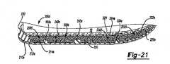
ソール構造200dは、層状構造に配置され、それらの間にキャビティ240dを画定するアウトソール210d及びミッドソール220dを含み得る。アウトソール210dは、接地面212dとはアウトソール210dの反対側に配置された内面214dを含む。アウトソール210dは、トウ領域1300、フォアフット領域1302、ミッドフット領域1304、及びヒール領域1306を形成するように、キャビティ240d内の外側面18と内側面20との間に延在する一連の溝442,444,446(図14及び図15)を画定し得る。いくつかの実施例では、アウトソール210dは、領域1300,1302,1304,1306の対応する領域内に位置する1つ以上の閉じた溝1400,1402,1404,1406をさらに画定する。閉じた溝とは、その両端で閉じられて、キャビティ240d内の内部領域を完全にまたは部分的に囲むループを形成する、1つ以上の側面が閉鎖された溝を意味する。対応する溝1400〜1406によって形成された内部領域は、多角形(例えば、長方形または台形)または楕円形のような同一または異なる形状を含み得る。図16は、対称的に配置された2つの閉じた溝1400を有するトウ領域1300を示し、フォアフット領域1302は閉じた溝1402を有し、ミッドフット領域1304は閉じた溝1404を有し、ヒール領域1306は閉じた溝1406を有する。各閉じた溝1400〜1406は、図17及び図18に示すように、ミッドソール220dに向かう方向にキャビティ240d内に延在し得るすることができる。 The
ミッドソール220dは、フットベッド224dとはミッドソール220cの反対側に配置された底面222dを含み、かつ、アウトソール210dと一体的に形成され得る。ソール構造200dは、アッパー100の内部ボイド102の少なくとも一部内のフットベッド224b上に配置されたインソール228をさらに含み得る。底面222dは、内面214dと対向してキャビティ240dを画定する。側壁230は、底面222dと内面214dとを分離してキャビティ240dの深さを画定し得、ミッドソール222dと同様に、アウトソール210dと一体的に形成され得る。 The
いくつかの実施例では、粒状物質350は、アウトソール210dの内面214d、ミッドソール220dの底面222d、及び、側壁230の間のキャビティ240d内に存在する。図12〜図15の例とは対照的に、粒状物質350を収容するために使用されるケーシングは存在しない。代わりに、粒状物質350により、キャビティ240dの容積の一部または全部が充填される。図17を参照すると、図16の線17−17に沿ったヒール領域1306の断面図は、閉じた溝1406とソール構造200dのキャビティ240d内に存在する粒状物質350とを示す。いくつかの例では、アウトソール210dは、ミッドソール220dに向かう方向にキャビティ240d内に曲がって先細り、閉じた溝1406を形成する。他の例では、アウトソール210dは、キャビティ240d内に先細になることなく曲がるか湾曲する。閉じた溝1406は、外側面18に近接して配置された仕切り368と、内側面20に近接して配置された仕切り370と、を画定する。外側周辺領域1718が、外側面18において仕切り368と側壁230との間に形成され、内側周辺領域1720が内側面において仕切り370と側壁230との間に形成され、内部領域1722が、仕切り368,370の間(例えば、内部領域1722は閉じた溝1406によって囲まれる)に形成される。粒状物質350は、領域1718、1720、1722のそれぞれにおいてキャビティ240d内に存在し得る。いくつかの実施例では、仕切り368,370は、アウトソール210dからキャビティ240d内に延在し、ミッドソール220dの底面222dに接触することなく終端する遠位端部を有する。すなわち、仕切り368,370の遠位端と底面222dとは、対応する間隙によって分離されている。仕切り368,370と底面222dとを分離する対応する間隙は、領域1718,1720,1722に存在する粒状物質350が、ソール構造200dの勾配荷重中に間隙を介して隣接する領域に移動することを可能にする。他の実施例では、仕切り368,370は、アウトソール210dからキャビティ240d内に延在し、ミッドソール220dの底面222dとの接点で終端する遠位端を有し、これにより、粒状物質350が、底面222dと接触する仕切り368,370によって分割されて離間された隣接する領域1718,1720,1722間を移動することを防止する。ミッドソール220dは、図1〜図3のミッドソール220を形成する柔軟性材料から形成され、ミッドソール220dに十分な柔軟性を付与し、これにより、ソール構造200dの勾配荷重中にキャビティ240d内に受容された粒状物質350が足の裏の形状と相互作用することを可能にする。 In some embodiments, the
図18を参照すると、図16の線18−18に沿ったフォアフット領域1302の部分断面図が、閉じた溝1402とソール構造200dのキャビティ240d内に存在する粒状物質350とを示す。いくつかの例では、アウトソール210dは、ミッドソール220dに向かう方向にキャビティ240d内に曲がって先細り、閉じた溝1402を形成する。他の例では、アウトソール210dは、キャビティ240dに先細りすることなく曲がるか湾曲する閉じた溝1402は、外側面18に近接して配置された仕切り468と、内側面20に近接して配置された仕切り470と、を画定する。外側周辺領域1818は、外側面18において仕切り468と側壁230との間に形成され、内側領域1820が、内側面20において仕切り470と側壁230との間に形成され、内部領域1822が、仕切り468,470の間(例えば、内部領域1822は閉じた溝1402の間に囲まれる)に形成される。 Referring to FIG. 18, a partial cross-sectional view of the
粒状物質350は、領域1818,1820,1822のそれぞれにおいてキャビティ240d内に存在し得る。いくつかの実施例では、仕切り468,470は、アウトソール210dからキャビティ240d内に延在し、ミッドソール220dの底面222dに接触することなく終端する遠位端を有する。すなわち、仕切り468,470の遠位端と底面222dとは、対応する隙間によって分離されている。仕切り468,470と底面222dとを分離する対応する間隙は、領域1818,1820,1822に存在する粒状物質350が、ソール構造200dの勾配荷重中に間隙を介して隣接する領域に移動することを可能にする。他の実施例では、仕切り468,470は、アウトソール210dからキャビティ240d内に延在し、ミッドソール220dの底面222dとの接点で終端する遠位端を有し、これにより、粒状物質350が、底面222dと接触する仕切り468,470によって分割されて離間された隣接する領域間を移動することを防止する。閉じた溝1400及び1404は、上記の実施例で説明した閉じた溝1402及び1406と同様に構成され得る。いくつかの構成では、ミッドソール220dまたはその一部を除去して、足の裏を支持するインソール228とキャビティ240dに存在する粒状物質350との間の直接的な接触をもたらし得る。これらの構成では、インソール228は、ソール構造200dの勾配荷重中にキャビティ240d内に存在する粒状物質350が足の裏に適合することを可能にする柔軟なシュトローベルに相当し得る。
図19〜図21を参照すると、フットウェア物品10eが提供され、これは、アッパー100と、アッパー100に取り付けられたソール構造200eと、を含む。図19は、フットウェア10eの底面斜視図を示す。フットウェア物品10eに対するフットウェア物品10に関連する構成要素の構造及び機能の実質的な類似性を考慮して、同様の符号が同様の構成要素を識別するために図面及び以下に使用され、文字拡張子を含む同様の符号は、変更された構成要素を識別するために使用される。 Referring to FIGS. 19-21,
ソール構造200eは、層状構造に配置され、それらの間にキャビティ240eを画定する、アウトソール210e及びミッドソール220eを含み得る。アウトソール210eは、接地面212eとはアウトソール210eの反対側に配置された内面214eを含む。ミッドソール220eは、フットベッド224eとはミッドソール220eの反対側に配置された底面222eを含む。ソール構造200eは、アッパー100の内部ボイド102の少なくとも一部内のフットベッド224e上に配置されたインソール228をさらに含み得る。底面222eは、内面214eと対向してキャビティ240eを画定し、側壁230は、底面222eと内面214eとを分離してキャビティ240eの深さを画定する。 The
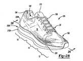
いくつかの実施例では、突起プレート300eがキャビティ240e内に延在して、フットウェア10eの使用中にキャビティ240eに存在する粒状物質350の移動を制限する。図20は、アウトソール210eの内面214eからミッドソール220eの底面222eに向かって矢印302の方向に延在する突起プレート300eを示すフットウェア物品10eの分解図を提供する。突起プレート300e、ミッドソール220e及びアウトソール210eは、ソール構造200eの周囲に延在し、足の輪郭に概ね対応する形状を有する。より具体的には、突起プレート300e、ミッドソール220e、及びアウトソール210eは、フォアフット部分12からヒール部分16まで、また、外側面18から内側面20まで延在する。開口部2000,2002,2004,2006は、突起プレート300eの面の間に延在し、アウトソール210eの内面214eの一部を露出させる開口部を形成する。突起プレート300eの面は、足の裏の形状に一致するよう輪郭を有し得る。開口部2000は、主にフォアフット部分12に配置され、別の開口部2002は、フォアフット部分12に配置されてミッドフット部分14に延在している。開口部2004は、ミッドフット部分14及びヒール部分16に配置され、開口部2006は、主としてヒール部分16に、足の踵骨に対応する位置に配置されている。すなわち、ヒール部分16の開口部2006は、概ね足の踵に対応するように配置される。 In some embodiments, the
開口部2000〜2006の各々は、対応する量の粒状物質350を受容して貯蔵するための、突起プレート300eの内壁によって囲まれた容器に相当する。突起プレート300eがアウトソール210eの内面214eからミッドソール220eの底面222eに向かって延在する距離は、開口部/容器2000〜2006の深さを画定する。いくつかの例では、突起プレート300eは、アウトソール210eの内面214eからキャビティ240e内に部分的に延在し、突起プレートの上(例えば、開口部2000〜2006の外側)に存在する粒状物質350がキャビティ240eを通ってソール構造200eの隣接する部分12,14,16に移動することを可能にする。他の例では、突起プレート300eは、キャビティ240eの中を内面214eからミッドソール220eの底面222eと接触するまで延在して開口部2000〜2006を閉鎖し、これにより、開口部2000〜2006内に存在する粒状物質350が移動したりシフトして離れることを防止すする。 Each of the openings 2000-2006 corresponds to a container enclosed by the inner wall of the
突起プレート300eは、例えば、ポリマーを含む多様な材料から形成され得る。好適なポリマーには、ポリエステル、熱硬化性ウレタン、熱可塑性ウレタン、種々のナイロン配合物、ゴム、ポリエーテルブロックアミド、ポリブチレンテレフタレート、またはこれらの材料の混合材が含まれる。また、複合材料が、ガラス繊維または炭素繊維を上記の種々のポリマー材料に組み込むことによって形成され得る。いくつかの例では、プレート300eは、ポリマー発泡体材料から形成され得る。したがって、ソール構造200eの所望の特性に応じて、様々な異なる材料を突起プレート300eの製造に利用し得る。ミッドソール220eは、図1〜図3のミッドソール220を形成する柔軟性材料から形成されてもよい。ミッドソール220eに十分な柔軟性を付与することにより、ミッドソール220eがアウトソール210eの内面214eに向かって並進するにつれ、ソール構造200eの勾配荷重中に、キャビティ240a内に存在する突起プレート300e及び粒状物質350が足の裏にクッションを提供すことを可能にする。 The
図21を参照すると、図19の線21−21に沿った断面図が、ミッドソール220eとアウトソール210eとの間のキャビティ240e内に存在する粒状物質350を示す。この例は、アウトソール210eの内面214eからキャビティ240e内に部分的に延在する突起プレート300eと、内面214eを露出させる突起プレート300eの面を貫通する開口部2000〜2006と、を示す。粒状物質350により、底面222dと内面214eまたは突起プレート300eとの間のキャビティ240eの容積の一部または全部が満たされ得る。突起プレート300eが内面214eから離れる方向に延在する距離は、開口部2000〜2006の深さを画定する突起プレート300eの内壁の高さに相当する。したがって、開口部2000〜2006の深さ内に存在する粒状物質350は、隣接する開口部に移動することが制限される。しかしながら、キャビティ240e内に占有されていない空間が存在する場合、開口部2000〜2006の深さより上に存在する粒状物質350は、隣接する開口部間を移動し得る。いくつかの構成では、ミッドソール220eまたはその一部を除去して、足の裏を支持するインソール228とキャビティ240eに存在する粒状物質350との間の直接的な接触をもたらし得る。これらの構成では、インソール228は、ソール構造200eの勾配荷重中にキャビティ240eに存在する粒状物質350が足の裏に適合することを可能にする柔軟なシュトローベルに相当し得る。 Referring to FIG. 21, a cross-sectional view along line 21-21 of FIG. 19 shows the
図22〜図24を参照すると、いくつかの実施例では、フットウェア物品10fは、アッパー100とアッパー100に取り付けられたソール構造200fとを含む。フットウェア物品10fに対するフットウェア物品10に関連する構成要素の構造及び機能の実質的な類似性を考慮して、同様の符号が同様の構成要素を識別するために図面及び以下に使用され、文字拡張子を含む同様の符号は、変更された構成要素を識別するために使用される。ソール構造200fは、層状構造に配置され、それらの間にキャビティ240fを画定するアウトソール210f及びミッドソール220fを含み得る。アウトソール210fは、接地面212とはアウトソール210fの反対側に配置される内面214fを含む。ミッドソール220fは、フットベッド224とはミッドソール220fの反対側に配置される底面222fを含む。底面222fは内面214fと対向してその間にキャビティ240fを画定する。側壁230は、底面222fと内面214fとを分離してキャビティ240fの深さを画定し得る。 Referring to FIGS. 22-24, in some embodiments, the
いくつかの実施例では、突起300fがキャビティ240f内に延在して足のクッションを提供すと共に、フットウェア10fの使用中にキャビティ240a内に存在する粒状物質350を含む房状ケーシング400の動作を支持し、かつ、制限する。突起300fは、図1〜図3の突起300を形成する1つ以上のポリマー発泡体材料から形成され、荷重がかかったときに弾力のある圧縮性をもたらして地面反力を減衰させる。図23は、アウトソール210fの内面214fからミッドソール220fの底面222fに向かう方向に延在する突起300fを示すフットウェア物品10fの分解図を提供する。この実施例では、粒状物質350(例えば、発泡ビーズ)を含む房状ケーシング400は、アウトソール210fの内面214fから延在する突起300f上に配置される。房状ケーシング400は、ミッドソール220f及びアウトソール210fの輪郭に略一致するようなサイズ及び形状にされ得る。いくつかの例では、突起300fは反復列に配置され、各突起300fは隣接する突起300fから等間隔に離間される。他の例では、突起300fは交互に互い違いに反復列に配置されている。ミッドソール220fは、図1〜図3のミッドソール220を形成する柔軟性材料から形成て十分な柔軟性を有するミッドソール220fを提供し、これにより、ソール構造200fの勾配荷重中に、房状ケーシング400内に受容され、キャビティ240f内に存在する粒状物質350が足の裏の形状と相互作用することを可能にする。 In some embodiments, the
房状ケーシング400は、柔軟性材料から形成され得る。1つの構成では、房状ケーシング400は、メッシュ材料から形成される。これに加えてまたはこれに代えて、房状ケーシング400は、ナイロン材料から形成されてもよい。したがって、房状ケーシング400は、柔軟性材料、メッシュ材料、及び/または、ナイロン材料から形成され得る。随意的に、房状ケーシング400は、受容された粒状物質350が、内面214f及び底面222fの表面形状それぞれに、ならびに、側壁230の輪郭など、ソール構造200fに適合することを可能にする任意の適切な材料から形成され得る。いくつかの構成では、ミッドソール220fまたはその一部を除去して、足の裏と粒状物質350を含む房状ケーシング400との間の直接的な接触をもたらし得る。 The
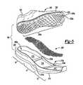
ケーシング400が突起300f上のキャビティ240fに受容された際に、房状ケーシング400の第1の端部402はヒール部分16に近接して位置し、房状ケーシング400の第2の端部404はフォアフット部分12に近接して位置する。房状ケーシング400は、材料の一部を互いにタフティング、接合、または締結することによって形成されて、それぞれが対応する量の粒状物質350で満たされる房状領域またはポケット440を画定し得る。第1の端部402及び第2の端部404、ならびに、ソール構造200fの外側面18と内側面20との間に配置される。いくつかの例では、各ポケット440は、略同じ量の粒状物質350を含み、他の例では、ポケット440の少なくとも1つは、異なる量の粒状物質350を含む。例えば、ヒール部分16に近接して位置するポケット440内により多くの粒状物質350を含み、足の踵領域におけるソフトタイプのクッションレベルを高めることが望ましいことがある。ポケット440は、対応する量の粒状物質350が隣接するポケットに移動するのを制限し得る。しかしながら、粒状物質350のある程度の動作は、対応するポケット440内で許容されて、ソール構造200fの勾配荷重中に流体クッションを提供し得る。言い換えれば、ポケット440は、ソール構造200fの繰り返される圧縮中の粒状物質の移動によって生じる、ソール構造200fの領域におけるクッションの損失を防止するのに有効であるが、各ポケット440内の粒状物質350の動作は可能にする。 When the
図24を参照すると、図22の線24−24に沿った断面図は、キャビティ240f内、かつ、内面214fから延在する突起300fの上に受容された粒状物質350を含む房状ケーシング400を示す。図24は、房状ケーシング400を支持する突起300fと、ソール構造200fに荷重がかかっていないとき(すなわち、ソール構造200fが静止しているとき)に、ミッドソール220fから離間している突起300fと、を示す。しかしながら、ソール構造200fを圧縮すると、ミッドソール220fの底面222fは、粒状物質350を含む房状ケーシング400と協働して、アウトソール210fに向かって並進し、1つ以上の突起300fと接触し得る。ここで、突起300fは、ソール構造200fの勾配荷重中に房状ケーシング400のポケット440内に配置された粒状物質350が圧縮するにつれ、底面222fと接触しながら圧縮され得る。上述したように、粒状物質350による圧縮性はソフトタイプのクッションを提供し、一方、突起300fによる圧縮性は応答タイプのクッションを提供し得る。したがって、房状ケーシング400内に存在する突起300f及び粒状物質350は、かかる荷重が変化するにつれて変化する勾配クッションをフットウェア物品10fにもたらすように協働し得る(すなわち、荷重が大きくなるほど、突起300fが圧縮され、したがって、フットウェア10fがより高い応答性を発揮する)。いくつかの構成では、ミッドソール220fまたはその一部を除去して、足の裏と、房状ケーシング400のポケット440内に配置され、キャビティ240fに存在する粒状物質350とのより密接な接触をもたらし得る。これらの構成では、足の裏に対向するケーシング400の面は、ソール構造200fの勾配荷重中にポケット440に存在する粒状物質350が足の裏に適合することを可能にする柔軟なシュトローベルに相当し得る。 Referring to FIG. 24, a cross-sectional view taken along line 24-24 of FIG. 22 comprises a
図25〜図27を参照すると、フットウェア物品10gが提供され、これはアッパー100と、アッパー100に取り付けられたソール構造200gと、を含む。フットウェア物品10gに対するフットウェア物品10に関連する構成要素の構造及び機能の実質的な類似性を考慮して、同様の符号が同様の構成要素を識別するために図面及び以下に使用され、文字拡張子を含む同様の符号は、変更された構成要素を識別するために使用される。ソール構造200gは、層状構造に配置され、それらの間にキャビティ240gを画定するアウトソール210g及びミッドソール220gを含む。アウトソール210gは、接地面212とはアウトソール210gの反対側に配置された内面214gを含む。ミッドソール220gは、フットベッド224とはミッドソール220gの反対側に配置される底面222gを含む。底面222gは内面214gに対向してこれらの間にキャビティ240gを画定する。側壁230は、底面222gと内面214gとを分離してキャビティ240gの深さを画定し得る。 Referring to FIGS. 25-27, 10 g of footwear article is provided, which includes an upper 100 and a
突起300gは、キャビティ240g内に延在して足にクッションを提供し、同時に、フットウェア10fの使用中にクッション層500とキャビティ240gに存在する粒状物質350を含む房状ケーシング400とを支持する。突起300gは、荷重がかかったときに弾力のある圧縮性をもたらして地面反力を減衰させる、図1〜図3の突起300を形成する1つ以上のポリマー発泡体材料から形成され得る。図26は、房状ケーシング400、クッション層500、及び、アウトソール210gの内面214gからミッドソール220gの底面222gに向かう方向に延在する突起300gを示すフットウェア物品10gの分解図を提供する。房状ケーシング400及びクッション層500はそれぞれ、フォアフット部分12、ミッドフット部分14、及び、ヒール部分16を通ってそれぞれ貫延在する長さと、外側面18及び内側面20の間の幅と、をそれぞれ有し得る。房状ケーシング400及びクッション層500は、ミッドソール220g及びアウトソール210gの輪郭に略一致するようなサイズ及び形状にすることができる。ソール構造200gが組み立てられ際、クッション層500は、突起300gの遠位端と房状ケーシング400との間に置かれ、これらと接触し得る。クッション層500は、クッション層500の面に沿って配置された複数のリッジ510を形成していわゆるエッグクラッド形状を画定する輪郭構造を含み得る。クッション層500は、エチルビニルアセテートまたはポリウレタンのような1つまたは複数のポリマー発泡体材料から形成され得る。各突起300gは、アウトソール210gに対向するクッション層500の対応するリッジ510と位置合わせされ得る。ミッドソール220gは、十分な柔軟性を有する、図1から図3のミッドソール220を形成する柔軟性材料から形成され、これにより、ソール構造200gの勾配荷重中に、房状ケーシング400内に受容され、キャビティ240g内に存在する粒状物質350が足の裏の形状と相互作用することを可能にする。 The
図27を参照すると、図25の線27−27に沿った断面図が、粒状物質350を含む房状ケーシング400と、アウトソール210gの内面214gから延在する突起300g上のキャビティ240g内に受容されたクッション層500と、を示す。図27は、アウトソール210gに対向しており、内面214gからキャビティ240g内に延在する突起300gによって支持されているクッション層500の各リッジ510を示す。一対のリッジ510とキャビティ240g内に位置する突起300gとは協働して、荷重がかかったときに弾力のある圧縮性をもたらして接地反力を減衰させ得る。例えば、リッジ510と突起300gとの対は、荷重がかかったときに互いに圧縮して、足にかかる衝撃の大きさを減衰させるばね効果をもたらし得る。いくつかの例では、リッジ510と突起300gとの対の間のボイドには、粒状物質350が充填され得る。リッジ510と突起300gとの対によってもたらされる弾力のある圧縮性に加えて、ケーシング400は、ソール構造200gの勾配荷重中に圧縮する。上述のように、粒状物質350による圧縮性はソフトタイプのクッションを提供し、一方、突起300gによる圧縮性は応答タイプのクッションをもたらし得る。したがって、突起300g、クッション層500、及び、房状ケーシング400内に存在する粒状物質350は協働して、かかる荷重が変化するにつれて変化する勾配クッションをフットウェア10gへのもたらし得る(すなわち、荷重が大きくなるにつれ、より多くの突起300gが圧縮され、したがって、フットウェア10gがより高い応答性を発揮する)。いくつかの構成では、ミッドソール220gまたはその一部を除去して、足の裏と粒状物質350を含む房状ケーシング400との間の直接的な接触をもたらし得る。 Referring to FIG. 27, a cross-sectional view along line 27-27 of FIG. 25 is received in the
図28及び図29を参照すると、いくつかの実施例では、フットウェア物品10hは、アッパー100及びアッパー100に取り付けられたソール構造200hを含む。フットウェア物品10hに対するフットウェア物品10に関連する構成要素の構造及び機能の実質的な類似性を考慮して、同様の符号が同様の構成要素を識別するために図面及び以下に使用され、文字拡張子を含む同様の符号は、変更された構成要素を識別するために使用される。ソール構造200hは、層状構造に配置され、それらの間にキャビティ240hを画定するアウトソール210h及びミッドソール220hを含み得る。アウトソール210hは、接地面212とはアウトソール210hの反対側に配置される内面214hを含む。ミッドソール220hは、フットベッド224とはミッドソール220hの反対側に配置される底面222hを含む。底面222hは内面214hと対向してそれらの間にキャビティ240hを画定する。側壁230は、底面222hと内面214hとを分離してキャビティ240hの深さを画定し得る。 Referring to FIGS. 28 and 29, in some embodiments, the
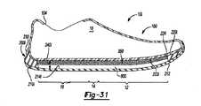
いくつかの実施例では、ソール構造200hは、クッション層500hと、キャビティ240h内に配置された粒状物質350と、を含む。図29を参照すると、図28の線29−29に沿った断面図が、アウトソール210hの内面214hに配置されたクッション層500hと、ソール構造200hに荷重がかかっていない際(すなわち、ソール構造200hが静止している際)にクッション層500hとミッドソール220hの底面222hとの間に配置された所定量の粒状物質350と、を示す。いくつかの実施例では、クッション層500hは、キャビティ240h内の空きスペースの一部を占めるような大きさと形状のポリマー発泡体のスラブを含む。ここで、クッション層500hと底面222hとの間の隙間は、粒状物質350を受容するキャビティ240h内の空きスペースの残りの部分を画定する。いくつかの例では、粒状物質350(例えば、泡状ビーズ)が、側壁230、ミッドソール220hの底面222h、及び、クッション層500hに囲まれた領域(粒状物質350の個々のビーズの間のボイド以外)を略占めることを可能にするように、キャビティ240h内の空きスペースの残りの部分をわずかに超えて充填される(例えば詰め込まれる)。ミッドソール220hは、図1〜図3のミッドソール220を形成する柔軟性材料から形成され得、十分な柔軟性を有するミッドソール220hを提供し、これによって、ソール構造200hの勾配荷重中に、キャビティ240h内に受容された粒状物質350が足の裏の形状と相互作用することを可能にする。 In some embodiments, the
ソール構造200hの勾配荷重中に、ミッドソール220hは、ミッドソール220hとクッション層500hとの間で粒状物質350が圧縮するにつれ、アウトソール210hに向かって並進し得る。ここで、クッション層500hは、アウトソール210hとミッドソール220hとの間で弾力的に圧縮する。クッション層500hは、クッション層500h上に存在する所定量の粒状物質350(例えば、発泡ビーズ)と共に、機能性を高め、従来ミッドソールが提供するクッション性を高めるように協働し得る。例えば、ソール構造200hに荷重がかかっている際に、粒状物質350の圧縮は、地面反力の初期衝撃時にソフトタイプのクッションレベルをもたらし、クッション層500hの圧縮は初期衝撃の後に起こり、応答タイプのクッションを提供し得る。したがって、キャビティ240h内に存在する粒状物質350及びクッション層500hは協働して、かかる荷重が変化するにつれて変化する勾配クッションをフットウェア物品10hにもたらし得る(すなわち、荷重が大きいほどクッション層500hは圧縮し、したがって、フットウェア10hがより高い応答性を発揮する)。 During the gradient load of the
図30及び図31を参照すると、いくつかの実施例において、フットウェア物品10iは、アッパー100とアッパー100に取り付けられたソール構造200iとを含む。フットウェア物品10iに対するフットウェア物品10に関連する構成要素の構造及び機能の実質的な類似性を考慮して、同様の符号が同様の構成要素を識別するために図面及び以下に使用され、文字拡張子を含む同様の符号は、変更された構成要素を識別するために使用される。ソール構造200iは、層状構造に配置され、それらの間にキャビティ240iを画定するアウトソール210i及びミッドソール220iを含み得る。アウトソール210iは、接地面212とはアウトソール210iの反対側に配置される内面214iを含む。ミッドソール220iは、フットベッド224とはミッドソール220iの反対側に配置される底面222iを含む。底面222iは内面214iと対向してそれら間にキャビティ240iを画定する。側壁230は、底面222iと内面214iとを分離してキャビティ240iの深さを画定し得る。 Referring to FIGS. 30 and 31, in some embodiments, the footwear article 10i includes an upper 100 and a sole structure 200i attached to the upper 100. Given the substantial similarity in structure and function of the components associated with the footwear article 10i to the footwear article 10i, similar reference numerals are used in the drawings and below to identify similar components and letters. Similar codes, including extensions, are used to identify modified components. The sole structure 200i may include an outsole 210i and a midsole 220i that are arranged in a layered structure and define a cavity 240i between them. The outsole 210i includes an inner surface 214i located on the opposite side of the outsole 210i from the
いくつかの実施例では、ソール構造200iは、流体充填チャンバ600と、キャビティ240i内に配置された粒状物質350と、を含む。いくつかの例では、流体充填チャンバ600は、加圧流体を受容し、その中に加圧流体を保持するための耐久性のある密封バリアを形成する内部ボイドを画定する。加圧流体は空気であり得る。流体充填チャンバ600を形成するために、広範囲のポリマー材料を利用し得る。ポリマー材料の選択において、引張強度、伸長特性、疲労特性、及び動的弾性率などの工学的特性、ならびに、チャンバ600に収容された流体の拡散を防止する材料の機能が考慮される。流体充填チャンバ600を形成するために使用される例示的な材料は、熱可塑性ウレタン、ポリウレタン、ポリエステル、ポリエステルポリウレタン、及びポリエーテルポリウレタンのうちの1つ以上を含み得る。 In some embodiments, the sole structure 200i comprises a
図31を参照すると、図30の線31−31に沿った断面図は、アウトソール210iの内面214i上に配置された流体充填チャンバ600と、ソール構造200iに荷重がかかっていない際(すなわち、ソール構造200iが静止している際)に流体充填チャンバ600とミッドソール220iの底面222iとの間に配置された所定量の粒状物質350を示すに加えられる。いくつかの例では、流体充填チャンバ600は、キャビティ240i内の空きスペースの一部を占めるような大きさ及び形状にされる。ここで、流体充填チャンバ600と底面222iとの間の隙間は、粒状物質350を受容するキャビティ240i内の空きスペースの残りの部分を画定する。いくつかの例では、粒状物質350(例えば、泡状ビーズ)が、キャビティ240i内の空きスペースの残りの部分をわずかに超えて占めて(例えば、詰め込まれて)、粒状物質350が、側壁230、ミッドソール220iの底面222i、及び、流体充填チャンバ600に囲まれた領域(粒状物質350の個々のビーズ間のボイドを除く)を略占めることを可能にする。ミッドソール220iは、図1〜図3のミッドソール220を形成する柔軟性材料から形成されて、十分な柔軟性を有するミッドソール220iを提供し、これにより、ソール構造200iの勾配荷重中に、キャビティ240i内に受容された粒状物質350が足の裏の形状と相互作用することを可能にする。 Referring to FIG. 31, the cross-sectional view along line 31-31 of FIG. 30 shows the
ソール構造200iの勾配荷重中に、ミッドソール220iは、粒状物質350がミッドソール220iと流体充填チャンバ600との間で圧縮するにつれて、アウトソール210iに向かって並進し得る。ここで、流体充填チャンバ600内の流体がアウトソール210hとミッドソール220hとの間で圧縮し、流体充填チャンバ600上に存在する所定量の粒状物質350(例えば、発泡ビーズ)と共に、従来のミッドソールが提供する機能性及びクッション性を高めるために協働し得る。例えば、ソール構造200iに荷重がかかる際に、粒状物質350の圧縮は、地面反力の中にソフトタイプのクッションレベルをもたらし、初期衝撃後に起こり得る、流体充填チャンバ600に含まれる流体の圧縮は、応答タイプのクッションを提供す。したがって、キャビティ240i内に存在する粒状物質350及び流体充填チャンバ600は協働して、かかる荷重が変化するにつれて変化する勾配クッションをフットウェア物品10iにもたらし得る(すなわち、荷重が大きいほど、流体充填チャンバ600内の流体がより圧縮し、したがって、フットウェア10iがより高い反応性を発揮する)。 During the gradient load of the sole structure 200i, the midsole 220i may translate towards the outsole 210i as the
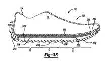
図32及び図33を参照すると、フットウェア物品10jが提供され、これはアッパー100及びアッパー100に取り付けられたソール構造200jを含む。フットウェア物品10jに対するフットウェア物品10に関連する構成要素の構造及び機能の実質的な類似性を考慮して、同様の符号が同様の構成要素を識別するために図面及び以下に使用され、文字拡張子を含む同様の符号は、変更された構成要素を識別するために使用される。With reference to FIGS. 32 and 33,
ソール構造200jは、層状構造に配置され、それらの間にキャビティ240iを画定する、図30及び図31のアウトソール210j及びミッドソール220iを含み得る。ソール構造200jはまた、流体充填チャンバ600と、キャビティ240i内に配置された粒状物質350と、を含む。他の実施例では、流体充填チャンバ600の代わりに、図28及び図29の底部クッション部材500hが内面214i上に配置され得る。 The sole structure 200j may include the
図33を参照すると、図32の線33−33に沿った断面図が、アウトソール210jの内面214i上に配置された流体充填チャンバ600と、ソール構造200jに荷重がかかっていない際(すなわち、ソール構造200jが静止している際)に流体充填チャンバ600とミッドソール220iの底面222iとの間に配置された所定量の粒状物質350と、を示す。図30及び図31のアウトソール210iが略平坦な接地面212を含むことを示す一方で、図33は、キャビティ240iから離れるように延在し、地面と接触する一連のボトムリッジまたは突起213jを画定する接地面212jを含む、フットウェア物品10jのアウトソール210jを示す。ここで、接地面212jは、フットウェア10jの使用中に地面と係合のするためにソール構造200jが転動する際に、アウトソール210jが曲げられ撓むことを可能にする。 Referring to FIG. 33, a cross-sectional view taken along line 33-33 of FIG. 32 shows the
突起213jは、荷重がかかったときにミッドソール220iに向かって移動し、粒状物質350をミッドソール220iに向けて付勢するので、フットウェア物品10jの使用中にいわゆるピストンとして作用し得る。ミッドソール220iは、フットウェア物品10iに関して上述したように、柔軟性材料から形成されるので、突起213j及び粒状物質350のこのような上方への移動は、ユーザの足の裏で感じられ、ユーザに使用中に顕著で応答性の高いクッション性をもたらす。このようなクッション性は、アウトソール210jに沿った所定の位置に突起213jを位置決めすることによって、及び/または、突起213jの相対的なサイズを調整することによって調整され得る。例えば、ヒール部分16は、フォアフット部分12よりも大きな突起213j、及び/または、突起213jのより大きな密度を含むことで、踵への衝撃が起こっている間により多くの粒状物質350の上方への動きをもたらし得る。 The protrusion 213j moves toward the midsole 220i when a load is applied and urges the
図34及び図35を参照すると、フットウェア物品10kが提供され、これはアッパー100とアッパー100に取り付けられたソール構造200kとを含む。フットウェア物品10kに対するフットウェア物品10に関連する構成要素の構造及び機能の実質的な類似性を考慮して、同様の符号が同様の構成要素を識別するために図面及び以下に使用され、文字拡張子を含む同様の符号は、変更された構成要素を識別するために使用される。 Referring to FIGS. 34 and 35, a
ソール構造200kは、層状構造に配置され、それらの間にキャビティ240kを画定する、アウトソール210kと図22〜図23のミッドソール220fとを含み得る。図35を参照すると、図34の線35−35に沿った部分断面図が、キャビティ240kから離れて延在する一連のボトムリッジまたは突起213kを画定する接地面212kと、接地面212kとはアウトソール210kの反対側に配置され、キャビティ240k内に延在する一連のアッパーリッジまたは突起215kを画定する内面214kと、を含むものとしてアウトソール210kを示している。 The
ボトムリッジ213kは、図32及び図33のボトムリッジ213jと略同一であり、したがって、延在して地面と接触して、フットウェア10kの使用中にソール構造200kが地面との係合のために転動すると、アウトソール210kが曲がって撓むことを可能にする。アッパーリッジ215kはキャビティ240k内に延在し、フットウェア10kの使用中にキャビティ240k内に存在する粒状物質350を含む房状ケーシング400の動きを支持し、かつ、制限する。さらに、アッパーリッジ215kは、ボトムリッジ213kに加えられる荷重が対応するアッパーリッジ215kに直接的に伝達されるように、ボトムリッジ213kのそれぞれと位置決めされ、これにより、アウトソール210kと房状ケーシング400との間に荷重経路を形成し得る。 The
房状ケーシング400は、図22〜図24を参照して上述されており、ケーシング400が、アウトソール210kの内面214kによって画定されるアッパーリッジ215k上のキャビティ240kによって受容された際に、ヒール部分16に近接する第1の端部402と、フォアフット部分12に近接する第2の端部404と、を含む。ケーシング400は、等しい量または異なる量の粒状物質350を含むポケット440を含み得る。図22〜図24のアウトソール210fが、内面214fからキャビティ240f内に延在する突起300fを含む一方で、図35は、フットウェア10kの使用中に足のための応答タイプのクッションを提供すために粒状物質350を含有するケーシング400を支持するように、突起300fの代わりにキャビティ240k内に延在する内面214kのアッパーリッジ215kを示す。応答タイプのクッションは、ミッドソール220fと房状ケーシング400とが協働して使用中にアッパーリッジ215kでアウトソール210kに荷重を加える際に、アッパーリッジ215kから各ボトムリッジ213kへの直接的な荷重経路を形成ることによってさらに高められる。 The
図35は、ソール構造200kに荷重がかかっていない際(すなわち、ソール構造200kが静止している際)に、房状ケーシング400を支持し、ミッドソール220fから離間しているアッパーリッジ215kを示す。しかしながら、ソール構造200kを圧縮すると、ミッドソール220fの底面222fは、粒状物質350を含む房状ケーシング400と協働して、アウトソール210kに向かって並進し、内面214kによって画定された1つ以上のアッパーリッジ215kと接触する。ここで、アッパーリッジ215kは、ソール構造200kの勾配荷重中に、房状ケーシング400のポケット440内に位置する粒状物質350が圧縮して動くにつれ、底面222fと接触しながら圧縮し得る。 FIG. 35 shows the upper ridge 215k that supports the
アウトソール210kは、弾性タイプの材料で形成され、アッパーリッジ215kが図22〜図24の突起300fと同じように圧縮する際に、応答タイプのクッションを提供し得る。上述のように、粒状物質350による圧縮性は、ソフトタイプのクッションを提供す。したがって、アッパーリッジ215kと房状ケーシング400内に存在する粒状物質350とは、かかる荷重が変化するにつれて変化する勾配クッションをフットウェア10kにもたらすように協働し得る(すなわち、荷重が大きいほど、アッパーリッジ215kはより圧縮され、したがって、フットウェア10kがより高い応答性を発揮する)。上述したように、ミッドソール220fは、図1〜図3のミッドソール220を形成する柔軟性材料から形成され、ミッドソール220fに十分な柔軟性をもたあし、これにより、ソール構造200kの勾配荷重中に、房状ケーシング400内に受容され、キャビティ240kに存在する粒状物質350が足の裏の形状と相互作用することを可能にする。いくつかの構成では、ミッドソール220fまたはその一部を除去して、足の裏と粒状物質350を含む房状ケーシング400との間の直接的な接触をもたらし得る。 The
図36及び図37を参照すると、フットウェア物品10lが提供され、これは、アッパー100とアッパー100に取り付けられたソール構造200lとを含む。フットウェア物品10lに対するフットウェア物品10に関連する構成要素の構造及び機能の実質的な類似性を考慮して、同様の符号が同様の構成要素を識別するために図面及び以下に使用され、文字拡張子を含む同様の符号は、変更された構成要素を識別するために使用される。ソール構造200lは、層状構造に配置され、それらの間にキャビティ240lを画定する、図25〜図27のアウトソール210l及びミッドソール220gを含み得る。。 Referring to FIGS. 36 and 37, 10 liters of footwear article is provided, which includes an upper 100 and a
図37を参照すると、図36の線37−37に沿った部分断面図が、アウトソール210lが、キャビティ240lから離れるように延在する一連のボトムリッジ213lを画定する接地面212lと、接地面212lとはアウトソール210lの反対側に配置され、キャビティ240l内に延在する一連のアッパーリッジ215lを含む。ボトムリッジ213lは、図32及び図33のボトムリッジ213jと略同一であり、したがって、延在して地面と接触し、フットウェア10lの使用中に底面との係合のためにソール構造200lが転動すると、アウトソール210lが曲がって撓むことを可能にする。 Referring to FIG. 37, a partial cross-sectional view along line 37-37 of FIG. 36 shows a ground plane 212l defining a series of bottom ridges 213l in which the outsole 210l extends away from the cavity 240l. The 212l is located on the opposite side of the 210l outsole and contains a series of upper ridges 215l extending within the 240l cavity. The bottom ridge 213l is substantially identical to the bottom ridge 213j of FIGS. 32 and 33, thus extending and contacting the ground and having a sole structure 200l for engagement with the bottom surface during use of the footwear 10l. When rolled, the outsole 210l allows it to bend and bend.
アッパーリッジ215lは、キャビティ240l内に延在して足にクッションを提供すると共に、フットウェア10lの使用中に、クッション層500lとキャビティ240lに存在する粒状物質350を含む房状ケーシング400とを支持する。房状ケーシング400及びクッション層500lは、ミッドソール220g及びアウトソール210lの周囲に略一致するようなサイズ及び形状にされ得る。ソール構造200lが組み立てられる際、クッション層500lは、アウトソール210lの内面214lのアッパーリッジ515lの遠位端と房状ケーシング400との間に置かれ、かつ、これらと接触し得る。 The upper ridge 215l extends into the cavity 240l to provide cushioning to the foot and supports the cushioning layer 500l and the
クッション層500lは、いわゆる卵形の形状を画定するように、クッション層500lの両面に沿って配置された複数のボトムリッジ510l及びアッパーリッジ515lを形成する輪郭構造を含み得る。1つの構成では、ボトムリッジ510l及びアッパーリッジ515lは、アウトソール210lのボトムリッジ213l及びアッパーリッジ215lのそれぞれと位置決めされて、使用中に房状ケーシング400から地面への直接的な荷重経路を形成する。クッション層500lは、エチル−ビニルアセテートまたはポリウレタンのような1つまたは複数のポリマー発泡体材料から形成され得る。アウトソール210lの各アッパーリッジ215lは、アウトソール210lに対向するクッション層500の対応するボトムリッジ510lと位置合わせされ得る。クッション層500lの各アッパーリッジ515lは、房状ケーシング400の対応するポケット440に対向し、かつ、接触し得る。上述したように、ミッドソール220gは、図1〜図3のミッドソール220を形成する柔軟性材料から形成されて、十分な柔軟性を有するミッドソール220gを提供し、これにより、ソール構造200lの勾配荷重中に、房状ケーシング400内に受容され、キャビティ240l内に存在する粒状物質350が足の裏の形状と相互作用することを可能にする。 The cushion layer 500l may include a contour structure forming a plurality of bottom ridges 510l and upper ridges 515l arranged along both sides of the cushion layer 500l so as to define a so-called oval shape. In one configuration, the bottom ridge 510l and upper ridge 515l are positioned with each of the bottom ridge 213l and upper ridge 215l of the outsole 210l to form a direct load path from the
図37は、アウトソール210lに対向し、キャビティ240l内に延在する内面214lの対応するアッパーリッジ215lによって支持されているクッション層500lの各ボトムリッジ510lを示す。キャビティ240l内に位置するボトムリッジ510lとアッパーリッジ215lの対応する対は協働して荷重がかかったときに弾力のある圧縮性をもたらし、地面反力を減衰させ得る。例えば、ボトムリッジ510lとアッパーリッジ215lとの対は、荷重下で互いに圧縮して、足への衝撃の大きさを減衰させるばね効果をもたらし得る。いくつかの例では、ボトムリッジ510lとアッパーリッジ215lとの間のボイドは粒状物質350で満たされ得る。ボトムリッジ510lとアッパーリッジ215lとの対によって実現される弾力のある圧縮性に加えて、房状ケーシング400のポケット440が、ソール構造200lの勾配荷重中に圧縮し動く。上述したように、粒状物質350による圧縮性はソフトタイプのクッションを提供し、ボトムリッジ510l及びアッパーリッジ215lによる圧縮性は、応答タイプのクッションを提供し得る。したがって、アウトソール210l、クッション層500l、及び、房状ケーシング400内に存在する粒状物質350は協働して、かかる荷重が変化するにつれて変化する勾配クッションをフットウェア物品10lにもたらし得る(すなわち、荷重が大きいほど、リッジ310l、315l、510l、515lが圧縮され、従って、フットウェア10lがより高い応答性を発揮する)。いくつかの構成では、ミッドソール220gまたはその一部を除去して、足の裏と粒状物質350を含む房状ケーシング400との間の直接的な接触をもたらし得る。 FIG. 37 shows each bottom ridge 510l of the cushion layer 500l facing the outsole 210l and supported by the corresponding upper ridge 215l of the inner surface 214l extending into the cavity 240l. Corresponding pairs of bottom ridges 510l and upper ridges 215l located within the cavity 240l can work together to provide elastic compressibility and dampen ground reaction forces when loaded. For example, a pair of bottom ridge 510l and upper ridge 215l may provide a spring effect that compresses against each other under load to dampen the magnitude of the impact on the foot. In some examples, the void between 510 l of bottom ridge and 215 l of upper ridge may be filled with 350 of particulate matter. In addition to the elastic compressibility realized by the pair of bottom ridge 510l and upper ridge 215l, the
以下の条項は、上記のフットウェア物品のためのソール構造の例示的な構成を提供する。 The following provisions provide an exemplary configuration of the sole structure for the footwear article described above.
第1項:フットウェア物品は、アッパーとアッパーに取り付けられたアウトソールとを備え、接地面と、接地面とはアウトソールの反対側に配置される内面と、を有している。ミッドソールは、フットベッドと、フットベッドとはミッドソールの反対側に配置された底面とを有しており、底面は、アウトソールの内面に対向してその間にキャビティを画定しており、第1の一連の突起は、内面及び底面の一方から内面及び底面の他方に向かって第1の方向においてキャビティ内に延在している。第1の一連の突起は、内面及び底面の他方から離間している。第2の一連の突起は、第1の方向の内面及び底面の一方から内面及び底面の他方に向かってキャビティ内に延在し、第2の一連の突起は第1の一連の突起とは異なる高さを有しており、内面及び底面の他方から離間して配置されている。所定量の粒状物質はキャビティ内に配置される。Item 1: The footwear article comprises an upper and an outsole attached to the upper, and has a ground plane and an inner surface that is located on the opposite side of the ground plane from the ground plane. The midsole has a footbed and a bottom that is located on the opposite side of the midsole from the footbed, the bottom facing the inner surface of the outsole and defining a cavity between them. The series of protrusions of 1 extends into the cavity in a first direction from one of the inner surface and the bottom surface toward the other of the inner surface and the bottom surface. The first series of protrusions is separated from the other of the inner surface and the bottom surface. The second series of protrusions extends into the cavity from one of the inner and bottom surfaces in the first direction toward the other of the inner and bottom surfaces, and the second series of protrusions is different from the first series of protrusions. It has a height and is arranged away from the other of the inner surface and the bottom surface. A predetermined amount of particulate matter is placed in the cavity.
第2項:内面及び底面の一方は内面であり、所定量の粒状物質は、第1の一連の突起の基部の周り及び第2の一連の突起の基部の周りに配置されている、第1項のフットウェア物品。Item 2: One of the inner surface and the bottom surface is the inner surface, and a predetermined amount of particulate matter is arranged around the base of the first series of protrusions and around the base of the second series of protrusions. Item footwear goods.
第3項:第1の一連の突起は、第1の方向において減少する断面積を含む、前記項のいずれかのフットウェア物品。Item 3: The footwear article of any of the above items, wherein the first series of protrusions comprises a reduced cross-sectional area in the first direction.
第4項:第2の一連の突起は、第1の方向において減少する断面積を含む、前記項のいずれかのフットウェア物品。Item 4: The footwear article of any of the above items, wherein the second series of protrusions comprises a reduced cross-sectional area in the first direction.
第5項:第1の一連の突起及び第2の一連の突起は、継続的に先細の外面を含む、前記項のいずれかのフットウェア物品。Item 5. The footwear article of any of the above items, wherein the first series of protrusions and the second series of protrusions continuously include a tapered outer surface.
第6項:先細の外面は、内面及び底面の他方に対向する各突起の丸みを帯びた遠位端で終端する、第5項のフットウェア物品。Item 6: The footwear article of Item 5, wherein the tapered outer surface terminates at the rounded distal end of each protrusion facing the other side of the inner surface and the bottom surface.
第7項:第1の一連の突起は、アウトソールのヒール部分に近接して配置され、第2の一連の突起は、アウトソールのフォアフット部分に近接して配置される、前記項のいずれかのフットウェア物品。Item 7. Any of the above-mentioned items, wherein the first series of protrusions is placed close to the heel portion of the outsole and the second series of protrusions is placed close to the forefoot portion of the outsole. Footwear goods.
第8項:第1の一連の突起は、第2の一連の突起よりも内面及び底面の一方から遠くに延在する、第6項のフットウェア物品。Item 8. The footwear article of
第9項:粒状物質は、発泡ビーズを含む、前記項のいずれかのフットウェア物品。Item 9. The footwear article according to any one of the above items, wherein the particulate matter comprises foamed beads.
第10項:発泡ビーズは、実質的に球形を含む、第9項のフットウェア物品。
第11条:発泡ビーズは、おおよそ同じサイズ及び形状を含む、第9項のフットウェア物品。Article 11: Foam beads are footwear articles of paragraph 9, which include approximately the same size and shape.
第12項:発泡ビーズは、異なるサイズ及び形状の少なくとも1つを含む、第9項のフットウェア物品。
第13項:第1の一連の突起及び第2の一連の突起は、アウトソールのミッドフット部分に近接して配置されたボイドによって互いに離間されている、前記項のいずれかのフットウェア物品。Item 13. The footwear article of any of the above items, wherein the first series of protrusions and the second series of protrusions are separated from each other by voids placed close to the midfoot portion of the outsole.
第14項:フットウェア物品は、アッパーとアッパーに取り付けられたアウトソールとを備え、アウトソールは、接地面と、アウターソールの反対側に配置された内面とを備えている。内面は、アッパーに向かう方向に延在する第1の一連の突起と、アッパーに向かって延在し、第1の一連の突起とは異なる高さを有する第2の一連の突起と、を含む。ミッドソールは、フットベッドと、フットベッドとはミッドソールの反対側に配置され、アウトソールの内面に対向してその間にキャビティを画定する底面とを有し、底面は、第1の一連の突起及び第2の一連の突起から離間されている。所定量の粒状物質はキャビティ内に配置される。
第15項:第1一連の突起は、アウトソールからミッドソールに向かって延在する方向に減少する断面積を含む、第14項のフットウェア物品。15. The footwear article of
第16項:第2の一連の突起は、アウトソールからミッドソールに向かって延在する方向に減少する断面積を含む、前記項のいずれかのフットウェア物品。
第17条:第1の一連の突起及び第2の一連の突起は、継続的に先細の外面を含む、前記項のいずれかのフットウェア物品。Article 17: The footwear article of any of the above paragraphs, wherein the first series of protrusions and the second series of protrusions continuously include a tapered outer surface.
第18項:先細の外面は、ミッドソールの底面に対向する各突起の丸みを帯びた遠位端で終端する、第17項のフットウェア物品。
第19項:第1の一連の突起は、アウトソールのヒール部分に近接して配置され、第2の一連の突起は、アウトソールのフォアフット部分に近接して配置される、前記項のいずれかのフットウェア物品。Item 19. Any of the above-mentioned items, wherein the first series of protrusions is placed close to the heel portion of the outsole and the second series of protrusions is placed close to the forefoot portion of the outsole. Footwear goods.
第20項:第1の一連の突起は、第2の一連の突起よりもアウトソールの内面から遠くに延在する、第19項に記載のフットウェア物品。Item 20: The footwear article according to Item 19, wherein the first series of protrusions extends farther from the inner surface of the outsole than the second series of protrusions.
第21条:粒状物質は、発泡ビーズを含む、前記項のいずれかのフットウェア物品。Article 21: Particulate matter is the footwear article of any of the above paragraphs, including foamed beads.
第22項:発泡ビーズは、実質的に球形を含む、第21項のフットウェア物品。Item 22: The footwear article of Item 21, wherein the foam beads include a substantially spherical shape.
第23項:発泡ビーズは、略同じ大きさ及び形状を含む、第21項のフットウェア物品。Item 23: The footwear article according to Item 21, wherein the foam beads include substantially the same size and shape.
第24項:発泡ビーズは、異なるサイズ及び形状の少なくとも1つを含む、第21項のフットウェア物品。24: The footwear article of 21. The foam beads include at least one of different sizes and shapes.
第25項:第1の一連の突起及び第2の一連の突起は、アウトソールのミッドフット部分に近接して配置されたボイドによって互いに離間されている、前記項のいずれかのフットウェア物品。Item 25: The footwear article of any of the above items, wherein the first series of protrusions and the second series of protrusions are separated from each other by voids placed close to the midfoot portion of the outsole.
第26項:フットウェア物品は、アッパー及びミッドソールを備えており、ミッドソールは、フットベッドと、フットベッドとはミッドソールの反対側に配置された底面とを有する。底面は、アッパーから離れる方向に延在する第1の一連の突起と、アッパーから離れて延在し、第1の一連の突起とは異なる高さを有する第2の一連の突起とを含む。アウトソールはアッパーに取り付けられ、接地面と、接地面とはアウトそーうの反対側に配置された内面と、を含む。内面は、ミッドソールの底面に対向しており、底面と協働してその間にキャビティを画定し、かつ、第1の一連の突起及び第2の一連の突起から離間している。所定量の粒状物質はキャビティ内に配置される。Item 26: The footwear article comprises an upper and a midsole, the midsole having a footbed and a bottom surface located opposite the footbed to the midsole. The bottom surface includes a first series of protrusions extending away from the upper and a second series of protrusions extending away from the upper and having a different height than the first series of protrusions. The outsole is attached to the upper and includes a tread and an inner tread located opposite the tread. The inner surface faces the bottom surface of the midsole, in cooperation with the bottom surface, defining a cavity between them, and separated from the first series of protrusions and the second series of protrusions. A predetermined amount of particulate matter is placed in the cavity.
第27項:第1の一連の突起は、ミッドソールからアウトソールに向かって延在する方向に減少する断面積を含む、第26項のフットウェア物品。27: The footwear article of paragraph 26, wherein the first set of protrusions comprises a cross-sectional area that decreases in a direction extending from the midsole to the outsole.
第28項:第2一連の突起は、ミッドソールからアウトソールに向かって延在する方向に減少する断面積を含む、前記項のいずれかのフットウェア物品。28: The footwear article of any of the preceding paragraphs, wherein the second series of protrusions comprises a cross-sectional area that decreases in a direction extending from the midsole to the outsole.
第29条:第1の一連の突起及び第2の一連の突起は、常に先細の外面を含む、前記項のいずれかのフットウェア物品。Article 29: The footwear article of any of the above paragraphs, wherein the first series of protrusions and the second series of protrusions always include a tapered outer surface.
第30項:先細の外面は、アウトソールの内面に対向する各突起の丸みを帯びた遠位端で終端する、第29項のフットウェア物品。Item 30: The footwear article of
第31項:第1の一連の突起は、アウトソールのヒール部分に対向し、第2の一連の突起がアウトソールのフォアフット部分に対向する、前記項のいずれかのフットウェア物品。31: The footwear article of any of the above items, wherein the first series of protrusions faces the heel portion of the outsole and the second series of protrusions faces the forefoot portion of the outsole.
第32項:第1の一連の突起は、第2の一連の突起よりもミッドソールの底面から遠くまで延在する、第31項のフットウェア物品。Item 32: The footwear article of
第33条:粒状物質は、発泡ビーズを含む、前記項のいずれかのフットウェア物品。Article 33: Particulate matter is the footwear article of any of the above paragraphs, including foamed beads.
第34項:発泡ビーズは、実質的に球形を含む、第33項のフットウェア物品。34: The footwear article of
第35項:発泡ビーズは、おおよそ同一のサイズ及び形状を含む、第33項のフットウェア物品。35: Foam beads are footwear articles of 33, comprising approximately the same size and shape.
第36項:発泡ビーズは、異なるサイズ及び形状の少なくとも1つを含む、第33項のフットウェア物品。Item 36: The footwear article of
第37項:第1の一連の突起及び第2の一連の突起は、アウトソールのミッドフット部分に対向するボイドによって互いに離間されている、前記項のいずれかのフットウェア物品。37: The footwear article of any of the preceding paragraphs, wherein the first series of protrusions and the second series of protrusions are separated from each other by a void facing the midfoot portion of the outsole.
フットウェア物品を製造する方法であり、方法は、フットベッドとアウトソールとの間にキャビティを設けるステップと、フットベッド及びアウトソールの一方に第1の一連の突起を設けるステップであって、第1の一連の突起は、フットベッド及びアウトソールの他方に向かう第1の方向にいてキャビティ内に延在し、かつ、フットベッドとアウトソールとの他方から離間されている、ステップと、フットベッド及びアウトソールの一方に第2の一連の突起を設けるステップであって、第2の一連の突起は、フットベッドとアウトソールの他方に向かう第1の方向においてキャビティ内に延在し、かつ、フットベッドとアウトソールの他方から離間されおり、かつ、第1の一連の突起とは異なる高さを有しているステップと、キャビティに所定量の粒状物質を供給するステップと、を備える。A method of manufacturing a footwear article, wherein the method is a step of providing a cavity between the footbed and the outsole and a step of providing a first series of protrusions on one of the footbed and the outsole. A series of protrusions of 1 extends into the cavity in the first direction towards the other of the footbed and outsole, and is separated from the other of the footbed and outsole, the step and the footbed. And a step of providing a second series of protrusions on one of the outsole, the second series of protrusions extending into the cavity in the first direction towards the other of the footbed and the outsole. It comprises a step that is separated from the other of the footbed and the outsole and has a height different from that of the first series of protrusions, and a step that supplies a predetermined amount of granular material to the cavity.
第1の一連の突起及び第2の一連の突起をフットベッド及びアウトソールの一方に設けるステップは、第1の一連の突起及び第2の一連の突起をアウトソールに設けるステップを含む、第38項の方法。The step of providing the first series of protrusions and the second series of protrusions on one of the footbed and the outsole includes the step of providing the first series of protrusions and the second series of protrusions on the outsole. Item method.
第40項:キャビティに所定量の粒状物質を提供するステップは、所定量の粒状物質を第1の一連の突起の基部の周り及び第2の一連の突起の基部の周りに供給するステップを含む、第39項の方法。Item 40: The step of providing a predetermined amount of particulate matter to the cavity comprises supplying a predetermined amount of particulate matter around the base of the first series of protrusions and around the base of the second series of protrusions. , 39.
第41項:フットベッド及びアウトソールの一方に第1の一連の突起を設けるステップは、第1の一連の突起に、他方に向かう方向において減少する断面積を設けるステップを含む、前記項のいずれかの方法。Item 41: Any of the above-mentioned items, wherein the step of providing the first series of protrusions on one of the footbed and the outsole includes the step of providing the first series of protrusions with a cross-sectional area that decreases in the direction toward the other. That way.
第42項:フットベッド及びアウトソールの一方に第2の一連の突起を設けるステップは、第2の一連の突起に、他方に向かう方向において減少する断面積を設けるステップを含む、上記項のいずれかの方法。Item 42: Any of the above sections, wherein the step of providing a second series of protrusions on one of the footbed and the outsole comprises providing the second series of protrusions with a reduced cross-sectional area in the direction toward the other. That way.
第43項:フットベッド及びアウトソールの一方に第1の一連の突起及び第2の一連の突起を設けるステップは、第1の一連の突起及び第2の一連の突起に継続的に先細の外面を設けるステップを含む、上記項のいずれかの方法。Item 43: The step of providing the first series of protrusions and the second series of protrusions on one of the footbed and the outsole is a step of continuously tapering the first series of protrusions and the second series of protrusions to the outer surface. The method of any of the above sections, comprising the step of providing.
第44項:フットベッド及びアウトソールの一方に第1の一連の突起及び第2の一連の突起を設けるステップは、アウトソールのヒール部分に近接して第1の一連の突起を、かつ、アウトソールのフォアフット部分に近接して第2の一連の突起を設けるステップを含む、上記項のいずれかの方法。Item 44: The step of providing the first series of protrusions and the second series of protrusions on one of the footbed and the outsole is a step of providing the first series of protrusions in close proximity to the heel portion of the outsole and out. The method of any of the above sections, comprising the step of providing a second series of protrusions in close proximity to the forefoot portion of the sole.
第45項:アウトソールのヒール部に近接して第1の一連の突起を設け、アウトソールのフォアフット部に近接して第2の一連の突起を設けるステップは、第1の一連の突起を、第2の一連の突起よりも遠くに延在させるステップを含む、第44項の方法。Item 45: The step of providing the first series of protrusions in the vicinity of the heel portion of the outsole and the second series of protrusions in the vicinity of the forefoot portion of the outsole is the step of providing the first series of protrusions. , The method of paragraph 44, comprising the step of extending farther than a second series of protrusions.
第46項:キャビティに所定量の粒状物質を供給するステップは、キャビティに所定量の発泡ビーズを供給するステップを含む、第46項の方法。46: The method of claim 46, wherein the step of supplying a predetermined amount of particulate matter to the cavity comprises supplying a predetermined amount of foamed beads to the cavity.
第47項:キャビティに所定量の発泡ビーズを提供するステップは、実質的に球形の形状を有する所定量の発泡ビーズをキャビティに供給するステップを含む、第46項の方法。47: The method of claim 46, wherein providing the cavity with a predetermined amount of foamed beads comprises supplying the cavity with a predetermined amount of foamed beads having a substantially spherical shape.
第48項:キャビティに所定量の発泡ビーズを供給するステップは、キャビティに略同じ大きさ及び形状を含む所定量の発泡ビーズを供給するステップを含む、第46項の方法。48: The method of claim 46, wherein the step of supplying a predetermined amount of foamed beads to the cavity comprises supplying a predetermined amount of foamed beads containing substantially the same size and shape to the cavity.
第49項:キャビティに所定量の発泡ビーズを供給するステップは、キャビティに、異なるサイズ及び形状の少なくとも1つを含む所定量の発泡ビーズを供給するステップを含む、第46項の方法。49: The method of paragraph 46, wherein the step of supplying the cavity with a predetermined amount of foamed beads comprises supplying the cavity with a predetermined amount of foamed beads containing at least one of different sizes and shapes.
第50項:フットベッド及びアウトソールの一方に第1の一連の突起及び第2の一連の突起を設けるステップは、アウトソールのミッドフット部分に近接して、第1の一連の突起と第2の一連の突起との間にボイドを設けるステップを含む、上記項のいずれかの方法。Item 50: The step of providing the first series of protrusions and the second series of protrusions on one of the footbed and the outsole is close to the midfoot portion of the outsole, and the first series of protrusions and the second series of protrusions are provided. The method of any of the above sections, comprising the step of providing a void between the series of protrusions of the above.
前述の説明は、例示及び説明のために提供されたものである。網羅的であること、または開示を限定することを意図するものではない。特定の構成の個々の要素または特徴は、一般的にその特定の構成に限定されず、適用可能であれば、交換可能であり、特に図示または説明されていない場合でも選択された構成で使用することができる。同じことは、多くの点で変化し得る。そのような変形は、開示からの逸脱とみなされるべきではなく、そのような変更のすべては、本開示の範囲内に含まれることが意図される。The above description is provided for illustration and explanation. It is not intended to be exhaustive or to limit disclosure. Individual elements or features of a particular configuration are generally not limited to that particular configuration and are interchangeable if applicable and are used in the selected configuration even if not specifically illustrated or described. be able to. The same can change in many ways. Such modifications should not be considered a deviation from the disclosure and all such changes are intended to be included within the scope of this disclosure.
10 フットウェア(物品)
12 フォアフット部分
14 ミッドフット部分
16 ヒール部分
18 外側面
20 内側面
100 アッパー
102 内部ボイド
102 ボイド
104 履口
106 ファスナ
110 タン
200 ソール構造
210 アウトソール
212 接地面
213 突起、ボトムリッジ
213 ボトムリッジ
214 内面
215 突起、アッパーリッジ
220 ミッドソール
222 底面
224 フットベッド
226 ステッチング
228 インソール
230 側壁
240 キャビティ
300 突起、突起プレート
310 突起、リッジ
312 基部
314 遠位端
320 突起
322 基部
324 遠位端
326 遠位端
330 ボイド
340 突起
350 粒状物質
400 房状ケーシング
402 第1の端部
404 第2の端部
440 ポケット
442 溝
443 溝
444 溝
446 溝
500 クッション層
510 ボトムリッジ
512 フォアフット領域
514 ミッドフット領域
515 アッパーリッジ
516 ヒール領域
600 流体充填チャンバ
900 基部
902 区画
912 フォアフット領域
1302 フォアフット領域
1304 ミッドフット領域
1306 ヒール領域
1350 ケーシング
1352 底面
1354 上面
1718 外側周辺領域
1720 内側周辺領域
1722 内部領域
1818 外側周辺領域
1820 内側領域
1822 内部領域
2000 開口部、容器
2001 開口部、容器
2002 開口部、容器
2003 開口部、容器
2004 開口部、容器
2005 開口部、容器
2006 開口部、容器10 Footwear (articles)
12
Claims (38)
Translated fromJapanese前記アッパーに取り付けられたアウトソールであって、接地面と、前記接地面とは前記アウトソールの反対側に配置された内面と、を含む、アウトソール;
フットベッドと底面とを有するミッドソールであって、前記底面は、前記フットベッドとは前記ミッドソールの反対側に配置され、かつ、前記アウトソールの内面と対向してその間にキャビティを画定する、ミッドソール;
フットウェア物品のヒール部分に近接して配置され、前記内面及び前記底面の一方から、前記内面及び前記底面の他方に向かって第1の方向に前記キャビティに延在する第1の一連の突起であって、該第1の一連の突起は、前記内面及び前記底面の前記他方から離間されている、第1の一連の突起;
フットウェア物品のフォアフット部分に近接して配置され、前記内面及び前記底面の前記一方から前記内面及び前記底面の前記他方に向かって前記キャビティ内に延在する第2の一連の突起であって、前記第1の一連の突起の高さとは異なる高さを有し、前記内面及び前記底面の前記他方から離間され、前記第1の一連の突起が、該第2の一連の突起よりも前記内面及び前記底面の前記一方からより遠くに延在している、第2の一連の突起;及び、
キャビティ内に配置された所定量の発泡ビーズ;
を備えていることを特徴とする、フットウェア物品。upper;
An outsole attached to the upper, comprising a ground plane and an inner surface of the ground plane that is located on the opposite side of the outsole;
A midsole having a footbed and a bottom surface, wherein the bottom surface is arranged on the opposite side of the midsole from the footbed and faces the inner surface of the outsole and defines a cavity between them. Mid sole;
A first series of protrusions located close to the heel portion of the footwear article and extending from one of the inner surface and the bottom surface into the cavity in a first direction towards the other of the inner surface and the bottom surface. The first series of protrusions is the first series of protrusions separated from the other of the inner surface and the bottom surface;
A second series of protrusions located close to the forefoot portion of the footwear article and extending into the cavity from one of the inner surfaces and the bottom surface toward the other of the inner surface and the bottom surface. The first series of protrusions has a height different from the height of the first series of protrusions and is separated from the other of the inner surface and the bottom surface, and the first series of protrusions is more than the second series of protrusions. A second series of protrusions extending farther from one of the inner surface and the bottom surface; and
Predetermined amount of foam beads placed in the cavity;
A footwear article characterized by being equipped with.
前記アッパーに取り付けられたアウトソールであって、前記アウトソールは、接地面と、前記接地面とは前記アウトソールの反対側に配置された内面と、を含み、前記内面は、前記アウトソールのヒール部分に近接して配置され、前記アッパーに向かう方向に前記アウトソールの前記内面から延在する第1の一連の突起(i)と、前記アウトソールのフォアフット部分に近接して配置され、前記アッパーに向かう方向に延在し、前記第1の一連の突起とは異なる高さを有し、前記第1の一連の突起が、第2の一連の突起よりも前記内面及び底面の一方からより遠くに延在している、第2の一連の突起(ii)と、を含む、アウトソール;
フットベッド及び底面を有するミッドソールであって、前記底面は、前記フットベッドとは前記ミッドソールの反対側に配置されており、前記底面は、前記アウトソールの前記内面に対向してその間にキャビティを画定し、前記底面は、前記第1の一連の突起及び前記第2の一連の突起から離間されている、ミッドソール;及び、
前記キャビティ内に配置された所定量の発泡ビーズ;
を備えていることを特徴とする、フットウェア物品。upper;
An outsole attached to the upper, wherein the outsole includes a grounding surface and an inner surface that is disposed of the grounding surface on the opposite side of the outsole, wherein the inner surface is of the outsole. A first series of protrusions (i) located close to the heel portion and extending from the inner surface of the outsole in the direction toward the upper and placed close to the forefoot portion of the outsole. It extends in the direction toward the upper and has a height different from that of the first series of protrusions, and the first series of protrusions is more from one of the inner surface and the bottom surface than the second series of protrusions. Outsole, including a second series of protrusions (ii), which extend farther;
A midsole having a footbed and a bottom surface, wherein the bottom surface is arranged on the opposite side of the midsole from the footbed, and the bottom surface faces the inner surface of the outsole and has a cavity in between. The bottom surface is separated from the first series of protrusions and the second series of protrusions;
A predetermined amount of foamed beads placed in the cavity;
A footwear article characterized by being equipped with.
フットベッド及び底面を有するミッドソールであって、前記底面は、前記フットベッドとは前記ミッドソールの反対側に配置されており、前記底面は、アウトソールのヒール部分に対向し、前記アッパーから離れる方向に前記底面から延在する第1の一連の突起(i)と、前記アウトソールのフォアフット部分に対向し、前記アッパーから離れる方向に前記底面から延在し、前記第1の一連の突起とは異なる高さを有する第2の一連の突起であって、前記第1の一連の突起が、該第2の一連の突起よりも内面及び前記底面の一方からより遠くに延在している、第2の一連の突起(ii)と、を含む、ミッドソール;
前記アッパーに取り付けられたアウトソールであって、前記アウトソールは、接地面と、前記接地面とは前記アウトソールの反対側に配置された内面と、を含み、前記内面は、前記ミッドソールの底面に対向し、前記底面と協働して、その間にキャビティを画定し、かつ、前記第1の一連の突起及び前記第2の一連の突起から離間されている、アウトソール;及び、
前記キャビティ内に配置された所定量の発泡ビーズ;
を備えていることを特徴とする、フットウェア物品。upper;
A midsole having a footbed and a bottom, the bottom of which is located on the opposite side of the midsole from the footbed, the bottom facing the heel portion of the outsole and away from the upper. The first series of protrusions (i) extending in the direction from the bottom surface and the first series of protrusions facing the forefoot portion of the outsole and extending from the bottom surface in the direction away from the upper. A second series of protrusions having a height different from that of the above, wherein the first series of protrusions extends farther from one of the inner surface and the bottom surface than the second series of protrusions. , A second series of protrusions (ii), and a midsole;
An outsole attached to the upper, wherein the outsole includes a ground plane and an inner surface that is located on the opposite side of the ground plane from the ground surface, wherein the inner surface is of the midsole. An outsole that faces the bottom surface, cooperates with the bottom surface, defines a cavity between them, and is separated from the first series of protrusions and the second series of protrusions;
A predetermined amount of foamed beads placed in the cavity;
A footwear article characterized by being equipped with.
フットベッドとアウトソールとの間にキャビティを設けるステップと、
前記フットベッド及び前記アウトソールの一方に第1の一連の突起を設けるステップであって、前記第1の一連の突起は、当該フットウェア物品のヒール部分に近接して配置され、前記フットベッド及び前記アウトソールの他方に向かって第1の方向において前記キャビティ内に延在し、前記第1の一連の突起は、前記フットベッド及び前記アウトソールの前記他方から離間されている、ステップ;
前記フットベッド及び前記アウトソールとの前記一方に第2の一連の突起を設けるステップであって、前記第2の一連の突起は、当該フットウェア物品のフォアフット部分に近接して配置され、前記フットベッド及び前記アウトソールの前記他方に向かって前記第1の方向において前記キャビティ内に延在し、前記第2の一連の突起は、前記フットベッド及び前記アウトソールの前記他方から離間されており、かつ、前記第1の一連の突起よりも異なる高さを有し、前記第1の一連の突起が、前記第2の一連の突起よりも前記フットベッド及び前記アウトソールの一方からより遠くに延在している、ステップ;及び
前記キャビティに所定量の発泡ビーズを供給するステップ;
を含んでなることを特徴とする、方法。A method of manufacturing footwear articles
Steps to create a cavity between the footbed and the outsole,
A step of providing a first series of protrusions on one of the footbed and the outsole, wherein the first series of protrusions is placed close to the heel portion of the footwear article and the footbed and the footwear article. Extending into the cavity in a first direction towards the other of the outsole, the first series of protrusions is separated from the footbed and the other of the outsole, step;
A step of providing a second series of protrusions on one of the footbed and the outsole, wherein the second series of protrusions is placed in close proximity to the forefoot portion of the footwear article. Extending into the cavity in the first direction towards the other of the footbed and the outsole, the second series of protrusions is separated from the other of the footbed and the outsole. And, having a different height than the first series of protrusions, the first series of protrusions is farther from one of the footbed and the outsole than the second series of protrusions. A step extending; and a step of supplying a predetermined amount of foamed beads to the cavity;
A method characterized by including.
Applications Claiming Priority (13)
| Application Number | Priority Date | Filing Date | Title |
|---|---|---|---|
| US201562222873P | 2015-09-24 | 2015-09-24 | |
| US201562222882P | 2015-09-24 | 2015-09-24 | |
| US201562222816P | 2015-09-24 | 2015-09-24 | |
| US201562222842P | 2015-09-24 | 2015-09-24 | |
| US201562222851P | 2015-09-24 | 2015-09-24 | |
| US201562222832P | 2015-09-24 | 2015-09-24 | |
| US62/222,832 | 2015-09-24 | ||
| US62/222,851 | 2015-09-24 | ||
| US62/222,816 | 2015-09-24 | ||
| US62/222,882 | 2015-09-24 | ||
| US62/222,842 | 2015-09-24 | ||
| US62/222,873 | 2015-09-24 | ||
| JP2018515812AJP2018528028A (en) | 2015-09-24 | 2016-09-23 | Granular foam with different cushioning properties |
Related Parent Applications (1)
| Application Number | Title | Priority Date | Filing Date |
|---|---|---|---|
| JP2018515812ADivisionJP2018528028A (en) | 2015-09-24 | 2016-09-23 | Granular foam with different cushioning properties |
Publications (2)
| Publication Number | Publication Date |
|---|---|
| JP2020179262A JP2020179262A (en) | 2020-11-05 |
| JP6977117B2true JP6977117B2 (en) | 2021-12-08 |
Family
ID=58387277
Family Applications (10)
| Application Number | Title | Priority Date | Filing Date |
|---|---|---|---|
| JP2018515842AActiveJP6842604B2 (en) | 2015-09-24 | 2016-09-23 | Flexible casing and particulate foam |
| JP2018515822AExpired - Fee RelatedJP6700383B2 (en) | 2015-09-24 | 2016-09-23 | Partially restricted particulate foam |
| JP2018515843AActiveJP7085987B2 (en) | 2015-09-24 | 2016-09-23 | Particulate foam laminated casing |
| JP2018515828AActiveJP6657389B2 (en) | 2015-09-24 | 2016-09-23 | Granular foam with partial restrictions |
| JP2018515812APendingJP2018528028A (en) | 2015-09-24 | 2016-09-23 | Granular foam with different cushioning properties |
| JP2018515825AActiveJP6657388B2 (en) | 2015-09-24 | 2016-09-23 | Particulate foam in coated carrier |
| JP2020017000AActiveJP7030862B2 (en) | 2015-09-24 | 2020-02-04 | Particulate foam in coated carriers |
| JP2020017002AActiveJP7118101B2 (en) | 2015-09-24 | 2020-02-04 | Sole structure |
| JP2020079524AActiveJP7005681B2 (en) | 2015-09-24 | 2020-04-28 | Particulate foam with partial restrictions |
| JP2020133798AActiveJP6977117B2 (en) | 2015-09-24 | 2020-08-06 | Granular foam with different cushioning properties |
Family Applications Before (9)
| Application Number | Title | Priority Date | Filing Date |
|---|---|---|---|
| JP2018515842AActiveJP6842604B2 (en) | 2015-09-24 | 2016-09-23 | Flexible casing and particulate foam |
| JP2018515822AExpired - Fee RelatedJP6700383B2 (en) | 2015-09-24 | 2016-09-23 | Partially restricted particulate foam |
| JP2018515843AActiveJP7085987B2 (en) | 2015-09-24 | 2016-09-23 | Particulate foam laminated casing |
| JP2018515828AActiveJP6657389B2 (en) | 2015-09-24 | 2016-09-23 | Granular foam with partial restrictions |
| JP2018515812APendingJP2018528028A (en) | 2015-09-24 | 2016-09-23 | Granular foam with different cushioning properties |
| JP2018515825AActiveJP6657388B2 (en) | 2015-09-24 | 2016-09-23 | Particulate foam in coated carrier |
| JP2020017000AActiveJP7030862B2 (en) | 2015-09-24 | 2020-02-04 | Particulate foam in coated carriers |
| JP2020017002AActiveJP7118101B2 (en) | 2015-09-24 | 2020-02-04 | Sole structure |
| JP2020079524AActiveJP7005681B2 (en) | 2015-09-24 | 2020-04-28 | Particulate foam with partial restrictions |
Country Status (7)
| Country | Link |
|---|---|
| US (12) | US11324281B2 (en) |
| EP (9) | EP3352615B8 (en) |
| JP (10) | JP6842604B2 (en) |
| KR (10) | KR102258429B1 (en) |
| CN (9) | CN108271343B (en) |
| TW (2) | TWI752453B (en) |
| WO (6) | WO2017053674A1 (en) |
Families Citing this family (124)
| Publication number | Priority date | Publication date | Assignee | Title |
|---|---|---|---|---|
| USD855953S1 (en) | 2017-09-14 | 2019-08-13 | Puma SE | Shoe sole element |
| USD953709S1 (en) | 1985-08-29 | 2022-06-07 | Puma SE | Shoe |
| USD911682S1 (en) | 2017-09-14 | 2021-03-02 | Puma SE | Shoe |
| USD911683S1 (en) | 2017-09-14 | 2021-03-02 | Puma SE | Shoe |
| USD910290S1 (en) | 2017-09-14 | 2021-02-16 | Puma SE | Shoe |
| DE102012206062B4 (en) | 2012-04-13 | 2019-09-12 | Adidas Ag | SHOE UPPER PART |
| US11666113B2 (en) | 2013-04-19 | 2023-06-06 | Adidas Ag | Shoe with knitted outer sole |
| US12250994B2 (en) | 2013-04-19 | 2025-03-18 | Adidas Ag | Shoe |
| DE102013207156A1 (en)* | 2013-04-19 | 2014-10-23 | Adidas Ag | Shoe, in particular a sports shoe |
| DE102014220087B4 (en) | 2014-10-02 | 2016-05-12 | Adidas Ag | Flat knitted shoe top for sports shoes |
| DE102015212099B4 (en) | 2015-06-29 | 2022-01-27 | Adidas Ag | soles for sports shoes |
| US11324281B2 (en)* | 2015-09-24 | 2022-05-10 | Nike, Inc. | Particulate foam stacked casings |
| GB2544984B (en)* | 2015-12-01 | 2020-02-05 | Fitflop Ltd | An item of footwear |
| PT3386334T (en)* | 2015-12-07 | 2019-10-25 | Puma SE | Shoe, in particular sports shoe |
| USD840137S1 (en)* | 2016-08-03 | 2019-02-12 | Adidas Ag | Shoe midsole |
| USD840136S1 (en)* | 2016-08-03 | 2019-02-12 | Adidas Ag | Shoe midsole |
| USD852475S1 (en)* | 2016-08-17 | 2019-07-02 | Adidas Ag | Shoe |
| JP1582717S (en)* | 2016-09-02 | 2017-07-31 | ||
| USD852476S1 (en) | 2016-12-16 | 2019-07-02 | Puma SE | Shoe sole element |
| US20240156210A9 (en)* | 2017-01-06 | 2024-05-16 | Under Armour, Inc. | Components for articles and methods of making components from embroidered beads |
| JP2020505196A (en)* | 2017-01-13 | 2020-02-20 | ラーゲ,アナ パウラ ペレイラ | Physiological footwear with dynamic composition of microparticles applied to the insole and bumpy arrangement applied to the shoe sole |
| USD850766S1 (en) | 2017-01-17 | 2019-06-11 | Puma SE | Shoe sole element |
| US11627778B2 (en)* | 2017-03-16 | 2023-04-18 | Nike, Inc. | Cushioning member for article of footwear |
| US10932521B2 (en) | 2017-03-27 | 2021-03-02 | Adidas Ag | Footwear midsole with warped lattice structure and method of making the same |
| US10575588B2 (en) | 2017-03-27 | 2020-03-03 | Adidas Ag | Footwear midsole with warped lattice structure and method of making the same |
| WO2018195387A1 (en)* | 2017-04-21 | 2018-10-25 | Nike Innovate C.V. | Sole structure with proprioceptive elements and method of manufacturing a sole structure |
| KR102294768B1 (en) | 2017-05-18 | 2021-08-30 | 나이키 이노베이트 씨.브이. | Articulated Cushion Articles Having Tensile Components and Methods of Making Cushioning Articles |
| EP3624627A1 (en) | 2017-05-18 | 2020-03-25 | Nike Innovate C.V. | Articulated cushioning article with tensile component and method of manufacturing a cushioning article |
| GB2562750A (en)* | 2017-05-23 | 2018-11-28 | Michael Duffy Francis | Aequal Foot Technology |
| US11058173B2 (en) | 2017-05-25 | 2021-07-13 | Nike, Inc. | Article of footwear with auxetic sole structure that includes aggregate |
| WO2018222964A1 (en) | 2017-06-01 | 2018-12-06 | Nike Innovate C.V. | Methods of manufacturing articles utilizing foam particles |
| KR101980092B1 (en)* | 2017-08-01 | 2019-05-20 | 최시현 | Insole For Shoe Having Heel Cushion Of Muti-Hardness |
| IT201700089835A1 (en)* | 2017-08-03 | 2019-02-03 | Base Prot S R L | Active system with variable geometry with damping, energy dissipation and stabilization functions, which can be integrated into the soles of footwear |
| CN110913715B (en) | 2017-08-11 | 2022-05-27 | 彪马欧洲股份公司 | Method for producing shoes |
| USD975417S1 (en) | 2017-09-14 | 2023-01-17 | Puma SE | Shoe |
| JP1617832S (en)* | 2017-09-21 | 2018-11-12 | ||
| USD899061S1 (en) | 2017-10-05 | 2020-10-20 | Adidas Ag | Shoe |
| JP1618202S (en)* | 2017-12-12 | 2018-11-19 | ||
| CN112004563B (en) | 2018-02-01 | 2024-08-06 | 施菲姆德控股有限责任公司 | Intravascular blood pump and methods of use and manufacture |
| USD874801S1 (en) | 2018-02-23 | 2020-02-11 | Puma SE | Shoe |
| USD877465S1 (en)* | 2018-02-23 | 2020-03-10 | Puma SE | Shoe |
| USD869833S1 (en) | 2018-03-09 | 2019-12-17 | Puma SE | Shoe sole |
| USD870433S1 (en)* | 2018-03-09 | 2019-12-24 | Puma SE | Shoe |
| USD858051S1 (en) | 2018-04-04 | 2019-09-03 | Puma SE | Shoe |
| US11832684B2 (en) | 2018-04-27 | 2023-12-05 | Puma SE | Shoe, in particular a sports shoe |
| IT201800005052A1 (en)* | 2018-05-03 | 2019-11-03 | Stefano Francesco Di | Mobile midsole, which facilitates forward movement on the sagittal plane and absorbs the impact with the ground, with air bearings. |
| IT201800005056A1 (en)* | 2018-05-03 | 2019-11-03 | Stefano Francesco Di | Mobile midsole, which facilitates forward movement on the sagittal plane and absorbs the impact with the ground, with air and hydraulic fluid pads. |
| JP6975351B2 (en) | 2018-05-08 | 2021-12-01 | プーマ エス イーPuma Se | Sole of shoes, especially sports shoes |
| CN112135727B (en) | 2018-05-08 | 2023-02-03 | 彪马欧洲股份公司 | Method for producing soles for shoes, in particular sports shoes |
| CN112087964B (en) | 2018-05-30 | 2022-08-02 | 耐克创新有限合伙公司 | Footwear sole structure with bladder |
| USD877471S1 (en)* | 2018-07-13 | 2020-03-10 | Allbirds, Inc. | Footwear |
| USD882222S1 (en) | 2018-08-23 | 2020-04-28 | Puma SE | Shoe |
| USD907903S1 (en) | 2018-08-23 | 2021-01-19 | Puma SE | Shoe |
| USD883620S1 (en) | 2018-08-24 | 2020-05-12 | Puma SE | Shoe |
| USD893855S1 (en) | 2018-08-24 | 2020-08-25 | Puma SE | Shoe |
| JP2020044267A (en)* | 2018-09-21 | 2020-03-26 | 美津濃株式会社 | Sole structure |
| EP3758535B1 (en) | 2018-12-06 | 2021-05-12 | Nike Innovate C.V. | Methods of forming components of an article of footwear, apparel or sporting equipment utilizing foam particles |
| JP7157880B2 (en) | 2018-12-18 | 2022-10-20 | プーマ エス イー | Shoes, especially athletic shoes, and methods of making same |
| USD891054S1 (en) | 2019-01-25 | 2020-07-28 | Puma SE | Shoe |
| USD891053S1 (en) | 2019-01-25 | 2020-07-28 | Puma SE | Shoe |
| WO2020159885A1 (en)* | 2019-01-31 | 2020-08-06 | Nike Innovate C.V. | Sole structures and articles of footwear having fluid-filled bladder elements |
| USD893838S1 (en) | 2019-02-14 | 2020-08-25 | Puma SE | Shoe |
| USD890496S1 (en) | 2019-02-14 | 2020-07-21 | Puma SE | Shoe |
| USD885722S1 (en) | 2019-02-14 | 2020-06-02 | Puma SE | Shoe |
| USD875360S1 (en)* | 2019-02-21 | 2020-02-18 | Puma SE | Shoe |
| USD890497S1 (en) | 2019-02-21 | 2020-07-21 | Puma SE | Shoe |
| USD875358S1 (en)* | 2019-02-21 | 2020-02-18 | Puma SE | Shoe |
| USD889798S1 (en) | 2019-02-22 | 2020-07-14 | Puma SE | Shoe |
| USD890488S1 (en) | 2019-02-22 | 2020-07-21 | Puma SE | Shoe |
| US10874169B2 (en) | 2019-02-28 | 2020-12-29 | Nike, Inc. | Footwear and sole structure assemblies with adhesive-free mechanical attachments between insoles and midsoles |
| USD875366S1 (en)* | 2019-03-15 | 2020-02-18 | Nike, Inc. | Shoe |
| USD928479S1 (en) | 2019-03-19 | 2021-08-24 | Adidas Ag | Footwear midsole |
| USD879430S1 (en)* | 2019-03-22 | 2020-03-31 | Nike, Inc. | Shoe |
| USD876777S1 (en)* | 2019-04-12 | 2020-03-03 | Nike, Inc. | Shoe |
| USD876776S1 (en)* | 2019-04-12 | 2020-03-03 | Nike, Inc. | Shoe |
| USD876063S1 (en)* | 2019-04-12 | 2020-02-25 | Nike, Inc. | Shoe |
| TWI841437B (en)* | 2019-04-26 | 2024-05-01 | 荷蘭商耐克創新有限合夥公司 | Method of forming a sole structure for an article of footwear |
| JP1652801S (en) | 2019-05-14 | 2020-02-17 | ||
| EP3975786A1 (en)* | 2019-05-30 | 2022-04-06 | NIKE Innovate C.V. | Sole structure for an article of footwear |
| USD985255S1 (en) | 2019-06-18 | 2023-05-09 | Nike, Inc. | Shoe |
| KR102184494B1 (en)* | 2019-07-15 | 2020-11-30 | 신용기 | Secondary insole for footwear |
| USD938154S1 (en)* | 2019-07-18 | 2021-12-14 | Adidas Ag | Footwear sole |
| KR102677349B1 (en)* | 2019-07-25 | 2024-06-20 | 나이키 이노베이트 씨.브이. | Cushioning member for footwear items |
| EP4009827B1 (en)* | 2019-07-25 | 2023-09-27 | NIKE Innovate C.V. | Article of footwear |
| WO2021043584A1 (en) | 2019-09-05 | 2021-03-11 | Buccolini Paola | Anatomically designed footwear sole and footwear comprising said sole |
| US12082651B2 (en)* | 2019-09-20 | 2024-09-10 | R. G. Barry Corporation | Footwear article including cushion management system |
| USD959101S1 (en) | 2019-09-24 | 2022-08-02 | Adidas Ag | Shoe |
| US11559106B2 (en) | 2019-10-24 | 2023-01-24 | Nike, Inc. | Article of footwear and method of manufacturing an article of footwear |
| EP3946915B1 (en) | 2019-11-19 | 2022-07-27 | Nike Innovate C.V. | Methods of manufacturing articles having foam particles |
| CN114945296A (en)* | 2019-11-19 | 2022-08-26 | 耐克创新有限合伙公司 | Sole structure for an article of footwear |
| JP7128231B2 (en)* | 2020-06-01 | 2022-08-30 | 株式会社アシックス | soles and shoes |
| USD909030S1 (en)* | 2020-01-16 | 2021-02-02 | Nike, Inc. | Shoe |
| USD907905S1 (en)* | 2020-01-16 | 2021-01-19 | Nike, Inc. | Shoe |
| USD909031S1 (en)* | 2020-01-16 | 2021-02-02 | Nike, Inc. | Shoe |
| DE102020200558B4 (en) | 2020-01-17 | 2025-08-21 | Adidas Ag | Sole and shoe with haptic feedback |
| WO2021170553A1 (en)* | 2020-02-28 | 2021-09-02 | Buccolini Paola | Anatomically shaped insole with massaging effect for an article of footwear |
| USD934536S1 (en)* | 2020-03-10 | 2021-11-02 | Paloise Sas | Footwear |
| US11758975B2 (en) | 2020-03-26 | 2023-09-19 | Nike, Inc. | Encased strobel with cushioning member and method of manufacturing an article of footwear |
| WO2021211247A1 (en) | 2020-04-13 | 2021-10-21 | Nike Innovate C.V. | Footwear and sole structure assemblies with split midsoles having peripheral walls for lateral stability |
| USD944504S1 (en) | 2020-04-27 | 2022-03-01 | Puma SE | Shoe |
| EP4157015A1 (en)* | 2020-05-29 | 2023-04-05 | Nike Innovate C.V. | Sole structure for article of footwear |
| CN115697124A (en)* | 2020-05-31 | 2023-02-03 | 耐克创新有限合伙公司 | Sole structure for an article of footwear |
| EP3928970A1 (en)* | 2020-06-26 | 2021-12-29 | Ecco Sko A/S | An article of footwear |
| USD974708S1 (en)* | 2020-09-29 | 2023-01-10 | Salomon S.A.S. | Footwear article |
| USD979891S1 (en)* | 2020-09-29 | 2023-03-07 | Salomon S.A.S. | Footwear article |
| US11786008B2 (en) | 2020-10-07 | 2023-10-17 | Adidas Ag | Footwear with 3-D printed midsole |
| USD1022425S1 (en) | 2020-10-07 | 2024-04-16 | Adidas Ag | Shoe |
| US11589647B2 (en) | 2020-10-13 | 2023-02-28 | Adidas Ag | Footwear midsole with anisotropic mesh and methods of making the same |
| US11992084B2 (en) | 2020-10-13 | 2024-05-28 | Adidas Ag | Footwear midsole with 3-D printed mesh having an anisotropic structure and methods of making the same |
| USD980595S1 (en) | 2020-10-13 | 2023-03-14 | Adidas Ag | Shoe |
| USD980594S1 (en) | 2020-10-13 | 2023-03-14 | Adidas Ag | Shoe |
| US12082646B2 (en) | 2020-10-13 | 2024-09-10 | Adidas Ag | Footwear and footwear components having a mesh component |
| US12433370B2 (en)* | 2021-04-14 | 2025-10-07 | Nike, Inc. | Vacuum transform upper for article of footwear |
| USD1014911S1 (en)* | 2021-05-06 | 2024-02-20 | Veja Fair Trade Sarl | Footwear |
| US11986052B2 (en) | 2021-06-09 | 2024-05-21 | Nike, Inc. | Sole structures with midfoot gaps and forefoot bladders in reinforcing cages for articles of footwear |
| US20220395056A1 (en)* | 2021-06-11 | 2022-12-15 | Nike, Inc. | Sole structure for article of footwear |
| US11957205B2 (en)* | 2021-10-20 | 2024-04-16 | SR Holdings, LLC | Footwear with traction sole assembly |
| US12376642B2 (en)* | 2021-12-21 | 2025-08-05 | Nike, Inc. | Vacuum locking for article of footwear or apparel |
| US12109775B2 (en) | 2021-12-22 | 2024-10-08 | Puma SE | Method for producing a sole of a shoe |
| US12369690B2 (en) | 2022-04-28 | 2025-07-29 | Nike, Inc. | Integrated manual pump for article of footwear |
| US12426679B2 (en) | 2022-09-01 | 2025-09-30 | Nike, Inc. | Article of footwear with stacked forefoot bladders |
| CN116982785A (en)* | 2023-08-01 | 2023-11-03 | 安踏(中国)有限公司 | Midsole structure and shoes |
| US12414602B2 (en) | 2023-12-29 | 2025-09-16 | Adidas Ag | Additively manufactured footwear soles |
| USD1092030S1 (en) | 2024-01-05 | 2025-09-09 | Adidas Ag | Shoe |
Family Cites Families (207)
| Publication number | Priority date | Publication date | Assignee | Title |
|---|---|---|---|---|
| US580501A (en)* | 1897-04-13 | Boot or shoe | ||
| DE444625C (en) | 1927-05-25 | Johann Schlagenhauf | Device for braking a trailer from the driver's seat of the towing vehicle using a rope, in particular for motor vehicles | |
| US1240153A (en)* | 1916-01-07 | 1917-09-11 | Keene Shock Absorber Company | Pneumatic cushion for shoes. |
| FR996111A (en) | 1949-08-08 | 1951-12-13 | Improvement of shoe soles | |
| CH283034A (en) | 1949-09-20 | 1952-05-31 | Fretz & Co Ag | Process for the manufacture of drawers and shoe manufactured by the process. |
| FR1018215A (en) | 1950-05-19 | 1952-12-30 | Shoe sole | |
| US2930149A (en) | 1959-01-28 | 1960-03-29 | Ripple Sole Corp | Resilient shoe sole and wedge construction |
| US3087262A (en) | 1961-04-24 | 1963-04-30 | Forward Slant Sole Company | Resilient shoe sole |
| US3469576A (en) | 1966-10-05 | 1969-09-30 | Henry M Smith | Footwear |
| US3552044A (en) | 1968-12-30 | 1971-01-05 | Sports Technology | Conformable pad filled with elastomeric particles |
| DE6912773U (en) | 1969-03-29 | 1969-10-02 | Ind Lemm & Co Gmbh | SHOE WITH MOLDED SOLE |
| US3608215A (en) | 1969-06-14 | 1971-09-28 | Tatsuo Fukuoka | Footwear |
| US3724106A (en) | 1971-06-29 | 1973-04-03 | H Magidson | Insole structure |
| US3971839A (en) | 1971-12-06 | 1976-07-27 | Taylor Don A | Particle filled self-conformable cushion and method of making same |
| US3765422A (en) | 1971-12-27 | 1973-10-16 | H Smith | Fluid cushion podiatric insole |
| GB1433481A (en)* | 1972-03-25 | 1976-04-28 | British United Shoe Machinery | Materials for use in the manufacture of shoes |
| US3906570A (en) | 1973-03-20 | 1975-09-23 | Usm Corp | Method of making an insole |
| US4016662A (en)* | 1976-08-03 | 1977-04-12 | Charles Thompson | Shoe construction |
| US4183156A (en)* | 1977-01-14 | 1980-01-15 | Robert C. Bogert | Insole construction for articles of footwear |
| JPS54500089A (en) | 1977-10-14 | 1979-12-13 | ||
| US4170078A (en)* | 1978-03-30 | 1979-10-09 | Ronald Moss | Cushioned foot sole |
| US4219945B1 (en)* | 1978-06-26 | 1993-10-19 | Robert C. Bogert | Footwear |
| DE2907506A1 (en) | 1979-02-26 | 1980-09-04 | Johann Weil | Economically mass produced orthopaedic insoles - have granular filling adapting to different foot shapes |
| JPS5680702U (en) | 1979-11-28 | 1981-06-30 | ||
| GB2066049A (en) | 1979-12-14 | 1981-07-08 | Manjushri Inst | Insoles for shoes |
| US4345387A (en) | 1980-03-31 | 1982-08-24 | Daswick Alexander C | Resilient inner sole for a shoe |
| CA1139902A (en) | 1980-06-03 | 1983-01-25 | Her Majesty The Queen In Right Of Canada As Represented By The Minister Of National Defence Of Her Majesty's Canadian Government | Protective helmets |
| US4307200A (en) | 1981-01-26 | 1981-12-22 | Seymour Lichter | Composite foamed material |
| DE3231971A1 (en) | 1982-08-27 | 1984-03-15 | Helmut 6780 Pirmasens Schaefer | INSOLE FOR SHOES AND METHOD FOR THE PRODUCTION THEREOF |
| JPS6014805A (en) | 1983-07-01 | 1985-01-25 | ウルヴリン・ワ−ルド・ワイド・インコ−ポレイテツド | Sole for athletic shoes with preformed structure |
| DE3406504A1 (en) | 1984-02-23 | 1985-08-29 | Claus 2860 Osterholz-Scharmbeck Tietjen | Shoe |
| US4658515A (en)* | 1985-02-05 | 1987-04-21 | Oatman Donald S | Heat insulating insert for footwear |
| US4686781A (en) | 1985-05-06 | 1987-08-18 | Bury Joseph R | Hollowshoe footwear |
| US4823799A (en) | 1986-07-31 | 1989-04-25 | Robbins Stevens E | Biofeedback interface for sensory enhancement of the plantar surface of the foot |
| DE3723549A1 (en) | 1986-07-31 | 1988-02-11 | Steven E Robbins | Biofeedback insole |
| DE3627538A1 (en) | 1986-08-13 | 1988-02-18 | Alfred Fleischmann | Insole for shoes, especially support |
| US4724627A (en) | 1986-12-03 | 1988-02-16 | Sff, Inc. | Sports boot for skiers and the like |
| US5199191A (en)* | 1987-05-29 | 1993-04-06 | Armenak Moumdjian | Athletic shoe with inflatable mobile inner sole |
| US4779359A (en)* | 1987-07-30 | 1988-10-25 | Famolare, Inc. | Shoe construction with air cushioning |
| IT1229593B (en) | 1987-11-09 | 1991-09-04 | Luciano Geri | FOOT SUPPORT TO MAKE VARIABLE AND SELF-ADAPTABLE INDIVIDUAL CORRECTIONS FOR ORTHOPEDIC AND PREVENTION PURPOSES |
| DE3802607A1 (en)* | 1987-12-17 | 1989-06-29 | Adidas Sportschuhe | OUTSOLE FOR SPORTSHOES |
| TR23830A (en)* | 1987-12-17 | 1990-09-25 | Adidas Sportschuhe | OUTSOLES FOR SPORTS SHOES |
| DE3802035A1 (en) | 1988-01-25 | 1989-08-10 | Reichenecker Hans Storopack | DAMPING OR UPHOLSTERY BODY FOR USE IN SHOES |
| EP0359699B1 (en)* | 1988-09-16 | 1994-05-04 | Autry Industries, Inc | Shoe having transparent window for viewing cushion elements |
| US4905320A (en) | 1988-11-10 | 1990-03-06 | Squyers Jr Thomas L | Protective body support |
| DE3839747A1 (en) | 1988-11-25 | 1990-05-31 | Heinrich Kehlbeck | SHOE INSOLE |
| FR2642941B1 (en) | 1989-02-14 | 1992-07-31 | Mozayan Gaspard | SOLE WITH INTERNAL CAVITY CONTAINING SOFT BALLS FOR VARIOUS FOOTWEAR FOR MASSAGE OF THE FOOT |
| DE3905989A1 (en) | 1989-02-25 | 1990-08-30 | Hilmar Bertram | Underlay for massage of the reflex zones of skin areas |
| JPH084521B2 (en) | 1989-03-28 | 1996-01-24 | ニッポンスリッパ株式会社 | Slipper bottom |
| US4914836A (en)* | 1989-05-11 | 1990-04-10 | Zvi Horovitz | Cushioning and impact absorptive structure |
| IT1226514B (en)* | 1989-05-24 | 1991-01-24 | Fila Sport | SPORTS FOOTWEAR INCORPORATING, IN THE HEEL, AN ELASTIC INSERT. |
| US5632057A (en)* | 1989-09-20 | 1997-05-27 | Lyden; Robert M. | Method of making light cure component for articles of footwear |
| CN1053884A (en)* | 1990-02-09 | 1991-08-21 | 海·克雷默 | Article of footwear with an improved midsole |
| US5097607A (en)* | 1990-05-07 | 1992-03-24 | Wolverine World Wide, Inc. | Fluid forefoot footware |
| FI914076A7 (en) | 1991-08-29 | 1993-03-01 | Harju Taisto | Shock-absorbing composite structure |
| JP2554829Y2 (en)* | 1991-10-29 | 1997-11-19 | 株式会社卑弥呼 | Insole or sole of shoe |
| DE4202159A1 (en) | 1992-01-27 | 1993-07-29 | Naima Bouzahar | Insole for outdoor footwear - has bottom foam layer and top hard wearing layer with sand as filling, and stitched edging strip |
| US5231776A (en) | 1992-07-23 | 1993-08-03 | Paul S. Orloff | Integrally weighted athletic shoe |
| US5617650A (en) | 1992-10-23 | 1997-04-08 | Grim; Tracy E. | Vacuum formed conformable shoe |
| US5392534A (en) | 1992-10-23 | 1995-02-28 | Grim; Tracy E. | Vacuum formed conformable shoe |
| US5378223A (en) | 1992-10-23 | 1995-01-03 | Royce Medical Company | Orthopedic support pad and method for providing semi-permanent relief zones |
| US5383290A (en) | 1992-10-23 | 1995-01-24 | Grim; Tracy E. | Conformable shoe with vacuum formed sole |
| TW234081B (en) | 1993-02-04 | 1994-11-11 | Converse Inc | |
| US5421874A (en) | 1993-06-22 | 1995-06-06 | Genesis Composites, L.C. | Composite microsphere and lubricant mixture |
| JPH0723804A (en) | 1993-07-13 | 1995-01-27 | Yamaha Corp | Sports shoes |
| JPH0739404A (en) | 1993-07-30 | 1995-02-10 | Yamaha Corp | Sport shoes |
| DE4401282A1 (en) | 1994-01-18 | 1994-12-15 | Jaehnke Klaus Peter | The adaptation insole consists of a foot-shaped bag (1) which is filled with shot-like small balls, granulate (2) or light, easily movable washable materials |
| DE4446252A1 (en) | 1994-01-18 | 1995-06-22 | Klaus Peter Jaehnke | Instep for shoe, adaptable to foot |
| US5517770A (en) | 1994-03-23 | 1996-05-21 | Libertyville Saddle Shop, Inc. | Shoe insole |
| US5595004A (en)* | 1994-03-30 | 1997-01-21 | Nike, Inc. | Shoe sole including a peripherally-disposed cushioning bladder |
| US5718064A (en) | 1994-04-04 | 1998-02-17 | Nine West Group Inc. | Multi-layer sole construction for walking shoes |
| DE69514955T2 (en) | 1994-06-02 | 2000-10-05 | C. Filipitsch & Co. Keg, Wien | Shoe insole with moisture-absorbing material |
| JPH10505265A (en) | 1994-09-09 | 1998-05-26 | ホワイト アンド カンパニー (アールス バートン) リミティッド | Footwear and manufacturing method thereof |
| TW286269B (en) | 1994-11-28 | 1996-09-21 | Marion Frank Rudy | |
| US5665285A (en) | 1995-01-24 | 1997-09-09 | Mitsubishi Yuka Badische Co., Ltd. | Method for producing a molded foam article with an integral skin |
| HU214608B (en) | 1996-03-26 | 1998-04-28 | László Novák | Active shoe insole |
| JP3034798B2 (en) | 1996-05-23 | 2000-04-17 | 株式会社ミヤタ | Training shoes |
| IT1286411B1 (en) | 1996-11-27 | 1998-07-08 | Fila Sport | FOOTWEAR WITH INSOLE OR MIDSOLE ADAPTABLE TO THE CONFORMATION OF THE USER'S FOOT |
| DE19708622A1 (en) | 1997-03-03 | 1997-09-04 | Philip Thieme | Shoe insole |
| JP3042853U (en)* | 1997-04-25 | 1997-11-04 | 水 木 王 | Sole device with air cushioning |
| IT1292147B1 (en) | 1997-06-12 | 1999-01-25 | Global Sports Tech Inc | SPORTS FOOTWEAR INCORPORATING A PLURALITY OF INSERTS HAVING DIFFERENT ELASTIC RESPONSES TO FOOT STRESS |
| US6635203B2 (en) | 1997-06-25 | 2003-10-21 | Roberto Monaci | Composite polymeric material having high resistance to impact energy |
| JPH1132806A (en) | 1997-07-08 | 1999-02-09 | Donhon Paku | Sole for shoe |
| US6061928A (en) | 1997-12-09 | 2000-05-16 | K-Swiss Inc. | Shoe having independent packed cushioning elements |
| KR100248539B1 (en) | 1998-02-13 | 2000-06-01 | 정성수 | A cushion construction for shoes |
| DK9800096U3 (en) | 1998-03-17 | 1998-04-24 | Sirus Farzan | Insole for footwear |
| US6032300A (en) | 1998-09-22 | 2000-03-07 | Brock Usa, Llc | Protective padding for sports gear |
| US5920915A (en) | 1998-09-22 | 1999-07-13 | Brock Usa, Llc | Protective padding for sports gear |
| TW385636U (en)* | 1999-01-22 | 2000-03-21 | Tsai Wan Jen | Improved inner sloe for weighted shoes |
| US6502331B2 (en) | 1999-04-09 | 2003-01-07 | William J. Hines | Athletic training shoe inserts and method of fabrication |
| JP3011408B1 (en)* | 1999-05-10 | 2000-02-21 | 貴朗 藤井 | shoes |
| US6532689B1 (en) | 1999-07-22 | 2003-03-18 | Leslie O. Jones, Jr. | Slipper |
| DE60032160T2 (en) | 1999-08-09 | 2007-09-27 | Kao Corp. | PROCESS FOR PREPARING POLYURETHANE FOAM |
| DE19938609C2 (en) | 1999-08-14 | 2002-11-14 | Erhard Weber | Kugelgel-area storage |
| US6571490B2 (en) | 2000-03-16 | 2003-06-03 | Nike, Inc. | Bladder with multi-stage regionalized cushioning |
| US6266896B1 (en) | 2000-03-20 | 2001-07-31 | Ding Sheug Industry Co., Ltd. | Shoe sole of lightweight |
| EP1341495B1 (en) | 2000-12-16 | 2007-08-29 | Matthias Hahn | Shoe with a foot-massaging effect |
| US7037571B2 (en) | 2000-12-28 | 2006-05-02 | Kimberly-Clark Worldwide, Inc. | Disposable shoe liner |
| USD460852S1 (en) | 2001-04-12 | 2002-07-30 | Candie's, Inc. | Bean bag shoe lower |
| JP2002306280A (en) | 2001-04-19 | 2002-10-22 | Apas:Kk | Pressure dispersion body |
| FR2824884A1 (en) | 2001-05-15 | 2002-11-22 | Michel Gustave Louis Delauney | System for damping and distributing pressure, e.g. in running shoe soles, comprises layer acting as container for pressure distributing particles and layer of damping material which covers these |
| DE10138426C1 (en) | 2001-08-06 | 2002-12-12 | Matthias Hahn | Insole for a shoe for diabetics comprises an elastic cover divided horizontally by a separating film peripherally connected to the cover into two chambers filled with a gaseous medium and a liquid and/or elastically deformable solid medium |
| US6782640B2 (en) | 2001-09-12 | 2004-08-31 | Craig D. Westin | Custom conformable device |
| DE10161164A1 (en)* | 2001-12-13 | 2003-06-18 | Alsa Gmbh | Method of manufacturing a shoe and shoe that can be manufactured thereafter |
| US6759443B2 (en) | 2001-12-21 | 2004-07-06 | Basf Corporation | Polyurethane foam composition and additive useful in shoe sole applications and methods of making same |
| US6971193B1 (en) | 2002-03-06 | 2005-12-06 | Nike, Inc. | Bladder with high pressure replenishment reservoir |
| US6745499B2 (en) | 2002-05-24 | 2004-06-08 | Reebok International Ltd. | Shoe sole having a resilient insert |
| US7152342B2 (en) | 2003-02-14 | 2006-12-26 | Roland Wilfried Sommer | Reversed kinetic system for shoe sole |
| CN2620493Y (en) | 2003-03-17 | 2004-06-16 | 林丽环 | Breathable sole construction with comfortably padded surface |
| US20050022424A1 (en) | 2003-07-28 | 2005-02-03 | Held Jerry Martin | Shoes - a new design |
| US7168104B2 (en) | 2003-10-23 | 2007-01-30 | Ed Tobergte Associates Company | Football shoulder pads |
| US20050150132A1 (en) | 2004-01-14 | 2005-07-14 | Gail Iannacone | Footwear with expanded thermoplastic beads in the footbed |
| US7484318B2 (en) | 2004-06-15 | 2009-02-03 | Kenneth Cole Productions (Lic), Inc. | Therapeutic shoe sole design, method for manufacturing the same, and products constructed therefrom |
| US20060026863A1 (en) | 2004-08-05 | 2006-02-09 | Dong-Long Liu | Shoe shole and method for making the same |
| KR200374026Y1 (en)* | 2004-10-30 | 2005-01-28 | 남시호 | Shoes |
| US20060130363A1 (en)* | 2004-12-17 | 2006-06-22 | Michael Hottinger | Shoe sole with a loose fill comfort support system |
| US7669251B2 (en) | 2005-03-21 | 2010-03-02 | Honda Motor Co., Ltd. | Impact and/or vibration absorbent material and protective articles making use thereof |
| US7904971B2 (en) | 2005-05-19 | 2011-03-15 | Mine Safety Appliances Company | Protective padding and protective padding systems |
| EP1919989B1 (en) | 2005-08-23 | 2011-05-04 | Basf Se | Method for producing cellular material slabs |
| US20070051018A1 (en) | 2005-09-06 | 2007-03-08 | Columbia Insurance Company | Bladder with improved construction |
| CN2888936Y (en) | 2005-10-13 | 2007-04-18 | 李锡宏 | A hollow ventilating shoe sole |
| CN2847915Y (en)* | 2005-11-24 | 2006-12-20 | 新百丽鞋业(深圳)有限公司 | Vibration absorbing shoes |
| ATE482991T1 (en) | 2006-01-18 | 2010-10-15 | Basf Se | FOAM BASED ON THERMOPLASTIC POLYURETHANES |
| US7555851B2 (en) | 2006-01-24 | 2009-07-07 | Nike, Inc. | Article of footwear having a fluid-filled chamber with flexion zones |
| US7665229B2 (en)* | 2006-03-31 | 2010-02-23 | Converse Inc. | Foot-supporting structures for articles of footwear and other foot-receiving devices |
| ITBO20060288A1 (en) | 2006-04-14 | 2007-10-15 | Ideaslab Snc | SHOE MAKING AND RELATIVE PROCEDURE OF REALIZATION. |
| WO2008012809A2 (en) | 2006-07-24 | 2008-01-31 | Naalei Sof Haderech Ltd. | Adaptable orthopedic insoles |
| US7594344B2 (en) | 2006-09-21 | 2009-09-29 | Hagay Mizrahi | Aromatherapy footwear |
| US20080148599A1 (en)* | 2006-12-21 | 2008-06-26 | Collins Jason H | Footwear inserts, including midsoles, sockliners, footbeds and/or upper components using granular ethyl vinyl acetate (EVA) and method of manufacture |
| PL2109637T3 (en) | 2007-01-16 | 2019-02-28 | Basf Se | Hybrid systems consisting of foamed thermoplastic elastomers and polyurethanes |
| US7810255B2 (en)* | 2007-02-06 | 2010-10-12 | Nike, Inc. | Interlocking fluid-filled chambers for an article of footwear |
| US7941941B2 (en) | 2007-07-13 | 2011-05-17 | Nike, Inc. | Article of footwear incorporating foam-filled elements and methods for manufacturing the foam-filled elements |
| JP5248823B2 (en) | 2007-08-30 | 2013-07-31 | 株式会社アシックス | Cushioning parts for shoe soles and shoes with this |
| US9572402B2 (en)* | 2007-10-23 | 2017-02-21 | Nike, Inc. | Articles and methods of manufacturing articles |
| US8178022B2 (en) | 2007-12-17 | 2012-05-15 | Nike, Inc. | Method of manufacturing an article of footwear with a fluid-filled chamber |
| US20090313853A1 (en) | 2008-06-19 | 2009-12-24 | Tadin Tony G | Method to capture and support a 3-D contour |
| GB2462100A (en)* | 2008-07-24 | 2010-01-27 | Foot & Ankle Clinic Ltd | Footwear sole containing pellet-filled air-tight bladder |
| EP2156762A1 (en)* | 2008-08-21 | 2010-02-24 | Masai Marketing & Trading AG | Shoe sole with air ventilation |
| JP5396479B2 (en) | 2008-09-22 | 2014-01-22 | ジョンソン コントロールズ テクノロジー カンパニー | Post-curing of molded polyurethane foam products |
| CN102215710B (en) | 2008-10-10 | 2014-01-22 | 耐克国际有限公司 | Article of footwear with a midsole structure |
| US8943709B2 (en)* | 2008-11-06 | 2015-02-03 | Nike, Inc. | Article of footwear with support columns having fluid-filled bladders |
| US8479413B2 (en) | 2008-12-22 | 2013-07-09 | Msd Consumer Care, Inc. | Footwear insole for alleviating arthritis pain |
| US20110016747A1 (en) | 2009-01-22 | 2011-01-27 | Armand Bitton | Adaptable orthopedic insoles |
| KR101318696B1 (en) | 2009-01-22 | 2013-10-16 | 주식회사 풋바란스 | Shoe having function of air circulation and shock absorbing |
| US8091254B2 (en) | 2009-02-05 | 2012-01-10 | Jet Crown International Co., Ltd. | Biomechanics medical corrective shoe pad with far infrared ray energy fibers |
| DE102009009589A1 (en) | 2009-02-19 | 2010-09-02 | Deichmann Se | Shoe, has air-permeable sole comprising reinforced textile flat structure that is made from fibers e.g. mineral fibers or chemical fibers, where flat structure is arranged between running surface and insole |
| US8424221B2 (en) | 2009-04-01 | 2013-04-23 | Reebok International Limited | Training footwear |
| US8650775B2 (en)* | 2009-06-25 | 2014-02-18 | Nike, Inc. | Article of footwear having a sole structure with perimeter and central elements |
| NL2003367C2 (en) | 2009-08-20 | 2011-02-22 | Sara Lee De Nv | Cushioning element, footwear, insole, deformable filling, and envelope. |
| US8455063B2 (en)* | 2009-10-07 | 2013-06-04 | Sungyull Lee | Artificial turf infill and artificial turf including the same |
| KR20110050017A (en)* | 2009-11-06 | 2011-05-13 | 이재부 | Shiatsu insole |
| US9521877B2 (en) | 2013-02-21 | 2016-12-20 | Nike, Inc. | Article of footwear with outsole bonded to cushioning component and method of manufacturing an article of footwear |
| WO2011146665A2 (en)* | 2010-05-18 | 2011-11-24 | Montrail Corporation | Multiple response property footwear |
| DE102010046278A1 (en) | 2010-06-28 | 2011-02-24 | Stuart Wolfe | Shoe, has sole part comprising sole lower part that extends over base portion, hollow spaces filled with bulk materials, and cover permanently connected to upper side of sole lower part |
| US20120036698A1 (en) | 2010-08-16 | 2012-02-16 | Chris Guertin | Sports safety padding |
| US20120073163A1 (en) | 2010-09-29 | 2012-03-29 | Lam Kei Tse | Boot |
| KR101216763B1 (en) | 2010-09-30 | 2012-12-28 | 장명계 | Shoes for health |
| TWM408259U (en)* | 2010-12-23 | 2011-08-01 | Zong-Yi Wen | Improved structure of shoe sole |
| US8671591B2 (en) | 2011-02-21 | 2014-03-18 | Brownmed, Inc. | Massaging footwear |
| CN202051034U (en) | 2011-05-20 | 2011-11-30 | 傅孙剑 | Anti-slip shock absorption sole |
| US9009991B2 (en) | 2011-06-23 | 2015-04-21 | Nike, Inc. | Article of footwear with a cavity viewing system |
| US20130008050A1 (en) | 2011-07-07 | 2013-01-10 | Michel Marc | Shoe Insole |
| CN202145956U (en) | 2011-07-19 | 2012-02-22 | 郭修彬 | Novel shock-absorption breathable sole |
| DE102011108744B4 (en) | 2011-07-28 | 2014-03-13 | Puma SE | Method for producing a sole or a sole part of a shoe |
| US9204680B2 (en)* | 2011-11-18 | 2015-12-08 | Nike, Inc. | Footwear having corresponding outsole and midsole shapes |
| US9078493B2 (en) | 2011-12-09 | 2015-07-14 | Body Fort, LLC | Footwear assembly |
| CN202375165U (en)* | 2011-12-22 | 2012-08-15 | 尹琳剑 | Goodyear-welted oak shaping healthcare shoe |
| US9609913B2 (en)* | 2011-12-29 | 2017-04-04 | Reebok International Limited | Sole and article of footwear having a pod assemby |
| US10034517B2 (en) | 2011-12-29 | 2018-07-31 | Reebok International Limited | Sole and article of footwear having a pod assembly |
| US9609912B2 (en) | 2012-03-23 | 2017-04-04 | Nike, Inc. | Article of footwear having a sole structure with a fluid-filled chamber |
| WO2013142598A1 (en)* | 2012-03-23 | 2013-09-26 | Amfit, Inc. | A dynamic support for an article of foot wear |
| CN202536247U (en)* | 2012-03-29 | 2012-11-21 | 温州市瓯海制革皮件厂 | Shoes |
| DE102012206094B4 (en) | 2012-04-13 | 2019-12-05 | Adidas Ag | Soles for sports footwear, shoes and method of making a shoe sole |
| JP2014033742A (en) | 2012-08-07 | 2014-02-24 | Aikyo:Kk | Sole, decorative elastic member therefor and shoe applied therewith |
| US10849387B2 (en)* | 2012-09-20 | 2020-12-01 | Nike, Inc. | Sole structures and articles of footwear having plate moderated fluid-filled bladders and/or foam type impact force attenuation members |
| KR101380100B1 (en) | 2012-10-11 | 2014-04-04 | 삼성에버랜드 주식회사 | Shoes soles |
| US9144956B2 (en) | 2013-02-12 | 2015-09-29 | Nike, Inc. | Bead foam compression molding method with in situ steam generation for low density product |
| US9930928B2 (en) | 2013-02-13 | 2018-04-03 | Adidas Ag | Sole for a shoe |
| US9610746B2 (en)* | 2013-02-13 | 2017-04-04 | Adidas Ag | Methods for manufacturing cushioning elements for sports apparel |
| DE102013202291B4 (en) | 2013-02-13 | 2020-06-18 | Adidas Ag | Damping element for sportswear and shoes with such a damping element |
| US9737111B2 (en) | 2013-03-15 | 2017-08-22 | Cara Lustik | Removable shoe insert for corrective sizing |
| US10178891B2 (en) | 2013-03-22 | 2019-01-15 | Reebok International Limited | Sole and article of footwear having a pod assembly |
| US11666113B2 (en) | 2013-04-19 | 2023-06-06 | Adidas Ag | Shoe with knitted outer sole |
| US20160157554A1 (en) | 2013-08-09 | 2016-06-09 | Linear International Footwear Inc. | Air exhaust outsole for safety footwear |
| US9427043B2 (en)* | 2013-10-31 | 2016-08-30 | Nike, Inc. | Fluid-filled chamber with stitched tensile member |
| US9498019B2 (en)* | 2014-01-14 | 2016-11-22 | Christopher L. Westmoreland | Impact absorbing shoe |
| US10463106B2 (en) | 2014-02-13 | 2019-11-05 | Nike, Inc. | Sole assembly with textile shell and method of manufacturing same |
| TWM480281U (en)* | 2014-03-04 | 2014-06-21 | Mao Yi Shoes Co Ltd | Improved structure of sole cushioning |
| US20150264999A1 (en) | 2014-03-19 | 2015-09-24 | Nike, Inc. | Sole assembly with thermoplastic polyurethane component thereon and and method of manufacturing same |
| US9453552B2 (en) | 2014-07-14 | 2016-09-27 | Honeywell International Inc. | Adaptive three parameter isolator assemblies including external magneto-rheological valves |
| US9516919B2 (en) | 2014-09-16 | 2016-12-13 | Nike, Inc. | Sole structure with bladder for article of footwear and method of manufacturing the same |
| WO2016049401A1 (en)* | 2014-09-25 | 2016-03-31 | Kessman Marc D | Telemetry for wastewater treatment systems and the like |
| US10070690B2 (en)* | 2014-10-31 | 2018-09-11 | Nike, Inc. | Article of footwear with a midsole assembly having a perimeter bladder element, a method of manufacturing and a mold assembly for same |
| US20160168774A1 (en)* | 2014-12-16 | 2016-06-16 | Nike, Inc. | Nonwoven Material, Method Of Making Same, And Articles Incorporating The Nonwoven Material |
| CN104490008B (en) | 2015-01-07 | 2017-02-01 | 福建登泰科技有限公司 | EVA damping element and shoe sole with the same |
| JP6679363B2 (en) | 2015-03-23 | 2020-04-15 | アディダス アーゲー | Soles and shoes |
| US11324281B2 (en)* | 2015-09-24 | 2022-05-10 | Nike, Inc. | Particulate foam stacked casings |
| PT3386334T (en) | 2015-12-07 | 2019-10-25 | Puma SE | Shoe, in particular sports shoe |
| US20170298548A1 (en) | 2016-01-05 | 2017-10-19 | The North Face Apparel Corp. | Bulk fill material |
| DE202016104626U1 (en) | 2016-08-24 | 2016-10-06 | Lavrenty Nikolaevich Lim | sole |
| US20190269200A1 (en)* | 2016-09-15 | 2019-09-05 | Yi-Chen Tseng | Mat structure and sole structure |
| US10952498B2 (en) | 2016-11-11 | 2021-03-23 | Nike, Inc. | Plate with foam for footwear |
| WO2018169535A1 (en) | 2017-03-16 | 2018-09-20 | Nike Innovate C.V. | Cushioning member for article of footwear and method of making |
| CN110621185B (en) | 2017-03-24 | 2024-09-06 | 耐克创新有限合伙公司 | Articles of footwear incorporating particulate matter |
| CN110913715B (en)* | 2017-08-11 | 2022-05-27 | 彪马欧洲股份公司 | Method for producing shoes |
| US11330863B2 (en) | 2018-05-14 | 2022-05-17 | Twisted X, Inc. | Cushioning for shoe sole |
| JP7157880B2 (en) | 2018-12-18 | 2022-10-20 | プーマ エス イー | Shoes, especially athletic shoes, and methods of making same |
- 2016
- 2016-09-23USUS16/327,589patent/US11324281B2/enactiveActive
- 2016-09-23EPEP16782120.6Apatent/EP3352615B8/enactiveActive
- 2016-09-23CNCN201680062323.0Apatent/CN108271343B/enactiveActive
- 2016-09-23KRKR1020207026748Apatent/KR102258429B1/enactiveActive
- 2016-09-23EPEP16777865.3Apatent/EP3352611B1/enactiveActive
- 2016-09-23CNCN202210989665.4Apatent/CN115413857A/enactivePending
- 2016-09-23EPEP16777864.6Apatent/EP3352610B1/enactiveActive
- 2016-09-23EPEP16777863.8Apatent/EP3352607B1/enactiveActive
- 2016-09-23KRKR1020187011478Apatent/KR102055165B1/enactiveActive
- 2016-09-23EPEP19196682.9Apatent/EP3597068B1/enactiveActive
- 2016-09-23KRKR1020187011481Apatent/KR102104571B1/enactiveActive
- 2016-09-23WOPCT/US2016/053265patent/WO2017053674A1/ennot_activeCeased
- 2016-09-23JPJP2018515842Apatent/JP6842604B2/enactiveActive
- 2016-09-23EPEP16781910.1Apatent/EP3352608B1/enactiveActive
- 2016-09-23KRKR1020187011479Apatent/KR102160043B1/enactiveActive
- 2016-09-23CNCN202210295322.8Apatent/CN114698896A/enactivePending
- 2016-09-23USUS16/327,428patent/US11317675B2/enactiveActive
- 2016-09-23USUS16/327,692patent/US11096444B2/enactiveActive
- 2016-09-23WOPCT/US2016/053240patent/WO2017053654A1/ennot_activeCeased
- 2016-09-23CNCN201680062231.2Apatent/CN108348036B/enactiveActive
- 2016-09-23EPEP19212921.1Apatent/EP3643193B1/enactiveActive
- 2016-09-23WOPCT/US2016/053256patent/WO2017053665A1/ennot_activeCeased
- 2016-09-23CNCN201680066156.7Apatent/CN108289529B/enactiveActive
- 2016-09-23JPJP2018515822Apatent/JP6700383B2/ennot_activeExpired - Fee Related
- 2016-09-23EPEP16777866.1Apatent/EP3352612B1/enactiveActive
- 2016-09-23USUS16/327,344patent/US11304475B2/enactiveActive
- 2016-09-23CNCN202110419786.0Apatent/CN113142742B/enactiveActive
- 2016-09-23KRKR1020187011477Apatent/KR102128847B1/enactiveActive
- 2016-09-23TWTW109111247Apatent/TWI752453B/enactive
- 2016-09-23CNCN201680062271.7Apatent/CN108135320B/enactiveActive
- 2016-09-23KRKR1020187011480Apatent/KR102171615B1/enactiveActive
- 2016-09-23TWTW105130844Apatent/TWI692322B/enactive
- 2016-09-23CNCN201680066534.1Apatent/CN108348034B/enactiveActive
- 2016-09-23CNCN201680062300.XApatent/CN108348041B/enactiveActive
- 2016-09-23USUS16/327,551patent/US11229260B2/enactiveActive
- 2016-09-23JPJP2018515843Apatent/JP7085987B2/enactiveActive
- 2016-09-23JPJP2018515828Apatent/JP6657389B2/enactiveActive
- 2016-09-23KRKR1020207003423Apatent/KR102209947B1/enactiveActive
- 2016-09-23KRKR1020207011285Apatent/KR102214239B1/enactiveActive
- 2016-09-23WOPCT/US2016/053232patent/WO2017053650A1/ennot_activeCeased
- 2016-09-23USUS15/574,700patent/US10674788B2/enactiveActive
- 2016-09-23EPEP22161547.9Apatent/EP4032426A1/enactivePending
- 2016-09-23WOPCT/US2016/053260patent/WO2017053669A1/ennot_activeCeased
- 2016-09-23KRKR1020197036063Apatent/KR102209948B1/enactiveActive
- 2016-09-23WOPCT/US2016/053246patent/WO2017053658A1/ennot_activeCeased
- 2016-09-23JPJP2018515812Apatent/JP2018528028A/enactivePending
- 2016-09-23KRKR1020187011476Apatent/KR102077262B1/enactiveActive
- 2016-09-23JPJP2018515825Apatent/JP6657388B2/enactiveActive
- 2017
- 2017-11-17USUS15/816,200patent/US10098411B2/enactiveActive
- 2017-11-17USUS15/816,270patent/US10098412B2/enactiveActive
- 2020
- 2020-02-04JPJP2020017000Apatent/JP7030862B2/enactiveActive
- 2020-02-04JPJP2020017002Apatent/JP7118101B2/enactiveActive
- 2020-04-28JPJP2020079524Apatent/JP7005681B2/enactiveActive
- 2020-05-01USUS16/864,610patent/US11490681B2/enactiveActive
- 2020-08-06JPJP2020133798Apatent/JP6977117B2/enactiveActive
- 2022
- 2022-04-14USUS17/720,449patent/US12082644B2/enactiveActive
- 2022-04-20USUS17/725,210patent/US12137768B2/enactiveActive
- 2022-10-31USUS18/051,498patent/US12053047B2/enactiveActive
Also Published As
Similar Documents
| Publication | Publication Date | Title |
|---|---|---|
| JP6977117B2 (en) | Granular foam with different cushioning properties |
Legal Events
| Date | Code | Title | Description |
|---|---|---|---|
| A621 | Written request for application examination | Free format text:JAPANESE INTERMEDIATE CODE: A621 Effective date:20200817 | |
| TRDD | Decision of grant or rejection written | ||
| A01 | Written decision to grant a patent or to grant a registration (utility model) | Free format text:JAPANESE INTERMEDIATE CODE: A01 Effective date:20211011 | |
| A61 | First payment of annual fees (during grant procedure) | Free format text:JAPANESE INTERMEDIATE CODE: A61 Effective date:20211110 | |
| R150 | Certificate of patent or registration of utility model | Ref document number:6977117 Country of ref document:JP Free format text:JAPANESE INTERMEDIATE CODE: R150 | |
| R250 | Receipt of annual fees | Free format text:JAPANESE INTERMEDIATE CODE: R250 |