JP6975772B2 - Drug administration system - Google Patents
Drug administration systemDownload PDFInfo
- Publication number
- JP6975772B2 JP6975772B2JP2019506254AJP2019506254AJP6975772B2JP 6975772 B2JP6975772 B2JP 6975772B2JP 2019506254 AJP2019506254 AJP 2019506254AJP 2019506254 AJP2019506254 AJP 2019506254AJP 6975772 B2JP6975772 B2JP 6975772B2
- Authority
- JP
- Japan
- Prior art keywords
- tip
- cylinder portion
- drug solution
- connector
- administration system
- Prior art date
- Legal status (The legal status is an assumption and is not a legal conclusion. Google has not performed a legal analysis and makes no representation as to the accuracy of the status listed.)
- Active
Links
- 238000001647drug administrationMethods0.000title1
- 238000007789sealingMethods0.000claimsdescription127
- 239000003814drugSubstances0.000claimsdescription111
- 229940079593drugDrugs0.000claimsdescription111
- 230000002093peripheral effectEffects0.000claimsdescription95
- 239000000126substanceSubstances0.000claimsdescription94
- 239000007788liquidSubstances0.000claimsdescription37
- 210000000078clawAnatomy0.000claimsdescription25
- 230000002265preventionEffects0.000claimsdescription16
- 230000000149penetrating effectEffects0.000claimsdescription9
- 239000013013elastic materialSubstances0.000claimsdescription8
- 238000000034methodMethods0.000claimsdescription8
- 230000005489elastic deformationEffects0.000claimsdescription6
- 239000000243solutionSubstances0.000description117
- 239000000853adhesiveSubstances0.000description10
- 230000001070adhesive effectEffects0.000description10
- 230000007246mechanismEffects0.000description10
- 238000005304joiningMethods0.000description5
- 230000008569processEffects0.000description5
- 238000002347injectionMethods0.000description4
- 239000007924injectionSubstances0.000description4
- 230000001681protective effectEffects0.000description4
- 229920001971elastomerPolymers0.000description3
- 239000000463materialSubstances0.000description3
- 229920000742CottonPolymers0.000description2
- LFQSCWFLJHTTHZ-UHFFFAOYSA-NEthanolChemical compoundCCOLFQSCWFLJHTTHZ-UHFFFAOYSA-N0.000description2
- 230000009471actionEffects0.000description2
- 238000000465mouldingMethods0.000description2
- 238000003825pressingMethods0.000description2
- 238000003466weldingMethods0.000description2
- 229940035676analgesicsDrugs0.000description1
- 239000000730antalgic agentSubstances0.000description1
- 230000007423decreaseEffects0.000description1
- 238000006073displacement reactionMethods0.000description1
- 239000002934diureticSubstances0.000description1
- 229940030606diureticsDrugs0.000description1
- 230000000694effectsEffects0.000description1
- 239000000806elastomerSubstances0.000description1
- 230000004927fusionEffects0.000description1
- 238000001727in vivoMethods0.000description1
- 230000000977initiatory effectEffects0.000description1
- 238000001746injection mouldingMethods0.000description1
- 238000003780insertionMethods0.000description1
- 230000037431insertionEffects0.000description1
- 238000012986modificationMethods0.000description1
- 230000004048modificationEffects0.000description1
- 230000003533narcotic effectEffects0.000description1
- 238000002360preparation methodMethods0.000description1
- 102000004169proteins and genesHuman genes0.000description1
- 108090000623proteins and genesProteins0.000description1
- 239000011347resinSubstances0.000description1
- 229920005989resinPolymers0.000description1
- 238000004659sterilization and disinfectionMethods0.000description1
Images


Classifications
- A—HUMAN NECESSITIES
- A61—MEDICAL OR VETERINARY SCIENCE; HYGIENE
- A61M—DEVICES FOR INTRODUCING MEDIA INTO, OR ONTO, THE BODY; DEVICES FOR TRANSDUCING BODY MEDIA OR FOR TAKING MEDIA FROM THE BODY; DEVICES FOR PRODUCING OR ENDING SLEEP OR STUPOR
- A61M39/00—Tubes, tube connectors, tube couplings, valves, access sites or the like, specially adapted for medical use
- A61M39/10—Tube connectors; Tube couplings
- A61M39/12—Tube connectors; Tube couplings for joining a flexible tube to a rigid attachment
- A—HUMAN NECESSITIES
- A61—MEDICAL OR VETERINARY SCIENCE; HYGIENE
- A61M—DEVICES FOR INTRODUCING MEDIA INTO, OR ONTO, THE BODY; DEVICES FOR TRANSDUCING BODY MEDIA OR FOR TAKING MEDIA FROM THE BODY; DEVICES FOR PRODUCING OR ENDING SLEEP OR STUPOR
- A61M5/00—Devices for bringing media into the body in a subcutaneous, intra-vascular or intramuscular way; Accessories therefor, e.g. filling or cleaning devices, arm-rests
- A61M5/178—Syringes
- A61M5/24—Ampoule syringes, i.e. syringes with needle for use in combination with replaceable ampoules or carpules, e.g. automatic
Landscapes
- Health & Medical Sciences (AREA)
- Heart & Thoracic Surgery (AREA)
- Hematology (AREA)
- Anesthesiology (AREA)
- Biomedical Technology (AREA)
- Engineering & Computer Science (AREA)
- Life Sciences & Earth Sciences (AREA)
- Animal Behavior & Ethology (AREA)
- General Health & Medical Sciences (AREA)
- Public Health (AREA)
- Veterinary Medicine (AREA)
- Vascular Medicine (AREA)
- Pulmonology (AREA)
- Infusion, Injection, And Reservoir Apparatuses (AREA)
Description
Translated fromJapanese本発明は、薬液が充填された薬液容器を有する薬液投与装置と、薬液容器に接続可能なコネクタを有する投与器具とを備えた薬液投与システムに関する。 The present invention relates to a drug solution administration system including a drug solution administration device having a drug solution container filled with a drug solution and an administration device having a connector connectable to the drug solution container.
従来、薬液容器内に充填した薬液を押し子の押圧作用下に生体内に投与するシリンジポンプ型の薬液投与装置は公知である。この種の薬液投与装置は、バレル型の薬液容器と、薬液容器内の薬液を押し出す押し子機構とを備える。薬液投与装置から患者の体内に薬液を移送する投与器具として、薬液投与装置には、例えば針付きチューブが接続される。 Conventionally, a syringe pump type drug solution administration device that administers a drug solution filled in a drug solution container into a living body under the pressing action of a pusher is known. This type of drug solution administration device includes a barrel-type drug solution container and a pusher mechanism for pushing out the drug solution in the drug solution container. As an administration device for transferring the drug solution from the drug solution administration device into the patient's body, for example, a tube with a needle is connected to the drug solution administration device.
薬液投与装置と針付きチューブとの接続構造として、針付きチューブの端部に設けられたコネクタを、螺合によって薬液容器の先端部に接続する構造が知られている(例えば、特許第4759630号公報参照)。この接続構造では、薬液容器の先端開口部に弾性体からなる封止部材(ゴム栓)が固定されており、コネクタと薬液容器との接続に伴って、当該コネクタに設けられた針が封止部材を貫通する。 As a connection structure between the drug solution administration device and the tube with a needle, a structure is known in which a connector provided at the end of the tube with a needle is connected to the tip of the drug solution container by screwing (for example, Patent No. 4759630). See publication). In this connection structure, a sealing member (rubber stopper) made of an elastic body is fixed to the opening at the tip of the chemical solution container, and the needle provided in the connector is sealed as the connector is connected to the chemical solution container. Penetrate the member.
上述した従来技術では、コネクタと薬液容器との接続は、コネクタを回して螺合させることにより行われる。このため、針が封止部材を刺通する際に封止部材を削り取るコアリングが発生する恐れがある。 In the above-mentioned prior art, the connection between the connector and the chemical solution container is performed by turning and screwing the connector. Therefore, when the needle penetrates the sealing member, coring may occur in which the sealing member is scraped off.
本発明はこのような課題を考慮してなされたものであり、コネクタと薬液容器との接続の際にコアリングの発生を抑制することが可能な薬液投与システムを提供することを目的とする。 The present invention has been made in consideration of such a problem, and an object of the present invention is to provide a chemical solution administration system capable of suppressing the occurrence of coring when the connector is connected to the chemical solution container.
上記の目的を達成するため、本発明は、薬液を充填可能な薬液容器と、前記薬液容器を収容したハウジングと、を有する薬液投与装置と、前記薬液容器に接続可能なコネクタを有し、前記薬液を患者に送液するための投与器具と、を備えた薬液投与システムであって、前記薬液容器は、内部に前記薬液を充填可能な胴部と、前記胴部から先端方向に突出し、先端に先端開口部が設けられた先端筒部と、を有するバレルと、前記先端開口部を液密に封止する弾性材料からなる封止部材と、前記封止部材を前記先端筒部に固定する固定部材とを備え、前記ハウジングは、前記薬液容器を保持するハウジング本体と、前記ハウジング本体から突出するとともに前記先端筒部の外周面を囲み、前記先端筒部と略同心的に配置されたガイド筒部とを有し、前記コネクタは、前記封止部材を刺通可能な針先を有する針管と、前記針管を保持するコネクタ本体とを有し、前記コネクタ本体は、前記針先が自由端となるように前記針管を保持する基部と、前記基部から前記針管の外周面を囲むように突出するとともに前記針管と略同心的に配置されたガイド受筒部と、前記基部から前記針管に沿って突出するとともに前記針管と前記ガイド受筒部との間に配置され、前記先端筒部に係合可能な係合部と、を有し、前記コネクタを前記薬液容器に接続する際、前記針先が前記封止部材に刺さり始める前に、前記ガイド受筒部の内周面は、前記ガイド筒部の外周面と当接可能であり、前記コネクタを前記薬液容器に接続する際、前記係合部は、前記先端筒部と前記ガイド筒部との間に挿入され、かつ、前記先端筒部と係合するように構成されていることを特徴とする。 In order to achieve the above object, the present invention has a drug solution administration device having a drug solution container capable of filling the drug solution, a housing containing the drug solution container, and a connector connectable to the drug solution container. A drug solution administration system including an administration device for delivering a drug solution to a patient, wherein the drug solution container has a body that can be filled with the drug solution inside and a body that protrudes from the body toward the tip and has a tip. A barrel having a tip cylinder portion provided with a tip opening, a sealing member made of an elastic material that tightly seals the tip opening, and the sealing member fixed to the tip cylinder portion. The housing includes a fixing member, the housing body that holds the chemical liquid container, and a guide that protrudes from the housing body and surrounds the outer peripheral surface of the tip cylinder portion and is arranged substantially concentrically with the tip cylinder portion. The connector has a tubular portion, the connector has a needle tube having a needle tip capable of penetrating the sealing member, and a connector main body holding the needle tube, and the connector main body has a free end of the needle tip. A base that holds the needle tube so as to be It has an engaging portion which is arranged between the needle tube and the guide receiving tube portion and is engageable with the tip tube portion, and when the connector is connected to the chemical liquid container, the needle is projected. The inner peripheral surface of the guide cylinder portion can come into contact with the outer peripheral surface of the guide cylinder portion before the tip begins to pierce the sealing member, and when the connector is connected to the chemical liquid container, the engagement is performed. The joint portion is characterized in that it is inserted between the tip cylinder portion and the guide cylinder portion and is configured to engage with the tip cylinder portion.
上記の構成を備えた薬液投与システムによれば、コネクタと先端筒部との接続時に、コネクタが先端筒部に対して軸方向に相対移動することにより係合部が固定部材に係合するとともに、ハウジングに設けられたガイド筒部によりコネクタ本体がガイドされる。従って、針は、封止部材に対して回転することなく、且つ傾くことなく封止部材に穿刺される。このため、コネクタと先端筒部との接続の際、針が封止部材を削り取るコアリングが発生することを効果的に抑制することができる。 According to the chemical solution administration system having the above configuration, when the connector is connected to the tip cylinder portion, the connector moves relative to the tip cylinder portion in the axial direction, so that the engaging portion engages with the fixing member. , The connector body is guided by the guide cylinder provided in the housing. Therefore, the needle is punctured by the sealing member without rotating and tilting with respect to the sealing member. Therefore, when the connector is connected to the tip cylinder portion, it is possible to effectively suppress the occurrence of coring in which the needle scrapes off the sealing member.
前記固定部材は、前記固定部材の外周面に、前記係合部と係合する係合突起を有し、前記係合部は、前記固定部材の係合突起を介して前記先端筒部と係合可能であってもよい。 The fixing member has an engaging protrusion that engages with the engaging portion on the outer peripheral surface of the fixing member, and the engaging portion engages with the tip cylinder portion via the engaging protrusion of the fixing member. It may be possible.
この構成により、コネクタと先端筒部との接続時に、ガイド筒部によってコネクタをより安定的にガイドすることが可能となる。 With this configuration, when the connector and the tip cylinder portion are connected, the guide cylinder portion can guide the connector more stably.
前記ガイド受筒部は、前記ガイド受筒部の外周面に、前記コネクタを前記薬液容器に接続する際に前記コネクタを把持するための把持部を有していてもよい。 The guide receiving cylinder portion may have a gripping portion on the outer peripheral surface of the guide receiving cylinder portion for gripping the connector when connecting the connector to the chemical liquid container.
この構成により、係合部と固定部材との係合部位を外側筒部により覆うことができるため、係合部と固定部材との係合を確実に維持することが可能となる。 With this configuration, since the engaging portion between the engaging portion and the fixing member can be covered by the outer tubular portion, it is possible to reliably maintain the engagement between the engaging portion and the fixing member.
前記係合部は、周方向に間隔を置いて複数配置されるとともに径方向に弾性変形可能な係合アームと、各前記係合アームの自由端部に設けられ、径方向内側に向かって突出したツメ部とを有していてもよい。 A plurality of the engaging portions are arranged at intervals in the circumferential direction and are provided with an engaging arm that can be elastically deformed in the radial direction and a free end portion of each of the engaging arms, and protrudes inward in the radial direction. It may have a claw portion.
この構成により、係合部が適度な力で固定部材に係合することができ、容易には外れない係合構造とすることができる。 With this configuration, the engaging portion can be engaged with the fixing member with an appropriate force, and an engaging structure that cannot be easily disengaged can be obtained.
前記係合部は、前記基部から突出した支持筒部を有し、前記係合アームは、前記支持筒部の基端から基端方向に延出していてもよい。 The engaging portion may have a support cylinder portion protruding from the base portion, and the engaging arm may extend from the base end of the support cylinder portion toward the base end.
この構成により、係合させる際に、係合アームが確実に弾性変形しつつ、係合後は、確実に係合状態が維持される。 With this configuration, the engaging arm is reliably elastically deformed during engagement, and the engaged state is reliably maintained after engagement.
前記係合アーム及び前記ツメ部は、前記針管を中心とする円周に沿う円弧状に形成されていてもよい。 The engaging arm and the claw portion may be formed in an arc shape along the circumference centered on the needle tube.
この構成により、係合部と固定部材との係合力を効果的に高めることができる。 With this configuration, the engaging force between the engaging portion and the fixing member can be effectively increased.
前記コネクタを前記薬液容器に接続する際、前記係合部は、前記固定部材の外周面上を摺動するように構成されてもよい。 When connecting the connector to the chemical solution container, the engaging portion may be configured to slide on the outer peripheral surface of the fixing member.
この構成により、コネクタと先端筒部との接続の際、針が封止部材に対して傾くことが一層抑制されるため、コアリングの発生をより効果的に抑制することができる。 With this configuration, when the connector and the tip cylinder portion are connected, the needle is further suppressed from being tilted with respect to the sealing member, so that the occurrence of coring can be suppressed more effectively.
前記コネクタを前記薬液容器に接続する際、前記針先が前記封止部材に刺さり始める前に、前記係合部は、前記固定部材の前記外周面に接触するように構成されていてもよい。 When connecting the connector to the chemical solution container, the engaging portion may be configured to come into contact with the outer peripheral surface of the fixing member before the needle tip begins to pierce the sealing member.
この構成により、針が傾いた状態で封止部材に穿刺されることがないため、コアリングの発生をより効果的に抑制することができる。 With this configuration, since the needle is not punctured by the sealing member in a tilted state, the occurrence of coring can be suppressed more effectively.
前記ハウジング本体は、前記ガイド筒部の基端に隣接する当接外周面を有し、前記コネクタと前記薬液容器との接続完了状態で、前記コネクタ本体の前記ガイド受筒部の突出端部は、前記ハウジングの前記当接外周面に当接するように構成されていてもよい。 The housing body has a contact outer peripheral surface adjacent to the base end of the guide cylinder portion, and when the connection between the connector and the chemical solution container is completed, the protruding end portion of the guide cylinder portion of the connector body portion is , The housing may be configured to abut on the contact outer peripheral surface.
この構成により、コネクタと前記先端筒部との接続後、薬液投与装置の使用中にコネクタとハウジングとの接続部にガタツキが発生することが抑制される。このため、ユーザに不安感を与えることがないとともに、液密性の低下を防止することが可能となる。 With this configuration, after the connector is connected to the tip cylinder portion, rattling of the connection portion between the connector and the housing is suppressed during use of the chemical solution administration device. Therefore, it is possible to prevent the user from feeling uneasy and to prevent the liquidtightness from being lowered.
前記先端筒部は、前記胴部の外径よりも小さい外径を有し、前記薬液容器は、前記胴部と前記先端筒部とを連結する肩部を有し、前記固定部材は、前記先端筒部の先端面との間で前記封止部材を挟持する挟持部と、前記挟持部から基端方向に延びる周壁部とを有し、前記固定部材の前記周壁部の基端面は、前記肩部の先端面に近接又は当接していてもよい。 The tip cylinder portion has an outer diameter smaller than the outer diameter of the body portion, the chemical solution container has a shoulder portion connecting the body portion and the tip cylinder portion, and the fixing member is the fixing member. It has a holding portion that holds the sealing member between the tip surface of the tip cylinder portion and a peripheral wall portion that extends from the holding portion in the proximal direction, and the proximal end surface of the peripheral wall portion of the fixing member is the said. It may be in close proximity to or in contact with the tip surface of the shoulder.
この構成により、先端筒部に対する固定部材のガタツキが防止されるため、封止部材と先端筒部との密着性を保持することができる。このため、液密性を良好に維持し、薬液の漏れを防止することができる。 With this configuration, rattling of the fixing member with respect to the tip cylinder portion is prevented, so that the adhesion between the sealing member and the tip cylinder portion can be maintained. Therefore, it is possible to maintain good liquid tightness and prevent leakage of the chemical solution.
前記先端筒部は、前記先端筒部の前記外周面から径方向外側に向かって突出したガタツキ防止凸部を有し、前記固定部材の前記周壁部の内周面は、前記先端筒部の前記ガタツキ防止凸部に近接又は当接していてもよい。 The tip cylinder portion has a rattling prevention protrusion protruding radially outward from the outer peripheral surface of the tip cylinder portion, and the inner peripheral surface of the peripheral wall portion of the fixing member is the tip cylinder portion. It may be in close proximity to or in contact with the rattling prevention convex portion.
この構成により、先端筒部に対する固定部材のガタツキが防止されるため、封止部材と先端筒部との密着性を保持することができる。このため、液密性を良好に維持し、薬液の漏れを防止することができる。 With this configuration, rattling of the fixing member with respect to the tip cylinder portion is prevented, so that the adhesion between the sealing member and the tip cylinder portion can be maintained. Therefore, it is possible to maintain good liquid tightness and prevent leakage of the chemical solution.
前記コネクタ本体は、前記針管を保持する前記基部を有する針ハブ部材と、前記ガイド受筒部と前記係合部とを有し、前記針ハブ部材に接合されたガイド部材とを備え、前記針ハブ部材の基端面と前記ガイド部材の先端面の一方には、位置決め用凸部が設けられ、前記針ハブ部材とガイド部材の他方には、前記位置決め用凸部が嵌合した位置決め用凹部が設けられていてもよい。 The connector body includes a needle hub member having the base portion for holding the needle tube, a guide member having the guide receiving tube portion and the engaging portion, and a guide member joined to the needle hub member, and the needle. A positioning convex portion is provided on one of the base end surface of the hub member and the tip end surface of the guide member, and a positioning concave portion into which the positioning convex portion is fitted is provided on the other side of the needle hub member and the guide member. It may be provided.
この構成により、針ハブ部材と把持部とを組み付ける際に、針ハブ部材と把持部との中心位置合わせを容易に行うことができ、組み付け精度を向上させることができる。 With this configuration, when assembling the needle hub member and the grip portion, the center position of the needle hub member and the grip portion can be easily aligned, and the assembling accuracy can be improved.
前記固定部材は、前記先端筒部の先端面との間で前記封止部材を挟持する挟持部を有し、前記封止部材の外周部は、前記先端筒部の前記先端面と前記固定部材の前記挟持部との間に挟まれて軸方向に圧縮されていてもよい。 The fixing member has a holding portion for sandwiching the sealing member with the tip surface of the tip cylinder portion, and the outer peripheral portion of the sealing member is the tip surface of the tip cylinder portion and the fixing member. It may be sandwiched between the sandwiched portion and compressed in the axial direction.
この構成により、封止部材の高い密着性が得られるため、筒体の所望の耐圧性を容易に確保することができる。 With this configuration, high adhesion of the sealing member can be obtained, so that the desired pressure resistance of the tubular body can be easily secured.
前記固定部材は、前記先端筒部の先端面との間で前記封止部材を挟持する挟持部と、前記挟持部から基端方向に延びる周壁部とを有し、前記固定部材の前記周壁部の内周面には、前記固定部材が前記先端筒部に取り付けられる前に前記固定部材からの前記封止部材の脱落を阻止するための係止突起が設けられていてもよい。 The fixing member has a holding portion for sandwiching the sealing member with the tip surface of the tip cylinder portion and a peripheral wall portion extending from the holding portion in the proximal direction, and the peripheral wall portion of the fixing member. The inner peripheral surface of the above may be provided with a locking projection for preventing the sealing member from falling off from the fixing member before the fixing member is attached to the tip cylinder portion.
この構成により、組立工程において固定部材を先端筒部に取り付ける際に、固定部材内に封止部材を保持させておくことができる。このため、封止部材及び固定部材を先端筒部に取り付ける組付作業を容易に行うことができる。 With this configuration, when the fixing member is attached to the tip cylinder portion in the assembly process, the sealing member can be held in the fixing member. Therefore, the assembling work for attaching the sealing member and the fixing member to the tip cylinder portion can be easily performed.
前記固定部材は、前記先端筒部の先端面との間で前記封止部材を挟持する挟持部と、前記挟持部の中央部を軸方向に貫通する先端孔部とを有し、前記封止部材は、前記固定部材の前記先端孔部に挿入され、前記固定部材の先端よりも先端方向に突出した先端凸部を有していてもよい。 The fixing member has a holding portion for sandwiching the sealing member with the tip surface of the tip cylinder portion, and a tip hole portion for axially penetrating the central portion of the holding portion, and the sealing member. The member may have a tip convex portion that is inserted into the tip hole portion of the fixing member and protrudes in the tip direction from the tip of the fixing member.
この構成により、コネクタの接続前に、固定部材から突出した封止部材の表面をアルコール綿等で拭き取りやすい。 With this configuration, it is easy to wipe the surface of the sealing member protruding from the fixing member with alcohol cotton or the like before connecting the connector.
前記封止部材は、前記先端筒部内に挿入され、前記先端筒部の内周面により径方向内側に向かって圧縮された基端凸部を有していてもよい。 The sealing member may have a base end convex portion that is inserted into the tip cylinder portion and compressed inward in the radial direction by the inner peripheral surface of the tip cylinder portion.
この構成により、封止部材による液密性を一層向上させることができる。 With this configuration, the liquidtightness of the sealing member can be further improved.
前記固定部材は、前記先端筒部の先端面との間で前記封止部材を挟持する挟持部と、前記挟持部の中央部を軸方向に貫通する先端孔部とを有し、前記封止部材は、前記固定部材の前記先端孔部に挿入された先端凸部と、前記先端筒部内に挿入された基端凸部とを有し、弾性変形する前の自然状態で、前記先端凸部及び前記基端凸部は、軸方向に対称形状であってもよい。 The fixing member has a holding portion that sandwiches the sealing member with the tip surface of the tip cylinder portion, and a tip hole portion that axially penetrates the central portion of the holding portion, and the sealing member. The member has a tip convex portion inserted into the tip hole portion of the fixing member and a proximal end convex portion inserted into the tip cylinder portion, and the tip convex portion is in a natural state before elastic deformation. And the base end convex portion may have a symmetrical shape in the axial direction.
この構成により、組立工程において先端筒部と固定部材との間に封止部材を配置する際に、先端凸部と基端凸部とを識別する必要がないため、簡単に組み付けることができる。 With this configuration, when the sealing member is arranged between the tip cylinder portion and the fixing member in the assembly process, it is not necessary to distinguish between the tip convex portion and the proximal end convex portion, so that the sealing member can be easily assembled.
また、本発明は、薬液を充填可能な薬液容器と、前記薬液容器を収容したハウジングと、を有する薬液投与装置に接続可能なコネクタであって、前記薬液容器に設けられた先端筒部の先端開口部を封止する封止部材を刺通可能な針先を有する針管と、前記針管を保持するコネクタ本体とを有し、前記コネクタ本体は、前記針先が自由端となるように前記針管を保持する基部と、前記基部から前記針管の外周面を囲むように突出するとともに前記針管と略同心的に配置されたガイド受筒部と、前記基部から前記針管に沿って突出するとともに前記針管と前記ガイド受筒部との間に配置され、前記薬液容器の前記先端筒部に係合可能な係合部と、を有し、前記コネクタを前記薬液容器に接続する際、前記針先が前記封止部材に刺さり始める前に、前記ガイド受筒部の内周面は、前記ハウジングに設けられたガイド筒部の外周面と当接するように構成されており、前記コネクタを前記薬液容器に接続する際、前記係合部は、前記薬液容器の前記先端筒部と前記ハウジングの前記ガイド筒部との間に挿入され、かつ、前記薬液容器の前記先端筒部と係合するように構成されていることを特徴とする。 Further, the present invention is a connector that can be connected to a chemical solution administration device having a chemical solution container that can be filled with the chemical solution and a housing that houses the chemical solution container, and the tip of a tip cylinder portion provided in the chemical solution container. It has a needle tube having a needle tip capable of penetrating a sealing member for sealing the opening, and a connector main body for holding the needle tube, and the connector main body has the needle tube so that the needle tip becomes a free end. A base portion that holds the housing, a guide receiving tube portion that projects from the base portion so as to surround the outer peripheral surface of the needle tube and is arranged substantially concentrically with the needle tube, and a guide tube portion that projects from the base portion along the needle tube and the needle tube. It has an engaging portion which is arranged between the guide receiving cylinder portion and the tip cylinder portion of the chemical liquid container and can be engaged with the tip cylinder portion, and when the connector is connected to the chemical liquid container, the needle tip is inserted. The inner peripheral surface of the guide cylinder portion is configured to come into contact with the outer peripheral surface of the guide cylinder portion provided in the housing before starting to pierce the sealing member, and the connector is attached to the chemical liquid container. When connecting, the engaging portion is inserted between the tip cylinder portion of the chemical liquid container and the guide cylinder portion of the housing, and is configured to engage with the tip cylinder portion of the chemical liquid container. It is characterized by being done.
また、本発明は、薬液を充填可能な薬液容器であって、前記薬液を患者に送液するための投与器具に設けられたコネクタに接続可能であり、内部に前記薬液を充填可能な胴部と、前記胴部から先端方向に突出し、先端に先端開口部が設けられた先端筒部と、を有するバレルと、前記先端開口部を液密に封止する弾性材料からなる封止部材と、前記封止部材を前記先端筒部に固定する固定部材とを備え、前記固定部材は、前記先端筒部の先端面との間で前記封止部材を挟持する挟持部と、前記挟持部の中央を軸方向に貫通する先端孔部とを有し、前記封止部材は、前記固定部材の前記先端孔部に挿入され、前記固定部材の先端よりも先端方向に突出した先端凸部を有することを特徴とする。 Further, the present invention is a drug solution container that can be filled with the drug solution, and can be connected to a connector provided in an administration device for sending the drug solution to a patient, and a body portion capable of filling the drug solution inside. A barrel having a tip cylinder portion protruding from the body portion toward the tip and having a tip opening provided at the tip, and a sealing member made of an elastic material that liquidally seals the tip opening. The fixing member includes a fixing member for fixing the sealing member to the tip cylinder portion, and the fixing member has a holding portion for sandwiching the sealing member with the tip surface of the tip cylinder portion and a center of the holding portion. The sealing member has a tip hole portion that penetrates in the axial direction, and the sealing member has a tip convex portion that is inserted into the tip hole portion of the fixing member and protrudes in the tip direction from the tip of the fixing member. It is characterized by.
また、本発明は、薬液を充填可能な薬液容器の先端開口部を液密に封止する弾性材料からなる封止部材であって、前記薬液容器は、内部に前記薬液を充填可能な胴部と、前記胴部から先端方向に突出し、先端に前記先端開口部が設けられた先端筒部と、を有するバレルと、前記先端筒部の先端面との間で前記封止部材を挟持する挟持部と、前記挟持部の中央部を軸方向に貫通する先端孔部とを有する固定部材とを備えるものであり、前記固定部材の前記先端孔部に挿入された先端凸部と、前記先端筒部内に挿入された基端凸部とを有し、弾性変形する前の自然状態で、前記先端凸部及び前記基端凸部は、軸方向に対称形状であることを特徴とする。 Further, the present invention is a sealing member made of an elastic material that tightly seals the tip opening of a chemical solution container that can be filled with the chemical solution, and the chemical solution container is a body portion that can be filled with the chemical solution. The sealing member is sandwiched between a barrel having a tip cylinder portion protruding from the body portion toward the tip and having the tip opening provided at the tip, and the tip surface of the tip cylinder portion. It includes a fixing member having a portion and a tip hole portion that penetrates the central portion of the holding portion in the axial direction, and a tip convex portion inserted into the tip hole portion of the fixing member and the tip cylinder. It has a proximal convex portion inserted into the portion, and is characterized in that the distal convex portion and the proximal convex portion have an axially symmetrical shape in a natural state before elastic deformation.
また、本発明は、薬液を充填可能な薬液容器と、前記薬液容器を収容したハウジングと、を有し、前記薬液を患者に送液するための投与器具のコネクタが接続可能な薬液投与装置であって、前記薬液容器は、内部に前記薬液を充填可能な胴部と、前記胴部から先端方向に突出し、先端に先端開口部が設けられた先端筒部と、を有するバレルと、前記先端開口部を液密に封止する弾性材料からなる封止部材と、前記封止部材を前記先端筒部に固定する固定部材とを備え、前記ハウジングは、前記薬液容器を保持するハウジング本体と、前記ハウジング本体から突出するとともに前記先端筒部の外周面を囲み、前記先端筒部と略同心的に配置された保護筒部とを有し、前記固定部材は、前記固定部材の外周面に、前記コネクタに設けられた係合部と係合可能な係合突起を有し、前記固定部材と前記保護筒部との間に、前記コネクタの前記係合部が挿入可能な挿入凹部が設けられていることを特徴とする。 Further, the present invention is a drug solution administration device having a drug solution container capable of filling a drug solution and a housing accommodating the drug solution container, and to which a connector of an administration device for delivering the drug solution to a patient can be connected. The chemical liquid container has a barrel having a body portion capable of filling the chemical solution inside, and a tip cylinder portion protruding from the body portion toward the tip end and having a tip opening at the tip thereof, and the tip end thereof. The housing includes a sealing member made of an elastic material that tightly seals the opening, and a fixing member that fixes the sealing member to the tip cylinder portion, and the housing includes a housing body that holds the chemical liquid container. It has a protective cylinder portion that protrudes from the housing body and surrounds the outer peripheral surface of the tip cylinder portion and is arranged substantially concentrically with the tip cylinder portion, and the fixing member is provided on the outer peripheral surface of the fixing member. It has an engaging protrusion that can be engaged with the engaging portion provided on the connector, and an insertion recess into which the engaging portion of the connector can be inserted is provided between the fixing member and the protective cylinder portion. It is characterized by being.
また、本発明は、薬液を充填可能な薬液容器と、前記薬液容器を収容したハウジングと、を有する薬液投与装置と、前記薬液容器に接続可能なコネクタを有し、前記薬液を患者に送液するための投与器具との接続方法であって、内部に前記薬液を充填可能な胴部と、前記胴部から先端方向に突出し、先端に先端開口部が設けられた先端筒部と、を有するバレルと、前記先端開口部を液密に封止する弾性材料からなる封止部材と、前記封止部材を前記先端筒部に固定する固定部材とを備える前記薬液容器と、前記薬液容器を保持するハウジング本体と、前記ハウジング本体から突出するとともに前記先端筒部の外周面を囲み、前記先端筒部と略同心的に配置されたガイド筒部とを有する前記ハウジングと、を準備し、前記封止部材を刺通可能な針先を有する針管と、前記針管を保持するコネクタ本体と、を備え、前記コネクタ本体は、前記針先が自由端となるように前記針管を保持する基部と、前記基部から前記針管の外周面を囲むように突出するとともに前記針管と略同心的に配置されたガイド受筒部と、前記基部から前記針管に沿って突出するとともに前記針管と前記ガイド受筒部との間に配置され、前記先端筒部に係合可能な係合部と、を有する前記コネクタを準備し、前記コネクタの前記針先を前記薬液容器の前記封止部材と対向させた状態で、前記コネクタを前記ハウジングに向かって移動させることにより、前記コネクタ本体の前記ガイド受筒部内に前記ハウジングの前記ガイド筒部を挿入し、前記ガイド受筒部内への前記ガイド筒部の挿入後に、前記針先を前記封止部材に刺し始めるとともに、前記コネクタ本体の前記係合部を前記先端筒部と前記ガイド筒部との間に挿入し、前記針管で前記封止部材を貫通後に、前記係合部と前記先端筒部とを係合させることを特徴とする。 Further, the present invention has a drug solution administration device having a drug solution container capable of filling the drug solution, a housing containing the drug solution container, and a connector connectable to the drug solution container, and feeds the drug solution to a patient. It is a method of connecting to an administration device for the purpose of having a body portion that can be filled with the drug solution inside, and a tip cylinder portion that protrudes from the body portion toward the tip and has a tip opening at the tip. Holds the chemical liquid container including the barrel, a sealing member made of an elastic material that tightly seals the tip opening, and a fixing member for fixing the sealing member to the tip cylinder portion, and the chemical liquid container. A housing body to be provided and a housing having a guide tube portion that protrudes from the housing body and surrounds the outer peripheral surface of the tip tube portion and is arranged substantially concentrically with the tip tube portion are prepared and sealed. A needle tube having a needle tip capable of penetrating a stop member and a connector main body for holding the needle tube are provided. A guide receiving tube portion that protrudes from the base so as to surround the outer peripheral surface of the needle tube and is arranged substantially concentrically with the needle tube, and a needle tube and the guide receiving tube portion that protrude from the base portion along the needle tube. The connector having an engaging portion which is arranged between the two and has an engaging portion which can be engaged with the tip cylinder portion is prepared, and the needle tip of the connector is made to face the sealing member of the chemical solution container. By moving the connector toward the housing, the guide cylinder portion of the housing is inserted into the guide cylinder portion of the connector body, and after the guide cylinder portion is inserted into the guide cylinder portion, the guide cylinder portion is inserted. The needle tip begins to pierce the sealing member, the engaging portion of the connector body is inserted between the tip cylinder portion and the guide cylinder portion, the sealing member is penetrated by the needle tube, and then the engagement portion is engaged. It is characterized in that the joint portion and the tip cylinder portion are engaged with each other.
本発明の薬液投与システムによれば、コネクタと薬液容器との接続の際にコアリングの発生を抑制することが可能となる。 According to the chemical solution administration system of the present invention, it is possible to suppress the occurrence of coring when the connector is connected to the chemical solution container.
以下、本発明に係る薬液投与システムについて好適な実施形態を挙げ、添付の図面を参照しながら説明する。 Hereinafter, a suitable embodiment of the drug solution administration system according to the present invention will be described with reference to the accompanying drawings.
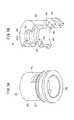
図1に示す本実施形態に係る薬液投与システム10は、薬液Mを生体内に投与するために使用される。薬液投与システム10は、薬液Mを充填可能な薬液容器を構成する筒体16(バレル)と、筒体16を収容したハウジング18とを有する薬液投与装置12と、筒体16に接続可能なコネクタ30を有する投与器具14とを備える。本実施形態では、製品提供状態で予め薬液Mが筒体16内に充填されている。 The drug
薬液投与装置12は、筒体16内に充填された薬液Mを押し子機構の押圧作用下に比較的長い時間(例えば、数分〜数時間程度)をかけて持続的に生体内に投与する。薬液投与装置12は、薬液Mを間欠的に生体内に投与してもよい。薬液Mとしては、例えば、タンパク質製剤、麻薬性鎮痛薬、利尿薬等が挙げられる。 The drug
図1に示すように、薬液投与装置12の使用時において、薬液投与装置12には投与器具14として例えばパッチ式の針付きチューブ15が接続され、筒体16から吐出された薬液Mが針付きチューブ15を介して患者の体内に注入される。 As shown in FIG. 1, when the drug
詳細は図示しないが、薬液投与装置12は、さらに、筒体16内に摺動可能に配置されたガスケットと、ガスケットに接続された押し子機構と、押し子機構を駆動する駆動部と、薬液投与装置12の動作に必要な電力を供給する電池と、駆動部を制御する制御部とを備える。押し子機構、駆動部、電池及び制御部は、ハウジング18内に収容されている。 Although details are not shown, the chemical
図3において、筒体16は、内部に薬液室16aを有する中空円筒状に形成されている。具体的に、筒体16は、その軸方向に内径及び外径が一定の胴部16bと、胴部16bの先端から先端方向に向かって内径及び外径がテーパ状に縮径する肩部16cと、肩部16cから先端方向に突出した先端筒部16dとを有する。 In FIG. 3, the
胴部16bの基端には基端開口16eが形成されている。先端筒部16dには、薬液室16aと連通する先端開口部16fが形成されている。薬液Mは筒体16内に予め充填されている。 A
先端筒部16dの基端部外周には、後述する固定部材26のガタツキを防止するガタツキ防止凸部16gが設けられている。ガタツキ防止凸部16gは、径方向外方に膨出し且つ周方向に一周延在する環状に形成されている。ガタツキ防止凸部16gの基端は、肩部16cの先端に連なっている。 On the outer periphery of the base end portion of the
図2に示すように、先端筒部16dの外周部において、ガタツキ防止凸部16gよりも先端側(先端筒部16dの先端面とガタツキ防止凸部16gとの間)には、固定部材26の係合ツメ26aが係合する係合凸部16hが設けられている。係合凸部16hは、径方向外方に突出し且つ周方向に一周延在する環状に形成されている。係合凸部16hは、係合ツメ26aが係止される係止面16h1と、係止面16h1よりも先端側に形成されるとともに先端方向に向かって縮径する傾斜面16h2とを有する。 As shown in FIG. 2, on the outer peripheral portion of the
ハウジング18は、筒体16を保持するハウジング本体20と、ハウジング本体20から突出するとともに先端筒部16dの外周面を囲み、先端筒部16dと略同心的に配置されたガイド筒部22とを有する。上述した押し子機構、駆動部、電池及び制御部は、ハウジング本体20内に収容されている。図1及び図2において、ガイド筒部22は、ハウジング本体20と一体成形されている。なお、ガイド筒部22は、ハウジング本体20とは別部品として製作され、ハウジング本体20に固定された部材であってもよい。 The
ガイド筒部22は、中空円筒形に形成されており、先端筒部16dと同心状に配置されている。図2において、ガイド筒部22の外周面22aは、外径が先端方向に向かって減少するテーパ状である。なお、ガイド筒部22の外周面22aは、外径が軸方向に一定のストレート形状であってもよい。ガイド筒部22の先端面22bは、先端筒部16dの先端面よりも先端側に位置する。 The
図1において、ハウジング18は上面18aと底面18bを有する。薬液投与装置12は、例えば、患者の皮膚に貼り付けて使用するパッチタイプとして構成され得る。このようなパッチタイプの場合、ハウジング18の底面18bには、皮膚に貼着可能なシート状の貼着部(粘着部)が設けられる。薬液投与装置12の初期状態で貼着部の貼着面には剥離可能な保護シートが貼り付けられる。 In FIG. 1, the
なお、薬液投与装置12は、ハウジング18の底面18bにフックやクリップ等の装着具が設けられ、患者の衣服(例えば、ズボンのウエスト部分等)に引っ掛ける等して取り付けるタイプとして構成されてもよい。また、薬液Mが充填された筒体16と、筒体16内に摺動可能に配置されたガスケットと、押し子機構は、予め組み合わさっており、使用時にハウジング18に挿入される形態でもよい。この場合、押し子機構を筒体16に装着するための装着部が、押し子機構及び筒体16に設けられていることが好ましい。 The drug
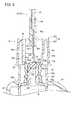
図1及び図2に示すように、薬液投与装置12は、さらに、筒体16の先端開口部16fを液密に封止する弾性材料からなる封止部材24と、筒体16の先端開口部16fが設けられた先端筒部16dに封止部材24を固定する固定部材26とを備える。 As shown in FIGS. 1 and 2, the chemical
封止部材24は、ゴム材やエラストマー材等の弾性樹脂材料からなり、先端筒部16dの先端面16deと密着することにより、先端開口部16fを液密に封止する栓体である。図2及び図4に示すように、封止部材24は、厚さ方向の中央部を構成する封止基部24aと、封止基部24aの先端面から先端方向に突出した先端凸部24bと、封止基部24aの基端面から基端方向に突出した基端凸部24cとを有する。 The sealing
封止基部24a、先端凸部24b及び基端凸部24cの軸方向に垂直な断面形状は、いずれも円形である。先端凸部24b及び基端凸部24cの外径は、封止基部24aの外径よりも小さい。 The cross-sectional shapes of the sealing
図2において、先端凸部24bは、固定部材26の先端よりも先端方向に突出している。封止部材24の外周部(封止基部24aの外周部)は、先端筒部16dの先端面と固定部材26の先端部内面(後述する挟持部26dの基端面)との間に挟まれて軸方向に圧縮されている。このため、封止基部24aの外周部の先端面24a1は、挟持部26dの基端面に液密に密着している。封止基部24aの外周部の基端面24a2は、先端筒部16dの先端面に液密に密着している。 In FIG. 2, the tip
弾性変形する前の自然状態で、先端凸部24b及び基端凸部24cは、軸方向に対称形状である。すなわち、先端凸部24b及び基端凸部24cは、外径及び封止基部24aからの突出高さが、互いに同じである。 In the natural state before elastic deformation, the tip
基端凸部24cの外径は、弾性変形する前の自然状態で先端筒部16dの内径よりも大きいが、図2では基端凸部24cが弾性変形して先端筒部16dの内部に入り込んでいる(嵌合している)。このため、基端凸部24cは、先端筒部16dの内周面に液密に密着している。なお、基端凸部24cは、先端筒部16dの内周面に液密に密着しない形状でもよい。この場合、基端凸部24cの外径は、先端筒部16dの内径よりも小さくなる。また、先端凸部24bの外径は、基端凸部24cと同様に、先端筒部16dの内径よりも小さくなる。 The outer diameter of the base end
固定部材26は、先端筒部16dを覆うように先端筒部16dに装着された中空円筒形の部材であり、先端筒部16dとの間に封止部材24を保持している。図5Bに示すように、固定部材26の内周面には、径方向内方に突出した係合ツメ26aが設けられている。係合ツメ26aは、周方向に間隔を置いて複数設けられている。固定部材26の周壁部26bには、係合ツメ26aの先端側に隣接する位置にツメ成型用孔部26cが設けられている。ツメ成型用孔部26cが設けられることにより、係合ツメ26aを有する固定部材26を射出成型により容易に製作することができる。 The fixing
固定部材26の先端部には、径方向内方に突出した挟持部26dが設けられている。挟持部26dの内周面によって挟持部26dの中央部を軸方向に貫通する先端孔部26d1が形成されている。固定部材26の内周面には、径方向内方に膨出した環状の係止突起26eが設けられている。 A holding
係止突起26eは、固定部材26が先端筒部16dに取り付けられる前に固定部材26からの封止部材24の脱落を阻止するための突起である。係止突起26eは、挟持部26dと係合ツメ26aとの間に形成されている。 The locking
固定部材26の外周部には、コネクタ30の後述する係合部54が係合可能な係合突起26fが設けられている。係合突起26fは、径方向外方に突出し且つ周方向に一周延在する環状に形成されている。係合突起26fは、係合ツメ26aよりも基端側に設けられている。係合突起26fは、先端筒部16dに設けられていてもよい。 The outer peripheral portion of the fixing
図2において、固定部材26の基端面26gは、筒体16に近接又は当接している。具体的に、固定部材26の基端面26gは、肩部16cの先端面に近接又は当接している。固定部材26の基端部内周面26hは、先端筒部16dの外周面に近接又は当接している。具体的に、固定部材26の基端部内周面26hは、ガタツキ防止凸部16gの外周面に近接又は当接している。 In FIG. 2, the
針付きチューブ15は、筒体16の先端筒部16dに接続可能なコネクタ30と、一端部がコネクタ30に接続された可撓性を有する送液チューブ32と、送液チューブ32の他端に接続され患者の皮膚に貼着可能な図示しないパッチ部と、パッチ部から突出した図示しない注入針とを備える。注入針は患者の皮膚に穿刺される。 The needle-attached
なお、薬液投与装置12に接続される投与器具14は上述したパッチ式の針付きチューブ15に限られず、例えば、送液チューブ32の先端に穿刺針(翼状針等)が接続されたものであってもよい。あるいは、投与器具14は、送液チューブ32を介さずに筒体16の先端筒部16dに接続可能な屈曲した針であってもよい。この場合、屈曲した針は、例えば筒体16の先端筒部16dから下方に略90°屈曲しており、薬液投与装置12の皮膚への固定(貼り付け)に伴い皮膚に対して垂直に穿刺される。 The
図2に示すように、コネクタ30は、ガイド筒部22に嵌合可能なコネクタ本体34と、コネクタ本体34に保持されるとともに封止部材24を刺通可能な針管36とを有する。コネクタ本体34は、針先36bが自由端となるように針管36を保持する基部38aを有する針ハブ部材38と、基部38aから針管36の外周面を囲むように突出するとともに針管36と略同心的に配置されたガイド受筒部40a(保護筒部)を有するガイド部材40とを備える。基部38aは、針管36が接続された針接続部42と、針接続部42と同軸上に設けられるとともに送液チューブ32が接続されたチューブ接続部44と、針接続部42の外周面から突出したフランジ部46とを備える。 As shown in FIG. 2, the
図6Bに示すように、針接続部42には、針管36を保持する直線状の針保持孔42aが形成されている。針保持孔42aの基端部内面には、断面が凹凸状(波形状)の粗面領域42bが設けられている。粗面領域42bが設けられているため、針管36が接着剤で針接続部42に接合される場合に、接合強度を向上させることができる。 As shown in FIG. 6B, the
針接続部42の基端部には、基端方向に向かって内径が増大するテーパ状凹部42cが設けられている。針管36が接着剤で針接続部42に接合される場合、テーパ状凹部42cが接着剤溜まりとして機能するため、接合強度を向上させることができる。 The base end portion of the
チューブ接続部44には、送液チューブ32を保持する直線状のチューブ保持孔44aが形成されている。チューブ保持孔44aは、軸方向に内径が一定のストレート部44a1と、先端方向に向かって内径が増大するテーパ部44a2とを有する。テーパ部44a2が設けられているため、組立工程において送液チューブ32をチューブ保持孔44aに挿入する際に、送液チューブ32を挿入しやすい。また、送液チューブ32が接着剤でチューブ接続部44に接合される場合、テーパ部44a2が接着剤溜まりとして機能するため、接合強度を向上させることができる。 The
フランジ部46は、針接続部42の外周面から径方向外方に突出し且つ周方向に一周する円環状に形成されている。フランジ部46は、適宜の接合手段(例えば、接着剤、超音波溶着等)によりガイド受筒部40aに接合されている。上述した針接続部42は、フランジ部46の先端面46a及び基端面46bから軸方向に突出している。図6Aに示すように、フランジ部46の基端面46bには、基端方向に突出する位置決め用凸部48が設けられている。位置決め用凸部48は、基部38aの中心軸を中心とする円周上に配置されている。 The
図6Aにおいて、位置決め用凸部48は、周方向に間隔を置いて複数設けられている。このため、フランジ部46が接着剤によりガイド受筒部40aに接合される場合、周方向に隣接する位置決め用凸部48間に接着剤が入り込むため、接合強度を向上させることができる。なお、位置決め用凸部48は、周方向に一周する円環状に形成されてもよい。位置決め用凸部48が超音波溶着によりガイド受筒部40aに接合される場合、接合面積を稼ぐため、位置決め用凸部48は、周方向に一周する円環状に形成されるのがよい。 In FIG. 6A, a plurality of positioning
図2に示すガイド受筒部40aは、ガイド受筒部40aの外周面に、コネクタ30を筒体16に接続する際にコネクタ30を把持するための把持部50cを有する。コネクタ30を筒体16に接続する際、針先36bが封止部材24に刺さり始める前に、ガイド受筒部40aの内周面は、ガイド筒部22の外周面と当接可能である。ガイド受筒部40aは、基部38aから突出した針管36を囲む中空円筒状の部材であり、基部38aのフランジ部46の基端面46bに接合されている。具体的に、ガイド受筒部40aは、ガイド筒部22の外周面に嵌合可能な円筒状の外側筒部50と、基部38aのフランジ部46に接合された円環状の先端壁52と、基部38aから針管36に沿って突出し、外側筒部50の内側(針管36と外側筒部50との間)に設けられるとともに固定部材26に係合可能な係合部54とを有する。 The guide receiving
外側筒部50の内周面50aは、基端方向に向かって内径が増大するテーパ状に形成されている。なお、外側筒部50の内周面50aは、軸方向に内径が一定のストレート状に形成されていてもよい。外側筒部50の基端には、コネクタ側ガタツキ防止部50bが設けられている。コネクタ側ガタツキ防止部50bは、径方向外方に膨出し且つ周方向に一周する円環状に形成されている。 The inner
先端壁52は、外側筒部50の先端に連なるとともに、基部38aの軸に垂直な板状部である。図7Bに示すように、先端壁52の先端面には、基端方向に凹む円環状の位置決め用凹部56が設けられている。位置決め用凹部56は、基部38aの中心軸を中心とする円周上に配置されている。位置決め用凹部56には、位置決め用凸部48が嵌合するとともに、適宜の接合手段(例えば、接着剤、超音波融着等)により接合されている。 The
なお、上記の構成に代えて、位置決め用凹部56が基部38aのフランジ部46に設けられ、位置決め用凸部48がガイド受筒部40aの先端壁52に設けられてもよい。 Instead of the above configuration, the
係合部54は、コネクタ30を先端筒部16dに接続する際に、先端筒部16dに対する軸方向への相対変位に伴って固定部材26に係合可能に構成されている。コネクタ30を筒体16に接続する際、係合部54は、先端筒部16dとガイド筒部22との間に挿入され、かつ、先端筒部16dと係合するように構成されている。係合部54は、固定部材26の係合突起26fを介して先端筒部16dと係合可能である。係合部54は、基部38aから突出した支持筒部58を有する。係合部54は、先端壁52の内端から基端方向に延出した支持筒部58により支持され、支持筒部58の基端から基端方向に延出している。図7Aに示すように、係合部54は、周方向に間隔を置いて複数配置された係合アーム54aと、各係合アーム54aの自由端に設けられるとともに径方向内方に突出したツメ部54bとを有する。係合アーム54aは、支持筒部58の基端から基端方向に延出している。 When the
係合アーム54aは、径方向に弾性変形可能な弾性片として構成されている。ツメ部54bは、固定部材26の係合突起26fに係合可能である。係合アーム54a及びツメ部54bは、基部38aの中心軸(針管36)を中心とする円周に沿う円弧状に形成されている。ツメ部54bは、外側筒部50の基端面(コネクタ側ガタツキ防止部50bの基端面)よりも先端側に配置されている。 The
図2に示すように、針管36は、直線状に構成されるとともに、内腔36aを有する中空針管であり、内腔36aが送液チューブ32の内腔と連通している。針管36は、基部38a(針接続部42)から基端方向に突出した部分を有するとともに、突出側の端部に鋭利な針先36bを有する。針管36が封止部材24を刺通する際に封止部材24を削り取るコアリングを抑制するため、針先36bには、針中心軸側に曲がる屈曲形状が付けられていてもよい。 As shown in FIG. 2, the
次に、上記のように構成された薬液投与システム10の作用を説明する。 Next, the operation of the drug
薬液投与システム10において、使用前の初期状態では図2に示すように、薬液投与装置12には投与器具14が接続されていない。そこで、薬液投与システム10の使用に際し、薬液投与装置12には投与器具14が接続される。具体的には、コネクタ30が筒体16の先端筒部16dに接続される。 In the drug
そして、薬液投与装置12は、患者の皮膚に貼り付ける、あるいは衣服に装着する等して、患者に取り付けられる。次に、投与器具14の図示しない注入針が患者の皮膚に穿刺される。なお、皮膚への注入針の穿刺前に薬液投与装置12が患者に取り付けられてもよい。 Then, the drug
そして、薬液投与装置12が所定の動作開始指令を受けると、押し子機構によりガスケットが押圧され、筒体16内でガスケットが前進することにより、筒体16内の薬液Mが押し出される。筒体16内から押し出された薬液Mは、患者に穿刺された投与器具14を介して患者の体内に投与(注入)される。 Then, when the chemical
コネクタ30と筒体16の先端筒部16dとの接続は、具体的には、以下のように行われる。 Specifically, the connection between the
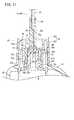
針先36bを筒体16の封止部材24と対向させた状態で、コネクタ30をハウジング18に向かって移動させることにより、コネクタ本体34のガイド受筒部40a内にハウジング18のガイド筒部22を挿入する。具体的には、図8に示すように、コネクタ本体34を先端筒部16d及びガイド筒部22に対向させるとともに針先36bを筒体16の封止部材24と対向させた状態で、コネクタ本体34をハウジング本体20側へと移動させることにより、コネクタ30と先端筒部16dとの接続が開始する。この場合、ハウジング18のガイド筒部22及びコネクタ30の外側筒部50が、嵌合用のガイドとなるため、コネクタ30は先端筒部16dの軸方向に沿って真直ぐ移動することが可能である。すなわち、外側筒部50の内周面50aが、ガイド筒部22の外周面22aによってスライド支持される。 By moving the
図9に示すように、コネクタ30をさらにハウジング本体20側へと移動させると、封止部材24への針管36の穿刺が開始するとともに、係合部54が先端筒部16dとガイド筒部22との間に挿入される。この場合、封止部材24への針管36の穿刺が開始する前(針先36bが封止部材24に接触する前)に、係合部54(具体的には、ツメ部54b)が固定部材26の外周面に接触する。従って、係合部54が固定部材26により支持され始めた後に針管36が穿刺を開始する。このため、針管36が、封止部材24の軸に対して斜めに穿刺されることがない。 As shown in FIG. 9, when the
図10に示すように、コネクタ30をさらにハウジング本体20側へと移動させると、針管36が封止部材24に穿刺される。この結果、針管36は垂直に封止部材24を貫通し、針管36の内腔が筒体16内の薬液室16aと連通する。また、針管36の封止部材24への穿刺と並行して、係合部54のツメ部54bが固定部材26の係合突起26fに押されて、係合アーム54aが外側に撓む(弾性変形する)。 As shown in FIG. 10, when the
図11に示すように、針管36で封止部材24を貫通後に、コネクタ30をさらにハウジング本体20側へと移動させると、係合部54のツメ部54bが固定部材26の係合突起26fを乗り越えて径方向内方に弾性復元することで、係合部54と係合突起26fとの係合が完了する。これにより、コネクタ30と先端筒部16dとの接続(投与器具14と薬液投与装置12との接続)が完了する。コネクタ30と先端筒部16dとの接続が完了した状態では、コネクタ側ガタツキ防止部50bがハウジング本体20の外面に当接する。 As shown in FIG. 11, when the
この場合、本実施形態に係る薬液投与システム10は、以下の効果を奏する。 In this case, the drug
薬液投与システム10によれば、コネクタ30と先端筒部16dとの接続時に、コネクタ30が先端筒部16dに対して軸方向に相対移動することにより係合部54が固定部材26に係合するとともに、ハウジング18に設けられたガイド筒部22によりコネクタ本体34がガイドされる。従って、針管36は、封止部材24に対して回転することなく、且つ傾くことなく封止部材24に穿刺される。このため、コネクタ30と先端筒部16dとの接続の際、針管36が封止部材24を削り取るコアリングが発生することを効果的に抑制することができる。 According to the chemical
コネクタ本体34は、針管36を囲む外側筒部50を有し、外側筒部50の内周面50aが、ガイド筒部22の外周面22aに嵌合可能である。この構成により、コネクタ30と先端筒部16dとの接続時に、ガイド筒部22によってコネクタ30をより安定的にガイドすることが可能となる。 The connector
係合部54は、外側筒部50の内側に設けられている。この構成により、係合部54と固定部材26との係合部位を外側筒部50により覆うことができるため、係合部54と固定部材26との係合を確実に維持することが可能となる。 The engaging
係合部54は、周方向に複数配置されたツメ部54bを有する。この構成により、係合部54が適度な力で固定部材26に係合することができ、容易には外れない係合構造を構築することができる。 The engaging
係合部54は、周方向に間隔を置いて複数配置されるとともに径方向に弾性変形可能な係合アーム54aと、各係合アーム54aの自由端に設けられたツメ部54bとを有する。この構成により、コネクタ30と先端筒部16dとを接続する際の抵抗(接続抵抗)が低減されるため接続が容易である一方、係合時にはツメ部54bが引っ掛かることで接続後には外れにくい係合構造を構築することができる。 A plurality of engaging
係合アーム54a及びツメ部54bは、針管36を中心とする円周に沿う円弧状に形成されている(図7A)。この構成により、係合部54と固定部材26との係合力を効果的に高めることができる。 The
コネクタ30を筒体16に接続する際、係合部54は、固定部材26の外周面上を摺動するように構成されている(図9)。この構成により、コネクタ30と先端筒部16dとの接続の際、針管36が封止部材24に対して傾くことが一層抑制されるため、コアリングの発生をより効果的に抑制することができる。 When the
コネクタ30を筒体16に接続する際、針先36bが封止部材24に刺さり始める前に、係合部54は、固定部材26の外周面に接触するように構成されている(図9)。この構成により、針管36が傾いた状態で封止部材24に穿刺されることがないため、コアリングの発生をより効果的に抑制することができる。 When connecting the
ハウジング本体20は、ガイド筒部22の基端に隣接する当接外周面20aを有し、コネクタ30と先端筒部16dとの接続完了状態で、コネクタ本体34のガイド受筒部40aの突出端部は、ハウジング18に当接するように構成されている(図11)。この構成により、コネクタ30と先端筒部16dとの接続後、薬液投与装置12の使用中にコネクタ30とハウジング18との接続部にガタツキが発生することが抑制される。このため、ユーザに不安感を与えることがないとともに、液密性の低下を防止することが可能となる。 The
先端筒部16dは、胴部16bの外径よりも小さい外径を有し、筒体16は、胴部16bと先端筒部16dとを連結する肩部16cを有し、固定部材26は、先端筒部16dの先端面との間で封止部材24を挟持する挟持部26dと、挟持部26dから基端方向に延びる周壁部26bとを有する。固定部材26の周壁部26bの基端面は、肩部16cの先端面に近接又は当接している(図2)。この構成により、先端筒部16dに対する固定部材26のガタツキが防止されるため、封止部材24と先端筒部16dとの密着性を保持することができる。このため、液密性を良好に維持し、薬液の漏れを防止することができる。 The
先端筒部16dは、先端筒部16dの外周面から径方向外側に向かって突出したガタツキ防止凸部16gを有する。固定部材26の基端面26gは、先端筒部16dのガタツキ防止凸部16gに近接又は当接している。この構成により、先端筒部16dに対する固定部材26のガタツキが防止されるため、封止部材24と先端筒部16dとの密着性を保持することができる。このため、液密性を良好に維持し、薬液Mの漏れを効果的に防止することができる。 The
針ハブ部材38とガイド部材40の先端面の一方には、位置決め用凸部48が設けられ、針ハブ部材38とガイド部材40の先端面の他方には、位置決め用凸部48が嵌合した位置決め用凹部56が設けられている。この構成により、基部38aとガイド受筒部40aとを組み付ける際に、基部38aとガイド受筒部40aとの中心位置合わせを容易に行うことができ、組み付け精度を向上させることができる。 A positioning
封止部材24の外周部(封止基部24a)は、先端筒部16dの先端面16deと固定部材26の先端部内面(挟持部26dの基端面)との間に挟まれて軸方向に圧縮されている。この構成により、封止部材24の高い密着性が得られるため、筒体16の所望の耐圧性を容易に確保することができる。 The outer peripheral portion (sealing
固定部材26の周壁部26bの内周面には、固定部材26が先端筒部16dに取り付けられる前に固定部材26からの封止部材24の脱落を阻止するための係止突起26eが設けられている(図5B)。この構成により、組立工程において固定部材26を先端筒部16dに取り付ける際に、固定部材26内に封止部材24を保持させておくことができる。このため、封止部材24及び固定部材26を先端筒部16dに取り付ける組付作業を容易に行うことができる。 On the inner peripheral surface of the
封止部材24は、固定部材26の先端孔部26d1に挿入され、固定部材26の先端よりも先端方向に突出した先端凸部24bを有する。この構成により、コネクタ30の接続前に、消毒のために、固定部材26から突出した封止部材24の表面(先端凸部24bの先端面)をアルコール綿等で拭き取りやすい。 The sealing
封止部材24は、先端筒部16d内に挿入され、先端筒部16dの内周面により径方向内側に向かって圧縮された基端凸部24cを有するため、封止部材24による液密性を一層向上させることができる。基端凸部24cが径方向内側に向かって圧縮されて基端凸部24cと先端筒部16dの内周面との間に液密シールが形成されているため、先端開口部16fを確実に封止することができる。 Since the sealing
封止部材24は、先端孔部26d1に挿入された先端凸部24bと、先端筒部16d内に挿入された基端凸部24cとを有し、弾性変形する前の自然状態で、先端凸部24b及び基端凸部24cは、軸方向に対称形状である。この構成により、組立工程において先端筒部16dと固定部材26との間に封止部材24を配置する際に、先端凸部24bと基端凸部24cとを識別する必要がないため、簡単に組み付けることができる。 The sealing
本発明は上述した実施形態に限定されるものではなく、本発明の要旨を逸脱しない範囲において、種々の改変が可能である。 The present invention is not limited to the above-described embodiment, and various modifications can be made without departing from the gist of the present invention.
Claims (19)
Translated fromJapanese前記薬液容器に接続可能なコネクタ(30)を有し、前記薬液(M)を患者に送液するための投与器具(14)と、
を備えた薬液投与システム(10)であって、
前記薬液容器は、内部に前記薬液(M)を充填可能な胴部(16b)と、前記胴部(16b)から先端方向に突出し、先端に先端開口部(16f)が設けられた先端筒部(16d)と、を有するバレル(16)と、前記先端開口部(16f)を液密に封止する弾性材料からなる封止部材(24)と、前記封止部材(24)を前記先端筒部(16d)に固定する固定部材(26)とを備え、
前記ハウジング(18)は、前記薬液容器を保持するハウジング本体(20)と、前記ハウジング本体(20)から突出するとともに前記先端筒部(16d)の外周面を囲み、前記先端筒部(16d)と略同心的に配置されたガイド筒部(22)とを有し、
前記コネクタ(30)は、前記封止部材(24)を刺通可能な針先(36b)を有する針管(36)と、前記針管(36)を保持するコネクタ本体(34)とを有し、
前記コネクタ本体(34)は、前記針先(36b)が自由端となるように前記針管(36)を保持する基部(38a)と、前記基部(38a)から前記針管(36)の外周面を囲むように突出するとともに前記針管(36)と略同心的に配置されたガイド受筒部(40a)と、前記基部(38a)から前記針管(36)に沿って突出するとともに前記針管(36)と前記ガイド受筒部(40a)との間に配置され、前記先端筒部(16d)に係合可能な係合部(54)と、を有し、
前記コネクタ(30)を前記薬液容器に接続する際、前記針先(36b)が前記封止部材(24)に刺さり始める前に、前記ガイド受筒部(40a)の内周面は、前記ガイド筒部(22)の外周面と当接可能であり、
前記コネクタ(30)を前記薬液容器に接続する際、前記係合部(54)は、前記先端筒部(16d)と前記ガイド筒部(22)との間に挿入され、かつ、前記先端筒部(16d)と係合するように構成されている
ことを特徴とする薬液投与システム(10)。A chemical solution administration device (12) having a chemical solution container capable of filling the chemical solution (M), a housing (18) containing the chemical solution container, and a chemical solution administration device (12).
An administration device (14) having a connector (30) that can be connected to the drug solution container and for delivering the drug solution (M) to a patient.
It is a drug solution administration system (10) equipped with
The chemical solution container has a body portion (16b) that can be filled with the chemical solution (M) inside, and a tip cylinder portion that protrudes from the body portion (16b) toward the tip and has a tip opening (16f) at the tip. The barrel (16) having (16d), a sealing member (24) made of an elastic material for liquid-tightly sealing the tip opening (16f), and the sealing member (24) are attached to the tip cylinder. A fixing member (26) for fixing to the portion (16d) is provided.
The housing (18) projects from the housing body (20) holding the chemical solution container and the housing body (20) and surrounds the outer peripheral surface of the tip cylinder portion (16d), and the tip cylinder portion (16d). Has a guide tube portion (22) arranged substantially concentrically with the housing.
The connector (30) has a needle tube (36) having a needle tip (36b) capable of penetrating the sealing member (24), and a connector body (34) holding the needle tube (36).
The connector main body (34) has a base portion (38a) for holding the needle tube (36) so that the needle tip (36b) has a free end, and an outer peripheral surface of the needle tube (36) from the base portion (38a). A guide receiving tube portion (40a) that protrudes so as to surround the needle tube (36) and is arranged substantially concentrically with the needle tube (36), and a needle tube (36) that protrudes from the base portion (38a) along the needle tube (36). And an engaging portion (54) arranged between the guide receiving cylinder portion (40a) and engaging with the tip cylinder portion (16d).
When the connector (30) is connected to the chemical solution container, the inner peripheral surface of the guide receiving tube portion (40a) is covered with the guide before the needle tip (36b) begins to pierce the sealing member (24). It can come into contact with the outer peripheral surface of the tubular portion (22) and can come into contact with it.
When the connector (30) is connected to the chemical solution container, the engaging portion (54) is inserted between the tip cylinder portion (16d) and the guide cylinder portion (22), and the tip cylinder portion is inserted. A drug solution administration system (10), characterized in that it is configured to engage with a portion (16d).
前記固定部材(26)は、前記固定部材(26)の外周面に、前記係合部(54)と係合する係合突起(26f)を有し、
前記係合部(54)は、前記固定部材(26)の係合突起(26f)を介して前記先端筒部(16d)と係合可能である、
ことを特徴とする薬液投与システム(10)。In the drug solution administration system (10) according to claim 1,
The fixing member (26) has an engaging projection (26f) that engages with the engaging portion (54) on the outer peripheral surface of the fixing member (26).
The engaging portion (54) can be engaged with the tip cylinder portion (16d) via the engaging projection (26f) of the fixing member (26).
A drug solution administration system (10).
前記ガイド受筒部(40a)は、前記ガイド受筒部(40a)の外周面に、前記コネクタ(30)を前記薬液容器に接続する際に前記コネクタ(30)を把持するための把持部を有する、
ことを特徴とする薬液投与システム(10)。In the drug solution administration system (10) according to claim 2,
The guide receiving cylinder portion (40a) has a gripping portion on the outer peripheral surface of the guide receiving cylinder portion (40a) for gripping the connector (30) when the connector (30) is connected to the chemical liquid container. Have,
A drug solution administration system (10).
前記係合部(54)は、周方向に間隔を置いて複数配置されるとともに径方向に弾性変形可能な係合アーム(54a)と、各前記係合アーム(54a)の自由端部に設けられ、径方向内側に向かって突出したツメ部(54b)とを有する、
ことを特徴とする薬液投与システム(10)。In the drug solution administration system (10) according to any one of claims 1 to 3.
A plurality of the engaging portions (54) are arranged at intervals in the circumferential direction and are provided at the engaging arms (54a) that can be elastically deformed in the radial direction and the free ends of the engaging arms (54a). And has a claw portion (54b) protruding inward in the radial direction.
A drug solution administration system (10).
前記係合部(54)は、前記基部(38a)から突出した支持筒部(58)を有し、
前記係合アーム(54a)は、前記支持筒部(58)の基端から基端方向に延出している、
ことを特徴とする薬液投与システム(10)。In the drug solution administration system (10) according to claim 4,
The engaging portion (54) has a support cylinder portion (58) protruding from the base portion (38a).
The engaging arm (54a) extends from the proximal end of the support cylinder portion (58) toward the proximal end.
A drug solution administration system (10).
前記係合アーム(54a)及び前記ツメ部(54b)は、前記針管(36)を中心とする円周に沿う円弧状に形成されている、
ことを特徴とする薬液投与システム(10)。In the drug solution administration system (10) according to claim 5,
The engaging arm (54a) and the claw portion (54b) are formed in an arc shape along the circumference centered on the needle tube (36).
A drug solution administration system (10).
前記コネクタ(30)を前記薬液容器に接続する際、前記係合部(54)は、前記固定部材(26)の外周面上を摺動するように構成されている、
ことを特徴とする薬液投与システム(10)。In the drug solution administration system (10) according to any one of claims 1 to 6.
When the connector (30) is connected to the chemical solution container, the engaging portion (54) is configured to slide on the outer peripheral surface of the fixing member (26).
A drug solution administration system (10).
前記コネクタ(30)を前記薬液容器に接続する際、前記針先(36b)が前記封止部材(24)に刺さり始める前に、前記係合部(54)は、前記固定部材(26)の前記外周面に接触するように構成されている、
ことを特徴とする薬液投与システム(10)。In the drug solution administration system (10) according to claim 7.
When connecting the connector (30) to the chemical solution container, the engaging portion (54) is attached to the fixing member (26) before the needle tip (36b) begins to pierce the sealing member (24). It is configured to be in contact with the outer peripheral surface.
A drug solution administration system (10).
前記ハウジング本体(20)は、前記ガイド筒部(22)の基端に隣接する当接外周面(20a)を有し、
前記コネクタ(30)と前記薬液容器との接続完了状態で、前記コネクタ本体(34)の前記ガイド受筒部(40a)の突出端部は、前記ハウジング(18)の前記当接外周面(20a)に当接するように構成されている、
ことを特徴とする薬液投与システム(10)。In the drug solution administration system (10) according to any one of claims 1 to 8, the drug solution administration system (10).
The housing body (20) has a contact outer peripheral surface (20a) adjacent to the base end of the guide cylinder portion (22).
When the connection between the connector (30) and the chemical solution container is completed, the protruding end of the guide receiving tube portion (40a) of the connector main body (34) is the contact outer peripheral surface (20a) of the housing (18). ) Is configured to abut,
A drug solution administration system (10).
前記先端筒部(16d)は、前記胴部(16b)の外径よりも小さい外径を有し、
前記薬液容器は、前記胴部(16b)と前記先端筒部(16d)とを連結する肩部(16c)を有し、
前記固定部材(26)は、前記先端筒部(16d)の先端面との間で前記封止部材(24)を挟持する挟持部(26d)と、前記挟持部(26d)から基端方向に延びる周壁部(26b)とを有し、前記固定部材(26)の前記周壁部(26b)の基端面は、前記肩部(16c)の先端面に近接又は当接している、
ことを特徴とする薬液投与システム(10)。In the drug solution administration system (10) according to any one of claims 1 to 9.
The tip cylinder portion (16d) has an outer diameter smaller than the outer diameter of the body portion (16b).
The chemical solution container has a shoulder portion (16c) connecting the body portion (16b) and the tip cylinder portion (16d).
The fixing member (26) has a holding portion (26d) that sandwiches the sealing member (24) with the tip surface of the tip cylinder portion (16d), and the holding portion (26d) in the proximal direction. It has an extending peripheral wall portion (26b), and the base end surface of the peripheral wall portion (26b) of the fixing member (26) is in close proximity to or in contact with the tip surface of the shoulder portion (16c).
A drug solution administration system (10).
前記先端筒部(16d)は、前記先端筒部(16d)の前記外周面から径方向外側に向かって突出したガタツキ防止凸部(16g)を有し、
前記固定部材(26)の周壁部(26b)の内周面は、前記先端筒部(16d)の前記ガタツキ防止凸部(16g)に近接又は当接している、
ことを特徴とする薬液投与システム(10)。In the drug solution administration system (10) according to any one of claims 1 to 10.
The tip cylinder portion (16d) has a rattling prevention convex portion (16 g) protruding radially outward from the outer peripheral surface of the tip cylinder portion (16d).
The inner peripheral surface of the peripheral wall portion (26b) of the fixing member (26) is close to or in contact with the rattling prevention convex portion (16 g) of the tip tubular portion (16d).
A drug solution administration system (10).
前記コネクタ本体(34)は、前記針管(36)を保持する前記基部(38a)を有する針ハブ部材(38)と、前記ガイド受筒部(40a)と前記係合部(54)とを有し、前記針ハブ部材(38)に接合されたガイド部材(40)とを備え、
前記針ハブ部材(38)の基端面と前記ガイド部材(40)の先端面の一方には、位置決め用凸部(48)が設けられ、
前記針ハブ部材(38)とガイド部材(40)の他方には、前記位置決め用凸部(48)が嵌合した位置決め用凹部(56)が設けられている、
ことを特徴とする薬液投与システム(10)。In the drug solution administration system (10) according to any one of claims 1 to 11.
The connector main body (34) has a needle hub member (38) having the base portion (38a) for holding the needle tube (36), the guide receiving tube portion (40a), and the engaging portion (54). A guide member (40) joined to the needle hub member (38) is provided.
A positioning convex portion (48) is provided on one of the proximal end surface of the needle hub member (38) and the distal end surface of the guide member (40).
The other side of the needle hub member (38) and the guide member (40) is provided with a positioning recess (56) into which the positioning protrusion (48) is fitted.
A drug solution administration system (10).
前記固定部材(26)は、前記先端筒部(16d)の先端面との間で前記封止部材(24)を挟持する挟持部(26d)を有し、
前記封止部材(24)の外周部は、前記先端筒部(16d)の前記先端面と前記固定部材(26)の前記挟持部(26d)との間に挟まれて軸方向に圧縮されている、
ことを特徴とする薬液投与システム(10)。In the drug solution administration system (10) according to any one of claims 1 to 12,
The fixing member (26) has a holding portion (26d) for holding the sealing member (24) with the tip surface of the tip cylinder portion (16d).
The outer peripheral portion of the sealing member (24) is sandwiched between the tip surface of the tip cylinder portion (16d) and the holding portion (26d) of the fixing member (26) and compressed in the axial direction. Yes,
A drug solution administration system (10).
前記固定部材(26)は、前記先端筒部(16d)の先端面との間で前記封止部材(24)を挟持する挟持部(26d)と、前記挟持部(26d)から基端方向に延びる周壁部(26b)とを有し、
前記固定部材(26)の前記周壁部(26b)の内周面には、前記固定部材(26)が前記先端筒部(16d)に取り付けられる前に前記固定部材(26)からの前記封止部材(24)の脱落を阻止するための係止突起(26e)が設けられている、
ことを特徴とする薬液投与システム(10)。In the drug solution administration system (10) according to any one of claims 1 to 13.
The fixing member (26) has a holding portion (26d) that sandwiches the sealing member (24) with the tip surface of the tip cylinder portion (16d) and a holding portion (26d) in the proximal direction from the holding portion (26d). It has an extending peripheral wall portion (26b) and
The sealing from the fixing member (26) on the inner peripheral surface of the peripheral wall portion (26b) of the fixing member (26) before the fixing member (26) is attached to the tip cylinder portion (16d). A locking projection (26e) is provided to prevent the member (24) from falling off.
A drug solution administration system (10).
前記固定部材(26)は、前記先端筒部(16d)の先端面との間で前記封止部材(24)を挟持する挟持部(26d)と、前記挟持部(26d)の中央部を軸方向に貫通する先端孔部(26d1)とを有し、
前記封止部材(24)は、前記固定部材(26)の前記先端孔部(26d1)に挿入され、前記固定部材(26)の先端よりも先端方向に突出した先端凸部(24b)を有する、
ことを特徴とする薬液投与システム(10)。In the drug solution administration system (10) according to any one of claims 1 to 14,
The fixing member (26) has a pinching portion (26d) that sandwiches the sealing member (24) between the tip surface of the tip tubular portion (16d) and a central portion of the pinching portion (26d). It has a tip hole (26d1) that penetrates in the direction.
The sealing member (24) has a tip convex portion (24b) that is inserted into the tip hole portion (26d1) of the fixing member (26) and protrudes in the tip direction from the tip of the fixing member (26). ,
A drug solution administration system (10).
前記封止部材(24)は、前記先端筒部(16d)内に挿入され、前記先端筒部(16d)の内周面により径方向内側に向かって圧縮された基端凸部(24c)を有する、
ことを特徴とする薬液投与システム(10)。In the drug solution administration system (10) according to any one of claims 1 to 15,
The sealing member (24) is inserted into the tip cylinder portion (16d), and the base end convex portion (24c) compressed inward in the radial direction by the inner peripheral surface of the tip cylinder portion (16d). Have,
A drug solution administration system (10).
前記固定部材(26)は、前記先端筒部(16d)の先端面との間で前記封止部材(24)を挟持する挟持部(26d)と、前記挟持部(26d)の中央部を軸方向に貫通する先端孔部(26d1)とを有し、
前記封止部材(24)は、前記固定部材(26)の前記先端孔部(26d1)に挿入された先端凸部(24b)と、前記先端筒部(16d)内に挿入された基端凸部(24c)とを有し、
弾性変形する前の自然状態で、前記先端凸部(24b)及び前記基端凸部(24c)は、軸方向に対称形状である、
ことを特徴とする薬液投与システム(10)。In the drug solution administration system (10) according to any one of claims 1 to 14,
The fixing member (26) has a pinching portion (26d) that sandwiches the sealing member (24) between the tip surface of the tip tubular portion (16d) and a central portion of the pinching portion (26d). It has a tip hole (26d1) that penetrates in the direction.
The sealing member (24) has a tip convex portion (24b) inserted into the tip hole portion (26d1) of the fixing member (26) and a proximal end convex portion inserted into the tip cylinder portion (16d). With a portion (24c)
In the natural state before elastic deformation, the tip convex portion (24b) and the proximal end convex portion (24c) have an axially symmetrical shape.
A drug solution administration system (10).
前記薬液容器に設けられた先端筒部(16d)の先端開口部(16f)を封止する封止部材(24)を刺通可能な針先(36b)を有する針管(36)と、前記針管(36)を保持するコネクタ本体(34)とを有し、
前記コネクタ本体(34)は、前記針先(36b)が自由端となるように前記針管(36)を保持する基部(38a)と、前記基部(38a)から前記針管(36)の外周面を囲むように突出するとともに前記針管(36)と略同心的に配置されたガイド受筒部(40a)と、前記基部(38a)から前記針管(36)に沿って突出するとともに前記針管(36)と前記ガイド受筒部(40a)との間に配置され、前記薬液容器の前記先端筒部(16d)に係合可能な係合部(54)と、を有し、
前記コネクタ(30)を前記薬液容器に接続する際、前記針先(36b)が前記封止部材(24)に刺さり始める前に、前記ガイド受筒部(40a)の内周面は、前記ハウジング(18)に設けられたガイド筒部(22)の外周面と当接するように構成されており、
前記コネクタ(30)を前記薬液容器に接続する際、前記係合部(54)は、前記薬液容器の前記先端筒部(16d)と前記ハウジング(18)の前記ガイド筒部(22)との間に挿入され、かつ、前記薬液容器の前記先端筒部(16d)と係合するように構成されている
ことを特徴とするコネクタ(30)。A connector (30) that can be connected to a chemical solution administration device (12) having a chemical solution container that can be filled with the chemical solution (M) and a housing (18) that houses the chemical solution container.
A needle tube (36) having a needle tip (36b) capable of penetrating a sealing member (24) for sealing the tip opening (16f) of the tip tube portion (16d) provided in the chemical solution container, and the needle tube. It has a connector body (34) for holding (36) and has a connector body (34).
The connector main body (34) has a base portion (38a) for holding the needle tube (36) so that the needle tip (36b) has a free end, and an outer peripheral surface of the needle tube (36) from the base portion (38a). A guide receiving tube portion (40a) that protrudes so as to surround the needle tube (36) and is arranged substantially concentrically with the needle tube (36), and a needle tube (36) that protrudes from the base portion (38a) along the needle tube (36). And an engaging portion (54) arranged between the guide receiving cylinder portion (40a) and engaging with the tip cylinder portion (16d) of the chemical liquid container.
When the connector (30) is connected to the chemical solution container, the inner peripheral surface of the guide receiving tube portion (40a) is covered with the housing before the needle tip (36b) begins to pierce the sealing member (24). It is configured to come into contact with the outer peripheral surface of the guide cylinder portion (22) provided in (18).
When the connector (30) is connected to the chemical liquid container, the engaging portion (54) is formed by the tip cylinder portion (16d) of the chemical liquid container and the guide cylinder portion (22) of the housing (18). A connector (30) that is inserted between them and is configured to engage with the tip cylinder portion (16d) of the chemical liquid container.
内部に前記薬液(M)を充填可能な胴部(16b)と、前記胴部(16b)から先端方向に突出し、先端に先端開口部(16f)が設けられた先端筒部(16d)と、を有するバレル(16)と、前記先端開口部(16f)を液密に封止する弾性材料からなる封止部材(24)と、前記封止部材(24)を前記先端筒部(16d)に固定する固定部材(26)とを備える前記薬液容器と、前記薬液容器を保持するハウジング本体(20)と、前記ハウジング本体(20)から突出するとともに前記先端筒部(16d)の外周面を囲み、前記先端筒部(16d)と略同心的に配置されたガイド筒部(22)とを有する前記ハウジング(18)と、を準備し、
前記封止部材(24)を刺通可能な針先(36b)を有する針管(36)と、前記針管(36)を保持するコネクタ本体(34)と、を備え、前記コネクタ本体(34)は、前記針先(36b)が自由端となるように前記針管(36)を保持する基部(38a)と、前記基部(38a)から前記針管(36)の外周面を囲むように突出するとともに前記針管(36)と略同心的に配置されたガイド受筒部(40a)と、前記基部(38a)から前記針管(36)に沿って突出するとともに前記針管(36)と前記ガイド受筒部(40a)との間に配置され、前記先端筒部(16d)に係合可能な係合部(54)と、を有する前記コネクタ(30)を準備し、
前記コネクタ(30)の前記針先(36b)を前記薬液容器の前記封止部材(24)と対向させた状態で、前記コネクタ(30)を前記ハウジング(18)に向かって移動させることにより、前記コネクタ本体(34)の前記ガイド受筒部(40a)内に前記ハウジング(18)の前記ガイド筒部(22)を挿入し、
前記ガイド受筒部(40a)内への前記ガイド筒部(22)の挿入後に、前記針先(36b)を前記封止部材(24)に刺し始めるとともに、前記コネクタ本体(34)の前記係合部(54)を前記先端筒部(16d)と前記ガイド筒部(22)との間に挿入し、
前記針管(36)で前記封止部材(24)を貫通後に、前記係合部(54)と前記先端筒部(16d)とを係合させる、
ことを特徴とする接続方法。A chemical solution administration device (12) having a chemical solution container capable of filling the chemical solution (M), a housing (18) accommodating the chemical solution container, and a connector (30) connectable to the chemical solution container. It is a connection method with an administration device (14) for sending a drug solution (M) to a patient.
A body portion (16b) capable of filling the inside with the chemical solution (M), and a tip cylinder portion (16d) protruding from the body portion (16b) toward the tip end and having a tip opening (16f) at the tip. A sealing member (24) made of an elastic material that liquid-tightly seals the tip opening (16f), and the sealing member (24) is attached to the tip cylinder (16d). The chemical liquid container provided with a fixing member (26) for fixing, a housing main body (20) for holding the chemical liquid container, and a protrusion from the housing main body (20) and surrounding the outer peripheral surface of the tip cylinder portion (16d). The housing (18) having the tip cylinder portion (16d) and the guide cylinder portion (22) arranged substantially concentrically is prepared.
The connector body (34) comprises a needle tube (36) having a needle tip (36b) capable of penetrating the sealing member (24), and a connector body (34) holding the needle tube (36). The base portion (38a) holding the needle tube (36) so that the needle tip (36b) has a free end, and the base portion (38a) projecting from the base portion (38a) so as to surround the outer peripheral surface of the needle tube (36). A guide receiving tube portion (40a) arranged substantially concentrically with the needle tube (36), and projecting from the base portion (38a) along the needle tube (36), and the needle tube (36) and the guide receiving tube portion (36). The connector (30) having an engaging portion (54) disposed between the 40a) and engaging with the tip cylinder portion (16d) is prepared.
By moving the connector (30) toward the housing (18) with the needle tip (36b) of the connector (30) facing the sealing member (24) of the chemical solution container. The guide cylinder portion (22) of the housing (18) is inserted into the guide cylinder portion (40a) of the connector main body (34).
After the guide cylinder portion (22) is inserted into the guide cylinder portion (40a), the needle tip (36b) begins to be pierced into the sealing member (24), and the connector body (34) is engaged. The joint portion (54) is inserted between the tip cylinder portion (16d) and the guide cylinder portion (22).
After penetrating the sealing member (24) with the needle tube (36), the engaging portion (54) and the tip cylinder portion (16d) are engaged with each other.
The connection method is characterized by that.
Applications Claiming Priority (3)
| Application Number | Priority Date | Filing Date | Title |
|---|---|---|---|
| JP2017051395 | 2017-03-16 | ||
| JP2017051395 | 2017-03-16 | ||
| PCT/JP2018/010170WO2018168989A1 (en) | 2017-03-16 | 2018-03-15 | Liquid medicine administration system |
Publications (2)
| Publication Number | Publication Date |
|---|---|
| JPWO2018168989A1 JPWO2018168989A1 (en) | 2020-01-16 |
| JP6975772B2true JP6975772B2 (en) | 2021-12-01 |
Family
ID=63522276
Family Applications (1)
| Application Number | Title | Priority Date | Filing Date |
|---|---|---|---|
| JP2019506254AActiveJP6975772B2 (en) | 2017-03-16 | 2018-03-15 | Drug administration system |
Country Status (2)
| Country | Link |
|---|---|
| JP (1) | JP6975772B2 (en) |
| WO (1) | WO2018168989A1 (en) |
Families Citing this family (3)
| Publication number | Priority date | Publication date | Assignee | Title |
|---|---|---|---|---|
| JP7201663B2 (en)* | 2018-03-20 | 2023-01-10 | テルモ株式会社 | Cap, syringe assembly and manufacturing method thereof |
| WO2020195363A1 (en)* | 2019-03-26 | 2020-10-01 | テルモ株式会社 | Connection structure and liquid medicine administration tool |
| WO2024134964A1 (en)* | 2022-12-22 | 2024-06-27 | テルモ株式会社 | Drug solution dosing device |
Family Cites Families (5)
| Publication number | Priority date | Publication date | Assignee | Title |
|---|---|---|---|---|
| US441661A (en)* | 1890-12-02 | Time-measuring device | ||
| JPS5414477Y2 (en)* | 1973-06-27 | 1979-06-14 | ||
| US4416661A (en)* | 1981-12-24 | 1983-11-22 | Cutter Laboratories, Inc. | Injection site for fluids |
| US9452255B2 (en)* | 2014-07-21 | 2016-09-27 | Medtronic Minimed, Inc. | Smart connection interface |
| US10463847B2 (en)* | 2015-06-11 | 2019-11-05 | Steadymed Ltd. | Infusion set |
- 2018
- 2018-03-15JPJP2019506254Apatent/JP6975772B2/enactiveActive
- 2018-03-15WOPCT/JP2018/010170patent/WO2018168989A1/ennot_activeCeased
Also Published As
| Publication number | Publication date |
|---|---|
| JPWO2018168989A1 (en) | 2020-01-16 |
| WO2018168989A1 (en) | 2018-09-20 |
Similar Documents
| Publication | Publication Date | Title |
|---|---|---|
| CN110325231B (en) | Device and method for injecting a drug | |
| CN114344609B (en) | Cartridge and method of manufacturing a cartridge | |
| EP2543354A1 (en) | Medical device | |
| JP3083134B2 (en) | Cannula sealed shield assembly | |
| JP6975772B2 (en) | Drug administration system | |
| US20110282298A1 (en) | Device for injecting fluid isolated from microneedle hub with dead-space-reducing insert | |
| US20160193412A1 (en) | Drug delivery device | |
| JP2005523118A (en) | Fluid transfer adapter for use with a syringe barrel | |
| CA3172305A1 (en) | Apparatuses and methods for injecting medicaments | |
| JP2014501121A (en) | Injection support device for syringe and injection device | |
| JP2014508562A (en) | Cartridge holder for injection device | |
| CN108472438B (en) | Tortuous fluid path attachment to pre-filled fluid reservoirs | |
| WO2012043162A1 (en) | Medical instrument with attached needle | |
| US20250018166A1 (en) | Liquid medicine administration device | |
| EP3760249B1 (en) | Drug solution administration device | |
| US11938305B2 (en) | Cap, syringe assembly and manufacturing method thereof | |
| WO2024053149A1 (en) | Drug solution administration device | |
| JP7607027B2 (en) | Syringe assembly and drug delivery device | |
| US20250018164A1 (en) | Liquid medicine administration device | |
| US20250018154A1 (en) | Liquid medicine administration device | |
| US20240325631A1 (en) | Cannula assembly for a wearable drug delivery device | |
| US20250018155A1 (en) | Liquid medicine administration device | |
| JP6014395B2 (en) | Drug micro-administration device | |
| WO2019182062A1 (en) | Syringe assembly and prefilled syringe | |
| WO2025202419A1 (en) | A modular patch injection system |
Legal Events
| Date | Code | Title | Description |
|---|---|---|---|
| A621 | Written request for application examination | Free format text:JAPANESE INTERMEDIATE CODE: A621 Effective date:20201009 | |
| A131 | Notification of reasons for refusal | Free format text:JAPANESE INTERMEDIATE CODE: A131 Effective date:20210629 | |
| A521 | Request for written amendment filed | Free format text:JAPANESE INTERMEDIATE CODE: A523 Effective date:20210830 | |
| TRDD | Decision of grant or rejection written | ||
| A01 | Written decision to grant a patent or to grant a registration (utility model) | Free format text:JAPANESE INTERMEDIATE CODE: A01 Effective date:20211012 | |
| A61 | First payment of annual fees (during grant procedure) | Free format text:JAPANESE INTERMEDIATE CODE: A61 Effective date:20211108 | |
| R150 | Certificate of patent or registration of utility model | Ref document number:6975772 Country of ref document:JP Free format text:JAPANESE INTERMEDIATE CODE: R150 | |
| R250 | Receipt of annual fees | Free format text:JAPANESE INTERMEDIATE CODE: R250 |