JP6974313B2 - Ophthalmic instrument system - Google Patents
Ophthalmic instrument systemDownload PDFInfo
- Publication number
- JP6974313B2 JP6974313B2JP2018520563AJP2018520563AJP6974313B2JP 6974313 B2JP6974313 B2JP 6974313B2JP 2018520563 AJP2018520563 AJP 2018520563AJP 2018520563 AJP2018520563 AJP 2018520563AJP 6974313 B2JP6974313 B2JP 6974313B2
- Authority
- JP
- Japan
- Prior art keywords
- instrument
- small diameter
- cannula
- base unit
- support frame
- Prior art date
- Legal status (The legal status is an assumption and is not a legal conclusion. Google has not performed a legal analysis and makes no representation as to the accuracy of the status listed.)
- Expired - Fee Related
Links
Images


Classifications
- A—HUMAN NECESSITIES
- A61—MEDICAL OR VETERINARY SCIENCE; HYGIENE
- A61B—DIAGNOSIS; SURGERY; IDENTIFICATION
- A61B17/00—Surgical instruments, devices or methods
- A61B17/34—Trocars; Puncturing needles
- A61B17/3417—Details of tips or shafts, e.g. grooves, expandable, bendable; Multiple coaxial sliding cannulas, e.g. for dilating
- A61B17/3421—Cannulas
- A61B17/3423—Access ports, e.g. toroid shape introducers for instruments or hands
- A—HUMAN NECESSITIES
- A61—MEDICAL OR VETERINARY SCIENCE; HYGIENE
- A61B—DIAGNOSIS; SURGERY; IDENTIFICATION
- A61B17/00—Surgical instruments, devices or methods
- A61B17/34—Trocars; Puncturing needles
- A61B17/3417—Details of tips or shafts, e.g. grooves, expandable, bendable; Multiple coaxial sliding cannulas, e.g. for dilating
- A61B17/3421—Cannulas
- A—HUMAN NECESSITIES
- A61—MEDICAL OR VETERINARY SCIENCE; HYGIENE
- A61B—DIAGNOSIS; SURGERY; IDENTIFICATION
- A61B17/00—Surgical instruments, devices or methods
- A61B17/32—Surgical cutting instruments
- A—HUMAN NECESSITIES
- A61—MEDICAL OR VETERINARY SCIENCE; HYGIENE
- A61B—DIAGNOSIS; SURGERY; IDENTIFICATION
- A61B17/00—Surgical instruments, devices or methods
- A61B17/34—Trocars; Puncturing needles
- A—HUMAN NECESSITIES
- A61—MEDICAL OR VETERINARY SCIENCE; HYGIENE
- A61F—FILTERS IMPLANTABLE INTO BLOOD VESSELS; PROSTHESES; DEVICES PROVIDING PATENCY TO, OR PREVENTING COLLAPSING OF, TUBULAR STRUCTURES OF THE BODY, e.g. STENTS; ORTHOPAEDIC, NURSING OR CONTRACEPTIVE DEVICES; FOMENTATION; TREATMENT OR PROTECTION OF EYES OR EARS; BANDAGES, DRESSINGS OR ABSORBENT PADS; FIRST-AID KITS
- A61F9/00—Methods or devices for treatment of the eyes; Devices for putting in contact-lenses; Devices to correct squinting; Apparatus to guide the blind; Protective devices for the eyes, carried on the body or in the hand
- A61F9/007—Methods or devices for eye surgery
- A61F9/00736—Instruments for removal of intra-ocular material or intra-ocular injection, e.g. cataract instruments
- A—HUMAN NECESSITIES
- A61—MEDICAL OR VETERINARY SCIENCE; HYGIENE
- A61B—DIAGNOSIS; SURGERY; IDENTIFICATION
- A61B17/00—Surgical instruments, devices or methods
- A61B2017/00477—Coupling
- A—HUMAN NECESSITIES
- A61—MEDICAL OR VETERINARY SCIENCE; HYGIENE
- A61B—DIAGNOSIS; SURGERY; IDENTIFICATION
- A61B17/00—Surgical instruments, devices or methods
- A61B2017/00535—Surgical instruments, devices or methods pneumatically or hydraulically operated
- A61B2017/00544—Surgical instruments, devices or methods pneumatically or hydraulically operated pneumatically
- A—HUMAN NECESSITIES
- A61—MEDICAL OR VETERINARY SCIENCE; HYGIENE
- A61B—DIAGNOSIS; SURGERY; IDENTIFICATION
- A61B17/00—Surgical instruments, devices or methods
- A61B17/34—Trocars; Puncturing needles
- A61B2017/347—Locking means, e.g. for locking instrument in cannula
Landscapes
- Health & Medical Sciences (AREA)
- Surgery (AREA)
- Life Sciences & Earth Sciences (AREA)
- Animal Behavior & Ethology (AREA)
- General Health & Medical Sciences (AREA)
- Engineering & Computer Science (AREA)
- Biomedical Technology (AREA)
- Heart & Thoracic Surgery (AREA)
- Nuclear Medicine, Radiotherapy & Molecular Imaging (AREA)
- Veterinary Medicine (AREA)
- Public Health (AREA)
- Medical Informatics (AREA)
- Molecular Biology (AREA)
- Pathology (AREA)
- Ophthalmology & Optometry (AREA)
- Vascular Medicine (AREA)
- Prostheses (AREA)
- Finger-Pressure Massage (AREA)
- Surgical Instruments (AREA)
- Infusion, Injection, And Reservoir Apparatuses (AREA)
Description
Translated fromJapanese本発明は、眼の手術等の外科的処置において概して使用される小径器具に関する。 The present invention relates to small diameter instruments commonly used in surgical procedures such as eye surgery.
眼科手術は、より小さい切開創を形成可能な、より小さい器具を使用すべく進化し続けている。一般的な切開創の大きさは、例えば25ゲージや27ゲージ(直径約0.41mm)であり、器具は今後さらに小さくなると予測される。切開創を小さくすることには多くの利点があり、例えば、外傷を軽減させ、治癒時間を短縮し、創傷の処置時間を短縮し(無縫合)、患者の快適度を大きく向上させる。 Ophthalmic surgery continues to evolve to use smaller instruments that can form smaller incisions. The size of a typical incision is, for example, 25 gauge or 27 gauge (diameter about 0.41 mm), and the instrument is expected to become even smaller in the future. Reducing the incision has many advantages, such as reducing trauma, reducing healing time, reducing wound treatment time (no sutures), and greatly improving patient comfort.
しかしながら、小さい器具にも問題がある。小型器具は径が小さいためかなり柔軟であるが、これは外科医にとっては不都合である。径の比較的大きい器具には非常に小さい「遊び」があるため、外科医が望む場所に器具の先端を正確に配置できる。径の小さい器具では、ワイヤ状の細い器具が屈曲または撓曲し、意図した場所から先端が移動するため、外科医は制御不能であるように感じる。 However, there are also problems with small instruments. Small instruments are fairly flexible due to their small diameter, which is inconvenient for surgeons. Relatively large diameter instruments have very little "play" so that the tip of the instrument can be placed exactly where the surgeon wants. With smaller diameter instruments, the surgeon feels out of control as the thin wire-like instrument bends or bends and the tip moves from the intended location.
小型器具の屈曲や撓曲は、特定の処置、例えば周辺硝子体切除等において、外科医の視認性を確保するために眼球の向きを変える必要がある場合に特に問題となる。眼球の向きの変更は、器具の一部が眼球のある部位に挿入された状態で、器具を患者の頭部に対して動かすことによって行われる。器具の撓み量は、比較的大きい上に外科医にとって予測不能であるため、眼球を正確な位置に戻すことが困難である。また、器具の柔軟性が高すぎて正確に動作しない場合、網膜表面から膜を剥がすような微細な操作は非常に困難となる。 Flexures and flexures of small instruments are especially problematic when certain procedures, such as peripheral vitrectomy, require the orientation of the eyeball to ensure the surgeon's visibility. The orientation of the eyeball is changed by moving the device with respect to the patient's head with a part of the device inserted in a certain part of the eyeball. The amount of deflection of the instrument is relatively large and unpredictable to the surgeon, making it difficult to return the eyeball to the correct position. In addition, if the instrument is too flexible to operate accurately, it will be very difficult to perform fine operations such as peeling the membrane from the surface of the retina.
このため、小径化に対応しつつも、望ましくない撓みを発生させることなく正確な制御を可能とする器具構造が必要とされている。 For this reason, there is a need for an instrument structure that enables accurate control without causing undesired deflection while coping with smaller diameters.
本発明の目的は、上記した問題を解決することができる小径眼科器具を提供することにある。 An object of the present invention is to provide a small-diameter ophthalmic instrument capable of solving the above-mentioned problems.
上記した目的を達成するために、本発明の眼科器具システムは、把持外側面を有している基部ユニットと、前記基部ユニットから延びているとともに、長さを有している小径器具と、スライド可能な支持フレームであって、前記基部ユニットから延びているとともに、支持フレーム軸線に沿って前記小径器具上を延びていることによって、程度の異なる支持を小径器具に対してもたらす、スライド可能な支持フレームと、前記支持フレームの先端部に設けられている係合機構と、眼球に挿入されるカニューレであって、カニューレ軸線と、前記係合機構と係合するように構成されている接合機構と、を有しており、前記支持フレームと係合された状態において支持フレームと同軸に保持されることによって、前記小径器具に対してさらなる支持をもたらすカニューレと、を備えている。 To achieve the above object, the ophthalmic instrument system of the present invention comprises a base unit having a gripping outer surface, a small diameter device extending from the base unit and having a length, and a slide. A slidable support that is a possible support frame that extends from the base unit and extends over the small diameter device along the axis of the support frame to provide varying degrees of support to the small diameter device. A frame, an engagement mechanism provided at the tip of the support frame, a cannula inserted into the eyeball, a cannula axis, and a joining mechanism configured to engage the engagement mechanism. It comprises a cannula that provides further support for the small diameter instrument by being held coaxially with the support frame in a state of being engaged with the support frame.
また、本発明の別の態様によると、眼科器具システムは、把持外側面を有している基部ユニットと、前記基部ユニットから延びているとともに、長さを有している小径器具と、前記基部ユニットの先端部に設けられている係合機構と、眼球に挿入されるカニューレであって、カニューレ軸線と、前記係合機構と係合するように構成されている接合機構と、を有しており、前記基部ユニットと係合された状態において基部ユニットと同軸に保持されることによって、前記小径器具に対してさらなる支持をもたらすカニューレと、を備えている。 Further, according to another aspect of the present invention, the ophthalmic instrument system comprises a base unit having a gripping outer surface, a small diameter instrument extending from the base unit and having a length, and the base. It has an engaging mechanism provided at the tip of the unit, a cannula inserted into the eyeball, a cannula axis, and a joining mechanism configured to engage the engaging mechanism. It is provided with a cannula that provides additional support for the small diameter instrument by being held coaxially with the base unit in a state of being engaged with the base unit.
以下の詳細な説明では、その一部である添付の図面を参照する。図面には、本発明を実施可能とする特定の実施形態が例示されている。図面においては、実質的に同等である部材には複数の図面中にて類似する符号が付されている。これらの実施形態は、当業者が本発明を実施できるように詳細に記載されている。本発明の範囲から逸脱することなく、他の実施形態が実施可能であり、構造的または論理的な変更等も実施可能である。 In the following detailed description, reference is made to the attached drawings which are a part thereof. The drawings illustrate specific embodiments that make the invention feasible. In the drawings, members that are substantially equivalent are designated by similar reference numerals in a plurality of drawings. These embodiments are described in detail so that those skilled in the art can practice the invention. Other embodiments can be implemented without departing from the scope of the present invention, and structural or logical changes and the like can also be implemented.
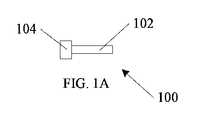
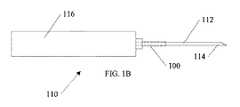
図1Aに、カニューレ100を示す。カニューレ100は、カニューレシャフト102およびヘッド104を有している。図1Bは、使用時のカニューレ100を、トロカールツール110とともに示す。トロカールツール110は、トロカールシャフト112の端部に配置されたブレード114を有している。トロカールシャフト112およびブレード114はハンドル116の端部に取り付けられている。使用時には、図1Bに示すように、カニューレ100がトロカールシャフト112上に配置され、トロカールシャフト112は、カニューレシャフト102およびヘッド104の中心開口を通って延びている。 FIG. 1A shows the
図1Cは、眼球101に挿入された状態のカニューレ100を示す。トロカールシャフト112の端部のブレード114は、眼球101に切開創を形成して、カニューレ100のカニューレシャフト102を挿入可能とするために使用される。ヘッド104は、眼球101の外側に留まり、眼球の外面上に配置される。所定の位置に配置された後、トロカールシャフト112が引き抜かれ、手術中には様々な眼科器具が眼球101に抜き挿しされる。手術終了後には、カニューレ100は取り外される。上述したように、眼球101に対して侵襲性が低く、より早く治癒する小さい切開創を形成することが望ましい。切開創を小さくするためには、カニューレ100を細くする必要があり、そのためには、細いカニューレ内に挿入できる細い眼科器具が必要となる。 FIG. 1C shows the
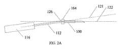
図2Aに、従来技術による眼科器具116を示す。眼科器具116は、小径器具シャフト112を備えている。図2Aは、眼科器具116に横方向の力を加える必要がある場合に、従来器具を用いた手術において起こり得る状態を示している。例えば、眼球の向きを変更するために眼科器具116を押す場合がある。図2Aに示すように、カニューレ100に横方向の力が加えられた場合、カニューレ100のヘッド104付近において小径器具シャフト112に屈曲部126が形成されることがある。外科医は、小径器具シャフト112の先端が軸線121に沿っていると推測しているかもしれない。しかしながら、屈曲部126が形成されているため、小径器具シャフト112の先端は、軸線121ではなく軸線122上に位置している。 FIG. 2A shows an
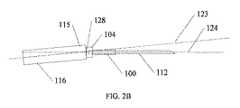
図2Bは、望ましくない屈曲部128が形成されている別の例を示す。眼科器具116のハンドル115がカニューレ100のヘッド104に当接している状態においても、横方向の力によって屈曲部128が形成される場合がある。図2Aと同様に、外科医は、小径器具シャフト112の先端が軸線123に沿っていると推測しているかもしれない。しかしながら、屈曲部128が形成されているため、小径器具シャフト112の先端は、軸線123ではなく軸線124上に位置している。 FIG. 2B shows another example in which the
図3に、本発明の一実施形態による眼科器具300の一実施例を示す。基部ユニット316は、把持外側面317を備えている。基部ユニット316からは小径器具314が延びている。第1の長さ312および第2の長さ310が示されている。後述するように、一実施例においては、第1の長さ312および第2の長さ310が、眼科器具300の使用中に変化するように構成されている。 FIG. 3 shows an embodiment of the
図3には、スライド可能な支持フレーム302も示されている。一実施例において、スライド可能な支持フレーム302の先端部303には、係合機構410が設けられている。係合機構410の機能は、図4Aおよび図4Bを参照して後述する。 FIG. 3 also shows a
図3の例では、スライド可能な支持フレーム302のガイド部が、スライド可能な支持フレーム302と基部ユニット316との間において精密な嵌合をもたらす接続部308を形成している。接続部308は、基部ユニット316内における支持フレーム302の軸方向のスライド移動305を可能としつつも、横方向の遊びを排除もしくは最小化させて、可能な限り支持量を高めるように構成されている。同様に、一実施例においては、小径器具314が、小径器具314とスライド可能な支持フレーム302との間において精密な嵌合をもたらす接続部306を形成している。接続部306は、支持フレーム302内における小径器具314の軸方向のスライド移動を可能としつつも、横方向の遊びを排除もしくは最小化させて、可能な限り支持量を高めるように構成されている。他の実施例では、支持フレーム302とカニューレとが互いに連結していることにより、接続部306において精密な嵌合が不要であり、眼科器具300のねじり動作に対する支持は支持フレーム302およびカニューレによってもたらされているが、これについては後述する。 In the example of FIG. 3, the guide portion of the
図3には、小径器具314の長さに沿った拡張位置に向かって支持フレーム302を付勢する付勢装置304も示されている。付勢装置は、第1の長さ312および第2の長さ310を変化させながら、方向305に沿った支持フレーム302の動きを可能にする。 FIG. 3 also shows an
使用時には、外科医が眼科器具300を眼球側に押して、小径器具314を眼球内のより深い位置に移動させる場合がある。この際には、付勢装置304が、カニューレを軽く押圧し、小径器具314の長さに沿った拡張位置に向かって支持フレーム302を付勢し続ける。小径器具314が眼球にさらに深く押し込まれると、第1の長さ312が増加し、第2の長さ310は減少する。外科医が小径器具314を後退させると、付勢装置304は、支持フレーム302がカニューレに押圧された状態を維持し、第1の長さ312が減少し、第2の長さ310は増加する。小径器具314を眼球に対して抜き挿しすること以外には手動による調整を必要とせずに、第1の長さ310および第2の長さ312が変更される。 At the time of use, the surgeon may push the
図3に示す例においては、付勢装置304はコイルバネであるが、本発明はこれに限定されない。別の実施例においては、付勢装置304は、コイル以外の金属バネ構造を備えている。さらに別の実施例においては、付勢装置304は、圧縮可能なポリマー等の弾性材料を含んでいる。 In the example shown in FIG. 3, the urging
別の実施例において、付勢装置304は空気圧駆動式の付勢装置である。特定の眼科器具システムにおいては、他の機能の空気圧駆動を行うための圧力源がすでに配置されている。このような構成では、既存の圧力源の一部を付勢装置304として容易に使用できる。さらに、空気圧駆動式の付勢装置は、レギュレータまたは他の弁を用いて調整可能とし、付勢力の程度を変更可能としてもよい。 In another embodiment, the urging
図3では、説明を容易にするために、支持フレーム302が、先端部303と基部ユニット316との間を延びる単一のフレーム部材を有している。他の実施例では、先端部と基部ユニット316との間に2つのフレーム部材が延びている。別の実施例においては、小径器具314の周囲に約120度の間隔をおいて配置された3つのフレーム部材が備えられ、あらゆる方向へのねじれに対して支持が高められている。 In FIG. 3, for ease of explanation, the
図4Aおよび図4Bに、眼科器具システムの一実施例における支持機能を示す。図4Aに、カニューレ400および眼科器具300を示す。眼科器具300は、図3に示す眼科器具300に類似している。眼科器具300は、支持フレーム302および付勢装置304を備えている。支持フレーム302の先端部303には、係合機構410が設けられている。カニューレ410は、カニューレシャフト402およびヘッド404を有している。図4Aの例では、ヘッド404は、係合機構410と係合するように構成されている接合機構412を備えている。 4A and 4B show the support function in one embodiment of the ophthalmic instrument system. FIG. 4A shows the
使用時には、小径器具314がカニューレ400に挿入され、接合機構412が図4Bに示すように係合機構410と係合する。図示された例では、接合機構412は、小径器具314の軸方向にスライド移動し、係合機構410に対して容易に出入り可能となっている。しかしながら、ねじり動作420が眼科器具300に加えられると、接合機構412と係合機構410との組み合わせによって、支持フレーム302と同軸上の正しい位置にカニューレ400が保持される。 In use, the
図4Aにおいて、支持フレーム302は拡張状態であり、付勢装置304が拡張している。図4Bにおいては、支持フレーム302は収縮状態であり、付勢装置304が収縮している。 In FIG. 4A, the
図2Aおよび図2Bに示す状態とは異なり、図4Aおよび図4Bに示す構成は、小径器具314に曲げ応力を加えない。ねじり動作420に起因する全ての応力は、互いに連結されている接合機構412および係合機構410によって受容される。 Unlike the states shown in FIGS. 2A and 2B, the configurations shown in FIGS. 4A and 4B do not apply bending stress to the
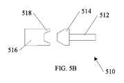
当業者にとっては自明であるが、接合機構412および係合機構410は、多くの異なる構成にて実施可能である。一実施例においては、接合機構412および係合機構410はスプラインを備えている。図5Aおよび5Bに、接合機構412および係合機構410の他の実施例を示す。図5Aに示すカニューレ500は、カニューレシャフト502およびヘッド504を有している。図5Aの例では、接合機構504は雌型であり、支持フレーム506の対応する係合機構508は雄型である。図5Bに示すカニューレ510は、カニューレシャフト512およびヘッド514を有している。図5Bの例では、接合機構514は雄型であり、支持フレーム516の対応する係合機構518は雌型である。 As is obvious to those skilled in the art, the joining
一実施例においては、係合機構はカップ状であり、対応する接合機構は、係合機構のカップ内に密接に嵌合する円柱状である。一実施例においては、横方向の支持を行いながらも、小径器具の軸線を中心に眼科器具が回転する際にカニューレを拘束しないように、カップ状および円柱状等の係合機構および接合機構の組み合わせが設けられていることが効果的である。カニューレが小径器具の軸線を中心に回転した場合、カニューレが切開創を擦り、漏れが生じる可能性がある。しかし、小径器具の軸線を中心とする上記の回転を係合機構および接合機構が許容するように構成されている場合、切開創内でカニューレを回転方向において固定させることが可能であるため、漏れの発生が抑制される。 In one embodiment, the engaging mechanism is cup-shaped and the corresponding joining mechanism is a columnar shape that fits tightly into the cup of the engaging mechanism. In one embodiment, the engaging and joining mechanisms, such as cup-shaped and columnar, are provided so that the cannula is not constrained when the ophthalmic instrument rotates about the axis of the small-diameter instrument while providing lateral support. It is effective that the combination is provided. If the cannula rotates about the axis of the small diameter instrument, the cannula may rub the incision and leak. However, if the engaging and joining mechanisms are configured to allow the above rotation around the axis of the small diameter instrument, the cannula can be fixed in the incision in the rotational direction and thus leak. Is suppressed.
このような回転は、図4Aおよび図4Bに示すねじり動作とは異なる。カップ状部材および円柱状部材を備えた実施例においては、図4Aおよび図4Bに示すような切開創を中心としたねじりが発生している間でもカニューレは支持フレームと同軸に保持されるが、小径器具の軸線を中心とした小径器具の回転は規制されていない。 Such rotation is different from the twisting motion shown in FIGS. 4A and 4B. In an embodiment with a cup-shaped member and a columnar member, the cannula is held coaxially with the support frame while twisting around the incision as shown in FIGS. 4A and 4B. The rotation of the small diameter device around the axis of the small diameter device is not regulated.
図4Aおよび図4Bに示す実施例は付勢装置を備えているが、本発明はこれに限定されない。他の実施例では、カニューレおよび支持フレームにそれぞれ接合機構412および係合機構410が設けられているが、付勢装置は設けられない。さらに別の実施例では、カニューレおよび支持フレームにそれぞれ接合機構412および係合機構410が設けられているが、支持フレームはスライドしないように構成されている。 The embodiments shown in FIGS. 4A and 4B include an urging device, but the present invention is not limited thereto. In another embodiment, the cannula and the support frame are provided with a joining
図6Aおよび6Bに、本発明の一実施形態による眼科器具システム600の別の実施例を示す。図6Aに示すように、基部ユニット610は把持外側面612を備えている。基部ユニット610からは小径器具611が延びている。スライド可能な支持フレーム614は先端部616を有している。一実施例において、スライド可能な支持フレーム614の先端部616には、係合機構618が設けられている。 6A and 6B show another embodiment of the
複数のカニューレ632が、眼球630内に配置されている。カニューレ620は、スライド可能な支持フレーム614の係合機構618と係合する接合機構622を備えている。眼球630内にカニューレシャフト624が延びている。 A plurality of cannula 632s are arranged within the
図6Bには、スライド可能な支持フレーム614が拡張している状態が示されており、この状態において、先端部616がカニューレ620に対して付勢され、支持フレーム614の係合機構618がカニューレ620の接合機構622と係合した状態に維持されている。図6Bにおいては、支持フレーム614が拡張した状態で、小径器具611が眼球630の表面側に引き戻されている。上記の実施例と同様に、眼科器具システム600のねじり動作は、互いに連結された接合機構622および係合機構618によって支持される。カニューレ620は、支持フレーム614の先端部616と同軸に保持され、小径器具を支持する。図6Aおよび図6Bに示す例では、支持フレーム614が、基部ユニット610と先端部616との間に延びる2つのフレーム部材を備えている。前述したように、1つ、3つまたはそれ以上のフレーム部材を含む支持フレーム614の他の構成も本発明の範囲内である。 FIG. 6B shows an expanded state of the
図7に、本発明の一実施形態による使用方法の例を示す。操作702において、基部ユニットに連結された係合機構が、カニューレの接合機構と係合する。カニューレは、基部ユニットと同軸に保持される。操作704において、小径器具が、基部ユニットの第1軸線およびカニューレの第2軸線に沿って、カニューレを介して眼球の切開創に挿入される。上述したように、第1軸線および第2軸線は同軸に維持される。操作706において、小径器具部分の角度が、切開創によって画定される点を中心に眼球表面に対して垂直な平面を基準として調整される。眼科器具は上記の構成を備えているため、前述したように、角度調整によって生じる横方向の力は、係合機構および接合機構によって支持される。 FIG. 7 shows an example of the usage method according to the embodiment of the present invention. In
本明細書が開示する方法および装置の理解を助けるため、非限定的実施形態を以下に列挙する。
実施例1は、眼科器具システムを備えている。このシステムは、把持外側面を有している基部ユニットと、基部ユニットから延びているとともに、長さを有している小径器具と、スライド可能な支持フレームであって、基部ユニットから延びているとともに、支持フレーム軸線に沿って小径器具上を延びていることによって、程度の異なる支持を小径器具に対してもたらす、スライド可能な支持フレームと、支持フレームの先端部に設けられている係合機構と、眼球に挿入されるカニューレであって、カニューレ軸線と、係合機構と係合するように構成されている接合機構と、を有しており、支持フレームと係合された状態において支持フレームと同軸に保持されることによって、小径器具に対してさらなる支持をもたらすカニューレと、を備えている。To aid in understanding the methods and devices disclosed herein, non-limiting embodiments are listed below.
Example 1 comprises an ophthalmic instrument system. The system is a base unit having a grip outer surface, a small diameter instrument that extends from the base unit and has a length, and a slidable support frame that extends from the base unit. Along with, a slidable support frame and an engagement mechanism provided at the tip of the support frame that extend over the small diameter device along the axis of the support frame to provide different degrees of support to the small diameter device. And a cannula inserted into the eyeball, which has a cannula axis and a joining mechanism configured to engage the engagement mechanism, and the support frame in a state of being engaged with the support frame. It is equipped with a cannula, which is held coaxially with and provides additional support for small diameter appliances.
実施例2は、小径器具の長さに沿った拡張位置に向かって支持フレームを付勢する付勢装置をさらに備えている、実施例1に記載の眼科器具システムを含む。
実施例3は、付勢装置がコイルバネを備えている、実施例1または2に記載の眼科器具システムを含む。Example 2 includes the ophthalmologic instrument system of Example 1, further comprising an urging device that urges the support frame towards an extended position along the length of the small diameter instrument.
Example 3 includes the ophthalmologic instrument system according to Example 1 or 2, wherein the urging device comprises a coil spring.
実施例4は、付勢装置が、少なくとも部分的に空気圧によって駆動される、実施例1乃至3のいずれかに記載の眼科器具システムを含む。
実施例5は、係合機構が1つまたは複数のスプラインを備えている、実施例1乃至4のいずれかに記載の眼科器具システムを含む。Example 4 includes the ophthalmic instrument system according to any one of Examples 1 to 3, wherein the urging device is at least partially pneumatically driven.
Example 5 includes the ophthalmologic instrument system according to any one of Examples 1 to 4, wherein the engaging mechanism comprises one or more splines.
実施例6は、係合機構が雌型であり、接合機構が雄型である、実施例1乃至5のいずれかに記載の眼科器具システムを含む。
実施例7は、係合機構がカップ状であり、接合機構が円柱状である、実施例1乃至6のいずれかに記載の眼科器具システムを含む。Example 6 comprises the ophthalmologic instrument system according to any one of Examples 1-5, wherein the engaging mechanism is female and the joining mechanism is male.
Example 7 includes the ophthalmologic instrument system according to any one of Examples 1 to 6, wherein the engaging mechanism is cup-shaped and the joining mechanism is columnar.
実施例8は、眼科器具システムを含む。このシステムは、把持外側面を有している基部ユニットと、基部ユニットから延びているとともに、長さを有している小径器具と、基部ユニットの先端部に設けられている係合機構と、眼球に挿入されるカニューレであって、カニューレ軸線と、係合機構と係合するように構成されている接合機構と、を有しており、基部ユニットと係合された状態において基部ユニットと同軸に保持されることによって、小径器具に対してさらなる支持をもたらすカニューレと、を備えている。 Example 8 includes an ophthalmic instrument system. This system includes a base unit having a gripping outer surface, a small diameter instrument extending from the base unit and having a length, and an engaging mechanism provided at the tip of the base unit. A cannula that is inserted into the eyeball and has a cannula axis and a joining mechanism that is configured to engage the engagement mechanism and is coaxial with the base unit when engaged. It is equipped with a cannula, which provides additional support for small diameter appliances by being held in.
実施例9は、係合機構が、基部ユニットから延びている支持スリーブに設けられている、実施例8に記載の眼科器具システムを含む。
実施例10は、支持スリーブが、小径器具上をスライド可能であることによって、程度の異なる支持を小径器具に対してもたらす、実施例8または9に記載の眼科器具システムを含む。Example 9 includes the ophthalmologic instrument system of Example 8, wherein the engaging mechanism is provided on a support sleeve extending from the base unit.
Example 10 includes the ophthalmologic device system according to Example 8 or 9, wherein the support sleeve is slidable over the small diameter device, thereby providing different degrees of support for the small diameter device.
実施例11は、係合機構が1つまたは複数のスプラインを備えている、実施例8乃至10のいずれかに記載の眼科器具システムを含む。
実施例12は、係合機構が雌型であり、接合機構が雄型である、実施例8乃至11のいずれかに記載の眼科器具システムを含む。Example 11 includes the ophthalmologic instrument system according to any of Examples 8-10, wherein the engaging mechanism comprises one or more splines.
Example 12 includes the ophthalmologic instrument system according to any of Examples 8-11, wherein the engaging mechanism is female and the joining mechanism is male.
実施例13は、係合機構がカップ状であり、接合機構が円柱状である、実施例8乃至12のいずれかに記載の眼科器具システムを含む。
実施例14は、第1軸線を有している基部ユニットに連結されている係合機構を、第2軸線を有しているカニューレの接合機構に係合させることであって、カニューレは基部ユニットと同軸に保持されることと、第1軸線および第2軸線に沿って、カニューレを介して眼球の切開創に小径器具を挿入することと、切開創によって画定される点を中心に眼球の表面に対して垂直な平面を基準として小径器具部分の角度を調整することと、からなる方法であって、角度調節によって生じる横方向の力は係合機構および接合機構によって支持される方法を含む。Example 13 includes the ophthalmologic instrument system according to any of Examples 8-12, wherein the engaging mechanism is cup-shaped and the joining mechanism is columnar.
The fourteenth embodiment is to engage the engaging mechanism connected to the base unit having the first axis to the joining mechanism of the cannula having the second axis, wherein the cannula is the base unit. To be held coaxially with, to insert a small diameter instrument into the incision of the eye through the cannula along the 1st and 2nd axes, and to the surface of the eye centered on the point defined by the incision. A method comprising adjusting the angle of the small diameter instrument portion with respect to a plane perpendicular to the angle, including a method in which the lateral force generated by the angle adjustment is supported by an engaging mechanism and a joining mechanism.
実施例15は、スライド可能な支持フレーム内を通って小径器具を延ばし、眼球内に挿入することと、小径器具の長さに沿って支持フレームを自由にスライドさせることと、をさらに含み、支持フレームの先端部が係合機構を有しており、支持フレームの先端部は、カニューレの接合機構と接した状態に維持されるように付勢装置によって押される、実施例14に記載の方法を含む。 Example 15 further comprises extending and inserting the small diameter device through the slidable support frame and inserting it into the eyeball, and freely sliding the support frame along the length of the small diameter device to support. 14. include.
注入装置の上記および他の実施例および特徴ならびに関連する方法は、上記の詳細な説明において部分的に記載されている。上記の概要は本願の主題の非限定的実施例について記載するものであり、排他的もしくは網羅的な説明ではない。 The above and other examples and features of the infusion device and related methods are partially described in the detailed description above. The above overview describes non-limiting examples of the subject matter of the present application and is not an exclusive or exhaustive description.
上記の詳細な説明は、詳細な説明の一部を構成している添付図面の参照を含む。添付の図面は、本発明を実施可能とする特定の実施形態を例示として示す。これらの実施形態は、本明細書において「実施例」とも呼ばれる。実施例は、図示または説明された要素に加えて他の要素を含む場合がある。しかしながら、発明者らは、図示または記載された要素のみを備えた実施例も意図している。さらに、発明者らは、本明細書にて図示もしくは記載されている特定の実施例(またはその1つもしくは複数の態様)または他の実施例(またはその1つもしくは複数の態様)に対して、図示もしくは記載されている要素(またはその1つもしくは複数の態様)を追加または置換して構成する実施例も意図している。 The detailed description above includes references to the accompanying drawings that form part of the detailed description. The accompanying drawings exemplify specific embodiments that make the invention feasible. These embodiments are also referred to herein as "Examples". Examples may include other elements in addition to the elements illustrated or described. However, the inventors also intend an embodiment comprising only the elements illustrated or described. In addition, the inventors are directed to a particular embodiment (or one or more embodiments thereof) or other embodiments (or one or more embodiments thereof) illustrated or described herein. , An embodiment is also intended to be configured by adding or substituting (or one or more embodiments thereof) the elements shown or described.
特許文書において一般的であるように、本明細書中の「1つの」という表現は、「少なくとも1つ」または「1つまたは複数」という他の例または使用とは無関係に、単数および複数の両方を含むこととする。本明細書において、「または」という用語は、非排他的に用いられ、特に明記しない限り、「AまたはB」には「AであるがBではない」、「BであるがAではない」および「AおよびB」が含まれる。本明細書では、「含む(including)」および「において(in which)」という用語は、それぞれ「備えている(comprising)」および「において(wherein)」に対応する平易な英語表現として使用される。また、以下の特許請求の範囲において、「含んでいる(including)」および「備えている(comprising)」という用語は、限定されていない、すなわち、そのような用語の後に列挙された要素に加えて別の要素を含むシステム、装置、物品、構成、配合および工程も、特許請求の範囲の範囲内にあるとみなされる。さらに、以下の特許請求の範囲において、「第1」、「第2」および「第3」などの用語は単に表示を目的として使用され、それらの用語の対象に数値的な要件を課すことを意図しない。 As is common in patent documents, the expression "one" herein is singular and plural, independent of other examples or uses of "at least one" or "one or more." Both shall be included. In the present specification, the term "or" is used non-exclusively, and unless otherwise specified, "A or B" means "A but not B" or "B but not A". And "A and B" are included. In the present specification, the terms "include" and "in which" are used as plain English expressions corresponding to "comprising" and "wherein", respectively. .. Also, within the scope of the following claims, the terms "include" and "comprising" are not limited, i.e., in addition to the elements listed after such terms. Systems, devices, articles, configurations, formulations and processes that include other elements are also considered to be within the scope of the claims. Furthermore, within the scope of the following claims, terms such as "first", "second" and "third" are used solely for display purposes and impose numerical requirements on the subject of those terms. Not intended.
上記の記載は例示であり、限定的ではない。
例えば、上記の実施例(またはその1つもしくは複数の態様)は、互いに組み合わせて使用してもよい。上記の説明を検討することにより、当業者は他の実施形態を実施できる。要約は、米国特許法施行規則(37 C.F.R 1.72(b))に従って提供され、読者が迅速に技術的開示の性質を確認することを可能にする。特許請求の範囲の範囲または意味を解釈または制限するために要約が用いられることない。また、上記の詳細な説明では、開示を合理化するために様々な特徴がグループ化されている場合があるが、特許請求の範囲に記載されていない開示特徴が、特許請求の範囲において不可欠であることを意図していると解釈されるべきではない。むしろ、本発明の主題は、開示された特定の実施形態のすべての特徴よりも少ない特徴にある。したがって、添付の特許請求の範囲は、詳細な説明に組み込まれ、各請求項は、別個の実施形態として独立しており、そのような実施形態は、様々な組み合わせまたは順列で互いに組み合わせることができる。本発明の範囲は、特許請求の範囲および特許請求の範囲が権利化されるところの均等物の全範囲を参照して決定されるべきである。
The above description is exemplary and not limited.
For example, the above embodiments (or one or more embodiments thereof) may be used in combination with each other. By considering the above description, one of ordinary skill in the art can implement other embodiments. The abstract is provided in accordance with the US Patent Law Enforcement Regulations (37 CFR 1.72 (b)), allowing the reader to quickly confirm the nature of the technical disclosure. No abstract is used to interpret or limit the scope or meaning of the claims. Also, in the above detailed description, various features may be grouped in order to streamline disclosure, but disclosure features not described in the claims are essential in the claims. It should not be construed as intended. Rather, the subject matter of the present invention is less than all the features of the particular embodiments disclosed. Therefore, the appended claims are incorporated into the detailed description, each claim is independent as a separate embodiment, and such embodiments can be combined with each other in various combinations or permutations. .. The scope of the invention should be determined with reference to the scope of claims and the full range of equivalents to which the scope of claims is entitled.
Claims (11)
Translated fromJapanese把持外側面を有している基部ユニットと、
前記基部ユニットから延びているとともに、長さを有している小径器具と、
スライド可能な支持フレームであって、前記基部ユニットから延びているとともに、支持フレーム軸線に沿って前記小径器具上を延びていることによって、程度の異なる支持を小径器具に対してもたらす、スライド可能な支持フレームと、
前記支持フレームの先端部に設けられている係合機構と、
眼球に挿入されるカニューレであって、カニューレ軸線と、前記係合機構と係合するように構成されている接合機構と、を有しており、前記支持フレームと係合された状態において支持フレームと同軸に保持されることによって、前記小径器具に対してさらなる支持をもたらすカニューレと、を備えており、
前記接合機構および係合機構が、横方向の支持を行いながらも、前記支持フレームが回転する際に前記カニューレを拘束しないように、円柱状およびカップ状の形態を有している、眼科器具システム。It ’s an ophthalmic device system.
A base unit having a gripping outer surface and
A small diameter instrument that extends from the base unit and has a length,
A slidable support frame that extends from the base unit and extends over the small diameter device along the axis of the support frame to provide varying degrees of support to the small diameter device. Support frame and
With the engaging mechanism provided at the tip of the support frame,
A cannula that is inserted into the eyeball and has a cannula axis and a joining mechanism that is configured to engage the engagement mechanism, and the support frame is engaged with the support frame. It is equipped with a cannula, which is held coaxially with the small diameter instrument to provide additional support for the small diameter instrument.
An ophthalmic instrument system in which thejoining and engaging mechanisms have a columnar and cup-like shape so as to provide lateral support but not constrain the cannula as the support frame rotates. ..
把持外側面を有している基部ユニットと、
前記基部ユニットから延びているとともに、長さを有している小径器具と、
前記基部ユニットの先端部に設けられている係合機構と、
眼球に挿入されるカニューレであって、カニューレ軸線と、前記係合機構と係合するように構成されている接合機構と、を有しており、前記基部ユニットと係合された状態において基部ユニットと同軸に保持されることによって、前記小径器具に対してさらなる支持をもたらすカニューレと、を備えており、
前記接合機構および係合機構が、横方向の支持を行いながらも、前記基部ユニットが回転する際に前記カニューレを拘束しないように、円柱状およびカップ状の形態を有している、眼科器具システム。It ’s an ophthalmic device system.
A base unit having a gripping outer surface and
A small diameter instrument that extends from the base unit and has a length,
With the engaging mechanism provided at the tip of the base unit,
A cannula that is inserted into the eyeball and has a cannula axis and a joining mechanism that is configured to engage the engagement mechanism, and the base unit is engaged with the base unit. It is equipped with a cannula, which is held coaxially with the small diameter instrument to provide additional support for the small diameter instrument.
An ophthalmic instrument system in which thejoining and engaging mechanisms have a columnar and cup-like shape so as to provide lateral support but not constrain the cannula as the base unit rotates. ..
Applications Claiming Priority (3)
| Application Number | Priority Date | Filing Date | Title |
|---|---|---|---|
| US201562248096P | 2015-10-29 | 2015-10-29 | |
| US62/248,096 | 2015-10-29 | ||
| PCT/US2016/059554WO2017075514A1 (en) | 2015-10-29 | 2016-10-28 | Small gauge ophthalmic instrument and method |
Publications (2)
| Publication Number | Publication Date |
|---|---|
| JP2018531712A JP2018531712A (en) | 2018-11-01 |
| JP6974313B2true JP6974313B2 (en) | 2021-12-01 |
Family
ID=58630889
Family Applications (1)
| Application Number | Title | Priority Date | Filing Date |
|---|---|---|---|
| JP2018520563AExpired - Fee RelatedJP6974313B2 (en) | 2015-10-29 | 2016-10-28 | Ophthalmic instrument system |
Country Status (8)
| Country | Link |
|---|---|
| US (1) | US20190059936A1 (en) |
| EP (1) | EP3367918A4 (en) |
| JP (1) | JP6974313B2 (en) |
| CN (1) | CN108472024A (en) |
| AU (1) | AU2016343784B2 (en) |
| BR (1) | BR112018008770A2 (en) |
| CA (1) | CA3002205A1 (en) |
| WO (1) | WO2017075514A1 (en) |
Families Citing this family (4)
| Publication number | Priority date | Publication date | Assignee | Title |
|---|---|---|---|---|
| US11540941B2 (en) | 2019-12-11 | 2023-01-03 | Alcon Inc. | Adjustable support sleeve for surgical instruments |
| BR112022011125A2 (en) | 2019-12-11 | 2022-08-23 | Alcon Inc | ADJUSTABLE REINFORCEMENT FOR SURGICAL INSTRUMENTS |
| US12186236B2 (en) | 2021-08-26 | 2025-01-07 | Alcon Inc. | Adjustable stiffener for surgical instruments |
| WO2025152025A1 (en)* | 2024-01-16 | 2025-07-24 | 苏州碧利医疗科技有限公司 | Ophthalmic puncture device |
Family Cites Families (12)
| Publication number | Priority date | Publication date | Assignee | Title |
|---|---|---|---|---|
| US4565396A (en) | 1985-03-11 | 1986-01-21 | Larimer John M | Pneumatic contact lens insertion device |
| CN2287027Y (en)* | 1996-09-18 | 1998-08-05 | 张军锋 | Miniature intraocular pressure adjustor for glaucoma |
| US8202277B2 (en)* | 2003-01-29 | 2012-06-19 | Edwin Ryan | Small gauge surgical instrument with support device |
| US9931244B2 (en)* | 2003-01-29 | 2018-04-03 | Edwin Ryan | Small gauge surgical instrument with support device |
| US20040186484A1 (en)* | 2003-01-29 | 2004-09-23 | Edwin Ryan | Small gauge surgical instrument with support device |
| ES2364667T3 (en)* | 2006-08-07 | 2011-09-12 | Oertli-Instrumente Ag | INCISION DEVICE FOR OPHTHALMOLOGY. |
| US20080195135A1 (en)* | 2007-02-12 | 2008-08-14 | Alcon, Inc. | Surgical Probe |
| US20080312662A1 (en)* | 2007-06-13 | 2008-12-18 | Hickingbotham Dyson W | Self Sealing Cannula / Aperture Closure Cannula |
| JP5551395B2 (en)* | 2009-08-28 | 2014-07-16 | マニー株式会社 | Cannula and manufacturing method thereof |
| US8777931B2 (en)* | 2011-08-19 | 2014-07-15 | Alcon Research, Ltd. | Retractable luer lock fittings |
| US20140005640A1 (en)* | 2012-06-28 | 2014-01-02 | Ethicon Endo-Surgery, Inc. | Surgical end effector jaw and electrode configurations |
| AU2014354716B2 (en)* | 2013-11-28 | 2018-12-06 | Alcon Inc. | Ophtalmic surgical systems, methods, and devices |
- 2016
- 2016-10-28BRBR112018008770Apatent/BR112018008770A2/ennot_activeApplication Discontinuation
- 2016-10-28AUAU2016343784Apatent/AU2016343784B2/ennot_activeCeased
- 2016-10-28EPEP16860989.9Apatent/EP3367918A4/ennot_activeWithdrawn
- 2016-10-28JPJP2018520563Apatent/JP6974313B2/ennot_activeExpired - Fee Related
- 2016-10-28CACA3002205Apatent/CA3002205A1/ennot_activeAbandoned
- 2016-10-28WOPCT/US2016/059554patent/WO2017075514A1/ennot_activeCeased
- 2016-10-28USUS15/771,991patent/US20190059936A1/enactivePending
- 2016-10-28CNCN201680063502.6Apatent/CN108472024A/enactivePending
Also Published As
| Publication number | Publication date |
|---|---|
| CN108472024A (en) | 2018-08-31 |
| BR112018008770A2 (en) | 2018-10-30 |
| AU2016343784A1 (en) | 2018-06-07 |
| WO2017075514A1 (en) | 2017-05-04 |
| EP3367918A1 (en) | 2018-09-05 |
| US20190059936A1 (en) | 2019-02-28 |
| AU2016343784B2 (en) | 2021-02-04 |
| JP2018531712A (en) | 2018-11-01 |
| EP3367918A4 (en) | 2019-07-17 |
| CA3002205A1 (en) | 2017-05-04 |
Similar Documents
| Publication | Publication Date | Title |
|---|---|---|
| US20230248401A1 (en) | Spinal screw insertion devices and methods | |
| JP6974313B2 (en) | Ophthalmic instrument system | |
| AU2015298627B2 (en) | Devices for spinal screw insertion | |
| US11980572B2 (en) | Small gauge surgical instrument with adjustable support | |
| JP2007130465A (en) | Surgical probe | |
| US20220241110A1 (en) | Dynamic support for ophthalmic device | |
| JP2017537683A (en) | Secured guide device |
Legal Events
| Date | Code | Title | Description |
|---|---|---|---|
| A521 | Request for written amendment filed | Free format text:JAPANESE INTERMEDIATE CODE: A523 Effective date:20180706 | |
| A621 | Written request for application examination | Free format text:JAPANESE INTERMEDIATE CODE: A621 Effective date:20191017 | |
| A977 | Report on retrieval | Free format text:JAPANESE INTERMEDIATE CODE: A971007 Effective date:20200930 | |
| A131 | Notification of reasons for refusal | Free format text:JAPANESE INTERMEDIATE CODE: A131 Effective date:20201013 | |
| A601 | Written request for extension of time | Free format text:JAPANESE INTERMEDIATE CODE: A601 Effective date:20210113 | |
| A521 | Request for written amendment filed | Free format text:JAPANESE INTERMEDIATE CODE: A523 Effective date:20210305 | |
| TRDD | Decision of grant or rejection written | ||
| A01 | Written decision to grant a patent or to grant a registration (utility model) | Free format text:JAPANESE INTERMEDIATE CODE: A01 Effective date:20211005 | |
| A61 | First payment of annual fees (during grant procedure) | Free format text:JAPANESE INTERMEDIATE CODE: A61 Effective date:20211104 | |
| R150 | Certificate of patent or registration of utility model | Ref document number:6974313 Country of ref document:JP Free format text:JAPANESE INTERMEDIATE CODE: R150 | |
| LAPS | Cancellation because of no payment of annual fees |