JP6974247B2 - Information processing equipment, information presentation instruction method, program, and recording medium - Google Patents
Information processing equipment, information presentation instruction method, program, and recording mediumDownload PDFInfo
- Publication number
- JP6974247B2 JP6974247B2JP2018086903AJP2018086903AJP6974247B2JP 6974247 B2JP6974247 B2JP 6974247B2JP 2018086903 AJP2018086903 AJP 2018086903AJP 2018086903 AJP2018086903 AJP 2018086903AJP 6974247 B2JP6974247 B2JP 6974247B2
- Authority
- JP
- Japan
- Prior art keywords
- information
- terminal
- unmanned aerial
- aerial vehicle
- flying object
- Prior art date
- Legal status (The legal status is an assumption and is not a legal conclusion. Google has not performed a legal analysis and makes no representation as to the accuracy of the status listed.)
- Expired - Fee Related
Links
Images


Classifications
- G—PHYSICS
- G05—CONTROLLING; REGULATING
- G05D—SYSTEMS FOR CONTROLLING OR REGULATING NON-ELECTRIC VARIABLES
- G05D1/00—Control of position, course, altitude or attitude of land, water, air or space vehicles, e.g. using automatic pilots
- G05D1/0011—Control of position, course, altitude or attitude of land, water, air or space vehicles, e.g. using automatic pilots associated with a remote control arrangement
- G05D1/0033—Control of position, course, altitude or attitude of land, water, air or space vehicles, e.g. using automatic pilots associated with a remote control arrangement by having the operator tracking the vehicle either by direct line of sight or via one or more cameras located remotely from the vehicle
- G—PHYSICS
- G05—CONTROLLING; REGULATING
- G05D—SYSTEMS FOR CONTROLLING OR REGULATING NON-ELECTRIC VARIABLES
- G05D1/00—Control of position, course, altitude or attitude of land, water, air or space vehicles, e.g. using automatic pilots
- G05D1/0011—Control of position, course, altitude or attitude of land, water, air or space vehicles, e.g. using automatic pilots associated with a remote control arrangement
- G05D1/0038—Control of position, course, altitude or attitude of land, water, air or space vehicles, e.g. using automatic pilots associated with a remote control arrangement by providing the operator with simple or augmented images from one or more cameras located onboard the vehicle, e.g. tele-operation
- G—PHYSICS
- G05—CONTROLLING; REGULATING
- G05D—SYSTEMS FOR CONTROLLING OR REGULATING NON-ELECTRIC VARIABLES
- G05D1/00—Control of position, course, altitude or attitude of land, water, air or space vehicles, e.g. using automatic pilots
- G05D1/0011—Control of position, course, altitude or attitude of land, water, air or space vehicles, e.g. using automatic pilots associated with a remote control arrangement
- G05D1/0027—Control of position, course, altitude or attitude of land, water, air or space vehicles, e.g. using automatic pilots associated with a remote control arrangement involving a plurality of vehicles, e.g. fleet or convoy travelling
- G—PHYSICS
- G05—CONTROLLING; REGULATING
- G05D—SYSTEMS FOR CONTROLLING OR REGULATING NON-ELECTRIC VARIABLES
- G05D1/00—Control of position, course, altitude or attitude of land, water, air or space vehicles, e.g. using automatic pilots
- G05D1/0094—Control of position, course, altitude or attitude of land, water, air or space vehicles, e.g. using automatic pilots involving pointing a payload, e.g. camera, weapon, sensor, towards a fixed or moving target
- G—PHYSICS
- G05—CONTROLLING; REGULATING
- G05D—SYSTEMS FOR CONTROLLING OR REGULATING NON-ELECTRIC VARIABLES
- G05D1/00—Control of position, course, altitude or attitude of land, water, air or space vehicles, e.g. using automatic pilots
- G05D1/10—Simultaneous control of position or course in three dimensions
- G05D1/101—Simultaneous control of position or course in three dimensions specially adapted for aircraft
- G05D1/104—Simultaneous control of position or course in three dimensions specially adapted for aircraft involving a plurality of aircrafts, e.g. formation flying
- G—PHYSICS
- G05—CONTROLLING; REGULATING
- G05D—SYSTEMS FOR CONTROLLING OR REGULATING NON-ELECTRIC VARIABLES
- G05D1/00—Control of position, course, altitude or attitude of land, water, air or space vehicles, e.g. using automatic pilots
- G05D1/10—Simultaneous control of position or course in three dimensions
- G05D1/101—Simultaneous control of position or course in three dimensions specially adapted for aircraft
- G05D1/106—Change initiated in response to external conditions, e.g. avoidance of elevated terrain or of no-fly zones
- G05D1/1064—Change initiated in response to external conditions, e.g. avoidance of elevated terrain or of no-fly zones specially adapted for avoiding collisions with other aircraft
- G—PHYSICS
- G08—SIGNALLING
- G08G—TRAFFIC CONTROL SYSTEMS
- G08G5/00—Traffic control systems for aircraft
- B—PERFORMING OPERATIONS; TRANSPORTING
- B64—AIRCRAFT; AVIATION; COSMONAUTICS
- B64U—UNMANNED AERIAL VEHICLES [UAV]; EQUIPMENT THEREFOR
- B64U2101/00—UAVs specially adapted for particular uses or applications
- B64U2101/30—UAVs specially adapted for particular uses or applications for imaging, photography or videography
- B—PERFORMING OPERATIONS; TRANSPORTING
- B64—AIRCRAFT; AVIATION; COSMONAUTICS
- B64U—UNMANNED AERIAL VEHICLES [UAV]; EQUIPMENT THEREFOR
- B64U2201/00—UAVs characterised by their flight controls
- B64U2201/20—Remote controls
Landscapes
- Engineering & Computer Science (AREA)
- Aviation & Aerospace Engineering (AREA)
- Physics & Mathematics (AREA)
- General Physics & Mathematics (AREA)
- Radar, Positioning & Navigation (AREA)
- Remote Sensing (AREA)
- Automation & Control Theory (AREA)
- Traffic Control Systems (AREA)
- Control Of Position, Course, Altitude, Or Attitude Of Moving Bodies (AREA)
Description
Translated fromJapanese本開示は、飛行体により撮像された画像におけるユーザの注目点に基づいて情報を提示させる情報処理装置、情報提示指示方法、プログラム、及び記録媒体に関する。 The present disclosure relates to an information processing device, an information presentation instruction method, a program, and a recording medium for presenting information based on a user's point of interest in an image captured by an air vehicle.
従来、ユーザが、無人航空機を目視せずに、例えば端末を用いて、端末のディスプレイに表示された無人航空機による撮像画像を見ながら、無人航空機の飛行を操作する、FPV(First Person View)飛行が知られている(特許文献1参照)。 Conventionally, FPV (First Person View) flight in which a user operates an unmanned aerial vehicle flight without visually observing the unmanned aerial vehicle, for example, using a terminal while viewing an image captured by the unmanned aerial vehicle displayed on the display of the terminal. Is known (see Patent Document 1).
無人航空機をFPV飛行させる場合、ユーザは、撮像画像だけを見ても、無人航空機の周囲の状況を確認しにくい。例えば、複数の無人航空機が同じ目的地に向かって飛行する場合、目的地に近づくにつれて無人航空機同士が接近し、無人航空機同士が衝突するおそれがある。 When an unmanned aerial vehicle is made to fly in FPV, it is difficult for the user to confirm the surrounding situation of the unmanned aerial vehicle only by looking at the captured image. For example, when a plurality of unmanned aerial vehicles fly toward the same destination, the unmanned aerial vehicles may approach each other as they approach the destination, and the unmanned aerial vehicles may collide with each other.
一態様において、情報処理装置は、飛行体により撮像された画像におけるユーザの注目点に基づいて情報を提示させる情報処理装置であって、処理部を備え、処理部は、第1の飛行体の制御を指示する第1の端末を操作する第1のユーザが第1の飛行体により撮像された第1の画像において注目する第1の注目点と、第2の飛行体の制御を指示する第2の端末を操作する第2のユーザが第2の飛行体により撮像された第2の画像において注目する第2の注目点と、を取得し、第1の注目点と第2の注目点が、同じ注目点を示す共通注目点であるか否かを判定し、共通注目点である場合、第1の端末に、第2の飛行体に関する情報を提示させる。 In one aspect, the information processing device is an information processing device that presents information based on a user's point of interest in an image captured by the flying object, and includes a processing unit, wherein the processing unit is a first flying object. A first point of interest in a first image captured by a first flying object by a first user operating a first terminal instructing control, and a second instructing control of the second flying object. The second attention point, which the second user operating the second terminal pays attention to in the second image captured by the second flying object, is acquired, and the first attention point and the second attention point are obtained. , It is determined whether or not it is a common attention point indicating the same attention point, and if it is a common attention point, the first terminal is made to present information about the second flying object.
処理部は、第1の飛行体が移動しているか否かを判定し、第1の飛行体が移動している場合、第1の端末に、第2の飛行体に関する情報を提示させてよい。 The processing unit may determine whether or not the first flying object is moving, and if the first flying object is moving, have the first terminal present information about the second flying object. ..
処理部は、第1の飛行体の位置情報を取得し、第2の飛行体の位置情報を取得し、第1の飛行体と第2の飛行体との距離である第1の距離が第1の閾値以下である場合、第1の端末に、第2の飛行体に関する情報を提示させてよい。 The processing unit acquires the position information of the first air vehicle, acquires the position information of the second air vehicle, and the first distance, which is the distance between the first air vehicle and the second air vehicle, is the first. If it is less than or equal to the threshold of 1, the first terminal may be made to present information about the second flying object.
処理部は、第1の飛行体の位置情報を取得し、第2の飛行体の位置情報を取得し、第1の端末の画面における、第1の飛行体の位置に対する第2の飛行体の位置に基づく位置に、第2の飛行体の存在を示す情報を提示させてよい。 The processing unit acquires the position information of the first air vehicle, acquires the position information of the second air vehicle, and of the second air vehicle with respect to the position of the first air vehicle on the screen of the first terminal. The position-based position may present information indicating the presence of the second aircraft.
処理部は、第1の飛行体の位置情報を取得し、第2の飛行体の位置情報を取得し、第1の飛行体と第2の飛行体との距離である第1の距離が第1の閾値以下である場合、第1の端末に、第1の飛行体による飛行の速度を制限することを推奨する第1の推奨情報を提示させてよい。 The processing unit acquires the position information of the first air vehicle, acquires the position information of the second air vehicle, and the first distance, which is the distance between the first air vehicle and the second air vehicle, is the first. If it is less than or equal to the threshold of 1, the first terminal may be made to present the first recommended information recommending limiting the speed of flight by the first flying object.
処理部は、第1の距離が短い程、第1の飛行体による飛行の速度を低速に制限することを推奨する第1の推奨情報を提示させてよい。 The processing unit may present first recommended information that recommends limiting the speed of flight by the first flying object to a lower speed as the first distance is shorter.
処理部は、共通注目点の位置情報を取得し、第1の飛行体の位置情報を取得し、共通注目点と第1の飛行体との距離である第2の距離が第2の閾値以下である場合、第1の端末に、第1の飛行体による飛行の速度を制限することを推奨する第2の推奨情報を提示させてよい。 The processing unit acquires the position information of the common attention point, acquires the position information of the first flying object, and the second distance, which is the distance between the common attention point and the first flying object, is equal to or less than the second threshold value. If so, the first terminal may be made to present a second recommendation information that recommends limiting the speed of flight by the first aircraft.
処理部は、第2の距離が短い程、第1の飛行体による飛行の速度を低速に制限することを推奨する第2の推奨情報を提示させてよい。 The processing unit may present a second recommendation information that recommends limiting the speed of flight by the first aircraft to a lower speed as the second distance is shorter.
情報処理装置は、サーバでよく、通信部、を更に備えてよい。処理部は、通信部を介して、第1の端末から第1の注目点を取得し、第2の端末から第2の注目点を取得し、通信部を介して、第1の端末に提示させる情報を第1の端末へ送信してよい。 The information processing device may be a server, and may further include a communication unit. The processing unit acquires the first attention point from the first terminal via the communication unit, acquires the second attention point from the second terminal, and presents it to the first terminal via the communication unit. The information to be made may be transmitted to the first terminal.
情報処理装置は、第1の端末であり、通信部及び提示部、を更に備えてよい。処理部は、通信部を介して、第1の飛行体から第1の画像を取得し、第1の画像における第1の注目点を検出し、通信部を介して、第2の端末から第2の注目点を取得し、第1の端末に提示させる情報を、提示部に提示させてよい。 The information processing device is a first terminal, and may further include a communication unit and a presentation unit. The processing unit acquires the first image from the first flying object via the communication unit, detects the first point of interest in the first image, and uses the communication unit to obtain the first image from the second terminal. The presenting unit may be made to present the information to be presented to the first terminal by acquiring the attention point of 2.
一態様において、情報提示指示方法は、飛行体により撮像された画像におけるユーザの注目点に基づいて情報を提示させる情報提示指示方法であって、第1の飛行体の制御を指示する第1の端末を操作する第1のユーザが第1の飛行体により撮像された第1の画像において注目する第1の注目点と、第2の飛行体の制御を指示する第2の端末を操作する第2のユーザが第2の飛行体により撮像された第2の画像において注目する第2の注目点と、を取得するステップと、第1の注目点と第2の注目点が、同じ注目点を示す共通注目点であるか否かを判定するステップと、共通注目点である場合、第1の端末に、第2の飛行体に関する情報を提示させるステップと、を含む。 In one aspect, the information presentation instruction method is an information presentation instruction method for presenting information based on a user's point of interest in an image captured by the flying object, and is a first method for instructing control of the first flying object. A first user who operates a terminal operates a first point of interest in a first image captured by the first flying object, and a second terminal instructing control of the second flying object. The step of acquiring the second attention point, which the second user pays attention to in the second image captured by the second flying object, and the first attention point and the second attention point have the same attention point. It includes a step of determining whether or not it is a common attention point to be indicated, and, if it is a common attention point, a step of causing a first terminal to present information about a second flying object.
情報提示指示方法は、第1の飛行体が移動しているか否かを判定するステップ、を更に含んでよい。第2の飛行体に関する情報を提示させるステップは、第1の飛行体が移動している場合、第1の端末に、第2の飛行体に関する情報を提示させるステップを含んでよい。 The information presentation instruction method may further include a step of determining whether or not the first flying object is moving. The step of presenting information about the second air vehicle may include a step of causing the first terminal to present information about the second air vehicle when the first air vehicle is moving.
情報提示指示方法は、第1の飛行体の位置情報を取得するステップと、第2の飛行体の位置情報を取得するステップと、を更に含んでよい。第2の飛行体に関する情報を提示させるステップは、第1の飛行体と第2の飛行体との距離である第1の距離が第1の閾値以下である場合、第1の端末に、第2の飛行体に関する情報を提示させるステップを含んでよい。 The information presentation instruction method may further include a step of acquiring the position information of the first flying object and a step of acquiring the position information of the second flying object. The step of presenting information about the second flying object is a step of causing the first terminal to present the first distance, which is the distance between the first flying object and the second flying object, when the first distance is equal to or less than the first threshold value. It may include a step of presenting information about the aircraft of 2.
情報提示指示方法は、第1の飛行体の位置情報を取得するステップと、第2の飛行体の位置情報を取得するステップと、を更に含んでよい。第2の飛行体に関する情報を提示させるステップは、第1の端末の画面における、第1の飛行体の位置に対する第2の飛行体の位置に基づく位置に、第2の飛行体の存在を示す情報を提示させるステップを含んでよい。 The information presentation instruction method may further include a step of acquiring the position information of the first flying object and a step of acquiring the position information of the second flying object. The step of presenting information about the second flying object indicates the presence of the second flying object at a position based on the position of the second flying object with respect to the position of the first flying object on the screen of the first terminal. It may include a step of presenting information.
情報提示指示方法は、第1の飛行体の位置情報を取得するステップと、第2の飛行体の位置情報を取得するステップと、第1の飛行体と第2の飛行体との距離である第1の距離が第1の閾値以下である場合、第1の端末に、第1の飛行体による飛行の速度を制限することを推奨する第1の推奨情報を提示させるステップと、を更に含んでよい。 The information presentation instruction method is a step of acquiring the position information of the first flying object, a step of acquiring the position information of the second flying object, and a distance between the first flying object and the second flying object. Further including, when the first distance is less than or equal to the first threshold, a step of having the first terminal present a first recommendation information recommending limiting the speed of flight by the first aircraft. It's fine.
第1の推奨情報を提示させるステップは、第1の距離が短い程、第1の飛行体による飛行の速度を低速に制限することを推奨する第1の推奨情報を提示させるステップを含んでよい。 The step of presenting the first recommendation information may include a step of presenting the first recommendation information recommending that the shorter the first distance, the lower the speed of flight by the first aircraft. ..
情報提示指示方法は、共通注目点の位置情報を取得するステップと、第1の飛行体の位置情報を取得するステップと、共通注目点と第1の飛行体との距離である第2の距離が第2の閾値以下である場合、第1の端末に、第1の飛行体による飛行の速度を制限することを推奨する第2の推奨情報を提示させるステップと、を更に含んでよい。 The information presentation instruction method is a step of acquiring the position information of the common attention point, a step of acquiring the position information of the first flying object, and a second distance which is a distance between the common attention point and the first flying object. May further include a step of having the first terminal present a second recommendation information recommending limiting the speed of flight by the first vehicle if is less than or equal to the second threshold.
第2の推奨情報を提示させるステップは、第2の距離が短い程、第1の飛行体による飛行の速度を低速に制限することを推奨する第2の推奨情報を提示させるステップを含んでよい。 The step of presenting the second recommendation information may include a step of presenting the second recommendation information recommending that the shorter the second distance is, the lower the speed of flight by the first air vehicle is. ..
情報処理装置は、サーバでよい。第1の注目点と第2の注目点とを取得するステップは、第1の端末から第1の注目点を受信するステップと、第2の端末から第2の注目点を受信するステップと、を含んでよい。第2の飛行体に関する情報を提示させるステップは、第1の端末に提示させる情報を第1の端末へ送信するステップを含んでよい。 The information processing device may be a server. The steps for acquiring the first attention point and the second attention point are a step of receiving the first attention point from the first terminal, a step of receiving the second attention point from the second terminal, and a step of receiving the second attention point. May include. The step of presenting information about the second flying object may include a step of transmitting information to be presented to the first terminal to the first terminal.
情報処理装置は、第1の端末でよい。第1の注目点と第2の注目点とを取得するステップは、第1の飛行体から第1の画像を受信するステップと、第1の画像における第1の注目点を検出するステップと、第2の端末から第2の注目点を受信するステップと、を含んでよい。第2の飛行体に関する情報を提示させるステップは、第1の端末に提示させる情報を、第1の端末が備える提示部に提示させるステップを含んでよい。 The information processing device may be the first terminal. The steps for acquiring the first attention point and the second attention point include a step of receiving the first image from the first flying object, a step of detecting the first attention point in the first image, and a step of detecting the first attention point. It may include a step of receiving a second point of interest from the second terminal. The step of presenting the information regarding the second flying object may include a step of causing the presenting unit included in the first terminal to present the information to be presented to the first terminal.
一態様において、プログラムは、飛行体により撮像された画像におけるユーザの注目点に基づいて情報を提示させる情報処理装置に、第1の飛行体の制御を指示する第1の端末を操作する第1のユーザが第1の飛行体により撮像された第1の画像において注目する第1の注目点と、第2の飛行体の制御を指示する第2の端末を操作する第2のユーザが第2の飛行体により撮像された第2の画像において注目する第2の注目点と、を取得するステップと、第1の注目点と第2の注目点が、同じ注目点を示す共通注目点であるか否かを判定するステップと、共通注目点である場合、第1の端末に、第2の飛行体に関する情報を提示させるステップと、を実行させるためのプログラム、である。 In one aspect, the program operates a first terminal that directs an information processing apparatus to present information based on a user's point of interest in an image captured by the flying object to control the first flying object. The first attention point that the user pays attention to in the first image captured by the first flying object, and the second user who operates the second terminal instructing the control of the second flying object are the second. The step of acquiring the second attention point to be focused on in the second image captured by the flying object, and the first attention point and the second attention point are common attention points indicating the same attention point. It is a program for executing a step of determining whether or not, and, if it is a common point of interest, a step of causing the first terminal to present information about the second flying object.
一態様において、記録媒体は、飛行体により撮像された画像におけるユーザの注目点に基づいて情報を提示させる情報処理装置に、第1の飛行体の制御を指示する第1の端末を操作する第1のユーザが第1の飛行体により撮像された第1の画像において注目する第1の注目点と、第2の飛行体の制御を指示する第2の端末を操作する第2のユーザが第2の飛行体により撮像された第2の画像において注目する第2の注目点と、を取得するステップと、第1の注目点と第2の注目点が、同じ注目点を示す共通注目点であるか否かを判定するステップと、共通注目点である場合、第1の端末に、第2の飛行体に関する情報を提示させるステップと、を実行させるためのプログラムを記録したコンピュータ読取り可能な記録媒体、である。 In one embodiment, the recording medium operates a first terminal that instructs an information processing apparatus that presents information based on a user's point of interest in an image captured by the flying object to control the first flying object. The first attention point that the first user pays attention to in the first image captured by the first flying object, and the second user who operates the second terminal instructing the control of the second flying object are the second. The step of acquiring the second attention point to be focused on in the second image captured by the second flying object, and the first attention point and the second attention point are common attention points indicating the same attention point. A computer-readable record of a program for executing a step of determining the presence or absence and, if it is a common point of interest, a step of causing the first terminal to present information about the second aircraft. The medium.
なお、上記の発明の概要は、本開示の特徴の全てを列挙したものではない。また、これらの特徴群のサブコンビネーションもまた、発明となりうる。 The outline of the above invention does not list all the features of the present disclosure. A subcombination of these feature groups can also be an invention.
以下、発明の実施形態を通じて本開示を説明するが、以下の実施形態は特許請求の範囲に係る発明を限定するものではない。実施形態の中で説明されている特徴の組み合わせの全てが発明の解決手段に必須とは限らない。 Hereinafter, the present disclosure will be described through embodiments of the invention, but the following embodiments do not limit the invention according to the claims. Not all combinations of features described in the embodiments are essential to the solution of the invention.
特許請求の範囲、明細書、図面、及び要約書には、著作権による保護の対象となる事項が含まれる。著作権者は、これらの書類の何人による複製に対しても、特許庁のファイル又はレコードに表示される通りであれば異議を唱えない。ただし、それ以外の場合、一切の著作権を留保する。 The claims, description, drawings, and abstracts include matters subject to copyright protection. The copyright holder will not object to any reproduction of these documents by any person, as shown in the Patent Office files or records. However, in other cases, all copyrights are reserved.
以下の実施形態では、飛行体として、無人航空機(UAV:Unmanned Aerial Vehicle)を例示する。無人航空機は、空中を移動する航空機を含む。本明細書に添付する図面では、無人航空機を「UAV」とも表記する。また、情報処理装置として、サーバ、端末、等を例示する。情報提示指示方法は、情報処理装置における動作が規定されたものである。また、記録媒体は、プログラム(例えば情報処理装置に各種の処理を実行させるプログラム)が記録されたものである。 In the following embodiment, an unmanned aerial vehicle (UAV) is exemplified as an air vehicle. Unmanned aerial vehicles include aircraft that move in the air. In the drawings attached herein, the unmanned aerial vehicle is also referred to as "UAV". Moreover, as an information processing apparatus, a server, a terminal, etc. are exemplified. The information presentation instruction method defines the operation in the information processing apparatus. Further, the recording medium is one in which a program (for example, a program for causing an information processing apparatus to execute various processes) is recorded.
(第1の実施形態)
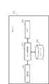
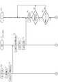
図1は、第1の実施形態における飛行システム10の構成例を示す模式図である。飛行システム10は、複数の無人航空機100、送信機50、複数の端末80、及びサーバ300を備える。無人航空機100、送信機50、端末80、及びサーバ300は、相互に有線通信又は無線通信(例えば無線LAN(Local Area Network))により通信可能である。端末80は、有線通信又は無線通信によりサーバ300と通信可能である。図1では、複数の無人航空機100として、無人航空機100A,100Bを示す。複数の端末80として、端末80A,80Bを示す。(First Embodiment)
FIG. 1 is a schematic diagram showing a configuration example of the
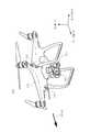
次に、無人航空機100の構成例について説明する。図2は、無人航空機100の具体的な外観の一例を示す図である。無人航空機100が移動方向STV0に飛行する時の斜視図が図2に示されている。無人航空機100は、飛行体の一例である。 Next, a configuration example of the unmanned
図2に示すように、地面と平行であって移動方向STV0に沿う方向にロール軸(x軸参照)が定義されたとする。この場合、地面と平行であってロール軸に垂直な方向にピッチ軸(y軸参照)が定められ、更に、地面に垂直であってロール軸及びピッチ軸に垂直な方向にヨー軸(z軸参照)が定められる。 As shown in FIG. 2, it is assumed that the roll axis (see x-axis) is defined in the direction parallel to the ground and along the moving direction STV0. In this case, the pitch axis (see y-axis) is defined in a direction parallel to the ground and perpendicular to the roll axis, and further, a yaw axis (z-axis) in a direction perpendicular to the ground and perpendicular to the roll axis and the pitch axis. See) is defined.
無人航空機100は、UAV本体102と、ジンバル200と、撮像装置220と、複数の撮像装置230とを含む構成である。UAV本体102は、無人航空機100の筐体の一例である。撮像装置220,230は、撮像部の一例である。 The unmanned
UAV本体102は、複数の回転翼(プロペラ)を備える。UAV本体102は、複数の回転翼の回転を制御することにより無人航空機100を飛行させる。UAV本体102は、例えば4つの回転翼を用いて無人航空機100を飛行させる。回転翼の数は、4つに限定されない。また、無人航空機100は、回転翼を有さない固定翼機でもよい。 The UAV
撮像装置220は、所望の撮像範囲に含まれる被写体(例えば、撮像対象となる上空の様子、山や川等の景色、地上の建物)を撮像する撮像用のカメラである。 The
複数の撮像装置230は、無人航空機100の飛行を制御するために無人航空機100の周囲を撮像するセンシング用のカメラである。2つの撮像装置230が、無人航空機100の機首である正面に設けられてよい。さらに、他の2つの撮像装置230が、無人航空機100の底面に設けられてよい。正面側の2つの撮像装置230はペアとなり、いわゆるステレオカメラとして機能してよい。底面側の2つの撮像装置230もペアとなり、ステレオカメラとして機能してよい。複数の撮像装置230により撮像された画像に基づいて、無人航空機100の周囲の3次元空間データが生成されてよい。なお、無人航空機100が備える撮像装置230の数は4つに限定されない。無人航空機100は、少なくとも1つの撮像装置230を備えていればよい。無人航空機100は、無人航空機100の機首、機尾、側面、底面、及び天井面のそれぞれに少なくとも1つの撮像装置230を備えてよい。撮像装置230で設定できる画角は、撮像装置220で設定できる画角より広くてよい。撮像装置230は、単焦点レンズ又は魚眼レンズを有してよい。 The plurality of
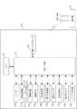
図3は、無人航空機100のハードウェア構成の一例を示すブロック図である。無人航空機100は、UAV制御部110と、通信インタフェース150と、メモリ160と、ジンバル200と、回転翼機構210と、撮像装置220と、撮像装置230と、GPS受信機240と、慣性計測装置(IMU:Inertial Measurement Unit)250と、磁気コンパス260と、気圧高度計270と、超音波センサ280と、レーザー測定器290と、を含む構成である。通信インタフェース150は、通信部の一例である。 FIG. 3 is a block diagram showing an example of the hardware configuration of the unmanned
UAV制御部110は、例えばCPU(Central Processing Unit)、MPU(Micro Processing Unit)又はDSP(Digital Signal Processor)を用いて構成される。UAV制御部110は、無人航空機100の各部の動作を統括して制御するための信号処理、他の各部との間のデータの入出力処理、データの演算処理及びデータの記憶処理を行う。 The
UAV制御部110は、メモリ160に格納されたプログラムに従って無人航空機100の飛行を制御する。UAV制御部110は、通信インタフェース150を介して遠隔の送信機50から受信した命令に従って、無人航空機100の飛行を制御する。メモリ160は無人航空機100から取り外し可能であってもよい。 The
UAV制御部110は、複数の撮像装置230により撮像された複数の画像を解析することで、無人航空機100の周囲の環境を特定してよい。UAV制御部110は、無人航空機100の周囲の環境に基づいて、例えば障害物を回避して飛行を制御する。 The
UAV制御部110は、現在の日時を示す日時情報を取得する。UAV制御部110は、GPS受信機240から現在の日時を示す日時情報を取得してよい。UAV制御部110は、無人航空機100に搭載されたタイマ(不図示)から現在の日時を示す日時情報を取得してよい。 The
UAV制御部110は、無人航空機100の位置を示す位置情報を取得する。UAV制御部110は、GPS受信機240から、無人航空機100が存在する緯度、経度及び高度を示す位置情報を取得してよい。UAV制御部110は、GPS受信機240から無人航空機100が存在する緯度及び経度を示す緯度経度情報、並びに気圧高度計270から無人航空機100が存在する高度を示す高度情報をそれぞれ位置情報として取得してよい。UAV制御部110は、超音波センサ280による超音波の放射点と超音波の反射点との距離を高度情報として取得してよい。 The
UAV制御部110は、磁気コンパス260から無人航空機100の向きを示す向き情報を取得する。向き情報には、例えば無人航空機100の機首の向きに対応する方位が示される。 The
UAV制御部110は、撮像装置220が撮像すべき撮像範囲を撮像する時に無人航空機100が存在すべき位置を示す位置情報を取得してよい。UAV制御部110は、無人航空機100が存在すべき位置を示す位置情報をメモリ160から取得してよい。UAV制御部110は、無人航空機100が存在すべき位置を示す位置情報を、通信インタフェース150を介して送信機50等の他の装置から取得してよい。UAV制御部110は、3次元地図データベースを参照して、撮像すべき撮像範囲を撮像するために、無人航空機100が存在可能な位置を特定して、その位置を無人航空機100が存在すべき位置を示す位置情報として取得してよい。 The
UAV制御部110は、撮像装置220及び撮像装置230のそれぞれの撮像範囲を示す撮像情報を取得する。UAV制御部110は、撮像範囲を特定するためのパラメータとして、撮像装置220及び撮像装置230の画角を示す画角情報を撮像装置220及び撮像装置230から取得する。UAV制御部110は、撮像範囲を特定するためのパラメータとして、撮像装置220及び撮像装置230の撮像方向を示す情報を取得する。UAV制御部110は、例えば撮像装置220の撮像方向を示す情報として、ジンバル200から撮像装置220の姿勢の状態を示す姿勢情報を取得する。UAV制御部110は、無人航空機100の向きを示す情報を取得する。撮像装置220の姿勢の状態を示す情報は、ジンバル200のピッチ軸及びヨー軸の基準回転角度からの回転角度を示す。UAV制御部110は、撮像範囲を特定するためのパラメータとして、無人航空機100が存在する位置を示す位置情報を取得する。UAV制御部110は、撮像装置220及び撮像装置230の画角及び撮像方向、並びに無人航空機100が存在する位置に基づいて、撮像装置220が撮像する地理的な範囲を示す撮像範囲を画定し、撮像範囲を示す撮像情報を生成することで、撮像情報を取得してよい。 The
UAV制御部110は、撮像装置220が撮像すべき撮像範囲を示す撮像情報を取得してよい。UAV制御部110は、メモリ160から撮像装置220が撮像すべき撮像情報を取得してよい。UAV制御部110は、通信インタフェース150を介して送信機50等の他の装置から撮像装置220が撮像すべき撮像情報を取得してよい。 The
UAV制御部110は、無人航空機100の周囲に存在するオブジェクトの立体形状(3次元形状)を示す立体情報(3次元情報)を取得してよい。オブジェクトは、例えば、建物、道路、車、木等の風景の一部である。立体情報は、例えば、3次元空間データである。UAV制御部110は、複数の撮像装置230から得られたそれぞれの画像から、無人航空機100の周囲に存在するオブジェクトの立体形状を示す立体情報を生成することで、立体情報を取得してよい。UAV制御部110は、メモリ160に格納された3次元地図データベースを参照することにより、無人航空機100の周囲に存在するオブジェクトの立体形状を示す立体情報を取得してよい。UAV制御部110は、ネットワーク上に存在するサーバが管理する3次元地図データベースを参照することで、無人航空機100の周囲に存在するオブジェクトの立体形状に関する立体情報を取得してよい。 The
UAV制御部110は、撮像装置220及び撮像装置230により撮像された画像データを取得する。 The
UAV制御部110は、ジンバル200、回転翼機構210、撮像装置220、及び撮像装置230を制御する。UAV制御部110は、撮像装置220の撮像方向又は画角を変更することによって、撮像装置220の撮像範囲を制御する。UAV制御部110は、ジンバル200の回転機構を制御することで、ジンバル200に支持されている撮像装置220の撮像範囲を制御する。 The
本明細書では、撮像範囲は、撮像装置220又は撮像装置230により撮像される地理的な範囲をいう。撮像範囲は、緯度、経度、及び高度で定義される。撮像範囲は、緯度、経度、及び高度で定義される3次元空間データにおける範囲でよい。撮像範囲は、撮像装置220又は撮像装置230の画角及び撮像方向、並びに無人航空機100が存在する位置に基づいて特定される。撮像装置220及び撮像装置230の撮像方向は、撮像装置220及び撮像装置230の撮像レンズが設けられた正面が向く方位と俯角とから定義される。撮像装置220の撮像方向は、無人航空機100の機首の方位と、ジンバル200に対する撮像装置220の姿勢の状態とから特定される方向である。撮像装置230の撮像方向は、無人航空機100の機首の方位と、撮像装置230が設けられた位置とから特定される方向である。 As used herein, the imaging range refers to the geographical range imaged by the
UAV制御部110は、回転翼機構210を制御することで、無人航空機100の飛行を制御する。つまり、UAV制御部110は、回転翼機構210を制御することにより、無人航空機100の緯度、経度、及び高度を含む位置を制御する。UAV制御部110は、無人航空機100の飛行を制御することにより、撮像装置220及び撮像装置230の撮像範囲を制御してよい。UAV制御部110は、撮像装置220が備えるズームレンズを制御することで、撮像装置220の画角を制御してよい。UAV制御部110は、撮像装置220のデジタルズーム機能を利用して、デジタルズームにより、撮像装置220の画角を制御してよい。 The
撮像装置220が無人航空機100に固定され、撮像装置220を動かせない場合、UAV制御部110は、特定の日時に特定の位置に無人航空機100を移動させることにより、所望の環境下で所望の撮像範囲を撮像装置220に撮像させることができる。あるいは撮像装置220がズーム機能を有さず、撮像装置220の画角を変更できない場合でも、UAV制御部110は、特定された日時に、特定の位置に無人航空機100を移動させることで、所望の環境下で所望の撮像範囲を撮像装置220に撮像させることができる。 When the
UAV制御部110は、無人航空機100の飛行モードを設定してよい。飛行モードは、例えば、通常飛行モード、低速飛行モード、一時停止モード、等を含む。設定された飛行モードの情報は、メモリ160に保持されてよい。通常飛行モードは、速度制限なく飛行可能な飛行モードである。低速飛行モードは、所定の速度以上の速度での飛行が禁止され、速度制限されて飛行可能な飛行モードである。一時停止モードは、無人航空機100の移動が禁止され、ホバリングが可能な飛行モードである。 The
UAV制御部110は、撮像装置220により撮像された撮像画像に対して、この撮像画像に関する情報を付加情報(メタデータの一例)として付加してよい。付加情報は、各種パラメータを含んでよい。各種パラメータは、撮像時の無人航空機100の飛行に関するパラメータ(飛行パラメータ)と撮像時の撮像装置220による撮像に関する情報(撮像パラメータ)とを含んでよい。飛行パラメータは、撮像位置情報、撮像経路情報、撮像時刻情報、その他の情報のうち少なくとも1つを含んでよい。撮像パラメータは、撮像画角情報、撮像方向情報、撮像姿勢情報、撮像範囲情報、及び被写体距離情報、のうち少なくとも1つを含んでよい。 The
撮像経路情報は、撮像画像が撮像された経路(撮像経路)を示す。撮像経路情報は、撮像時に無人航空機100が飛行した経路の情報であり、撮像位置が連続的に連なる撮像位置の集合により構成されてよい。撮像位置は、GPS受信機240により取得された位置に基づいてよい。撮像時刻情報は、撮像画像が撮像された時刻(撮像時刻)を示す。撮像時刻情報は、UAV制御部110が参照するタイマの時刻情報に基づいてよい。 The imaging path information indicates the path (imaging path) in which the captured image was captured. The imaging path information is information on the path that the unmanned
撮像画角情報は、撮像画像が撮像された際の撮像装置220の画角情報を示す。撮像方向情報は、撮像画像が撮像された際の撮像装置220の撮像方向(撮像方向)を示す。撮像姿勢情報は、撮像画像が撮像された際の撮像装置220の姿勢情報を示す。撮像範囲情報は、撮像画像が撮像された際の撮像装置220の撮像範囲を示す。被写体距離情報は、撮像装置220から被写体までの距離の情報を示す。被写体距離情報は、超音波センサ280又はレーザー測定器290による検出情報に基づいてよい。 The imaged angle of view information indicates the angle of view information of the
通信インタフェース150は、送信機50や端末80やサーバ300と通信する。通信インタフェース150は、遠隔の送信機50からUAV制御部110に対する各種の命令や情報を受信する。通信インタフェース150は、撮像画像や撮像画像に関する付加情報を、端末80に送信してよい。 The
メモリ160は、UAV制御部110がジンバル200、回転翼機構210、撮像装置220、撮像装置230、GPS受信機240、慣性計測装置250、磁気コンパス260、気圧高度計270、超音波センサ280、及びレーザー測定器290を制御するのに必要なプログラム等を格納する。メモリ160は、コンピュータ読み取り可能な記録媒体でよく、SRAM(Static Random Access Memory)、DRAM(Dynamic Random Access Memory)、EPROM(Erasable Programmable Read Only Memory)、EEPROM(Electrically Erasable Programmable Read-Only Memory)、及びUSBメモリ等のフラッシュメモリの少なくとも1つを含んでよい。メモリ160は、UAV本体102の内部に設けられてよい。UAV本体102から取り外し可能に設けられてよい。 The
ジンバル200は、少なくとも1つの軸を中心に撮像装置220を回転可能に支持する。ジンバル200は、ヨー軸、ピッチ軸、及びロール軸を中心に撮像装置220を回転可能に支持してよい。ジンバル200は、ヨー軸、ピッチ軸、及びロール軸の少なくとも1つを中心に撮像装置220を回転させることで、撮像装置220の撮像方向を変更してよい。 The
回転翼機構210は、複数の回転翼211と、複数の回転翼211を回転させる複数の駆動モータ212と、駆動モータ212を駆動するための駆動電流の電流値(実測値)を計測する電流センサ213と、を有する。駆動電流は、駆動モータ212に供給される。 The
撮像装置220は、所望の撮像範囲の被写体を撮像して撮像画像のデータを生成する。撮像装置220の撮像により得られた画像データは、撮像装置220が有するメモリ、又はメモリ160に格納される。 The
撮像装置230は、無人航空機100の周囲を撮像して撮像画像のデータを生成する。撮像装置230の画像データは、メモリ160に格納される。 The
GPS受信機240は、複数の航法衛星(つまり、GPS衛星)から発信された時刻及び各GPS衛星の位置(座標)を示す複数の信号を受信する。GPS受信機240は、受信された複数の信号に基づいて、GPS受信機240の位置(つまり、無人航空機100の位置)を算出する。GPS受信機240は、無人航空機100の位置情報をUAV制御部110に出力する。なお、GPS受信機240の位置情報の算出は、GPS受信機240の代わりにUAV制御部110により行われてよい。この場合、UAV制御部110には、GPS受信機240が受信した複数の信号に含まれる時刻及び各GPS衛星の位置を示す情報が入力される。 The
慣性計測装置250は、無人航空機100の姿勢を検出し、検出結果をUAV制御部110に出力する。慣性計測装置250は、無人航空機100の姿勢として、無人航空機100の前後、左右、及び上下の3軸方向の加速度と、ピッチ軸、ロール軸、及びヨー軸の3軸方向の角速度とを検出する。 The
磁気コンパス260は、無人航空機100の機首の方位を検出し、検出結果をUAV制御部110に出力する。 The
気圧高度計270は、無人航空機100が飛行する高度を検出し、検出結果をUAV制御部110に出力する。 The
超音波センサ280は、超音波を放射し、地面や物体により反射された超音波を検出し、検出結果をUAV制御部110に出力する。検出結果は、無人航空機100から地面までの距離つまり高度を示してよい。検出結果は、無人航空機100から物体までの距離を示してよい。 The
レーザー測定器290は、物体にレーザー光を照射し、物体で反射された反射光を受光し、反射光により無人航空機100と物体との間の距離を測定する。レーザー光による距離の測定方式は、一例として、タイムオブフライト方式でよい。 The
次に、送信機50及び端末80の構成例について説明する。図4は、送信機50が装着された端末80の外観の一例を示す斜視図である。図4では、端末80の一例として、スマートフォン80Sが示されている。送信機50に対する上下前後左右の方向は、図4に示す矢印の方向にそれぞれ従うとする。送信機50は、例えば送信機50を使用する人物(以下、「操作者」という)の両手で把持された状態で使用される。 Next, a configuration example of the
送信機50は、例えば略正方形状の底面を有し、かつ高さが底面の一辺より短い略直方体(言い換えると、略箱形)の形状をした樹脂製の筐体50Bを有する。送信機50の筐体表面の略中央には、左制御棒53Lと右制御棒53Rとが突設して配置される。 The
左制御棒53L、右制御棒53Rは、それぞれ操作者による無人航空機100の移動を遠隔で制御(例えば、無人航空機100の前後移動、左右移動、上下移動、向き変更)するための操作(移動制御操作)において使用される。図4では、左制御棒53L及び右制御棒53Rは、操作者の両手からそれぞれ外力が印加されていない初期状態の位置が示されている。左制御棒53L及び右制御棒53Rは、操作者により印加された外力が解放された後、自動的に所定位置(例えば図4に示す初期位置)に復帰する。 The
左制御棒53Lの手前側(言い換えると、操作者側)には、送信機50の電源ボタンB1が配置される。電源ボタンB1が操作者により一度押下されると、例えば送信機50に内蔵されるバッテリ(不図示)の容量の残量がバッテリ残量表示部L2において表示される。電源ボタンB1が操作者によりもう一度押下されると、例えば送信機50の電源がオンとなり、送信機50の各部に電源が供給されて使用可能となる。 The power button B1 of the
右制御棒53Rの手前側(言い換えると、操作者側)には、RTH(Return To Home)ボタンB2が配置される。RTHボタンB2が操作者により押下されると、送信機50は、無人航空機100に所定の位置に自動復帰させるための信号を送信する。これにより、送信機50は、無人航空機100を所定の位置(例えば無人航空機100が記憶している離陸位置)に自動的に帰還させることができる。RTHボタンB2は、例えば屋外での無人航空機100による撮像中に操作者が無人航空機100の機体を見失った場合、又は電波干渉や予期せぬトラブルに遭遇して操作不能になった場合等に利用可能である。 The RTH (Return To Home) button B2 is arranged on the front side (in other words, the operator side) of the
電源ボタンB1及びRTHボタンB2の手前側(言い換えると、操作者側)には、リモートステータス表示部L1及びバッテリ残量表示部L2が配置される。リモートステータス表示部L1は、例えばLED(Light Emission Diode)を用いて構成され、送信機50と無人航空機100との無線の接続状態を表示する。バッテリ残量表示部L2は、例えばLEDを用いて構成され、送信機50に内蔵されたバッテリ(不図示)の容量の残量を表示する。 A remote status display unit L1 and a battery remaining amount display unit L2 are arranged on the front side (in other words, the operator side) of the power button B1 and the RTH button B2. The remote status display unit L1 is configured by using, for example, an LED (Light Emission Diode), and displays the wireless connection status between the
左制御棒53L及び右制御棒53Rより後側であって、かつ送信機50の筐体50Bの後方側面から、2つのアンテナAN1,AN2が突設して配置される。アンテナAN1,AN2は、操作者の左制御棒53L及び右制御棒53Rの操作に基づき、送信機制御部61により生成された信号(つまり、無人航空機100の移動を制御するための信号)を無人航空機100に送信する。この信号は、送信機50により入力された操作入力信号の1つである。アンテナAN1,AN2は、例えば2kmの送受信範囲をカバーできる。また、アンテナAN1,AN2は、送信機50と無線接続中の無人航空機100が有する撮像装置220により撮像された画像、又は無人航空機100が取得した各種データが無人航空機100から送信された場合に、これらの画像又は各種データを受信できる。 Two antennas AN1 and AN2 are arranged so as to project from the rear side of the
図4では、送信機50が表示部を備えていないが、表示部を備えてもよい。 In FIG. 4, the
端末80は、ホルダHLDに載置されて取り付けられてよい。ホルダHLDは、送信機50に接合されて取り付けられてよい。これにより、端末80がホルダHLDを介して送信機50に装着される。端末80と送信機50とは、有線ケーブル(例えばUSBケーブル)を介して接続されてよい。端末80が送信機50に装着されず、端末80と送信機50がそれぞれ独立して設けられてもよい。 The terminal 80 may be mounted and mounted on the holder HLD. The holder HLD may be joined and attached to the
図5は、送信機50のハードウェア構成の一例を示すブロック図である。送信機50は、左制御棒53Lと、右制御棒53Rと、送信機制御部61と、無線通信部63と、インタフェース部65と、電源ボタンB1と、RTHボタンB2と、操作部セットOPSと、リモートステータス表示部L1と、バッテリ残量表示部L2と、表示部DPとを含む構成である。送信機50は、無人航空機100の制御を指示する操作装置の一例である。 FIG. 5 is a block diagram showing an example of the hardware configuration of the
左制御棒53Lは、例えば操作者の左手により、無人航空機100の移動を遠隔で制御するための操作に使用される。右制御棒53Rは、例えば操作者の右手により、無人航空機100の移動を遠隔で制御するための操作に使用される。無人航空機100の移動は、例えば前進する方向の移動、後進する方向の移動、左方向の移動、右方向の移動、上昇する方向の移動、下降する方向の移動、左方向に無人航空機100を回転する移動、右方向に無人航空機100を回転する移動のうちいずれか又はこれらの組み合わせであり、以下同様である。 The
電源ボタンB1は一度押下されると、一度押下された旨の信号が送信機制御部61に入力される。送信機制御部61は、この信号に従い、送信機50に内蔵されるバッテリ(不図示)の容量の残量をバッテリ残量表示部L2に表示する。これにより、操作者は、送信機50に内蔵されるバッテリの容量の残量を簡単に確認できる。また、電源ボタンB1は二度押下されると、二度押下された旨の信号が送信機制御部61に渡される。送信機制御部61は、この信号に従い、送信機50に内蔵されるバッテリ(不図示)に対し、送信機50内の各部への電源供給を指示する。これにより、操作者は、送信機50の電源がオンとなり、送信機50の使用を簡単に開始できる。 When the power button B1 is pressed once, a signal to the effect that it is pressed once is input to the
RTHボタンB2は押下されると、押下された旨の信号が送信機制御部61に入力される。送信機制御部61は、この信号に従い、無人航空機100に所定の位置(例えば無人航空機100の離陸位置)に自動復帰させるための信号を生成し、無線通信部63及びアンテナAN1,AN2を介して無人航空機100に送信する。これにより、操作者は、送信機50に対する簡単な操作により、無人航空機100を所定の位置に自動で復帰(帰還)させることができる。 When the RTH button B2 is pressed, a signal to that effect is input to the
操作部セットOPSは、複数の操作部OP(例えば操作部OP1,…,操作部OPn)(n:2以上の整数)を用いて構成される。操作部セットOPSは、図3に示す左制御棒53L、右制御棒53R、電源ボタンB1及びRTHボタンB2を除く他の操作部(例えば、送信機50による無人航空機100の遠隔制御を支援するための各種の操作部)により構成される。ここでいう各種の操作部とは、例えば、無人航空機100の撮像装置220を用いた静止画の撮像を指示するボタン、無人航空機100の撮像装置220を用いた動画の録画の開始及び終了を指示するボタン、無人航空機100のジンバル200(図2参照)のチルト方向の傾きを調整するダイヤル、無人航空機100のフライトモードを切り替えるボタン、無人航空機100の撮像装置220の設定を行うダイヤルが該当する。 The operation unit set OPS is configured by using a plurality of operation unit OPs (for example, operation unit OP1, ..., Operation unit OPn) (n: an integer of 2 or more). The operation unit set OPS is for supporting remote control of the unmanned
リモートステータス表示部L1及びバッテリ残量表示部L2は、図4を参照して説明したので、ここでは説明を省略する。 Since the remote status display unit L1 and the battery remaining amount display unit L2 have been described with reference to FIG. 4, the description thereof will be omitted here.
送信機制御部61は、プロセッサ(例えばCPU、MPU又はDSP)を用いて構成される。送信機制御部61は、送信機50の各部の動作を統括して制御するための信号処理、他の各部との間のデータの入出力処理、データの演算処理及びデータの記憶処理を行う。送信機制御部61は、処理部の一例である。 The
送信機制御部61は、無人航空機100の撮像装置220が撮像した撮像画像のデータを、無線通信部63を介して取得してメモリ(不図示)に保存し、インタフェース部65を介して端末80に出力してよい。言い換えると、送信機制御部61は、無人航空機100の撮像装置220により撮像された撮像画像のデータを端末80に表示させてよい。これにより、無人航空機100の撮像装置220により撮像された撮像画像は、端末80において表示可能となる。 The
送信機制御部61は、操作者の左制御棒53L及び右制御棒53Rの操作により、その操作により指定された無人航空機100の飛行を制御するための指示信号を生成してよい。送信機制御部61は、この指示信号を、無線通信部63及びアンテナAN1,AN2を介して、無人航空機100に送信して無人航空機100を遠隔制御してよい。これにより、送信機50は、無人航空機100の移動を遠隔で制御できる。 The
無線通信部63は、2つのアンテナAN1,AN2と接続される。無線通信部63は、2つのアンテナAN1,AN2を介して、無人航空機100との間で所定の無線通信方式(例えば無線LAN)を用いた情報やデータの送受信を行う。 The
インタフェース部65は、送信機50と端末80との間の情報やデータの入出力を行う。インタフェース部65は、例えば送信機50に設けられたUSBポート(不図示)でよい。インタフェース部65は、USBポート以外のインタフェースでもよい。 The
図6Aは、端末80のハードウェア構成の一例を示すブロック図である。端末80は、端末制御部81、インタフェース部82、操作部83、通信部85、メモリ87、表示部88、撮像部89を備えてよい。表示部88は、提示部の一例である。 FIG. 6A is a block diagram showing an example of the hardware configuration of the terminal 80. The terminal 80 may include a
端末制御部81は、例えばCPU、MPU又はDSPを用いて構成される。端末制御部81は、端末80の各部の動作を統括して制御するための信号処理、他の各部との間のデータの入出力処理、データの演算処理及びデータの記憶処理を行う。 The
端末制御部81は、通信部85を介して、無人航空機100からのデータや情報を取得してよい。例えば、端末制御部81は、通信部85を介して、無人航空機100からの撮像画像やその付加情報を取得してよい。端末制御部81は、インタフェース部82を介して、送信機50からのデータや情報を取得してよい。端末制御部81は、操作部83を介して入力されたデータや情報を取得してよい。端末制御部81は、メモリ87に保持されたデータや情報を取得してよい。端末制御部81は、データや情報を表示部88に送り、このデータや情報に基づく表示情報を表示部88に表示させてよい。 The
端末制御部81は、通信部85を介して、無人航空機100の位置情報を、無人航空機100から直接取得したり、付加情報に含まれる撮像位置情報として取得したりしてよい。端末制御部81は、無人航空機100の位置情報を逐次取得し、位置情報に基づいて、無人航空機100が移動する速度や移動する方向の情報を算出してよい。無人航空機100の位置や速度や移動方向の情報は、付加情報に含められて、サーバ300等に通知されてよい。 The
端末制御部81は、無人航空機100の制御を指示するためのアプリケーションを実行してよい。端末制御部81は、アプリケーションで用いられる各種のデータを生成してよい。 The
端末制御部81は、無人航空機100からの撮像画像を取得してよい。端末制御部81は、無人航空機100からの撮像画像を表示部88に表示させてよい。 The
端末制御部81は、撮像部89により撮像されたユーザの目の周辺部が映り込んだ画像(ユーザ画像)を取得してよい。ユーザ画像は、無人航空機100からの撮像画像が表示された表示部88を、ユーザが見ている際に撮像された画像でよい。端末制御部81は、撮像画像に対して画像認識(例えばセグメンテーション処理、物体認識処理)を行うことで、ユーザの目(例えば瞳孔)を検出する。 The
端末制御部81は、端末80を操作するユーザが表示部88に表示された撮像画像において注目している注目点を検出してよい。この場合、端末制御部81は、公知の視線検出技術を用いて、撮像画像が表示された表示部88においてユーザが視ている(注目している)画面上の位置(視線検知位置)、つまり注目点の座標を取得してよい。つまり、端末制御部81は、ユーザの目が表示部88に表示された撮像画像のどの位置を見ているかを認識してよい。 The
端末制御部81は、無人航空機100からの撮像画像に関する付加情報に含まれる撮像範囲情報を取得してよい。つまり、端末制御部81は、無人航空機100からの撮像範囲情報により、地理的な撮像範囲が地図上での範囲として特定可能である。端末制御部81は、注目点の座標が、表示部88に表示された撮像画像のどの位置であるかを検出し、撮像画像の範囲が示す地理的な撮像範囲のどの位置に対応するかを検出してよい。これにより、注目点として、地理的な撮像範囲に含まれる特定の位置が検出され得る。 The
端末制御部81は、通信部85を介して外部の地図データベースを有する地図サーバと通信し、注目点に対応する地理的な特定の位置に、地図上でどのようなオブジェクトが存在するかを検出してよい。これにより、注目点として、地理的な撮像範囲に含まれる特定のオブジェクトが検出されてよい。なお、メモリ87が、地図サーバが有する地図データベースを有していてもよい。 The
端末制御部81は、無人航空機100からの撮像画像に対して画像認識(例えばセグメンテーション処理、物体認識処理)を行うことで、撮像画像中の各オブジェクトを認識してよい。この場合、例えば地図データベースの情報が古い場合でも、撮像時の撮像画像に映り込んだオブジェクトを認識できる。 The
注目点の情報としては、位置情報(緯度及び経度、又は、緯度、経度及び高度)であってもよいし、○○タワー等の固有名称で識別されるオブジェクトの情報であってもよい。また、オブジェクトの情報は、例えば○○タワー等の固有名称の他、オブジェクトの情報や位置情報を含んでよい。なお、この注目点検出の方法は、一例であり、他の方法で注目点が検出されてもよい。 The information of the point of interest may be position information (latitude and longitude, or latitude, longitude and altitude), or may be information on an object identified by a unique name such as a XX tower. Further, the object information may include object information and position information in addition to a unique name such as XX tower. Note that this method of detecting a point of interest is an example, and the point of interest may be detected by another method.
インタフェース部82は、送信機50と端末80との間の情報やデータの入出力を行う。インタフェース部82は、例えば端末80に設けられたUSBコネクタ(不図示)でよい。インタフェース部82は、USBコネクタ以外のインタフェースでもよい。 The
操作部83は、端末80の操作者により入力されるデータや情報を受け付ける。操作部83は、ボタン、キー、タッチパネル、マイクロホン、等を含んでよい。ここでは、主に、操作部83と表示部88とがタッチパネルにより構成されることを例示する。この場合、操作部83は、タッチ操作、タップ操作、ドラック操作等を受付可能である。 The
通信部85は、各種の無線通信方式により無人航空機100との間で通信する。無線通信方式は、例えば、無線LAN、Bluetooth(登録商標)、近距離無線通信、又は公衆無線回線を介した通信を含んでよい。また、通信部85は、有線通信してもよい。 The
メモリ87は、例えば端末80の動作を規定するプログラムや設定値のデータが格納されたROMと、端末制御部81の処理時に使用される各種の情報やデータを一時的に保存するRAMを有してよい。メモリ87は、ROM及びRAM以外のメモリが含まれてよい。メモリ87は、端末80の内部に設けられてよい。メモリ87は、端末80から取り外し可能に設けられてよい。プログラムは、アプリケーションプログラムを含んでよい。 The
表示部88は、例えばLCD(Liquid Crystal Display)を用いて構成され、端末制御部81から出力された各種の情報やデータを表示する。表示部88は、無人航空機100の撮像装置220により撮像された撮像画像のデータを表示してよい。 The
撮像部89は、イメージセンサを含み、画像を撮像する。撮像部89は、表示部88が備えられた正面側に設けられてよい。撮像部89は、表示部88により表示された画像を見ているユーザの目の周辺を含めて被写体とし、画像(ユーザ画像)を撮像してよい。撮像部89は、ユーザ画像を端末制御部81へ出力してよい。撮像部89は、ユーザ画像以外の画像を撮像してもよい。 The
図6Bは、サーバ300のハードウェア構成を示すブロック図である。サーバ300は、情報処理装置の一例である。サーバ300は、サーバ制御部310、通信部320、メモリ340、及びストレージ330を有する。 FIG. 6B is a block diagram showing a hardware configuration of the
サーバ制御部310は、例えばCPU、MPU又はDSPを用いて構成される。サーバ制御部310は、サーバ300の各部の動作を統括して制御するための信号処理、他の各部との間のデータの入出力処理、データの演算処理及びデータの記憶処理を行う。 The
サーバ制御部310は、通信部320を介して、無人航空機100からのデータや情報を取得してよい。サーバ制御部310は、通信部320を介して、端末80からのデータや情報を取得してよい。サーバ制御部310は、無人航空機100の制御を指示するためのアプリケーションを実行してよい。サーバ制御部310は、アプリケーションで用いられる各種のデータを生成してよい。 The
サーバ制御部310は、無人航空機100の衝突回避のための情報提示指示に関する処理を行う。サーバ制御部310は、無人航空機100により撮像された画像におけるユーザの注目点に基づいて、情報を提示させる。 The
サーバ制御部310は、通信部320を介して、各無人航空機100の位置情報を、無人航空機100から直接取得したり、各端末80から付加情報に含まれる撮像位置情報として取得したりしてよい。サーバ制御部310は、無人航空機100の位置情報を逐次取得し、位置情報に基づいて、無人航空機100が移動する速度や移動する方向の情報を算出してよい。サーバ制御部310は、通信部320を介して、各端末80から、付加情報に含められた無人航空機100の位置や速度や移動方向の情報を取得してもよい。 The
メモリ340は、例えばサーバ300の動作を規定するプログラムや設定値のデータが格納されたROMと、サーバ制御部310の処理時に使用される各種の情報やデータを一時的に保存するRAMを有してよい。メモリ340は、ROM及びRAM以外のメモリが含まれてよい。メモリ340は、サーバ300の内部に設けられてよい。メモリ340は、サーバ300から取り外し可能に設けられてよい。プログラムは、アプリケーションプログラムを含んでよい。 The
通信部320は、有線または無線により、他の装置(例えば送信機50、端末80、無人航空機100)と通信可能である。ストレージ330は、撮像画像、マップ情報等を記憶可能な大容量の記録媒体である。 The
(第1の実施形態の第1動作例)
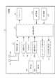
図7は、第1動作例におけるサーバ300による情報提示指示手順を示すシーケンス図である。本実施形態では、送信機50及び端末80を用いて無人航空機100をFPV飛行させることを想定する。FPV飛行では、送信機50及び端末80の操作者は、無人航空機100を目視することなく、例えば端末80の表示部88に表示された無人航空機100の撮像画像を見ながら、無人航空機100を操縦する。(First operation example of the first embodiment)
FIG. 7 is a sequence diagram showing an information presentation instruction procedure by the
ここでは、複数のユーザが、無人航空機100Aの飛行の制御を指示する送信機50や端末80を操作することを想定する。例えば、ユーザUa(ユーザU1)が、無人航空機100Aの飛行の制御を指示する送信機50や端末80を操作する。ユーザUb(ユーザU2)が、他の無人航空機100Bの飛行の制御を指示する送信機50や端末80を操作する。 Here, it is assumed that a plurality of users operate the
なお、ユーザAが操作する送信機50や端末80や無人航空機100の各部については、符号の末尾に「A」を付して示すこともある(例えば、端末80A、表示部88A、無人航空機100A)。ユーザBが操作する送信機50や端末80の各部については、符号の末尾に「B」を付して示すこともある(例えば、端末80B、表示部88B、無人航空機100B)。なお、無人航空機100B、端末80B、ユーザUbは、複数存在してもよい。 The
飛行中、無人航空機100(例えば無人航空機100A)では、撮像装置220は、繰り返し撮像する(T1)。UAV制御部110は、撮像装置220による撮像画像をメモリ160に記録し、撮像画像に関する付加情報もメモリ160に記録してよい。UAV制御部110は、メモリ160に記憶された撮像画像及びその付加情報を、通信インタフェース150を介して、端末80に送信する(T2)。 During flight, in an unmanned aerial vehicle 100 (eg, unmanned
端末80(例えば端末80A)では、端末制御部81は、通信部85を介して、無人航空機100Aから送信された撮像画像及びその付加情報を受信する(T3)。端末制御部81は、表示部88に撮像画像を表示させる。端末制御部81は、端末80を操作するユーザが表示部88に表示された撮像画像において注目している注目点を検出する(T4)。 In the terminal 80 (for example, the terminal 80A), the
図8は、注目点の検出例を示す図である。この例では、表示部88には、撮像装置220による撮像画像GZ1が表示されている。端末制御部81は、表示部88に表示された撮像画像GZ1に対し、視線検出によりタワーJ1がユーザの視線位置であると判断し、注目点tp1を検出する。 FIG. 8 is a diagram showing an example of detecting a point of interest. In this example, the
図7に戻り、端末制御部81は、通信部85を介して、注目点の情報をサーバ300に送信する(T5)。なお、端末制御部81は、通信部85を介して、注目点の情報の他、端末80が無人航空機100から取得した付加情報の少なくとも一部を送信してもよい。 Returning to FIG. 7, the
サーバ300では、サーバ制御部310は、通信部320を介して、端末80から送信された情報(例えば注目点の情報)を受信し、ストレージ330に記憶する(T6)。サーバ300は、無人航空機100Aの他、他の無人航空機100Bからも同様に情報(例えば注目点の情報)を受信し、ストレージ330に記憶する。 In the
サーバ制御部310は、ストレージ330に記憶された1つ以上の注目点の情報のうち、注目点が示す位置情報やオブジェクトが同じである(共通する)複数の注目点の情報が存在するか否かを判別する(T7)。なお、共通する注目点を、位置情報やオブジェクトが共通する注目点を、共通注目点とも称する。 Among the information of one or more points of interest stored in the
図9Aは、2人のユーザ(操作者)による注目点が共通している場合の各表示部88に表示された撮像画像GZ1,GZ2を示す図である。2人のユーザは、ユーザU1,U2でよい。 FIG. 9A is a diagram showing captured images GZ1 and GZ2 displayed on each
撮像画像GZ1,GZ2は、無人航空機100A,100Bの撮像装置220による撮像方向の異なる画像であり、それぞれタワーJ1,橋J2,ビルJ3を含む。図9Aでは、注目点tp1,tp2は、タワーJ1であり、共通しているので、共通注目点である。 The captured images GZ1 and GZ2 are images having different imaging directions by the
図9Bは、2人のユーザによる注目点が共通していない場合の各端末の表示部88A,88Bにそれぞれ表示された撮像画像GZ1,GZ2を示す図である。図9Bでは、撮像画像GZ1に対する注目点tp1は、タワーJ1である。一方、撮像画像GZ2に対する注目点tp2は、橋である。したがって、注目点tp1,tp2は、共通注目点ではない。 FIG. 9B is a diagram showing captured images GZ1 and GZ2 displayed on the
なお、注目点の情報がタワー等のオブジェクトの情報でなく、地理的な位置情報である場合、例えば2つの注目点の間の距離が閾値未満である場合に、共通注目点であると判定されてもよい。 In addition, when the information of the attention point is not the information of the object such as the tower but the geographical position information, for example, when the distance between the two attention points is less than the threshold value, it is determined to be the common attention point. You may.
共通する複数の注目点の情報が存在しない場合、つまり共通注目点が存在しない場合、サーバ制御部310は、図7において最初の手順T6に戻る。 When there is no information on a plurality of common points of interest, that is, when there is no common point of interest, the
一方、手順T7において、共通する複数の注目点の情報が存在する場合、サーバ制御部310は、通信部320を介して、共通する注目点の情報を送信した端末80Aに対し、端末80Aが飛行の制御を指示する無人航空機100Aとは異なる他の無人航空機100Bの情報を、送信する(T8)。同様に、手順T8において、サーバ制御部310は、通信部320を介して、共通する注目点の情報を送信した端末80Bに、端末80Bが飛行の制御を指示する無人航空機100Bとは異なる無人航空機100Aの情報を、送信する。 On the other hand, in the procedure T7, when there is information on a plurality of common points of interest, the
ここでの他の無人航空機100Bの情報は、例えば、他の無人航空機100Bが存在することを示す情報、他の無人航空機100Bの位置情報、他の無人航空機100Bが移動する移動方向の情報、等を含んでよい。同様に、ここでの無人航空機100Aの情報は、例えば、無人航空機100Aが存在することを示す情報、無人航空機100Aの位置情報、無人航空機100Aが移動する移動方向の情報、等を含んでよい。 The information of the other unmanned
端末80Aでは、端末制御部81は、通信部85を介して、他の無人航空機100Bの情報を受信する(T9)。同様に、他の端末80Bでは、端末制御部81は、無人航空機100Aの情報を受信する(T9)。端末80Aの端末制御部81は、受信された無人航空機100Bの情報を基に、表示部88に表示された撮像画像GZ1に対し、重畳画像を表示部88に表示させる(T10)。 In the terminal 80A, the
重畳画像としては、矢印を模したマークmk1が、撮像画像CZ1に重畳されて表示されてよい。また、端末80Aの端末制御部81は、表示部88に表示された撮像画像GZ1に対し、重畳画像であるマークmk1を表示させる他、他の無人航空機100Bの情報を表示させてもよい。例えば、端末制御部81は、他の無人航空機の存在の有無、他の無人航空機の位置、速度、移動方向等を表示させてもよい。 As the superimposed image, the mark mk1 imitating an arrow may be superimposed and displayed on the captured image CZ1. Further, the
なお、ここでは、他の無人航空機100Bの情報を表示することを例示したが、他の無人航空機100Bの情報が表示以外の方法で提示されてもよい。例えば、端末80がスピーカを備え、他の無人航空機100Bの情報を音声出力してよい。例えば、端末80がバイブレータを備え、他の無人航空機100Bの情報を振動により示してもよい。 Although the display of the information of the other unmanned
図7の処理によれば、サーバ300は、各端末80から注目点の情報を取得し、取得された複数の注目点に共通注目点が存在するか否かを判別する。注目点は、ユーザが注目している位置やオブジェクトであり、注目点に向かって無人航空機100を飛行させようとしている可能性が高い。そのため、注目点が共通する共通注目点である場合、注目点に対応する地理的な位置に近づくにつれて無人航空機100同士が衝突する可能性が高くなる。このような場合であっても、各端末80のユーザは、他のユーザが操縦する他の無人航空機100に関する情報を、FPV飛行において確認している自機において提示できる。よって、各端末80のユーザは、他のユーザも同じ注目点に注目していることを認識でき、安全性を向上させて無人航空機100を操縦できる。 According to the process of FIG. 7, the
なお、T6とT7との間において、サーバ制御部310は、注目点が受信された無人航空機100A,100Bが移動しているか否かを判定してもよい。この場合、サーバ制御部310は、通信部320を介して、注目点の情報を取得するとともに、無人航空機100A,100Bの時系列の位置情報を取得してよい。この位置情報は、通信部320を介して、端末80A,80Bから順次、撮像画像の付加情報に撮像位置情報として含まれて取得されてもよいし、無人航空機100A,100Bから順次、直接取得されてもよい。そして、サーバ制御部310は、無人航空機100A,100Bの少なくとも一方が移動している場合に、共通注目点に基づく情報提示を指示してよく、無人航空機100A,100Bの双方が移動していない場合に、共通注目点に基づく情報提示を指示しなくてよい。 In addition, between T6 and T7, the
つまり、サーバ300は、無人航空機100A,100Bが移動しており共通の位置やオブジェクトに注目している場合には、衝突する可能性が高くなるので、情報提示を指示してよい。サーバ300は、無人航空機100A,100Bが共に移動していない場合、共通の位置やオブジェクトに注目している場合でも、例えば無人航空機100A,100Bが衝突する可能性が低いので、情報提示を指示しなくてよい。 That is, when the unmanned
このように、サーバ制御部310は、無人航空機100Aが移動しているか否かを判定してよい。サーバ制御部310は、無人航空機100Aが移動している場合、端末80Aに、無人航空機100Bに関する情報を表示させてよい。 In this way, the
無人航空機100Aが移動している場合、他の無人航空機100Bと衝突する可能性が高くなる。この場合でも、サーバ300は、他の無人航空機100Bの情報を警告情報として通知でき、無人航空機100Aと無人航空機100Bとの衝突の発生を抑制できる。 When the unmanned
また、サーバ300では、サーバ制御部310は、取得された無人航空機100A,100Bの位置情報を基に、無人航空機100Aから無人航空機100Bまでの距離r1を算出してよい。距離r1が閾値以下である場合に、サーバ制御部310が、端末80Aに、無人航空機100Bに関する情報、例えば無人航空機100Bが存在していることを表すマークを表示させてよい。ここでの閾値は、後述する第2の動作例で用いる閾値Dist1と同値でもよい。 Further, in the
これにより、複数の無人航空機100が互いに近くを飛行し、複数の無人航空機100が衝突する可能性が高くなる場合でも、無人航空機100Aの飛行の制御を指示するユーザU1は、他の無人航空機100Bの存在を知ることができる。よって、サーバ300は、無人航空機100Aと無人航空機100Bとの衝突の発生を抑制できる。 As a result, even when a plurality of unmanned
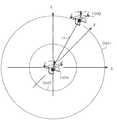
図10は、2つの無人航空機100A,100Bの位置関係を示す図である。無人航空機100Aを原点とする3次元座標を設定するとする。この場合、図10では、無人航空機100Bは、プラスx方向およびプラスy方向に位置し、かつ、プラスz方向に(つまり無人航空機100Aよりも上空に)位置する。 FIG. 10 is a diagram showing the positional relationship between the two unmanned
図11Aは、端末80Aの表示部88Aに表示された無人航空機100Aの撮像画像GZ1を示す図である。図11Aでは、無人航空機100A,100Bの位置関係が、図10の位置関係であることを想定している。 FIG. 11A is a diagram showing a captured image GZ1 of the unmanned
端末80Aの端末制御部81Aは、サーバ300からの情報の表示の指示を受けて(図7のT8参照)、表示部88Aを介して各種情報を表示する。図11Aでは、表示部88Aの右上端部には、右から左に向かう矢印を模したマークmk1が撮像画像GZ1に重畳して表示される。このマークmk1は、図10に示したように、表示部88Aでは死角となっている右上方向に別の無人航空機100Bが存在して飛行していることを表す。したがって、マークmk1で示す方向に、無人航空機100Aによる撮像方向をずらすと、撮像画像GZ1には別の無人航空機100Bが現れる。 The terminal control unit 81A of the terminal 80A receives an instruction to display information from the server 300 (see T8 in FIG. 7), and displays various information via the
この場合、サーバ300のサーバ制御部310は、通信部320を介して無人航空機100Aの位置情報を取得してよい。サーバ制御部310は、通信部320を介して無人航空機100Bの位置情報を取得してよい。この位置情報は、通信部320を介して、端末80A,80Bから順次、撮像画像の付加情報に撮像位置情報として含まれて取得されてもよいし、無人航空機100A,100Bから順次、直接取得されてもよい。サーバ制御部310は、無人航空機100A,100Bの位置情報を基に、無人航空機100A,100Bの位置関係を考慮して、マークmk1が表示される位置を決定してよい。サーバ制御部310は、通信部320を介して、マークmk1が表示される位置の情報を含めて、無人航空機100Bに関する情報(例えば無人航空機100Bが存在することを示す情報)を表示するよう、端末80Aへ指示してよい。 In this case, the
なお、マークmk1は、無人航空機100Bの移動方向を示してもよい。つまり、表示部88Aに表示された撮像画像に対応する地理的な範囲や向きにおいて、右から左に無人航空機100Bが飛行していることを示してよい。また、マークmk1以外の情報により、無人航空機100Bの位置や速度等の無人航空機100Bに関する情報が表示されてもよい。 The mark mk1 may indicate the moving direction of the unmanned
図11Bは、他の端末80Bの表示部88Bに表示された無人航空機100Bの撮像画像GZ2を示す図である。図11Bでは、無人航空機100A,100Bの位置関係が、図10の位置関係であることを想定している。 FIG. 11B is a diagram showing a captured image GZ2 of the unmanned
表示部88Bの左下端部には、左から右に向かう矢印を模したマークmk2が撮像画像GZ2に重畳して表示される。このマークmk2は、図10に示したように、表示部88Bでは死角となっている左方向に別の無人航空機100Aが存在して飛行していることを表す。したがって、マークmk2で示す方向に、無人航空機100Bによる撮像方向をずらすと、撮像画像GZ2には別の無人航空機100Aが現れる。 At the lower left end of the
この場合、サーバ300のサーバ制御部310は、通信部320を介して無人航空機100Aの位置情報を取得してよい。サーバ制御部310は、通信部320を介して無人航空機100Bの位置情報を取得してよい。この位置情報は、通信部320を介して、端末80A,80Bから順次、撮像画像の付加情報に撮像位置情報として含まれて取得されてもよいし、無人航空機100A,100Bから順次、直接取得されてもよい。サーバ制御部310は、無人航空機100A,100Bの位置情報を基に、無人航空機100A,100Bの位置関係を考慮して、マークmk2が表示される位置を決定してよい。サーバ制御部310は、通信部320を介して、マークmk2が表示される位置の情報を含めて、無人航空機100Aに関する情報(例えば無人航空機100Aが存在することを示す情報)を表示するよう、端末80Bへ指示してよい。 In this case, the
なお、マークmk2は、無人航空機100Aの移動方向を示してもよい。つまり、表示部88Bに表示された撮像画像に対応する地理的な範囲や向きにおいて、左から右に無人航空機100Aが飛行していることを示してよい。また、マークmk2以外の情報により、無人航空機100Aの位置や速度等の無人航空機100Aに関する情報が表示されてもよい。 The mark mk2 may indicate the moving direction of the unmanned
このように、サーバ300のサーバ制御部310は、無人航空機100A及び無人航空機100Bの位置情報を取得してよい。サーバ制御部310は、無人航空機100Aに対する無人航空機100Bの位置に基づく位置に、表示部88Aに無人航空機100Bの存在を示す情報を表示するよう指示してよい。 In this way, the
これにより、端末80Aは、サーバ300からの指示を受けて、無人航空機100Aの位置に対する無人航空機100Bの位置に基づく位置に、例えば、表示部88の画面右上端部に、無人航空機100Bの存在を表すマークmk2(存在情報の一例)を表示できる。端末80Aを操作するユーザU1は、無人航空機100Bの存在位置を直感的に把握し易くなる。よって、ユーザU1は、無人航空機100Bの位置を加味して端末80Aを操作し易くなる。したがって、サーバ300は、無人航空機100Aと無人航空機100Bとの衝突の発生を抑制できる。 As a result, the
このように、第1動作例では、共通注目点に注目するユーザに対応する無人航空機100A(自機)と他の無人航空機100Bが存在する場合、端末80Aの表示部88Aに表示された撮像画像に、他の無人航空機100Bが現れていなくても、他の無人航空機100Bを表すマークmk1が表示される。 As described above, in the first operation example, when the unmanned
また、サーバ制御部310は、無人航空機100Aの飛行の制御を指示する端末80Aを操作するユーザU1が、端末80Aに表示された、無人航空機100Aによる撮像画像GZ1において注目する注目点tp1を取得する。サーバ制御部310は、無人航空機100Bの飛行の制御を指示する端末80Bを操作するユーザU2が、端末80Bに表示された、無人航空機100Bによる撮像画像GZ2において注目する注目点tp2を取得する。サーバ制御部310は、注目点tp1と注目点tp2が、同じ注目点を示す共通注目点であるか否かを判定する。サーバ制御部310は、これらが共通注目点である場合、サーバ制御部310は、端末80Aに、無人航空機100Bの存在や接近を表すマークmk1を表示させる。 Further, the
サーバ制御部310は、処理部の一例である。無人航空機100Aは、第1の飛行体の一例である。端末80Aは、第1の端末の一例である。撮像画像GZ1は、第1の画像の一例である。注目点tp1は、第1の注目点の一例である。無人航空機100Bは、第2の飛行体の一例である。端末80Bは、第2の端末の一例である。撮像画像GZ2は、第2の画像の一例である。注目点tp2は、第2の注目点の一例である。 The
これにより、ユーザU1は、無人航空機100Aの周囲に存在する無人航空機100Bに関する情報を把握できる。したがって、無人航空機100AがFPV飛行する場合に、無人航空機100Aの周囲の状況確認が困難であり、複数の無人航空機100の目的地が共通する注目点に対応する同じ目的地であっても、ユーザU1は、無人航空機100Bに関する情報を加味して端末80Aを操作できる。したがって、サーバ300は、無人航空機100Aと無人航空機100Bとの衝突の発生を抑制できる。 As a result, the user U1 can grasp the information about the unmanned
(第1の実施形態の第2動作例)
第1動作例では、注目点が共通する他の無人航空機の存在を表すマークを、端末のディスプレイに撮像画像に重ねて表示する場合を示した。第2動作例では、共通する注目点が同じである、他の無人航空機との間の距離が閾値未満となった場合、この無人航空機の飛行の制御を指示する端末に推奨情報を表示する場合を示す。(Second operation example of the first embodiment)
In the first operation example, a case where a mark indicating the existence of another unmanned aerial vehicle having a common point of interest is displayed on the display of the terminal overlaid on the captured image is shown. In the second operation example, when the distance to another unmanned aerial vehicle having the same common point of interest is less than the threshold value, the recommended information is displayed on the terminal instructing the flight control of this unmanned aerial vehicle. Is shown.
図12A及び図12Bは、第2動作例におけるサーバ300による無人航空機視点での情報提示指示手順を示すシーケンス図である。図7に示した第1動作例と同一の手順については、同一の符号を用いることで、その説明を省略又は簡略化する。 12A and 12B are sequence diagrams showing an information presentation instruction procedure from the viewpoint of an unmanned aerial vehicle by the
まず、飛行システム10は、T1〜T6の処理を行う。 First, the
手順T7において、注目点が共通する複数の無人航空機100が存在する場合、サーバ300のサーバ制御部310は、無人航空機100Aから他の無人航空機100Bまでの距離r1が、閾値Dist1以下であるか否かを判別する(T8A)。 In the procedure T7, when there are a plurality of unmanned
図13は、2つの無人航空機100A,100Bの間の距離r1に対して設定された閾値Dist1,Dist2の空間を示す図である。 FIG. 13 is a diagram showing the space of the threshold values Dist1 and Dist2 set for the distance r1 between the two unmanned
2つの無人航空機100A,100Bの間の距離r1は、無人航空機100Aの位置を原点とした場合、無人航空機100Bの位置座標(x,y,z)を用いて、式(1)で表される。
r1 = (x2 + y2 + z2)1/2 ……(1)The distance r1 between the two unmanned
r1 = (x2 + y2 + z2)1/2 …… (1)
他の無人航空機100Bまでの距離r1と比較される閾値Dist1は、他の無人航空機100Bと接近が予想されるとして、速度の低下を推奨するための値である。他の無人航空機100Bまでの距離r1と比較される閾値Dist2は、他の無人航空機100Bと衝突が予想されるとして、ホバリング等の一時停止を推奨するための値である。したがって、閾値Dist2は、閾値Dist1より小さな値である。 The threshold value Dist1 to be compared with the distance r1 to the other unmanned
距離r1が閾値Dist1以下でない場合、つまり距離r1が閾値Dist1よりも大きい場合、サーバ300のサーバ制御部310は、図12AのT8Aにおいてサーバ300の最初の手順T6に戻る。 If the distance r1 is not less than or equal to the threshold Dist1, that is, if the distance r1 is greater than the threshold Dist1, the
一方、距離r1が閾値Dist1以下である場合、図12Bに進み、サーバ制御部310は、無人航空機100Bまでの距離r1が閾値Dist2以下であるか否かを判別する(T9A)。 On the other hand, when the distance r1 is the threshold value Dist1 or less, the process proceeds to FIG. 12B, and the
距離r1が閾値Dist2以下でない場合、つまり距離r1が閾値Dist1よりも大きい場合、サーバ制御部310は、低速飛行モードを推奨し、低速飛行モードを推奨するための推奨情報を生成する(T10A)。一方、手順T9Aで距離r1が閾値Dist2以下である場合、サーバ制御部310は、ホバリング等が可能な一時停止(一時停止モード)を推奨し、一時停止を推奨するための推奨情報を生成する(T11A)。 When the distance r1 is not equal to or less than the threshold value Dist2, that is, when the distance r1 is larger than the threshold value Dist1, the
サーバ制御部310は、手順T10A又は手順T11Aの推奨情報を、通信部320を介して無人航空機100Aの飛行の制御を指示する端末80Aに送信する(T12A)。 The
端末80Aの端末制御部81は、通信部85を介して、サーバ300から推奨情報を受信する(T13A)。端末制御部81は、推奨情報に従って、表示部88に推奨情報を含む推奨画面を表示する(T14A)。 The
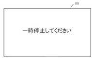
図14Aは、距離r1が閾値Dist1以内である場合に表示部88に表示される推奨画面GM1を示す図である。推奨画面GM1では、例えば、「低速飛行モードにしてください」のメッセージが表示される。図14Bは、距離r1が閾値Dist2以内である場合に表示部88に表示される推奨画面GM2を示す図である。推奨画面GM2では、「一時停止してください」のメッセージが表示される。図14A,図14Bに示すメッセージは、推奨画面GM1,GM2において単独で表示される。なお、これらのメッセージは、撮像画像に重畳して表示されてもよいし、第1動作例で示したマークと共に撮像画像に重畳して表示されてもよい。 FIG. 14A is a diagram showing a recommended screen GM1 displayed on the
図12A及び図12Bに示した処理によれば、サーバ300は、無人航空機100同士がある程度接近すると、無人航空機100に飛行の制御を指示する端末80に対して、飛行の速度を制限するよう警告情報を提示させることができる。よって、無人航空機100同士が接近する場合でも、端末80は、無人航空機100の飛行の安全性を向上させて、無人航空機100をFPV飛行させることができる。また、無人航空機100同士が更に接近すると、更に速度を制限するよう警告情報を提示させることができる。例えば、各無人航空機100をホバリングさせてもよい。したがって、サーバ300は、無人航空機100同士の接近度合によって段階的に警告の重要度を変えながら、情報提示させることができる。よって、各端末80のユーザは、共通注目点に向かってFPV飛行させている際に、ユーザ操縦する無人航空機100以外の他の無人航空機100の接近を認識し、提示情報に従って必要な措置を講じて、無人航空機100を操縦できる。 According to the process shown in FIGS. 12A and 12B, when the unmanned
上記第2動作例では、他の無人航空機100Bと接近が予想される場合、端末80Aは、推奨画面を表示した。サーバ制御部310は、この推奨画面の表示の指示に代えて、或いは推奨画面の表示の指示と共に、無人航空機100Aに対し、低速飛行モード或いは一時停止(ホバリング等)等の飛行制御を指示してもよい。 In the second operation example, when the approach to the other unmanned
このように、第2動作例では、複数の無人航空機(例えば無人航空機100A、100B)が接近している場合、低速飛行モードが推奨される。また、複数の無人航空機が衝突する可能性が高い場合、ホバリング等の一時停止が推奨される。これにより、無人航空機100同士の衝突の回避に繋がる。 As described above, in the second operation example, when a plurality of unmanned aerial vehicles (for example, unmanned
また、サーバ制御部310は、無人航空機100Aから無人航空機100Bまでの距離r1が閾値Dist1以下である場合、端末80Aに対し、無人航空機100Aによる飛行の速度を制限することを推奨する情報(例えば、低速飛行モードに設定するための推奨情報)を表示させてよい。この場合、表示の指示情報が端末80Aへ送信されてよい。 Further, the
これにより、ユーザU1は、端末80Aによる推奨情報の表示を確認することで、無人航空機100Aの飛行の速度の制限を推奨されていることを把握できる。端末80Aは、飛行の速度を制限するための設定を行い、無人航空機100Aを飛行させることができる。速度制限の設定は、推奨情報を基に、端末制御部81により自動設定されてもよいし、操作部83を介して手動設定されてもよい。速度制限されることで、ユーザU1は、高速に飛行させる場合よりも、端末80Aの画面上の無人航空機100Aの状態を確認し易くなり、無人航空機100Bとの衝突を抑制できる。 As a result, the user U1 can grasp that the limit of the flight speed of the unmanned
また、サーバ制御部310は、端末80Aに対し、距離r1が短い程、無人航空機100Aによる飛行の速度を低速に制限することを推奨する情報(例えば、一時停止させるための推奨情報)を表示させてよい。この場合、表示の指示情報が端末80Aへ送信されてよい。 Further, the
したがって、距離r1が短い程、短い移動距離でも衝突する可能性が高くなるが、サーバ300は、距離r1が短い程、無人航空機100Aを低速に飛行させることで、無人航空機100Bの位置への移動に要する時間を長くでき、衝突を回避し易くできる。 Therefore, the shorter the distance r1, the higher the possibility of collision even at a short movement distance, but the shorter the distance r1, the slower the unmanned
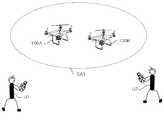
図15Aは、比較例の無人航空機を目視で操縦する状況を示す図である。2人のユーザU1,U2がそれぞれ無人航空機100A,100Bを目視で操縦する場合、ユーザU1,U2の視野CA1は広い。よって、ユーザU1,U2は、互いの無人航空機が接近するような状況を避け易い。したがって、無人航空機同士が衝突するような事態は起こりにくい。 FIG. 15A is a diagram showing a situation in which an unmanned aerial vehicle of a comparative example is visually operated. When two users U1 and U2 visually operate the unmanned
図15Bは、本実施形態の無人航空機をFPV飛行モードで操作する状況を示す図である。2人のユーザU1,U2が、端末80の表示部88を見ながら、無人航空機100A,100Bをそれぞれ操縦する場合、ユーザU1,U2の視野CA2が狭くなる。ユーザU1,U2は、ユーザU1,U2が操縦する無人航空機の近くに他の無人航空機が飛行していても、気付きにくい。したがって、無人航空機同士が衝突するような事態は起こり易い。 FIG. 15B is a diagram showing a situation in which the unmanned aerial vehicle of the present embodiment is operated in the FPV flight mode. When two users U1 and U2 operate the unmanned
また、本実施形態では、サーバ300が主導で各端末80のユーザの注目点に基づく情報提示を行うことができる。つまり、サーバ制御部310は、通信部320を介して、端末80Aから注目点tp1を取得し、端末80Bから注目点tp2を取得してよい。サーバ制御部310は、通信部320を介して、端末80Aに表示させる情報(例えば無人航空機100Bに関する情報、推奨情報)を端末80Aへ送信してよい。 Further, in the present embodiment, the
これにより、サーバ300は、飛行システム10に存在する複数の端末80が検出する注目点の情報を集約して処理し、情報提示を指示できる。よって、サーバ300は、例えば共通注目点に基づく情報提示の処理にかかる端末80の処理負荷を低減できる。 As a result, the
なお、第1動作例における手順T10及び第2動作例における手順T14Aでは、サーバ300のサーバ制御部310は、端末80に対し、他の無人航空機100に関する情報や推奨情報を送信していたが、推奨情報に対応する制御を無人航空機100に対して指示してよい。この場合、サーバ制御部310は、通信部320を介して、端末80に対し、低速飛行モードや一時停止等の飛行制御情報を送信してよい。端末80の端末制御部81は、通信部85を介して、飛行制御情報を受信すると、この飛行制御情報を基に、無人航空機100の飛行の制御を指示してよい。 In the procedure T10 in the first operation example and the procedure T14A in the second operation example, the
例えば、サーバ制御部310は、無人航空機100Aから無人航空機100Bまでの距離r1が閾値Dist1以下である場合、無人航空機100Aによる飛行の速度を制限させてよい。制限させるための制限指示情報は、無人航空機100Aに直接送信されてもよいし、端末80Aを介して送信されてもよい。 For example, the
これにより、サーバ300は、無人航空機100Aの飛行の速度の制限指示を行うことで、無人航空機100Aと無人航空機100Bとの位置関係に応じて無人航空機100Aの速度を制限させることができる。この場合、ユーザU1が無人航空機100Bの存在に気付かずに端末80Aを操作する場合でも、無人航空機100Aは、端末80Aからの指示に応じて高速に飛行することを抑制でき、無人航空機100Bとの衝突を抑制できる。 As a result, the
例えば、サーバ制御部310は、距離r1が短い程、無人航空機100Aによる飛行の速度を低速に制限させてよい。制限させるための制限指示情報は、無人航空機100Aに直接送信されてもよいし、端末80Aを介して送信されてもよい。この場合、無人航空機100Aは、無人航空機100Bと接近する程、飛行速度が低くなる。よって、無人航空機100Aと無人航空機100Bとが接近するほど衝突し易くなるが、飛行速度も低く制限されるので、サーバ300は、無人航空機100Bとの衝突を抑制できる。 For example, the
(第2の実施形態)
第1の実施形態では、複数の無人航空機100同士が接近する場合を示した。第2の実施形態では、共通の注目点である目的地に無人航空機100が接近する場合を示す。(Second embodiment)
In the first embodiment, a case where a plurality of unmanned
第2の実施形態における飛行システム10の構成は、第1の実施形態とほぼ同一の構成を有する。第1の実施形態と同一の構成要素については、同一の符号を用いることで、その説明を省略又は簡略化する。 The configuration of the
図16A及び図16Bは、第2の実施形態における、サーバ300による目的地視点での情報提示指示手順を示すシーケンス図である。図7に示した第1動作例、及び図12に示した第2動作例と同一の手順については、同一の符号を用いることで、その説明を省略又は簡略化する。 16A and 16B are sequence diagrams showing an information presentation instruction procedure from the destination viewpoint by the
まず、飛行システム10は、T1〜T6の処理を行う。 First, the
手順T7において、注目点が共通する複数の無人航空機100が存在する場合、サーバ300のサーバ制御部310は、共通する注目点から半径r2の範囲に無人航空機100が存在するか否かを判別する(T8B)。半径r2は、共通する注目点への無人航空機100の接近が予想されるとして、速度の低下を推奨するための値である。 In step T7, when there are a plurality of unmanned
なお、共通する注目点の位置情報は、サーバ300のストレージ330に保存されている地図情報から得られてよい。また、地図情報は、外部の地図サーバに蓄積され、サーバ制御部310は、通信部320を介して地図情報を取得してよい。 The location information of the common points of interest may be obtained from the map information stored in the
共通する注目点の位置から半径r2の範囲に無人航空機100が存在しない場合、サーバ制御部310、サーバ300の最初の手順に戻る。 If the unmanned
一方、共通する注目点の位置から半径r2の範囲に無人航空機100が存在する場合、サーバ制御部310は、共通する注目点から半径r3の範囲に無人航空機100が存在するか否かを判別する(T9B)。半径r3は、共通する注目点への無人航空機の衝突が予想されるとして、ホバリング等の一時停止を推奨するための値である。半径r3は、半径r2より小さな値である。 On the other hand, when the unmanned
半径r3の範囲に無人航空機100が存在しない場合、サーバ制御部310は、該当する無人航空機100(例えば半径r2の円と半径r3の円の間に位置する無人航空機100)に対応する端末80に対し、低速飛行モードを推奨する(T10B)。 When the unmanned
一方、手順T9Bで半径r3の範囲に無人航空機100が存在する場合、サーバ制御部310は、該当する無人航空機100(例えば半径r2の円の内側に位置する無人航空機100)に対応する端末80に対し、ホバリング等の一時停止を推奨する(T11B)。 On the other hand, when the unmanned
サーバ制御部310は、通信部320を介して、手順T10B又は手順T11Bの推奨情報を、該当する無人航空機100に対応する端末80に送信する(T12B)。 The
該当する無人航空機100に対応する端末80の端末制御部81は、通信部85を介して、サーバ300から推奨情報を受信する(T13A)。端末制御部81は、推奨情報に従って、表示部88に推奨画面を表示する(T14A)。 The
このように、サーバ300のサーバ制御部310は、共通注目点の位置情報を取得してよい。サーバ制御部310は、無人航空機100の位置情報を取得してよい。サーバ制御部310は、共通する注目点から無人航空機100までの距離が、共通する注目点から半径r2の範囲内(半径r2以下)である場合、端末80に、無人航空機100による飛行の速度を制限することを推奨する情報を表示させてよい。この場合、表示の指示情報が端末80へ送信されてよい。 In this way, the
共通する注目点としての目的地には、多数の無人航空機100が飛来することが想定される。そのため、他の無人航空機100も目的地に接近している場合、衝突の可能性が高くなる。ユーザは、端末80に表示された推奨情報を確認することで、飛行の速度の制限を推奨されていることを把握できる。端末80は、飛行の速度を制限するための設定を行い、飛行の速度を制限して無人航空機100を飛行させる。速度制限の設定は、推奨情報を基に、端末制御部81により自動設定されてもよいし、操作部83を介して手動設定されてもよい。速度制限されることで、ユーザは、高速に飛行させる場合よりも、端末80の画面上で無人航空機100の状態を確認し易くなり、他の無人航空機100との衝突を抑制できる。 It is assumed that a large number of unmanned
また、サーバ制御部310は、共通する注目点から前記無人航空機100までの距離が短い程、端末80に対し、無人航空機100による飛行の速度を低速に制限することを推奨する情報を表示させてよい。この場合、表示の指示情報が端末80へ送信されてよい。 Further, the
共通する注目点から無人航空機100までの距離が短く、短い移動距離でも衝突する可能性が高くなる。この場合でも、サーバ300は、共通する注目点から無人航空機100までの距離が短い程、無人航空機100を低速に飛行させる。したがって、サーバ300は、共通する注目点への移動に要する時間を長くでき、衝突を回避し易くできる。 The distance from the common point of interest to the unmanned
なお、手順T10B,T11Bでは、サーバ300のサーバ制御部310は、端末80に対し、推奨情報を送信していたが、推奨情報に対応する制御を無人航空機100に対して指示してもよい。この場合、サーバ制御部310は、通信部320を介して、端末80に対し、低速飛行モードや一時停止等の飛行制御情報を送信してよい。端末80の端末制御部81は、通信部85を介して、飛行制御情報を受信すると、この飛行制御情報を基に、無人航空機100の飛行の制御を指示してよい。 In the procedures T10B and T11B, the
例えば、サーバ制御部310は、共通注目点と無人航空機100Aとの距離が半径r2以下である場合、無人航空機100Aによる飛行の速度を制限させてよい。制限させるための制限指示情報は、無人航空機100Aに直接送信されてもよいし、端末80Aを介して送信されてもよい。 For example, the
これにより、サーバ300は、無人航空機100Aの飛行の速度の制限指示を行うことで、無人航空機100Aと共通注目点との位置関係に応じて無人航空機100Aの速度を制限させることができる。この場合、ユーザU1が共通注目点の存在に気付かずに端末80Aを操作する場合でも、無人航空機100Aは、端末80Aからの指示に応じて高速に飛行することを抑制でき、共通注目点(目的地)に存在するオブジェクトや共通注目点に接近している他の無人航空機100Bとの衝突を抑制できる。 As a result, the
例えば、サーバ制御部310は、共通注目点と無人航空機100Aとの距離が短い程、無人航空機100Aによる飛行の速度を低速に制限させてよい。制限させるための制限指示情報は、無人航空機100Aに直接送信されてもよいし、端末80Aを介して送信されてもよい。 For example, the
例えば、サーバ制御部310は、複数の無人航空機100が共通する注目点である目的地に同時に接近する場合、所定の順序に従って、各無人航空機100が順番に共通注目点に近づくように制御してもよい。この制御情報は、無人航空機100Aに直接送信されてもよいし、端末80Aを介して送信されてもよい。これにより、サーバ300は、無人航空機100同士の衝突を回避しつつ、各無人航空機100を目的地に到達させることができる。 For example, when a plurality of unmanned
(第3の実施形態)
第1及び第2の実施形態では、サーバ300が無人航空機100の衝突回避のための情報提示指示の動作を行う場合を示した。第3の実施形態では、複数の端末80のうちいずれかの端末80Pが、無人航空機100の衝突回避のための情報提示指示の動作を行う場合を示す。(Third embodiment)
In the first and second embodiments, the case where the
第3の実施形態の飛行システム10は、第1の実施形態とほぼ同一の構成を有する。第1の実施形態と同一の構成要素については同一の符号を用いることで、その説明を省略又は簡略化する。 The
第3の実施形態では、端末80Pの端末制御部81が、サーバ300が無人航空機100の衝突回避のための情報提示指示に関する処理を行う。端末制御部81は、無人航空機100により撮像された画像におけるユーザの注目点に基づいて、情報を提示させる。つまり、端末制御部81は、第1及び第2の実施形態におけるサーバ300のサーバ制御部310が実施する処理と同様の処理を行ってよい。端末制御部81は、処理部の一例である。 In the third embodiment, the
第3の実施形態では、端末80を、主に端末80P又はその他の端末80Qとして説明する。端末80Qは、複数存在してもよい。端末80Pは、無人航空機100Pの飛行の制御を指示し、ユーザUpによって操作されるとする。また、端末80Qは、無人航空機100Qの飛行の制御を指示し、ユーザUqによって操作されるとする。端末80Pは、端末80Aであってよい。端末80Qは、端末80Bであってよい。無人航空機100Pは、無人航空機100Aであってよい。無人航空機100Qは、無人航空機100Bであってよい。なお、共通注目点に基づく情報提示指示を行う端末80Pと、その他の端末80Qとは、予め通信可能となるように通信リンクを接続してよい。 In the third embodiment, the terminal 80 will be described mainly as the terminal 80P or other terminal 80Q. There may be a plurality of
(第3の実施形態の第1動作例)
図17は、第3の実施形態の第1動作例における、端末80による無人航空機視点での情報提示指示手順を示すシーケンス図である。第1の実施形態の第1動作例における、図7と同一のステップ処理については、同一のステップ番号を付すことで、その説明を省略又は簡略化する。(First operation example of the third embodiment)
FIG. 17 is a sequence diagram showing an information presentation instruction procedure from the viewpoint of an unmanned aerial vehicle by the terminal 80 in the first operation example of the third embodiment. The same step processing as in FIG. 7 in the first operation example of the first embodiment is given the same step number, and the description thereof will be omitted or simplified.
また、ここでは、複数の端末80のうち、第1の実施形態の第1動作例における、サーバの動作と同様の動作を行う端末を、特定の端末80Pとする。端末80Pは、情報処理装置の一例である。 Further, here, among the plurality of
まず、飛行システム10は、T1〜T5の処理を行う。 First, the
第1の実施形態の無人航空機100及び端末80と同様に、無人航空機100Pでは、撮像装置220は、繰り返し撮像する。UAV制御部110は、撮像装置220による撮像画像をメモリ160に記録し、撮像画像に関する付加情報もメモリ160に記録してよい。UAV制御部110は、メモリ160に記憶された撮像画像及びその付加情報を、通信インタフェース150を介して、端末80Pに送信する。 Similar to the unmanned
端末80Pでは、端末制御部81は、通信部85を介して、無人航空機100Pから送信された撮像画像及びその付加情報を受信する(T3C)。端末制御部81は、端末80Pを操作するユーザUpの注目点を検出し、メモリ87に記憶させる(T4C)。また、端末制御部81は、端末制御部81は、通信部85を介して、他の端末80Qから送信された注目点を含む情報を受信し、メモリ87に記憶させる(T6C)。したがって、端末80Pは、自機としての端末80PのユーザUpの注目点を自機で検出して取得し、他の端末80QのユーザUqの注目点を他の端末80Qから取得する。 In the terminal 80P, the
端末制御部81は、メモリ87に記憶された複数の注目点の情報のうち、共通する複数の注目点の情報が存在するか否かを判別する(T7C)。共通する複数の注目点の情報が存在しない場合、端末制御部81は、端末80Pにおける最初の手順T3Cに戻る。 The
一方、手順T7Cにおいて、共通する複数の注目点の情報が存在する場合、端末制御部81は、通信部85を介して、共通する注目点の情報を送信した端末80Qに対し、他の無人航空機100(例えば無人航空機100P)の情報を送信する(T8C)。これにより、共通する注目点の情報を送信した端末80Qは、端末80Pからの情報提示指示を受けて、表示部88に表示された撮像画像に、他の無人航空機100Pの存在を表すマークを、重畳画像として重畳して表示することができる。 On the other hand, in the procedure T7C, when there is information on a plurality of common points of interest, the
また、自端末(端末80P)と共通する注目点の情報を送信した他の端末80Qが存在する場合、端末80Pの端末制御部81は、他の端末80Qが飛行の制御を指示する他の無人航空機100Qの情報を基に、表示部88に表示された撮像画像に、他の無人航空機100Qの存在を表すマークを重畳して表示する(T10C)。 Further, when there is another terminal 80Q that has transmitted information on a point of interest common to the own terminal (terminal 80P), the
このように、第3の実施形態の第1動作例では、共通注目点に注目するユーザUpが操縦する無人航空機100P(自機)と他の無人航空機100Qが存在する場合、端末80Pの表示部88に表示された撮像画像に、他の無人航空機100Qが現れていなくても、他の無人航空機100Qを表すマークが表示される。これにより、ユーザUpは、ユーザUpが注目する注目点と共通する注目点に注目するユーザUqに対応する他の無人航空機100Qが存在することを把握できる。また、端末80Pが共通注目点に基づく情報提示指示を行うことで、サーバ300の設置を省くことができ、飛行システム10を簡単な構成にすることができ、コスト削減できる。 As described above, in the first operation example of the third embodiment, when the unmanned aerial vehicle 100P (own aircraft) operated by the user Up paying attention to the common point of interest and another unmanned aerial vehicle 100Q exist, the display unit of the terminal 80P. Even if the other unmanned aerial vehicle 100Q does not appear in the captured image displayed on the 88, a mark representing the other unmanned aerial vehicle 100Q is displayed. As a result, the user Up can grasp that there is another unmanned aerial vehicle 100Q corresponding to the user Uq who pays attention to the attention point common to the attention point which the user Up pays attention to. Further, since the terminal 80P gives an information presentation instruction based on the common point of interest, the installation of the
(第3の実施形態の第2動作例)
図18A及び図18Bは、第3の実施形態の第2動作例における、端末80による無人航空機視点での情報提示指示手順を示すシーケンス図である。第1の実施形態の第2動作例における図12や第1の実施形態の第1動作例における図17と同一のステップ処理については、同一のステップ番号を付すことで、その説明を省略又は簡略化する。(Second operation example of the third embodiment)
18A and 18B are sequence diagrams showing an information presentation instruction procedure from the viewpoint of an unmanned aerial vehicle by the terminal 80 in the second operation example of the third embodiment. The same step processing as in FIG. 12 in the second operation example of the first embodiment and FIG. 17 in the first operation example of the first embodiment is given the same step number, and the description thereof is omitted or simplified. To become.
また、ここでは、複数の端末80のうち、第1の実施形態の第1動作例における、サーバ300の動作と同様の動作を行う端末を、特定の端末80Pとする。 Further, here, among the plurality of
まず、飛行システム10は、T1〜T5,T3D,T4D,T6Dの処理を行う。手順T3Dは、図17に示した手順T3Cと同様の処理である。手順T4Dは、図17に示した手順T4Cと同様の処理である。手順T6Dは、図17に示した手順T6Cと同様の処理である。 First, the
端末80Pでは、端末制御部81は、メモリ87に記憶された複数の注目点の情報のうち、共通する複数の注目点の情報が存在するか否かを判別する(T7D)。共通する複数の注目点の情報が存在しない場合、端末制御部81は、端末80Pにおける最初の手順T3Dに戻る。 In the terminal 80P, the
一方、手順T7Dにおいて、共通する複数の注目点の情報が存在する場合、端末制御部81は、無人航空機100Pから他の無人航空機100Qまでの距離r1が閾値Dist1以下であるか否かを判別する(T8D)。 On the other hand, in the procedure T7D, when there is information on a plurality of common points of interest, the
距離r1が閾値Dist1以下でない場合、端末制御部81は、端末80Pにおける最初の手順T3Dに戻る。 If the distance r1 is not less than or equal to the threshold Dist1, the
一方、距離r1が閾値Dist1以下である場合、端末制御部81は、距離r1が閾値Dist2以下であるか否かを判別する(T9D)。距離r1が閾値Dist2以下でない場合、端末制御部81は、低速飛行モードを推奨し、低速飛行モードを推奨するための推奨情報を生成する(T10D)。一方、手順T9Dで距離r1が閾値Dist2以下である場合、端末制御部81は、ホバリング等の一時停止(一時停止モード)を推奨し、一時停止を推奨するための推奨情報を生成する(T11D)。 On the other hand, when the distance r1 is equal to or less than the threshold value Dist1, the
端末制御部81は、手順T10D又は手順T11Dの推奨情報を、通信部85を介して他の無人航空機100Qの飛行の制御を指示する他の端末80Qに送信する(T12D)。 The
他の端末80Qの端末制御部81は、通信部85を介して、端末80Pから推奨情報を受信する(T13D)。端末制御部81は、推奨情報に従って、表示部88に推奨情報を含む推奨画面を表示する(T14D)。これにより、共通注目点に基づく情報提示指示を受ける他の端末80Qは、表示部88に推奨画面を表示できる。よって、他の端末80QのユーザUqは、他の無人航空機100Qの操縦時に推奨画面を参照して、操縦できるので、操縦の安全性を向上できる。 The
また、自端末(端末80P)と共通する注目点の情報を送信した他の端末80Qが存在する場合、端末80Pの端末制御部81は、表示部88に推奨情報を含む推奨画面を表示する(T15D)。これにより、共通注目点に基づく情報提示指示を行う端末80Pは、表示部88に推奨画面を表示できる。よって、端末80PのユーザUpは、無人航空機100Pの操縦時に推奨画面を参照して、操縦できるので、操縦の安全性を向上できる。 Further, when there is another terminal 80Q that has transmitted information on the point of interest common to the own terminal (terminal 80P), the
第3の実施形態の第2動作例では、複数の無人航空機100(例えば無人航空機100P,100Q)が接近している場合、低速飛行モードが推奨される。また、複数の無人航空機100が衝突する可能性が高い場合、ホバリング等の一時停止が推奨される。これにより、無人航空機100同士の衝突の回避に繋がる。また、サーバ300の設置を省くことができ、飛行システム10を簡単な構成にすることができ、コスト削減できる。 In the second operation example of the third embodiment, when a plurality of unmanned aerial vehicles 100 (for example, unmanned aerial vehicles 100P, 100Q) are approaching, a low speed flight mode is recommended. Further, when there is a high possibility that a plurality of unmanned
このように、端末80Pでは、端末制御部81は、通信部85を介して、無人航空機100Pから撮像画像GZ1を取得する。端末制御部81は、撮像画像GZ1における注目点tp1を検出する。端末制御部81は、通信部85を介して、他の端末80Qから注目点tp2を取得する。端末制御部81は、端末80Pに表示させる情報(例えば他の無人航空機100Qに関する情報、推奨情報)を、表示部88に表示させる。 As described above, in the terminal 80P, the
これにより、端末80Pは、注目点の検出から、共通注目点の判定や共通注目点の判定に基づく情報の表示までの一連の処理を行うことができる。よって、端末80Pは、注目点の検出や、共通注目点の判定に基づく情報の表示を指示するサーバ300を別途設けることを不要にできる。したがって、端末80Pは、共通注目点の検出に基づく情報を表示するための構成を簡略化できる。 As a result, the
(第4の実施形態)
第3の実施形態では、端末80としてのスマートフォン80Sが、無人航空機100の飛行の制御を指示する場合を示した。第4の実施形態では、端末80としてのHMD(Head Mount Display)500が、無人航空機100の飛行の制御を指示する場合を示す。(Fourth Embodiment)
In the third embodiment, the case where the smartphone 80S as the terminal 80 instructs the control of the flight of the unmanned
また、第4の実施形態の飛行システム10は、端末80がHMD500となる他、第1の実施形態とほぼ同一の構成を有する。第1の実施形態と同一の構成要素については、同一の符号を用いることで、その説明を省略又は簡略化する。 Further, the
図19は、第4の実施形態におけるHMD500の外観を示す斜視図である。HMD500は、ユーザの頭部に装着されるマウント部510と、マウント部510に支持された本体部520とを有する。 FIG. 19 is a perspective view showing the appearance of the
図20は、HMD500のハードウェア構成を示すブロック図である。HMD500は、処理部521、通信部522、記憶部523、操作部524、表示部525、加速度センサ526、撮像部527及びインタフェース部528を有する。HMD500のこれらの各構成部は、本体部520に設けられてよい。 FIG. 20 is a block diagram showing a hardware configuration of the
処理部521は、例えばCPU、MPU又はDSPを用いて構成される。処理部521は、本体部520の各部の動作を統括して制御するための信号処理、他の各部との間のデータの入出力処理、データの演算処理及びデータの記憶処理を行う。 The
処理部521は、通信部522を介して、無人航空機100からのデータや情報を取得してよい。処理部521は、操作部524を介して入力されたデータや情報を取得してよい。処理部521は、記憶部523に保持されたデータや情報を取得してよい。処理部521は、無人航空機100の撮像画像を含む、データや情報を表示部525に送り、このデータや情報に基づく表示情報を表示部525に表示させてよい。処理部521は、無人航空機100の制御を指示するためのアプリケーションを実行してよい。処理部521は、アプリケーションで用いられる各種のデータを生成してよい。 The
処理部521は、撮像部527で撮像されたユーザの目の画像を基に、視線検出を行い、第1の実施形態と同様、注目点を検出してよい。また、処理部521は、視線検出の検出結果に従って、無人航空機100の飛行の制御を指示してよい。つまり、処理部521は、視線の動きに伴って無人航空機100を操縦してよい。例えば、処理部521は、HMD500を装着したユーザが見ている画面上の位置に対応する地理的な位置やオブジェクトの方向に向かって無人航空機100が飛行するよう、通信部522を介して無人航空機100に指示してよい。よって、ユーザの注目点が無人航空機100の目的地となってよい。 The
処理部521は、加速度センサ526により検出された加速度の情報を取得し、加速度に基づいて、無人航空機100の飛行の制御を指示してよい。例えば、処理部521は、HMD500を装着したユーザが頭部を傾けた方向に向かって無人航空機100が飛行するよう、通信部522を介して無人航空機100に指示してよい。 The
通信部522は、各種の無線通信方式により無人航空機100との間で通信する。無線通信方式は、例えば、無線LAN、Bluetooth(登録商標)、近距離無線通信、又は公衆無線回線を介した通信を含んでよい。また、通信部522は、有線を介して通信してもよい。 The
記憶部523は、例えばHMD500の動作を規定するプログラムや設定値のデータが格納されたROMと、処理部521の処理時に使用される各種の情報やデータを一時的に保存するRAMを有してよい。記憶部523は、HMD500から取り外し可能に設けられてよい。プログラムは、アプリケーションプログラムを含んでよい。 The
操作部524は、ユーザにより入力されるデータや情報を受け付ける。操作部524は、ボタン、キー、タッチパネル、タッチパッド、マイクロホン、等を含んでよい。操作部524は、例えばトラッキング、タップフライ等の操作を受け付けてよい。 The
表示部525は、例えばLCD(Liquid Crystal Display)を用いて構成され、処理部521から出力された各種の情報やデータを表示する。表示部525は、無人航空機100の撮像装置220により撮像された撮像画像のデータを表示してよい。 The
加速度センサ526は、HMD500の姿勢を検知可能な3軸加速度センサでよい。加速度センサ526は、検知した姿勢情報を操作情報の1つとして、処理部521に出力してよい。 The
撮像部527は、各種画像を撮像する。撮像部527は、ユーザが視ている方向、つまり視線検出を行うために、ユーザの目を撮像し、処理部521に出力してよい。インタフェース部528は、外部機器との間で情報やデータの入出力を行う。 The
HMD500は、第1〜第3の実施形態と同様の動作を行うことが可能である。したがって、端末80がHMD500であっても、第1〜第3の実施形態と同様の効果が得られる。また、ユーザは、HMD500を装着すると、HMD500を装着しない場合と比較して、HMD500の外部への視界が大きく遮られるので、より臨場感を高くして画像を視認でき、無人航空機100のFPV飛行の飛行制御指示を楽しむことができる。また、HMD500は、処理部521で検出された注目点に基づく共通注目点の有無に基づく情報提示を受けることで、HMD500により飛行の制御の指示を行う無人航空機100以外の他の無人航空機100の情報や推奨情報を表示部525に表示できる。よって、HMD500を装着したユーザは、HMD500の外部への視界が大きく遮られても、提示された情報を確認することで、HMD500を用いた無人航空機100の操縦に係る安全性を向上できる。 The
なお、HMD500は、加速度センサ526により検出された加速度に基づいて無人航空機100の飛行の制御を指示可能である場合、送信機50の左右の制御棒を用いた操作に基づく無人航空機100の飛行の制御の指示と同様に指示可能である。したがって、この場合、飛行システム10が送信機50を備えなくてもよい。 When the
また、HMD500は、加速度センサ526により検出された加速度に基づいて無人航空機100の飛行の制御を指示することができなくてもよい。この場合、ユーザは、HMD500の表示部525を確認しながら、送信機50を用いて無人航空機100を操縦してもよい。 Further, the
以上、本開示を実施形態を用いて説明したが、本開示の技術的範囲は上述した実施形態に記載の範囲には限定されない。上述した実施形態に、多様な変更又は改良を加えることが当業者に明らかである。その様な変更又は改良を加えた形態も本開示の技術的範囲に含まれ得ることが、特許請求の範囲の記載からも明らかである。 Although the present disclosure has been described above using the embodiments, the technical scope of the present disclosure is not limited to the scope described in the above-described embodiments. It will be apparent to those skilled in the art to make various changes or improvements to the embodiments described above. It is clear from the description of the claims that the form with such changes or improvements may be included in the technical scope of the present disclosure.
特許請求の範囲、明細書、及び図面中において示した装置、システム、プログラム、及び方法における動作、手順、ステップ、及び段階等の各処理の実行順序は、特段「より前に」、「先立って」等と明示しておらず、前の処理の出力を後の処理で用いるのでない限り、任意の順序で実現可能である。特許請求の範囲、明細書、及び図面中の動作フローに関して、便宜上「先ず、」、「次に」等を用いて説明したとしても、この順で実施することが必須であることを意味するものではない。 The order of execution of each process such as operation, procedure, step, step in the device, system, program, and method shown in the claims, the specification, and the drawing is particularly "before" and "prior to". , Etc., and can be realized in any order unless the output of the previous process is used in the subsequent process. Even if the scope of claims, the specification, and the operation flow in the drawings are explained using "first", "next", etc. for convenience, it means that it is essential to carry out in this order. is not it.
10 飛行システム
50 送信機
50B 筐体
53L 左制御棒
53R 右制御棒
61 送信機制御部
63 無線通信部
65 インタフェース部
80,80A,80B 端末
81 端末制御部
82 インタフェース部
83 操作部
85 通信部
87 メモリ
88,88A,88B 表示部
89 撮像部
100,100A,100B 無人航空機
102 UAV本体
110 UAV制御部
150 通信インタフェース
160 メモリ
200 ジンバル
210 回転翼機構
211 回転翼
212 駆動モータ
213 電流センサ
220 撮像装置
240 GPS受信機
250 慣性計測装置
260 磁気コンパス
270 気圧高度計
280 超音波センサ
290 レーザー測定器
300 サーバ
310 サーバ制御部
320 通信部
330 ストレージ
340 メモリ
500 HMD
510 マウント部
520 本体部
521 処理部
522 通信部
523 記憶部
524 操作部
525 表示部
526 加速度センサ
527 撮像部
528 インタフェース部
AN1,AN2 アンテナ
B1 電源ボタン
B2 RTHボタン
CA1,CA2 視野
Dist1,Dist2 閾値
GM1,GM2 推奨画面
GZ1,GZ2 撮像画像
J1 タワー
J2 橋
J3 ビル
mk1,mk2 マーク
r1 距離
r2,r3 半径
tp1,tp2 注目点
U1,U2 ユーザ10
510
Claims (24)
Translated fromJapanese処理部を備え、
前記処理部は、
第1の飛行体の制御を指示する第1の端末を操作する第1のユーザが前記第1の飛行体により撮像された第1の画像において注目する第1の注目点と、第2の飛行体の制御を指示する第2の端末を操作する第2のユーザが前記第2の飛行体により撮像された第2の画像において注目する第2の注目点と、を取得し、
前記第1の注目点と前記第2の注目点が、同じ注目点を示す共通注目点であるか否かを判定し、
前記共通注目点である場合、前記第1の端末に、前記第2の飛行体に関する情報を提示させる、
情報処理装置。An information processing device that presents information based on the user's point of interest in an image captured by an air vehicle.
Equipped with a processing unit
The processing unit
A first point of interest and a second flight that the first user who operates the first terminal instructing control of the first flying object pays attention in the first image captured by the first flying object. The second user who operates the second terminal instructing the control of the body acquires the second attention point to be focused on in the second image captured by the second flying object.
It is determined whether or not the first attention point and the second attention point are common attention points indicating the same attention point.
If it is the common point of interest, the first terminal is made to present information about the second flying object.
Information processing device.
前記第1の飛行体が移動しているか否かを判定し、
前記第1の飛行体が移動している場合、前記第1の端末に、前記第2の飛行体に関する情報を提示させる、
請求項1に記載の情報処理装置。The processing unit
It is determined whether or not the first flying object is moving, and it is determined.
When the first flying object is moving, the first terminal is made to present information about the second flying object.
The information processing apparatus according to claim 1.
前記第1の飛行体の位置情報を取得し、
前記第2の飛行体の位置情報を取得し、
前記第1の飛行体と前記第2の飛行体との距離である第1の距離が第1の閾値以下である場合、前記第1の端末に、前記第2の飛行体に関する情報を提示させる、
請求項1または2に記載の情報処理装置。The processing unit
Obtaining the position information of the first aircraft,
Obtaining the position information of the second aircraft,
When the first distance, which is the distance between the first flying object and the second flying object, is equal to or less than the first threshold value, the first terminal is made to present information about the second flying object. ,
The information processing apparatus according to claim 1 or 2.
前記第1の飛行体の位置情報を取得し、
前記第2の飛行体の位置情報を取得し、
前記第1の端末の画面における、前記第1の飛行体の位置に対する前記第2の飛行体の位置に基づく位置に、前記第2の飛行体の存在を示す情報を提示させる、
請求項1〜3のいずれか1項に記載の情報処理装置。The processing unit
Obtaining the position information of the first aircraft,
Obtaining the position information of the second aircraft,
Information indicating the existence of the second flying object is presented at a position based on the position of the second flying object with respect to the position of the first flying object on the screen of the first terminal.
The information processing apparatus according to any one of claims 1 to 3.
前記第1の飛行体の位置情報を取得し、
前記第2の飛行体の位置情報を取得し、
前記第1の飛行体と前記第2の飛行体との距離である第1の距離が第1の閾値以下である場合、前記第1の端末に、前記第1の飛行体による飛行の速度を制限することを推奨する第1の推奨情報を提示させる、
請求項1〜4のいずれか1項に記載の情報処理装置。The processing unit
Obtaining the position information of the first aircraft,
Obtaining the position information of the second aircraft,
When the first distance, which is the distance between the first flying object and the second flying object, is equal to or less than the first threshold value, the speed of flight by the first flying object is transmitted to the first terminal. Have them present the first recommendation information that they recommend to limit,
The information processing apparatus according to any one of claims 1 to 4.
請求項5に記載の情報処理装置。The processing unit presents the first recommended information that recommends limiting the speed of flight by the first flying object to a lower speed as the first distance is shorter.
The information processing apparatus according to claim 5.
前記共通注目点の位置情報を取得し、
前記第1の飛行体の位置情報を取得し、
前記共通注目点と前記第1の飛行体との距離である第2の距離が第2の閾値以下である場合、前記第1の端末に、前記第1の飛行体による飛行の速度を制限することを推奨する第2の推奨情報を提示させる、
請求項1〜6のいずれか1項に記載の情報処理装置。The processing unit
Acquire the position information of the common point of interest and
Obtaining the position information of the first aircraft,
When the second distance, which is the distance between the common point of interest and the first flying object, is equal to or less than the second threshold value, the first terminal limits the speed of flight by the first flying object. Have them present a second recommendation, which recommends that
The information processing apparatus according to any one of claims 1 to 6.
請求項7に記載の情報処理装置。The processing unit is made to present the second recommended information recommending that the shorter the second distance is, the lower the speed of flight by the first flying object is.
The information processing apparatus according to claim 7.
通信部、を更に備え、
前記処理部は、
前記通信部を介して、前記第1の端末から前記第1の注目点を取得し、前記第2の端末から前記第2の注目点を取得し、
前記通信部を介して、前記第1の端末に提示させる情報を前記第1の端末へ送信する、
請求項1〜8のいずれか1項に記載の情報処理装置。The information processing device is a server.
Further equipped with a communication unit,
The processing unit
The first attention point is acquired from the first terminal and the second attention point is acquired from the second terminal via the communication unit.
Information to be presented to the first terminal is transmitted to the first terminal via the communication unit.
The information processing apparatus according to any one of claims 1 to 8.
通信部及び提示部、を更に備え、
前記処理部は、
前記通信部を介して、前記第1の飛行体から前記第1の画像を取得し、
前記第1の画像における前記第1の注目点を検出し、
前記通信部を介して、前記第2の端末から前記第2の注目点を取得し、
前記第1の端末に提示させる情報を、前記提示部に提示させる、
請求項1〜8のいずれか1項に記載の情報処理装置。The information processing device is the first terminal.
Further equipped with a communication unit and a presentation unit,
The processing unit
The first image is acquired from the first flying object via the communication unit.
The first point of interest in the first image is detected and
The second point of interest is acquired from the second terminal via the communication unit.
Information to be presented to the first terminal is presented to the presentation unit.
The information processing apparatus according to any one of claims 1 to 8.
第1の飛行体の制御を指示する第1の端末を操作する第1のユーザが前記第1の飛行体により撮像された第1の画像において注目する第1の注目点と、第2の飛行体の制御を指示する第2の端末を操作する第2のユーザが前記第2の飛行体により撮像された第2の画像において注目する第2の注目点と、を取得するステップと、
前記第1の注目点と前記第2の注目点が、同じ注目点を示す共通注目点であるか否かを判定するステップと、
前記共通注目点である場合、前記第1の端末に、前記第2の飛行体に関する情報を提示させるステップと、
を含む、情報提示指示方法。It is an information presentation instruction method in an information processing device that presents information based on a user's point of interest in an image captured by an air vehicle.
A first point of interest and a second flight that the first user who operates the first terminal instructing control of the first flying object pays attention in the first image captured by the first flying object. A step of acquiring a second attention point to be focused on in a second image captured by the second flying object by a second user who operates a second terminal instructing body control, and
A step of determining whether or not the first attention point and the second attention point are common attention points indicating the same attention point, and
In the case of the common point of interest, the step of causing the first terminal to present information about the second flying object, and
Information presentation instruction method including.
前記第2の飛行体に関する情報を提示させるステップは、前記第1の飛行体が移動している場合、前記第1の端末に、前記第2の飛行体に関する情報を提示させるステップを含む、
請求項11に記載の情報提示指示方法。Further including, a step of determining whether or not the first flying object is moving, is included.
The step of presenting information about the second air vehicle includes a step of causing the first terminal to present information about the second air vehicle when the first air vehicle is moving.
The information presentation instruction method according to claim 11.
前記第2の飛行体の位置情報を取得するステップと、を更に含み、
前記第2の飛行体に関する情報を提示させるステップは、前記第1の飛行体と前記第2の飛行体との距離である第1の距離が第1の閾値以下である場合、前記第1の端末に、前記第2の飛行体に関する情報を提示させるステップを含む、
請求項11または12に記載の情報提示指示方法。The step of acquiring the position information of the first aircraft and
Further including the step of acquiring the position information of the second aircraft.
The step of presenting information about the second flying object is the first step when the first distance, which is the distance between the first flying object and the second flying object, is equal to or less than the first threshold value. Including a step of causing the terminal to present information about the second aircraft.
The information presentation instruction method according to claim 11 or 12.
前記第2の飛行体の位置情報を取得するステップと、を更に含み、
前記第2の飛行体に関する情報を提示させるステップは、前記第1の端末の画面における、前記第1の飛行体の位置に対する前記第2の飛行体の位置に基づく位置に、前記第2の飛行体の存在を示す情報を提示させるステップを含む、
請求項11〜13のいずれか1項に記載の情報提示指示方法。The step of acquiring the position information of the first aircraft and
Further including the step of acquiring the position information of the second aircraft.
The step of presenting information about the second flight is to make the second flight at a position based on the position of the second flight with respect to the position of the first flight on the screen of the first terminal. Including the step of presenting information indicating the existence of the body,
The information presentation instruction method according to any one of claims 11 to 13.
前記第2の飛行体の位置情報を取得するステップと、
前記第1の飛行体と前記第2の飛行体との距離である第1の距離が第1の閾値以下である場合、前記第1の端末に、前記第1の飛行体による飛行の速度を制限することを推奨する第1の推奨情報を提示させるステップと、を更に含む、
請求項11〜14のいずれか1項に記載の情報提示指示方法。The step of acquiring the position information of the first aircraft and
The step of acquiring the position information of the second aircraft and
When the first distance, which is the distance between the first flying object and the second flying object, is equal to or less than the first threshold value, the speed of flight by the first flying object is transmitted to the first terminal. Further including, and a step of prompting the presentation of the first recommended information that is recommended to be restricted.
The information presentation instruction method according to any one of claims 11 to 14.
請求項15に記載の情報提示指示方法。The step of presenting the first recommended information is a step of presenting the first recommended information that recommends limiting the speed of flight by the first flying object to a lower speed as the first distance is shorter. including,
The information presentation instruction method according to claim 15.
前記第1の飛行体の位置情報を取得するステップと、
前記共通注目点と前記第1の飛行体との距離である第2の距離が第2の閾値以下である場合、前記第1の端末に、前記第1の飛行体による飛行の速度を制限することを推奨する第2の推奨情報を提示させるステップと、を更に含む、
請求項11〜16のいずれか1項に記載の情報提示指示方法。The step of acquiring the position information of the common point of interest and
The step of acquiring the position information of the first aircraft and
When the second distance, which is the distance between the common point of interest and the first flying object, is equal to or less than the second threshold value, the first terminal limits the speed of flight by the first flying object. Further includes, with a second step of prompting the recommendation information.
The information presentation instruction method according to any one of claims 11 to 16.
請求項17に記載の情報提示指示方法。The step of presenting the second recommended information is a step of presenting the second recommended information that recommends that the shorter the second distance is, the lower the speed of flight by the first flying object is. including,
The information presentation instruction method according to claim 17.
前記第1の注目点と前記第2の注目点とを取得するステップは、
前記第1の端末から前記第1の注目点を受信するステップと、
前記第2の端末から前記第2の注目点を受信するステップと、を含み、
前記第2の飛行体に関する情報を提示させるステップは、前記第1の端末に提示させる情報を前記第1の端末へ送信するステップを含む、
請求項11〜18のいずれか1項に記載の情報提示指示方法。The information processing device is a server.
The step of acquiring the first attention point and the second attention point is
The step of receiving the first point of interest from the first terminal, and
Including the step of receiving the second point of interest from the second terminal.
The step of presenting information about the second flying object includes a step of transmitting information to be presented to the first terminal to the first terminal.
The information presentation instruction method according to any one of claims 11 to 18.
前記第1の注目点と前記第2の注目点とを取得するステップは、
前記第1の飛行体から前記第1の画像を受信するステップと、
前記第1の画像における前記第1の注目点を検出するステップと、
前記第2の端末から前記第2の注目点を受信するステップと、を含み、
前記第2の飛行体に関する情報を提示させるステップは、前記第1の端末に提示させる情報を、前記第1の端末が備える提示部に提示させるステップを含む、
請求項11〜18のいずれか1項に記載の情報提示指示方法。The information processing device is the first terminal.
The step of acquiring the first attention point and the second attention point is
The step of receiving the first image from the first flying object, and
The step of detecting the first point of interest in the first image, and
Including the step of receiving the second point of interest from the second terminal.
The step of presenting the information regarding the second flying object includes a step of causing the presenting unit included in the first terminal to present the information to be presented to the first terminal.
The information presentation instruction method according to any one of claims 11 to 18.
第1の飛行体の制御を指示する第1の端末を操作する第1のユーザが前記第1の飛行体により撮像された第1の画像において注目する第1の注目点と、第2の飛行体の制御を指示する第2の端末を操作する第2のユーザが前記第2の飛行体により撮像された第2の画像において注目する第2の注目点と、を取得するステップと、
前記第1の注目点と前記第2の注目点が、同じ注目点を示す共通注目点であるか否かを判定するステップと、
前記共通注目点である場合、前記第1の端末に、前記第2の飛行体に関する情報を提示させるステップと、
を実行させるためのプログラム。An information processing device that presents information based on the user's point of interest in an image captured by an air vehicle.
A first point of interest and a second flight that the first user who operates the first terminal instructing control of the first flying object pays attention in the first image captured by the first flying object. A step of acquiring a second attention point to be focused on in the second image captured by the second flying object by a second user who operates a second terminal instructing body control, and
A step of determining whether or not the first attention point and the second attention point are common attention points indicating the same attention point, and
In the case of the common point of interest, the step of causing the first terminal to present information about the second flying object, and
A program to execute.
第1の飛行体の制御を指示する第1の端末を操作する第1のユーザが前記第1の飛行体により撮像された第1の画像において注目する第1の注目点と、第2の飛行体の制御を指示する第2の端末を操作する第2のユーザが前記第2の飛行体により撮像された第2の画像において注目する第2の注目点と、を取得するステップと、
前記第1の注目点と前記第2の注目点が、同じ注目点を示す共通注目点であるか否かを判定するステップと、
前記共通注目点である場合、前記第1の端末に、前記第2の飛行体に関する情報を提示させるステップと、
を実行させるためのプログラムを記録したコンピュータ読取り可能な記録媒体。An information processing device that presents information based on the user's point of interest in an image captured by an air vehicle.
A first point of interest and a second flight that the first user who operates the first terminal instructing control of the first flying object pays attention in the first image captured by the first flying object. A step of acquiring a second attention point to be focused on in a second image captured by the second flying object by a second user who operates a second terminal instructing body control, and
A step of determining whether or not the first attention point and the second attention point are common attention points indicating the same attention point, and
In the case of the common point of interest, the step of causing the first terminal to present information about the second flying object, and
A computer-readable recording medium that contains a program for executing the program.
前記第1のユーザの目が注目する前記第1の画像の座標に基づいて、前記第1の注目点を取得し、The first point of interest is acquired based on the coordinates of the first image that the eyes of the first user are paying attention to.
前記第2のユーザの目が注目する前記第2の画像の座標に基づいて、前記第2の注目点を取得する、The second point of interest is acquired based on the coordinates of the second image that the eyes of the second user are paying attention to.
請求項1〜10のいずれか1項に記載の情報処理装置。The information processing apparatus according to any one of claims 1 to 10.
前記第1のユーザの目が注目する前記第1の画像の座標に基づいて、前記第1の注目点を取得するステップと、A step of acquiring the first point of interest based on the coordinates of the first image that the eyes of the first user are paying attention to.
前記第2のユーザの目が注目する前記第2の画像の座標に基づいて、前記第2の注目点を取得するステップと、を含む、A step of acquiring the second point of interest based on the coordinates of the second image of interest by the eyes of the second user.
請求項11〜20のいずれか1項に記載の情報提示指示方法。The information presentation instruction method according to any one of claims 11 to 20.
Priority Applications (4)
| Application Number | Priority Date | Filing Date | Title |
|---|---|---|---|
| JP2018086903AJP6974247B2 (en) | 2018-04-27 | 2018-04-27 | Information processing equipment, information presentation instruction method, program, and recording medium |
| CN201980003178.2ACN110785720A (en) | 2018-04-27 | 2019-04-19 | Information processing device, information presentation instruction method, program, and recording medium |
| PCT/CN2019/083477WO2019206044A1 (en) | 2018-04-27 | 2019-04-19 | Information processing device, instruction method for providing notification information, program, and recording medium |
| US17/075,089US20210034052A1 (en) | 2018-04-27 | 2020-10-20 | Information processing device, instruction method for prompting information, program, and recording medium |
Applications Claiming Priority (1)
| Application Number | Priority Date | Filing Date | Title |
|---|---|---|---|
| JP2018086903AJP6974247B2 (en) | 2018-04-27 | 2018-04-27 | Information processing equipment, information presentation instruction method, program, and recording medium |
Publications (2)
| Publication Number | Publication Date |
|---|---|
| JP2019192111A JP2019192111A (en) | 2019-10-31 |
| JP6974247B2true JP6974247B2 (en) | 2021-12-01 |
Family
ID=68293702
Family Applications (1)
| Application Number | Title | Priority Date | Filing Date |
|---|---|---|---|
| JP2018086903AExpired - Fee RelatedJP6974247B2 (en) | 2018-04-27 | 2018-04-27 | Information processing equipment, information presentation instruction method, program, and recording medium |
Country Status (4)
| Country | Link |
|---|---|
| US (1) | US20210034052A1 (en) |
| JP (1) | JP6974247B2 (en) |
| CN (1) | CN110785720A (en) |
| WO (1) | WO2019206044A1 (en) |
Families Citing this family (3)
| Publication number | Priority date | Publication date | Assignee | Title |
|---|---|---|---|---|
| JP7428678B2 (en)* | 2021-03-23 | 2024-02-06 | 株式会社日立製作所 | Operation management system, operation management method, and operation management program |
| CN117223050A (en)* | 2021-04-16 | 2023-12-12 | 松下知识产权经营株式会社 | Image display system, information processing method, and program |
| JP7261334B1 (en) | 2022-03-15 | 2023-04-19 | Kddi株式会社 | Flight management device, flight management method and program |
Family Cites Families (21)
| Publication number | Priority date | Publication date | Assignee | Title |
|---|---|---|---|---|
| US3208064A (en)* | 1957-05-31 | 1965-09-21 | Bendix Corp | Aircraft collision warning system |
| CN103197684B (en)* | 2013-04-25 | 2016-09-21 | 清华大学 | Unmanned aerial vehicle group works in coordination with the method and system following the tracks of target |
| CN104102218B (en)* | 2014-06-30 | 2017-04-05 | 西北工业大学 | The perception of view-based access control model servo and bypassing method and system |
| CN104269078A (en)* | 2014-09-23 | 2015-01-07 | 苏州天益航空科技有限公司 | Method for collision detection for agricultural plant protection unmanned aerial vehicle |
| FR3028186A1 (en)* | 2014-11-12 | 2016-05-13 | Parrot | LONG RANGE DRONE REMOTE CONTROL EQUIPMENT |
| CN104597910B (en)* | 2014-11-27 | 2017-11-07 | 中国人民解放军国防科学技术大学 | A kind of unmanned plane non-cooperating formula Real-time Obstacle Avoidance Method based on the instantaneous point of impingement |
| JP6371988B2 (en)* | 2015-03-12 | 2018-08-15 | パナソニックIpマネジメント株式会社 | Flying object |
| JP6169300B2 (en)* | 2015-03-19 | 2017-07-26 | 株式会社プロドローン | Unmanned rotary wing aircraft and surrounding object ranging method |
| KR20170028811A (en)* | 2015-09-04 | 2017-03-14 | 유성훈 | Method for monitoring flight of unmanned aerial vehicle, user terminal, server and detecting apparatus using the same |
| WO2017039179A1 (en)* | 2015-09-04 | 2017-03-09 | 유성훈 | Method, user terminal, server, and detecting device for monitoring flight of unmanned aerial vehicle |
| US10005555B2 (en)* | 2016-05-02 | 2018-06-26 | Qualcomm Incorporated | Imaging using multiple unmanned aerial vehicles |
| JP2017201757A (en)* | 2016-05-06 | 2017-11-09 | キヤノン株式会社 | Image acquisition system, image acquisition method, and image processing method |
| CN105843255B (en)* | 2016-05-12 | 2019-03-05 | 深圳市艾博航空模型技术有限公司 | The anticollision device, collision-prevention device and avoiding collision of unmanned plane cluster autonomous flight |
| EP3446190B1 (en)* | 2016-05-16 | 2022-06-22 | SZ DJI Technology Co., Ltd. | Systems and methods for coordinating device actions |
| CN109416535B (en)* | 2016-05-25 | 2022-11-11 | 深圳市大疆创新科技有限公司 | Aircraft navigation technology based on image recognition |
| WO2018020607A1 (en)* | 2016-07-27 | 2018-02-01 | 株式会社オプティム | Unmanned aircraft control system, unmanned aircraft control method, and unmanned aircraft control program |
| CN106483980B (en)* | 2016-11-24 | 2019-05-31 | 腾讯科技(深圳)有限公司 | A kind of unmanned plane follows the control method of flight, apparatus and system |
| CN107168337A (en)* | 2017-07-04 | 2017-09-15 | 武汉视览科技有限公司 | A kind of mobile robot path planning and dispatching method of view-based access control model identification |
| CN107424443B (en)* | 2017-08-30 | 2018-06-29 | 北京航空航天大学 | A kind of aircraft cluster regulation and control method and device based on Vicsek models |
| US10657833B2 (en)* | 2017-11-30 | 2020-05-19 | Intel Corporation | Vision-based cooperative collision avoidance |
| CN107918403A (en)* | 2017-12-31 | 2018-04-17 | 天津津彩物联科技有限公司 | A kind of implementation method of multiple no-manned plane flight path collaborative planning |
- 2018
- 2018-04-27JPJP2018086903Apatent/JP6974247B2/ennot_activeExpired - Fee Related
- 2019
- 2019-04-19CNCN201980003178.2Apatent/CN110785720A/enactivePending
- 2019-04-19WOPCT/CN2019/083477patent/WO2019206044A1/ennot_activeCeased
- 2020
- 2020-10-20USUS17/075,089patent/US20210034052A1/ennot_activeAbandoned
Also Published As
| Publication number | Publication date |
|---|---|
| US20210034052A1 (en) | 2021-02-04 |
| JP2019192111A (en) | 2019-10-31 |
| CN110785720A (en) | 2020-02-11 |
| WO2019206044A1 (en) | 2019-10-31 |
Similar Documents
| Publication | Publication Date | Title |
|---|---|---|
| JP6671375B2 (en) | How to fly a drone | |
| EP3387507B1 (en) | Systems and methods for uav flight control | |
| CN108496134A (en) | UAV return path planning method and device | |
| JP6862477B2 (en) | Position processing equipment, flying objects, position processing systems, flight systems, position processing methods, flight control methods, programs, and recording media. | |
| JP6899846B2 (en) | Flight path display methods, mobile platforms, flight systems, recording media and programs | |
| JP6765512B2 (en) | Flight path generation method, information processing device, flight path generation system, program and recording medium | |
| JP2019511044A (en) | Method and system for motion control of a flying device | |
| WO2020143677A1 (en) | Flight control method and flight control system | |
| JP6974247B2 (en) | Information processing equipment, information presentation instruction method, program, and recording medium | |
| JP6943741B2 (en) | Information processing equipment, flight control instruction method, program, and recording medium | |
| JP6940459B2 (en) | Information processing device, imaging control method, program and recording medium | |
| JP2025016555A (en) | Position calculation method and information processing system | |
| JP6788094B2 (en) | Image display methods, image display systems, flying objects, programs, and recording media | |
| US20210208608A1 (en) | Control method, control apparatus, control terminal for unmanned aerial vehicle | |
| WO2018112848A1 (en) | Flight control method and apparatus | |
| CN114270284A (en) | Control device, control method, unmanned aerial vehicle, information processing device, information processing method, and program | |
| JP6684012B1 (en) | Information processing apparatus and information processing method | |
| JP6921026B2 (en) | Transmitters, flying objects, flight control instruction methods, flight control methods, programs, and storage media | |
| JP6856670B2 (en) | Aircraft, motion control methods, motion control systems, programs and recording media | |
| JP7745875B2 (en) | Method, system and program | |
| WO2018119706A1 (en) | Communication method, device, and system based on two-dimensional code |
Legal Events
| Date | Code | Title | Description |
|---|---|---|---|
| A621 | Written request for application examination | Free format text:JAPANESE INTERMEDIATE CODE: A621 Effective date:20191209 | |
| A977 | Report on retrieval | Free format text:JAPANESE INTERMEDIATE CODE: A971007 Effective date:20210222 | |
| A131 | Notification of reasons for refusal | Free format text:JAPANESE INTERMEDIATE CODE: A131 Effective date:20210302 | |
| A521 | Request for written amendment filed | Free format text:JAPANESE INTERMEDIATE CODE: A523 Effective date:20210602 | |
| TRDD | Decision of grant or rejection written | ||
| A01 | Written decision to grant a patent or to grant a registration (utility model) | Free format text:JAPANESE INTERMEDIATE CODE: A01 Effective date:20211005 | |
| A61 | First payment of annual fees (during grant procedure) | Free format text:JAPANESE INTERMEDIATE CODE: A61 Effective date:20211104 | |
| R150 | Certificate of patent or registration of utility model | Ref document number:6974247 Country of ref document:JP Free format text:JAPANESE INTERMEDIATE CODE: R150 | |
| LAPS | Cancellation because of no payment of annual fees |