JP6972757B2 - Control programs, control methods, and information processing equipment - Google Patents
Control programs, control methods, and information processing equipmentDownload PDFInfo
- Publication number
- JP6972757B2 JP6972757B2JP2017155263AJP2017155263AJP6972757B2JP 6972757 B2JP6972757 B2JP 6972757B2JP 2017155263 AJP2017155263 AJP 2017155263AJP 2017155263 AJP2017155263 AJP 2017155263AJP 6972757 B2JP6972757 B2JP 6972757B2
- Authority
- JP
- Japan
- Prior art keywords
- image
- candidate
- region
- estimated
- movement information
- Prior art date
- Legal status (The legal status is an assumption and is not a legal conclusion. Google has not performed a legal analysis and makes no representation as to the accuracy of the status listed.)
- Expired - Fee Related
Links
Images


Classifications
- G—PHYSICS
- G06—COMPUTING OR CALCULATING; COUNTING
- G06T—IMAGE DATA PROCESSING OR GENERATION, IN GENERAL
- G06T7/00—Image analysis
- G06T7/20—Analysis of motion
- G—PHYSICS
- G06—COMPUTING OR CALCULATING; COUNTING
- G06F—ELECTRIC DIGITAL DATA PROCESSING
- G06F18/00—Pattern recognition
- G06F18/20—Analysing
- G06F18/24—Classification techniques
- G—PHYSICS
- G06—COMPUTING OR CALCULATING; COUNTING
- G06V—IMAGE OR VIDEO RECOGNITION OR UNDERSTANDING
- G06V10/00—Arrangements for image or video recognition or understanding
- G06V10/20—Image preprocessing
- G06V10/25—Determination of region of interest [ROI] or a volume of interest [VOI]
- G—PHYSICS
- G06—COMPUTING OR CALCULATING; COUNTING
- G06V—IMAGE OR VIDEO RECOGNITION OR UNDERSTANDING
- G06V10/00—Arrangements for image or video recognition or understanding
- G06V10/70—Arrangements for image or video recognition or understanding using pattern recognition or machine learning
- G06V10/764—Arrangements for image or video recognition or understanding using pattern recognition or machine learning using classification, e.g. of video objects
- G—PHYSICS
- G06—COMPUTING OR CALCULATING; COUNTING
- G06V—IMAGE OR VIDEO RECOGNITION OR UNDERSTANDING
- G06V10/00—Arrangements for image or video recognition or understanding
- G06V10/70—Arrangements for image or video recognition or understanding using pattern recognition or machine learning
- G06V10/82—Arrangements for image or video recognition or understanding using pattern recognition or machine learning using neural networks
- G—PHYSICS
- G06—COMPUTING OR CALCULATING; COUNTING
- G06T—IMAGE DATA PROCESSING OR GENERATION, IN GENERAL
- G06T2207/00—Indexing scheme for image analysis or image enhancement
- G06T2207/10—Image acquisition modality
- G06T2207/10016—Video; Image sequence
- G—PHYSICS
- G06—COMPUTING OR CALCULATING; COUNTING
- G06T—IMAGE DATA PROCESSING OR GENERATION, IN GENERAL
- G06T2207/00—Indexing scheme for image analysis or image enhancement
- G06T2207/20—Special algorithmic details
- G06T2207/20084—Artificial neural networks [ANN]
Landscapes
- Engineering & Computer Science (AREA)
- Theoretical Computer Science (AREA)
- General Physics & Mathematics (AREA)
- Physics & Mathematics (AREA)
- Multimedia (AREA)
- Computer Vision & Pattern Recognition (AREA)
- Evolutionary Computation (AREA)
- Artificial Intelligence (AREA)
- Computing Systems (AREA)
- Software Systems (AREA)
- Medical Informatics (AREA)
- General Health & Medical Sciences (AREA)
- Databases & Information Systems (AREA)
- Health & Medical Sciences (AREA)
- Data Mining & Analysis (AREA)
- Life Sciences & Earth Sciences (AREA)
- Bioinformatics & Cheminformatics (AREA)
- Bioinformatics & Computational Biology (AREA)
- Evolutionary Biology (AREA)
- General Engineering & Computer Science (AREA)
- Image Analysis (AREA)
Description
Translated fromJapanese本発明は、制御プログラム、制御方法、及び情報処理装置に関する。 The present invention relates to a control program, a control method, and an information processing apparatus.
情報処理、例えば、画像処理において、ニューラルネットワークが用いられることがある。一例として、ニューラルネットワークは、画像或いは画像系列のどの位置にどの物体が存在するかの推定に用いられることがある。 Neural networks may be used in information processing, such as image processing. As an example, a neural network may be used to estimate which object is present at which position in an image or image sequence.
ニューラルネットワークを用いた物体の位置・種類の推定の手法として、Faster R−CNNが知られている。R−CNNはRegions with Convolutional Neural Networkの略称である。 Faster R-CNN is known as a method for estimating the position and type of an object using a neural network. R-CNN is an abbreviation for Regions with Convolutional Neural Network.
Faster R−CNNでは、コンピュータは、静止画の特徴量に基づき、物体の候補位置を推測し、静止画の特徴量と推測した候補位置とに基づいて、物体の位置をスコア付きで決定する。 In the Faster R-CNN, the computer estimates the candidate position of the object based on the feature amount of the still image, and determines the position of the object with a score based on the feature amount of the still image and the estimated candidate position.
なお、関連する技術では、コンピュータが、各静止画で特定した物体の検出位置により物体の動きを追尾することも知られている。 In a related technique, it is also known that a computer tracks the movement of an object according to the detection position of the object specified in each still image.
しかし、各静止画で特定した物体の検出位置により物体の動きを追尾する手法において、注目物体の候補位置を正しく推定できない場合があり、物体の検出が正しく行なわれないことがある。注目物体の候補位置を正しく推定できない場合としては、一例として、或る静止画において注目物体が他の物体に隠れてしまっている場合等が挙げられる。また、他の例として、推測された物体の候補位置と、スコアの算出基準となる基準領域との位置関係により当該推測された物体のスコアが低く見積もられる場合等が挙げられる。 However, in the method of tracking the movement of an object based on the detection position of the object specified in each still image, the candidate position of the object of interest may not be estimated correctly, and the object may not be detected correctly. As an example of the case where the candidate position of the object of interest cannot be estimated correctly, there is a case where the object of interest is hidden by another object in a certain still image. Further, as another example, there is a case where the score of the estimated object is underestimated due to the positional relationship between the estimated candidate position of the object and the reference area which is the reference area for calculating the score.
1つの側面では、本発明は、ニューラルネットワークを用いた物体の位置の検出処理において、物体の位置の検出精度を向上させることを目的とする。 In one aspect, it is an object of the present invention to improve the accuracy of detecting the position of an object in the process of detecting the position of an object using a neural network.
1つの側面では、制御プログラムは、コンピュータに以下の処理を実行させる。前記処理は、画像系列内の第1画像について、前記第1画像内において物体の存在が推定される候補領域及び当該候補領域における前記物体の存在の可能性を示す指標の組を、前記第1画像の画像特徴量に従い複数推定してよい。また、前記処理は、前記画像系列内の前記第1画像よりも時間的に過去の複数の画像から前記物体の移動に関する移動情報を取得してよい。さらに、前記処理は、推定した前記複数の組における前記候補領域及び前記指標を用いて前記第1画像における前記物体の位置を決定する場合に、取得した前記移動情報に基づき、推定した前記複数の組における前記候補領域及び前記指標に対する補正処理を施してよい。In one aspect, the control program causes the computer to perform the following operations: In the process, the first image is a set of a candidate region in which the presence of an object is presumed in the first image and an index indicating the possibility of the existence of the object in the candidate region for the first image in the image series. Multiple estimates may be made according to the image features of the image. Further, in the process, movement information regarding the movement of the object may be acquired froma plurality of images in the past in terms of time from the first image in the image series. Further, the process estimates the plurality of objects based on the acquired movement information when the position of the object in the first image is determined by using the candidate region and the index in the estimated plurality of sets. Correction processing may be applied to the candidate area and the index in the set.
1つの側面では、ニューラルネットワークを用いた物体の位置の検出処理において、物体の位置の検出精度を向上させることができる。 On one aspect, in the process of detecting the position of an object using a neural network, the accuracy of detecting the position of the object can be improved.
以下、図面を参照して本発明の実施の形態を説明する。ただし、以下に説明する実施形態は、あくまでも例示であり、以下に明示しない種々の変形や技術の適用を排除する意図はない。例えば、本実施形態を、その趣旨を逸脱しない範囲で種々変形して実施することができる。なお、以下の説明で用いる図面において、同一符号を付した部分は、特に断らない限り、同一若しくは同様の部分を表す。 Hereinafter, embodiments of the present invention will be described with reference to the drawings. However, the embodiments described below are merely examples, and there is no intention of excluding the application of various modifications and techniques not specified below. For example, the present embodiment can be variously modified and implemented without departing from the spirit of the present embodiment. In the drawings used in the following description, the parts with the same reference numerals represent the same or similar parts unless otherwise specified.
〔1〕一実施形態
〔1−1〕構成例
一実施形態に係る検出装置1(図1参照)は、ニューラルネットワーク(以下、「NN」と表記する場合がある)を用いて、例えば、画像或いは画像系列のどの位置にどの物体が存在するかを推定する。検出装置1は、例示的に、1台以上のコンピュータをそなえるコンピュータシステムにより実現されてよい。なお、コンピュータとしては、サーバ、PC(Personal Computer)等の種々の情報処理装置が挙げられる。[1] Embodiment [1-1] Configuration Example The detection device 1 (see FIG. 1) according to the embodiment uses a neural network (hereinafter, may be referred to as “NN”), for example, an image. Alternatively, it is estimated which object exists at which position in the image series. The
図1に示すように、一実施形態に係る検出装置1は、例示的に、メモリ部11及び17、画像前処理部12、特徴マップ計算部13、提案領域計算部14、物体位置・種類推定部15、及び推定結果選択部16をそなえてよい。 As shown in FIG. 1, the
ここで、一実施形態に係る検出装置1は、後述する手法により、画像系列、例えば、動画像等の時系列に並んだ複数の画像(「フレーム」と称されてもよい)に対して、画像系列の画像内を移動する移動物体の認識・追跡を可能とする。以下の説明において、画像前処理部12、特徴マップ計算部13、提案領域計算部14、物体位置・種類推定部15、及び推定結果選択部16は、画像系列の1フレームごとに処理を行なうものとする。 Here, the
メモリ部11及び17は、種々のデータを記憶する。例えば、メモリ部11は検出装置1への入力データの一例である画像データ111(例えば画像系列のデータ)を記憶してよく、メモリ部17は検出装置1からの出力データの一例である認識結果171を記憶してよい。メモリ部11及び17は、検出装置1として動作するコンピュータがそなえるメモリ又は記憶装置等のハードウェアの少なくとも一部の記憶領域により実現されてよい。なお、メモリ部11及び17は、1つのメモリ部として統合して管理されてもよい。 The
画像前処理部12は、メモリ部11の画像データ111から1画像(フレーム)ずつ入力画像を取得し、入力画像に対して前処理を行なう。前処理には、入力画像を後段の処理に適した画像に変更するためのサイズ変更、ピクセル値変更、輝度補正等が含まれてよい。 The
サイズ変更では、後述する特徴マップ計算部13への入力画像サイズとして、例えば、画像の短辺の長さを600ピクセル(pixel)とし、長辺の長さを1000ピクセル以下とするリサイズ処理が行なわれてよい。ピクセル値変更では、例えば、各ピクセルの値を32ビット(bit)浮動小数点とする変更処理が行なわれてよい。輝度補正では、例えば、入力画像のRGB(Red Green Blue)値の平均輝度から所定の値(例示的に、122.77,115.95,102.98)を減算する処理が行なわれてよい。 In the size change, as the input image size to the feature
なお、画像前処理部12による処理は、上述した処理に限定されるものではなく、特徴マップ計算部13におけるCNN層等の仕様に応じて、種々変形して実行されてよい。画像前処理部12により前処理が行なわれた入力画像は、特徴マップ計算部13に入力される。 The processing by the
特徴マップ計算部13は、入力画像をCNN層130(図2参照)に入力し、入力画像の特徴を表す画像特徴量の一例である特徴マップ(feature maps)を出力する。 The feature
CNN層130は、複数の処理層を有するNNの一例である。CNN層130としては、非限定的な一例として、VGG(Visual Geometry Group)16等が挙げられる。 The
CNN層130は、図2に例示するように、入力画像(「入力データ」と表記する場合がある)に基づき、NNの学習によって当該入力画像を解析し、当該入力画像のfeature mapsを抽出・出力する。CNN層130から出力されたfeature mapsは、提案領域計算部14及び物体位置・種類推定部15にそれぞれ入力される。なお、feature mapsとともに、入力画像が特徴マップ計算部13から提案領域計算部14及び物体位置・種類推定部15の一方又は双方に入力されてもよい。 As illustrated in FIG. 2, the
図2の例では、CNN層130への入力データとして、画像前処理部12での前処理が行なわれた高さ600ピクセル、幅800ピクセルのRGB(3チャネル)の画像データが入力されるものとする。 In the example of FIG. 2, as input data to the
CNN層130は、例えば、上述した入力データに対して、高さ38ピクセル、幅50ピクセル、512チャネルのfeature mapsを出力する。feature mapsには、1チャネルあたり1つの特徴を表す情報が含まれてよい。 The
なお、図2に例示するCNN層130は、VGG16のrelu5_3層を想定している。この場合、CNN層130には、feature mapsの一辺のサイズを1/2にするpooling layerが4つ存在するため、feature mapsの高さ及び幅は、入力画像の高さ及び幅の1/16になっている。 The
なお、CNN層130は、既知の種々の手法により実現可能であるため、CNN層130内部の処理や学習手法等の詳細については説明を省略する。 Since the
以上のように、特徴マップ計算部13は、画像系列から順次入力される入力画像に基づき、入力画像の特徴量を取得する。 As described above, the feature
提案領域計算部14は、CNN層130から得られるfeature mapsをRPN(Region Proposal Network)層140(図3参照)に入力し、物体が存在する候補位置の一例である提案領域(Proposed Regions)を出力する。 The proposed
RPN層140は、複数の処理層を有するNNの一例である。RPN層140は、図3に例示するように、feature mapsに基づき、当該feature mapsを解析し、当該feature mapsのproposed regionsを計算・出力する。proposed regionsは、物体の存在しそうな候補領域の一例である。RPN層140から出力されたproposed regionsは、物体位置・種類推定部15に入力される。なお、proposed regionsとともに、入力画像が提案領域計算部14から物体位置・種類推定部15に入力されてもよい。 The
図3の例では、RPN層140への入力データとして、特徴マップ計算部13で抽出された高さ38ピクセル、幅50ピクセル、512チャネルのfeature mapsが入力されるものとする。 In the example of FIG. 3, as the input data to the
RPN層140は、例えば、上述した入力データに対して、proposed regions付きの入力画像を出力してよい。なお、RPN層140から出力されるデータは、入力画像を含まないproposed regionsの情報に限定されてもよい。 The
また、図3の例では、proposed regionsとして矩形の領域が用いられているが、これに限定されるものではなく、楕円等の種々の形状が用いられてもよい。 Further, in the example of FIG. 3, a rectangular region is used as the promoted regions, but the region is not limited to this, and various shapes such as an ellipse may be used.
proposed regionsには、物体が領域に存在する確度を示す「スコア」が含まれてよい。図3に示す例では、スコアは“1.000”を最大値として、小数点以下3桁の数値(値が大きいほど確度が高い数値)で表されている。RPN層140から出力されるproposed regionsの数は、スコアが所定の数値(例えば“0.800”以上の数値)を持つproposed regionsに制限されてもよい。なお、図3では、図の見易さのために全てのproposed regionsのうちの一部のproposed regionsのみにスコアを付している。また、RPN層140から出力されるproposed regionsの数は、所定数(例えば150個等)に制限されてもよい。 Proposed regions may include "scores" that indicate the certainty that the object is present in the area. In the example shown in FIG. 3, the score is represented by a numerical value having three digits after the decimal point (the larger the value, the higher the accuracy), with "1.000" as the maximum value. The number of promoted regions output from the
図1に示すように、提案領域計算部14は、例示的に、候補領域・スコア計算部141及び候補領域選択部142をそなえてよい。 As shown in FIG. 1, the proposed
候補領域・スコア計算部141は、上述したスコアを含むproposed regionsの算出を行なう。 The candidate area /
候補領域選択部142は、候補領域・スコア計算部141が算出したproposed regionsの数を、例えば所定数に絞り込む。一例として、候補領域選択部142は、スコアの高い順に重なりの少ない領域を選択していくNMS(Non-Maximum Suppression)処理を実行してよい。 The candidate
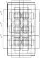
ここで、提案領域計算部14(候補領域・スコア計算部141及び候補領域選択部142)は、「アンカー」(anchor)と呼ばれる入力画像に固定的に配置された基準領域を用いて、proposed regionsを推定する。例えば、提案領域計算部14は、feature mapsに基づいて、各アンカーの領域又は複数のアンカーの組み合わせにより形成される領域における物体の有無、物体が存在する領域のサイズ、並びに、上述したスコアを推定してよい。 Here, the proposed area calculation unit 14 (candidate area /
図4に示すように、1組のアンカー群143は、例示的に、中心位置(基準中心位置)を共通とするK=9個のアンカーにより形成されてよい。一実施形態では、図5に例示するように、当該1組のアンカー群143が或る間隔(デフォルト値として例えば16ピクセル)で画像144全体に配置される。例えば、高さ:600×幅:800[ピクセル]の画像144の場合、画像144には、H(高さ方向の分割数;例えば38)×W(幅方向の分割数;例えば50)で示される各位置を基準中心位置とするアンカーが、それぞれの位置に9個ずつ配置される。このように、提案領域計算部14はH×W×K個のアンカーを用いてよい。なお、図5の例では、図の簡略化のため、H:2、W:3、K:9としたアンカーの例を示している。 As shown in FIG. 4, one set of
なお、図4及び図5の例では、アンカーとして矩形の領域が用いられているが、これに限定されるものではなく、楕円等の種々の形状が用いられてもよい。 In the examples of FIGS. 4 and 5, a rectangular area is used as an anchor, but the anchor is not limited to this, and various shapes such as an ellipse may be used.
RPN層140、NMS処理、及びアンカーを用いたproposed regionsの推定手法は、既知の種々の手法により実現可能であるため、これらの詳細については説明を省略する。 Since the estimation method of promoted regions using the
物体位置・種類推定部15は、CNN層130から得られるfeature mapsと、RPN層140から得られるproposed regionsとをFast R−CNN層150(図6参照)に入力する。そして、物体位置・種類推定部15は、入力された情報に基づいて、proposed regionsをより高精度に分析するとともに、物体の種類を推定する。 The object position /
Fast R−CNN層150は、複数の処理層を有するNNの一例である。Fast R−CNN層150は、図6に例示するように、feature maps及びproposed regionsに基づき、画像領域のどこの矩形領域にどの種類の物体が存在するかをスコア付きで示した推定結果を出力する。推定結果は、detected regionsと称されてもよい。なお、物体の種類は、NNに学習させることで決定されてよい。Fast R−CNN層150から出力された推定結果は、推定結果選択部16に入力される。なお、推定結果とともに、RPN層140からのproposed regionsが物体位置・種類推定部15から推定結果選択部16に入力されてもよい。 The Fast R-
図6の例では、Fast R−CNN層150への入力データとして、特徴マップ計算部13で抽出された高さ38ピクセル、幅50ピクセル、512チャネルのfeature mapsが入力されるものとする。また、Fast R−CNN層150への入力データとして、提案領域計算部14で計算された、スコアを含むproposed regions付きの入力画像が入力されるものとする。 In the example of FIG. 6, it is assumed that the feature maps with a height of 38 pixels and a width of 50 pixels and 512 channels extracted by the feature
Fast R−CNN層150は、例えば、上述した入力データに対して、推定結果付きの入力画像を出力してよい。なお、Fast R−CNN層150から出力されるデータは、入力画像を含まない推定結果の情報に限定されてもよい。 The Fast R-
図6の例では、推定結果付き入力画像は、スコアとアンカーに対する位置関係とに応じて、RPN層140からのproposed regionsよりも絞り込まれたproposed regionsが示されている。また、推定結果付き入力画像は、proposed regionsに対して、推定された物体の種類(例えば、“Person”、“Horse”、“Dog”等)がスコアとともに示されている。 In the example of FIG. 6, the input image with the estimation result shows the produced regions that are narrowed down more than the produced regions from the
なお、Fast R−CNN層150は、既知の種々の手法により実現可能であるため、その詳細については説明を省略する。 Since the Fast R-
以上のように、特徴マップ計算部13、提案領域計算部14、及び、物体位置・種類推定部15は、画像系列内の第1画像について、第1画像内において物体の存在が推定される候補領域及び当該候補領域における物体の存在の可能性を示す指標の組を、第1画像の画像特徴量に従い複数推定する推定部の一例である。 As described above, the feature
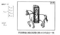
推定結果選択部16は、図7に例示するように、物体位置・種類推定部15から入力された推定結果付き入力画像に基づき、推定結果から物体の種類ごとの位置を取得し、取得の結果として、物体の位置・種類の認識結果付き入力画像を出力する。なお、推定結果選択部16は、取得の処理において、RPN層140から出力されるproposed regionsの情報を用いてもよい。推定結果選択部16から出力された認識結果付き入力画像は、認識結果171としてメモリ部17に格納され蓄積される。 As illustrated in FIG. 7, the estimation
なお、推定結果選択部16は、例えば、上述した推定結果或いは推定結果付き入力画像に基づき、入力画像を含まない認識結果の情報を出力してもよい。 The estimation
推定結果選択部16は、提案領域計算部14と同様に、スコアの高い順に重なりの少ない領域を選択していくNMS処理等を実行してよい。 Similar to the proposed
以上のように、推定結果選択部16は、推定した複数の組における候補領域及び指標を用いて第1画像における物体の位置を決定する処理部の一例である。 As described above, the estimation
上述した特徴マップ計算部13、提案領域計算部14、物体位置・種類推定部15、及び推定結果選択部16は、Faster R−CNNとして機能する。Faster R−CNNによれば、入力画像のどの矩形領域に、NNに学習させた種類のうちのどの種類の物体が存在するかを、トレーニングデータを用いて学習させたNNの重みを用いて高速に認識(検出)することができる。 The feature
ここで、推定結果選択部16は、物体位置・種類推定部15から入力される推定結果(或いは推定結果付き入力画像)を分析し、分析結果に基づいて、次のフレーム以降のFaster R−CNNにおける物体の位置・種類の推定精度を向上させる。換言すれば、推定結果選択部16は、過去のフレームの推定結果(或いは推定結果付き入力画像)を分析し、分析結果に基づいて、現在の入力画像についてのFaster R−CNNにおける物体の位置・種類の推定精度を向上させる。このため、推定結果選択部16は、過去数フレームに亘る推定結果、或いは、推定結果の分析結果を記憶し蓄積する記憶部を有してよい。当該記憶部は、検出装置1が有するメモリ又は記憶装置の記憶領域の少なくとも一部により実現されてよい。 Here, the estimation
一例として、推定結果選択部16は、過去のフレームのdetected regionsに基づいて、現在のフレームにおける物体の移動位置を示す移動情報を算出してよい。そして、推定結果選択部16は、算出した移動情報に基づいて、Faster R−CNNの処理、例えば、後述する、推定結果の絞り込み処理、又は、推定結果の重み付け平均を算出する処理、を行なってよい。なお、移動情報は、現在のフレームにおける、過去のフレームの推定結果から予測された物体の位置に関する情報である。 As an example, the estimation
移動情報の第1の例としては、物体位置・種類推定部15から出力されるdetected regionsのうちの、予測領域に近い(例えば重なりが大きい)detected regionsのスコアを高くする補正情報が挙げられる。補正情報としては、例えば、detected regionsの補正後のスコアそのものであってもよいし、当該スコアを、他のproposed regionsのスコアよりも高くするような重み付けのための係数等であってもよい。 As a first example of the movement information, there is correction information for increasing the score of the detected regions that are close to the prediction region (for example, have a large overlap) among the detected regions output from the object position /
なお、予測領域は、現在のフレームにおいて予測された物体の位置を表す領域であり、detected regionsと同様のデータ構造であってよい。 The predicted area is an area representing the predicted position of the object in the current frame, and may have the same data structure as the detected regions.
第1の例の場合、移動情報は、推定結果選択部16においてスコアの高い順に重なりの少ない領域を選択していくNMS処理等への入力とされてよい。 In the case of the first example, the movement information may be input to the NMS process or the like in which the estimation
なお、第1の例における移動情報には、例えば、上述した補正情報に代えて、予測領域と、当該予測領域のスコアを高くする補正情報とが含まれてもよい。 The movement information in the first example may include, for example, a prediction region and correction information for increasing the score of the prediction region, instead of the correction information described above.
また、移動情報の第2の例としては、物体位置・種類推定部15から出力されるdetected regionsのうちの、予測領域に近い(例えば重なりが大きい)detected regionsの重み付き平均を算出するための情報が挙げられる。重み付き平均を算出するための情報としては、例えば、以下の少なくとも1種類の情報が挙げられる。換言すれば、第2の例に係る移動情報は、次に入力される入力画像に係る重み付き平均を算出する処理の処理対象である複数の候補領域の各々の重み情報であるといえる。 Further, as a second example of the movement information, among the detected regions output from the object position /
・予測領域とdetected regionsとの距離
・マハラノビス距離(後述)
・detected regionsのスコア
・追尾の尤度・ Distance between predicted area and detected regions ・ Mahalanobis distance (described later)
・ Score of detected regions ・ Probability of tracking
第2の例の場合、移動情報は、推定結果選択部16において予測領域に近い(例えば重なりが大きい)detected regionsの重み付き平均を算出する処理への入力とされてよい。 In the case of the second example, the movement information may be input to the process of calculating the weighted average of the detected regions close to the prediction region (for example, having a large overlap) in the estimation
なお、推定結果選択部16は、第2の例においても、移動情報が発生していない場合には、そのときのフレームの処理においてNMS処理により推定結果を取得してよい。すなわち、推定結果選択部16は、移動情報に応じて、NMS処理、及び、候補領域の重み付き平均の計算処理、を切り替えてよい。 Even in the second example, the estimation
以上のように、推定結果選択部16(スコア補正部161(図1参照))は、画像系列から物体の移動に関する移動情報を取得する取得部の一例である。例えば、推定結果選択部16は、画像系列内の第1画像よりも時間的に過去の複数の画像の各々について当該画像ごとに決定した物体の位置に基づき同一物体と認識される物体の位置の時間的な変化に基づいて、移動情報を取得するといえる。そして、処理部の一例としての推定結果選択部16は、推定した複数の組における候補領域及び指標を用いて第1画像における物体の位置を決定する場合に、取得した移動情報に基づき、推定した複数の組における候補領域及び指標に対する補正処理を施すのである。 As described above, the estimation result selection unit 16 (score correction unit 161 (see FIG. 1)) is an example of an acquisition unit that acquires movement information regarding the movement of an object from an image series. For example, the estimation
このように、推定結果選択部16によれば、動画内を移動する物体の予測領域(例えば矩形領域)を過去の画像系列データから推定し、Faster R−CNN内部の処理に用いることができる。これにより、ニューラルネットワークを用いた物体の位置の検出処理において、物体の位置の検出精度を向上させることができる。 As described above, according to the estimation
ここで、上述のように、Faster R−CNNの計算は、静止画を対象としている。換言すれば、Faster R−CNNは本来静止画を対象とした物体検出(Object Detection)のためのNNとして提案された手法である。 Here, as described above, the calculation of Faster R-CNN targets still images. In other words, Faster R-CNN is a method originally proposed as an NN for object detection targeting still images.
このため、例えば、上述した関連する技術(各静止画で特定した物体の検出位置により物体の動きを追尾する手法)において、移動する人物を追尾対象とした場合、Faster R−CNNは追尾処理とは独立した処理として実行される。すなわち、Faster R−CNNを用いた物体検出(Object Detection)においては、Faster R−CNNの処理の内部で、追尾処理によって得られる計算結果は用いられていない。 Therefore, for example, in the above-mentioned related technology (a method of tracking the movement of an object according to the detection position of the object specified in each still image), when a moving person is targeted for tracking, the Faster R-CNN is a tracking process. Is executed as an independent process. That is, in the object detection using the Faster R-CNN, the calculation result obtained by the tracking process is not used inside the process of the Faster R-CNN.
具体的に、上述した関連する技術では、Faster R−CNNにより、「歩行者」と「歩行者の位置(例えば矩形領域)」とを繰り返し推定する処理と、得られた推定結果をベースにトラッキングを行なう処理とが行なわれる。しかし、Faster R−CNN内部の処理は変更されていない。 Specifically, in the related technology described above, the process of repeatedly estimating the "pedestrian" and the "pedestrian position (for example, a rectangular area)" by the Faster R-CNN and the tracking based on the obtained estimation result. Is performed. However, the processing inside Faster R-CNN has not changed.
これに対し、推定結果選択部16は、Faster R−CNN内部の処理に、物体の運動から推定可能な予測領域の情報を活用させること、換言すれば、トラッキングの結果を利用させることで、物体検出及び追尾の精度を高めることができる。すなわち、推定結果選択部16は、重なりをもつ物体の種類及び位置の推定結果を絞り込む或いは重み付き平均をとるために、予測領域の情報を用いるのである。 On the other hand, the estimation
このように、静止画の情報と移動物体追尾による予測領域の情報とは質的に異なる情報であり、この質的に異なる情報をFaster R−CNNの内部の処理に用いることで、動画を対象とした物体検出の精度を高めることができる。 In this way, the information of the still image and the information of the prediction area by tracking the moving object are qualitatively different information, and by using this qualitatively different information for the internal processing of the Faster R-CNN, the moving image is targeted. It is possible to improve the accuracy of object detection.
また、NNにおいて、物体検出のための学習データのラベル付けには多くの手間が必要になる。これに対し、推定結果選択部16により、Faster R−CNNでは、フレーム間で移動する物体が同一の物体であることを認識できる。従って、例えば、学習データのラベルとして、フレーム間で連続性を有する物体に対して同一のラベル(例えば物体の種類等)を付加することができる。 Further, in NN, labeling training data for object detection requires a lot of time and effort. On the other hand, the estimation
さらに、例えば、或るフレームにおいて、物体が障害物(例えば木)の後ろ等に入り、一部が隠れた場合であっても、推定結果選択部16は、過去の認識結果から推定される物体の位置や種類の情報を用いることで予測領域を推定できる。これにより、静止画ではproposed regionsとして提案されてこなかった領域が、移動情報を用いた予測領域として提案されるため、移動物体を認識できる。 Further, for example, even when an object enters behind an obstacle (for example, a tree) in a certain frame and a part of the object is hidden, the estimation
また、遠くの方に遠ざかり、粗い画素の情報でしか表現されなくなった物体にも、予測領域の情報を用いることで、Faster R−CNNの認識精度を高めることができる。 Further, the recognition accuracy of the Faster R-CNN can be improved by using the information in the prediction region even for an object that is far away and can be expressed only by the information of coarse pixels.
さらに、上述した検出装置1では、推定結果選択部16により、近いスコアの領域が重なった領域からNMS処理を用い、スコア順に領域を選択しながら、選択済みの領域と重なりの大きな領域を選択対象から外していく処理が実行される。 Further, in the
このとき、ほとんどスコアの変わらない複数の領域が重なっていることがある。この場合において、非常にスコアが近く、領域が重なったproposed regionsのうちの、例えばスコア0.995の領域と0.99の領域とは、偶然これらのスコアになっただけという場合がある。例えば、実際にはこれらのスコアが逆である場合のほうが正解に近い場合も起こり得る。一例として、学習済みのニューラルネットワークが出力する各検出領域のスコアは、認識画像、学習画像、ネットワーク構成、学習済みの重みの大きさ等により、偶然このようなスコアになる場合がある。 At this time, a plurality of areas with almost the same score may overlap. In this case, among the promoted regions where the scores are very close and the regions overlap, for example, the region with a score of 0.995 and the region with a score of 0.99 may only accidentally reach these scores. For example, in reality, it may happen that the opposite of these scores is closer to the correct answer. As an example, the score of each detection region output by the trained neural network may accidentally become such a score depending on the recognition image, the trained image, the network configuration, the size of the trained weight, and the like.
また、領域に割り当てられたスコア情報以外に、アンカーの配置(アンカー中心位置の配置や予め用意した9つのアンカー)により、偶然、検出したい物体の候補領域が候補に上がってこないようなことも起こり得る。 In addition to the score information assigned to the area, the candidate area of the object to be detected may not come up as a candidate by chance due to the arrangement of the anchors (the arrangement of the anchor center position and the nine anchors prepared in advance). obtain.
以上のような場合であっても、推定結果選択部16によれば、静止画レベルでFaster R−CNNの処理を各フレームで独立して実行するだけでなく、移動物体の過去の存在領域の情報から推定される最新フレームにおける予測領域の情報を併用できる。従って、物体検出及び追尾の精度を高めることができる。 Even in the above cases, according to the estimation
〔1−2〕推定結果選択部の説明
以下、推定結果選択部16の詳細について説明する。[1-2] Description of the estimation result selection unit The details of the estimation
上述のように、推定結果選択部16は、動画内を移動する物体の予測領域を、過去の画像系列データから推定し、Faster R−CNN内部の処理に用いることで、Faster R−CNNによる物体の種類や位置の推定精度を向上させる。 As described above, the estimation
図1に示すように、推定結果選択部16は、例示的に、スコア補正部161及び取得部162をそなえてよい。 As shown in FIG. 1, the estimation
スコア補正部161は、過去のフレームにおけるFaster R−CNNでの認識結果に基づき、最新のフレームにおける物体の予測領域(「予測存在領域」と称されてもよい)を推定し、予測領域に基づき移動情報を算出する。例えば、スコア補正部161は、後述するように、予測存在領域の推定とともに、スコア、又は、重み付き平均の算出のための情報を取得してよい。 The
スコア補正部161が算出した移動情報は、Faster R−CNNへの入力として、取得部162に与えられてよい。 The movement information calculated by the
予測存在領域は、例えば、物体の予測存在位置(x,y)及び存在領域(w,h)を結合した(x,y,w,h)によって表されてよい。なお、xは画像内の縦方向(第1方向)における矩形領域の代表点(例えば中心点)の位置、yは画像内の横方向(第1方向に直交する第2方向)における矩形領域の代表点の位置を示す。また、wは矩形領域の縦方向(第1方向)の幅(長さ)、hは矩形領域の横方向(第2方向)の高さ(長さ)を示す。 The predicted existence region may be represented by, for example, (x, y, w, h) in which the predicted existence position (x, y) and the existence region (w, h) of the object are combined. Note that x is the position of the representative point (for example, the center point) of the rectangular region in the vertical direction (first direction) in the image, and y is the position of the rectangular region in the horizontal direction (second direction orthogonal to the first direction) in the image. Indicates the position of the representative point. Further, w indicates the width (length) of the rectangular region in the vertical direction (first direction), and h indicates the height (length) of the rectangular region in the horizontal direction (second direction).
スコア補正部161は、図8に例示するように、大きさが変化するような移動物体の検出及びトラッキングにおいて、過去の画像系列データから、Kalman Filter等の追尾フィルタを用いて、物体の予測存在領域を推定してよい。物体の予測存在領域は、フレーム毎かつ対象物体毎のベクトルSを算出することで推定されてよい。 As illustrated in FIG. 8, the
なお、スコア補正部161は、矩形領域以外の領域パラメータを推定することも可能である。換言すれば、スコア補正部161は、検出装置1において矩形領域以外(例えば楕円形状)のアンカーが用いられる場合、アンカーの形状に応じた予測存在領域を推定できる。以下の説明では、アンカーの形状が矩形であるものとする。 The
スコア補正部161は、例えば、1度目に通常のFaster R−CNNによって推定された矩形領域の位置と大きさ、物体の種類(人、車、馬等)、観測時のフレームレート等に基づき、次にその物体が検出され得る矩形領域を定めてよい。そして、スコア補正部161は、定めた矩形領域内で認識された同じ種類の対象物体を、前フレームで認識された物体と同じ物体であると推定してよい。 The
このように、スコア補正部161は、フレーム毎に対象物体を特定し、対象物体毎に、予め用意した運動モデルに当て嵌めることで、ベクトルSを求め、予測存在領域を推定してよい。運動モデルとしては、等速運動モデルや加速度運動モデル等の種々の運動モデルが挙げられる。 In this way, the
なお、物体の予測存在領域の推定には、運動モデルに代えて、画像のピクセル値の相関を取る等の他の手法が用いられてもよい。また、MHT(Multiple Hypothesis Tracking)等のような、追尾物体と検出物体との対応付けを行なうデータアソシエーション(Data Association)による未観測状態を考慮した追尾モデルが用いられてもよい。 In addition, in order to estimate the predicted existence region of the object, another method such as correlating the pixel values of the image may be used instead of the motion model. Further, a tracking model such as MHT (Multiple Hypothesis Tracking) that considers an unobserved state by a data association that associates a tracking object with a detected object may be used.
スコア補正部161による物体の予測存在領域の推定の詳細については後述する。 The details of the estimation of the predicted existence area of the object by the
スコア補正部161は、推定した予測存在領域に基づいて、移動情報を算出してよい。 The
取得部162は、スコア補正部161が算出した移動情報に基づいて、認識結果171を出力する。取得部162による認識結果171の出力処理は、上述した移動情報の第1及び第2の例に応じて、以下のように実施されてよい。なお、以下の例において、図9及び図11では、メモリ部11及び17の図示を省略している。 The
(第1の例)
取得部162は、図9及び図10に例示するように、スコア補正部161が例えばt=2のときにt=1及びt=2の移動物体の位置情報等に基づき推定したt=3の予測存在領域の情報を、t=3のときに利用してよい。例えば、取得部162は、NMS処理の機能を有してよく、NMS処理実行前の矩形領域のスコアを予測存在領域からの矩形領域の距離に応じて変更する補正情報を入力として、当該NMS処理を実行してよい。NMS処理の実行結果は、認識結果171(図1参照)として出力されてよい。(First example)
As illustrated in FIGS. 9 and 10, the
一例として、図10に示すように、取得部162は、t=3の予測領域の位置・大きさに近い矩形領域(detected regions)のスコアを高くする補正情報を入力としてよい。予測領域の位置・大きさに近いdetected regionsとしては、例えば、矩形領域のうちの予測領域と重なる領域の割合pが最大の矩形領域(図10の例では矩形領域A)が選択されてよい。このとき、取得部162は、例えば、pが最大の矩形領域Aのスコアに(1.0+p)を乗じることで、矩形領域Aのスコアを補正してよい。(1.0+p)は補正情報の一例である。 As an example, as shown in FIG. 10, the
以上のように、取得部162は、複数の組の各々の指標に基づき複数の組を所定数の組に絞り込む処理を行なうといえる。 As described above, it can be said that the
(第2の例)
また、取得部162は、図11に例示するように、スコア補正部161が例えばt=2のときにt=1及びt=2の移動物体の位置情報等に基づき推定したt=3の予測存在領域の情報を、t=3のときに利用してよい。例えば、取得部162は、NMS処理等の機能とともに、detected regionsの重み付き平均を算出する機能を有してよい。取得部162は、スコア補正部161から入力される重み付き平均を算出するための情報に基づいて、detected regionsの重み付き平均を算出してよい。算出された重み付き平均は、認識結果171(図1参照)として出力されてよい。(Second example)
Further, as illustrated in FIG. 11, the
なお、図11の例において、t=1又はt=2のときのフレームでは、取得部162は、第1の例と同様に、NMS処理により認識結果171を出力してよい。 In the example of FIG. 11, in the frame when t = 1 or t = 2, the
このように、取得部162は、複数の組の各々の指標に基づき複数の組の複数の候補領域の重み付き平均を算出する処理を行なうといえる。 As described above, it can be said that the
以上のように、推定結果選択部16により、物体検出の認識精度を高めることができる。なお、推定結果選択部16によりメモリ部17に格納される認識結果171は、Faster R−CNNにおけるラベル付き学習データとして利用されてもよい。 As described above, the estimation
上述のように、Faster R−CNNでは、物体の位置や種類の推定において、限られた数のアンカー位置を基準とするproposed regionsが利用される。proposed regionsの推定の手法は、経験則に基づく独特なものである。例えば、proposed regionsは、予め指定したサイズやアスペクト比のアンカーをあるピクセル間隔で配置し、これらのアンカー基準位置に静止画を入力としNNを用いて計算される補正値を加算することで推定される。 As mentioned above, Faster R-CNN utilizes produced regions based on a limited number of anchor positions in estimating the position and type of an object. The method of estimating produced regions is unique based on empirical rules. For example, promoted regions are estimated by arranging anchors of a predetermined size and aspect ratio at certain pixel intervals, inputting a still image to these anchor reference positions, and adding a correction value calculated using NN. NS.
上記の手法による物体候補領域(proposed regions)の計算には、静止画の情報のみが用いられている。これに対し、一実施形態に係る検出装置1は、静止画の情報とは質的に異なる情報である、物体の運動から予測される物体候補領域(位置、高さ、幅)に基づく移動情報を利用することで、物体検知の精度を向上させることができる。 Only the information of the still image is used for the calculation of the object candidate regions (proposed regions) by the above method. On the other hand, the
図12は、海辺に6艘〜10艘ほどの船(boat)が浮かぶ画像において、Faster R−CNNに移動情報を追加する前後の認識結果の一例を示す図である。なお、図12では、物体位置・種類推定部15から出力されるdetected regionsについて、移動情報の一例としてのスコアの補正情報(例えば、実際にboatが存在しそうな矩形領域のスコアを高くするような補正情報)に基づき評価した例を示している。 FIG. 12 is a diagram showing an example of recognition results before and after adding movement information to the Faster R-CNN in an image in which about 6 to 10 boats float on the beach. In addition, in FIG. 12, regarding the directed regions output from the object position /
これにより、適切なスコアの補正が行なわれた領域で、新たに高スコアでboatが検出されるようになった(図12の右側参照)。Faster R−CNNに移動情報の一例としての重み付き平均の算出のための情報が与えられる場合にも、図12に示す例と同様の効果が得られることが期待できる。 As a result, boats are newly detected with a high score in the area where the appropriate score is corrected (see the right side of FIG. 12). Even when the information for calculating the weighted average as an example of the movement information is given to the Faster R-CNN, it can be expected that the same effect as the example shown in FIG. 12 can be obtained.
〔1−3〕動作例
次に、上述の如く構成された検出装置1の動作例を説明する。[1-3] Operation example Next, an operation example of the
(第1の例)
第1の例では、図13に例示するように、検出装置1においては、メモリ部11に記憶された画像データ111(例えば画像系列のデータ)から、1つの入力画像(例えば1フレーム)が取得される(ステップS1)。(First example)
In the first example, as illustrated in FIG. 13, in the
画像前処理部12は、入力画像に対して前処理を行なう(ステップS2)。前処理には、入力画像を後段の処理に適した画像に変更するためのサイズ変更、ピクセル値変更、輝度補正等が含まれてよい。 The
画像前処理部12は、前処理後の入力画像を特徴マップ計算部13に入力する(ステップS3)。特徴マップ計算部13では、CNN層130からfeature mapsが出力される(ステップS4)。 The
特徴マップ計算部13は、feature mapsを提案領域計算部14に入力する(ステップS5)。提案領域計算部14では、RPN層140からproposed regionsが出力される(ステップS6)。 The feature
次いで、特徴マップ計算部13からのfeature mapsと提案領域計算部14からのproposed regionsとが物体位置・種類推定部15に入力される(ステップS7)。そして、処理がステップS8に移行する。 Next, the feature maps from the feature
ステップS8において、物体位置・種類推定部15では、Fast R−CNN層150から物体の位置・種類の推定結果(detected regions)が出力される。 In step S8, the object position /
推定結果選択部16は、移動情報の発生有無を判定し(ステップS9)、移動情報が発生していない場合(ステップS9でNo)、処理がステップS11に移行する。なお、移動情報が発生していない場合としては、例示的に、過去の入力画像が存在しない場合(例えば図9に示すt=1又はt=2の場合)が挙げられる。或いは、移動情報が発生していない場合として、予測領域が認識されなかった場合(例えば過去の入力画像に物体が存在しなかった場合)等も挙げられる。 The estimation
移動情報が発生している場合(ステップS9でYes)、スコア補正処理を行ない(ステップS10)、処理がステップS11に移行する。 When the movement information is generated (Yes in step S9), the score correction process is performed (step S10), and the process shifts to step S11.
ステップS11では、推定結果選択部16の取得部162は、物体位置・種類推定部15からの推定結果に基づき物体の種類ごとの位置を絞り込み、絞り込みの結果として、物体の位置・種類の認識結果を出力する。このとき、ステップS10でスコアが補正されている場合には、補正後のスコアに基づいて物体の種類ごとの位置の絞り込みが行なわれる。 In step S11, the
以上により、ステップS1で入力された1つの入力画像(例えば1フレーム)に対する処理が終了する。 As a result, the processing for one input image (for example, one frame) input in step S1 is completed.
ステップS10のスコア補正処理では、図14に例示するように、推定結果選択部16のスコア補正部161は、過去の入力画像に対する認識結果に基づき、物体の予測存在領域を推定する(ステップS21)。 In the score correction process of step S10, as illustrated in FIG. 14, the
次いで、スコア補正部161は、推定した予測存在領域に近いdetected regionsのスコアを高くするような補正情報を算出する(ステップS22)。なお、補正情報は、予測領域に近い(例えば重なりが大きい)proposed regionsのスコアを高くする情報であってよい。補正情報としては、例えば、proposed regionsの補正後のスコアそのものであってもよいし、当該スコアを、他のproposed regionsのスコアよりも高くするような重み付けのための係数等であってもよい。 Next, the
そして、スコア補正部161は、補正情報に基づき、detected regionsのスコアを補正し(ステップS23)、処理が終了する。 Then, the
なお、ステップS21の物体の予測存在領域の推定処理の詳細は、後述する。 The details of the estimation process of the predicted existence region of the object in step S21 will be described later.
(第2の例)
第2の例では、図15に例示するように、ステップS1〜S9の処理は図13に示す第1の例と同様である。(Second example)
In the second example, as illustrated in FIG. 15, the processing of steps S1 to S9 is the same as that of the first example shown in FIG.
ステップS8において、物体位置・種類推定部15が推定結果を推定結果選択部16に入力する際に、移動情報の発生有無に応じて、処理が分岐する(ステップS9)。 In step S8, when the object position /
移動情報が発生していない場合(ステップS9でNo)、処理がステップS11に移行する。なお、移動情報が発生していない場合としては、例示的に、過去の入力画像が存在しない場合(例えば図9に示すt=1又はt=2の場合)が挙げられる。或いは、移動情報が発生していない場合として、予測領域が認識されなかった場合(例えば過去の入力画像に物体が存在しなかった場合)等も挙げられる。 If no movement information has been generated (No in step S9), the process proceeds to step S11. As an example, the case where the movement information is not generated includes the case where the past input image does not exist (for example, the case where t = 1 or t = 2 shown in FIG. 9). Alternatively, as a case where movement information is not generated, a case where the prediction area is not recognized (for example, a case where an object does not exist in the past input image) may be mentioned.
ステップS11では、推定結果選択部16の取得部162は、物体位置・種類推定部15からの推定結果に基づき物体の種類ごとの位置を絞り込み、絞り込みの結果として、物体の位置・種類の認識結果を出力する。 In step S11, the
以上により、ステップS1で入力された1つの入力画像(例えば1フレーム)に対する処理が終了する。 As a result, the processing for one input image (for example, one frame) input in step S1 is completed.
一方、移動情報が発生している場合(ステップS9でYes)、推定結果選択部16は、重み付き平均の算出に用いる情報の取得処理を行ない(ステップS12)、処理がステップS13に移行する。 On the other hand, when the movement information is generated (Yes in step S9), the estimation
ステップS13では、推定結果選択部16の取得部162は、物体位置・種類推定部15からの推定結果に基づき重み付き平均を算出し、認識結果を出力する。 In step S13, the
以上により、ステップS1で入力された1つの入力画像(例えば1フレーム)に対する処理が終了する。 As a result, the processing for one input image (for example, one frame) input in step S1 is completed.
重み付き平均の算出に用いる情報の取得処理では、図16に例示するように、推定結果選択部16のスコア補正部161は、過去の入力画像に対する認識結果に基づき、物体の予測存在領域を推定する(ステップS21)。 In the information acquisition process used for calculating the weighted average, as illustrated in FIG. 16, the
そして、推定結果選択部16のスコア補正部161は、推定した予測存在領域に基づく移動情報を取得部162に出力し(ステップS24)、処理が終了する。例えば、スコア補正部161は、移動情報として、推定した予測存在領域に近いdetected regionsのスコアの重み付き平均を算出するための以下の1以上の種類の情報を算出してよい。 Then, the
・予測領域とdetected regionsとの距離
・マハラノビス距離(後述)
・detected regionsのスコア
・追尾の尤度・ Distance between predicted area and detected regions ・ Mahalanobis distance (described later)
・ Score of detected regions ・ Likelihood of tracking
なお、ステップS21の物体の予測存在領域の推定処理の詳細は、後述する。 The details of the estimation process of the predicted existence region of the object in step S21 will be described later.
〔1−4〕予測存在領域の推定処理の説明
次に、推定結果選択部16による物体の予測存在領域の推定処理について説明する。推定結果選択部16のスコア補正部161は、推定処理において、以下の手法のうちのいずれか1つ、又は、2つ以上の組み合わせにより、予測存在領域を推定してよい。[1-4] Description of Predicted Existence Area Estimation Processing Next, the estimation process of the predicted existence area of the object by the estimation
(第1の手法)
はじめに、第1の手法の一例について説明する。(First method)
First, an example of the first method will be described.
図17の左側に例示するように、t=t0において、Faster R−CNNにより、矩形領域として、物体の一例である犬が存在する領域s(t0)=(x(t0),y(t0),w(t0),h(t0))が検出された場合を想定する。なお、(x(t0),y(t0))は検出領域の中心位置、(w(t0),h(t0))は検出領域の幅及び高さであるものとする。なお、tは画像データ111の画像系列における時刻(タイミング)を特定する値であり、以下の例では、フレームに対応するものとする。As illustrated on the left side of FIG. 17, at t = t0, the region s (t 0 ) = (x (t0 ), y) in which a dog, which is an example of an object, exists as a rectangular region by the Faster R-CNN. It is assumed that (t0 ), w (t0 ), h (t0 )) is detected. It is assumed that (x (t0 ), y (t0 )) is the center position of the detection area, and (w (t0 ), h (t0 )) is the width and height of the detection area. Note that t is a value that specifies the time (timing) in the image series of the
また、図17の左側に例示する犬がt=t0+1において検出され得る領域は、t=t0で検出されたs(t0)=(x(t0),y(t0),w(t0),h(t0))を中心とする、或る範囲の領域に限定されるものと仮定する。Further, the region in which the dog illustrated on the left side of FIG. 17 can be detected att = t 0 + 1 is s (t0 ) = (x (t0 ), y (t0 ),detected at t = t 0. It is assumed that it is limited to a certain range of regions centered on w (t0 ), h (t0)).
例えば、図17の右側に示すように、t=t0+1において犬が検出された場合を想定する。なお、t=t0+1のときの検出領域を、s(t0+1)=(x(t0+1),y(t0+1),w(t0+1),h(t0+1))と表記する。For example, as shown on the right side of FIG. 17, it is assumed that a dog is detected att = t 0 + 1. The detection area when t = t0 + 1 is defined as s (t0 + 1) = (x (t0 + 1), y (t0 + 1), w (t0 + 1), h (t0 + 1)). Notated as.
このとき、スコア補正部161は、(Δx,Δy,Δw,Δh)=s(t0+1)−s(t0)の値が、予め定めた或る範囲の大きさ以下であれば、t=t0+1で検出された犬は、前フレーム(t=t0)で検出された犬と同じ犬であると判定してよい。At this time, if the value of (Δx, Δy, Δw, Δh) = s (t0 + 1) −s (t0 ) is equal to or less than a predetermined range, the score correction unit 161 t. The dog detected at = t0 + 1 may be determined to be the same dog as the dog detected at the previous frame (t = t0).
或るフレームで検出された物体が前フレームで検出された物体と同一であるか否かを判定するための手法として、以下の(a)〜(c)のいずれか、或いは、(a)〜(c)の2つ以上の組み合わせが用いられてよい。 As a method for determining whether or not the object detected in a certain frame is the same as the object detected in the previous frame, any one of the following (a) to (c), or (a) to Two or more combinations of (c) may be used.
(a)例えば、スコア補正部161は、(Δx2+Δy2)1/2<rのように中心位置が可変な範囲rを定め、|Δw|<Δw_max,|Δh|<Δh_maxのように領域の幅及び高さが可変な範囲を定めてよい。なお、rの値、Δw_max、Δh_maxの値は、検出された物体の種類、観測時のフレームレート、検出された矩形領域の大きさ(w,h)等に基づき調節可能な値であってよい。或いは、rの値、Δw_max、Δh_maxの値は、所定のルールに従う固定値であってもよい。(A) For example, the
(b)また、スコア補正部161は、或るフレームにおける物体の検出領域と前フレームにおける物体の検出領域との重なりの大きさをIoU(Intersection of Union)値で評価し、IoU値が或る閾値以上であれば同じ物体であると判定してもよい。 (B) Further, the
(c)或いは、スコア補正部161は、t=t0で検出された領域とt=t0+1で検出された領域とのピクセル値の相関値を用いてもよい。(C) or, the
スコア補正部161は、t=t0で検出された犬とt=t0+1で検出された犬とが同じ犬であると判定した場合、t=t0及びt=t0+1でそれぞれ検出した(x,y,w,h)の値に基づき、x,y,w,hの時間変化ds/dtを求めてよい。ここで、時間変化ds/dt=(dx/dt,dy/dt,dw/dt,dh/dt)である。
また、スコア補正部161は、t=t0+2の場合、上記で求めたds/dtの値を用いて、s(t=t0+2|t0+1)=s(t0+1)+ds/dt×Δtにより、時刻t=t0+2における予測領域s(t0+2|t0+1)の値を推定してよい。なお、Δtはフレーム間の時間間隔である。ここで、予測領域s(t0+2|t0+1)=(x(t0+2|t0+1),y(t0+2|t0+1),w(t0+2|t0+1),h(t0+2|t0+1))である。Further, in the case of t = t 0 + 2, the
スコア補正部161は、上記により得られた予測領域の値に基づいて、Faster R−CNN(取得部162)に移動情報を出力してよい。 The
なお、t=t3の場合における予測領域の値は、上述した時刻t=t0,t0+1,t0+2を時刻t=t0+1,t0+2,t0+3に置き換えることで推定されてよい。t=t4以降も同様である。The value of the prediction region in the case of t = t3 is estimated by replacingthe above-mentioned time t = t 0 , t0 + 1, t0 + 2 with the time t = t0 + 1, t0 + 2, t0 + 3. May be done.t = t4 or later is also similar.
(第2の手法)
次に、第2の手法の一例について説明する。第2の手法では、カルマンフィルタ(Kalman Filter)等速運動モデルを用いて予測領域を推定する一例について説明する。(Second method)
Next, an example of the second method will be described. In the second method, an example of estimating the prediction region using the Kalman Filter constant velocity motion model will be described.
例えば、カルマンフィルタ等速運動モデルは、図18に例示する状態ベクトルxc,i,kを有してよい。なお、状態ベクトルにおけるcは追尾物体の種類、iは追尾物体の識別情報(例えば番号)、kは時刻(例えばフレーム番号)である。For example, the Kalman filter constant velocity motion model may havethe state vectors x c, i, k illustrated in FIG. In the state vector, c is the type of the tracking object, i is the identification information (for example, number) of the tracking object, and k is the time (for example, the frame number).
スコア補正部161は、図18に例示するように、追尾対象ごとに、物体の種類c、存在領域(x,y,w,h)及びその速度(x(ドット),y(ドット),w(ドット),h(ドット))を並べた状態ベクトルxc,i,kを保持してよい。スコア補正部161は、物体検出NNが検出した同じ種類の物体のうち、四次元観測ベクトル空間(x,y,w,h)内の予測位置に近い検出領域を持つ物体が存在すれば、当該検出領域を観測値としてカルマンフィルタの更新処理を実行してよい。なお、観測値として、図18に例示する観測ベクトルzc,j,kが定義されてよい。観測ベクトルにおけるcは検出物体の種類、jは検出物体の識別情報(例えば番号)、kは時刻(例えばフレーム番号)である。As illustrated in FIG. 18, the
なお、図18に例示するように、“xk”で示される遷移モデルは以下の式(1)で表されてよく、“zk”で示される観測モデルは以下の式(2)で表されてよい。ここで、下記式(1)中の“F”は状態遷移行列(図18参照)であり、“wk”はプロセスノイズである。また、下記式(2)中の“H”は観測行列(図18参照)であり、“vk”は観測ノイズである。As illustrated in FIG. 18, thetransition model represented by "x k " may be represented by the following equation (1), and theobservation model represented by "z k " may be represented by the following equation (2). May be done. Here, "F" in the following equation (1) is a state transition matrix (see FIG. 18), and "wk " is process noise. Further, "H" in the following equation (2) is an observation matrix (see FIG. 18), and "vk " is an observation noise.

追尾物体と検出物体との対応付け(Data Association)には、以下の(i)〜(iv)のうちのいずれかの手法が適用されてよい。 One of the following methods (i) to (iv) may be applied to the association between the tracking object and the detected object (Data Association).
(i)カルマンフィルタの更新処理に用いる観測値として追尾物体の予測位置に最も近い検出物体を用いる手法(Nearest Neighbor)。 (I) A method (Nearest Neighbor) in which the detected object closest to the predicted position of the tracking object is used as the observed value used for the Kalman filter update process.
(ii)上記(i)の手法を追尾対象と検出物体とを1対1で対応付けた制約条件下で行なう手法(Global Nearest Neighbor)。 (Ii) A method (Global Nearest Neighbor) in which the method of (i) above is performed under a constraint condition in which the tracking target and the detected object are associated with each other on a one-to-one basis.
(iii)割り当て候補の重み付き和で平均をとり、追尾物体の状態ベクトルを推定する手法(JPDA(Joint Probabilistic Data Association))。 (Iii) A method of estimating the state vector of a tracking object by averaging the weighted sum of allocation candidates (JPDA (Joint Probabilistic Data Association)).
(iv)複数フレームに亘る割り当て仮説の仮説ツリーを構築し、その後に遡って枝刈する手法(MHT(Multiple Hypothesis Tracking))。 (Iv) A method of constructing a hypothesis tree of allocation hypotheses over multiple frames and then pruning retroactively (MHT (Multiple Hypothesis Tracking)).
また、カルマンフィルタの予測処理では、以下の式(3)及び(4)が用いられてよい。なお、式(3)は予測推定値を表し、式(4)は予測誤差行列を表す。 Further, in the prediction processing of the Kalman filter, the following equations (3) and (4) may be used. The equation (3) represents a predicted estimated value, and the equation (4) represents a prediction error matrix.
スコア補正部161は、中心位置、幅、高さの変化量の単位として、1フレームあたりのピクセル値・ピクセル長の変化量を基準にとる場合、dt=1として計算してよい。 The
さらに、カルマンフィルタの更新処理では、以下の式(5)〜(9)が用いられてよい。なお、式(5)は観測残差の共分散を表し、式(6)は最適カルマンゲインを表し、式(7)は観測残差(innovation)を表し、式(8)は更新された状態の推定値を表し、式(9)は更新された誤差の共分散を表す。 Further, in the Kalman filter update process, the following equations (5) to (9) may be used. The equation (5) represents the covariance of the observed residual, the equation (6) represents the optimum Kalman gain, the equation (7) represents the observed residual (innovation), and the equation (8) is in an updated state. Represents the estimated value of, and Eq. (9) represents the covariance of the updated error.
スコア補正部161は、物体検出NNによって検出された物体の種類、大きさ(w,h)等に応じて、予測誤差行列の初期値P0|0、プロセスノイズ共分散行列Q(図18参照)の定数qx,qy等の大きさを変えてよい。なお、プロセスノイズ共分散行列Qは、予測領域の変化量に関連するパラメータである。The score correction unit 161 has an initial value P 0 | 0 of the prediction error matrix and a process noise covariance matrix Q (see FIG. 18) according to the type, size (w, h), etc. of the object detected by the object detection NN. ) The magnitudes of the constants qx , qy, etc. may be changed. The process noise covariance matrix Q is a parameter related to the amount of change in the prediction region.
これにより、スコア補正部161は、素早く動く動物や乗り物等の初期位置からの移動範囲を大きく見積もったり、近くの物体の移動範囲を大きく見積もったりでき、より精度の高い物体追尾・物体検出を実現できる。また、物体の種別、例えば、「馬」及び「馬に乗った騎手」、といった文脈情報を推定できれば、運動の予測精度をさらに向上させることもできる。 As a result, the
なお、追尾対象の大きさは、各フレームで変化するため、Qの大きさを定めるqx,qy等の大きさを追尾物体の大きさ(w,h)の関数として定めてもよい。Since the size of the tracking object changes in each frame, the size of qx , qy, etc. that determines the size of Q may be defined as a function of the size (w, h) of the tracking object.
(第3の手法)
次に、第3の手法の一例について説明する。第3の手法では、追尾物体と検出物体との対応付け(Data Association)の一例として、MHT(Multiple Hypothesis Tracking)が用いられる場合の一例について説明する。(Third method)
Next, an example of the third method will be described. In the third method, an example of a case where MHT (Multiple Hypothesis Tracking) is used as an example of the association (Data Association) between the tracking object and the detected object will be described.
以下の説明では、第2の手法で説明したカルマンフィルタ等速運動モデル等の追尾フィルタを用いて追尾物体の予測領域を推定する手法において、さらに、以下の(I)及び(II)の手法をMHTを用いて適用する場合の例を説明する。 In the following description, in the method of estimating the predicted region of the tracking object using the tracking filter such as the Kalman filter constant velocity motion model described in the second method, the following methods (I) and (II) are further described in MHT. An example of application will be described.
(I)追尾フィルタへの観測ベクトルの提供。 (I) Provision of observation vector to the tracking filter.
(II)得られた予測領域の値を信用し、一実施形態に係る手法に適用する判定条件の妥当な設定手法。 (II) An appropriate setting method of judgment conditions applied to the method according to one embodiment by trusting the value of the obtained prediction area.
MHTを用いて画像特徴点のトラッキングを実現する手法が知られている(例えば、非特許文献5及び6参照)。 A method for realizing tracking of image feature points using MHT is known (see, for example, Non-Patent Documents 5 and 6).
上記の手法の例では、画像から抽出されたコーナー特徴点の座標(x,y)を対象とし、追尾フィルタによって推定された複数の追尾対象点の座標位置(x,y)と複数のコーナー特徴点位置(x,y)との対応付け(Data Association)が行なわれる。 In the example of the above method, the coordinates (x, y) of the corner feature points extracted from the image are targeted, and the coordinate positions (x, y) of the plurality of tracking target points estimated by the tracking filter and the plurality of corner features. Correspondence (Data Association) with the point position (x, y) is performed.
一実施形態では、図19に例示するように、上記の手法を拡張して、物体検出領域を表す四次元座標(x,y,w,h)を用いることで、複数の追尾物体と複数の検出物体との対応付けを行なう。 In one embodiment, as illustrated in FIG. 19, by extending the above method and using four-dimensional coordinates (x, y, w, h) representing an object detection area, a plurality of tracking objects and a plurality of tracking objects are used. Corresponds to the detected object.
例えば、図20に示す観測データが取得された場合を想定する。この場合、スコア補正部161は、複数種類の追尾物体と検出物体とを対応付けてよい。例えば、図20に示すように、追尾物体である犬に検出物体(スコア:dog 0.958)が対応付けられており、当該検出物体の座標は、(xc=dog,j=1,k,yc=dog,j=1,k),wc=dog,j=1,k,hc=dog,j=1,kとなる。For example, assume that the observation data shown in FIG. 20 is acquired. In this case, the
図21に例示するように、スコア補正部161は、各フレームにおいて、物体検出領域(x,y,w,h)を表す四次元の観測ベクトルzc,j,kを検出物体の種類ごとに取得してよい。As illustrated in FIG. 21, the
各観測ベクトルベクトルzc,j,kはそのフレームから追尾を開始する追尾の起点になり得る。なお、スコア補正部161は、追尾を開始するとき、図21の上段(t=k)に示す状態ベクトルxc,j,kの速度成分は“0”とし、観測点の値(x,y,w,h)を追尾物体の初期位置(x,y,w,h)としてよい。Each observation vector zc, j, k can be the starting point of tracking that starts tracking from that frame.When the score correction unit 161 starts tracking, the velocity component of the state vectors x c, j, k shown in the upper part (t = k) of FIG. 21 is set to “0”, and the value of the observation point (x, y). , W, h) may be the initial position (x, y, w, h) of the tracking object.
スコア補正部161は、各フレームにおいて、前フレームまでに観測された四次元空間(x,y,w,h)内の観測点系列のデータに基づき、最新フレームにおける追尾物体の状態ベクトルxc,j,kの値を推定してよい。状態ベクトルの予測値は、第2の手法を用いて説明したような、カルマンフィルタの予測処理の計算式を用いて行なわれてよい(式(3)及び(4)参照)。In each frame, the
そして、スコア補正部161は、画像から検出される観測点(x,y,w,h)を追尾物体の観測値として割り当ててよい。割り当てられる観測点(検出物体)は、追尾物体と同じ種類の物体のみに制限されてよい。例えば、スコア補正部161は、追尾物体の予測位置を中心とするゲート領域に含まれる観測点を、或る条件の下で割り当ててよい。 Then, the
第3の手法のカルマンフィルタで予測される予測観測位置zkの確率密度は、物体検出領域を定める矩形領域のパラメータ、(x,y,w,h)を軸とする四次元ユークリッド空間における、下記式(10)のような多次元正規分布となる。The probability density for the predicted observation position zk predicted by the Kalman filter of the third approach, the parameters of a rectangular area defining the object detection region, (x, y, w, h) in the four-dimensional Euclidean space to the axis, below It has a multidimensional normal distribution as shown in equation (10).
ここで、Skは、時刻t=kにおいて、下記式(11)(上記式(5)と同様)で計算される観測残差の共分散行列である。Here,Sk is a covariance matrix of the observed residuals calculated by the following equation (11) (similar to the above equation (5)) at time t = k.
この残差共分散行列Skの値は、カルマンフィルタの更新処理の一部として計算されるが、ここでは、追尾物体に割り当てられ得る観測点の位置の範囲、ゲート領域を定める目的でも用いられる。The value of the residual covariance matrix Sk is calculated as part of the update process of the Kalman filter, wherein the range of positions of the observation points may be assigned to tracking the object, also used for the purpose of defining the gate region.
ここで、Rは、観測ノイズ共分散行列である。例えば、カメラが動くような利用シーンにおいては、カメラの動きにより物体の位置も変化する。この場合、スコア補正部161は、観測ノイズ共分散行列Rの値を大きくすることで、カメラの動きによる物体の位置をモデルに反映させることができる。このように、過去のフレームで検出した結果を用いることで、物体検出の精度を向上できる可能性がある。 Here, R is an observed noise covariance matrix. For example, in a usage scene where the camera moves, the position of the object changes depending on the movement of the camera. In this case, the
なお、上記式(10)の多次元正規分布に含まれる下記式(12)(上記式(7)と同様)の項は観測残差である。観測残差は、時刻t=kのフレームにおける状態ベクトルの予測値(下記式(13)参照)から推定される予測位置(下記式(14)参照)と、実際に観測される観測点の座標との差を表す。 The term of the following equation (12) (similar to the above equation (7)) included in the multidimensional normal distribution of the above equation (10) is an observation residual. The observation residuals are the predicted position (see formula (14) below) estimated from the predicted value of the state vector in the frame at time t = k (see formula (13) below) and the coordinates of the actually observed observation point. Represents the difference with.
この観測残差の分布は、観測時の観測ノイズや状態遷移時のプロセスノイズを反映した分布になっており、第3の手法のモデルでは、上記式(10)のような多次元正規分布となっている。 The distribution of this observation residual is a distribution that reflects the observation noise at the time of observation and the process noise at the time of state transition. It has become.
スコア補正部161は、この確率密度関数の値が或る閾値以上の値をとる領域としてゲート領域を定めてよい。ゲート領域は、上記の確率密度関数をゲート領域内の(x,y,w,h)について積分した値が或る閾値、例えば0.99となる領域として定められてもよい。この場合も、スコア補正部161は、ゲート領域の内と外とを隔てる境界領域で確率密度関数の値が一定となるようにゲート領域を定めてよい。 The
スコア補正部161は、上記のようにして定めたゲート領域内の観測点を割り当て候補とし、予測位置に観測点を割り当ててよい。 The
なお、ゲート領域として、上記のような密度関数の積分値が或る値(例えば0.99)となる領域を用いた場合、ゲート領域は四次元の楕円体領域となる。 When a region in which the integral value of the density function is a certain value (for example, 0.99) as described above is used as the gate region, the gate region is a four-dimensional ellipsoidal region.
この楕円体を(w,h)=(const_w,const_h)及び(x,y)=(const_x,const_y)と固定して得た断面のイメージの一例を図22に示す。図22ではゲート領域内部を網掛けで示している。 FIG. 22 shows an example of an image of a cross section obtained by fixing this ellipsoid with (w, h) = (const_w, const_h) and (x, y) = (const_x, const_y). In FIG. 22, the inside of the gate area is shaded.
スコア補正部161は、以上のようにして定めたゲート領域内の観測点を割り当て候補とし、追尾物体に観測点を割り当てる割り当て仮説を生成してよい。 The
予測位置に近い位置に観測点が観測され続ければ、割り当ての尤度は高くなっていく。この割り当ての尤度が或る閾値を超えたとき、スコア補正部161は、得られた予測領域の値に基づいて、Faster R−CNN(取得部162)に移動情報を出力してよい。 If the observation point continues to be observed near the predicted position, the likelihood of allocation will increase. When the likelihood of this allocation exceeds a certain threshold value, the
なお、MHTにおいては、ゲート領域内の観測点を割り当てない未観測事象も割り当ての候補となり得る。このため、追尾物体が一時的に他の物体の後ろに隠れる等により、追尾物体が見えなくなったときにも、追尾を継続することができる。 In MHT, unobserved events that do not allocate observation points in the gate area can also be candidates for allocation. Therefore, even when the tracking object becomes invisible due to the tracking object being temporarily hidden behind another object, the tracking can be continued.
例えば、スコア補正部161は、MHTの枠組みに従い、複数の追尾物体を複数の検出物体に割り当てる割り当て仮説を生成してよい。割り当て仮説は、各フレームの画像が観測されるごとに生成されてよい。 For example, the
前フレームまでに生成した複数の割り当て仮説から最新フレームにおける複数の割り当て仮説を生成する処理が繰り返し実施されるため、割り当て仮説の仮説ツリーは大きくなっていく。検出装置1のメモリやプロセッサ等の計算資源の制約に応じて、スコア補正部161は、尤度の低い割り当て仮説については枝刈を行なって削除してもよい。 Since the process of generating multiple allocation hypotheses in the latest frame from the plurality of allocation hypotheses generated up to the previous frame is repeatedly executed, the hypothesis tree of the allocation hypothesis grows. Depending on the limitation of computational resources such as the memory of the
このように、1フレームごとに割り当て仮説を確定させるのではなく、複数フレームに亘って仮説を多段に生成し、後で遡って割り当て仮説を確定させるため、1フレームごとに生じるノイズやオクルージョン等に頑健なData Associationを実現できる。 In this way, instead of fixing the allocation hypothesis for each frame, the hypothesis is generated in multiple stages over multiple frames, and the allocation hypothesis is fixed later, so that noise and occlusion that occur for each frame can be dealt with. A robust Data Association can be realized.
一実施形態に係る検出装置1は、上記の手法により得られた予測領域の情報を用いて、Faster R−CNNによる物体の位置・種類の検出を行なってよい。これにより、物体検出の精度を向上させることができる。 The
(第4の手法)
第4の手法では、スコア補正部161が、観測データとして、NMS処理により矩形領域の絞り込みが行なわれる前の物体検出NNの出力(スコア付き矩形領域)を用いる例について説明する。なお、第4の手法は、移動情報の第2の例に適用されてよい。(Fourth method)
In the fourth method, an example will be described in which the
図23は、検出物体の種類が“person”の場合における、矩形領域の絞り込みが行なわれる前の検出領域の一例を示す図である。例えば、図23に示す検出領域は、物体位置・種類推定部15からの出力情報(detected regions)である。 FIG. 23 is a diagram showing an example of a detection area before the rectangular area is narrowed down when the type of the detection object is “person”. For example, the detection area shown in FIG. 23 is output information (detected regions) from the object position /
なお、図23に例示するように、各矩形領域に対応する観測ベクトルをzc,j,kと表記し、各検出領域に割り当てられたスコアをpc,j,kと表記する。ここで、cは検出物体の種類を示し、jは検出物体の番号を示し、kは時刻(例えばフレーム番号)を示す。As illustrated in FIG. 23, the observation vectors corresponding to each rectangular area areexpressed as zc, j, k, and the scores assigned to each detection area are expressed aspc, j, k . Here, c indicates the type of the detected object, j indicates the number of the detected object, and k indicates the time (for example, the frame number).
スコア補正部161は、第3の手法と同様に、各フレームで複数観測される観測点(検出領域)を追尾物体に割り当ててよい。 Similar to the third method, the
なお、第4の手法では、各フレームで検出対象の周りに多数観測される観測点(図23に例示するような検出物体候補領域)が、重なりの小さな検出結果として絞り込まれる前に追尾物体に割り当てられる。 In the fourth method, many observation points (detection object candidate regions as illustrated in FIG. 23) observed around the detection target in each frame are turned into tracking objects before they are narrowed down as detection results with small overlap. Assigned.
MHTのようなData Association方式の割り当ての尤度を計算する際、スコア補正部161は、追尾物体の運動から予想される上記式(10)のような観測点(矩形領域)の確率密度だけでなく、検出候補領域のスコアpc,j,kの値も考慮してよい。候補領域のスコアを考慮した尤度としては、例えば、pc,j,k・f(zc,j,k)のような式が用いられてもよい。When calculating the likelihood of allocation of a Data Association method such as MHT, the
なお、上述した観測点空間内での割り当て仮説の生成過程は、前フレームまでの検出領域から推定される予測領域と最新フレームの検出領域とを対応付ける処理(観測領域の対応付け)と位置付けられてよい。 The process of generating the allocation hypothesis in the observation point space described above is positioned as a process of associating the prediction area estimated from the detection area up to the previous frame with the detection area of the latest frame (correspondence of the observation area). good.
図24は、このような観測領域の対応付けを四次元ユークリッド空間の観測点の対応付けとして例示する図である。図24では、w軸及びh軸のいずれか1つを省略した三次元のイメージ図を示している。 FIG. 24 is a diagram illustrating such an association of observation regions as an association of observation points in a four-dimensional Euclidean space. FIG. 24 shows a three-dimensional image diagram in which any one of the w-axis and the h-axis is omitted.
図25は、MHTを用いて、各フレームで複数観測される観測点(検出領域)を追尾物体に割り当てる手法の一例を示す図である。図25では、t=k+1において2つの観測点が観測されており、それ以外の時刻では1つの観測点が観測されている。なお、図25では、四次元ではなく二次元のイメージ図を示している。 FIG. 25 is a diagram showing an example of a method of assigning a plurality of observation points (detection regions) observed in each frame to a tracking object using MHT. In FIG. 25, two observation points are observed at t = k + 1, and one observation point is observed at other times. Note that FIG. 25 shows a two-dimensional image diagram instead of a four-dimensional image.
図26は、MHTによる未観測事象への仮説の割り当てとカルマンフィルタの予測・更新処理とを説明する図である。図26には、ゲート領域に1つの観測点が含まれる場合における、追尾フィルタによる追尾物体の予測位置、推定位置、観測点位置、ゲート領域の計算例を示す。図26から、MHTにより、ゲート領域内の観測点を追尾物体に割り当てていく様子がわかる。 FIG. 26 is a diagram illustrating hypothesis assignment to unobserved events by MHT and prediction / update processing of the Kalman filter. FIG. 26 shows a calculation example of the predicted position, the estimated position, the observation point position, and the gate area of the tracking object by the tracking filter when one observation point is included in the gate area. From FIG. 26, it can be seen that the observation points in the gate region are assigned to the tracking object by the MHT.
図26の例では、時刻t=k−1,k+1,k+2フレーム目において観測点が、時刻t=kフレーム目において未観測事象が、それぞれ割り当てられている。なお、画像内の観測点のうちのゲート領域内部の観測点のみが割り当ての候補となってよい。また、観測点が割り当てられるとき、追尾物体の推定位置は、予測位置に比べて観測点位置側に補正されてよい。 In the example of FIG. 26, an observation point is assigned at the time t = k-1, k + 1, k + 2nd frame, and an unobserved event is assigned at the time t = kth frame. Of the observation points in the image, only the observation points inside the gate region may be candidates for allocation. Further, when the observation point is assigned, the estimated position of the tracking object may be corrected to the observation point position side as compared with the predicted position.
図27は、MHTによる未観測事象への仮説の割り当てとカルマンフィルタの予測・更新処理とを説明する図である。図27には、ゲート領域に複数の観測点が観測され、追尾仮説が分岐する場合における、追尾フィルタによる追尾物体の予測位置、推定位置、観測点位置、ゲート領域の計算例を示す。 FIG. 27 is a diagram illustrating hypothesis assignment to unobserved events by MHT and prediction / update processing of the Kalman filter. FIG. 27 shows a calculation example of the predicted position, the estimated position, the observation point position, and the gate area of the tracking object by the tracking filter when a plurality of observation points are observed in the gate area and the tracking hypothesis branches.
図27の例では、時刻t=k−1で1つの観測点が、t=kで未観測事象が、t=k+1で2つの観測点が、それぞれ割り当てられている。また、時刻t=k+2で分岐後の追尾仮説に対し、観測点が1つずつ割り当てられている。 In the example of FIG. 27, one observation point is assigned at time t = k-1, an unobserved event is assigned at t = k, and two observation points are assigned at t = k + 1. Further, one observation point is assigned to the tracking hypothesis after branching at time t = k + 2.
なお、図24〜図27を参照して説明した手法は、第3の手法にも適用可能である。 The method described with reference to FIGS. 24 to 27 can also be applied to the third method.
図28は、MHTによる複数フレームに亘る仮説の生成及び枝刈の一例を説明する図である。スコア補正部161は、複数フレームに亘って割り当て仮説の生成を繰り返してよい。このとき、スコア補正部161は、最新の仮説ツリーの中から、割り当て仮説の組み合わせの尤度が最も高い仮説を推定結果として選択してよい。なお、仮説ツリーの枝刈は、メモリやプロセッサ等の計算資源の制約に応じて、適当なタイミングで実行されてよい。 FIG. 28 is a diagram illustrating an example of hypothesis generation and pruning over a plurality of frames by MHT. The
図28の例では、割り当て仮説の組み合わせの尤度が最大の仮説を推定結果とする例を示す。例えば、スコア補正部161は、N−Scanbackアルゴリズムを用いてよい。N−Scanbackアルゴリズムは、現時刻における尤度最大の割り当て仮説を選択し、N−1フレーム前の仮説を確定(図28の例ではN=2)、N−1フレーム目の他のノードを起点とする仮説ツリーの枝刈を実行するアルゴリズムである。 In the example of FIG. 28, an example is shown in which the hypothesis with the maximum likelihood of the combination of allocation hypotheses is used as the estimation result. For example, the
スコア補正部161は、上述した第4の手法により得られた複数の追尾仮説に基づき、移動情報を生成して、取得部162に出力してよい。 The
ところで、第4の手法は、通常のMHTで割り当てられる観測点とは異なり、その後、別の処理(例えばNMS処理)によって絞り込まれることになる複数のスコア付き検出候補領域(例えばdetected regions)を観測点として用いている。 By the way, the fourth method is different from the observation points assigned by the normal MHT, and then observes a plurality of scored detection candidate regions (for example, detected regions) that are narrowed down by another process (for example, NMS process). It is used as a point.
このため、検出領域が多く見積もられる可能性がある。そこで、検出装置1は、以下の(A)又は(B)の手法、或いは、(A)及び(B)の手法の組み合わせにより検出領域を絞り込んでよい。 Therefore, the detection area may be overestimated. Therefore, the
(A)スコア補正部161は、上記の手法により得られた追尾仮説の尤度を用いて、検出領域のスコアを補正する補正情報を生成する。スコア補正部161からの補正情報により、取得部162によるNMS処理では、尤度が最大の仮説(候補領域)のスコアが高くなるように判断され、候補領域の絞り込みが行なわれる。 (A) The
(B)スコア補正部161は、追尾仮説生成の起点となる(x,y,w,h)には、NMS処理等を経て絞り込まれた領域の値(例えば、前フレームに係る取得部162の出力)を用い、その後、第4の手法に係る割り当て仮説の生成を繰り返す。なお、スコア補正部161は、或る1つの共通の起点から分岐した追尾仮説は、1つの追尾対象のみに対応すると仮定し、最も尤度の高い追尾仮説を推定結果として選択する。このとき、スコア補正部161は、追尾の起点となる観測点と、追尾継続物体の観測結果との重複を避けるため、以下の(B−1)及び(B−2)の手法を適用し、追尾継続物体近くの検出候補領域を取り除いてよい。なお、追尾の起点とは、例えば、物体毎に、最初に物体が検出されたフレームである。 (B) The
(B−1)スコア補正部161は、追尾の結果として得られる推定結果、或いは、最も割り当ての尤度が高い領域として選択された検出候補領域(これらも検出結果とする)と重なりの大きな領域は取り除いてよい。 (B-1) The
(B−2)また、スコア補正部161は、追尾継続中の追尾仮説のゲート領域に含まれる検出候補領域は取り除いてよい。 (B-2) Further, the
また、(B)において、取得部162は、スコア補正部161による上記の処理によって残った候補領域に対して、NMS処理等の絞り込み処理を適用してよい。なお、この絞り込み処理実施後に検出された領域が、スコア補正部161による追尾の起点になるものとする。 Further, in (B), the
なお、上述した第4の手法に係る処理において、取得部162は、検出物体近くの検出候補領域について、重み付き平均を取ってもよい。 In the process according to the fourth method described above, the
例えば、スコア補正部161は、移動情報として、「予測位置からの距離」、「マハラノビス距離」、「検出領域のスコア」、及び、「追尾の尤度」のうちの少なくとも1つの情報を、提案領域計算部14に出力してよい。なお、「マハラノビス距離」は、例えば、上記式(10)のうちの下記の項(15)により定義されてよい。 For example, the
取得部162は、追尾フィルタを用いて計算される予測領域を中心とするゲート領域内部の検出候補領域に対して、スコア補正部161からの移動情報に基づく重み付け平均を算出してよい。 The
なお、スコア補正部161は、追尾開始時にはMHTを用い、追尾が或る程度継続したらJPDA(Joint Probabilistic Data Association)を用いてもよい。 The
また、スコア補正部161は、追尾開始時の物体検出の閾値を高くし、追尾が継続して尤度が或る閾値を超えた領域の物体検出の閾値を低くする等の補正を行なう補正情報を生成してもよい。換言すれば、取得部162は、物体検出の閾値に対して、追尾の継続期間に応じた重み付け平均を算出してもよい。これにより、追尾が継続して尤度が或る閾値を超えた領域が、例えば或るフレームで他の領域(物体)の後ろに隠れたとしても、過去のフレームからトラッキングしてきた情報を用いることで、物体検出の精度を高めることができる。 Further, the
或いは、他の手法として、追尾フィルタを用いて計算される予測領域((x,y,w,h)の四次元座標系)を中心とするゲート領域内部の検出候補領域に、重み付けを行なって補正したスコアを割り当ててもよい。重み付けは、移動情報の一例としての重み情報、例えば、「予測位置からの距離」、「マハラノビス距離」、「検出領域のスコア」、或いは、「追尾の尤度」等の重みに基づき行なわれてよい。換言すれば、スコア補正部161は、追尾フィルタにより得られる、次に入力される入力画像において物体が存在し得る領域を中心とするゲート領域内部に存在する候補領域の指標に対して、移動情報に基づく重み付けを行なうといえる。 Alternatively, as another method, weighting is performed on the detection candidate area inside the gate area centered on the prediction area (four-dimensional coordinate system of (x, y, w, h)) calculated by using the tracking filter. A corrected score may be assigned. Weighting is performed based on weighting information as an example of movement information, such as "distance from predicted position", "Mahalanobis distance", "score of detection area", or "likelihood of tracking". good. In other words, the
なお、取得部162からの重み付け平均の算出結果は、推定結果選択部16からの出力である認識結果171として、メモリ部17に格納されてよい。 The weighted average calculation result from the
以上のように、取得部162は、複数の組の各々の指標に基づき複数の組の複数の候補領域の重み付き平均を算出する処理を行なうといえる。 As described above, it can be said that the
〔1−5〕ハードウェア構成例
次に、検出装置1のハードウェア構成例について説明する。なお、上述のように、検出装置1は、例示的に、1台以上のコンピュータをそなえるコンピュータシステムにより実現されてよい。検出装置1を構成する1台以上のコンピュータをコンピュータ10と表記し、コンピュータ10のハードウェア構成例について説明する。[1-5] Hardware Configuration Example Next, a hardware configuration example of the
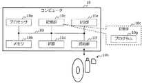
図29に示すように、情報処理装置の一例としてのコンピュータ10は、例示的に、プロセッサ10a、メモリ10b、記憶部10c、IF(Interface)部10d、I/O(Input / Output)部10e、及び読取部10fをそなえてよい。 As shown in FIG. 29, the
プロセッサ10aは、種々の制御や演算を行なう演算処理装置の一例である。プロセッサ10aは、各ブロック10b〜10fとバス10iで相互に通信可能に接続されてよい。プロセッサ10aとしては、CPU、GPU、MPU、DSP、ASIC、PLD(例えばFPGA)等の集積回路(IC)が用いられてもよい。なお、CPUはCentral Processing Unitの略称であり、GPUはGraphics Processing Unitの略称であり、MPUはMicro Processing Unitの略称である。DSPはDigital Signal Processorの略称であり、ASICはApplication Specific Integrated Circuitの略称である。PLDはProgrammable Logic Deviceの略称であり、FPGAはField Programmable Gate Arrayの略称である。 The
メモリ10bは、種々のデータやプログラムを格納するハードウェアの一例である。メモリ10bとしては、揮発性メモリ、例えば、DRAM(Dynamic RAM)等のRAMが挙げられる。なお、RAMはRandom Access Memoryの略称である。 The
記憶部10cは、種々のデータやプログラム等を格納するハードウェアの一例である。例えば、記憶部10cは、コンピュータ10の二次記憶装置として使用されてよく、OS(Operating System)やファームウェア、アプリケーション等のプログラム、及び各種データが格納されてよい。記憶部10cとしては、例えば、HDD(Hard Disk Drive)等の磁気ディスク装置、SSD(Solid State Drive)等の半導体ドライブ装置、不揮発性メモリ等の各種記憶装置が挙げられる。不揮発性メモリとしては、例えば、フラッシュメモリ、SCM(Storage Class Memory)、ROM(Read Only Memory)等が挙げられる。記憶部10cは、コンピュータ10の各種機能の全部若しくは一部を実現するプログラム10gを格納してもよい。 The
IF部10dは、図示しないネットワークを介して、他の装置との間の接続及び通信の制御等を行なう通信インタフェースの一例である。例えばIF部10dとしては、イーサネット(登録商標)、光通信(例えばFibre Channel)等に準拠したアダプタが挙げられる。なお、コンピュータ10は、管理者の管理端末との間の接続及び通信の制御等を行なう通信インタフェースをそなえてもよく、当該通信インタフェースを用いて、図示しないネットワークからプログラム10gをダウンロードしてもよい。 The
I/O部10eは、例えば、マウス、キーボード、タッチパネル、操作ボタン等の入力装置、並びに、ディスプレイや、プロジェクタ、プリンタ等の出力装置の少なくとも一方を含んでよい。 The I /
読取部10fは、記録媒体10hに記録されたデータやプログラムを読み出しプロセッサ10aに出力するリーダの一例である。読取部10fは、記録媒体10hを接続又は挿入可能な接続端子又は装置を含んでもよい。読取部10fとしては、例えばUSB(Universal Serial Bus)等に準拠したアダプタ、記録ディスクへのアクセスを行なうドライブ装置、SDカード等のフラッシュメモリへのアクセスを行なうカードリーダ等が挙げられる。なお、記録媒体10hにはプログラム10g等が格納されてもよい。 The
記録媒体10hとしては、例示的に、磁気/光ディスクやフラッシュメモリ等の非一時的なコンピュータ読取可能な記録媒体が挙げられる。磁気/光ディスクとしては、例示的に、フレキシブルディスク、CD(Compact Disc)、DVD(Digital Versatile Disc)、ブルーレイディスク、HVD(Holographic Versatile Disc)等が挙げられる。フラッシュメモリとしては、例示的に、USBメモリやSDカード等の半導体メモリが挙げられる。なお、CDとしては、例示的に、CD−ROM、CD−R、CD−RW等が挙げられる。また、DVDとしては、例示的に、DVD−ROM、DVD−RAM、DVD−R、DVD−RW、DVD+R、DVD+RW等が挙げられる。 Examples of the
上述したコンピュータ10のハードウェア構成は例示である。従って、コンピュータ10内でのハードウェアの増減(例えば任意のブロックの追加や削除)、分割、任意の組み合わせでの統合、バスの追加又は省略等は適宜行なわれてもよい。また、検出装置1が複数のコンピュータ10により実現される場合には、複数のコンピュータ10間で、1つ以上のハードウェアが共用されてもよい。 The hardware configuration of the
〔2〕その他
上述した一実施形態に係る技術は、以下のように変形、変更して実施することができる。[2] Others The technique according to the above-described embodiment can be modified or modified as follows.
例えば、図1に示す検出装置1において、画像前処理部12〜推定結果選択部16の機能は、任意の組み合わせで併合してもよく、いずれかの機能を複数の機能に分割してもよい。 For example, in the
また、スコア補正部161は、検出された物体の姿勢を検出できる場合、予測領域の推定処理に姿勢情報を用いてもよい。例えば、立ち止まった姿勢の動物が、前回の位置から急に大きく動く可能性は低いが、走ったり飛んだりしている動物は、前回の位置から大きく動くことが予想される。 Further, the
さらに、スコア補正部161は、予測領域の推定処理に、乗り物や動物等の物体の向きから予想される移動方向の情報を用いてもよい。 Further, the
なお、姿勢情報や移動方向の情報は、物体検出ネットワーク(例えばFaster R−CNN)とは別の手法によって推定されてよい。換言すれば、スコア補正部161は、物体検出ネットワークとは異なるネットワークを含んでもよい。 The attitude information and the moving direction information may be estimated by a method different from that of the object detection network (for example, Faster R-CNN). In other words, the
また、物体検出の認識処理、例えば、検出装置1による認識結果171は、物体検出用学習データのラベル付けに利用されてもよい。例えば、物体の種類をFaster R−CNNに学習させる場合、フレームごとに、物体の種類を示すラベルを人手により入力して学習させることになるが、認識結果171を利用できれば、フレームごとの入力の手間を削減できる可能性がある。 Further, the recognition process of object detection, for example, the
〔3〕付記
以上の実施形態に関し、さらに以下の付記を開示する。[3] Additional notes The following additional notes will be further disclosed with respect to the above embodiments.
(付記1)
コンピュータに、
画像系列内の第1画像について、前記第1画像内において物体の存在が推定される候補領域及び当該候補領域における前記物体の存在の可能性を示す指標の組を、前記第1画像の画像特徴量に従い複数推定し、
前記画像系列から前記物体の移動に関する移動情報を取得し、
推定した前記複数の組における前記候補領域及び前記指標を用いて前記第1画像における前記物体の位置を決定する場合に、取得した前記移動情報に基づき、推定した前記複数の組における前記候補領域及び前記指標に対する補正処理を施す、
処理を実行させる、制御プログラム。(Appendix 1)
On the computer
For the first image in the image series, the image feature of the first image is a set of a candidate region in which the existence of the object is estimated in the first image and an index indicating the possibility of the existence of the object in the candidate region. Estimate multiple according to the quantity,
Obtaining movement information regarding the movement of the object from the image series,
When the position of the object in the first image is determined using the candidate area and the index in the estimated plurality of sets, the candidate area and the candidate area in the plurality of sets estimated based on the acquired movement information. Correcting the index
A control program that executes processing.
(付記2)
前記コンピュータに、
前記画像系列内の前記第1画像よりも時間的に過去の複数の画像の各々について、当該画像ごとに、
前記画像内において物体の存在が推定される候補領域及び当該候補領域における前記物体の存在の可能性を示す指標の組を、前記画像の画像特徴量に従い複数推定し、
前記画像系列から前記物体の移動に関する移動情報を取得し、
推定した前記複数の組における前記候補領域及び前記指標を用いて前記画像における前記物体の位置を決定する場合に、取得した前記移動情報に基づき、推定した前記複数の組における前記候補領域及び前記指標に対する補正処理を施す、
処理を実行させ、
前記第1画像に係る前記移動情報の取得は、
前記過去の複数の画像の各々について当該画像ごとに決定した物体の位置に基づき同一物体と認識される物体の位置の時間的な変化に基づいて、前記移動情報を取得する、付記1に記載の制御プログラム。(Appendix 2)
To the computer
For each of the plurality of images in the past in time from the first image in the image series, for each image,
A plurality of sets of candidate regions in which the presence of an object is estimated in the image and indicators indicating the possibility of the existence of the object in the candidate region are estimated according to the image feature amount of the image.
Obtaining movement information regarding the movement of the object from the image series,
When the position of the object in the image is determined using the candidate area and the index in the estimated plurality of sets, the candidate area and the index in the estimated plurality of sets are based on the acquired movement information. Is corrected for
Execute the process,
The acquisition of the movement information related to the first image is
The description in
(付記3)
前記決定は、前記複数の組の各々の指標に基づき前記複数の組を所定数の組に絞り込む処理を含み、
前記移動情報は、前記絞り込む処理の処理対象である複数の候補領域のうちの特定の候補領域の指標を補正する補正情報を含む、付記1に記載の制御プログラム。(Appendix 3)
The determination includes the process of narrowing down the plurality of sets to a predetermined number of sets based on the index of each of the plurality of sets.
The control program according to
(付記4)
前記決定は、前記複数の組の各々の指標に基づき前記複数の組の複数の候補領域の重み付き平均を算出する処理を含み、
前記移動情報は、前記重み付き平均を算出する処理の処理対象である複数の候補領域の各々の重み情報を含む、付記1に記載の制御プログラム。(Appendix 4)
The determination comprises the process of calculating the weighted average of the plurality of candidate regions of the plurality of sets based on the respective indicators of the plurality of sets.
The control program according to
(付記5)
前記第1画像には複数の基準領域が固定的に配置されており、
前記推定は、前記複数の基準領域の各々により形成される領域、又は、前記複数の基準領域の組み合わせにより形成される領域に基づき、前記候補領域及び前記指標の複数の組を推定する、付記1〜4のいずれか1項に記載の制御プログラム。(Appendix 5)
A plurality of reference regions are fixedly arranged in the first image.
The estimation estimates a plurality of sets of the candidate region and the index based on a region formed by each of the plurality of reference regions or a region formed by a combination of the plurality of reference regions. The control program according to any one of 4 to 4.
(付記6)
前記移動情報の取得は、前記物体の位置情報と、前記画像系列内の前記第1画像及び前記第1画像の直前の画像の時間間隔と、に基づき、前記第1画像において当該物体が存在し得る領域を推定する、付記1〜5のいずれか1項に記載の制御プログラム。(Appendix 6)
The acquisition of the movement information is based on the position information of the object and the time interval between the first image in the image series and the image immediately before the first image, and the object exists in the first image. The control program according to any one of
(付記7)
前記移動情報の取得は、追尾フィルタを用いた運動モデルに基づき、前記移動情報を取得する、付記1〜6のいずれか1項に記載の制御プログラム。(Appendix 7)
The control program according to any one of
(付記8)
前記移動情報の取得は、前記追尾フィルタにより推定された複数の追尾対象の領域と、前記物体の位置情報との対応付けを行なう、付記7に記載の制御プログラム。(Appendix 8)
The control program according to Appendix 7, wherein the movement information is acquired by associating a plurality of tracking target areas estimated by the tracking filter with the position information of the object.
(付記9)
前記移動情報の取得は、前記対応付けにより得られた複数の追尾仮説の各々の尤度に基づき、1以上の追尾仮説を前記移動情報として取得する、付記8に記載の制御プログラム。(Appendix 9)
The control program according to Appendix 8, wherein the movement information is acquired based on the likelihood of each of the plurality of tracking hypotheses obtained by the correspondence, and one or more tracking hypotheses are acquired as the movement information.
(付記10)
前記移動情報は、
前記複数の候補領域の各々と、前記追尾フィルタにより得られる、前記第1画像において前記物体が存在し得る領域との距離、マハラノビス距離、前記複数の候補領域の各々の指標、及び、前記複数の追尾対象の各々の尤度、のいずれか1つ又は2つ以上の組み合わせの情報を含む、付記9に記載の制御プログラム。(Appendix 10)
The movement information is
The distance between each of the plurality of candidate regions and the region where the object can exist in the first image obtained by the tracking filter, the Mahalanobis distance, each index of the plurality of candidate regions, and the plurality of candidates. The control program according to
(付記11)
前記移動情報の取得は、前記追尾フィルタにより得られる、前記第1画像において前記物体が存在し得る領域を中心とするゲート領域内部に存在する候補領域の指標に対して、前記移動情報に基づく重み付けを行なう、付記7〜10のいずれか1項に記載の制御プログラム。(Appendix 11)
The acquisition of the movement information is weighted based on the movement information with respect to the index of the candidate region existing inside the gate region centered on the region where the object can exist in the first image, which is obtained by the tracking filter. The control program according to any one of Supplementary note 7 to 10.
(付記12)
画像系列内の第1画像について、前記第1画像内において物体の存在が推定される候補領域及び当該候補領域における前記物体の存在の可能性を示す指標の組を、前記第1画像の画像特徴量に従い複数推定し、
前記画像系列から前記物体の移動に関する移動情報を取得し、
推定した前記複数の組における前記候補領域及び前記指標を用いて前記第1画像における前記物体の位置を決定する場合に、取得した前記移動情報に基づき、推定した前記複数の組における前記候補領域及び前記指標に対する補正処理を施す、制御方法。(Appendix 12)
For the first image in the image series, the image feature of the first image is a set of a candidate region in which the existence of the object is estimated in the first image and an index indicating the possibility of the existence of the object in the candidate region. Estimate multiple according to the quantity,
Obtaining movement information regarding the movement of the object from the image series,
When the position of the object in the first image is determined using the candidate area and the index in the estimated plurality of sets, the candidate area and the candidate area in the plurality of sets estimated based on the acquired movement information. A control method for performing correction processing on the index.
(付記13)
前記画像系列内の前記第1画像よりも時間的に過去の複数の画像の各々について、当該画像ごとに、
前記画像内において物体の存在が推定される候補領域及び当該候補領域における前記物体の存在の可能性を示す指標の組を、前記画像の画像特徴量に従い複数推定し、
前記画像系列から前記物体の移動に関する移動情報を取得し、
推定した前記複数の組における前記候補領域及び前記指標を用いて前記画像における前記物体の位置を決定する場合に、取得した前記移動情報に基づき、推定した前記複数の組における前記候補領域及び前記指標に対する補正処理を施し、
前記第1画像に係る前記移動情報の取得は、
前記過去の複数の画像の各々について当該画像ごとに決定した物体の位置に基づき同一物体と認識される物体の位置の時間的な変化に基づいて、前記移動情報を取得する、付記12に記載の制御方法。(Appendix 13)
For each of the plurality of images in the past in time from the first image in the image series, for each image,
A plurality of sets of candidate regions in which the presence of an object is estimated in the image and indicators indicating the possibility of the existence of the object in the candidate region are estimated according to the image feature amount of the image.
Obtaining movement information regarding the movement of the object from the image series,
When the position of the object in the image is determined using the candidate area and the index in the estimated plurality of sets, the candidate area and the index in the estimated plurality of sets are based on the acquired movement information. Is corrected for
The acquisition of the movement information related to the first image is
The moving information is acquired based on the temporal change of the position of the object recognized as the same object based on the position of the object determined for each of the plurality of past images, according to
(付記14)
前記決定は、前記複数の組の各々の指標に基づき前記複数の組を所定数の組に絞り込む処理を含み、
前記移動情報は、前記第1画像に係る前記絞り込む処理の処理対象である複数の候補領域のうちの特定の候補領域の指標を補正する補正情報を含む、付記12に記載の制御方法。(Appendix 14)
The determination includes the process of narrowing down the plurality of sets to a predetermined number of sets based on the index of each of the plurality of sets.
The control method according to
(付記15)
前記決定は、前記複数の組の各々の指標に基づき前記複数の組の複数の候補領域の重み付き平均を算出する処理を含み、
前記移動情報は、前記次に入力される入力画像に係る前記重み付き平均を算出する処理の処理対象である複数の候補領域の各々の重み情報を含む、付記12に記載の制御方法。(Appendix 15)
The determination comprises the process of calculating the weighted average of the plurality of candidate regions of the plurality of sets based on the respective indicators of the plurality of sets.
The control method according to
(付記16)
前記入力画像には複数の基準領域が固定的に配置されており、
前記推定は、前記複数の基準領域の各々により形成される領域、又は、前記複数の基準領域の組み合わせにより形成される領域に基づき、前記候補領域及び前記指標の複数の組を推定する、付記12〜15のいずれか1項に記載の制御方法。(Appendix 16)
A plurality of reference regions are fixedly arranged in the input image, and the input image has a plurality of reference regions fixedly arranged.
The estimation estimates a plurality of sets of the candidate region and the index based on a region formed by each of the plurality of reference regions or a region formed by a combination of the plurality of reference regions. The control method according to any one of 15 to 15.
(付記17)
画像系列内の第1画像について、前記第1画像内において物体の存在が推定される候補領域及び当該候補領域における前記物体の存在の可能性を示す指標の組を、前記第1画像の画像特徴量に従い複数推定する推定部と、
前記画像系列から前記物体の移動に関する移動情報を取得する取得部と、
推定した前記複数の組における前記候補領域及び前記指標を用いて前記第1画像における前記物体の位置を決定する場合に、取得した前記移動情報に基づき、推定した前記複数の組における前記候補領域及び前記指標に対する補正処理を施す処理部と、をそなえる、情報処理装置。(Appendix 17)
For the first image in the image series, the image feature of the first image is a set of a candidate region in which the existence of the object is estimated in the first image and an index indicating the possibility of the existence of the object in the candidate region. An estimation unit that estimates multiple images according to the quantity, and an estimation unit
An acquisition unit that acquires movement information regarding the movement of the object from the image series, and
When the position of the object in the first image is determined using the candidate area and the index in the estimated plurality of sets, the candidate area and the candidate area in the plurality of sets estimated based on the acquired movement information. An information processing device including a processing unit that performs correction processing on the index.
(付記18)
前記推定部は、前記画像系列内の前記第1画像よりも時間的に過去の複数の画像の各々について、当該画像ごとに、前記画像内において物体の存在が推定される候補領域及び当該候補領域における前記物体の存在の可能性を示す指標の組を、前記画像の画像特徴量に従い複数推定し、
前記取得部は、前記画像系列内の前記第1画像よりも時間的に過去の複数の画像の各々について、当該画像ごとに、前記画像系列から前記物体の移動に関する移動情報を取得し、
前記処理部は、前記画像系列内の前記第1画像よりも時間的に過去の複数の画像の各々について、当該画像ごとに、推定した前記複数の組における前記候補領域及び前記指標を用いて前記画像における前記物体の位置を決定する場合に、取得した前記移動情報に基づき、推定した前記複数の組における前記候補領域及び前記指標に対する補正処理を施し、
前記取得部は、前記第1画像に係る処理において、前記過去の複数の画像の各々について当該画像ごとに決定した物体の位置に基づき同一物体と認識される物体の位置の時間的な変化に基づいて、前記移動情報を取得する、付記17に記載の情報処理装置。(Appendix 18)
The estimation unit has a candidate region and a candidate region in which the presence of an object in the image is estimated for each of the plurality of images in the image series in time past the first image. A plurality of sets of indicators indicating the possibility of the existence of the object in the above are estimated according to the image feature amount of the image.
The acquisition unit acquires movement information regarding the movement of the object from the image series for each of the plurality of images in the past in terms of time from the first image in the image series.
The processing unit uses the candidate region and the index in the plurality of sets estimated for each of the plurality of images in the past of the first image in the image series for each image. When determining the position of the object in the image, correction processing is performed on the candidate region and the index in the estimated plurality of sets based on the acquired movement information.
The acquisition unit is based on a temporal change in the position of an object recognized as the same object based on the position of the object determined for each of the plurality of past images in the process relating to the first image. The information processing device according to
(付記19)
前記決定部は、前記複数の組の各々の指標に基づき前記複数の組を所定数の組に絞り込む処理を実行し、
前記移動情報は、前記第1画像に係る前記絞り込む処理の処理対象である複数の候補領域のうちの特定の候補領域の指標を補正する補正情報を含む、付記17に記載の情報処理装置。(Appendix 19)
The determination unit executes a process of narrowing down the plurality of sets to a predetermined number of sets based on the index of each of the plurality of sets.
The information processing apparatus according to
(付記20)
前記決定部は、前記複数の組の各々の指標に基づき前記複数の組の複数の候補領域の重み付き平均を算出する処理を実行し、
前記移動情報は、前記第1画像に係る前記重み付き平均を算出する処理の処理対象である複数の候補領域の各々の重み情報を含む、付記17に記載の情報処理装置。(Appendix 20)
The determination unit executes a process of calculating a weighted average of a plurality of candidate regions of the plurality of sets based on each index of the plurality of sets.
The information processing apparatus according to
1 検出装置
10 コンピュータ
11、17 メモリ部
111 画像データ
12 画像前処理部
13 特徴マップ計算部
130 CNN層
14 提案領域計算部
140 RPN層
141 候補領域・スコア計算部
142 候補領域選択部
143 アンカー群
144 入力画像
15 物体位置・種類推定部
150 Fast R−CNN層
16 推定結果選択部
161 スコア補正部
162 取得部
171 認識結果1
Claims (9)
Translated fromJapanese画像系列内の第1画像について、前記第1画像内において物体の存在が推定される候補領域及び当該候補領域における前記物体の存在の可能性を示す指標の組を、前記第1画像の画像特徴量に従い複数推定し、
前記画像系列内の前記第1画像よりも時間的に過去の複数の画像から前記物体の移動に関する移動情報を取得し、
推定した前記複数の組における前記候補領域及び前記指標を用いて前記第1画像における前記物体の位置を決定する場合に、取得した前記移動情報に基づき、推定した前記複数の組における前記候補領域及び前記指標に対する補正処理を施す、
処理を実行させる、制御プログラム。On the computer
For the first image in the image series, the image feature of the first image is a set of a candidate region in which the existence of the object is estimated in the first image and an index indicating the possibility of the existence of the object in the candidate region. Estimate multiple according to the quantity,
Movement information regarding the movement of the object is acquired froma plurality of images in the past in time from the first image in the image series.
When the position of the object in the first image is determined using the candidate area and the index in the estimated plurality of sets, the candidate area and the candidate area in the plurality of sets estimated based on the acquired movement information. Correcting the index
A control program that executes processing.
前記画像系列内の前記第1画像よりも時間的に過去の前記複数の画像の各々について、当該画像ごとに、
前記画像内において物体の存在が推定される候補領域及び当該候補領域における前記物体の存在の可能性を示す指標の組を、前記画像の画像特徴量に従い複数推定し、
前記画像系列から前記物体の移動に関する移動情報を取得し、
推定した前記複数の組における前記候補領域及び前記指標を用いて前記画像における前記物体の位置を決定する場合に、取得した前記移動情報に基づき、推定した前記複数の組における前記候補領域及び前記指標に対する補正処理を施す、
処理を実行させ、
前記第1画像に係る前記移動情報の取得は、
前記過去の複数の画像の各々について当該画像ごとに決定した物体の位置に基づき同一物体と認識される物体の位置の時間的な変化に基づいて、前記移動情報を取得する、請求項1に記載の制御プログラム。To the computer
For each of the first image also temporally than pastsaid plurality of images of the image sequence, each said image,
A plurality of sets of candidate regions in which the presence of an object is estimated in the image and indicators indicating the possibility of the existence of the object in the candidate region are estimated according to the image feature amount of the image.
Obtaining movement information regarding the movement of the object from the image series,
When the position of the object in the image is determined using the candidate area and the index in the estimated plurality of sets, the candidate area and the index in the estimated plurality of sets are based on the acquired movement information. Is corrected for
Execute the process,
The acquisition of the movement information related to the first image is
The first aspect of claim 1, wherein the movement information is acquired based on the temporal change of the position of the object recognized as the same object based on the position of the object determined for each of the plurality of past images. Control program.
前記移動情報は、前記絞り込む処理の処理対象である複数の候補領域のうちの特定の候補領域の指標を補正する補正情報を含む、請求項1に記載の制御プログラム。The determination includes the process of narrowing down the plurality of sets to a predetermined number of sets based on the index of each of the plurality of sets.
The control program according to claim 1, wherein the movement information includes correction information for correcting an index of a specific candidate area among a plurality of candidate areas to be processed for the narrowing process.
前記移動情報は、前記重み付き平均を算出する処理の処理対象である複数の候補領域の各々の重み情報を含む、請求項1に記載の制御プログラム。The determination comprises the process of calculating the weighted average of the plurality of candidate regions of the plurality of sets based on the respective indicators of the plurality of sets.
The control program according to claim 1, wherein the movement information includes weight information of each of a plurality of candidate regions to be processed in the process of calculating the weighted average.
前記推定は、前記複数の基準領域の各々により形成される領域、又は、前記複数の基準領域の組み合わせにより形成される領域に基づき、前記候補領域及び前記指標の複数の組を推定する、請求項1〜4のいずれか1項に記載の制御プログラム。A plurality of reference regions are fixedly arranged in the first image.
The estimation estimates a plurality of sets of the candidate region and the index based on a region formed by each of the plurality of reference regions or a region formed by a combination of the plurality of reference regions. The control program according to any one of 1 to 4.
前記画像系列内の前記第1画像よりも時間的に過去の複数の画像から前記物体の移動に関する移動情報を取得し、
推定した前記複数の組における前記候補領域及び前記指標を用いて前記第1画像における前記物体の位置を決定する場合に、取得した前記移動情報に基づき、推定した前記複数の組における前記候補領域及び前記指標に対する補正処理を施す、制御方法。For the first image in the image series, the image feature of the first image is a set of a candidate region in which the existence of the object is estimated in the first image and an index indicating the possibility of the existence of the object in the candidate region. Estimate multiple according to the quantity,
Movement information regarding the movement of the object is acquired froma plurality of images in the past in time from the first image in the image series.
When the position of the object in the first image is determined using the candidate area and the index in the estimated plurality of sets, the candidate area and the candidate area in the plurality of sets estimated based on the acquired movement information. A control method for performing correction processing on the index.
前記画像系列内の前記第1画像よりも時間的に過去の複数の画像から前記物体の移動に関する移動情報を取得する取得部と、
推定した前記複数の組における前記候補領域及び前記指標を用いて前記第1画像における前記物体の位置を決定する場合に、取得した前記移動情報に基づき、推定した前記複数の組における前記候補領域及び前記指標に対する補正処理を施す処理部と、をそなえる、情報処理装置。For the first image in the image series, the image feature of the first image is a set of a candidate region in which the existence of the object is estimated in the first image and an index indicating the possibility of the existence of the object in the candidate region. An estimation unit that estimates multiple images according to the quantity, and an estimation unit
An acquisition unit that acquires movement information regarding the movement of the object froma plurality of images in the past in terms of time from the first image in the image series.
When the position of the object in the first image is determined using the candidate area and the index in the estimated plurality of sets, the candidate area and the candidate area in the plurality of sets estimated based on the acquired movement information. An information processing device including a processing unit that performs correction processing on the index.
Priority Applications (2)
| Application Number | Priority Date | Filing Date | Title |
|---|---|---|---|
| JP2017155263AJP6972757B2 (en) | 2017-08-10 | 2017-08-10 | Control programs, control methods, and information processing equipment |
| US16/054,188US10672131B2 (en) | 2017-08-10 | 2018-08-03 | Control method, non-transitory computer-readable storage medium, and control apparatus |
Applications Claiming Priority (1)
| Application Number | Priority Date | Filing Date | Title |
|---|---|---|---|
| JP2017155263AJP6972757B2 (en) | 2017-08-10 | 2017-08-10 | Control programs, control methods, and information processing equipment |
Publications (2)
| Publication Number | Publication Date |
|---|---|
| JP2019036009A JP2019036009A (en) | 2019-03-07 |
| JP6972757B2true JP6972757B2 (en) | 2021-11-24 |
Family
ID=65275279
Family Applications (1)
| Application Number | Title | Priority Date | Filing Date |
|---|---|---|---|
| JP2017155263AExpired - Fee RelatedJP6972757B2 (en) | 2017-08-10 | 2017-08-10 | Control programs, control methods, and information processing equipment |
Country Status (2)
| Country | Link |
|---|---|
| US (1) | US10672131B2 (en) |
| JP (1) | JP6972757B2 (en) |
Families Citing this family (36)
| Publication number | Priority date | Publication date | Assignee | Title |
|---|---|---|---|---|
| FR3028690B1 (en)* | 2014-11-18 | 2017-12-01 | Renault Sas | METHOD FOR CONTROLLING A SYNCHRONOUS ROTOR COIL ELECTRIC MACHINE |
| CN117915108A (en) | 2017-05-19 | 2024-04-19 | 渊慧科技有限公司 | Visual interactive network system and method thereof, training method and computer storage medium |
| JP6972757B2 (en) | 2017-08-10 | 2021-11-24 | 富士通株式会社 | Control programs, control methods, and information processing equipment |
| JP6972756B2 (en)* | 2017-08-10 | 2021-11-24 | 富士通株式会社 | Control programs, control methods, and information processing equipment |
| US10769485B2 (en)* | 2018-06-19 | 2020-09-08 | Himax Technologies Limited | Framebuffer-less system and method of convolutional neural network |
| US10878270B1 (en)* | 2018-06-26 | 2020-12-29 | Amazon Technologies, Inc. | Keypoint-based multi-label word segmentation and localization |
| US10387752B1 (en)* | 2019-01-22 | 2019-08-20 | StradVision, Inc. | Learning method and learning device for object detector with hardware optimization based on CNN for detection at distance or military purpose using image concatenation, and testing method and testing device using the same |
| US10423860B1 (en)* | 2019-01-22 | 2019-09-24 | StradVision, Inc. | Learning method and learning device for object detector based on CNN to be used for multi-camera or surround view monitoring using image concatenation and target object merging network, and testing method and testing device using the same |
| US10430691B1 (en)* | 2019-01-22 | 2019-10-01 | StradVision, Inc. | Learning method and learning device for object detector based on CNN, adaptable to customers' requirements such as key performance index, using target object merging network and target region estimating network, and testing method and testing device using the same to be used for multi-camera or surround view monitoring |
| US10402695B1 (en)* | 2019-01-23 | 2019-09-03 | StradVision, Inc. | Learning method and learning device for convolutional neural network using 1×H convolution for image recognition to be used for hardware optimization, and testing method and testing device using the same |
| US10387754B1 (en)* | 2019-01-23 | 2019-08-20 | StradVision, Inc. | Learning method and learning device for object detector based on CNN using 1×H convolution to be used for hardware optimization, and testing method and testing device using the same |
| CN111612726A (en)* | 2019-02-26 | 2020-09-01 | 广州慧睿思通信息科技有限公司 | Image data screening method and device, computer equipment and storage medium |
| WO2020174770A1 (en)* | 2019-02-28 | 2020-09-03 | 富士フイルム株式会社 | Area specifying device, method, program, learning device, method, program, and identifying device |
| CN109919981B (en)* | 2019-03-11 | 2022-08-02 | 南京邮电大学 | A multi-target tracking method based on Kalman filter-assisted multi-feature fusion |
| US11277556B2 (en)* | 2019-04-01 | 2022-03-15 | Jvckenwood Corporation | Control device for automatic tracking camera |
| CN109978886B (en)* | 2019-04-01 | 2021-11-09 | 北京市商汤科技开发有限公司 | Image processing method and device, electronic equipment and storage medium |
| JP2020177409A (en)* | 2019-04-17 | 2020-10-29 | 淳 宮▲崎▼ | Information processing device, information processing method, and information processing program |
| CN112307826A (en) | 2019-07-30 | 2021-02-02 | 华为技术有限公司 | Pedestrian detection method, device, computer-readable storage medium and chip |
| JP7078021B2 (en)* | 2019-08-08 | 2022-05-31 | トヨタ自動車株式会社 | Object detection device, object detection method and computer program for object detection |
| US11043003B2 (en)* | 2019-11-18 | 2021-06-22 | Waymo Llc | Interacted object detection neural network |
| JP7490359B2 (en)* | 2019-12-24 | 2024-05-27 | キヤノン株式会社 | Information processing device, information processing method, and program |
| WO2021171498A1 (en)* | 2020-02-27 | 2021-09-02 | 三菱電機株式会社 | Target tracking device, target tracking system, and target tracking method |
| US12406380B2 (en) | 2020-03-12 | 2025-09-02 | Nec Corporation | Image processing apparatus, image processing system, image processing method, and non-transitory computer-readable medium storing image processing program therein |
| CN111524165B (en)* | 2020-04-22 | 2023-08-25 | 北京百度网讯科技有限公司 | Target tracking method and device |
| JP6859472B1 (en)* | 2020-06-16 | 2021-04-14 | エヌ・ティ・ティ・コミュニケーションズ株式会社 | Object tracking device, object tracking method and program |
| JP7435298B2 (en)* | 2020-06-22 | 2024-02-21 | オムロン株式会社 | Object detection device and object detection method |
| US11544509B2 (en)* | 2020-06-30 | 2023-01-03 | Nielsen Consumer Llc | Methods, systems, articles of manufacture, and apparatus to classify labels based on images using artificial intelligence |
| CN112132162B (en)* | 2020-09-08 | 2024-04-02 | Oppo广东移动通信有限公司 | Image processing method, image processor, electronic device, and readable storage medium |
| US12045992B2 (en)* | 2020-11-10 | 2024-07-23 | Nec Corporation | Multi-domain semantic segmentation with label shifts |
| CN112378458B (en)* | 2020-12-04 | 2022-06-03 | 四川长虹电器股份有限公司 | Operation monitoring method for unattended sand production ship |
| CN116685904A (en)* | 2020-12-28 | 2023-09-01 | 富士胶片株式会社 | Camera support device, camera device, camera support method and program |
| CN114764773A (en)* | 2021-01-12 | 2022-07-19 | 欧姆龙(上海)有限公司 | Article detection method and device and electronic equipment |
| JP7698481B2 (en)* | 2021-06-15 | 2025-06-25 | Astemo株式会社 | Detection frame position accuracy improvement system and detection frame position correction method |
| JP7721425B2 (en)* | 2021-12-17 | 2025-08-13 | 株式会社東芝 | Radar system and radar signal processing method |
| JPWO2024013893A1 (en)* | 2022-07-13 | 2024-01-18 | ||
| JP2024098747A (en)* | 2023-01-11 | 2024-07-24 | トヨタ自動車株式会社 | Moving object search device |
Family Cites Families (16)
| Publication number | Priority date | Publication date | Assignee | Title |
|---|---|---|---|---|
| US5708473A (en)* | 1994-08-30 | 1998-01-13 | Hughes Aircraft Company | Two stage video film compression method and system |
| JP3560670B2 (en) | 1995-02-06 | 2004-09-02 | 富士通株式会社 | Adaptive recognition system |
| US6674925B1 (en)* | 2000-02-08 | 2004-01-06 | University Of Washington | Morphological postprocessing for object tracking and segmentation |
| GB2431787B (en)* | 2005-10-31 | 2009-07-01 | Hewlett Packard Development Co | A method of tracking an object in a video stream |
| JP4725490B2 (en) | 2006-10-27 | 2011-07-13 | パナソニック電工株式会社 | Automatic tracking method |
| TWI348659B (en)* | 2007-10-29 | 2011-09-11 | Ind Tech Res Inst | Method and system for object detection and tracking |
| JP5675229B2 (en)* | 2010-09-02 | 2015-02-25 | キヤノン株式会社 | Image processing apparatus and image processing method |
| JP5823270B2 (en)* | 2011-11-30 | 2015-11-25 | Kddi株式会社 | Image recognition apparatus and method |
| CN104517275A (en)* | 2013-09-27 | 2015-04-15 | 株式会社理光 | Object detection method and system |
| JP6282193B2 (en)* | 2014-07-28 | 2018-02-21 | クラリオン株式会社 | Object detection device |
| US9594947B1 (en)* | 2014-09-30 | 2017-03-14 | Amazon Technologies, Inc. | Aspect ratio validation |
| WO2016054778A1 (en) | 2014-10-09 | 2016-04-14 | Microsoft Technology Licensing, Llc | Generic object detection in images |
| JP6447108B2 (en) | 2014-12-24 | 2019-01-09 | 富士通株式会社 | Usability calculation device, availability calculation method, and availability calculation program |
| JP6283008B2 (en)* | 2015-10-13 | 2018-02-21 | セコム株式会社 | Tracking device |
| US11205283B2 (en)* | 2017-02-16 | 2021-12-21 | Qualcomm Incorporated | Camera auto-calibration with gyroscope |
| JP6972757B2 (en) | 2017-08-10 | 2021-11-24 | 富士通株式会社 | Control programs, control methods, and information processing equipment |
- 2017
- 2017-08-10JPJP2017155263Apatent/JP6972757B2/ennot_activeExpired - Fee Related
- 2018
- 2018-08-03USUS16/054,188patent/US10672131B2/ennot_activeExpired - Fee Related
Also Published As
| Publication number | Publication date |
|---|---|
| US10672131B2 (en) | 2020-06-02 |
| US20190050994A1 (en) | 2019-02-14 |
| JP2019036009A (en) | 2019-03-07 |
Similar Documents
| Publication | Publication Date | Title |
|---|---|---|
| JP6972757B2 (en) | Control programs, control methods, and information processing equipment | |
| JP6972756B2 (en) | Control programs, control methods, and information processing equipment | |
| EP3620979B1 (en) | Learning method, learning device for detecting object using edge image and testing method, testing device using the same | |
| JP6759411B2 (en) | Object tracking method and equipment | |
| EP3620956B1 (en) | Learning method, learning device for detecting lane through classification of lane candidate pixels and testing method, testing device using the same | |
| CN109426782B (en) | Object detection method and neural network system for object detection | |
| US9626766B2 (en) | Depth sensing using an RGB camera | |
| JP6204659B2 (en) | Video processing apparatus and video processing method | |
| KR102279376B1 (en) | Learning method, learning device for detecting lane using cnn and test method, test device using the same | |
| KR102279388B1 (en) | Learning method, learning device for detecting lane using lane model and test method, test device using the same | |
| US9672634B2 (en) | System and a method for tracking objects | |
| US11544926B2 (en) | Image processing apparatus, method of processing image, and storage medium | |
| CN105938622A (en) | Method and apparatus for detecting object in moving image | |
| US9443137B2 (en) | Apparatus and method for detecting body parts | |
| KR20130121202A (en) | Method and apparatus for tracking object in image data, and storage medium storing the same | |
| WO2016179808A1 (en) | An apparatus and a method for face parts and face detection | |
| KR102655789B1 (en) | Face detecting method and apparatus | |
| KR20210099450A (en) | Far away small drone detection method Using Deep Learning | |
| EP3376470B1 (en) | Moving body tracking method, moving body tracking device, and program | |
| CN117593548A (en) | Visual SLAM method for removing dynamic feature points based on weighted attention mechanism | |
| CN116524377A (en) | Unmanned aerial vehicle target tracking and identifying method based on TIR image | |
| JP6713422B2 (en) | Learning device, event detection device, learning method, event detection method, program | |
| KR102336284B1 (en) | Moving Object Detection Method and System with Single Camera | |
| KR101506812B1 (en) | Head pose estimation method using random forests and binary pattern run length matrix | |
| JP7240940B2 (en) | Object image extraction device, method, and software program |
Legal Events
| Date | Code | Title | Description |
|---|---|---|---|
| RD04 | Notification of resignation of power of attorney | Free format text:JAPANESE INTERMEDIATE CODE: A7424 Effective date:20190607 | |
| A621 | Written request for application examination | Free format text:JAPANESE INTERMEDIATE CODE: A621 Effective date:20200514 | |
| A977 | Report on retrieval | Free format text:JAPANESE INTERMEDIATE CODE: A971007 Effective date:20210628 | |
| A131 | Notification of reasons for refusal | Free format text:JAPANESE INTERMEDIATE CODE: A131 Effective date:20210713 | |
| A521 | Request for written amendment filed | Free format text:JAPANESE INTERMEDIATE CODE: A523 Effective date:20210910 | |
| TRDD | Decision of grant or rejection written | ||
| A01 | Written decision to grant a patent or to grant a registration (utility model) | Free format text:JAPANESE INTERMEDIATE CODE: A01 Effective date:20211005 | |
| A61 | First payment of annual fees (during grant procedure) | Free format text:JAPANESE INTERMEDIATE CODE: A61 Effective date:20211018 | |
| R150 | Certificate of patent or registration of utility model | Ref document number:6972757 Country of ref document:JP Free format text:JAPANESE INTERMEDIATE CODE: R150 | |
| LAPS | Cancellation because of no payment of annual fees |