JP6972328B2 - Coated components with adaptive cooling openings and methods of their manufacture - Google Patents
Coated components with adaptive cooling openings and methods of their manufactureDownload PDFInfo
- Publication number
- JP6972328B2 JP6972328B2JP2020519999AJP2020519999AJP6972328B2JP 6972328 B2JP6972328 B2JP 6972328B2JP 2020519999 AJP2020519999 AJP 2020519999AJP 2020519999 AJP2020519999 AJP 2020519999AJP 6972328 B2JP6972328 B2JP 6972328B2
- Authority
- JP
- Japan
- Prior art keywords
- wall
- component
- adaptive cooling
- coating system
- adaptive
- Prior art date
- Legal status (The legal status is an assumption and is not a legal conclusion. Google has not performed a legal analysis and makes no representation as to the accuracy of the status listed.)
- Active
Links
Images


Classifications
- F—MECHANICAL ENGINEERING; LIGHTING; HEATING; WEAPONS; BLASTING
- F01—MACHINES OR ENGINES IN GENERAL; ENGINE PLANTS IN GENERAL; STEAM ENGINES
- F01D—NON-POSITIVE DISPLACEMENT MACHINES OR ENGINES, e.g. STEAM TURBINES
- F01D5/00—Blades; Blade-carrying members; Heating, heat-insulating, cooling or antivibration means on the blades or the members
- F01D5/12—Blades
- F01D5/14—Form or construction
- F01D5/18—Hollow blades, i.e. blades with cooling or heating channels or cavities; Heating, heat-insulating or cooling means on blades
- F01D5/182—Transpiration cooling
- F—MECHANICAL ENGINEERING; LIGHTING; HEATING; WEAPONS; BLASTING
- F01—MACHINES OR ENGINES IN GENERAL; ENGINE PLANTS IN GENERAL; STEAM ENGINES
- F01D—NON-POSITIVE DISPLACEMENT MACHINES OR ENGINES, e.g. STEAM TURBINES
- F01D5/00—Blades; Blade-carrying members; Heating, heat-insulating, cooling or antivibration means on the blades or the members
- F01D5/12—Blades
- F01D5/28—Selecting particular materials; Particular measures relating thereto; Measures against erosion or corrosion
- F01D5/288—Protective coatings for blades
- F—MECHANICAL ENGINEERING; LIGHTING; HEATING; WEAPONS; BLASTING
- F01—MACHINES OR ENGINES IN GENERAL; ENGINE PLANTS IN GENERAL; STEAM ENGINES
- F01D—NON-POSITIVE DISPLACEMENT MACHINES OR ENGINES, e.g. STEAM TURBINES
- F01D25/00—Component parts, details, or accessories, not provided for in, or of interest apart from, other groups
- F01D25/08—Cooling; Heating; Heat-insulation
- F01D25/12—Cooling
- F—MECHANICAL ENGINEERING; LIGHTING; HEATING; WEAPONS; BLASTING
- F01—MACHINES OR ENGINES IN GENERAL; ENGINE PLANTS IN GENERAL; STEAM ENGINES
- F01D—NON-POSITIVE DISPLACEMENT MACHINES OR ENGINES, e.g. STEAM TURBINES
- F01D5/00—Blades; Blade-carrying members; Heating, heat-insulating, cooling or antivibration means on the blades or the members
- F01D5/12—Blades
- F01D5/14—Form or construction
- F01D5/18—Hollow blades, i.e. blades with cooling or heating channels or cavities; Heating, heat-insulating or cooling means on blades
- F01D5/186—Film cooling
- F—MECHANICAL ENGINEERING; LIGHTING; HEATING; WEAPONS; BLASTING
- F01—MACHINES OR ENGINES IN GENERAL; ENGINE PLANTS IN GENERAL; STEAM ENGINES
- F01D—NON-POSITIVE DISPLACEMENT MACHINES OR ENGINES, e.g. STEAM TURBINES
- F01D5/00—Blades; Blade-carrying members; Heating, heat-insulating, cooling or antivibration means on the blades or the members
- F01D5/12—Blades
- F01D5/14—Form or construction
- F01D5/18—Hollow blades, i.e. blades with cooling or heating channels or cavities; Heating, heat-insulating or cooling means on blades
- F01D5/187—Convection cooling
- F01D5/188—Convection cooling with an insert in the blade cavity to guide the cooling fluid, e.g. forming a separation wall
- F—MECHANICAL ENGINEERING; LIGHTING; HEATING; WEAPONS; BLASTING
- F01—MACHINES OR ENGINES IN GENERAL; ENGINE PLANTS IN GENERAL; STEAM ENGINES
- F01D—NON-POSITIVE DISPLACEMENT MACHINES OR ENGINES, e.g. STEAM TURBINES
- F01D5/00—Blades; Blade-carrying members; Heating, heat-insulating, cooling or antivibration means on the blades or the members
- F01D5/12—Blades
- F01D5/28—Selecting particular materials; Particular measures relating thereto; Measures against erosion or corrosion
- F01D5/284—Selection of ceramic materials
- F—MECHANICAL ENGINEERING; LIGHTING; HEATING; WEAPONS; BLASTING
- F05—INDEXING SCHEMES RELATING TO ENGINES OR PUMPS IN VARIOUS SUBCLASSES OF CLASSES F01-F04
- F05D—INDEXING SCHEME FOR ASPECTS RELATING TO NON-POSITIVE-DISPLACEMENT MACHINES OR ENGINES, GAS-TURBINES OR JET-PROPULSION PLANTS
- F05D2230/00—Manufacture
- F05D2230/30—Manufacture with deposition of material
- F05D2230/31—Layer deposition
- F—MECHANICAL ENGINEERING; LIGHTING; HEATING; WEAPONS; BLASTING
- F05—INDEXING SCHEMES RELATING TO ENGINES OR PUMPS IN VARIOUS SUBCLASSES OF CLASSES F01-F04
- F05D—INDEXING SCHEME FOR ASPECTS RELATING TO NON-POSITIVE-DISPLACEMENT MACHINES OR ENGINES, GAS-TURBINES OR JET-PROPULSION PLANTS
- F05D2230/00—Manufacture
- F05D2230/90—Coating; Surface treatment
- F—MECHANICAL ENGINEERING; LIGHTING; HEATING; WEAPONS; BLASTING
- F05—INDEXING SCHEMES RELATING TO ENGINES OR PUMPS IN VARIOUS SUBCLASSES OF CLASSES F01-F04
- F05D—INDEXING SCHEME FOR ASPECTS RELATING TO NON-POSITIVE-DISPLACEMENT MACHINES OR ENGINES, GAS-TURBINES OR JET-PROPULSION PLANTS
- F05D2240/00—Components
- F05D2240/10—Stators
- F05D2240/12—Fluid guiding means, e.g. vanes
- F—MECHANICAL ENGINEERING; LIGHTING; HEATING; WEAPONS; BLASTING
- F05—INDEXING SCHEMES RELATING TO ENGINES OR PUMPS IN VARIOUS SUBCLASSES OF CLASSES F01-F04
- F05D—INDEXING SCHEME FOR ASPECTS RELATING TO NON-POSITIVE-DISPLACEMENT MACHINES OR ENGINES, GAS-TURBINES OR JET-PROPULSION PLANTS
- F05D2240/00—Components
- F05D2240/20—Rotors
- F05D2240/30—Characteristics of rotor blades, i.e. of any element transforming dynamic fluid energy to or from rotational energy and being attached to a rotor
- F—MECHANICAL ENGINEERING; LIGHTING; HEATING; WEAPONS; BLASTING
- F05—INDEXING SCHEMES RELATING TO ENGINES OR PUMPS IN VARIOUS SUBCLASSES OF CLASSES F01-F04
- F05D—INDEXING SCHEME FOR ASPECTS RELATING TO NON-POSITIVE-DISPLACEMENT MACHINES OR ENGINES, GAS-TURBINES OR JET-PROPULSION PLANTS
- F05D2260/00—Function
- F05D2260/20—Heat transfer, e.g. cooling
- F05D2260/203—Heat transfer, e.g. cooling by transpiration cooling
- F—MECHANICAL ENGINEERING; LIGHTING; HEATING; WEAPONS; BLASTING
- F05—INDEXING SCHEMES RELATING TO ENGINES OR PUMPS IN VARIOUS SUBCLASSES OF CLASSES F01-F04
- F05D—INDEXING SCHEME FOR ASPECTS RELATING TO NON-POSITIVE-DISPLACEMENT MACHINES OR ENGINES, GAS-TURBINES OR JET-PROPULSION PLANTS
- F05D2260/00—Function
- F05D2260/95—Preventing corrosion
- F—MECHANICAL ENGINEERING; LIGHTING; HEATING; WEAPONS; BLASTING
- F05—INDEXING SCHEMES RELATING TO ENGINES OR PUMPS IN VARIOUS SUBCLASSES OF CLASSES F01-F04
- F05D—INDEXING SCHEME FOR ASPECTS RELATING TO NON-POSITIVE-DISPLACEMENT MACHINES OR ENGINES, GAS-TURBINES OR JET-PROPULSION PLANTS
- F05D2300/00—Materials; Properties thereof
- F05D2300/60—Properties or characteristics given to material by treatment or manufacturing
- F05D2300/611—Coating
Landscapes
- Engineering & Computer Science (AREA)
- Mechanical Engineering (AREA)
- General Engineering & Computer Science (AREA)
- Chemical & Material Sciences (AREA)
- Materials Engineering (AREA)
- Ceramic Engineering (AREA)
- Turbine Rotor Nozzle Sealing (AREA)
Description
Translated fromJapanese本開示の分野は、概して内部冷却導管を含む構成部品に関し、より詳細には、外壁の適応冷却を促進するために、まず外壁コーティングシステムによって閉鎖される、外壁に画定された冷却開口部の列を含む構成部品に関する。 The field of the present disclosure relates generally to components including internal cooling conduits, and more particularly to a row of cooling openings defined in the outer wall, first closed by an outer wall coating system to facilitate adaptive cooling of the outer wall. With respect to components including.
ガスタービンの高温ガス流路構成部品などのいくつかの構成部品は、高温に暴露されている。そのような構成部品の少なくともいくつかは、たとえば構成部品の外壁の内面に沿って内部に冷却液を循環させる、プレナム及び流路網などであるがこれらに限定されない内部冷却導管を、その内部に画定している。さらに、そのような構成部品の少なくともいくつかは、外壁の外面に、遮熱コーティング及びボンドコートなどのコーティングシステムを含む。これらコーティングシステム及び冷却液はそれぞれ、外壁の外面、当該壁の他の部分又は構成部品の基板材料、遮熱コーティング、又はボンドコートのうちの1つ又は複数の温度を、動作中にそれぞれの閾値温度未満に維持されやすいようにしている。少なくとも一部の例では、熱ボンドコートの局所領域が、構成部品の動作耐用年数にわたって剥離したり、あるいは損傷したりする恐れがあるため、その剥離領域の熱ボンドコートからの保護における潜在的損失を補償するように、冷却液の全体的な流量を選択的に増加させている。少なくとも一部の構成部品では、この構成部品の複数の位置のいずれかで、またそれらの位置でいずれかの量の剥離領域が発生する恐れがあるため、対象領域だけでなく、この構成部品全体に供給される冷却液循環量を全面的に増加させる必要がある。これにより、剥離状態にならない領域が不必要に過冷却され、そのために運転効率が低下する可能性がある。 Some components, such as the hot gas flow path components of gas turbines, are exposed to high temperatures. At least some of such components have internal cooling conduits within them, such as, but not limited to, plenums and channel networks that circulate coolant internally along the inner surface of the outer wall of the component. It is defined. In addition, at least some of such components include coating systems such as thermal barrier coatings and bond coats on the outer surface of the outer wall. Each of these coating systems and coolants thresholds the temperature of one or more of the outer surface of the outer wall, the substrate material of other parts or components of the wall, the thermal barrier coating, or the bond coat, respectively, during operation. It is easy to maintain below the temperature. In at least some examples, the local area of the thermal bond coat can be exfoliated or damaged over the operating life of the component, resulting in a potential loss in protection of the exfoliated area from the thermal bond coat. The overall flow rate of the coolant is selectively increased to compensate for this. At least some of the components may have any amount of peeling area at any of the multiple locations of this component, and at those positions, not just the area of interest, but the entire component. It is necessary to totally increase the circulation amount of the coolant supplied to the. As a result, the region that is not in the peeled state is unnecessarily supercooled, which may reduce the operating efficiency.
一態様では、構成部品を提供する。本構成部品は、外面を含む外壁と、この外壁の内部に画定され、その中に冷却液を収容するように構成された、少なくとも1つのプレナムとを備える。本構成部品は、外面上に施されたコーティングシステムをさらに備える。このコーティングシステムはある厚さを有する。本構成部品は、外壁内に画定された複数の適応冷却開口部をさらに備える。これらの適応冷却開口部はそれぞれ、少なくとも1つのプレナムと流体連通している第1の端部から、外面を通って外方に、コーティングシステムの厚さの少なくとも一部によって、その下側で覆われている第2の端部まで延在している。 In one aspect, components are provided. The component comprises an outer wall, including an outer surface, and at least one plenum defined within the outer wall and configured to contain a coolant therein. The component further comprises a coating system applied on the outer surface. This coating system has a certain thickness. The component further comprises a plurality of adaptive cooling openings defined within the outer wall. Each of these adaptive cooling openings is covered from the first end, which is in fluid communication with at least one plenum, outward through the outer surface and underneath it by at least a portion of the thickness of the coating system. It extends to the second end of the wall.
別の態様では、回転機械を提供する。本回転機械は、燃焼ガスを発生させるように構成された燃焼器部と、燃焼器部から燃焼ガスを受け取り、この燃焼ガスから機械的回転エネルギーを発生させるように構成されたタービン部とを備える。本回転機械を通過する燃焼ガスの流路は、高温ガス流路を画定している。本回転機械は、高温ガス流路に近接した構成部品をさらに備える。本構成部品は、外面を含む外壁と、この外壁の内部に画定され、その中に冷却液を収容するように構成された、少なくとも1つのプレナムとを備える。本構成部品は、外面上に施されたコーティングシステムをさらに備える。このコーティングシステムはある厚さを有する。本構成部品は、外壁内に画定された複数の適応冷却開口部をさらに備える。これらの適応冷却開口部はそれぞれ、少なくとも1つのプレナムと流体連通している第1の端部から、外面を通って外方に、コーティングシステムの厚さの少なくとも一部によって、その下側で覆われている第2の端部まで延在している。 In another aspect, a rotating machine is provided. The rotary machine includes a combustor unit configured to generate combustion gas and a turbine unit configured to receive combustion gas from the combustor unit and generate mechanical rotational energy from the combustion gas. .. The flow path of the combustion gas passing through the rotary machine defines the high temperature gas flow path. The rotary machine further includes components in close proximity to the hot gas flow path. The component comprises an outer wall, including an outer surface, and at least one plenum defined within the outer wall and configured to contain a coolant therein. The component further comprises a coating system applied on the outer surface. This coating system has a certain thickness. The component further comprises a plurality of adaptive cooling openings defined within the outer wall. Each of these adaptive cooling openings is covered from the first end, which is in fluid communication with at least one plenum, outward through the outer surface and underneath it by at least a portion of the thickness of the coating system. It extends to the second end of the wall.
別の態様では、構成部品を製造する方法を提供する。本方法は、少なくとも1つのプレナムを包囲する外壁を形成するステップを含む。この少なくとも1つのプレナムは、その内部に冷却液を収容するように構成されている。外壁は外面と、外壁に画定された複数の適応冷却開口部とを含む。本方法は、外面上にコーティングシステムを施すステップをさらに含む。このコーティングシステムはある厚さを有する。これらの適応冷却開口部はそれぞれ、少なくとも1つのプレナムと流体連通している第1の端部から、外面を通って外方に、コーティングシステムの厚さの少なくとも一部によって、その下側で覆われている第2の端部まで延在している。 In another aspect, a method of manufacturing a component is provided. The method comprises forming an outer wall surrounding at least one plenum. The at least one plenum is configured to contain a coolant therein. The outer wall includes an outer surface and a plurality of adaptive cooling openings defined in the outer wall. The method further comprises the step of applying a coating system on the outer surface. This coating system has a certain thickness. Each of these adaptive cooling openings is covered from the first end, which is in fluid communication with at least one plenum, outward through the outer surface and underneath it by at least a portion of the thickness of the coating system. It extends to the second end of the wall.
以下の明細書及び特許請求の範囲において、いくつかの用語に言及しているが、それらは以下の意味を有すると定義されるものとする。 In the specification and claims below, some terms are referred to, but they are defined as having the following meanings.
単数形「1つの(a、an)」、及び「この(the)」は、文脈で別途明確に指示しない限り、複数の言及を含む。 The singular forms "one (a, an)" and "this (the)" include multiple references unless explicitly stated otherwise in the context.
「任意の(optional)」又は「任意に(optionally)」は、後に記載される事象又は状況が生じてもよいし、また生じなくてもよいことを意味し、またその記載が、事象が生じる場合と、生じない場合とを含むことを意味する。 "Optional" or "optionally" means that the event or situation described below may or may not occur, and the description thereof causes an event. It means to include cases and cases where it does not occur.
本明細書及び特許請求の範囲を通してここで使用している近似を表す文言は、関連する基本的機能に変化をもたらすことなく、差し支えない程度に変動できる任意の量的表現を修飾するために適用することができる。したがって、「およそ(about)」、「約(approximately)」、及び「実質的に(substantially)」などの用語で修飾された値は、明記された厳密な値に限定されるものではない。少なくともいくつかの例において、近似を表す文言は、値を測定するための機器の精度に対応している場合がある。ここで、並びに明細書及び特許請求の範囲の全体を通じて、範囲の限界を特定してもよい。このような範囲は、組み合わせ及び/又は置き換えが可能であり、文脈又は文言が別途指示しない限り、本明細書に含まれる全ての部分範囲を含む。 The terms used herein to describe the approximations throughout the specification and claims apply to modify any quantitative representation that may vary to the extent that it does not cause a change in the relevant fundamental function. can do. Therefore, values modified with terms such as "about", "approximate", and "substantially" are not limited to the exact values specified. In at least some examples, the wording for approximation may correspond to the accuracy of the device for measuring the value. Here, as well as throughout the specification and claims, the limits of the scope may be specified. Such ranges can be combined and / or replaced and include all subranges contained herein unless otherwise indicated by context or wording.
さらに、別途指定のない限り、「第1の(first)」、「第2の(second)」などの用語は、本明細書において単に標識として使用されているにすぎず、これらの用語が言及する要素について順序、位置、又は階層上の要件を加えることを意図するものではない。さらに、たとえば「第2の」要素への言及は、たとえば「第1の」要素若しくはより小さい数字で言及される要素、及び/又は「第3の」要素若しくはより大きい数字で言及される要素の存在を必要とするものでも、排除するものでもない。 Further, unless otherwise specified, terms such as "first", "second", etc. are merely used as markers herein and are referred to. It is not intended to impose order, position, or hierarchical requirements on the elements to be used. Further, for example, a reference to a "second" element is, for example, an element referred to by a "first" element or a smaller number, and / or an element referred to by a "third" element or a larger number. It does not require or eliminate existence.
本明細書に記載している例示的な構成部品は、構成部品の内部冷却を行う公知のシステムに関連した欠点の少なくとも一部を克服するものである。より具体的には、本明細書に記載している実施形態は、構成部品の外壁内に画定された複数の適応冷却開口部を含む。この外壁の外面にはコーティングが施されている。これらの開口部はそれぞれ、構成部品の少なくとも1つの内部プレナムと流体連通している第1の端部から、外面を通って外方に、コーティングの厚さの少なくとも一部によって、その下側で覆われている第2の端部まで延在している。たとえば剥離事象によって、コーティングが適応冷却開口部の第2の端部の深さまで損傷又は剥離した後、内部冷却流路からの冷却液が、適応冷却開口部を通って構成部品の外部へと送られ、追加の局所冷却をもたらすことで、たとえば剥離事象を緩和することになる。 The exemplary components described herein overcome at least some of the shortcomings associated with known systems that provide internal cooling of the components. More specifically, the embodiments described herein include a plurality of adaptive cooling openings defined within the outer wall of the component. The outer surface of this outer wall is coated. Each of these openings is from a first end that is in fluid communication with at least one internal plenum of the component, outward through the outer surface, and below it, by at least a portion of the thickness of the coating. It extends to the second end that is covered. After the coating is damaged or peeled to the depth of the second end of the adaptive cooling opening due to a peeling event, for example, the coolant from the internal cooling flow path is sent out of the component through the adaptive cooling opening. And by providing additional local cooling, for example, the peeling event will be mitigated.
図1は、本開示の実施形態を用いることができる、いくつかの構成部品を有する例示的な回転機械10の概略図である。この例示的な実施形態では、回転機械10は、吸気部12と、吸気部12の下流側に連結された圧縮機部14と、圧縮機部14の下流側に連結された燃焼器部16と、燃焼器部16の下流側に連結されたタービン部18と、タービン部18の下流側に連結された排気部20とを備えるガスタービンである。ほぼ管状のケーシング36は、吸気部12、圧縮機部14、燃焼器部16、タービン部18、若しくは排気部20のうちの1つ又は複数を少なくとも部分的に包囲している。代替実施形態では、回転機械10は、本明細書に記載しているように、内部流路を備えて形成された構成部品を使用するのに適した、任意の回転機械である。また、例示する目的で、回転機械に関連して本開示の実施形態を記載しているが、本明細書に記載している実施形態が、高温環境に暴露される構成部品を使用する任意の状況でも適用可能であることを理解すべきである。 FIG. 1 is a schematic representation of an exemplary
例示的な実施形態では、ロータシャフト22を介して、タービン部18が圧縮機部14へと連結されている。なお、本明細書で使用する場合、「連結する」という用語は、構成部品間の直接の機械的、電気的、及び/又は連絡的接続に限定されず、複数の構成部品間の間接の機械的、電気的、及び/又は連絡的接続をさらに含み得る。 In an exemplary embodiment, the
回転機械10の動作中、吸気部12は圧縮機部14に向かって空気を送る。圧縮機部14は、この空気を圧縮してより高い圧力及び温度にする。より具体的には、圧縮機部14内のロータシャフト22に連結された圧縮機ブレード40の少なくとも1つの円周方向列に対し、ロータシャフト22が回転エネルギーを伝達する。例示的な実施形態では、圧縮機ブレード40の各列に先行して、ケーシング36から半径方向内側に延在している圧縮機ステータベーン42の円周方向列が設けられており、これらの圧縮機ステータベーン42が空気流を圧縮機ブレード40内へと送っている。圧縮機ブレード40の回転エネルギーにより、空気の圧力及び温度が上昇する。圧縮機部14は、燃焼器部16に向かって圧縮空気を放出する。 During the operation of the
燃焼器部16では、圧縮空気が燃料と混合され、これに点火されて燃焼ガスを発生させ、この燃焼ガスがタービン部18に向かって送られる。より具体的には、燃焼器部16は少なくとも1つの燃焼器24を含み、そこでは、たとえば天然ガス及び/又は燃料油などの燃料が空気流に注入され、次いでこの燃料−空気混合気に点火されて、その後タービン部18に向かって送られることになる高温燃焼ガスを発生させている。 In the
タービン部18は、燃焼ガス流中の熱エネルギーを機械的回転エネルギーへと変換する。より具体的には、タービン部18内のロータシャフト22に連結されたロータブレード70の少なくとも1つの円周方向列に対し、この燃焼ガスが回転エネルギーを伝達する。例示的な実施形態では、ロータブレード70の各列に先行して、ケーシング36から半径方向内側に延在しているタービンステータベーン72の円周方向列が設けられており、これらのタービンステータベーン72が燃焼ガスをロータブレード70内へと送っている。ロータシャフト22は、発電機及び/又は機械駆動アプリケーションなどであるが、これらに限定されない負荷(図示せず)に連結されてもよい。放出された燃焼ガスは、タービン部18から下流側に流れて排気部20へと進入する。回転機械10を通過する燃焼ガスの流路は、回転機械10の高温ガス流路を画定している。回転機械10の構成部品を、構成部品80として示す。高温ガス流路に近接した構成部品80は、回転機械10の動作中に高温に暴露されている。代替実施形態では、構成部品80は、高温環境に暴露される任意の用途における任意の構成部品である。 The
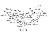
図2は、回転機械10(図1に示す)で使用されるように図示した、例示的な構成部品80の概略斜視図である。図3は、構成部品80を、3−3線(図2に示す)に沿って見た概略断面図である。図4は、図3では部分4として示す、構成部品80の一部の概略斜視断面図である。図2〜図4を参照すると、構成部品80は、事前に選択された厚さ104を有する外壁94を備える。さらに、例示的な実施形態では、構成部品80は、内部に画定された少なくとも1つの内部空隙100を備える。たとえば回転機械10の動作中、内部空隙100に冷却液101が供給されて、構成部品80の温度が高温燃焼ガスの温度未満に維持されやすいようになっている。 FIG. 2 is a schematic perspective view of an
構成部品80は、構成部品材料78から形成されている。例示的な実施形態では、構成部品材料78は好適なニッケル基超合金である。代替実施形態では、構成部品材料78は、コバルト基超合金、鉄基合金、又はチタン基合金のうちの少なくとも1つである。他の代替実施形態では、構成部品材料78はセラミック基複合材(ceramic matrix composite:CMC)である。他の代替実施形態では、構成部品材料78は、本明細書に記載しているように構成部品80を機能させることができる、任意の好適な材料である。 The
例示的な実施形態では、構成部品80は、ロータブレード70又はステータベーン72のうちの一方である。代替実施形態では、構成部品80は、回転機械10の別の好適な構成部品である。さらに他の実施形態では、構成部品80は、高温環境に暴露される任意の用途における任意の構成部品である。 In an exemplary embodiment, the
例示的な実施形態では、ロータブレード70、又はステータベーン72は、正圧側面74、及び対向する負圧側面76を含む。正圧側面74及び負圧側面76はそれぞれ、前縁84から対向する後縁86まで延在している。さらに、ロータブレード70、又はステータベーン72は、根元端部88から対向する先端部90まで延在している。構成部品80の長手方向軸89は、根元端部88と先端部90との間に画定されている。代替実施形態では、ロータブレード70、又はステータベーン72は、本明細書に記載している事前に選択された外壁厚さとなるように形成できる、任意の好適な構成を有する。 In an exemplary embodiment, the rotor blade 70, or stator vane 72, comprises a positive
外壁94は、構成部品80の外面92と、外面92に対向する内面93とを少なくとも部分的に画定している。例示的な実施形態では、外壁94は、前縁84と後縁86との間で円周方向に延在し、また根元端部88と先端部90との間で、さらに長手方向に延在している。代替実施形態では、外壁94は、構成部品80をその意図する目的に沿って機能させることができる、任意の好適な程度まで延在している。外壁94は、構成部品材料78から形成されている。 The
また、少なくとも1つの内部空隙100は、外壁94の内部に画定された、少なくとも1つのプレナム110を含む。例示的な実施形態では、プレナム110はそれぞれ、根元端部88から先端部90の近くまで延在している。代替実施形態では、各プレナム110は、本明細書に記載しているように構成部品80を機能させることができる任意の好適な方法で、かつ任意の好適な程度まで、構成部品80内に延在している。 Also, at least one
たとえば、図4に示す実施形態では、構成部品80は、外壁94の内部に配置された内壁96を備え、また少なくとも1つのプレナム110は、内壁96及びその内部によって少なくとも部分的に画定されている。例示的な実施形態では、少なくとも1つのプレナム110は、内壁96によってそれぞれ画定された複数のプレナム110と、正圧側面74と負圧側面76との間に少なくとも部分的に延在している、少なくとも1つの隔壁95とを備える。たとえば、図示している実施形態では、隔壁95はそれぞれ、正圧側面74の外壁94から負圧側面76の外壁94まで延在している。代替実施形態では、少なくとも1つの隔壁95は、正圧側面74の内壁96から負圧側面76の内壁96まで延在している。付加的又は代替的に、少なくとも1つの隔壁95は、正圧側面74の内壁96から外壁94まで、かつ/又は負圧側面76の内壁96から外壁94まで延在している。他の代替実施形態では、少なくとも1つの内部空隙100は、任意の好適な方法で画定された、任意の好適な数のプレナム110を含む。内壁96は、構成部品材料78から形成されている。 For example, in the embodiment shown in FIG. 4, the
さらに、いくつかの実施形態では、内壁96の少なくとも一部は、外壁94の少なくとも一部に隣接して円周方向及び長手方向に延在し、そこから内壁96の少なくとも一部が離隔距離98だけ離隔され、その結果、少なくとも1つの内部空隙100が、内壁96と外壁94との間に画定された、少なくとも1つのチャンバ112をさらに含むことになる。例示的な実施形態では、この少なくとも1つのチャンバ112は、それぞれが外壁94、内壁96、及び少なくとも1つの隔壁95によって画定された、複数のチャンバ112を含む。代替実施形態では、少なくとも1つのチャンバ112は、任意の好適な方法で画定された、任意の好適な数のチャンバ112を含む。例示的な実施形態では、内壁96は厚さ107を有し、かつ自身を貫通する複数の開口部102を画定しており、その結果、チャンバ112がそれぞれ、少なくとも1つのプレナム110と流体連通することになる。 Further, in some embodiments, at least a portion of the
例示的な実施形態では、プレナム110を通って供給され、内壁96内に画定された開口部102を通って放出されて、外壁94の内面93へと向かう冷却液101によって、外壁94の効果的なインピンジメント冷却を促進するように、離隔距離98が選択されている。一例として、限定はしないが、離隔距離98は構成部品80に沿って円周方向及び/又は長手方向に変動し、これによって外壁94のそれぞれの部分に沿った局所冷却の要件を容易に満たすようにしている。代替実施形態では、任意の好適な方法で離隔距離98が選択されている。例示的な実施形態においても、外壁94の効果的なインピンジメント冷却を促進するように選択されたパターン103において、開口部102が配置されている。一例として、限定はしないが、パターン103は構成部品80に沿って円周方向及び/又は長手方向に変動し、これによって外壁94のそれぞれの部分に沿った局所冷却の要件を容易に満たすようにしている。代替実施形態では、任意の好適な方法でパターン103が選択されている。 In an exemplary embodiment, the
いくつかの実施形態では、開口部102がそれぞれ、冷却液101が開口部102を通り、インピンジメント噴流105で内面93に向かって放出されるような大きさ及び形状とされている。たとえば、開口部102はそれぞれ、実質的に円形又は卵形の断面を有する。代替実施形態では、開口部102はそれぞれ、本明細書に記載しているように開口部102を機能させることができる、任意の好適な形状及び大きさとされている。 In some embodiments, the
例示的な実施形態では、外壁94は構成部品80の動作負荷を実質的に支持している一方、内壁96及び/又は隔壁95は、支持する負荷がほんの少量である少なくとも1つの挿入バッフルによって形成されている。代替実施形態では、内壁96及び/又は隔壁95は外壁94と一体的に形成され、かつ/又は構成部品80の動作負荷の大部分をこれらが支持している。 In an exemplary embodiment, the
また例示的な実施形態では、外壁94は、構成部品80と高温ガス環境との境界を画定しており、またその厚さ104は、より厚い外壁を有する構成部品と比較して、その流れを減少させた冷却液101を使用することにより、外壁94の効果的な冷却を促進するように選択されている。代替実施形態では、外壁厚さ104は、構成部品80をその意図する目的に沿って機能させることができる、任意の好適な厚さである。特定の実施形態では、外壁厚さ104は外壁94に沿って変動している。代替実施形態では、外壁厚さ104は外壁94に沿って一定である。 Also in an exemplary embodiment, the
例示的な実施形態では、外壁94は、自身を貫通して延在している放出開口部99を含み、この放出開口部99は、構成部品80が稼働状態に入っても、コーティングシステム200(以下に記載)によって妨害されず、またチャンバ112から自身を通して冷却液101を放出し、これにより、以下に記載している適応冷却に加えて、外壁94の外部にベースラインフィルム冷却をもたらしている。代替実施形態では、外壁94は放出開口部99を含まず、少なくとも1つの内部空隙100が、少なくとも1つのチャンバ112と流体連通している少なくとも1つの戻り流路114をさらに含むことにより、この戻り流路114がそれぞれ、外壁94のインピンジメント冷却に使用される冷却液101を流す戻り液用流路を供給することになる。他の代替実施形態では、構成部品80は、放出開口部99及び戻り流路114の両方を含む。少なくとも1つの内部空隙100が、ロータブレード70又はステータベーン72のうちの一方である構成部品80を冷却するにあたり使用するプレナム110、チャンバ112、及び必要に応じて戻り流路114を含むものとして示しているが、代替実施形態では、構成部品80が、任意の好適な用途に使用される任意の好適な構成部品であり、また構成部品80をその意図する目的に沿って機能させることができる、任意の好適な数、タイプ、及び構成の内部空隙100を備えることを理解すべきである。たとえば、いくつかの実施形態では、構成部品80は、外壁94のインピンジメント冷却用に構成されていない。 In an exemplary embodiment, the
例示的な実施形態では、構成部品80は、外壁94の外面92に施されたコーティングシステム200をさらに備える。このコーティングシステム200は、外壁94を高温環境から保護するために選択された、少なくとも1つの材料から形成されている。たとえば、図7に関してより詳述しているように、コーティングシステム200は、外面92に隣接し、かつこれに接着するように構成された好適なボンドコート層と、このボンドコート層に隣接する1つ又は複数の好適な遮熱表層とを含む。代替実施形態では、コーティングシステム200は、層及び厚さを好適に組み合わせた任意のものが適用される、任意の好適な材料又は材料の組み合わせから形成されている。コーティングシステム200は、全厚さ204を有する。図示を明確にするために、図2ではコーティングシステム200を表示していない。 In an exemplary embodiment, the
たとえば動作中に、冷却液101は構成部品80の根元端部88を通って、プレナム110へと供給される。この冷却液が概ね先端部90に向かって流れるとき、冷却液101の噴流105は開口部102を通ってチャンバ112内へと押し流され、次いで外壁94の内面93に突き当たる。例示的な実施形態では、その後、使用済みの冷却液101は、外壁94及びコーティングシステム200を貫通して延在している放出開口部99を通って流れる。たとえば冷却液101は、妨害されない所定の放出開口部99を通って作動液内へと放出され、これにより、以下に記載している適応冷却に加えて、外面92及びコーティングシステム200のベースラインフィルム冷却が促進されるようになる。 For example, during operation, the
代替実施形態では、使用済みの冷却液101は戻り流路114へと送られ、次いで概して根元端部88に向かって流れ、その後構成部品80から退出する。いくつかのこのような実施形態では、少なくとも1つのプレナム110、少なくとも1つのチャンバ112、及び少なくとも1つの戻り流路114をこのように配置することで、回転機械10の冷却回路の一部を形成しており、その結果、使用済みの冷却液101が、燃焼器部16(図1に示す)の上流側で、回転機械10を通る作動液流に戻されることになる。他の代替実施形態では、構成部品80は戻り流路114及び放出開口部99の両方を備え、冷却液101の第1の部分は、燃焼器部16(図1に示す)の上流側で、回転機械10を通る作動液流に戻され、また冷却液101の第2の部分は、放出開口部99を通って作動液内へと放出され、これにより、外面92及びコーティングシステム200のベースラインフィルム冷却が促進されるようになる。プレナム110及びチャンバ112を通過するインピンジメント流と、必要に応じて放出開口部99を通過する放出流又は流路114を通過する戻り流とを、構成部品80がロータブレード70及び/又はステータベーン72である実施形態に関して記載しているが、プレナム110、チャンバ112、放出開口部99及び/又は戻り流路114から形成される回路は、回転機械10のあらゆる構成部品80に適しており、さらに他のあらゆる用途に使用されるあらゆる好適な構成部品80に適している。 In an alternative embodiment, the used
外壁94は、その内部に画定され、かつ自身を通って延在している複数の適応冷却開口部120を含む。より具体的には、適応冷却開口部120はそれぞれ、少なくとも1つのプレナム110と流体連通している第1の端部122から、外面92を通って外方に、第2の端部124まで延在している。例示的な実施形態では、第1の端部122は外壁94の内面93内に画定され、かつこの内面93を貫通して延在し、また少なくとも1つのチャンバ112を介して、少なくとも1つのプレナム110と流体連通している。代替実施形態では、この第1の端部122は、少なくとも1つのプレナム110と流体連通している外壁94内の任意の適切な位置に画定されている。たとえば、第1の端部122は、図11に関して本明細書に記載しているように、外壁94内で外面92に対してほぼ平行に延在している流路170と流体連通状態で連結されている。 The
いくつかの実施形態では、図4に示すように、第2の端部124は外壁94の外面92に画定され、かつこの外面92を貫通して延在しており、その結果、第2の端部124は、コーティングシステム200の厚さ204全体の下に隠れている。他の実施形態では、図7に関して本明細書に記載するように、第2の端部124はコーティングシステム200内に画定されており、これによって適応冷却開口部120がコーティングシステム200内へと部分的に延在するようにしている。いずれの場合でも、例示的な実施形態では、構成部品80が稼働状態に入ると、各適応冷却開口部120の第2の端部124は、コーティングシステム200の厚さ204の少なくとも一部によって、その下側で覆われ、その結果、適応冷却開口部120を介し、外壁94を通って冷却液101が放出される際、コーティングシステム200によってその少なくとも一部が妨害されるようになる。換言すれば、構成部品80が稼働状態に入ると、適応冷却開口部120は、コーティングシステム200によって少なくとも部分的に妨害されるようになる。いくつかのそのような実施形態では、コーティングシステム200は多孔質であり、これにより動作中、コーティングシステム200が適応冷却開口部120の上方で損傷していない場合でも、冷却液101の一部が適応冷却開口部120を通って漏れ、その結果、外壁94の外面92及びコーティングシステム200のベースラインフィルム冷却がさらに促進されるようになる。他のそのような実施形態では、コーティングシステム200は無孔質であり、これにより、コーティングシステム200が適応冷却開口部120の上方で損傷していない場合、コーティングシステム200により、適応冷却開口部120が効果的に行き止まり状になる。 In some embodiments, as shown in FIG. 4, the
また図4には、構成部品80の稼働中に、コーティングシステム200の少なくとも一部が剥離した状態の、例示的な剥離領域250を示している。図5は、例示的な剥離領域250を含む、構成部品80の外壁94の斜視図である。たとえば、領域250は、コーティングシステム200が回転機械10(図1に示す)の動作中に高温環境によって剥離するか、あるいは劣化すると形成される。いくつかの実施形態では、構成部品80は、回転機械10(図1に示す)のロータブレード70又はステータベーン72のうちの一方であり、剥離領域250は、構成部品80の前縁84に沿って形成される。代替実施形態では、構成部品80は、高温環境に暴露されるあらゆる用途におけるあらゆる構成部品であり、かつ/又は剥離領域250は、構成部品80上の任意の位置に形成される。 Further, FIG. 4 shows an
図4及び図5に示す実施形態では、コーティングシステム200の全厚さ204が剥離領域250から剥離しており、外面92が高温動作環境に直接暴露されている。代替実施形態では、厚さ204の一部のみが剥離領域250で剥離又は損傷している。たとえば、コーティングシステム200の表層は、図7及び図8に関して本明細書により詳述するように、剥離領域250で離層する。 In the embodiments shown in FIGS. 4 and 5, the
コーティングシステム200が損傷又は剥離することにより、外壁94、及び剥離領域250におけるコーティングシステム200の露出部分252の熱暴露が増大することになる。適応冷却開口部120により、剥離領域250で冷却の必要性が増大している状況に、構成部品80が適応できるようになる。より具体的には、コーティングシステム200が剥離すると、剥離領域250内の各適応冷却開口部120の第2の端部124は完全に妨害されない状態となり、冷却液101が、少なくとも1つのプレナム110から適応冷却開口部120を通って外壁94の外部へと流れるための流路を形成し、これにより、外壁94及び剥離領域250におけるコーティングシステム200の露出部分252に対し、まず構成部品80内の内部冷却回路によってもたらされる冷却に加えて、追加の局所冷却(たとえば、ボア冷却及び/又は外側フィルム冷却)がもたらされることになる。 Damage or delamination of the
適応冷却開口部120を通過する妨害されない流れは剥離領域250内でのみ発生するため、結果として生じる適応冷却応答は、剥離領域250の大きさ及び位置に応じて自己調整されている。特定の実施形態では、構成部品80の冷却液101の全流量は、剥離領域250が発生し得る可能性を考慮しなければならないが、その場合でも、構成部品80に使用される冷却液101の全流量要件は、外壁94のより広い領域上に常設の貫通開口部を含むように設計された類似の構成部品と比較して低下するものであり、これはなぜなら、冷却流の放出が、構成部品80の稼働中に形成される剥離領域250に適応的に制限されるためである。さらに、いくつかの実施形態では、適応冷却開口部120によってもたらされる冷却は、たとえば外壁94及び/又は領域250におけるコーティングシステム200の露出部分252の一体性を維持し、また剥離領域250の大きさの拡大を防止することにより、剥離事象の緩和を促進している。 Since the unobstructed flow through the
いくつかの実施形態では、例示的な実施形態における回転機械10(図1に示す)などの構成部品80が設置される本システムは、剥離領域250の発生に応答して、構成部品80に供給される冷却液101の少なくとも1つの特性を変更するように構成された、追加のサブシステムを備える。たとえば、いくつかのそのような実施形態では、本システムは、構成部品80の上流側に補助圧縮機60を備える。補助圧縮機60は、剥離領域250の適応冷却開口部120に供給するのに必要となる追加流に対応するために、少なくとも1つのプレナム110に供給される冷却液101の圧力、ひいては流量を増大させる。さらに、いくつかのそのような実施形態では、本システムは、補助圧縮機60の上流側にあり、冷却液101の温度を低下させるように構成された熱交換器62を備える。たとえば、冷却液101の温度を低下させる熱交換器62により、補助圧縮機60によってその後行われる冷却液101の圧縮が容易になり、かつ/又は構成部品80に供給される冷却液101の冷却効率が改善される。あるいは補助圧縮機60は、熱交換器62なしで使用される。 In some embodiments, the system, in which the
特定の実施形態では、補助圧縮機60、及び設置する場合は熱交換器62の動作は、本システムにおける複数の構成部品80の稼働時間に基づいて選択的に調整される。たとえば、その稼働時間に基づいて、構成部品80における一定のレベルの剥離又は他の損傷が想定され、補助圧縮機60及び熱交換器62は、想定されるレベルの損傷に応じて、冷却液101の流量及び/又は冷却効率を増大させるように調整される。あるいは、いくつかの実施形態では、補助圧縮機60及び熱交換器62は、本システムにおける少なくとも1つの好適な測定動作パラメータに基づいて能動的に制御される。たとえば、この少なくとも1つの測定動作パラメータの値に変動が検出された場合、閾値量の冷却液101が複数の構成部品の剥離領域250を通って流れ、またそれに応じて、補助圧縮機60及び熱交換器62が、冷却液101の流量及び/又は冷却効率を増大させるように、自動的に制御されることを示している。代替実施形態では、補助圧縮機60及び熱交換器62は、本明細書に記載しているように補助圧縮機60及び熱交換器62を機能させることができる、任意の好適な方法で操作されている。他の代替実施形態では、本システムは補助圧縮機60及び熱交換器62を備えない。 In certain embodiments, the operation of the
図4及び図5において、適応冷却開口部120をそれぞれ、第1の端部122から第2の端部124まで、外壁94にほぼ垂直となる方向に延在するように示しているが、特定の実施形態では、少なくとも1つの適応冷却開口部120の向きは、外壁94に垂直となる向き以外である。より具体的には、図6を参照すると、特定の実施形態では、少なくとも1つの適応冷却開口部120は、外壁94に垂直となる方向97に対して測定した場合、鋭角をなす向きに方向付けられている。そのような一実施形態を図6に示しており、これは、外壁94で使用できる適応冷却開口部120の例示的な配置150を表す概略斜視図である。図6では、図示を容易にするために、適応冷却開口部120の配置150を包囲する外壁94の一部が、破線と共に透過表示されている。 4 and 5, respectively, show that the
例示的な実施形態では、適応冷却開口部120はそれぞれ、以下でさらに述べているように、その回転方向は異なり得るが、法線方向97に対して測定した場合、同じ鋭角142をなす向きに方向付けられている。代替実施形態では、少なくとも1つの適応冷却開口部120の鋭角142は、適応冷却開口部120の別の鋭角142と大きさが異なっている。特定の実施形態では、鋭角142はそれぞれ、約30度〜約60度の範囲となるように選択されている。より具体的には、例示的な実施形態では、鋭角142はそれぞれ、約37度となるように選択されている。代替実施形態では、鋭角142はそれぞれ、本明細書に記載しているように適応冷却開口部120を機能させることができる、任意の好適な大きさとなるように選択されている。いくつかの実施形態では、鋭角142をなす向きに方向付けられた適応冷却開口部120により、剥離領域250(図5に示す)の露出部分252に沿った、コーティングシステム200の冷却の増大が促進される。より具体的には、いくつかのそのような実施形態では、鋭角142をなす向きに方向付けられた適応冷却開口部120は、露出部分252の縁部にほぼ平行となる法線方向97ではなく、少なくとも部分的に露出部分252に向かって冷却液101を送っている。たとえば、少なくとも部分的に露出部分252に冷却液101が送られることにより、露出部分252の冷却が増大し、これにより、コーティングシステム200が過熱してさらに剥離することが抑制される。 In an exemplary embodiment, each
例示的な実施形態では、配置150は、外壁94にわたって分散配置される適応冷却開口部120の繰返し群によって形成され(1つの群を示している)、当該群の適応冷却開口部120はそれぞれ、当該群の他の適応冷却開口部120とは異なる方向に、鋭角142だけ回転する。したがって、外面92のいずれに剥離領域250が形成されるかに関係なく、適応冷却開口部120の少なくとも1つは、少なくとも部分的にコーティングシステム200の露出部分252に向けられ、これにより、露出部分252の冷却の増大が促進され、その結果、剥離領域250の拡大が抑制されることになる。 In an exemplary embodiment, the
たとえば、図示の実施形態では、配置150の繰返し群はそれぞれ、外壁94の立方体部分における4つの各側面に配置された、4つの適応冷却開口部120を含む。当該群の適応冷却開口部120はそれぞれ、異なる方向に鋭角142だけ回転され、この回転方向は、当該群において隣接する適応冷却開口部120に対して、90度だけ進められる。その結果、各適応冷却開口部120の第1の端部122は、隣接する適応冷却開口部120の第2の端部124の真下に位置することになる。図示している配置150は、外面92のいずれに剥離領域250が形成されるかに関係なく、適応冷却開口部120の少なくとも1つがコーティングシステム200の露出部分252に少なくとも部分的に向けられるようにさらに促進する。代替実施形態では、配置150の各群は、本明細書に記載しているように配置150を機能させることができる、任意の好適な数及び向きの適応冷却開口部120を含む。 For example, in the illustrated embodiment, each repeating group of
代替実施形態では、各群の少なくともいくつかの適応冷却開口部120は、同じ方向に鋭角142だけ回転される。たとえばいくつかの実施形態では、外壁94は、回転機械10(図1に示す)を通過する作動液流の局所方向など、既知の概ね一致する外部流160(図5に示す)の方向に暴露されている。適応冷却開口部120はそれぞれ、第2の端部124が、接近する外部流160の方向に向かって少なくとも部分的に傾斜し、すなわち、少なくとも部分的に対向するように方向付けられている。したがって、剥離領域250が形成されると、適応冷却開口部120はそれぞれ、外部流方向160に対向する速度成分で、第2の端部124から冷却液101を流す。剥離領域250の露出部分252における前縁部分253及び後縁部分254で、接近する外部流の局所動的圧力が変動することにより、剥離領域250の中央部に方向付けられた適応冷却開口部120が流す冷却液101の流量が少なくなる一方、剥離領域250の露出部分252に最も近接した適応冷却開口部120が流す冷却液101の流量はより多くなり、再度コーティングシステム200の過熱及び剥離の促進を抑制することになる。 In an alternative embodiment, at least some
代替実施形態では、適応冷却開口部120は、本明細書に記載しているように適応冷却開口部120を機能させることができる、任意の好適な方法で方向付けられる。 In an alternative embodiment, the
図7は、構成部品80の外壁94に関する別の例示的な実施形態の概略断面図である。図8は、別の例示的な剥離領域250を含む、外壁94の概略断面図である。図示の実施形態では、コーティングシステム200は、外面92に隣接し、かつこれに接着するように構成されたボンドコート層210と、ボンドコート層210に隣接した少なくとも1つの追加層とを含む。より具体的には、例示的な実施形態では、コーティングシステム200は、ボンドコート層210に隣接し、かつ接着するように構成された中間層212と、この中間層212に隣接し、かつ接着するように構成された表層、すなわち断熱層214とをさらに含む。たとえば、例示的な実施形態では、ボンドコート層210は、Mが鉄、コバルト、若しくはニッケルであり、Yがイットリア若しくは別の希土類元素である、拡散アルミナイド又はMcrAlYを含むアルミニウムリッチ材料である。代替実施形態では、ボンドコート層210は、本明細書に記載しているようにボンドコート層210を機能させることができる、任意の好適な材料である。例示的な実施形態では、中間層212はイットリア安定化ジルコニアを含む。代替実施形態では、中間層212は、本明細書に記載しているように中間層212を機能させることができる、任意の好適な材料である。例示的な実施形態では、断熱層214は、たとえばジルコニウム基又はハフニウム基酸化物格子構造(ZrO2又はHfO2)、並びに酸化イッテルビウム(Yb2O3)、酸化イットリア(Y2O3)、酸化ハフニウム(HfO2)、酸化ランタン(La2O3)、酸化タンタル(Ta2O5)、若しくは酸化ジルコニウム(ZrO2)のうちの1つ又は複数を含む酸化安定剤化合物(酸化「ドーパント」とも呼ばれる)を含む、超低熱伝導率のセラミック材料である。代替実施形態では、断熱層214は、本明細書に記載しているように断熱層214を機能させることができる、任意の好適な材料である。代替実施形態では、コーティングシステム200は、任意の好適な数及びタイプの層を含む。 FIG. 7 is a schematic cross-sectional view of another exemplary embodiment with respect to the
上述のように、適応冷却開口部120はそれぞれ、少なくとも1つのプレナム110と流体連通している第1の端部122から、外面92を通って外方に、第2の端部124まで延在している。図7及び図8に示す実施形態では、第2の端部124はコーティングシステム200内に画定されており、これによって適応冷却開口部120がコーティングシステム200内へと部分的に延在するようにしている。構成部品80が稼働状態に入ると、適応冷却開口部120の第2の端部124は、非ゼロの深さ220を有するコーティングシステム200の一部によって、その下側で覆われる。 As mentioned above, each
例示的な実施形態では、第2の端部124がコーティングシステム200の表層又は断熱層214内に配置されることにより、適応冷却開口部120がボンドコート層210及び中間層212の全厚さ、並びに断熱層214の第1の内側部分216のみの厚さを通って延在することになり、またその結果、第2の端部124が、断熱層214の残りの、第2の外側部分218の深さ220によって、その下側で覆われることになる。したがって、図8に示すように、断熱層214の第2の部分218の深さ220と少なくとも等しい深さまで剥離領域250が形成されると、剥離領域250における各適応冷却開口部120の第2の端部124は完全に妨害されない状態となり、冷却液101が少なくとも1つのプレナム110から適応冷却開口部120を通って外壁94の外部へと流れるための流路を形成し、これにより、外壁94及び剥離領域250におけるコーティングシステム200の露出部分252に対し、構成部品80内の内部冷却回路によってもたらされる冷却に加えて、追加の局所冷却(たとえば、ボア冷却及び/又は外側フィルム冷却)がもたらされることになる。代替実施形態では、第2の端部124は、コーティングシステム200内で任意の好適な深さ220で画定され、かつ/又は本明細書に記載しているように適応冷却開口部120を機能させることができる、コーティングシステム200における任意の好適な層又はその内部で終端している。 In an exemplary embodiment, the
たとえば、いくつかの実施形態では、剥離領域250は、断熱層214の第1の部分216から断熱層214の第2の部分218が層間剥離を起こしたものとして発生する傾向があり、また第2の部分218の標準深さ220は、外壁94のそれぞれの領域に対して経験的に決定されてもよい。次に、外壁94の各領域における適応冷却開口部120の第2の端部124の設計位置が、その領域の標準深さ220に対応するように選択され、その結果、適応冷却開口部120が、外壁94のそれぞれの領域において最も多い初期の層間剥離深さで作動することになる。したがって、適応冷却開口部120の第2の端部124の深さは、たとえば外壁94及び/又は領域250におけるコーティングシステム200の残りの層の一体性を維持し、かつ/又は剥離領域250の大きさが拡大するのを防止することにより、初期の層間剥離事象の緩和を促進するように選択されている。代替実施形態では、第2の端部124の設計位置は、本明細書に記載しているように適応冷却開口部120を機能させることができる、任意の好適な方法で選択される。 For example, in some embodiments, the
代替実施形態では、第2の端部124は、ボンドコート層210と中間層212との界面に画定され、また中間層212及び断熱層214の第1の部分216は多孔質材料とされ、その結果、断熱層214において深さ220までの層間剥離又は剥離が発生することにより、上述のように、第2の端部124、多孔質中間層212、及び多孔質の第1の部分216を通ってコーティングシステム200の外部へと、冷却液101が流れることが可能になっている。他の代替実施形態では、第2の端部124の配置及びコーティングシステム200の少なくとも1つの層の多孔度は、該当する深さの剥離又は層間剥離事象が発生したことに応答して、適応冷却開口部120を通過する流れを増大させることができる、任意の好適な方法で選択される。たとえば、第2の端部124は、ボンドコート層210と中間層212との界面に画定され、また中間層212は多孔質材料とされ、その結果、断熱層214において全厚さの層間剥離又は剥離が発生することにより、上述のように、第2の端部124及び多孔質中間層212を通ってコーティングシステム200の外部へと、冷却液101が流れることが可能になっている。 In an alternative embodiment, the
図9は、図7に示す外壁94の例示的な製造段階を表す概略断面図である。例示的な実施形態では、第1の端部122から外面92まで延在している適応冷却開口部120の第1の部分は、コーティングシステム200を外壁94に添加する前に、まず外壁94に形成される。たとえば、構成部品80は、適応冷却開口部120を含まない外壁94でまず形成され、その後、適応冷却開口部120の第1の部分が、好適な機械加工法によって外壁94に形成される。別の実施例では、構成部品80は、その内部に画定される、適応冷却開口部120の第1の部分を含む外壁94でまず形成される。より具体的には、外壁94は、適応冷却開口部120の第1の部分をその内部に画定するように成形されたコアの周りに、溶融金属の構成部品材料78を鋳造することによって形成されるか、又は外壁94は積層造形法によって形成され、この積層造形法において、適応冷却開口部120は、連続的に蒸着されて外壁94を形成する、構成部品材料78の薄層内に画定されている。 FIG. 9 is a schematic cross-sectional view showing an exemplary manufacturing stage of the
いくつかの実施形態では、外面92上にコーティングシステム200を施す前又はその間に、各適応冷却開口部120の第2の端部124にキャップ230が配置され、これによってコーティングシステム200の少なくとも一部の下に適応冷却開口部120を画定している。例示的な実施形態では、キャップ230は、適応冷却開口部120の第1の部分に挿入される長方形の部材である。より具体的には、キャップ230はそれぞれ、対応する適応冷却開口部120の第1の部分に収容される大きさ及び形状の第1の端部232から、外面92より外方に延在する大きさ及び形状の第2の端部234まで延在することで、対応する適応冷却開口部120の第2の端部124を画定している。第2の端部234が外面92から延在する状態でキャップ230が配置された後、コーティングシステム200は、キャップ230付近及びこれにわたって外面92上に、好適な噴霧蒸着法を用いる連続層などにおいて施される。コーティングシステム200が選択された厚さ204に形成された後、各キャップ230の第2の端部234は、図9に示すように、コーティングシステム200内で深さ220となる、対応する適応冷却開口部120の第2の端部124を画定する。 In some embodiments, a cap 230 is placed at the
別の実施形態では、キャップ230は、コーティングシステム200の蒸着の各段階で、適応冷却開口部120が第2の端部124でキャップ230まで全て画定されるまで、各適応冷却開口部120の露出した外側端部上に配置される平坦なカバー又はブランケット(図示せず)である。他の代替実施形態では、キャップ230は、本明細書に記載しているように適応冷却開口部120を形成できるようにする、任意の好適な構造を有する。 In another embodiment, the cap 230 exposes each
いくつかの実施形態では、コーティングシステム200が形成された後、構成部品80が稼働状態に入る前に、キャップ230が外壁94から除去される。たとえば、キャップ230は、構成部品80が稼働状態に入る前に、好適な浸出法において構成部品80から除去できる材料から形成されている。別の実施例では、キャップ230は、構成部品80が稼働状態に入る前に、好適な加熱法において、構成部品80から溶融排出されるように構成された材料から形成されている。他の実施形態では、構成部品80が稼働状態に入る前にキャップ230は除去されず、むしろ剥離領域250(図8に示す)がキャップ230上に形成されるまで適所にとどまる。たとえばキャップ230は、キャップ230が剥離領域250に関連する高温環境に暴露されると急速に焼け落ち、かつ/又は飛散するように構成された材料から形成され、その結果として、上述したように、対応する適応冷却開口部120の第2の端部124は妨害されない状態となり、冷却液101が、少なくとも1つのプレナム110から適応冷却開口部120を通って外壁94の外部へと流れるための流路が形成されるようになる。 In some embodiments, the cap 230 is removed from the
図10は、適応冷却開口部120を含む外壁94に関する、別の例示的な実施形態の概略断面図である。適応冷却開口部120の断面積126は、法線方向97に対して垂直に画定されている。特定の実施形態では、断面積126は、第1の端部122と第2の端部124との間で概ね縮小している。たとえば、例示的な実施形態では、適応冷却開口部120は外壁94内にほぼ円錐台の形状を画定しており、その結果、断面積126がほぼ円形となり、また第1の端部122と第2の端部124との間で縮小することになる。代替実施形態では、適応冷却開口部120はそれぞれ、本明細書に記載しているように適応冷却開口部120を機能させることができる、任意の好適な形状を画定している。 FIG. 10 is a schematic cross-sectional view of another exemplary embodiment with respect to the
いくつかのそのような実施形態では、剥離領域250(図8に示す)が適応冷却開口部120上に形成されると、コーティングシステム200の漸次深部、及び場合によっては、外壁94が酸化する、すなわち「溶け落ちる」か、あるいは第2の端部124の深さ220よりも深くまで剥離する。断面積126は、第2の端部124を越えて第1の端部122に向かって概ね拡大するので、剥離領域250の深さが深さ220を超えて拡大することにより、それに応じて剥離領域250における適応冷却開口部120の露出断面積126が拡大し、そのために、適応冷却開口部120を通過する冷却液101の流出量が増加し、また適応フィルム冷却効果が高まることになる。いくつかのそのような実施形態では、適応冷却開口部120の形状は、コーティングシステム200及び/又は外壁94の劣化の深刻度(たとえば、幅又は深さ)に応じてもたらされるフィルム冷却の量を自動的に「調整」するような、断面積126の変動をもたらすように、事前に選択されている。たとえば、コーティングシステム200の露出部分252から材料が焼け落ちるか、又は飛散すると、コーティングシステム200のさらなる劣化を抑制するのに十分な冷却流が適応冷却開口部120から放出されるまで、断面積126が徐々に拡大していくことになる。 In some such embodiments, when the stripped area 250 (shown in FIG. 8) is formed on the
図11は、適応冷却開口部120の別の実施形態を含む、構成部品80の外壁94に関する別の実施形態の概略断面図である。図11の実施形態では、構成部品80は、内壁96及びチャンバ112を備えず、また外壁94は、インピンジメント冷却を受けるように構成された比較的薄い壁ではない。外壁94は、その内部に画定され、かつ外面92から深さ172まで外面92に対してほぼ平行に延在している少なくとも1つの流路170を含む。たとえば、少なくとも1つの流路170は、外面92に近接して自身を通して冷却液101を流して、外面92に冷却をもたらすように構成された、複数の好適なマイクロ流路170である。例示的な実施形態では、流路170はそれぞれ、外壁94内で、少なくとも1つのプレナム110と流路170の第1の端部171との間に画定された、対応するアクセス開口部174を介して、少なくとも1つのプレナム110と流体連通している。代替実施形態では、流路170はそれぞれ、本明細書に記載しているように流路170を機能させることができる、任意の好適な方法で、少なくとも1つのプレナム110と流体連通している。 FIG. 11 is a schematic cross-sectional view of another embodiment of the
特定の実施形態では、流路170は、流路170を画定している面に沿って、タービュレータ180を含む。タービュレータ180は、流路170内の冷却液101の流動場で乱流を導入及び/又は増大させて、熱伝達を促進するように構成されている。例示的な実施形態では、タービュレータ180は、流路170を画定している面に沿った一連の隆起部として実装されている。代替実施形態では、タービュレータ180は、流路170の断面積における窪み、リブ、他の変形、表面粗さ部、及び本明細書に記載しているようにタービュレータ180を機能させることができる、任意の好適な構造として実装されている。他の代替実施形態では、流路170はタービュレータ180を含まない。 In certain embodiments, the
例示的な実施形態では、流路170はそれぞれ、外面92及びコーティングシステム200を貫通して延在している第2の端部(図示せず)まで延在し、また冷却液101は、流路170の第2の端部を通って作動液内へと放出される。代替実施形態では、流路170はそれぞれ、冷却液101を別の場所、たとえば回転機械10内の閉冷却回路内などの場所へと戻す第2の端部(図示せず)まで延在している。 In an exemplary embodiment, the
ここでも、適応冷却開口部120はそれぞれ、少なくとも1つのプレナム110と流体連通している第1の端部122から、外面92を通って外方に、第2の端部124まで延在している。例示的な実施形態では、第1の端部122は流路170と交差し、かつこれと流体連通している。代替実施形態では、第1の端部122は、流路170及び/又はアクセス開口部174を介して少なくとも1つのプレナム110と流体連通している、外壁94における任意の好適な位置に画定されている。 Again, the
いくつかの実施形態では、第2の端部124は、上述したように、外壁94の外面92に画定され、かつこの外面92を貫通して延在している。他の実施形態では、第2の端部124はコーティングシステム200内に画定されており、これによって適応冷却開口部120がコーティングシステム200内へと部分的に延在し、かつコーティングシステム200内で深さ220において配置されるようにしている。両方の実施形態による実施例を図11に示している。どちらの場合でも、構成部品80が稼働状態に入ると、適応冷却開口部120の第2の端部124は、コーティングシステム200の少なくとも一部によって、その下側で覆われ、その結果、適応冷却開口部120を介して、冷却液101が外壁94から放出される可能性がなくなることになる。換言すれば、構成部品80が稼働状態に入ると、適応冷却開口部120は、ここでもコーティングシステム200によって行き止まり状になる。したがって、図8に示すように、剥離領域250が断熱層214における第2の部分218の深さ220と少なくとも等しい深さまで形成されると、上述したように、剥離領域250における各適応冷却開口部120の第2の端部124は妨害されない状態となり、冷却液101が、少なくとも1つのプレナム110から適応冷却開口部120を通って外壁94の外部へと流れるための流路が形成されるようになる。 In some embodiments, the
図11では、適応冷却開口部120をそれぞれ、第1の端部122から第2の端部124まで、外壁94にほぼ垂直となる方向97に延在するように示しているが、特定の実施形態では、少なくとも1つの適応冷却開口部120の向きは、ここでも外壁94に垂直となる向き以外となる。より具体的には、特定の実施形態では、少なくとも1つの適応冷却開口部120は、たとえば図6に関して上述したように、ここでも方向97に対して鋭角142をなす向きに方向付けられている。さらに、いくつかのそのような実施形態では、適応冷却開口部120の群は、図6に関して上述したように、配置150又は別の好適な配置において方向付けられ、これにより、たとえば剥離領域250の露出部分252に向けた冷却液101の送出が促進され、かつ/又は外部流方向160(図5に示す)に対向する速度成分での、第2の端部124からの冷却液101の送出が促進される。 FIG. 11 shows the
上述の実施形態により、少なくともいくつかの既知の冷却システムと比較して、内部冷却構成部品の外面の剥離又は他の劣化の緩和が改善されるようになる。具体的には、本明細書に記載している実施形態は、外面に配置されたコーティングシステムと、外壁に画定された複数の適応冷却開口部とを備える構成部品を含む。適応冷却開口部はそれぞれ、少なくとも1つのプレナムと流体連通している第1の端部から、外面を通って外方に、コーティングシステムの厚さの少なくとも一部によって、その下側で覆われている第2の端部まで延在しており、その結果、本構成部品が稼働状態に入ると、適応冷却開口部を通過する流れがコーティングシステムによって妨害されることになる。ひとたび稼働に入ると、たとえば剥離事象によってコーティングシステムに局所的な損傷が生じることにより、適応冷却開口部の第2の端部が露出し、内部冷却流路からの冷却液が、適応冷却開口部を通って本構成部品の外部へと流され、フィルム又はボアの局所冷却をもたらし、これによってたとえば剥離事象などが緩和される。また具体的には、いくつかの実施形態では、たとえば剥離事象が発生する場所がいずれであっても、少なくともいくつかの適応冷却開口部が剥離領域の縁部に向かって確実に角度付けされるようにすることで、これらの適応冷却開口部が、外壁内で剥離領域の拡大を抑制しやすいように方向付けされている。 The embodiments described above will improve the mitigation of exfoliation or other deterioration of the outer surface of the internal cooling components as compared to at least some known cooling systems. Specifically, embodiments described herein include components having a coating system disposed on the outer surface and a plurality of adaptive cooling openings defined on the outer wall. Each adaptive cooling opening is covered from the first end, which is in fluid communication with at least one plenum, outward through the outer surface, underneath it, by at least a portion of the thickness of the coating system. It extends to the second end where the component is operational and the flow through the adaptive cooling opening is obstructed by the coating system. Once in operation, the second end of the adaptive cooling opening is exposed and the coolant from the internal cooling channel is exposed to the adaptive cooling opening, for example due to local damage to the coating system due to a peeling event. It is flushed through to the outside of the component, resulting in local cooling of the film or bore, which alleviates, for example, peeling events. More specifically, in some embodiments, at least some adaptive cooling openings are reliably angled towards the edge of the detachment region, eg, wherever the detachment event occurs. By doing so, these adaptive cooling openings are oriented so as to facilitate the suppression of expansion of the detached area within the outer wall.
本明細書に記載している方法、システム、及び装置の例示的な技術的効果には、(a)内部冷却構成部品の外面及び/又は残りのコーティングに対する、遮熱コーティングの剥離若しくは他の劣化の影響を緩和するステップ、(b)剥離事象及び/又は他のコーティングシステムの層間剥離事象において最も多い局所深さの経験的測定に基づいて、コーティングシステムの初期厚さの下側にある適応冷却開口部の端部の深さを選択するステップ、又は(c)剥離領域の大きさ及び深さに基づいて、追加の局所冷却の流量を自動的に「調整」するステップのうちの少なくとも1つが含まれる。 Exemplary technical effects of the methods, systems, and equipment described herein include (a) exfoliation or other degradation of the thermal barrier coating on the outer surface and / or the remaining coating of the internal cooling component. Adaptive cooling underneath the initial thickness of the coating system, based on empirical measurements of the most common local depths in steps to mitigate the effects of (b) delamination events and / or other coating system delamination events. At least one of the steps of selecting the depth of the edge of the opening, or (c) automatically "adjusting" the flow of additional local cooling based on the size and depth of the peeled area. included.
適応冷却構成部品の例示的な実施形態を上記で詳述している。構成部品、並びにこのような構成部品を用いた方法及びシステムは、本明細書に記載している特定の実施形態に限定されるものではなく、むしろ、システムの構成部品及び/又は本方法のステップは、本明細書に記載している他の構成部品及び/又はステップから独立して、かつ別個に利用されてもよい。たとえば、これらの例示的な実施形態を、高温環境で構成部品を用いるように現在構成されている他の多くの用途において、実現及び利用することができる。 Exemplary embodiments of adaptive cooling components are detailed above. The components, as well as the methods and systems using such components, are not limited to the particular embodiments described herein, but rather the components of the system and / or the steps of the method. May be used independently and separately from the other components and / or steps described herein. For example, these exemplary embodiments can be realized and utilized in many other applications currently configured to use components in high temperature environments.
本開示の様々な実施形態における具体的な特徴を一部の図面には示してあって、他の図面には示していないが、これは単に便宜上のためである。本開示の原理によれば、図面の任意の特徴は、他の任意の図面における任意の特徴と組み合わせて参照及び/又は特許請求することができる。 Specific features of the various embodiments of the present disclosure are shown in some drawings and not in others, but for convenience only. According to the principles of the present disclosure, any feature of a drawing can be referenced and / or claimed in combination with any feature in any other drawing.
本明細書では、実施形態を開示するために実施例を用いており、最良の形態を含んでいる。また、いかなる当業者もこれらの実施形態を実施することができるように実施例を用いており、任意のデバイス又はシステムを製作かつ使用し、任意の組み込まれた方法を実行することを含んでいる。本開示の特許可能な範囲は、特許請求の範囲によって定義され、当業者が想到する他の実施例を含むことができる。このような他の実施例は、特許請求の範囲の文言と相違しない構造的要素を有する場合、又は特許請求の範囲の文言と実質的に相違しない同等な構造的要素を含む場合、特許請求の範囲内にあることが意図されている。 Examples are used herein to disclose embodiments and include the best embodiments. Also, any person skilled in the art will use the examples to enable them to implement these embodiments, including making and using any device or system and performing any embedded method. .. The patentable scope of the present disclosure is defined by the scope of claims and may include other embodiments conceived by those skilled in the art. Such other embodiments may be claimed if they have structural elements that do not differ substantially from the wording of the claims, or if they contain equivalent structural elements that do not substantially differ from the wording of the claims. It is intended to be within range.
4 部分
10 回転機械
12 吸気部
14 圧縮機部
16 燃焼器部
18 タービン部
20 排気部
22 ロータシャフト
24 燃焼器
36 ケーシング
40 圧縮機ブレード
42 圧縮機ステータベーン
60 補助圧縮機
62 熱交換器
70 ロータブレード
72 タービンステータベーン
74 正圧側面
76 負圧側面
78 構成部品材料
80 構成部品
84 前縁
86 後縁
88 根元端部
89 長手方向軸
90 先端部
92 外面
93 内面
94 外壁
95 隔壁
96 内壁
97 法線方向
98 離隔距離
99 放出開口部
100 内部空隙
101 冷却液
102 開口部
103 パターン
104 外壁厚さ
105 インピンジメント噴流
107 厚さ
110 プレナム
112 チャンバ
114 戻り流路
120 適応冷却開口部
122 第1の端部
124 第2の端部
126 断面積
142 鋭角
150 配置
160 外部流、外部流方向
170 流路
171 第1の端部
172 深さ
174 アクセス開口部
180 タービュレータ
200 コーティングシステム
204 厚さ
210 ボンドコート層
212 中間層
214 断熱層
216 第1の内側部分
218 第2の外側部分
220 深さ
230 キャップ
232 第1の端部
234 第2の端部
250 剥離領域
252 露出部分
253 前縁部分
254 後縁部分4
Claims (12)
Translated fromJapanese前記外壁(94)の内部に画定され、その中に冷却液(101)を収容するように構成された、少なくとも1つのプレナム(110)と、
前記外面(92)上に施されたコーティングシステム(200)であって、前記コーティングシステム(200)はある厚さ(204)を有する、コーティングシステム(200)と、
前記外壁(94)内に画定された複数の適応冷却開口部(120)であって、前記複数の適応冷却開口部(120)はそれぞれ、前記少なくとも1つのプレナム(110)と流体連通している第1の端部(122)から、前記外面(92)を通って外方に、前記コーティングシステム(200)の前記厚さ(204)の少なくとも一部によって、その下側で覆われている第2の端部(124)まで延在している、前記複数の適応冷却開口部(120)と
を備え、
前記コーティングシステム(200)が、ボンドコート層(210)と、少なくとも1つの追加層(212、214)とを含み、前記少なくとも1つの追加層(212、214)が中間層(212)と、表層(214)とを含み、前記第2の端部(124)が前記表層(214)内に配置されている、構成部品(80)。The outer wall (94) including the outer surface (92) and
With at least one plenum (110) defined inside the outer wall (94) and configured to contain the coolant (101) therein.
A coating system (200) applied on the outer surface (92), wherein the coating system (200) has a certain thickness (204).
A plurality of adaptive cooling openings (120) defined within the outer wall (94), each of which is in fluid communication with the at least one plenum (110). From the first end (122), outward through the outer surface (92), covered underneath by at least a portion of the thickness (204) of the coating system (200). With the plurality of adaptive cooling openings (120) extending to the end (124) of 2.
The coating system (200) includes a bond coat layer (210) and at least one additional layer (212, 214), wherein the at least one additional layer (212, 214) is an intermediate layer (212) and a surface layer. (214) and a said second end (124) thatare located in the surface layer (214) within the component (80).
請求項1に記載の構成部品(80)。An inner wall (96) defined inside the outer wall (94), wherein the inner wall (96) includes an opening (102) that is defined inside and penetrates itself, and at least one of the above. A plenum (110) is defined inside the inner wall (96), the inner wall (96), and at least one chamber (112) defined between the inner wall (96) and the outer wall (94). ), And the opening (102) impingement of the coolant (101) from the at least one plenum (110) through the at least one chamber (112) towards the outer wall (94). It is configured to send a jet (105) and the first end (122) is connected to the at least one chamber (112) in a fluid communication state.
The component (80) according to claim 1.
燃焼ガスを発生させるように構成された燃焼器部(16)と、
前記燃焼器部(16)から前記燃焼ガスを受け取り、前記燃焼ガスから機械的回転エネルギーを発生させるように構成されたタービン部(18)であって、前記回転機械(10)を通過する前記燃焼ガスの流路は、高温ガス流路を画定している、タービン部(18)と、
請求項1乃至9のいずれか1項に記載の構成部品(80)であって、前記構成部品(80)は前記高温ガス流路に近接している、構成部品(80)と
を備え、
前記複数の適応冷却開口部(120)の少なくとも1つの適応冷却開口部(120)の前記第2の端部(124)が前記外壁(94)上の作動液流の局所方向へと少なくとも部分的に傾斜するように、前記複数の適応冷却開口部(120)のうちの前記少なくとも1つの適応冷却開口部(120)が方向付けられ、その結果、前記少なくとも1つの適応冷却開口部(120)が、前記作動液流の局所方向に対向する速度成分で、前記第2の端部(124)から前記冷却液(101)を流すように構成されている、回転機械(10)。It is a rotary machine (10),
A combustor unit (16) configured to generate combustion gas, and
A turbine unit (18) configured to receive the combustion gas from the combustor unit (16) and generate mechanical rotational energy from the combustion gas, and the combustion passing through the rotating machine (10). The gas flow path is defined by the turbine section (18), which defines the high temperature gas flow path.
The component (80) according to any one of claims 1 to9 , wherein the component (80) includes a component (80) that is close to the high temperature gas flow path.
The second end (124) of at least one adaptive cooling opening (120) of the plurality of adaptive cooling openings (120) is at least partial towards a local direction of hydraulic fluid flow on the outer wall (94). The at least one adaptive cooling opening (120) of the plurality of adaptive cooling openings (120) is oriented so as to be inclined to, so that the at least one adaptive cooling opening (120) is oriented. the at a speed component opposite to the local direction of the working fluid flow, thatis configured to flow the cooling fluid (101) from said second end (124), rotary machine (10).
Applications Claiming Priority (1)
| Application Number | Priority Date | Filing Date | Title |
|---|---|---|---|
| PCT/US2017/056500WO2019074514A1 (en) | 2017-10-13 | 2017-10-13 | Coated components having adaptive cooling openings and methods of making the same |
Publications (2)
| Publication Number | Publication Date |
|---|---|
| JP2021508361A JP2021508361A (en) | 2021-03-04 |
| JP6972328B2true JP6972328B2 (en) | 2021-11-24 |
Family
ID=60268454
Family Applications (1)
| Application Number | Title | Priority Date | Filing Date |
|---|---|---|---|
| JP2020519999AActiveJP6972328B2 (en) | 2017-10-13 | 2017-10-13 | Coated components with adaptive cooling openings and methods of their manufacture |
Country Status (5)
| Country | Link |
|---|---|
| US (1) | US11352886B2 (en) |
| EP (1) | EP3695101B1 (en) |
| JP (1) | JP6972328B2 (en) |
| CN (1) | CN111356820A (en) |
| WO (1) | WO2019074514A1 (en) |
Cited By (1)
| Publication number | Priority date | Publication date | Assignee | Title |
|---|---|---|---|---|
| JP7463500B2 (en) | 2019-10-25 | 2024-04-08 | ゼネラル エレクトリック テクノロジー ゲゼルシャフト ミット ベシュレンクテル ハフツング | Coolant delivery via separate cooling circuits |
Families Citing this family (4)
| Publication number | Priority date | Publication date | Assignee | Title |
|---|---|---|---|---|
| US11215074B2 (en)* | 2019-07-08 | 2022-01-04 | General Electric Company | Oxidation activated cooling flow |
| US11480070B2 (en) | 2019-10-25 | 2022-10-25 | General Electric Company | Coolant delivery via an independent cooling circuit |
| US11454133B2 (en) | 2019-10-25 | 2022-09-27 | General Electric Company | Coolant delivery via an independent cooling circuit |
| CN113828754B (en)* | 2021-10-20 | 2025-05-02 | 东莞职业技术学院 | Die casting model core pin cooling device with adaptive cooling channel depth |
Family Cites Families (37)
| Publication number | Priority date | Publication date | Assignee | Title |
|---|---|---|---|---|
| US3698834A (en)* | 1969-11-24 | 1972-10-17 | Gen Motors Corp | Transpiration cooling |
| NO743382L (en)* | 1973-09-24 | 1975-04-21 | Gen Electric | |
| US4312186A (en)* | 1979-10-17 | 1982-01-26 | General Motors Corporation | Shingled laminated porous material |
| JPS6217307A (en)* | 1985-07-17 | 1987-01-26 | Natl Res Inst For Metals | Air-cooled blade |
| EP1076107B1 (en)* | 1999-08-09 | 2003-10-08 | ALSTOM (Switzerland) Ltd | Process of plugging cooling holes of a gas turbine component |
| US6511762B1 (en)* | 2000-11-06 | 2003-01-28 | General Electric Company | Multi-layer thermal barrier coating with transpiration cooling |
| US6749396B2 (en)* | 2002-06-17 | 2004-06-15 | General Electric Company | Failsafe film cooled wall |
| US7488156B2 (en)* | 2006-06-06 | 2009-02-10 | Siemens Energy, Inc. | Turbine airfoil with floating wall mechanism and multi-metering diffusion technique |
| US7556476B1 (en) | 2006-11-16 | 2009-07-07 | Florida Turbine Technologies, Inc. | Turbine airfoil with multiple near wall compartment cooling |
| EP2354453B1 (en)* | 2010-02-02 | 2018-03-28 | Siemens Aktiengesellschaft | Turbine engine component for adaptive cooling |
| US8647053B2 (en)* | 2010-08-09 | 2014-02-11 | Siemens Energy, Inc. | Cooling arrangement for a turbine component |
| US8727727B2 (en)* | 2010-12-10 | 2014-05-20 | General Electric Company | Components with cooling channels and methods of manufacture |
| US20120148769A1 (en) | 2010-12-13 | 2012-06-14 | General Electric Company | Method of fabricating a component using a two-layer structural coating |
| US8753071B2 (en)* | 2010-12-22 | 2014-06-17 | General Electric Company | Cooling channel systems for high-temperature components covered by coatings, and related processes |
| US8601691B2 (en)* | 2011-04-27 | 2013-12-10 | General Electric Company | Component and methods of fabricating a coated component using multiple types of fillers |
| US20130086784A1 (en)* | 2011-10-06 | 2013-04-11 | General Electric Company | Repair methods for cooled components |
| US20130101761A1 (en)* | 2011-10-21 | 2013-04-25 | General Electric Company | Components with laser cladding and methods of manufacture |
| US9249670B2 (en)* | 2011-12-15 | 2016-02-02 | General Electric Company | Components with microchannel cooling |
| US9435208B2 (en)* | 2012-04-17 | 2016-09-06 | General Electric Company | Components with microchannel cooling |
| US9234438B2 (en)* | 2012-05-04 | 2016-01-12 | Siemens Aktiengesellschaft | Turbine engine component wall having branched cooling passages |
| US9518317B2 (en) | 2012-05-11 | 2016-12-13 | General Electric Company | Method of coating a component, method of forming cooling holes and a water soluble aperture plug |
| EP2873806A1 (en)* | 2013-11-14 | 2015-05-20 | Siemens Aktiengesellschaft | A thermal barrier coating enhanced cooling arrangement for a turbomachine component |
| US9476306B2 (en)* | 2013-11-26 | 2016-10-25 | General Electric Company | Components with multi-layered cooling features and methods of manufacture |
| US10731857B2 (en)* | 2014-09-09 | 2020-08-04 | Raytheon Technologies Corporation | Film cooling circuit for a combustor liner |
| EP3061556B1 (en)* | 2015-02-26 | 2018-08-15 | Rolls-Royce Corporation | Method for repairing a dual walled metallic component using braze material and such component obtained |
| US9752440B2 (en)* | 2015-05-29 | 2017-09-05 | General Electric Company | Turbine component having surface cooling channels and method of forming same |
| US9938899B2 (en)* | 2015-06-15 | 2018-04-10 | General Electric Company | Hot gas path component having cast-in features for near wall cooling |
| US9897006B2 (en)* | 2015-06-15 | 2018-02-20 | General Electric Company | Hot gas path component cooling system having a particle collection chamber |
| US20170130589A1 (en)* | 2015-11-05 | 2017-05-11 | General Electric Company | Article, component, and method of cooling a component |
| US10443508B2 (en)* | 2015-12-14 | 2019-10-15 | United Technologies Corporation | Intercooled cooling air with auxiliary compressor control |
| US10458251B2 (en)* | 2016-04-15 | 2019-10-29 | General Electric Company | Airfoil cooling using non-line of sight holes |
| US10704395B2 (en)* | 2016-05-10 | 2020-07-07 | General Electric Company | Airfoil with cooling circuit |
| US10415396B2 (en)* | 2016-05-10 | 2019-09-17 | General Electric Company | Airfoil having cooling circuit |
| US10689984B2 (en)* | 2016-09-13 | 2020-06-23 | Rolls-Royce Corporation | Cast gas turbine engine cooling components |
| US10612391B2 (en)* | 2018-01-05 | 2020-04-07 | General Electric Company | Two portion cooling passage for airfoil |
| US10774656B2 (en)* | 2018-04-09 | 2020-09-15 | General Electric Company | Turbine airfoil multilayer exterior wall |
| US10995621B2 (en)* | 2018-11-06 | 2021-05-04 | General Electric Company | Turbine airfoil with multiple walls and internal thermal barrier coating |
- 2017
- 2017-10-13JPJP2020519999Apatent/JP6972328B2/enactiveActive
- 2017-10-13CNCN201780096760.9Apatent/CN111356820A/enactivePending
- 2017-10-13USUS16/754,302patent/US11352886B2/enactiveActive
- 2017-10-13WOPCT/US2017/056500patent/WO2019074514A1/ennot_activeCeased
- 2017-10-13EPEP17794822.1Apatent/EP3695101B1/enactiveActive
Cited By (1)
| Publication number | Priority date | Publication date | Assignee | Title |
|---|---|---|---|---|
| JP7463500B2 (en) | 2019-10-25 | 2024-04-08 | ゼネラル エレクトリック テクノロジー ゲゼルシャフト ミット ベシュレンクテル ハフツング | Coolant delivery via separate cooling circuits |
Also Published As
| Publication number | Publication date |
|---|---|
| EP3695101B1 (en) | 2024-11-27 |
| JP2021508361A (en) | 2021-03-04 |
| US20200240273A1 (en) | 2020-07-30 |
| CN111356820A (en) | 2020-06-30 |
| US11352886B2 (en) | 2022-06-07 |
| EP3695101A1 (en) | 2020-08-19 |
| WO2019074514A1 (en) | 2019-04-18 |
Similar Documents
| Publication | Publication Date | Title |
|---|---|---|
| JP6972328B2 (en) | Coated components with adaptive cooling openings and methods of their manufacture | |
| US6905302B2 (en) | Network cooled coated wall | |
| EP1375825B1 (en) | Failsafe film cooled wall | |
| CN102562176B (en) | For providing method and the high-temperature component of fluid cooling system in high-temperature component | |
| EP1655454B1 (en) | Coated wall with cooling arrangement | |
| US6461107B1 (en) | Turbine blade tip having thermal barrier coating-formed micro cooling channels | |
| EP3063389B1 (en) | Bore-cooled film dispensing pedestals | |
| EP2574726B1 (en) | Airfoil and corresponding method of manufacturing | |
| EP1321629A2 (en) | Ventilated thermal barrier coating | |
| EP3460191B1 (en) | Gas turbine engine component with cooling holes having variable roughness | |
| EP3106618A1 (en) | Hot gas path component cooling system having a particle collection chamber | |
| JP5271688B2 (en) | Gas turbine components | |
| EP3351729A1 (en) | Gas turbine engine component and corresponding gas turbine engine | |
| JP2025051626A (en) | Title: TURBOMACHINE COMPONENT HAVING HOODED FILM COOLING HOLES EXPANDING FROM AN EXTERNAL WALL SURFACE | |
| KR20190083974A (en) | Method of forming cooling passage for turbine component with cap element | |
| EP2725120A1 (en) | High temperature components with thermal barrier coatings for gas turbine | |
| WO2019141755A1 (en) | Cooling concept for a turbine component | |
| EP2857637A1 (en) | Turbine airfoil and corresponding method of manufacturing | |
| KR101866900B1 (en) | Gas turbine blade | |
| JP5550699B2 (en) | Gas turbine components | |
| US20190316479A1 (en) | Air seal having gaspath portion with geometrically segmented coating |
Legal Events
| Date | Code | Title | Description |
|---|---|---|---|
| RD04 | Notification of resignation of power of attorney | Free format text:JAPANESE INTERMEDIATE CODE: A7424 Effective date:20200806 | |
| A521 | Request for written amendment filed | Free format text:JAPANESE INTERMEDIATE CODE: A523 Effective date:20201001 | |
| A621 | Written request for application examination | Free format text:JAPANESE INTERMEDIATE CODE: A621 Effective date:20201001 | |
| A521 | Request for written amendment filed | Free format text:JAPANESE INTERMEDIATE CODE: A523 Effective date:20210107 | |
| A521 | Request for written amendment filed | Free format text:JAPANESE INTERMEDIATE CODE: A523 Effective date:20210115 | |
| RD02 | Notification of acceptance of power of attorney | Free format text:JAPANESE INTERMEDIATE CODE: A7422 Effective date:20210115 | |
| A977 | Report on retrieval | Free format text:JAPANESE INTERMEDIATE CODE: A971007 Effective date:20210617 | |
| A131 | Notification of reasons for refusal | Free format text:JAPANESE INTERMEDIATE CODE: A131 Effective date:20210625 | |
| A521 | Request for written amendment filed | Free format text:JAPANESE INTERMEDIATE CODE: A523 Effective date:20210924 | |
| TRDD | Decision of grant or rejection written | ||
| A01 | Written decision to grant a patent or to grant a registration (utility model) | Free format text:JAPANESE INTERMEDIATE CODE: A01 Effective date:20211005 | |
| A61 | First payment of annual fees (during grant procedure) | Free format text:JAPANESE INTERMEDIATE CODE: A61 Effective date:20211102 | |
| R150 | Certificate of patent or registration of utility model | Ref document number:6972328 Country of ref document:JP Free format text:JAPANESE INTERMEDIATE CODE: R150 | |
| S111 | Request for change of ownership or part of ownership | Free format text:JAPANESE INTERMEDIATE CODE: R313113 | |
| R350 | Written notification of registration of transfer | Free format text:JAPANESE INTERMEDIATE CODE: R350 | |
| R250 | Receipt of annual fees | Free format text:JAPANESE INTERMEDIATE CODE: R250 |