JP6970553B2 - Image processing device, image processing method - Google Patents
Image processing device, image processing methodDownload PDFInfo
- Publication number
- JP6970553B2 JP6970553B2JP2017157618AJP2017157618AJP6970553B2JP 6970553 B2JP6970553 B2JP 6970553B2JP 2017157618 AJP2017157618 AJP 2017157618AJP 2017157618 AJP2017157618 AJP 2017157618AJP 6970553 B2JP6970553 B2JP 6970553B2
- Authority
- JP
- Japan
- Prior art keywords
- image processing
- representative position
- image
- class
- recognition
- Prior art date
- Legal status (The legal status is an assumption and is not a legal conclusion. Google has not performed a legal analysis and makes no representation as to the accuracy of the status listed.)
- Active
Links
Images


Classifications
- G—PHYSICS
- G06—COMPUTING OR CALCULATING; COUNTING
- G06F—ELECTRIC DIGITAL DATA PROCESSING
- G06F18/00—Pattern recognition
- G06F18/20—Analysing
- G06F18/23—Clustering techniques
- G—PHYSICS
- G06—COMPUTING OR CALCULATING; COUNTING
- G06V—IMAGE OR VIDEO RECOGNITION OR UNDERSTANDING
- G06V10/00—Arrangements for image or video recognition or understanding
- G06V10/70—Arrangements for image or video recognition or understanding using pattern recognition or machine learning
- G06V10/82—Arrangements for image or video recognition or understanding using pattern recognition or machine learning using neural networks
- G—PHYSICS
- G06—COMPUTING OR CALCULATING; COUNTING
- G06F—ELECTRIC DIGITAL DATA PROCESSING
- G06F18/00—Pattern recognition
- G06F18/20—Analysing
- G06F18/21—Design or setup of recognition systems or techniques; Extraction of features in feature space; Blind source separation
- G06F18/214—Generating training patterns; Bootstrap methods, e.g. bagging or boosting
- G—PHYSICS
- G06—COMPUTING OR CALCULATING; COUNTING
- G06F—ELECTRIC DIGITAL DATA PROCESSING
- G06F18/00—Pattern recognition
- G06F18/20—Analysing
- G06F18/21—Design or setup of recognition systems or techniques; Extraction of features in feature space; Blind source separation
- G06F18/217—Validation; Performance evaluation; Active pattern learning techniques
- G—PHYSICS
- G06—COMPUTING OR CALCULATING; COUNTING
- G06F—ELECTRIC DIGITAL DATA PROCESSING
- G06F18/00—Pattern recognition
- G06F18/20—Analysing
- G06F18/24—Classification techniques
- G06F18/241—Classification techniques relating to the classification model, e.g. parametric or non-parametric approaches
- G06F18/2413—Classification techniques relating to the classification model, e.g. parametric or non-parametric approaches based on distances to training or reference patterns
- G06F18/24133—Distances to prototypes
- G06F18/24137—Distances to cluster centroïds
- G06F18/2414—Smoothing the distance, e.g. radial basis function networks [RBFN]
- G—PHYSICS
- G06—COMPUTING OR CALCULATING; COUNTING
- G06N—COMPUTING ARRANGEMENTS BASED ON SPECIFIC COMPUTATIONAL MODELS
- G06N20/00—Machine learning
- G—PHYSICS
- G06—COMPUTING OR CALCULATING; COUNTING
- G06N—COMPUTING ARRANGEMENTS BASED ON SPECIFIC COMPUTATIONAL MODELS
- G06N3/00—Computing arrangements based on biological models
- G06N3/02—Neural networks
- G06N3/04—Architecture, e.g. interconnection topology
- G06N3/045—Combinations of networks
- G—PHYSICS
- G06—COMPUTING OR CALCULATING; COUNTING
- G06N—COMPUTING ARRANGEMENTS BASED ON SPECIFIC COMPUTATIONAL MODELS
- G06N3/00—Computing arrangements based on biological models
- G06N3/02—Neural networks
- G06N3/04—Architecture, e.g. interconnection topology
- G06N3/0464—Convolutional networks [CNN, ConvNet]
- G—PHYSICS
- G06—COMPUTING OR CALCULATING; COUNTING
- G06N—COMPUTING ARRANGEMENTS BASED ON SPECIFIC COMPUTATIONAL MODELS
- G06N3/00—Computing arrangements based on biological models
- G06N3/02—Neural networks
- G06N3/08—Learning methods
- G06N3/084—Backpropagation, e.g. using gradient descent
- G—PHYSICS
- G06—COMPUTING OR CALCULATING; COUNTING
- G06N—COMPUTING ARRANGEMENTS BASED ON SPECIFIC COMPUTATIONAL MODELS
- G06N3/00—Computing arrangements based on biological models
- G06N3/02—Neural networks
- G06N3/08—Learning methods
- G06N3/09—Supervised learning
- G—PHYSICS
- G06—COMPUTING OR CALCULATING; COUNTING
- G06T—IMAGE DATA PROCESSING OR GENERATION, IN GENERAL
- G06T7/00—Image analysis
- G06T7/70—Determining position or orientation of objects or cameras
- G06T7/73—Determining position or orientation of objects or cameras using feature-based methods
- G—PHYSICS
- G06—COMPUTING OR CALCULATING; COUNTING
- G06V—IMAGE OR VIDEO RECOGNITION OR UNDERSTANDING
- G06V30/00—Character recognition; Recognising digital ink; Document-oriented image-based pattern recognition
- G06V30/10—Character recognition
- G06V30/19—Recognition using electronic means
- G06V30/191—Design or setup of recognition systems or techniques; Extraction of features in feature space; Clustering techniques; Blind source separation
- G06V30/19147—Obtaining sets of training patterns; Bootstrap methods, e.g. bagging or boosting
- G—PHYSICS
- G06—COMPUTING OR CALCULATING; COUNTING
- G06V—IMAGE OR VIDEO RECOGNITION OR UNDERSTANDING
- G06V30/00—Character recognition; Recognising digital ink; Document-oriented image-based pattern recognition
- G06V30/10—Character recognition
- G06V30/19—Recognition using electronic means
- G06V30/191—Design or setup of recognition systems or techniques; Extraction of features in feature space; Clustering techniques; Blind source separation
- G06V30/1916—Validation; Performance evaluation
- G—PHYSICS
- G06—COMPUTING OR CALCULATING; COUNTING
- G06V—IMAGE OR VIDEO RECOGNITION OR UNDERSTANDING
- G06V30/00—Character recognition; Recognising digital ink; Document-oriented image-based pattern recognition
- G06V30/10—Character recognition
- G06V30/19—Recognition using electronic means
- G06V30/191—Design or setup of recognition systems or techniques; Extraction of features in feature space; Clustering techniques; Blind source separation
- G06V30/19173—Classification techniques
- G—PHYSICS
- G06—COMPUTING OR CALCULATING; COUNTING
- G06V—IMAGE OR VIDEO RECOGNITION OR UNDERSTANDING
- G06V30/00—Character recognition; Recognising digital ink; Document-oriented image-based pattern recognition
- G06V30/10—Character recognition
- G06V30/19—Recognition using electronic means
- G06V30/192—Recognition using electronic means using simultaneous comparisons or correlations of the image signals with a plurality of references
- G06V30/194—References adjustable by an adaptive method, e.g. learning
Landscapes
- Engineering & Computer Science (AREA)
- Theoretical Computer Science (AREA)
- Physics & Mathematics (AREA)
- General Physics & Mathematics (AREA)
- Computer Vision & Pattern Recognition (AREA)
- Data Mining & Analysis (AREA)
- Evolutionary Computation (AREA)
- Artificial Intelligence (AREA)
- General Engineering & Computer Science (AREA)
- Multimedia (AREA)
- Software Systems (AREA)
- Life Sciences & Earth Sciences (AREA)
- Computing Systems (AREA)
- General Health & Medical Sciences (AREA)
- Health & Medical Sciences (AREA)
- Mathematical Physics (AREA)
- Biophysics (AREA)
- Computational Linguistics (AREA)
- Biomedical Technology (AREA)
- Molecular Biology (AREA)
- Databases & Information Systems (AREA)
- Bioinformatics & Cheminformatics (AREA)
- Bioinformatics & Computational Biology (AREA)
- Evolutionary Biology (AREA)
- Medical Informatics (AREA)
- Image Analysis (AREA)
- Information Retrieval, Db Structures And Fs Structures Therefor (AREA)
Description
Translated fromJapanese本発明は、画像認識に係る技術に関するものである。 The present invention relates to a technique relating to image recognition.
従来、対象物体を撮影したカラー画像やデプス画像から特徴やパターンを学習し、対象物体を認識する手法がある。このような手法では、特徴やパターンを学習するために、カラー画像やデプス画像に対して、人間がどの対象物体が写っているかを指定したり、対象物体が写っている位置や位置姿勢を指定する(以下では「ラベル付け」と称する)必要がある。学習にはこのようなデータを大量に用意しなければならないが、人間が全てのラベル付けを正確に行うのは難しいという問題がある。 Conventionally, there is a method of recognizing a target object by learning features and patterns from a color image or a depth image of the target object. In such a method, in order to learn features and patterns, a human can specify which target object is shown in a color image or depth image, and specify the position and position / orientation in which the target object is shown. (Hereafter referred to as "labeling"). A large amount of such data must be prepared for learning, but there is a problem that it is difficult for humans to perform all labeling accurately.
このような問題を解決するために、特許文献1のように、「現状の認識器による認識結果の修正」、「修正したデータを用いた認識器の学習・更新」を繰り返すことによって、認識器の精度を高めていく方法がある。 In order to solve such a problem, the recognizer is obtained by repeating "correction of the recognition result by the current recognizer" and "learning / updating of the recognizer using the corrected data" as in
しかしながら、対象物体が写っている位置や位置姿勢を認識する認識器の場合、画像内の大量の画素が認識結果として出力され得るため、人間が各認識結果を修正するコストが高いという問題がある。 However, in the case of a recognizer that recognizes the position and position / posture in which the target object is captured, there is a problem that it is costly for a human to correct each recognition result because a large number of pixels in the image can be output as the recognition result. ..
本発明はこのような問題に鑑みてなされたものであり、画像中の対象物体の位置の指定に係る負荷を軽減させるための技術を提供する。 The present invention has been made in view of such a problem, and provides a technique for reducing the load related to the designation of the position of the target object in the image.
本発明の一様態は、入力画像における対象物体の位置として認識器が認識した複数の認識位置に対してクラスタリングを行うことで1以上の代表位置を取得する取得手段と、
前記代表位置に対するユーザからの編集指示に応じて該代表位置を編集する編集手段と、
前記入力画像と前記代表位置とを前記認識器の学習に用いるための学習データとして保存する保存手段と
を備えることを特徴とする。The uniform state of the present invention includes an acquisition means for acquiring one or more representative positions by performing clustering on a plurality of recognition positions recognized by the recognizer as the position of the target object in the input image.
An editing means for editing the representative position in response to an editing instruction from the user for the representative position,
It is characterized by comprising a storage means for storing the input image and the representative position as learning data for use in learning of the recognizer.
本発明の構成によれば、画像中の対象物体の位置の指定に係る負荷を軽減させることができる。 According to the configuration of the present invention, it is possible to reduce the load related to the designation of the position of the target object in the image.
以下、添付図面を参照し、本発明の実施形態について説明する。なお、以下説明する実施形態は、本発明を具体的に実施した場合の一例を示すもので、特許請求の範囲に記載した構成の具体的な実施例の1つである。 Hereinafter, embodiments of the present invention will be described with reference to the accompanying drawings. In addition, the embodiment described below shows an example when the present invention is concretely implemented, and is one of the specific examples of the configuration described in the claims.
[第1の実施形態]
本実施形態に係る画像処理装置は、入力画像に対して認識器を用いて認識した対象物体の認識位置をクラスタリングし、該クラスタリングにより得られる該認識位置の代表位置をラベルとしてユーザの修正対象にするラベル付け機能を有するものである。このような機能により、ユーザは全ての認識位置を確認、修正する必要が無くなり、代表位置に基づくラベルを確認、修正すればよいため、ラベル付けの手間が低減される。ここで、ラベルとは、画像中の対象物体の位置または位置姿勢に関する情報を意味しており、ラベルは認識器を構築するための教師データに利用される。[First Embodiment]
The image processing apparatus according to the present embodiment clusters the recognition positions of the target objects recognized by using the recognizer with respect to the input image, and uses the representative position of the recognition positions obtained by the clustering as a label to be corrected by the user. It has a labeling function. With such a function, the user does not need to confirm and correct all the recognition positions, and the label based on the representative position can be confirmed and corrected, so that the labor of labeling is reduced. Here, the label means information regarding the position or position / posture of the target object in the image, and the label is used for teacher data for constructing a recognizer.
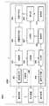
先ず、本実施形態に係る物体認識装置の機能構成例について、図1のブロック図を用いて説明する。図1に示す如く、本実施形態に係る物体認識装置1000は、撮像装置1、表示装置2、操作装置3、画像処理装置1100、を有する。 First, a functional configuration example of the object recognition device according to the present embodiment will be described with reference to the block diagram of FIG. As shown in FIG. 1, the
先ず、撮像装置1について説明する。撮像装置1は、静止画像若しくは動画像を撮像する装置である。撮像画像は特定の画像に限らず、カラー画像(例えばRGB画像)であっても良いし、モノクロ画像であっても良いし、赤外線画像であっても良いし、深度情報であるデプス画像であっても良い。撮像装置1によって撮像された撮像画像は画像処理装置1100に対して送出される。 First, the
次に、表示装置2について説明する。表示装置2は、CRTや液晶画面等により構成されており、画像処理装置1100による処理結果を画像や文字などでもって表示することができる。なお、表示装置2はタッチパネル画面であってもよく、この場合、タッチパネル画面に対するユーザからの各種の操作の内容は操作情報として画像処理装置1100に対して送出される。 Next, the
次に、操作装置3について説明する。操作装置3は、マウスやキーボードなどのユーザインターフェースにより構成されており、ユーザが操作することで各種の指示を画像処理装置1100に対して入力することができる。以下では、操作装置3はマウスであるものとして説明するが、以下に説明する同様の指示を画像処理装置1100に入力可能なユーザインターフェースであれば、如何なるユーザインターフェースを操作装置3に適用しても良い。 Next, the
次に、画像処理装置1100について説明する。画像取得部101は、撮像装置1から送出された撮像画像を取得する。なお、撮像画像の取得元は撮像装置1に限らず、LANやインターネットなどのネットワークを介してデータベース、サーバ装置、タブレット端末機器、スマートフォンなどの機器から撮像画像を取得するようにしても良い。然るに撮像画像は撮像装置1によって撮像された撮像画像であっても良いし、公開されている画像データベースに登録されている画像であっても良いし、Webにアップロードされている画像であっても良い。 Next, the
認識部102は先ず、認識器記憶部108に保存されているCNN(Convolutional Neural Network)(認識器)のモデル構造とCNNのパラメータとを用いてCNNを構成する。そして認識部102は、画像取得部101が取得した撮像画像に対して該構成したCNNを適用することで、該撮像画像における対象物体の位置を認識位置として認識する。 First, the
分類部103は、認識部102が認識した認識位置をクラスタリングすることで該認識位置を1以上のクラスに分類し、該クラスに属する認識位置に基づいて該クラスに対応する代表位置(ラベル)を求める(計算する)。 The
操作受付部104は、ユーザが操作装置3を操作したことで入力した操作内容に対応する命令を入力部105に送出する。入力部105は、操作受付部104から受けた命令に基づいて、上記の代表位置の編集(ラベル付け)を行う。そして入力部105は、撮像画像と代表位置とを上記のCNNの学習に用いる学習データとして記憶部106に格納する。 The
学習部107は、記憶部106に格納されている学習データを用いて教師データを作成する。そして学習部107は、認識器記憶部108に保存されているCNNのモデル構造とCNNのパラメータとを用いてCNNを構成し、上記作成した教師データを用いて、該構成したCNNのパラメータの学習処理を行う。そして学習部107は、認識器記憶部108に格納されているCNNのパラメータを、該学習処理によって得られたパラメータに更新する。 The
認識器記憶部108は、CNNのモデル構造やパラメータを保持している。本実施形態では、CNNのモデル構造は、撮像画像を入力とし、コンボリューション層や全結合層、Softmax層を経て、該撮像画像における各画像領域内に対象物体が写っているか否かの2クラス判別を出力するモデルとして設計されているとする。ここで、CNNのパラメータとは、コンボリューション層や全結合層内の各々の重みのことを指している。 The
制御部199は、画像取得部101、認識部102、分類部103、学習部107、操作受付部104、入力部105、の各機能部の動作制御を行うと共に、画像処理装置1100全体の動作制御を行う。 The
なお、図1では、撮像装置1、表示装置2、操作装置3、画像処理装置1100はそれぞれ別個の装置として示しているが、このうち2つ以上の機器を1つの機器に一体化させても良い。 Although the
次に、画像処理装置1100による物体認識処理について、図2(a)のフローチャートに従って説明する。ステップS1では、制御部199は、CNN(認識器)の学習が必要であるか否かを判断する。CNNの学習が必要であるか否かを判断する条件は特定の条件に限らない。例えば制御部199は、ユーザが操作装置3を操作してCNNの学習指示を入力したことを検知した場合には、CNNの学習が必要であると判断する。また、制御部199は、例えば、規定のタイミングごと若しくは規定の条件が満たされるたびに、CNNの学習が必要であると判断する。 Next, the object recognition process by the
このような判断の結果、CNNの学習が必要であると判断した場合には、処理はステップS2に進む。一方、CNNの学習が必要であると判断していない場合には、処理はステップS4に進む。 As a result of such a determination, if it is determined that learning of CNN is necessary, the process proceeds to step S2. On the other hand, if it is not determined that CNN learning is necessary, the process proceeds to step S4.
ステップS2では、上記のようにして学習データを生成して記憶部106に格納する。そしてステップS3では、学習データを用いて教師データを作成し、該教師データを用いてCNNのパラメータの学習を行い、認識器記憶部108に格納されているCNNのパラメータを該学習後のパラメータに更新する。 In step S2, the learning data is generated and stored in the
ステップS2及びS3における処理の詳細について、図2(b)のフローチャートに従って説明する。図2(b)においてステップS11〜S15が上記のステップS2において実行され、ステップS16,S17が上記のステップS3において実行される。 The details of the processing in steps S2 and S3 will be described according to the flowchart of FIG. 2B. In FIG. 2B, steps S11 to S15 are executed in the above step S2, and steps S16 and S17 are executed in the above step S3.
ステップS11では、画像取得部101は、撮像装置1から送出された撮像画像を取得する。ステップS12では、認識部102は先ず、認識器記憶部108に保存されているCNN(認識器)のモデル構造とCNNのパラメータとを用いてCNNを構成する。そして認識部102は、ステップS11で画像取得部101が取得した撮像画像に対して該構成したCNNを適用することで、該撮像画像における対象物体の位置を認識位置として認識する。 In step S11, the
例えば、画像取得部101が図3(a)に示す画像31を撮像画像として取得した場合、認識部102は、図3(b)に示す如く、画像31における着目画素位置32を中心とする画像領域33を設定する。画像領域33は着目画素位置32を含んでいれば良く、必ずしも着目画素位置32を中心とする画像領域であることに限らない。そして認識部102は、画像領域33内の画像を上記の構築したCNNに入力して該CNNの演算処理を行うことで、該CNNの出力を求める。そして認識部102は、CNNの出力が「画像領域33内に対象物体が写っている」ことを示す場合には、着目画素位置32を画像31における対象物体の位置(認識位置)と認識する。一方、認識部102は、CNNの出力が「画像領域33内に対象物体が写っている」ことを示していない場合には、着目画素位置32を画像31における対象物体の位置(認識位置)とは認識しない。認識部102は、着目画素位置32を点線34で示す如くラスタスキャン順で移動させながら各画素位置について同様の処理を行うことで、画像31上の各画素位置に対し、該画素位置を中心とする画像領域内に対象物体が写っているか否かを判断することができる。これにより、画像31上における対象物体の位置を認識することができる。なお、画像31上の各画素位置に対して、該画素位置を中心とする画像領域内に対象物体が写っているか否かを判断することができるのであれば、着目画素位置32の移動順はラスタスキャン順に限らない。 For example, when the
画像31中に写っているオブジェクトのうち円柱のオブジェクトを対象物体とした場合に、画像31上における対象物体の認識位置に「×」のマーカ(以下、認識位置マーカと称する)を付した結果を図3(c)に示す。近傍画素では似たような画像が切り抜かれることになるため、例えば認識位置マーカ群35で示す如く、認識位置が密集することが多い。また、対象物体と似たような特徴を持つ位置は誤認識が起こりやすい。たとえば、立方体はエッジ(画像中の輝度勾配)に囲まれている点で円柱と共通しているため、例えば認識位置マーカ群36で示す如く誤認識が起こることがある。 When a cylindrical object is used as the target object among the objects shown in the
ステップS13で分類部103は、ステップS12で認識部102が認識した対象物体の位置(認識位置)の集合を初期集合とし、規定のクラスタリング条件に基づいて該初期集合をクラスタリングすることで、該集合に含まれる認識位置を1以上のクラスに分類する。そして分類部103は、分類した1以上のクラスのそれぞれについて、該クラスに属する認識位置に基づいて該クラスに対応する代表位置を求める。例えば、初期集合を特徴としてKmeansアルゴリズムを用いて該初期集合をクラスタリングすると、近い認識位置が一つのクラスとしてまとめられる。そしてクラスごとに、該クラスに属する認識位置の平均位置を該クラスの代表位置とする。たとえば、図3(c)に示した認識位置マーカ群の位置をクラスタリングすると5つのクラスに分類される。この分類結果を図3(d)に示す。図3(d)では、分類された5つのクラスのそれぞれの位置(該クラスの代表位置)に「○」のマーカ(以下、代表位置マーカと称する)を付している。代表位置マーカ37は、認識位置マーカ群35に対応するクラスの代表位置に位置しており、代表位置マーカ38は、認識位置マーカ群36に対応するクラスの代表位置に位置している。なお、クラスタリングに必要なパラメータ(クラス数、クラスとしてまとめてよい範囲(クラス範囲)など)は、ユーザによって予め指定されており、分類部103が保持しているものとする。 In step S13, the
そして分類部103は、ステップS1で画像取得部101が取得した撮像画像上(入力画像上)の各クラスの代表位置に代表位置マーカを合成してから、該撮像画像を含む画面を表示装置2の表示画面に表示させる。この画面の表示例を図4に示す。画面41において表示領域42には、ステップS1で画像取得部101が取得した撮像画像が表示されており、この撮像画像上の各クラスの代表位置には代表位置マーカ401〜405が配されている。 Then, the
スライダ43は、クラスタリングに必要なパラメータを設定するためのものである。例えば、ユーザが操作装置3を操作してカーソル44をスライダ43の位置に移動させてからスライダ43の位置を変更する操作を行うことでスライダ43をより右端に近づけると、より大きいクラス数やより広いクラス範囲を指定することができる。また、ユーザが操作装置3を操作してカーソル44をスライダ43の位置に移動させてからスライダ43の位置を変更する操作を行うことでスライダ43をより左端に近づけると、より小さいクラス数やより狭いクラス範囲を指定することができる。現在指定されているクラス数やクラス範囲は領域43a内に数値として表示される。なお、領域43a内の数値をユーザが操作装置3を操作して直接指定することでクラス数やクラス範囲を設定しても良い。このように、クラス数やクラス範囲の指定方法は特定の指定方法に限らない。クラスタリングに必要なパラメータが新たに指定される度に分類部103は、該新たに指定されたパラメータを用いて上記初期集合をクラスタリングし、該クラスタリングにより得られる各クラスの代表位置に代表位置マーカを配置した撮像画像を表示領域42内に表示する。分類部103は、最新の代表位置のリスト(代表位置リスト)を管理している。なお、図4の画面は、本実施形態に適用可能な画面の一例であり、このような画面に限らない。 The
次に、ステップS14aでは、操作受付部104は、代表位置に係る編集操作入力(編集指示)を受け付ける。ユーザが操作装置3を操作して代表位置に係る編集の操作入力を行うと、操作受付部104は該編集の為の命令を作成して入力部105に入力する。 Next, in step S14a, the
ステップS14bでは、入力部105は、操作受付部104から命令を受け取ると、該命令に応じて、分類部103により分類された代表位置(ラベル)、つまり、上記の代表位置リストに登録されている代表位置に係る編集処理を行う。例えばユーザは操作装置3を操作して以下のような操作を行うことで、ラベルの削除、追加、修正、といったラベル付けを実現する。 In step S14b, when the
ここで、ユーザによるラベルの編集について、図5を用いて説明する。なお、以下に説明するユーザ操作に応じたラベルの編集処理は何れも、入力部105が行うものとする。 Here, the user's editing of the label will be described with reference to FIG. It should be noted that the
ユーザは操作装置3を操作してカーソル44を代表位置マーカ401〜405のうち所望の代表位置マーカの位置に移動させて、そこで右クリック操作を行うことで、該所望の代表位置マーカを削除することができる。代表位置マーカを削除すると、上記の代表位置リストから該代表位置マーカに対応する代表位置が削除される。例えば、図5(a)に示す如く、表示領域42内に表示されている撮像画像上に代表位置マーカ401〜405が配置されているとする。代表位置マーカ401〜405のうち代表位置マーカ401,403は円柱のオブジェクト、すなわち対象物体の位置を表している。しかし、代表位置マーカ402,404は円柱のオブジェクトではなく立方体のオブジェクトの位置を表しており、対象物体の位置を表していない。また、代表位置マーカ405はそもそも、オブジェクトの位置を表していない。このような場合、ユーザは操作装置3を操作してカーソル44を代表位置マーカ402,404,405のそれぞれの位置に移動させて、そこで右クリック操作を行うことで、該代表位置マーカを削除する。その結果、代表位置マーカのレイアウトは図5(a)から図5(b)のように変化する。図5(b)では、図5(a)の代表位置マーカ401〜405のうち代表位置マーカ402,404,405が削除されている。然るにこの場合、上記の代表位置リストから代表位置マーカ402,404,405のそれぞれに対応する代表位置が削除され、その結果、代表位置リストには、代表位置マーカ401,403に対応する代表位置のみが登録されている状態となっている。 The user operates the
図5(b)では、3つの対象物体のうち2つの対象物体のそれぞれには代表位置マーカ401,403が配されているが、残りの1つの対象物体406には代表位置マーカは配されていない。そこでユーザは操作装置3を操作してカーソル44を対象物体406の位置に移動させてから左クリック操作を行うことで、図5(c)に示す如く、該位置に新たな代表位置マーカ410を配置する。新たな代表位置マーカ410を配置した場合、上記の代表位置リストには、この代表位置マーカ410の配置位置が代表位置として登録される。 In FIG. 5B, the
また、ユーザは操作装置3を操作してカーソル44を所望の代表位置マーカの位置に移動させて、そこで左クリック操作を行いながらドラッグ&ドロップ操作を行うことで、該所望の代表位置マーカの位置を移動させることができる。代表位置マーカの位置を移動させると、上記の代表位置リストにおいて該代表位置マーカの位置が移動後の位置に変更される。図5(c)においてユーザが操作装置3を操作して代表位置マーカ403の位置を移動させた結果を図5(d)に示す。 Further, the user operates the
ステップS14cでは、制御部199は、ユーザが操作装置3を操作して終了ボタン45を指定したか否かを判断する。この判断の結果、ユーザが操作装置3を操作して終了ボタン45を指定した場合には、処理はステップS15に進む。一方、ユーザが操作装置3を操作して終了ボタン45を指定していない場合には、処理はステップS14aに進む。 In step S14c, the
ステップS15で入力部105は、代表位置リストと、ステップS11で画像取得部101が取得した撮像画像と、をCNNのパラメータの学習に用いる学習データとして記憶部106に格納する。また、分類部103は、図4の画面においてクラスタリングに必要なパラメータが変更された場合には、この変更されたパラメータを保持する。 In step S15, the
ステップS16では、学習部107は、記憶部106に格納されている学習データを用いて教師データを作成する。例えば学習部107は、認識部102と同様にして、学習データに含まれている撮像画像における各画素位置に対して画像領域を設定する。そして学習部107は、撮像画像における各画素位置に対し、該画素位置が該学習データに含まれている代表位置リストに登録されている代表位置の何れかに該当しているのか否か(正負(True、False))、を示す符号データを生成する。ここで、「AがBに該当している」とは、AとBとが全く同じであることに限らず、AとBとの差が規定値以内である、ことも含みうるものとする。学習部107は、学習データに含まれている撮像画像における着目画素位置が、該学習データに含まれている代表位置リストに登録されている代表位置の何れかに該当している場合には、該着目画素位置に対して符号データ「True」を割り当てる。一方、学習部107は、学習データに含まれている撮像画像における着目画素位置が、該学習データに含まれている代表位置リストに登録されている代表位置の何れにも該当していない場合には、該着目画素位置に対して符号データ「False」を割り当てる。そして学習部107は、撮像画像における画素位置ごとに、該画素位置に対して設定した画像領域内の画像(学習画像)と、該画素位置に割り当てた符号データと、を関連づけて保持する教師データを生成する。 In step S16, the
そして学習部107は、認識器記憶部108に保存されているCNNのモデル構造とCNNのパラメータとを用いてCNNを構成する。学習部107は、該構成したCNNにそれぞれの学習画像を入力することで得られる該CNNの出力が、該学習画像に対応する符号データとなるように、ディープラーニングで一般的に用いられている誤差逆伝播法でCNNのパラメータを最適化する。このときのCNNのパラメータの初期値として、認識器記憶部108に保存されているCNNのパラメータを用いる。 Then, the
ステップS17では、学習部107は、認識器記憶部108に格納されているCNNのパラメータを、ステップS16における学習(最適化)で得られたCNNのパラメータに更新する。 In step S17, the
図2(a)に戻って次に、ステップS4では、画像取得部101は、撮像装置1から送出された撮像画像を取得する。ステップS5では、認識部102は先ず、認識器記憶部108に保存されているCNN(認識器)のモデル構造とCNNのパラメータとを用いてCNNを構成する。そして認識部102は、ステップS4で画像取得部101が取得した撮像画像に対して該構成したCNNを適用することで、該撮像画像におけるオブジェクトの位置を認識位置として認識する。ステップS5において認識されたオブジェクトの認識位置の出力先は特定の出力先に限らない。例えば、図4の画面の表示領域42にステップS4で取得した撮像画像を表示すると共に、ステップS5で認識した認識位置若しくはその近傍位置にマーカ等の情報を配置しても良い。 Returning to FIG. 2A, in step S4, the
このように、本実施形態によれば、画像に対してラベル付けする際に、ユーザは現在の認識器で認識される代表位置を参考にラベル付けができるため、ユーザのラベル付けの手間が低減される。 As described above, according to the present embodiment, when labeling an image, the user can label the image with reference to the representative position recognized by the current recognizer, so that the user's labor for labeling is reduced. Will be done.
<第1の実施形態の変形例>
第1の実施形態では、ステップS13において、クラスタリングにKmeansアルゴリズムを用いた。しかし、クラスタリングのアルゴリズムは特定のアルゴリズムに限らない。例えば、Mean ShiftやNearest Neighborなどといった他のクラスタリングアルゴリズムを用いてもよいし、ユーザがひとつのクラスとしてまとめたい領域を、マウスで画像中をドラッグして指定してもよい。このようにすることで、まとめて処理する認識結果の領域を自由に調整することができる。<Modified example of the first embodiment>
In the first embodiment, the Kmeans algorithm was used for clustering in step S13. However, the clustering algorithm is not limited to a specific algorithm. For example, other clustering algorithms such as Mean Shift and Nearest Neighbor may be used, or the area that the user wants to combine as one class may be specified by dragging in the image with the mouse. By doing so, it is possible to freely adjust the area of the recognition result to be processed collectively.
また第1の実施形態では、ステップS13において、クラスに対応する代表位置として該クラスに属する認識位置の平均位置を用いたが、他の方法を用いて代表位置を算出しても良い。例えば、クラスに属する認識位置の中央値を該クラスの代表位置としても良いし、クラスに属する認識位置をガウス分布に当てはめた際のピーク位置を該クラスの代表位置としても良い。このようにすることで、クラスに属する認識位置にはずれ値などのノイズがあった場合でも、安定した代表位置を算出することができる。 Further, in the first embodiment, in step S13, the average position of the recognition positions belonging to the class is used as the representative position corresponding to the class, but the representative position may be calculated by using another method. For example, the median value of the recognition position belonging to the class may be used as the representative position of the class, or the peak position when the recognition position belonging to the class is applied to the Gaussian distribution may be used as the representative position of the class. By doing so, even if there is noise such as an outlier in the recognition position belonging to the class, a stable representative position can be calculated.
また第1の実施形態では、ステップS13において、撮像画像上に代表位置を示すマーカを配置したが、表示する情報はこれらの情報に限らず、例えば、代表位置を示すマーカだけでなく、認識位置を示すマーカも撮像画像上に合成して表示しても良いし、一部の対象物体の位置を撮像画像上に合成して表示しても良い。このようにすることで、ユーザは現状の認識器でどのような認識結果が得られているかが分かる。 Further, in the first embodiment, the marker indicating the representative position is arranged on the captured image in step S13, but the information to be displayed is not limited to these information, for example, not only the marker indicating the representative position but also the recognition position. The marker indicating the above may be combined and displayed on the captured image, or the position of a part of the target object may be combined and displayed on the captured image. By doing so, the user can know what kind of recognition result is obtained by the current recognizer.
また第1の実施形態では、ステップS14aにおいて、ラベル付けはユーザのマウス操作によって行った。しかし、他の方法でもってラベル付けを行っても良い。例えば、キーボードを用いた操作入力によってラベル付けを実施しても良いし、タッチパネルを用いた操作入力によってラベル付けを行っても良い。 Further, in the first embodiment, in step S14a, labeling was performed by a user's mouse operation. However, labeling may be performed by other methods. For example, labeling may be performed by operation input using a keyboard, or labeling may be performed by operation input using a touch panel.
また第1の実施形態では、ステップS14bでは、分類部103によって分類された代表位置を初期値とし、該初期値に対してラベル付けを行っていたが、これに限る必要はない。例えば、初期値は設定せず、代表位置を示す情報を合成した撮像画像を図4の画面とは別画面として表示することで、ユーザは代表位置を参考にラベル付けをしてもよい。また、図4の画面上に代表位置を半透明のマーカとして描画することで、ユーザは代表位置を参考にラベル付けをしてもよい。 Further, in the first embodiment, in step S14b, the representative position classified by the
[第2の実施形態]
本実施形態を含む以降の各実施形態や各変形例では、第1の実施形態との差分について説明し、以下で特に触れない限りは第1の実施形態と同様であるものとする。本実施形態に係る画像処理装置は、第1の実施形態に係る画像処理装置の機能に加え、各クラスに対する信頼度を算出し、該信頼度に応じてユーザによるラベル付けを行うのか否かを切り替える機能を有する。ユーザは信頼度が低い場合のみ、ラベルを確認、修正すればよいため、ラベル付けの手間が低減される。[Second Embodiment]
In each subsequent embodiment and each modification including the present embodiment, the difference from the first embodiment will be described, and the same as the first embodiment will be described unless otherwise specified below. The image processing apparatus according to the present embodiment calculates the reliability for each class in addition to the functions of the image processing apparatus according to the first embodiment, and determines whether or not the user labels according to the reliability. It has a switching function. Since the user only needs to check and correct the label when the reliability is low, the labor of labeling is reduced.
先ず本実施形態に係る物体認識装置の機能構成例について、図6のブロック図を用いて説明する。図6において図1に示した機能部と同じ機能部には同じ参照番号を付しており、該機能部に係る説明は省略する。本実施形態に係る物体認識装置2000は、画像処理装置2100の構成が図1の画像処理装置1100と異なる。 First, an example of the functional configuration of the object recognition device according to the present embodiment will be described with reference to the block diagram of FIG. In FIG. 6, the same functional unit as that shown in FIG. 1 is assigned the same reference number, and the description of the functional unit will be omitted. In the
分類部203は、分類部103の機能に加え、上記の代表位置リストと、認識部102が認識した認識位置の集合と、該認識位置がどのクラスに分類されたのかを示す情報と、を含む分類情報を生成して信頼度算出部209に送出する機能を有する。 In addition to the functions of the
信頼度算出部209は、クラスごとに、該クラスに属する認識位置の数に応じた信頼度を算出する。そして信頼度算出部209は、信頼度が閾値未満となるクラスの数が規定数(例えば1)以上である場合には、ユーザによるラベル付けが必要と判断し、その旨を入力部105に通知する。これにより入力部105は第1の実施形態と同様に、ユーザによるラベル付けの為の処理を行う。一方、信頼度算出部209は、信頼度が閾値未満となるクラスの数が規定数未満である場合、ユーザによるラベル付けは不必要と判断し、代表位置リストと、ステップS11で画像取得部101が取得した撮像画像と、を学習データとして記憶部106に格納する。 The
本実施形態に係るステップS2及びS3における処理の詳細について、図7のフローチャートに従って説明する。なお、図7において図2(b)に示した処理ステップと同じ処理ステップには同じステップ番号を付しており、該処理ステップに係る説明は省略する。図7においてステップS11〜S15が上記のステップS2において実行され、ステップS16,S17が上記のステップS3において実行される。 The details of the processes in steps S2 and S3 according to the present embodiment will be described with reference to the flowchart of FIG. 7. In FIG. 7, the same processing step as the processing step shown in FIG. 2B is assigned the same step number, and the description of the processing step will be omitted. In FIG. 7, steps S11 to S15 are executed in the above step S2, and steps S16 and S17 are executed in the above step S3.
ステップS23で分類部203は、上記のステップS13の処理を行うと共に、代表位置リストと、認識部102が認識した認識位置の集合と、該認識位置がどのクラスに分類されたのかを示す情報と、を含む分類情報を生成して信頼度算出部209に送出する。 In step S23, the
ステップS24aでは、信頼度算出部209は、クラスごとに、該クラスに属する認識位置の数に応じた信頼度を算出する。着目クラスの信頼度は、該着目クラスに属する認識位置の数が多いほど高く、少ないほど低くなるように算出する。例えば、着目クラスに属する認識位置の数を該着目クラスの信頼度として使用しても良い。例えば、図3(d)の代表位置マーカ37に対応するクラスの信頼度は、認識位置マーカ群35の認識位置の数である。 In step S24a, the
対象物体が確かに存在する位置の近傍画素では、対象物体近辺の画像が入力されるため、対象物体があるという判定がなされる確率が高い。一方、対象物体ではない位置は、たまたま対象物体と似たような特徴が抽出されてしまった場合に誤認識が起こる。この場合、前者よりも対象物体であると判定される確率は比較的に低い。以上の理由により、対象物体として認識された位置の数が多いほど信頼度が高いと考えられる。 Since the image in the vicinity of the target object is input to the pixels in the vicinity of the position where the target object certainly exists, there is a high probability that the determination that the target object exists is made. On the other hand, a position that is not a target object is erroneously recognized when a feature similar to that of the target object is extracted by chance. In this case, the probability of being determined to be the target object is relatively lower than that of the former. For the above reasons, it is considered that the higher the number of positions recognized as the target object, the higher the reliability.
そしてステップS24bでは、信頼度算出部209は、信頼度が閾値未満となるクラスの数を指標とし、該指標が規定数以上であるか否かを判断する。なお指標に適用可能なものは他にも考えられ、例えば、全クラス数に対する「信頼度が閾値未満となるクラスの数」の割合を指標として用いても良い。 Then, in step S24b, the
この判断の結果、指標が規定数以上である場合には、ユーザによるラベル付けが必要と判断し、処理はステップS14aに進む。一方、この判断の結果、指標が規定数未満である場合、信頼度算出部209は、ユーザによるラベル付けは不必要と判断し、処理はステップS15に進む。この場合、ステップS15では、信頼度算出部209は、代表位置リストと、ステップS11で画像取得部101が取得した撮像画像と、を学習データとして記憶部106に格納する。 As a result of this determination, if the index is equal to or greater than the specified number, it is determined that labeling by the user is necessary, and the process proceeds to step S14a. On the other hand, as a result of this determination, if the index is less than the specified number, the
このように、本実施形態によれば、新たな画像に対してラベル付けする際に、ユーザは現在の認識器で認識される代表位置の信頼度が低い場合のみラベル付けをすればよい。そのため、ラベル付けをしなければならない画像数が減少し、ユーザのラベル付けの手間が低減される。 As described above, according to the present embodiment, when labeling a new image, the user only needs to label the new image when the reliability of the representative position recognized by the current recognizer is low. Therefore, the number of images that must be labeled is reduced, and the user's labor for labeling is reduced.
<第2の実施形態の変形例>
第2の実施形態では、着目クラスの信頼度は、該着目クラスに属する認識位置の数が多いほど高く、少ないほど低くなるように算出したが、着目クラスの信頼度の求め方は特定の求め方に限らない。例えば、認識部102のCNNは、対象物体かどうかの確率として出力されるため、例えば、着目クラスに属する認識位置に対応するCNNの出力(確率)の合計値が高いほど該着目クラスの信頼度を高くし、該合計値が低いほど該着目クラスの信頼度を低くするようにしても良い。また、クラスに属する認識位置の数をそのまま該クラスの信頼度とするのではなく、対象物体かどうかの確率を重みとした線形和として信頼度を定義してもよいし、各認識位置の代表位置からの距離の逆数を重みとした線形和で信頼度を定義してもよい。<Modified example of the second embodiment>
In the second embodiment, the reliability of the focus class is calculated so that the larger the number of recognition positions belonging to the focus class, the higher the reliability, and the smaller the number, the lower the reliability. Not limited to one. For example, since the CNN of the
また、第2の実施形態では、ユーザによるラベル入力(代表位置の編集操作)が必要かどうかを判断するために信頼度と比較する閾値は予め定められた規定値であるものとしたが、これに限る必要はない。例えば、図4の画面においてユーザ操作に応じてこの閾値の値を設定できるようにしても良い。閾値はスライダを用いて設定しても良いし、テキスト入力によって設定しても良い。また、ラベルが変更された代表位置とラベルが変更されなかった代表位置のそれぞれの信頼度の統計をとることで閾値を求めてもよい。たとえば、ラベル変更が行われた代表位置の信頼度の平均値が10、ラベルが変更されなかった代表位置の信頼度の平均値が50であれば、その間の30を閾値とすれば良い。このようにすることで、ユーザが閾値を決める手間が低減される。 Further, in the second embodiment, the threshold value to be compared with the reliability in order to determine whether the label input (editing operation of the representative position) by the user is necessary is a predetermined predetermined value. It does not have to be limited to. For example, the value of this threshold value may be set according to the user operation on the screen of FIG. The threshold value may be set by using a slider or by text input. Further, the threshold value may be obtained by taking the statistics of the reliability of the representative position where the label is changed and the representative position where the label is not changed. For example, if the average value of the reliability of the representative position where the label is changed is 10 and the average value of the reliability of the representative position where the label is not changed is 50, 30 between them may be set as the threshold value. By doing so, the time and effort for the user to determine the threshold value is reduced.
また第2の実施形態では、ユーザによるラベル入力が必要ない場合、信頼度算出部209は、代表位置リストと、ステップS11で画像取得部101が取得した撮像画像と、を学習データとして記憶部106に格納していたが、これに限る必要はない。ユーザによるラベル入力が必要ない場合とは、現状の認識器で十分に認識できているため、例えば、学習データを記憶部106に格納することなく破棄してもよいし、ユーザに学習データとして追加するかどうかの判断を委ねてもよい。このようにすることで、一部の処理(主に学習部)が省略されるため、より早く一連の処理を終えられる。 Further, in the second embodiment, when the label input by the user is not required, the
また第2の実施形態では、ユーザによるラベル入力が必要な場合は、入力部105は、代表位置リストに登録されている全ての代表位置を編集候補として画面に表示して編集操作を受け付けていたが、これに限る必要はない。信頼度が閾値以上のクラスについてはラベル入力の必要はないため、入力部105は信頼度が閾値未満となるクラスの代表位置のみを編集候補として画面に表示して編集操作を受け付けるようにしてもよい。逆に、信頼度が極端に低い場合は誤認識と考えられるため、下限の閾値も設け、信頼度が下限の閾値以上で且つ上限の閾値(ステップS24bで使用した閾値)を下回るクラスの代表位置のみを編集候補として画面に表示して編集操作を受け付けるようにしてもよい。このようにすることで、ユーザが修正するラベル量が少なくなり、ユーザのラベル付けの手間が低減される。また、図4の画面に、各代表位置に対する信頼度を表す情報を表示するようにしても良い。信頼度を表す情報の表示としては、例えば、信頼度をテキスト表示しても良いし、信頼度に応じた色や形を有する規定のパターン画像を表示しても良いし、信頼度ごとに予め作成されたパターン画像を表示しても良い。これにより、ユーザがラベル付けする際に、代表位置をどの程度信用するかの参考になる。 Further, in the second embodiment, when the user needs to input a label, the
[第3の実施形態]
本実施形態に係る画像処理装置は、第1の実施形態に係る画像処理装置の機能に加え、学習後のCNNの性能の評価値を求め、該求めた評価値に応じて該CNNを更新するか否かを判断する機能を有する。評価値が高くなる場合のみCNNを更新することで、CNNの性能向上は加速し、より良い結果が得られるようになり、ユーザによるラベル修正量が少なくなるため、ラベル付けの手間が低減される。[Third Embodiment]
The image processing apparatus according to the present embodiment obtains an evaluation value of the performance of the CNN after learning in addition to the function of the image processing device according to the first embodiment, and updates the CNN according to the obtained evaluation value. It has a function to judge whether or not it is. By updating the CNN only when the evaluation value is high, the performance improvement of the CNN is accelerated, better results can be obtained, and the amount of label correction by the user is reduced, so that the labor of labeling is reduced. ..
先ず本実施形態に係る物体認識装置の機能構成例について、図8のブロック図を用いて説明する。図8において図1に示した機能部と同じ機能部には同じ参照番号を付しており、該機能部に係る説明は省略する。本実施形態に係る物体認識装置3000は、画像処理装置3100の構成が図1の画像処理装置1100と異なる。 First, an example of the functional configuration of the object recognition device according to the present embodiment will be described with reference to the block diagram of FIG. In FIG. 8, the same functional unit as that shown in FIG. 1 is assigned the same reference number, and the description of the functional unit will be omitted. In the
学習部307は、上記の学習部107の機能に加え、学習処理によって得られたCNNのパラメータを、評価部310にも送出する。評価部310は、認識器記憶部108に保存されているCNNのモデル構造及びパラメータに基づくCNN(旧CNN)の性能の評価値を、記憶部311に格納されているデータを用いて求める。更に評価部310は、学習部307から送出されたパラメータと認識器記憶部108に保存されているCNNのモデル構造とに基づくCNN(新CNN)の性能を評価するための評価値を、記憶部311に格納されているデータを用いて求める。記憶部311には、試験画像と、該試験画像における代表位置と、が試験データとして格納されている。 In addition to the functions of the
更新判定部312は、旧CNNの評価値と新CNNの評価値とを比較し、該比較の結果に基づいて、新CNNのパラメータを認識器記憶部108に格納するか否かを判断する。そして更新判定部312は、旧CNNの評価値よりも新CNNの評価値が高い場合には、新CNNのパラメータを認識器記憶部108に格納することで、認識器記憶部108が保持する旧CNNを新CNNに更新する。 The
本実施形態に係るステップS2及びS3における処理の詳細について、図9のフローチャートに従って説明する。図9においてステップS11〜S15が上記のステップS2において実行され、ステップS36〜S39が上記のステップS3において実行される。 The details of the processes in steps S2 and S3 according to the present embodiment will be described with reference to the flowchart of FIG. In FIG. 9, steps S11 to S15 are executed in the above step S2, and steps S36 to S39 are executed in the above step S3.
ステップS36では、学習部307は、上記のステップS16の処理を行うと共に、学習処理によって得られたCNNのパラメータを、評価部310にも送出する。 In step S36, the
ステップS37では、評価部310は、記憶部311に格納されているデータを用いて、旧CNNの評価値及び新CNNの評価値を求める。旧CNN及び新CNNのそれぞれの評価値を求める方法には様々な方法があり、特定の方法に限らない。以下にCNN(旧CNN及び新CNN)の評価値を求める方法の一例を説明する。 In step S37, the
先ず、評価部310は、記憶部311から試験データを取得する。試験データには、1つのオブジェクトが写っている試験画像と、該試験画像における該オブジェクトの位置である代表位置と、のセットが複数セット含まれているものとする。そして評価部310は、試験データに含まれている複数セットのうち未選択のセットを選択セットとして選択し、上記のステップS12と同様に、該選択セットに含まれている試験画像に対してCNNを適用することで該試験画像における認識位置を取得する。そして評価部310は、選択セットの試験画像から認識した全ての認識位置が、該選択セットに含まれている代表位置から規定距離以内にあれば成功と判断する。一方、評価部310は、選択セットの試験画像から認識した認識位置のうち1つでも、該選択セットに含まれている代表位置から規定距離以内になければ失敗と判断する。このような選択セットに対する成功/失敗の判断処理を、試験データに含まれている全てのセットについて行うことで、それぞれのセットについて成功/失敗を判断する。そして評価部310は、((成功と判断したセットの数)/全セット数)を評価値として求める。このような評価値を旧CNN及び新CNNのそれぞれについて求める。なお、上記の通り、このような評価値の算出方法は一例であり、他の算出方法を用いて評価値を算出しても良い。 First, the
ステップS38では、更新判定部312は、旧CNNの評価値と新CNNの評価値との大小比較を行う。この大小比較の結果、旧CNNの評価値<新CNNの評価値であれば、処理はステップS39に進み、旧CNNの評価値≧新CNNの評価値であれば、認識器記憶部108に格納されているパラメータの更新を行うことなく、図9のフローチャートに従った処理は終了する。ステップS39では、更新判定部312は、新CNNのパラメータを認識器記憶部108に格納することで、認識器記憶部108が保持するCNNを新CNNに更新する。 In step S38, the
このように、本実施形態によれば、新たな画像に対してラベル付けする際に、参考としてユーザに提示される代表位置の精度が向上していくため、ラベル修正量が少なくなり、ユーザのラベル付けの手間が低減される。 As described above, according to the present embodiment, when labeling a new image, the accuracy of the representative position presented to the user as a reference is improved, so that the amount of label correction is reduced and the user's The effort of labeling is reduced.
<第3の実施形態の変形例>
第3の実施形態では、上記のステップS1の処理は省いても良い。すなわち、評価部310によって、新CNNの評価値が算出されるため、評価値用閾値を設け、新CNNの評価値が評価値用閾値以上になるまで繰り返しCNNの学習を続けるようにしてもよい。また、何度も学習を行う中で、評価値の変化が規定値未満となった場合に、学習を終了するようにしてもよい。たとえば、評価値の変化が0.01%未満で5回続き、性能が飽和したと考えられるような場合に、学習を終了する。このようにすることで、ユーザが学習が必要かどうかを判断する手間が削減される。<Modified example of the third embodiment>
In the third embodiment, the process of step S1 may be omitted. That is, since the evaluation value of the new CNN is calculated by the
また、第3の実施形態では、入力部105は、撮像画像と代表位置とを常に記憶部106に格納していた。しかし、学習データだけでなく、試験データを増やす必要もあるため、画像と代表位置とのセットを記憶部106だけでなく記憶部311にも格納するようにしても良い。なお、画像と代表位置のセットは記憶部106と記憶部311の両方に格納するようにしても良いし、記憶部106と記憶部311のうちランダムに決まる一方に格納するようにしても良い。また、画像と代表位置のセットを記憶部106及び記憶部311の何れに格納するのかをユーザが操作装置3を操作して指定しても良い。 Further, in the third embodiment, the
また、第2の実施形態で説明した信頼度算出部209を画像処理装置3100に組み込んで、信頼度算出部209による信頼度に応じて画像と代表位置のセットを記憶部106及び記憶部311の何れに格納するのかを決定しても良い。たとえば、信頼度が閾値未満である代表位置と、対応する画像と、を記憶部106に格納し、信頼度が閾値以上である代表位置と、対応する画像と、を記憶部311に格納する。このようにすることで、学習データと試験データを効率よく収集することができる。 Further, the
また、ステップS38において、CNNの更新を行うか否かの判断だけでなく、新たに登録された学習データ(以下、新学習データ)を保持するかどうかの判断をしてもよい。CNNの性能が悪化したということは、新学習データのラベルに誤りが含まれている可能性が高いため、新学習データを破棄するようにしてもよい。または、新学習データのラベルが本当に正しいかを確認するため、ユーザに再度ラベル入力を要求してもよい。このようにすることで、ラベル誤りのある学習データを記憶する頻度を減らすことができる。 Further, in step S38, it may be determined not only whether or not to update the CNN, but also whether or not to retain the newly registered learning data (hereinafter referred to as new learning data). Since there is a high possibility that the label of the new training data contains an error because the performance of the CNN has deteriorated, the new training data may be discarded. Alternatively, the user may be required to enter the label again to confirm that the label of the new training data is really correct. By doing so, it is possible to reduce the frequency of storing training data having a label error.
また、第3の実施形態では、旧CNN及び新CNNの2つを評価していたが、これに限る必要はない。旧CNNは複数あってもよいし、新CNNも複数あってもよい。この場合、たとえば旧CNNは、旧CNNと新CNNのうち評価値が上位3つのCNNを認識器記憶部108に記憶するようにすればよい。また、たとえば新CNNは、初期値をランダムや旧CNNのいずれかにしたり、学習データをランダムに選択するなどして、複数種の学習結果が得られるようにすればよい。 Further, in the third embodiment, the old CNN and the new CNN were evaluated, but the present invention is not limited to this. There may be multiple old CNNs and multiple new CNNs. In this case, for example, the old CNN may store the three CNNs having the highest evaluation values among the old CNN and the new CNN in the
[第4の実施形態]
上記の各実施形態や各変形例では、新たに学習データが追加されるごとに学習を行っていたが、これに限る必要はない。例えば、複数セット(画像と代表位置のセット)が溜まってから学習を行ってもよいし、ユーザが学習を行うタイミングを操作装置3を操作して指定しても良い。[Fourth Embodiment]
In each of the above embodiments and modifications, learning is performed each time new learning data is added, but the learning is not limited to this. For example, learning may be performed after a plurality of sets (sets of images and representative positions) are accumulated, or the timing at which the user performs learning may be specified by operating the
また、上記の各実施形態や各変形例では、ディープラーニングの一種であるCNNを学習して認識器を構築したが、これに限る必要はない。特徴としては、LBP(Local Binary Pattern)を用いてもよいし、BoF(Bag of Features)などを用いてもよい。また、識別器としては、決定木を用いてもよいし、SVM(Support Vector Machine)などを用いてもよい。 Further, in each of the above embodiments and modifications, CNN, which is a kind of deep learning, is learned to construct a recognizer, but the present invention is not limited to this. As a feature, LBP (Local Binary Pattern) may be used, or BoF (Bag of Features) or the like may be used. Further, as the discriminator, a decision tree may be used, or an SVM (Support Vector Machine) or the like may be used.
また、上記の各実施形態や各変形例では、画像中の対象物体の位置のみを認識したが、これに限る必要はない。例えば、CNNの出力を対象物体かどうかの2クラス判別ではなく、姿勢の分類もするように出力を増やすことで、画像中の対象物体の位置姿勢を認識してもよい。以下、図10を用いて位置だけでなく姿勢も認識する場合の処理を説明する。 Further, in each of the above-described embodiments and modifications, only the position of the target object in the image is recognized, but the present invention is not limited to this. For example, the position and orientation of the target object in the image may be recognized by increasing the output so that the output of the CNN is not classified into two classes as to whether or not the object is the target object, but the posture is also classified. Hereinafter, the process of recognizing not only the position but also the posture will be described with reference to FIG.
図10(a)の×マーカ501は認識すべき対象物体の画像中の位置(x,y)を表しており、白抜き矢印502が該認識すべき対象物体の画像中の姿勢θ、黒矢印503は対象物体の姿勢を8姿勢に量子化した方向を示している。図10(a)のようにラベルを対象物体の位置姿勢(x,y,θ)として設定し、CNNを「8姿勢のうちどの姿勢の対象物体か」+「対象物体ではない」の9クラス判別するものとして設計する。 The
このようなCNNを作成して、第1の実施形態におけるステップS12と同様に認識を行うと、図10(b)のように、複数の位置姿勢の認識結果(認識位置姿勢)が得られる。図10(b)の×マーカ群504が認識された物体の位置群、白抜き矢印群505が認識された姿勢群を表している。 When such a CNN is created and recognition is performed in the same manner as in step S12 in the first embodiment, recognition results (recognition position posture) of a plurality of positions and postures can be obtained as shown in FIG. 10 (b). The
この認識結果を第1の実施形態におけるステップS13と同様に、クラスタリングを行って代表位置姿勢を求めてユーザに提示する。代表位置姿勢を求める際は、各対象物体の位置姿勢(x,y,θ)を特徴とし、Kmeansアルゴリズムを用いてクラスタリングしてもよいし、位置(x,y)をクラスタリングした後に同クラス内における姿勢θをクラスタリングしてもよい。このようにすることで、図10(c)の○マーカ506(代表位置を示す)と黒矢印507(代表姿勢を示す)で示されるような代表位置姿勢を求めることができる。 Similar to step S13 in the first embodiment, this recognition result is clustered to obtain a representative position and posture and presented to the user. When determining the representative position / orientation, the position / orientation (x, y, θ) of each target object may be characterized and clustered using the Kmeans algorithm, or the positions (x, y) may be clustered and then within the same class. The posture θ in the above may be clustered. By doing so, it is possible to obtain the representative position posture as shown by the ○ marker 506 (indicating the representative position) and the black arrow 507 (indicating the representative posture) in FIG. 10 (c).
入力部105では、位置だけでなく姿勢も編集できるようにする。姿勢の修正は、例えば、対象物体の位置からマウスのカーソル位置への方向ベクトルとして設定できるようにすればよい。また、対象物体の位置を決定した後に姿勢を決定するようにしてもよいし、位置編集モードと姿勢編集モードとを切り換えられるようにしてもよい。 In the
尚、上記の説明は二次元画像中の位置姿勢の場合について説明したが、三次元空間中の位置姿勢のように次元が増えたとしても、ラベルを(x,y,z,θ,φ,ψ)とすればよく(θ,φ,ψはそれぞれx、y、z軸周りの角度)、同様の処理が可能である。 In addition, although the above explanation has described the case of the position and orientation in the two-dimensional image, even if the dimension increases like the position and orientation in the three-dimensional space, the label (x, y, z, θ, φ, ψ) may be used (θ, φ, and ψ are angles around the x, y, and z axes, respectively), and the same processing can be performed.
[第5の実施形態]
図1,6,8に示したそれぞれの画像処理装置1100,2100,3100の各機能部はハードウェアで実装しても良いが、一部をソフトウェア(コンピュータプログラム)で実装しても良い。後者の場合、記憶部106、認識器記憶部108、記憶部311以外の各機能部の機能を実現するコンピュータプログラムを実行可能なコンピュータ装置は画像処理装置1100,2100,3100に適用可能である。画像処理装置1100,2100,3100に適用可能なコンピュータ装置のハードウェア構成例について、図11のブロック図を用いて説明する。[Fifth Embodiment]
The functional parts of the
CPU1101は、RAM1102やROM1103に格納されているコンピュータプログラムやデータを用いて処理を実行する。これによりCPU1101は、コンピュータ装置全体の動作制御を行うと共に、画像処理装置1100,2100,3100のそれぞれが行うものとして上述した各処理を実行若しくは制御する。 The
RAM1102は、I/F(インターフェース)1105を介して撮像装置1から取得した撮像画像、ROM1103や外部記憶装置1104からロードされたコンピュータプログラムやデータ、を格納するためのエリアを有する。更にRAM1102は、CPU1101が各種の処理を実行する際に用いるワークエリアを有する。このようにRAM1102は、各種のエリアを適宜提供することができる。ROM1103には、書換不要のコンピュータプログラムやデータ、例えばBIOSのコンピュータプログラムやデータが格納されている。 The
外部記憶装置1104は、ハードディスクドライブ装置に代表される大容量情報記憶装置である。外部記憶装置1104には、OS(オペレーティングシステム)や、画像処理装置1100,2100,3100が行うものとして上述した各処理をCPU1101に実行若しくは制御させるためのコンピュータプログラムやデータが保存されている。外部記憶装置1104に保存されているコンピュータプログラムには、図1,6,8において記憶部106、認識器記憶部108、記憶部311以外の各機能部の機能をCPU1101に実現させるためのコンピュータプログラムが含まれている。また、外部記憶装置1104に保存されているデータには、上記の説明において既知の情報として説明したものが含まれている。外部記憶装置1104に保存されているコンピュータプログラムやデータは、CPU1101による制御に従って適宜RAM1102にロードされ、CPU1101による処理対象となる。なお、上記の記憶部106、認識器記憶部108、記憶部311は、RAM1102や外部記憶装置1104を用いて実装可能である。なお、外部記憶装置1104には、USBメモリやSDカードなどの、様々なメモリ装置を適用することができる。 The external storage device 1104 is a large-capacity information storage device typified by a hard disk drive device. The external storage device 1104 stores an OS (operating system) and computer programs and data for causing the
I/F1105は、上記の撮像装置1、表示装置2、操作装置3を接続するためのインターフェース群により構成されている。CPU1101、RAM1102、ROM1103、外部記憶装置1104、I/F1105は何れもバス1106に接続されている。 The I /
なお、上記の各実施形態や各変形例の一部若しくは全部を適宜組み合わせて使用しても構わない。また、上記の各実施形態や各変形例の一部若しくは全部を選択的に使用しても構わない。 In addition, a part or all of each of the above-mentioned embodiments and each modification may be used in combination as appropriate. In addition, a part or all of each of the above embodiments and modifications may be selectively used.
(その他の実施例)
本発明は、上述の実施形態の1以上の機能を実現するプログラムを、ネットワーク又は記憶媒体を介してシステム又は装置に供給し、そのシステム又は装置のコンピュータにおける1つ以上のプロセッサがプログラムを読出し実行する処理でも実現可能である。また、1以上の機能を実現する回路(例えば、ASIC)によっても実現可能である。(Other examples)
The present invention supplies a program that realizes one or more functions of the above-described embodiment to a system or device via a network or storage medium, and one or more processors in the computer of the system or device reads and executes the program. It can also be realized by the processing to be performed. It can also be realized by a circuit (for example, ASIC) that realizes one or more functions.
101:画像取得部 102:認識部 103:分類部 104:操作受付部 105:入力部 106:記憶部 107:学習部 108:認識器記憶部101: Image acquisition unit 102: Recognition unit 103: Classification unit 104: Operation reception unit 105: Input unit 106: Storage unit 107: Learning unit 108: Recognizer storage unit
Claims (25)
Translated fromJapanese前記代表位置に対するユーザからの編集指示に応じて該代表位置を編集する編集手段と、
前記入力画像と前記代表位置とを前記認識器の学習に用いるための学習データとして保存する保存手段と
を備えることを特徴とする画像処理装置。An acquisition means for acquiring one or more representative positions by performing clustering for a plurality of recognition positions recognized by the recognizer as the positions of the target object in the input image.
An editing means for editing the representative position in response to an editing instruction from the user for the representative position,
An image processing apparatus comprising: a storage means for storing the input image and the representative position as learning data for use in learning of the recognizer.
前記クラスに対する信頼度を求める算出手段を備え、
前記編集手段は、前記信頼度が閾値未満となるクラスの数が規定数以上、若しくは全クラス数に対する前記信頼度が閾値未満となるクラスの数の割合が規定数以上となった場合に動作することを特徴とする請求項4乃至8の何れか1項に記載の画像処理装置。In addition,
It is equipped with a calculation means for calculating the reliability of the class.
The editing means operates when the number of classes whose reliability is less than the threshold value is equal to or more than the specified number, or the ratio of the number of classes whose reliability is less than the threshold value to the total number of classes is equal to or more than the specified number. The image processing apparatus according to any one of claims 4 to 8, wherein the image processing apparatus is characterized by the above.
前記保存手段が保存した学習データを用いて前記認識器の学習を行う学習手段を備えることを特徴とする請求項1乃至18の何れか1項に記載の画像処理装置。In addition,
The image processing apparatus according to any one of claims 1 to 18, further comprising a learning means for learning the recognizer using the learning data stored by the storage means.
前記認識器を、前記学習を行った認識器に更新する更新手段を備えることを特徴とする請求項19に記載の画像処理装置。In addition,
The recognizer animage processing apparatus according to claim 19, characterized in that it comprises the updating means for updating the recognizer performing the learning.
前記代表位置姿勢に対するユーザからの編集指示に応じて該代表位置姿勢を編集する編集手段と、
前記入力画像と前記代表位置姿勢とを前記認識器の学習に用いるための学習データとして保存する保存手段と
を備えることを特徴とする画像処理装置。An acquisition means for acquiring one or more representative positions and postures by performing clustering on a plurality of recognition positions and postures recognized by the recognizer as the position and posture of the target object in the input image.
An editing means for editing the representative position / posture in response to an editing instruction from the user for the representative position / posture.
An image processing apparatus comprising: a storage means for storing the input image and the representative position / orientation as learning data for use in learning of the recognizer.
前記代表位置に対するユーザからの編集指示に応じて該代表位置を編集する編集工程と、
前記入力画像と前記代表位置とを前記認識器の学習に用いるための学習データとして保存する保存工程と
を備えることを特徴とする画像処理方法。An acquisition process of acquiring one or more representative positions by performing clustering on a plurality of recognition positions recognized by the recognizer as the position of the target object in the input image.
An editing process for editing the representative position in response to an editing instruction from the user for the representative position,
An image processing method comprising a storage step of storing the input image and the representative position as learning data for use in learning of the recognizer.
前記代表位置姿勢に対するユーザからの編集指示に応じて該代表位置姿勢を編集する編集工程と、
前記入力画像と前記代表位置姿勢とを前記認識器の学習に用いるための学習データとして保存する保存工程と
を備えることを特徴とする画像処理方法。An acquisition step of acquiring one or more representative positions and postures by performing clustering on a plurality of recognition positions and postures recognized by the recognizer as the position and posture of the target object in the input image.
An editing process for editing the representative position / posture in response to an editing instruction from the user for the representative position / posture.
An image processing method comprising: a storage step of storing the input image and the representative position / orientation as learning data for use in learning of the recognizer.
Priority Applications (4)
| Application Number | Priority Date | Filing Date | Title |
|---|---|---|---|
| JP2017157618AJP6970553B2 (en) | 2017-08-17 | 2017-08-17 | Image processing device, image processing method |
| US16/100,915US10769473B2 (en) | 2017-08-17 | 2018-08-10 | Image processing apparatus, image processing method, and non-transitory computer-readable storage medium |
| DE102018119682.2ADE102018119682A1 (en) | 2017-08-17 | 2018-08-14 | Image processing device, image processing method and non-temporary computer readable memory |
| CN201810927431.0ACN109409398B (en) | 2017-08-17 | 2018-08-15 | Image processing apparatus, image processing method, and storage medium |
Applications Claiming Priority (1)
| Application Number | Priority Date | Filing Date | Title |
|---|---|---|---|
| JP2017157618AJP6970553B2 (en) | 2017-08-17 | 2017-08-17 | Image processing device, image processing method |
Publications (3)
| Publication Number | Publication Date |
|---|---|
| JP2019036167A JP2019036167A (en) | 2019-03-07 |
| JP2019036167A5 JP2019036167A5 (en) | 2020-09-03 |
| JP6970553B2true JP6970553B2 (en) | 2021-11-24 |
Family
ID=65235373
Family Applications (1)
| Application Number | Title | Priority Date | Filing Date |
|---|---|---|---|
| JP2017157618AActiveJP6970553B2 (en) | 2017-08-17 | 2017-08-17 | Image processing device, image processing method |
Country Status (4)
| Country | Link |
|---|---|
| US (1) | US10769473B2 (en) |
| JP (1) | JP6970553B2 (en) |
| CN (1) | CN109409398B (en) |
| DE (1) | DE102018119682A1 (en) |
Families Citing this family (17)
| Publication number | Priority date | Publication date | Assignee | Title |
|---|---|---|---|---|
| EP3928595B1 (en)* | 2019-02-18 | 2023-04-05 | Signify Holding B.V. | A controller for controlling light sources and a method thereof |
| KR102720182B1 (en)* | 2019-04-22 | 2024-10-22 | 한국전자통신연구원 | Apparatus and method for predicting error of annotation |
| US12033371B2 (en) | 2019-05-23 | 2024-07-09 | Konica Minolta, Inc. | Object detection device, object detection system, object detection method, program, and recording medium |
| WO2020235269A1 (en)* | 2019-05-23 | 2020-11-26 | コニカミノルタ株式会社 | Object detection device, object detection method, program, and recording medium |
| JP2020197795A (en)* | 2019-05-31 | 2020-12-10 | キヤノンマーケティングジャパン株式会社 | Information processing device, information processing method, and program |
| US11170264B2 (en) | 2019-05-31 | 2021-11-09 | Raytheon Company | Labeling using interactive assisted segmentation |
| CN110210456A (en)* | 2019-06-19 | 2019-09-06 | 贵州理工学院 | A kind of head pose estimation method based on 3D convolutional neural networks |
| JP2021010970A (en)* | 2019-07-05 | 2021-02-04 | 京セラドキュメントソリューションズ株式会社 | Robot system and robot control method |
| JP2021033572A (en)* | 2019-08-22 | 2021-03-01 | 株式会社豊田自動織機 | Image data collection device and image data sorting method |
| JP7353875B2 (en)* | 2019-09-04 | 2023-10-02 | 株式会社東芝 | Sensor system and sensing method |
| US12315277B2 (en) | 2019-12-09 | 2025-05-27 | Cognex Corporation | System and method for applying deep learning tools to machine vision and interface for the same |
| US12361100B1 (en) | 2019-12-09 | 2025-07-15 | Cognex Corporation | System and method for applying deep learning tools to machine vision and interface for the same |
| DE102020200897A1 (en) | 2020-01-27 | 2021-09-23 | Zf Friedrichshafen Ag | Method for generating labeled training data |
| CN111400533B (en)* | 2020-03-02 | 2023-10-17 | 北京三快在线科技有限公司 | Image screening method, device, electronic equipment and storage medium |
| JP7649646B2 (en)* | 2020-12-28 | 2025-03-21 | 株式会社フジクラ | Machine learning device, machine learning method, and machine learning program |
| JP7347464B2 (en)* | 2021-03-16 | 2023-09-20 | トヨタ自動車株式会社 | Image processing device |
| EP4427204A1 (en)* | 2021-11-01 | 2024-09-11 | Cognex Corporation | System and method for applying deep learning tools to machine vision and interface for the same |
Family Cites Families (20)
| Publication number | Priority date | Publication date | Assignee | Title |
|---|---|---|---|---|
| JPS5953151B2 (en) | 1979-07-24 | 1984-12-24 | 三菱電機株式会社 | How to remove scrap from seam welding machine |
| JPS5953151A (en) | 1982-09-16 | 1984-03-27 | Toshiba Corp | Method and apparatus for attaching abrasive cloth to grinding machine |
| JP4696278B2 (en)* | 2009-09-14 | 2011-06-08 | 国立大学法人 東京大学 | Region divided image generation method, region divided image generation device, and computer program |
| JP5388291B2 (en)* | 2009-09-14 | 2014-01-15 | 住友電気工業株式会社 | Discriminator generation method, computer program, discriminator generation device, and predetermined object detection device |
| JP5075924B2 (en)* | 2010-01-13 | 2012-11-21 | 株式会社日立製作所 | Classifier learning image generation program, method, and system |
| US20120213426A1 (en)* | 2011-02-22 | 2012-08-23 | The Board Of Trustees Of The Leland Stanford Junior University | Method for Implementing a High-Level Image Representation for Image Analysis |
| US8498448B2 (en)* | 2011-07-15 | 2013-07-30 | International Business Machines Corporation | Multi-view object detection using appearance model transfer from similar scenes |
| JP5623358B2 (en)* | 2011-09-06 | 2014-11-12 | 三菱電機株式会社 | Work picking device |
| KR101175597B1 (en)* | 2011-09-27 | 2012-08-21 | (주)올라웍스 | Method, apparatus, and computer-readable recording medium for detecting location of face feature point using adaboost learning algorithm |
| US9076065B1 (en)* | 2012-01-26 | 2015-07-07 | Google Inc. | Detecting objects in images |
| JP5953151B2 (en) | 2012-07-13 | 2016-07-20 | 日本放送協会 | Learning device and program |
| CN103440318B (en)* | 2013-08-29 | 2016-08-17 | 王靖洲 | The landscape identifying system of mobile terminal |
| KR102216049B1 (en)* | 2014-04-21 | 2021-02-15 | 삼성전자주식회사 | System and method for semantic labeling |
| JP6339872B2 (en)* | 2014-06-24 | 2018-06-06 | オリンパス株式会社 | Image processing apparatus, endoscope system, and image processing method |
| US9947090B2 (en)* | 2014-09-06 | 2018-04-17 | RaPID Medical Technologies, LLC | Medical image dectection system and method |
| US10410096B2 (en)* | 2015-07-09 | 2019-09-10 | Qualcomm Incorporated | Context-based priors for object detection in images |
| CN105139390A (en)* | 2015-08-14 | 2015-12-09 | 四川大学 | Image processing method for detecting pulmonary tuberculosis focus in chest X-ray DR film |
| US11205103B2 (en)* | 2016-12-09 | 2021-12-21 | The Research Foundation for the State University | Semisupervised autoencoder for sentiment analysis |
| KR102814912B1 (en)* | 2016-12-15 | 2025-05-30 | 삼성전자주식회사 | Method for training the neural network, method for recogning using neural network and apparatus thereof |
| US10963503B2 (en)* | 2017-06-06 | 2021-03-30 | SparkCognition, Inc. | Generation of document classifiers |
- 2017
- 2017-08-17JPJP2017157618Apatent/JP6970553B2/enactiveActive
- 2018
- 2018-08-10USUS16/100,915patent/US10769473B2/enactiveActive
- 2018-08-14DEDE102018119682.2Apatent/DE102018119682A1/enactivePending
- 2018-08-15CNCN201810927431.0Apatent/CN109409398B/enactiveActive
Also Published As
| Publication number | Publication date |
|---|---|
| JP2019036167A (en) | 2019-03-07 |
| CN109409398A (en) | 2019-03-01 |
| US20190057274A1 (en) | 2019-02-21 |
| DE102018119682A1 (en) | 2019-02-21 |
| US10769473B2 (en) | 2020-09-08 |
| CN109409398B (en) | 2022-04-26 |
Similar Documents
| Publication | Publication Date | Title |
|---|---|---|
| JP6970553B2 (en) | Image processing device, image processing method | |
| JP7071054B2 (en) | Information processing equipment, information processing methods and programs | |
| JP6695843B2 (en) | Device and robot system | |
| CN112232293B (en) | Image processing model training method, image processing method and related equipment | |
| JP5283088B2 (en) | Image search device and computer program for image search applied to image search device | |
| KR102161052B1 (en) | Method and appratus for segmenting an object in an image | |
| US20220301239A1 (en) | Automatic coloring of line drawing | |
| US11790661B2 (en) | Image prediction system | |
| JP6895563B2 (en) | Robot system, model generation method, and model generation program | |
| JP7282551B2 (en) | Information processing device, information processing method and program | |
| US20210326595A1 (en) | Systems and methods for stream recognition | |
| CN110992384A (en) | Semi-automatic image data labeling method, electronic device and storage medium | |
| Joo et al. | Real‐Time Depth‐Based Hand Detection and Tracking | |
| US20230237777A1 (en) | Information processing apparatus, learning apparatus, image recognition apparatus, information processing method, learning method, image recognition method, and non-transitory-computer-readable storage medium | |
| US11164036B2 (en) | Human-assisted machine learning through geometric manipulation and refinement | |
| CN119964155A (en) | Aquatic organism image recognition and counting method, device, equipment and medium | |
| US11557074B1 (en) | Systems and methods for rigging a point cloud for animation | |
| US12051135B2 (en) | System and method for a precise semantic segmentation | |
| US12423770B2 (en) | Information processing apparatus | |
| JP7092254B2 (en) | Teacher data correction method, teacher data correction device and program of learning image | |
| Cham et al. | AI-Assisted Manual Segmentation Web Application for Geospatial Satellite and Imagery Data | |
| JP6383639B2 (en) | Image processing apparatus and program | |
| JP2021033378A (en) | Information processing device, information processing method | |
| JP6098286B2 (en) | Corresponding point determination device, corresponding point determination method, and program | |
| KR101779476B1 (en) | Method and interface of recognizing user's dynamic organ gesture, and electric-using apparatus using the interface |
Legal Events
| Date | Code | Title | Description |
|---|---|---|---|
| A521 | Request for written amendment filed | Free format text:JAPANESE INTERMEDIATE CODE: A523 Effective date:20200722 | |
| A621 | Written request for application examination | Free format text:JAPANESE INTERMEDIATE CODE: A621 Effective date:20200722 | |
| RD01 | Notification of change of attorney | Free format text:JAPANESE INTERMEDIATE CODE: A7421 Effective date:20210103 | |
| A521 | Request for written amendment filed | Free format text:JAPANESE INTERMEDIATE CODE: A523 Effective date:20210113 | |
| A977 | Report on retrieval | Free format text:JAPANESE INTERMEDIATE CODE: A971007 Effective date:20210816 | |
| TRDD | Decision of grant or rejection written | ||
| A01 | Written decision to grant a patent or to grant a registration (utility model) | Free format text:JAPANESE INTERMEDIATE CODE: A01 Effective date:20211001 | |
| A61 | First payment of annual fees (during grant procedure) | Free format text:JAPANESE INTERMEDIATE CODE: A61 Effective date:20211029 | |
| R151 | Written notification of patent or utility model registration | Ref document number:6970553 Country of ref document:JP Free format text:JAPANESE INTERMEDIATE CODE: R151 |