JP6970521B2 - Recording device - Google Patents
Recording deviceDownload PDFInfo
- Publication number
- JP6970521B2 JP6970521B2JP2017078481AJP2017078481AJP6970521B2JP 6970521 B2JP6970521 B2JP 6970521B2JP 2017078481 AJP2017078481 AJP 2017078481AJP 2017078481 AJP2017078481 AJP 2017078481AJP 6970521 B2JP6970521 B2JP 6970521B2
- Authority
- JP
- Japan
- Prior art keywords
- recording
- unit
- ink
- recovery
- recording means
- Prior art date
- Legal status (The legal status is an assumption and is not a legal conclusion. Google has not performed a legal analysis and makes no representation as to the accuracy of the status listed.)
- Expired - Fee Related
Links
Images


Classifications
- B—PERFORMING OPERATIONS; TRANSPORTING
- B41—PRINTING; LINING MACHINES; TYPEWRITERS; STAMPS
- B41J—TYPEWRITERS; SELECTIVE PRINTING MECHANISMS, i.e. MECHANISMS PRINTING OTHERWISE THAN FROM A FORME; CORRECTION OF TYPOGRAPHICAL ERRORS
- B41J2/00—Typewriters or selective printing mechanisms characterised by the printing or marking process for which they are designed
- B41J2/005—Typewriters or selective printing mechanisms characterised by the printing or marking process for which they are designed characterised by bringing liquid or particles selectively into contact with a printing material
- B41J2/0057—Typewriters or selective printing mechanisms characterised by the printing or marking process for which they are designed characterised by bringing liquid or particles selectively into contact with a printing material where an intermediate transfer member receives the ink before transferring it on the printing material
- B—PERFORMING OPERATIONS; TRANSPORTING
- B41—PRINTING; LINING MACHINES; TYPEWRITERS; STAMPS
- B41J—TYPEWRITERS; SELECTIVE PRINTING MECHANISMS, i.e. MECHANISMS PRINTING OTHERWISE THAN FROM A FORME; CORRECTION OF TYPOGRAPHICAL ERRORS
- B41J25/00—Actions or mechanisms not otherwise provided for
- B41J25/001—Mechanisms for bodily moving print heads or carriages parallel to the paper surface
- B—PERFORMING OPERATIONS; TRANSPORTING
- B41—PRINTING; LINING MACHINES; TYPEWRITERS; STAMPS
- B41J—TYPEWRITERS; SELECTIVE PRINTING MECHANISMS, i.e. MECHANISMS PRINTING OTHERWISE THAN FROM A FORME; CORRECTION OF TYPOGRAPHICAL ERRORS
- B41J2/00—Typewriters or selective printing mechanisms characterised by the printing or marking process for which they are designed
- B41J2/005—Typewriters or selective printing mechanisms characterised by the printing or marking process for which they are designed characterised by bringing liquid or particles selectively into contact with a printing material
- B41J2/01—Ink jet
- B41J2/135—Nozzles
- B41J2/165—Prevention or detection of nozzle clogging, e.g. cleaning, capping or moistening for nozzles
- B41J2/16517—Cleaning of print head nozzles
- B—PERFORMING OPERATIONS; TRANSPORTING
- B41—PRINTING; LINING MACHINES; TYPEWRITERS; STAMPS
- B41J—TYPEWRITERS; SELECTIVE PRINTING MECHANISMS, i.e. MECHANISMS PRINTING OTHERWISE THAN FROM A FORME; CORRECTION OF TYPOGRAPHICAL ERRORS
- B41J2/00—Typewriters or selective printing mechanisms characterised by the printing or marking process for which they are designed
- B41J2/005—Typewriters or selective printing mechanisms characterised by the printing or marking process for which they are designed characterised by bringing liquid or particles selectively into contact with a printing material
- B41J2/01—Ink jet
- B41J2/135—Nozzles
- B41J2/165—Prevention or detection of nozzle clogging, e.g. cleaning, capping or moistening for nozzles
- B41J2/16585—Prevention or detection of nozzle clogging, e.g. cleaning, capping or moistening for nozzles for paper-width or non-reciprocating print heads
- B41J2/16588—Print heads movable towards the cleaning unit
- B—PERFORMING OPERATIONS; TRANSPORTING
- B41—PRINTING; LINING MACHINES; TYPEWRITERS; STAMPS
- B41J—TYPEWRITERS; SELECTIVE PRINTING MECHANISMS, i.e. MECHANISMS PRINTING OTHERWISE THAN FROM A FORME; CORRECTION OF TYPOGRAPHICAL ERRORS
- B41J25/00—Actions or mechanisms not otherwise provided for
- B41J25/304—Bodily-movable mechanisms for print heads or carriages movable towards or from paper surface
- B—PERFORMING OPERATIONS; TRANSPORTING
- B41—PRINTING; LINING MACHINES; TYPEWRITERS; STAMPS
- B41J—TYPEWRITERS; SELECTIVE PRINTING MECHANISMS, i.e. MECHANISMS PRINTING OTHERWISE THAN FROM A FORME; CORRECTION OF TYPOGRAPHICAL ERRORS
- B41J2/00—Typewriters or selective printing mechanisms characterised by the printing or marking process for which they are designed
- B41J2/005—Typewriters or selective printing mechanisms characterised by the printing or marking process for which they are designed characterised by bringing liquid or particles selectively into contact with a printing material
- B41J2/01—Ink jet
- B41J2002/012—Ink jet with intermediate transfer member
- B—PERFORMING OPERATIONS; TRANSPORTING
- B41—PRINTING; LINING MACHINES; TYPEWRITERS; STAMPS
- B41J—TYPEWRITERS; SELECTIVE PRINTING MECHANISMS, i.e. MECHANISMS PRINTING OTHERWISE THAN FROM A FORME; CORRECTION OF TYPOGRAPHICAL ERRORS
- B41J25/00—Actions or mechanisms not otherwise provided for
- B41J2025/008—Actions or mechanisms not otherwise provided for comprising a plurality of print heads placed around a drum
Landscapes
- Ink Jet (AREA)
- Decoration By Transfer Pictures (AREA)
- Ink Jet Recording Methods And Recording Media Thereof (AREA)
Description
Translated fromJapanese本発明は、転写式の記録技術に関する。 The present invention relates to a transfer type recording technique.
転写体にインク像を形成し、紙等の記録媒体に転写する技術が提案されている。例えば、特許文献1には、中間部材にインク像を形成し当該インク像をシートに転写するための像形成装置が開示されている。この装置は、中間部材に一次像を形成するインクジェットデバイスを備える。また、この装置は、一次像において凝集体を形成するゾーン、凝集体から液体の一部を除去するゾーン、シートに像を転写するゾーンおよび新たな一次像を形成するに先立って中間部材の表面を再生するゾーンを備えている。また、特許文献2には、記録媒体を搬送するドラムに対して、インクを吐出するヘッドユニットの位置調整を可能とする機構を備えたインクジェットプリンタが開示されている。 A technique of forming an ink image on a transfer body and transferring it to a recording medium such as paper has been proposed. For example,
インクを吐出する記録ヘッドは、使用により性能が低下する場合がある。その対策として記録ヘッドの性能を回復する回復装置を設け、転写体にインクを吐出する吐出位置と、回復装置により性能回復が行われる回復位置との間で記録ヘッドを移動させる構成を採用することが考えられる。しかし、回復位置から吐出位置へ記録ヘッドが戻ったときに、その位置がずれていると転写体に対するインクの吐出位置がずれる場合がある。 The performance of a recording head that ejects ink may deteriorate due to use. As a countermeasure, a recovery device that restores the performance of the recording head shall be provided, and a configuration shall be adopted in which the recording head is moved between the ejection position where ink is ejected to the transfer body and the recovery position where the performance recovery is performed by the recovery device. Can be considered. However, when the recording head returns from the recovery position to the ejection position, if the position is deviated, the ink ejection position with respect to the transfer body may be deviated.
本発明は、記録ヘッドが回復位置から吐出位置へ戻った場合に、その位置精度を向上する技術を提供するものである。 The present invention provides a technique for improving the position accuracy of the recording head when it returns from the recovery position to the ejection position.
本発明によれば、
被吐出媒体にインクを吐出する記録手段と、
前記記録手段の性能を回復する回復手段と、
前記回復手段により前記記録手段の性能を回復するための回復位置と、前記記録手段により前記被吐出媒体にインクを吐出するための吐出位置との間で、前記記録手段の変位を案内する案内手段と、
前記吐出位置において前記記録手段を支持する支持手段と、
前記支持手段に対して前記記録手段を昇降する昇降手段と、
前記吐出位置において前記記録手段が前記支持手段上に降下されることにより、前記記録手段を位置決めする位置決め構造と、を備える記録装置であって、
前記昇降手段は、固定フレームに対して、昇降フレームを昇降し、
前記記録手段は、前記昇降フレームに対して、互いに交差する水平二方向および前記記録装置の高さ方向に沿った上下方向の各方向に相対変位可能に載置されている、
ことを特徴とする記録装置が提供される。According to the present invention
Recordingmeans for ejecting inkonto adischarge receiving medium,
A recovery means that restores the performance of the recording means,
Guidance means for guiding the displacement of the recording means between the recovery position for recovering the performance of the recording means by the recovery means and the ejection position for ejecting ink to the ejected medium by the recording means. When,
A support means that supports the recording means at the discharge position,
An elevating means for raising and lowering the recording means with respect to the supporting means,
Whereinby said recording means in the discharge positionis lowered onto said support means,a recording apparatus and a positioning structure for positioning the recording means,
The elevating means raises and lowers the elevating frame with respect to the fixed frame.
The recording means is mounted so as to be relatively displaceable with respect to the elevating frame in two horizontal directions intersecting with each other and in each of the vertical directions along the height direction of the recording device .
A recording device characterized by this is provided.
本発明によれば、記録ヘッドが回復位置から吐出位置へ戻った場合に、その位置精度を向上する技術を提供することができる。 According to the present invention, it is possible to provide a technique for improving the position accuracy when the recording head returns from the recovery position to the ejection position.
図面を参照して本発明の実施形態について説明する。各図において、矢印XおよびYは水平方向を示し、互いに直交する。矢印Zは上下方向を示す。 An embodiment of the present invention will be described with reference to the drawings. In each figure, the arrows X and Y indicate the horizontal direction and are orthogonal to each other. The arrow Z indicates the vertical direction.
<記録システム>
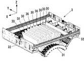
図1は本発明の一実施形態に係る記録システム(記録装置)1を概略的に示した正面図である。記録システム1は、転写体2を介して記録媒体Pにインク像を転写することで記録物P’を製造する、枚葉式のインクジェットプリンタである。記録システム1は、記録装置1Aと、搬送装置1Bとを含む。本実施形態では、X方向、Y方向、Z方向が、それぞれ、記録システム1の幅方向(全長方向)、奥行き方向、高さ方向を示している。記録媒体PはX方向に搬送される。<Recording system>
FIG. 1 is a front view schematically showing a recording system (recording apparatus) 1 according to an embodiment of the present invention. The
なお、「記録」には、文字、図形等有意の情報を形成する場合のみならず、有意無意を問わず、広く記録媒体上に画像、模様、パターン等を形成する、又は媒体の加工を行う場合も含まれ、人間が視覚で知覚し得るように顕在化したものであるか否かを問わない。また、本実施形態では「記録媒体」としてシート状の紙を想定するが、布、プラスチック・フィルム等であってもよい。 In "recording", not only when significant information such as characters and figures is formed, but also images, patterns, patterns, etc. are widely formed on a recording medium, or the medium is processed, regardless of whether it is significant or unintentional. Cases are also included, and it does not matter whether or not it is manifested so that it can be visually perceived by humans. Further, in the present embodiment, a sheet-shaped paper is assumed as the "recording medium", but a cloth, a plastic film, or the like may be used.
インクの成分については、特に限定はないが、本実施形態では、色材である顔料、水、樹脂を含む水性顔料インクを用いる場合を想定する。 The components of the ink are not particularly limited, but in the present embodiment, it is assumed that a water-based pigment ink containing a pigment, water, and a resin as coloring materials is used.
<記録装置>
記録装置1Aは、記録ユニット3、転写ユニット4および周辺ユニット5A〜5D、および、供給ユニット6を含む。<Recording device>
The
<記録ユニット>
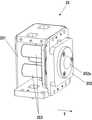
記録ユニット3は、複数の記録ヘッド30と、キャリッジ31とを含む。図1と図2を参照する。図2は記録ユニット3の斜視図である。記録ヘッド30は、転写体2に液体インクを吐出し、転写体2上に記録画像のインク像を形成する。<Recording unit>
The
本実施形態の場合、各記録ヘッド30は、Y方向に延設されたフルラインヘッドであり、使用可能な最大サイズの記録媒体の画像記録領域の幅分をカバーする範囲にノズルが配列されている。記録ヘッド30は、その下面に、ノズルが開口したインク吐出面を有しており、インク吐出面は、微小隙間(例えば数mm)を介して転写体2の表面と対向している。本実施形態の場合、転写体2は円軌道上を循環的に移動する構成であるため、複数の記録ヘッド30は、放射状に配置されている。 In the case of the present embodiment, each
各ノズルには吐出素子が設けられている。吐出素子は、例えば、ノズル内に圧力を発生させてノズル内のインクを吐出させる素子であり、公知のインクジェットプリンタのインクジェットヘッドの技術が適用可能である。吐出素子としては、例えば電気−熱変換体によりインクに膜沸騰を生じさせ気泡を形成することでインクを吐出する素子、電気−機械変換体によってインクを吐出する素子、静電気を利用してインクを吐出する素子等が挙げられる。高速で高密度の記録の観点からは電気−熱変換体を利用した吐出素子を用いることができる。 Each nozzle is provided with a discharge element. The ejection element is, for example, an element that generates pressure in the nozzle to eject the ink in the nozzle, and a technique of an inkjet head of a known inkjet printer can be applied. As the ejection element, for example, an element that ejects ink by causing film boiling in the ink by an electric-heat converter to form bubbles, an element that ejects ink by an electric-mechanical converter, and an element that uses static electricity to eject ink. Examples include a discharge element. From the viewpoint of high-speed and high-density recording, a discharge element using an electric-heat converter can be used.
本実施形態の場合、記録ヘッド30は、9つ設けられている。各記録ヘッド30は、互いに異なる種類のインクを吐出する。異なる種類のインクとは、例えば、色材が異なるインクであり、イエローインク、マゼンタインク、シアンインク、ブラックインク等のインクである。1つの記録ヘッド30は1種類のインクを吐出するが、1つの記録ヘッド30が複数種類のインクを吐出する構成であってもよい。このように複数の記録ヘッド30を設けた場合、そのうちの一部が色材を含まないインク(例えばクリアインク)を吐出してもよい。 In the case of this embodiment, nine recording heads 30 are provided. Each
キャリッジ31は、複数の記録ヘッド30を支持する。各記録ヘッド30は、インク吐出面側の端部がキャリッジ31に固定されている。これにより、インク吐出面と転写体2との表面の隙間をより精密に維持することができる。キャリッジ31は、案内ユニットRLの案内によって、記録ヘッド30を搭載しつつ変位可能に構成されている。本実施形態の場合、案内ユニットRLは、Y方向に延設されたレール状の構造であり、X方向に離間して一対設けられている。キャリッジ31のX方向の各側部にはスライド部32が設けられている。スライド部32は案内ユニットRLと係合し、案内ユニットRLの案内によってY方向にスライドする。 The
図3は記録ユニット3の変位態様を示しており、記録システム1の右側面を模式的に示した図である。記録システム1の後部には回復ユニット12が設けられている。回復ユニット12は記録ヘッド30の吐出性能を回復する機構を有する。そのような機構としては、例えば、記録ヘッド30のインク吐出面をキャッピングするキャップ機構、インク吐出面をワイピングするワイパ機構、インク吐出面から記録ヘッド30内のインクを負圧吸引する吸引機構を挙げることができる。 FIG. 3 shows the displacement mode of the
案内ユニットRLは、転写体2の側方から回復ユニット12に渡って延設されている。記録ユニット3は、案内ユニットRLの案内により、実線で記録ユニット3を示した吐出位置POS1と、破線で記録ユニット3を示した回復位置POS3との間で変位可能であり、不図示の駆動機構により移動される。 The guide unit RL extends from the side of the
吐出位置POS1は、記録ユニット3が転写体2にインクを吐出する位置であり、記録ヘッド30のインク吐出面が転写体2の表面に対向する位置である。回復位置POS3は、吐出位置POS1から退避した位置であり、記録ユニット3が回復ユニット12上に位置する位置である。回復ユニット12は記録ユニット3が回復位置POS3に位置した場合に、記録ヘッド30に対する性能回復処理を実行可能である。本実施形態の場合、記録ユニット3が回復位置POS3に到達する前の移動途中においても回復処理を実行可能である。吐出位置POS1と回復位置POS3の間には予備回復位置POS2がある。回復ユニット12は記録ヘッド30が吐出位置POS1から回復位置POS3へ移動している間に、予備回復位置POS2において記録ヘッド30に対する予備的な回復処理を実行可能である。 The
<転写ユニット>
図1を参照して転写ユニット4について説明する。転写ユニット4は、転写ドラム(転写胴)41と圧胴42とを含む。これらの胴は、Y方向の回転軸周りに回転する回転体であり、円筒形状の外周面を有している。図1において、転写ドラム41および圧胴42の各図形内に示した矢印は、これらの回転方向を示しており、転写ドラム41は時計回りに、圧胴42は反時計回りに回転する。<Transfer unit>
The
転写ドラム41は、その外周面に転写体2を支持する支持体である。転写体2は、転写ドラム41の外周面上に、周方向に連続的にあるいは間欠的に設けられる。連続的に設けられる場合、転写体2は無端の帯状に形成される。間欠的に設けられる場合、転写体2は、有端の帯状に複数のセグメントに分けて形成され、各セグメントは転写ドラム41の外周面に等ピッチで円弧状に配置することができる。 The
転写ドラム41の回転により、転写体2は円軌道上を循環的に移動する。転写ドラム41の回転位相により、転写体2の位置は、吐出前処理領域R1、吐出領域R2、吐出後処理領域R3およびR4、転写領域R5、転写後処理領域R6に区別することができる。転写体2はこれらの領域を循環的に通過する。 Due to the rotation of the
吐出前処理領域R1は、記録ユニット3によるインクの吐出前に転写体2に対する前処理を行う領域であり、周辺ユニット5Aによる処理が行われる領域である。本実施形態の場合、反応液が付与される。吐出領域R2は記録ユニット3が転写体2にインクを吐出してインク像を形成する形成領域である。吐出後処理領域R3およびR4はインクの吐出後にインク像に対する処理を行う処理領域であり、吐出後処理領域R3は周辺ユニット5Bによる処理が行われる領域であり、吐出後処理領域R4は周辺ユニット5Cによる処理が行われる領域である。転写領域R5は転写ユニット4により転写体上のインク像が記録媒体Pに転写される領域である。転写後処理領域R6は、転写後に転写体2に対する後処理を行う領域であり、周辺ユニット5Dによる処理が行われる領域である。 The ejection pre-processing region R1 is an region in which the
本実施形態の場合、吐出領域R2は、一定の区間を有する領域である。他の領域R1、R3〜R6は、吐出領域R2に比べるとその区間は狭い。時計の文字盤に喩えると、本実施形態の場合、吐出前処理領域R1は概ね10時の位置であり、吐出領域R2は概ね11時から1時の範囲であり、吐出後処理領域R3は概ね2時の位置であり、吐出後処理領域R4は概ね4時の位置である。転写領域R5は概ね6時の位置であり、転写後処理領域R6は概ね8時の領域である。 In the case of the present embodiment, the discharge region R2 is a region having a certain section. The sections of the other regions R1 and R3 to R6 are narrower than those of the discharge region R2. In the case of the present embodiment, the discharge pre-processing area R1 is approximately 10 o'clock, the discharge area R2 is approximately 11 o'clock to 1 o'clock, and the discharge post-processing area R3 is approximately 10 o'clock. It is the position at 2 o'clock, and the discharge post-processing area R4 is the position at about 4 o'clock. The transfer region R5 is at approximately 6 o'clock, and the post-transcriptional treatment region R6 is approximately 8 o'clock.
転写体2は、単層から構成してもよいが、複数層の積層体としてもよい。複数層で構成する場合、例えば、表面層、弾性層、圧縮層の三層を含んでもよい。表面層はインク像が形成される画像形成面を有する最外層である。圧縮層を設けることで、圧縮層が変形を吸収し、局所的な圧力変動に対してその変動を分散し、高速記録時においても転写性を維持することができる。弾性層は表面層と圧縮層との間の層である。 The
表面層の材料としては、樹脂、セラミック等各種材料を適宜用いることができるが、耐久性等の点で圧縮弾性率の高い材料を用いることができる。具体的には、アクリル樹脂、アクリルシリコーン樹脂、フッ素含有樹脂、加水分解性有機ケイ素化合物を縮合して得られる縮合物等が挙げられる。表面層には、反応液の濡れ性、画像の転写性等を向上させるために、表面処理を施して用いてもよい。表面処理としては、フレーム処理、コロナ処理、プラズマ処理、研磨処理、粗化処理、活性エネルギー線照射処理、オゾン処理、界面活性剤処理、シランカップリング処理などが挙げられる。これらを複数組み合わせてもよい。また、表面層に任意の表面形状を設けることもできる。 As the material of the surface layer, various materials such as resin and ceramic can be appropriately used, but a material having a high compressive elastic modulus can be used in terms of durability and the like. Specific examples thereof include an acrylic resin, an acrylic silicone resin, a fluorine-containing resin, and a condensate obtained by condensing a hydrolyzable organosilicon compound. The surface layer may be subjected to surface treatment in order to improve the wettability of the reaction solution, the transferability of the image, and the like. Examples of the surface treatment include frame treatment, corona treatment, plasma treatment, polishing treatment, roughening treatment, active energy ray irradiation treatment, ozone treatment, surfactant treatment, silane coupling treatment and the like. A plurality of these may be combined. Further, any surface shape can be provided on the surface layer.
圧縮層の材料としては、例えばアクリロニトリル−ブタジエンゴム、アクリルゴム、クロロプレンゴム、ウレタンゴム、シリコーンゴム等が挙げられる。このようなゴム材料の成形時には、所定量の加硫剤、加硫促進剤等を配合し、さらに発泡剤、中空微粒子或いは食塩等の充填剤を必要に応じて配合し、多孔質のゴム材料としてもよい。これにより、様々な圧力変動に対して気泡部分が体積変化を伴って圧縮されるため、圧縮方向以外への変形が小さく、より安定した転写性、耐久性を得ることができる。多孔質のゴム材料としては、各気孔が互いに連続した連続気孔構造のものと、各気孔がそれぞれ独立した独立気孔構造のものがあるが、いずれの構造であってもよく、これらの構造を併用してもよい。 Examples of the material of the compression layer include acrylonitrile-butadiene rubber, acrylic rubber, chloroprene rubber, urethane rubber, silicone rubber and the like. At the time of molding such a rubber material, a predetermined amount of a vulcanizing agent, a vulcanization accelerator, etc. are blended, and further, a filler such as a foaming agent, hollow fine particles, or sulfur is blended as necessary, and the porous rubber material is blended. May be. As a result, since the bubble portion is compressed with a volume change due to various pressure fluctuations, deformation in directions other than the compression direction is small, and more stable transferability and durability can be obtained. Porous rubber materials include those having a continuous pore structure in which each pore is continuous with each other and those having an independent pore structure in which each pore is independent, but any structure may be used, and these structures may be used in combination. You may.
弾性層の部材としては、樹脂、セラミック等、各種材料を適宜用いることができる。加工特性等の点で、各種エラストマー材料、ゴム材料を用いることができる。具体的には、例えばフルオロシリコーンゴム、フェニルシリコーンゴム、フッ素ゴム、クロロプレンゴム、ウレタンゴム、ニトリルゴム等が挙げられる。また、エチレンプロピレンゴム、天然ゴム、スチレンゴム、イソプレンゴム、ブタジエンゴム、エチレン/プロピレン/ブタジエンのコポリマー、ニトリルブタジエンゴム等が挙げられる。特に、シリコーンゴム、フルオロシリコーンゴム、フェニルシリコーンゴムは、圧縮永久ひずみが小さいため、寸法安定性、耐久性の面で有利である。また、温度による弾性率の変化が小さく、転写性の点でも有利である。 As the member of the elastic layer, various materials such as resin and ceramic can be appropriately used. Various elastomer materials and rubber materials can be used in terms of processing characteristics and the like. Specific examples thereof include fluorosilicone rubber, phenylsilicone rubber, fluororubber, chloroprene rubber, urethane rubber, nitrile rubber and the like. Further, ethylene propylene rubber, natural rubber, styrene rubber, isoprene rubber, butadiene rubber, ethylene / propylene / butadiene copolymer, nitrile butadiene rubber and the like can be mentioned. In particular, silicone rubber, fluorosilicone rubber, and phenylsilicone rubber are advantageous in terms of dimensional stability and durability because they have a small compression set. In addition, the change in elastic modulus with temperature is small, which is advantageous in terms of transferability.
表面層と弾性層の間、弾性層と圧縮層の間には、これらを固定するために各種接着剤や両面テープを用いることもできる。また、転写体2は、転写ドラム41に装着する際の横伸びの抑制や、コシを保つために圧縮弾性率が高い補強層を含んでもよい。また、織布を補強層としてもよい。転写体2は前記材質による各層を任意に組み合わせて作製することができる。 Various adhesives or double-sided tape can also be used between the surface layer and the elastic layer, and between the elastic layer and the compression layer to fix them. Further, the
圧胴42は、その外周面が転写体2に圧接される。圧胴42の外周面には、記録媒体Pの先端部を保持するグリップ機構が少なくとも一つ設けられている。グリップ機構は圧胴42の周方向に離間して複数設けてもよい。記録媒体Pは圧胴42の外周面に密接して搬送されつつ、圧胴42と転写体2とのニップ部を通過するときに、転写体2上のインク像が転写される。 The outer peripheral surface of the
転写ドラム41と圧胴42とを駆動するモータ等の駆動源は、これらに共通とし、歯車機構等の伝達機構により、駆動力を分配することができる。 A drive source such as a motor for driving the
<周辺ユニット>
周辺ユニット5A〜5Dは転写ドラム412の周囲に配置されている。本実施形態の場合、周辺ユニット5A〜5Dは、順に、付与ユニット、吸収ユニット、加熱ユニット、清掃ユニットである。<Peripheral unit>
付与ユニット5Aは、記録ユニット3によるインクの吐出前に、転写体2上に反応液を付与する機構である。反応液は、インクを高粘度化する成分を含有する液体である。ここで、インクの高粘度化とは、インクを構成している色材や樹脂等がインクを高粘度化する成分と接触することによって化学的に反応し、あるいは物理的に吸着し、これによってインクの粘度の上昇が認められることである。このインクの高粘度化には、インク全体の粘度上昇が認められる場合のみならず、色材や樹脂等のインクを構成する成分の一部が凝集することにより局所的に粘度の上昇が生じる場合も含まれる。 The applying
インクを高粘度化する成分は、金属イオン、高分子凝集剤など、特に制限はないが、インクのpH変化を引き起こして、インク中の色材を凝集させる物質を用いることができ、有機酸を用いることができる。反応液の付与機構としては、例えば、ローラ、記録ヘッド、ダイコーティング装置(ダイコータ)、ブレードコーティング装置(ブレードコータ)などが挙げられる。転写体2に対するインクの吐出前に反応液を転写体2に付与しておくと、転写体2に達したインクを直ちに定着させることができる。これにより、隣接するインク同士が混ざり合うブリーディングを抑制することができる。 The component that increases the viscosity of the ink is not particularly limited, such as a metal ion or a polymer flocculant, but a substance that causes a change in the pH of the ink and aggregates the coloring material in the ink can be used, and an organic acid can be used. Can be used. Examples of the reaction liquid application mechanism include rollers, recording heads, die coating devices (die coaters), blade coating devices (blade coaters), and the like. If the reaction solution is applied to the
吸収ユニット5Bは、転写前に、転写体2上のインク像から液体成分を吸収する機構である。インク像の液体成分を減少させることで、記録媒体Pに記録される画像のにじみ等を抑制することができる。液体成分の減少を異なる視点で説明すれば、転写体2上のインク像を構成するインクを濃縮すると表現することもできる。インクを濃縮するとは、インクに含まれる液体成分が減少することによって、インクに含まれる色材や樹脂といった固形分の液体成分に対する含有割合が増加することを意味する。 The
吸収ユニット5Bは、例えば、インク像に接触してインク像の液体成分の量を減少させる液吸収部材を含む。液吸収部材はローラの外周面に形成されてもよいし、液吸収部材が無端のシート状に形成され、循環的に走行されるものでもよい。インク像の保護の点で、液吸収部材の移動速度を転写体2の周速度と同じにして液吸収部材を転写体2と同期して移動させてもよい。 The
液吸収部材は、インク像に接触する多孔質体を含んでもよい。液吸収部材へのインク固形分付着を抑制するため、インク像に接触する面の多孔質体の孔径は、10μm以下であってもよい。ここで、孔径とは平均直径のことを示し、公知の手段、例えば水銀圧入法や、窒素吸着法、SEM画像観察等で測定可能である。なお、液体成分は、一定の形を有さず、流動性があり、ほぼ一定の体積を有するものであれば、特に限定されるものではない。例えば、インクや反応液に含まれる水や有機溶媒等が液体成分として挙げられる 。 The liquid absorbing member may include a porous body that comes into contact with the ink image. In order to suppress the adhesion of ink solids to the liquid absorbing member, the pore size of the porous body on the surface in contact with the ink image may be 10 μm or less. Here, the pore diameter indicates an average diameter, and can be measured by a known means such as a mercury intrusion method, a nitrogen adsorption method, SEM image observation, or the like. The liquid component is not particularly limited as long as it does not have a certain shape, has fluidity, and has a substantially constant volume. For example, water, organic solvent, etc. contained in ink or reaction liquid can be mentioned as liquid components.
加熱ユニット5Cは、転写前に、転写体2上のインク像を加熱する機構である。インク像を加熱することで、インク像中の樹脂が溶融し、記録媒体Pへの転写性を向上する。加熱温度は、樹脂の最低造膜温度(MFT)以上とすることができる。MFTは一般的に知られている手法、例えばJIS K 6828−2:2003や、ISO2115:1996に準拠した各装置で測定することが可能である。転写性及び画像の堅牢性の観点から、MFTよりも10℃以上高い温度で加熱してもよく、更に、20℃以上高い温度で加熱してもよい。加熱ユニット5Cは、例えば、赤外線等の各種ランプ、温風ファン等、公知の加熱デバイスを用いることができる。加熱効率の点で、赤外線ヒータを用いることができる。 The
清掃ユニット5Dは、転写後に転写体2上を清掃する機構である。清掃ユニット5Dは、転写体2上に残留したインクや、転写体2上のごみ等を除去する。清掃ユニット5Dは、例えば、多孔質部材を転写体2に接触させる方式、ブラシで転写体2の表面を擦る方式、ブレードで転写体2の表面をかきとる方式等の公知の方式を適宜用いることができる。また、清掃に用いる清掃部材は、ローラ形状、ウェブ形状等、公知の形状を用いることができる。 The
以上の通り、本実施形態では、付与ユニット5A、吸収ユニット5B、加熱ユニット5C、清掃ユニット5Dを周辺ユニットとして備えるが、これらの一部のユニットに転写体2の冷却機能を付与するか、あるいは、冷却ユニットを追加してもよい。本実施形態では、加熱ユニット5Cの熱により転写体2の温度が上昇する場合がある。記録ユニット3により転写体2にインクを吐出した後、インク像がインクの主溶剤である水の沸点を超えると、吸収ユニット5Bによる液体成分の吸収性能が低下する場合がある。吐出されたインクが水の沸点未満に維持されるように転写体2を冷却することで、液体成分の吸収性能を維持することができる。 As described above, in the present embodiment, the imparting
冷却ユニットは、転写体2に送風する送風機構や、転写体2に部材(例えばローラ)を接触させ、この部材を空冷または水冷で冷却する機構であってもよい。また、清掃ユニット5Dの清掃部材を冷却する機構であってもよい。冷却タイミングは、転写後、反応液の付与前までの期間であってもよい。 The cooling unit may be a blowing mechanism that blows air to the
<供給ユニット>
供給ユニット6は、記録ユニット3の各記録ヘッド30にインクを供給する機構である。供給ユニット6は記録システム1の後部側に設けられていてもよい。供給ユニット6は、インクの種類毎に、インクを貯留する貯留部TKを備える。貯留部TKは、メインタンクとサブタンクとによって構成されてもよい。各貯留部TKと各記録ヘッド30とは流路6aで連通し、貯留部TKから記録ヘッド30へインクが供給される。流路6aは、貯留部TKと記録ヘッド30との間でインクを循環させる流路であってもよく、供給ユニット6はインクを循環させるポンプ等を備えてもよい。流路6aの途中または貯留部TKには、インク中の気泡を脱気する脱気機構を設けてもよい。流路6aの途中または貯留部TKには、インクの液圧と大気圧との調整を行うバルブを設けてもよい。貯留部TK内のインク液面が、記録ヘッド30のインク吐出面よりも低い位置となるように、貯留部TKと記録ヘッド30のZ方向の高さが設計されてもよい。<Supply unit>
The supply unit 6 is a mechanism for supplying ink to each
<搬送装置>
搬送装置1Bは、記録媒体Pを転写ユニット4へ給送し、インク像が転写された記録物P’を転写ユニット4から排出する装置である。搬送装置1Bは、給送ユニット7、複数の搬送胴8、8a、二つのスプロケット8b、チェーン8cおよび回収ユニット8dを含む。図1において、搬送装置1Bの各構成の図形の内側の矢印はその構成の回転方向を示し、外側の矢印は記録媒体Pまたは記録物P’の搬送経路を示している。記録媒体Pは給送ユニット7から転写ユニット4へ搬送され、記録物P’は転写ユニット4から回収ユニット8dへ搬送される。給送ユニット7側を搬送方向で上流側と呼び、回収ユニット8d側を下流側と呼ぶ場合がある。<Transport device>
The
給送ユニット7は、複数の記録媒体Pが積載される積載部を含むと共に、積載部から一枚ずつ記録媒体Pを、最上流の搬送胴8に給送する給送機構を含む。各搬送胴8、8aはY方向の回転軸周りに回転する回転体であり、円筒形状の外周面を有している。各搬送胴8、8aの外周面には、記録媒体P(または記録物P’)の先端部を保持するグリップ機構が少なくとも一つ設けられている。各グリップ機構は、隣接する搬送胴間で記録媒体Pを受け渡されるように、その把持動作および解除動作が制御される。 The
二つの搬送胴8aは、記録媒体Pの反転用の搬送胴である。記録媒体Pを両面記録する場合、表面への転写後に、圧胴42から下流側に隣接する搬送胴8へ記録媒体Pを渡さずに、搬送胴8aに渡す。記録媒体Pは、二つの搬送胴8aを経由して表裏が反転され、圧胴42の上流側の搬送胴8を経由して再び圧胴42へ渡される。これにより、記録媒体Pの裏面が転写ドラム41に面することになり、裏面にインク像が転写される。 The two
チェーン8cは、二つのスプロケット8b間に巻き回されている。二つのスプロケット8bの一方は駆動スプロケットであり他方は従動スプロケットである。駆動スプロケットの回転によりチェーン8cが循環的に走行する。チェーン8cには、その長手方向に離間して複数のグリップ機構が設けられている。グリップ機構は、記録物P’の端部を把持する。下流端に位置する搬送胴8からチェーン8cのグリップ機構に記録物P’が渡され、グリップ機構に把持された記録物P’はチェーン8cの走行により回収ユニット8dへ搬送され、把持が解除される。これにより記録物P’が回収ユニット8d内に積載される。 The
<後処理ユニット>
搬送装置1Bには、後処理ユニット10A、10Bが設けられている。後処理ユニット10A、10Bは転写ユニット4よりも下流側に配置され、記録物P’に対して後処理を行う機構である。後処理ユニット10Aは、記録物P’の表面に対する処理を行い、後処理ユニット10Bは、記録物P’の裏面に対する処理を行う。処理の内容としては、例えば、記録物P’の画像記録面に、画像の保護や艶出し等を目的としたコーティングを挙げることができる。コーティングの内容としては、例えば、液体の塗布、シートの溶着、ラミネート等を挙げることができる。<Post-processing unit>
The
<検査ユニット>
搬送装置1Bには、検査ユニット9A、9Bが設けられている。検査ユニット9A、9Bは転写ユニット4よりも下流側に配置され、記録物P’の検査を行う機構である。<Inspection unit>
The
本実施形態の場合、検査ユニット9Aは、記録物P’に記録された画像を撮影する撮影装置であり、例えば、CCDセンサやCMOSセンサ等の撮像素子を含む。検査ユニット9Aは、連続的に行われる記録動作中に、記録画像を撮影する。検査ユニット9Aが撮影した画像に基づいて、記録画像の色味などの経時変化を確認し、画像データあるいは記録データの補正の可否を判断することができる。本実施形態の場合、検査ユニット9Aは、圧胴42の外周面に撮像範囲が設定されており、転写直後の記録画像を部分的に撮影可能に配置されている。検査ユニット9Aにより全ての記録画像の検査を行ってもよいし、所定数毎に検査を行ってもよい。 In the case of the present embodiment, the
本実施形態の場合、検査ユニット9Bも、記録物P’に記録された画像を撮影する撮影装置であり、例えば、CCDセンサやCMOSセンサ等の撮像素子を含む。検査ユニット9Bは、テスト記録動作において記録画像を撮影する。検査ユニット9Bは、記録画像の全体を撮影し、検査ユニット9Bが撮影した画像に基づいて、記録データに関する各種の補正の基本設定を行うことができる。本実施形態の場合、チェーン8cで搬送される記録物P’を撮影する位置に配置されている。検査ユニット9Bにより記録画像を撮影する場合、チェーン8cの走行を一時的に停止して、その全体を撮影する。検査ユニット9Bは、記録物P’上を走査するスキャナであってもよい。 In the case of the present embodiment, the
<制御ユニット>
次に、記録システム1の制御ユニットについて説明する。図4および図5は記録システム1の制御ユニット13のブロック図である。制御ユニット13は、上位装置(DFE)HC2に通信可能に接続され、また、上位装置HC2はホスト装置HC1に通信可能に接続される。<Control unit>
Next, the control unit of the
ホスト装置HC1では、記録画像の元になる原稿データが生成、あるいは保存される。ここでの原稿データは、例えば、文書ファイルや画像ファイル等の電子ファイルの形式で生成される。この原稿データは、上位装置HC2へ送信され、上位装置HC2では、受信した原稿データを制御ユニット13で利用可能なデータ形式(例えば、RGBで画像を表現するRGBデータ)に変換する。変換後のデータは、画像データとして上位装置HC2から制御ユニット13へ送信され、制御ユニット13は受信した画像データに基づき、記録動作を開始する。 In the host device HC1, the original data that is the source of the recorded image is generated or stored. The manuscript data here is generated in the form of an electronic file such as a document file or an image file. This manuscript data is transmitted to the higher-level device HC2, and the higher-level device HC2 converts the received manuscript data into a data format (for example, RGB data expressing an image in RGB) that can be used by the
本実施形態の場合、制御ユニット13は、メインコントローラ13Aと、エンジンコントローラ13Bとに大別される。メインコントローラ13Aは、処理部131、記憶部132、操作部133、画像処理部134、通信I/F(インタフェース)135、バッファ136および通信I/F137を含む。 In the case of the present embodiment, the
処理部131は、CPU等のプロセッサであり、記憶部132に記憶されたプログラムを実行し、メインコントローラ13A全体の制御を行う。記憶部132は、RAM、ROM、ハードディスク、SSD等の記憶デバイスであり、CPU131が実行するプログラムや、データを格納し、また、CPU131にワークエリアを提供する。操作部133は、例えば、タッチパネル、キーボード、マウス等の入力デバイスであり、ユーザの指示を受け付ける。 The
画像処理部134は例えば画像処理プロセッサを有する電子回路である。バッファ136は、例えば、RAM、ハードディスクやSSDである。通信I/F135は上位装置HC2との通信を行い、通信I/F137はエンジンコントローラ13Bとの通信を行う。図4において破線矢印は、画像データの処理の流れを例示している。上位装置HC2から通信IF135を介して受信された画像データは、バッファ136に蓄積される。画像処理部134はバッファ136から画像データを読み出し、読み出した画像データに所定の画像処理を施して、再びバッファ136に格納する。バッファ136に格納された画像処理後の画像データは、プリントエンジンが用いる記録データとして、通信I/F137からエンジンコントローラ13Bへ送信される。 The
図5に示すように、エンジンコントローラ13Bは、制御部14、15A〜15Eを含み、記録システム1が備えるセンサ群およびアクチュエータ群16の検知結果の取得および駆動制御を行う。これらの各制御部は、CPU等のプロセッサ、RAMやROM等の記憶デバイス、外部デバイスとのインタフェースを含む。なお、制御部の区分けは一例であり、一部の制御を更に細分化した複数の制御部で実行してもよいし、逆に、複数の制御部を統合して、それらの制御内容を一つの制御部で行うように構成してもよい。 As shown in FIG. 5, the
エンジン制御部14は、エンジンコントローラ13Bの全体の制御を行う。記録制御部15Aは、メインコントローラ13Aから受信した記録データをラスタデータ等、記録ヘッド30の駆動に適したデータ形式に変換する。記録制御部15Aは、各記録ヘッド30の吐出制御を行う。 The
転写制御部15Bは、付与ユニット5Aの制御、吸収ユニット5Bの制御、加熱ユニット5Cの制御、および清掃ユニット5Dの制御を行う。 The
信頼性制御部15Cは、供給ユニット6の制御、回復ユニット12の制御、および記録ユニット3を吐出位置POS1と回復位置POS3との間で移動させる駆動機構の制御を行う。 The
搬送制御部15Dは、転写ユニット4の駆動制御や、搬送装置1Bの制御を行う。検査制御部15Eは、検査ユニット9Bの制御、および検査ユニット9Aの制御を行う。 The transfer control unit 15D controls the drive of the
センサ群およびアクチュエータ群16のうち、センサ群には、可動部の位置や速度を検知するセンサ、温度を検知するセンサ、撮像素子等が含まれる。アクチュエータ群にはモータ、電磁ソレノイド、電磁バルブ等が含まれる。 Among the sensor group and the
<動作例>
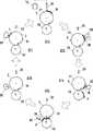
図6は記録動作の例を模式的に示す図である。転写ドラム41および圧胴42が回転されつつ、以下の各工程が循環的に行われる。状態ST1に示すように、始めに転写体2上に付与ユニット5Aから反応液Lが付与される。転写体2上の反応液Lが付与された部位は転写ドラム41の回転に伴って移動していく。反応液Lが付与された部位が記録ヘッド30の下に到達すると、状態ST2に示すように記録ヘッド30から転写体2にインクが吐出される。これによりインク像IMが形成される。その際、吐出されるインクが転写体2上の反応液Lと混ざりあうことで、色材の凝集が促進される。吐出されるインクは、供給ユニット6の貯留部TKから記録ヘッド30に供給される。<Operation example>
FIG. 6 is a diagram schematically showing an example of a recording operation. While the
転写体2上のインク像IMは転写体2の回転に伴って移動していく。インク像IMが吸収ユニット5Bに到達すると状態ST3に示すように吸収ユニット5Bによりインク像IMから液体成分が吸収される。インク像IMが加熱ユニット5Cに到達すると状態ST4に示すように加熱ユニット5Cによりインク像IMが加熱され、インク像IM中の樹脂が溶融し、インク像IMが造膜される。このようなインク像IMの形成に同期して、搬送装置1Bにより記録媒体Pが搬送される。 The ink image IM on the
状態ST5に示すように、インク像IMと記録媒体Pとが転写体2と圧胴42とのニップ部に到達し、記録媒体Pにインク像IMが転写され、記録物P’が製造される。ニップ部を通過すると、記録物P’に記録された画像が検査ユニット9Aにより撮影され、記録画像が検査される。記録物P’は搬送装置1Bにより回収ユニット8dへ搬送される。 As shown in the state ST5, the ink image IM and the recording medium P reach the nip portion between the
転写体2上のインク像IMが形成されていた部分は、清掃ユニット5Dに到達すると状態ST6に示すように清掃ユニット5Dにより清掃される。清掃後、転写体2は一回転したことになり、同様の手順で記録媒体Pへのインク像の転写が繰り返し行われる。上記の説明では理解を容易にするために、転写体2の一回転で一枚の記録媒体Pへのインク像IMの転写が一回行われるように説明したが、転写体2の一回転で複数枚の記録媒体Pへのインク像IMの転写が連続的に行うことができる。 When the portion of the
このような記録動作を継続していくと、各記録ヘッド30のメンテナンスが必要となる。図7は各記録ヘッド30のメンテナンスの際の動作例を示している。状態ST11は、吐出位置POS1に記録ユニット3が位置している状態を示す。状態ST12は、記録ユニット3が予備回復位置POS2を通過している状態を示し、通過中に回復ユニット12により記録ユニット3の各記録ヘッド30の吐出性能を回復する処理が実行される。その後、状態ST13に示すように、記録ユニット3が回復位置POS3に位置した状態で、回復ユニット12により各記録ヘッド30の吐出性能を回復する処理が実行される。 If such a recording operation is continued, maintenance of each
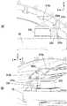
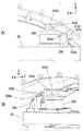
<記録ユニットの周辺構造>
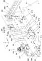
記録ユニット3の周辺構造の具体例について図8および図9を参照して説明する。図8および図9は記録ユニット3、転写ドラム41および回復ユニット12レイアウトを示している。図8は記録ユニット3が上述した吐出位置POS1に位置している状態を示し、図9は記録ユニット3が上述した回復位置POS3に位置している状態を示している。回復ユニット12は、転写ドラム41に対してY方向に隣接して配置されている。<Peripheral structure of recording unit>
A specific example of the peripheral structure of the
上述した案内ユニットRLに相当する案内ユニットRL1およびRL2は、いずれもY方向に平行に延設されており、かつ、互いにX方向に離間している。上述したスライド部32に相当するスライド部32A、32Bのうち、スライド部32Aは案内ユニットRL1に案内され、スライド部32Bは案内ユニットRL2に案内される。 The guide units RL1 and RL2 corresponding to the above-mentioned guide unit RL are both extended in parallel in the Y direction and are separated from each other in the X direction. Of the
本実施形態の場合、案内ユニットRL1は駆動機構DUを備える。駆動機構DUはモータ等の駆動源Mと、その駆動力をスライド部32Aに伝達する伝達機構BMとを含む。同図の例の場合、伝達機構BMはボールねじ機構であり、ボールねじ軸がY方向に延設されている。駆動源Mはボールねじ軸を回転させる。対応するスライド部32Aの底部には不図示のボールナットが設けられており、伝達機構BMのボールねじ軸と係合する。ボールねじ軸の回転によりスライド部32AがY方向にスライドする。 In the case of this embodiment, the guide unit RL1 includes a drive mechanism DU. The drive mechanism DU includes a drive source M such as a motor and a transmission mechanism BM that transmits the drive force to the
本実施形態の場合、案内ユニットRL2は駆動機構DUを備えておらず、レール部材を備えている。対応するスライド部32Bの底部にはこのレール部材と係合する不図示の係合部が設けられている。スライド部32Aとスライド部32Bは梁部材で連結されており、駆動機構DUによるスライド部32Aの移動に従動するようにしてスライド部32Bも移動する。これにより、記録ユニット3がY方向に平行移動する。 In the case of the present embodiment, the guide unit RL2 does not include the drive mechanism DU but includes a rail member. The bottom of the
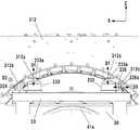
案内ユニットRL1およびRL2はその端部が一対のフレーム20に支持されている。フレーム20は、記録システム1の骨格の一部をなす固定構造体である。一対のフレーム20は外形がY字型の板状の部材であって、Y方向に互いに離間して配置されている。転写ドラム41は一対のフレーム20間に回転自在に支持されている。図8および図9に加えて図10(A)および図10(B)を参照する。図10(A)および図10(B)は転写ドラム41の軸支構造を示す模式図である。 The ends of the guide units RL1 and RL2 are supported by a pair of
転写ドラム41の回転中心軸41bはY方向に延設されており、その一方端部には歯車41aが固定されている。歯車41aには転写ドラム41と圧胴42とを駆動するモータ等の駆動源からの駆動力が伝達され、これにより転写ドラム41が回転する。回転中心軸41bの軸支構造には軸間調整機構21が設けられている。軸間調整機構21は、圧胴42の回転中心軸(不図示)に対して転写ドラム41の回転中心軸41bを変位させる機構である。これらの回転中心軸間の距離を調整すると転写ドラム41上の転写体2と圧胴42との圧接度合が変化する。これにより転写体2と圧胴42と間を通過する記録媒体の厚みに応じて、転写体表面と圧胴42との表面との圧接状態を調節することができ、記録媒体の厚みに対応した円滑な転写が実現できる。 The
軸間調整機構21はどのような構成であってもよいが、本実施形態の場合、偏芯軸受21aの回転による調整機構としている。偏芯軸受21aは円盤状の軸受であり、フレーム20の円形孔20aに回転自在に嵌合されている。偏芯軸受21aには、回転中心軸41bを回転自在に支持する軸受孔21bが形成されている。この軸受孔21bの中心(回転中心軸41の軸中心)C2は偏芯軸受21aの回転中心C1からずれた位置にある。したがって、偏芯軸受21aを回転させることにより、回転中心軸41bの中心C2の位置が変位する。これは圧胴42の回転中心軸(不図示)に対して転写ドラム41の回転中心軸41bが変位することを意味する。これにより、転写ドラム41と圧胴42の回転中心軸間の距離を調整することができる。図8および図9に示すハンドル21cは偏芯軸受21aに連結されており、ユーザはハンドル21cを操作することで偏芯軸受21aを回転し、軸間距離を調整することができる。ハンドル21cの位置は不図示のロック機構によりロックされる。 The
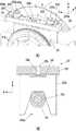
軸間調整機構21によって軸間距離を調整した結果、記録ユニット3に対して転写ドラム41が変位してしまうと、記録ヘッド30と転写体2との相対位置関係が変更される。これは転写体2に対するインクの吐出位置のずれの発生を招く場合がある。そこで本実施形態では記録ユニット3を転写ドラム41の回転中心軸41bと共に変位するように支持する構造を採用している。図8〜図10(B)に加えて図11(A)および図11(B)を参照する。図11(A)は転写ドラム41の歯車41a側の端部近傍を示す斜視図であり、図11(B)は支持ユニット23の構成例を示す図である。 If the
本実施形態の場合、吐出位置POS1において、記録ユニット3は支持ユニット23に支持される。支持ユニット23は回転中心軸41b上に支持されている。支持ユニット23は回転中心軸上に直接搭載する構成も採用可能であるが、回転中心軸41bの回転負荷とならないように、本実施形態の場合、回転中心軸41bに設けた筒部材22上に搭載されている。筒部材22は、本実施形態の場合、ボールベアリングであり、その内輪は回転中心軸41bが嵌合する中心孔を有しており、その外輪に支持ユニット23が搭載される。筒部材22はスリーブベアリングでもよく、また、外輪部分が角型形状の部材であってもよい。但し、本実施形態のように、筒部材22がボールベアリングであることにより、回転中心軸41bの円滑な回転を維持しつつ、支持ユニット23を介して記録ユニット3を支持することができる。 In the case of this embodiment, the
支持ユニット23は、フレーム20の中央部の上側に位置してX方向に延びる上部231と、フレーム20よりもY方向で転写ドラム41側に位置する搭載部232とを一体的に備えている。搭載部232の下部には台形状の切り欠き232aが形成されており、搭載部232の下部は二股に分岐した一対の脚部を形成している。切り欠き232aが筒部材22の外輪に三点で接触して搭載部232が鞍乗の態様で筒部材22上に搭載される。上部231の中央部には当接部材23aが装着される装着孔23bがZ方向に形成されている。当接部材23aは例えばボルト等のねじ軸であり、装着孔23bは例えばねじ孔である。 The
当接部材23aの下端はフレーム20に当接する。これにより、支持ユニット23が回転中心軸41b回りに回転してしまうことを阻止する。当接部材23aは支持ユニット23の回り止めである。 The lower end of the
軸間調整機構21によって軸間距離を調整する場合、当接部材23aは必要に応じて緩めてフレーム20から離間される。軸間調整機構21によって転写ドラム41を変位させると、回転中心軸41bと共に支持ユニット23も変位する。このため、記録ヘッド30と転写体2との相対位置関係が維持され、その位置調整が不要となる。したがって、転写体2に対するインクの吐出位置のずれの発生を低減することができる。軸間距離の調整が終了すると、当接部材23aの下端をフレーム20に当接させて回り止めとする。 When the distance between the shafts is adjusted by the shaft-to-
次に、本実施形態の場合、記録ユニット3は、吐出位置POS1と回復位置POS3との間で変位可能であり、支持ユニット23に対して着脱自在である。支持ユニット23は、回転中心軸41bと共に変位することから、支持ユニット23に装着する際に記録ユニット3が支持ユニット23に対して適切に装着される必要がある。本実施形態の場合、図11(A)に示すように、位置決め部材233〜235を含む位置決め構造を支持ユニット23に設けると共に、スライド部32Aおよび32Bに対して記録ユニット3を昇降ならびにフローティング支持する構成としている。その構造例について図12〜図14を参照して説明する。 Next, in the case of the present embodiment, the
図12はスライド部32Aの一部の斜視図、図13はスライド部32Aからキャリッジ31を取り外した斜視図である。ここではスライド部32Aの構成について説明するが、スライド部32Bも同様の構成である。 FIG. 12 is a perspective view of a part of the
スライド部32Aは、メインフレーム321とサブフレーム322とを備える。メインフレーム321はL字型の部材であり、Y方向に延設されている。サブフレーム322もL字型の部材であり、Y方向に延設されている。サブフレーム322はメインフレーム321の内側に配置され、複数のスライド機構323を介してメインフレーム321に連結されている。スライド機構323は、Z方向に延びるレール部材323aとレール部材323a上をスライドするスライダ323bとを備える。レール部材323aはメインフレーム321に固定され、スライダ323bはサブフレーム322の縦壁部322bにブラケットを介して固定されている。スライド機構323を設けたことで、サブフレーム322はメインフレーム321に対してZ方向に相対変位自在である。The
キャリッジ31は、そのX方向の端部311においてサブフレーム322に支持されている。メインフレーム321とサブフレーム322との間には昇降ユニット33が設けられている。昇降ユニット33はメインフレーム321に対してサブフレーム322を昇降する。換言すると、昇降ユニット33によって記録ユニット3がメインフレーム321に対して昇降される。昇降ユニット33はスライド部32Aだけでなくスライド部32Bにも設けられており、これらが同期的に駆動されることで記録ユニット3がZ方向に平行移動する。The
昇降ユニット33は、本実施形態の場合、駆動源331と、伝達機構332および333とを備える。駆動源331は本実施形態の場合、モータであり、メインフレーム321に固定されている。伝達機構333は本実施形態の場合、ボールねじ機構であり、ボールねじ軸333aとボールねじ軸333aと係合するボールナット333bとを備える。ボールねじ軸333aはメインフレーム321に回転自在に支持されており、その回転軸方向はZ方向である。ボールナット333bはサブフレーム322に支持されている。ボールねじ軸333aの回転によりボールナット333bが移動し、サブフレーム322が昇降する。In the case of this embodiment, the elevating
伝達機構332は本実施形態の場合、ベルト伝動機構であり、駆動源331の駆動力をボールねじ軸333aに伝達する。駆動源331の駆動制御によりサブフレーム322、つまり、記録ユニット3の昇降制御が可能である。 In the case of this embodiment, the
サブフレーム322とキャリッジ31との間のフローティング支持構造について説明する。本実施形態においてキャリッジ31は、その端部311がサブフレーム322の底壁322a上に載置されただけの支持態様となっており、キャリッジ31はX、Y、Zの各方向についてサブフレーム322に対して相対変位可能である。 The floating support structure between the
底壁322aには複数の載置部材322cが設けられており、端部311は複数の載置部材322c上に載置される。載置部材322cの頂部には、端部311を下から支える球面状の突起が形成されており、X方向およびY方向における端部311の変位の摩擦を小さくしている。 The
底壁322aには、また、複数の位置規制部材322dを備える。位置規制部材322dは、Z方向に延びる軸部材であり、端部311に形成された開口311bを通過する。開口311bの周縁と位置規制部材322dとが互いに当接することで記録ユニット3の相対変位が規制される。位置規制部材322dおよび開口311bは記録ユニット3の相対変位の範囲に対応した大きさに設計される。 The
サブフレーム322とキャリッジ31との間には付勢ユニット34および付勢ユニット35が設けられている。付勢ユニット34はキャリッジ31をX方向の一方向に付勢し、付勢ユニット35はキャリッジ31をY方向の一方向に付勢する。これらの付勢方向は、詳細を後述する位置決め部材234および235に対して、キャリッジ31を当接させる方向に設定されている。 An urging
付勢ユニット34は本実施形態の場合、弾性部材であり、特に、コイルばねである。付勢ユニット34の一端は縦壁322bに設けた係止部322fに係止され、他端は端部311に設けた係止部311aに係止されている。 In the case of this embodiment, the urging
付勢ユニット35は、その斜視図が図14に示されている。付勢ユニット35は、ケース351と、可動部352と、これらの間に装填された弾性部材(ここではコイルばね)353とを備える。可動部352はケース351に対してY方向に変位自在であり、その一部には球面形状の押圧部352aが設けられている。 A perspective view of the urging
図12、図13に戻り、付勢ユニット34は端部311上に搭載されている。サブフレーム322には、押圧部352aと当接する壁部322eが設けられている。壁部322eは端部311に形成した溝311cを通過して端部311上に突出している。弾性部材353の付勢により押圧部352aが壁部322eをY方向に押圧する。 Returning to FIGS. 12 and 13, the urging
以上の構成により、記録ユニット3はスライド部32Aおよび32Bにフローティング支持されている。 With the above configuration, the
次に、図15〜図20を参照して、吐出位置POS1における記録ユニット3の位置決め構造について説明する。図15は支持ユニット上に記録ユニット3が搭載され、その位置決めが行われた状態を示している。 Next, the positioning structure of the
支持ユニット23には、位置決め部材233〜235が設けられている。位置決め部材233は本実施形態の場合、X方向に離間して二つ設けられている。位置決め部材234および235はそれぞれ一つずつ設けられている。位置決め部材233は球面状の当接部312aを有している。位置決め部材234は平面状の当接部234aを有している(図15では位置決め部材234の裏側に位置して隠れている。)。X、Y、Zの方向で当接部234aの面を表すと当接部234aはX−Z平面である。位置決め部材235は平面状の当接部235aを有している。X、Y、Zの方向で当接部235aの面を表すと当接部235aはY−Z平面である。 The
キャリッジ31の側壁312には、当接部312a〜312cが形成されている。当接部312aは当接部233aと当接する。当接部312aは平面状に形成され、X、Y、Zの方向で当接部312aの面を表すと当接部233aはX−Y平面である。当接部233aと当接部312aの当接方向D1は上下方向であり、これらの当接によって支持ユニット23に対するキャリッジ31の上下方向(Z方向)の位置決めがなされる。The
当接部312bは当接部234aと当接する。当接部312bは平面状に形成され、X、Y、Zの方向で当接部312bの面を表すと当接部312bはX−Z平面である。当接部234aと当接部312bの当接方向D2は奥行方向であり、これらの当接によって支持ユニット23に対するキャリッジ31の奥行方向(Y方向)の位置決めがなされる。The abutting
当接部312cは当接部235aと当接する。当接部312cは平面状に形成され、X、Y、Zの方向で当接部312cの面を表すと当接部312cはY−Z平面である。当接部235aと当接部312cの当接方向D3は左右方向であり、これらの当接によって支持ユニット23に対するキャリッジ31の左右方向(X方向)の位置決めがなされる。The
図16(A)〜図20(B)を参照して、記録ユニット3を回復位置POS3から記録位置POS1へ戻したときの、支持ユニット23に対する記録ユニット3の位置決め態様について説明する。 With reference to FIGS. 16A to 20B, the positioning mode of the
図16(A)および図16(B)は位置決め前の状態を示す。記録ユニット3は吐出位置POS1よりも回復位置POS3側に位置しており、また、上昇位置に位置している。当接部233a〜235aと、当接部312a〜312cとは離間している。 16 (A) and 16 (B) show the state before positioning. The
この後、案内ユニットRL1の駆動機構DUの駆動により、記録ユニット3が吐出位置POS1よりも僅かに回復位置POS3側の位置に到達すると、昇降ユニット33により記録ユニット3の降下を開始する。 After that, when the
図17(A)および図17(B)は記録ユニット3の降下途中の状態を示している。当接部233a、234aと、当接部312a、312bとは離間している。当接部312cの下方には傾斜面312c’が、当接部235aの上方には傾斜面235a’がそれぞれ形成されている。記録ユニット3は付勢ユニット34によってX方向の同図左側に付勢されており、記録ユニット3の降下途中で、これらの傾斜面が当接し始める。 17 (A) and 17 (B) show the state of the
図18(A)および図18(B)は記録ユニット3が更に降下した降下途中の状態を示している。当接部233a、234aと、当接部312a、312bとは離間している。各傾斜面235a’、312c’の案内によって、記録ユニット3は付勢ユニット34の付勢に抗してX方向の同図右側に変位し、当接部235aと当接部312cとがX方向に当接する。こうして初めに記録ユニット3のX方向の位置決めがなされる。 FIGS. 18 (A) and 18 (B) show a state in which the
図19(A)および図19(B)は記録ユニット3が更に降下した状態を示している。当接部234aと、当接部312bとは離間している。当接部233aと当接部312aとがZ方向に当接し、記録ユニット3のZ方向の位置決めがなされる。記録ユニット3は、サブフレーム322の載置部材322cから位置決め部材233上へ移載された状態となる。 19 (A) and 19 (B) show a state in which the
図20(A)および図20(B)は記録ユニット3が吐出位置POS1に到達して停止し、その降下も完了状態を示している。記録ユニット3は付勢ユニット35によってY方向の同図手前側に付勢されており、記録ユニット3が吐出位置POS1に到達する過程で当接部234aと当接部312bとがY方向に当接し、記録ユニット3のY方向の位置決めがなされる。こうして本実施形態では、X方向、Z方向、Y方向の順番で、一方向ずつ支持ユニット23に対する記録ユニット3の位置決めが行われるので、三方向の位置決めをより確実に行うことができる。記録ユニット3を回復位置POS3へ移動する場合は昇降ユニット33の駆動により記録ユニット3を上昇させつつ、案内ユニットRL1の駆動機構DUの駆動によりY方向へ移動すればよい。これにより記録ユニット3が支持ユニット23から分離して回復ユニット12へ移動する。 20 (A) and 20 (B) show that the
以上の位置決め構造により、軸間調整機構21によって軸間距離が調整された結果、支持ユニット23が変位したとしても、支持ユニット23に対して記録ユニット3を的確に位置決めできる。なお、軸間調整機構21を備えておらず、支持ユニット23が変位しない構成においても、本実施形態のように記録ユニット3の位置が変位する構成においては、支持ユニット23に対する記録ユニット3の位置決めの点で、上述した位置決め構造は有利である。このような位置決め構造により、記録ヘッド30が回復位置POS3から吐出位置POS1へ戻った場合に、その位置精度を向上することができる。 With the above positioning structure, even if the
<他の実施形態>
上記実施形態では、記録ユニット3が複数の記録ヘッド30を有するが、一つの記録ヘッド30を有してもよい。記録ヘッド30はフルラインヘッドでなくてもよく、記録ヘッド30を着脱自在に搭載するキャリッジをY方向に移動させながら記録ヘッド30からインクを吐出してインク像を形成するシリアル方式であってもよい。<Other embodiments>
In the above embodiment, the
記録媒体Pの搬送機構は、ローラ対によって記録媒体Pを挟持して搬送する方式等、他の方式であってもよい。ローラ対によって記録媒体Pを搬送する方式等においては、記録媒体Pとしてロールシートを用いてもよく、転写後にロールシートをカットして記録物P’を製造してもよい。 The transport mechanism of the recording medium P may be another method such as a method of sandwiching and transporting the recording medium P by a pair of rollers. In a method of transporting the recording medium P by a pair of rollers or the like, a roll sheet may be used as the recording medium P, or the roll sheet may be cut after transfer to produce a recorded material P'.
また、本発明は上述の実施形態の1以上の機能を実現するプログラムをネットワーク又は記憶媒体を介してシステム又は装置に供給し、そのシステム又は装置のコンピュータにおける1つ以上のプロセッサがプログラムを読出し実行する処理でも実現可能である。また、1以上の機能を実現する回路(例えば、ASIC)によっても実現可能である。 The present invention also supplies a program that realizes one or more functions of the above-described embodiment to a system or device via a network or storage medium, and one or more processors in the computer of the system or device reads and executes the program. It can also be realized by the processing to be performed. It can also be realized by a circuit (for example, ASIC) that realizes one or more functions.
2 転写体、3 記録ユニット、12 回復ユニット、21 軸間調整機構、23 支持ユニット、41 転写ドラム、42 圧胴、RL1 案内ユニット、RL2 案内ユニット2 Transfer unit, 3 Recording unit, 12 Recovery unit, 21 Inter-axis adjustment mechanism, 23 Support unit, 41 Transfer drum, 42 Cushion cylinder, RL1 guide unit, RL2 guide unit
Claims (6)
Translated fromJapanese前記記録手段の性能を回復する回復手段と、
前記回復手段により前記記録手段の性能を回復するための回復位置と、前記記録手段により前記被吐出媒体にインクを吐出するための吐出位置との間で、前記記録手段の変位を案内する案内手段と、
前記吐出位置において前記記録手段を支持する支持手段と、
前記支持手段に対して前記記録手段を昇降する昇降手段と、
前記吐出位置において前記記録手段が前記支持手段上に降下されることにより、前記記録手段を位置決めする位置決め構造と、を備える記録装置であって、
前記昇降手段は、固定フレームに対して、昇降フレームを昇降し、
前記記録手段は、前記昇降フレームに対して、互いに交差する水平二方向および前記記録装置の高さ方向に沿った上下方向の各方向に相対変位可能に載置されている、
ことを特徴とする記録装置。Recordingmeans for ejecting inkonto adischarge receiving medium,
A recovery means that restores the performance of the recording means,
Guidance means for guiding the displacement of the recording means between the recovery position for recovering the performance of the recording means by the recovery means and the ejection position for ejecting ink to the ejected medium by the recording means. When,
A support means that supports the recording means at the discharge position,
An elevating means for raising and lowering the recording means with respect to the supporting means,
Whereinby said recording means in the discharge positionis lowered onto said support means,a recording apparatus and a positioning structure for positioning the recording means,
The elevating means raises and lowers the elevating frame with respect to the fixed frame.
The recording means is mounted so as to be relatively displaceable with respect to the elevating frame in two horizontal directions intersecting with each other and in each of the vertical directions along the height direction of the recording device .
A recording device characterized by that.
前記記録手段の性能を回復する回復手段と、
前記回復手段により前記記録手段の性能を回復するための回復位置と、前記記録手段により前記被吐出媒体にインクを吐出するための吐出位置との間で、前記記録手段の変位を案内する案内手段と、
前記吐出位置において前記記録手段を支持する支持手段と、
前記支持手段に対して前記記録手段を昇降する昇降手段と、
前記吐出位置において前記記録手段が前記支持手段上に降下されることにより、前記記録手段を位置決めする位置決め構造と、を備える記録装置であって、
前記記録手段は、
記録ヘッドと、
前記記録ヘッドを支持するキャリッジと、を備え、
前記位置決め構造は、
前記支持手段に設けられた複数の第一の当接部と、
前記キャリッジに設けられ、前記複数の第一の当接部と当接する複数の第二の当接部と、を含み、
前記複数の第一の当接部と前記複数の第二の当接部の組み合わせは、当接方向が互いに異なる複数の組み合わせを含み、
前記複数の組み合わせの一つは、当接方向が前記記録装置の高さ方向に沿った方向となる組み合わせであり、
前記複数の組み合わせの別の一つは、当接方向が前記吐出位置における前記被吐出媒体の移動方向に沿った方向となる組合せであり、
前記複数の組み合わせの更に別の一つは、当接方向が前記移動方向と交差し、前記吐出位置における前記被吐出媒体の幅方向となる組み合わせである、
ことを特徴とする記録装置。A recording means that ejects ink to themoving medium to be ejected,
A recovery means that restores the performance of the recording means,
Guidance means for guiding the displacement of the recording means between the recovery position for recovering the performance of the recording means by the recovery means and the ejection position for ejecting ink to the ejected medium by the recording means. When,
A support means that supports the recording means at the discharge position,
An elevating means for raising and lowering the recording means with respect to the supporting means,
Whereinby said recording means in the discharge positionis lowered onto said support means,a recording apparatus and a positioning structure for positioning the recording means,
The recording means is
With the recording head,
A carriage that supports the recording head is provided.
The positioning structure is
A plurality of first contact portions provided on the support means,
A plurality of second contact portions provided on the carriage and in contact with the plurality of first contact portions, and include a plurality of second contact portions.
The combination of the plurality of first contact portions and the plurality of second contact portions includes a plurality of combinations having different contact directions from each other.
One of the plurality of combinations is a combination in which the contact direction is along the height direction of the recording device.
Another one of the plurality of combinations is a combination in which the contact direction is a direction along the moving direction of the ejected medium at the ejection position.
Yet another one of the plurality of combinations is a combination in which the contact direction intersects the moving direction and becomes the width direction of the ejected medium at the ejection position .
A recording device characterized by that.
前記回復位置は、前記吐出位置に対して、前記水平二方向のうちの第一方向に離間した位置である、
ことを特徴とする記録装置。The recording device according to claim 1.
The recovery position is a position separated from the discharge position in the first of the two horizontal directions.
A recording device characterized by that .
前記被吐出媒体は、ドラムに支持され、
前記水平二方向のうちの第二方向は、前記ドラムの接線方向であり、前記第一方向は前記ドラムの回転軸方向である、
ことを特徴とする記録装置。The recording device according to claim 3.
The ejected medium is supported by a drum and is supported by a drum.
The second of the two horizontal directions is the tangential direction of the drum, and the first direction is the rotation axis direction of the drum.
A recording device characterized by that .
前記回復位置は、前記吐出位置に対して、前記吐出位置における前記被吐出媒体の前記幅方向に離間した位置である、
ことを特徴とする記録装置。The recording device according to claim 2.
The recovery position is a position separated from the discharge position in the width direction of the discharge medium at the discharge position.
A recording device characterized by that .
前記記録装置は、前記被吐出媒体としての転写体を介して記録媒体にインク像を転写する装置であり、
前記記録手段は、前記転写体にインクを吐出して前記転写体上にインク像を形成する、
ことを特徴とする記録装置。The recording device according to any one of claims 1 to 5.
The recording device is a device that transfers an ink image to a recording medium via a transfer body as the ejection medium.
The recording means ejects ink to the transfer body to form an ink image on the transfer body.
A recording device characterized by that .
Priority Applications (2)
| Application Number | Priority Date | Filing Date | Title |
|---|---|---|---|
| JP2017078481AJP6970521B2 (en) | 2017-04-11 | 2017-04-11 | Recording device |
| US15/937,949US10369780B2 (en) | 2017-04-11 | 2018-03-28 | Printing apparatus |
Applications Claiming Priority (1)
| Application Number | Priority Date | Filing Date | Title |
|---|---|---|---|
| JP2017078481AJP6970521B2 (en) | 2017-04-11 | 2017-04-11 | Recording device |
Publications (3)
| Publication Number | Publication Date |
|---|---|
| JP2018176528A JP2018176528A (en) | 2018-11-15 |
| JP2018176528A5 JP2018176528A5 (en) | 2020-05-14 |
| JP6970521B2true JP6970521B2 (en) | 2021-11-24 |
Family
ID=63710222
Family Applications (1)
| Application Number | Title | Priority Date | Filing Date |
|---|---|---|---|
| JP2017078481AExpired - Fee RelatedJP6970521B2 (en) | 2017-04-11 | 2017-04-11 | Recording device |
Country Status (2)
| Country | Link |
|---|---|
| US (1) | US10369780B2 (en) |
| JP (1) | JP6970521B2 (en) |
Family Cites Families (15)
| Publication number | Priority date | Publication date | Assignee | Title |
|---|---|---|---|---|
| US6682189B2 (en) | 2001-10-09 | 2004-01-27 | Nexpress Solutions Llc | Ink jet imaging via coagulation on an intermediate member |
| US6639527B2 (en)* | 2001-11-19 | 2003-10-28 | Hewlett-Packard Development Company, L.P. | Inkjet printing system with an intermediate transfer member between the print engine and print medium |
| US6764160B1 (en)* | 2002-12-16 | 2004-07-20 | Xerox Corporation | Printhead interposing maintenance apparatus and method and image producing machine having same |
| JP4810303B2 (en) | 2006-05-11 | 2011-11-09 | キヤノン株式会社 | Inkjet recording device |
| JP2008036944A (en)* | 2006-08-04 | 2008-02-21 | Olympus Corp | Image recorder |
| JP4858447B2 (en)* | 2008-01-10 | 2012-01-18 | 富士ゼロックス株式会社 | Droplet discharge device |
| JP4613978B2 (en)* | 2008-05-13 | 2011-01-19 | 富士ゼロックス株式会社 | Droplet discharge device |
| JP5441494B2 (en) | 2008-08-07 | 2014-03-12 | キヤノン株式会社 | Inkjet recording device |
| JP5416068B2 (en)* | 2010-09-28 | 2014-02-12 | 富士フイルム株式会社 | Inkjet recording device |
| JP2012161961A (en) | 2011-02-04 | 2012-08-30 | Olympus Corp | Inkjet printer |
| JP5917083B2 (en) | 2011-10-21 | 2016-05-11 | キヤノン株式会社 | Inkjet recording apparatus and maintenance method |
| JP5921136B2 (en) | 2011-10-21 | 2016-05-24 | キヤノン株式会社 | Ink jet recording apparatus and logistics ink discharge method |
| JP5955053B2 (en) | 2012-03-28 | 2016-07-20 | キヤノン株式会社 | Recording apparatus and recording apparatus control method |
| JP6321920B2 (en)* | 2012-05-02 | 2018-05-09 | 株式会社小森コーポレーション | Sheet digital printing machine |
| CN205272883U (en)* | 2016-01-13 | 2016-06-01 | 北京龙日艺通文化艺术有限公司 | Broad width UV ink jet printer |
- 2017
- 2017-04-11JPJP2017078481Apatent/JP6970521B2/ennot_activeExpired - Fee Related
- 2018
- 2018-03-28USUS15/937,949patent/US10369780B2/ennot_activeExpired - Fee Related
Also Published As
| Publication number | Publication date |
|---|---|
| US10369780B2 (en) | 2019-08-06 |
| JP2018176528A (en) | 2018-11-15 |
| US20180290444A1 (en) | 2018-10-11 |
Similar Documents
| Publication | Publication Date | Title |
|---|---|---|
| JP6781617B2 (en) | Liquid absorber, recording system, recording method and manufacturing method | |
| JP2019018388A (en) | Recording device | |
| JP2019018389A (en) | Recording device | |
| JP2018144358A (en) | Ink jet recording apparatus and recording method for the same | |
| JP2022100414A (en) | Ink jet recording apparatus and temperature control method | |
| JP6895775B2 (en) | Recording device and its adjustment method | |
| JP6948133B2 (en) | Liquid absorber, recording device, recording method and manufacturing method | |
| JP2018192678A (en) | Image processing apparatus, control method, and program | |
| JP6824075B2 (en) | Recording device | |
| JP2019142030A (en) | Inkjet recording device | |
| JP6960756B2 (en) | Liquid absorber, recording device, and recording method | |
| JP2018133742A (en) | Recording apparatus, inspection apparatus, and control method | |
| JP6937624B2 (en) | Inkjet recording device and its recording method | |
| JP6970521B2 (en) | Recording device | |
| JP7562313B2 (en) | Recording device, control method and program | |
| JP2020023105A (en) | Recording apparatus and control method thereof | |
| JP2019018415A (en) | Recording apparatus and recording control method therefor | |
| JP7090500B2 (en) | Inkjet recording device and its control method | |
| JP2018176527A (en) | Recording device | |
| JP6976091B2 (en) | Recording device and control method | |
| JP2021079660A (en) | Inkjet recording device and method for controlling temperature of the same | |
| JP6864521B2 (en) | Recording device and control method | |
| JP2020023113A (en) | Recording device and recording control method thereof | |
| JP7483559B2 (en) | Inkjet recording device | |
| JP7090501B2 (en) | Inkjet recording device and its control method |
Legal Events
| Date | Code | Title | Description |
|---|---|---|---|
| A521 | Request for written amendment filed | Free format text:JAPANESE INTERMEDIATE CODE: A523 Effective date:20200401 | |
| A621 | Written request for application examination | Free format text:JAPANESE INTERMEDIATE CODE: A621 Effective date:20200401 | |
| RD01 | Notification of change of attorney | Free format text:JAPANESE INTERMEDIATE CODE: A7421 Effective date:20210103 | |
| A521 | Request for written amendment filed | Free format text:JAPANESE INTERMEDIATE CODE: A523 Effective date:20210113 | |
| A977 | Report on retrieval | Free format text:JAPANESE INTERMEDIATE CODE: A971007 Effective date:20210205 | |
| A131 | Notification of reasons for refusal | Free format text:JAPANESE INTERMEDIATE CODE: A131 Effective date:20210308 | |
| A521 | Request for written amendment filed | Free format text:JAPANESE INTERMEDIATE CODE: A523 Effective date:20210421 | |
| TRDD | Decision of grant or rejection written | ||
| A01 | Written decision to grant a patent or to grant a registration (utility model) | Free format text:JAPANESE INTERMEDIATE CODE: A01 Effective date:20211001 | |
| A61 | First payment of annual fees (during grant procedure) | Free format text:JAPANESE INTERMEDIATE CODE: A61 Effective date:20211029 | |
| R151 | Written notification of patent or utility model registration | Ref document number:6970521 Country of ref document:JP Free format text:JAPANESE INTERMEDIATE CODE: R151 | |
| LAPS | Cancellation because of no payment of annual fees |