JP6968784B2 - How to determine the distance between the vehicle and the classifier - Google Patents
How to determine the distance between the vehicle and the classifierDownload PDFInfo
- Publication number
- JP6968784B2 JP6968784B2JP2018514307AJP2018514307AJP6968784B2JP 6968784 B2JP6968784 B2JP 6968784B2JP 2018514307 AJP2018514307 AJP 2018514307AJP 2018514307 AJP2018514307 AJP 2018514307AJP 6968784 B2JP6968784 B2JP 6968784B2
- Authority
- JP
- Japan
- Prior art keywords
- vehicle
- classifier
- image sequence
- column
- transmission
- Prior art date
- Legal status (The legal status is an assumption and is not a legal conclusion. Google has not performed a legal analysis and makes no representation as to the accuracy of the status listed.)
- Active
Links
- 230000005540biological transmissionEffects0.000claimsdescription23
- 238000000034methodMethods0.000claimsdescription17
- 238000005259measurementMethods0.000claimsdescription6
- 238000001228spectrumMethods0.000claimsdescription6
- 238000000691measurement methodMethods0.000claimsdescription4
- 230000001360synchronised effectEffects0.000claimsdescription4
- 230000001960triggered effectEffects0.000description2
- 101150064009PLLP geneProteins0.000description1
- 238000001514detection methodMethods0.000description1
- 238000010586diagramMethods0.000description1
- 238000005265energy consumptionMethods0.000description1
- 238000005516engineering processMethods0.000description1
- MYWUZJCMWCOHBA-VIFPVBQESA-NmethamphetamineChemical compoundCN[C@@H](C)CC1=CC=CC=C1MYWUZJCMWCOHBA-VIFPVBQESA-N0.000description1
- 230000003595spectral effectEffects0.000description1
Images


Classifications
- G—PHYSICS
- G01—MEASURING; TESTING
- G01S—RADIO DIRECTION-FINDING; RADIO NAVIGATION; DETERMINING DISTANCE OR VELOCITY BY USE OF RADIO WAVES; LOCATING OR PRESENCE-DETECTING BY USE OF THE REFLECTION OR RERADIATION OF RADIO WAVES; ANALOGOUS ARRANGEMENTS USING OTHER WAVES
- G01S13/00—Systems using the reflection or reradiation of radio waves, e.g. radar systems; Analogous systems using reflection or reradiation of waves whose nature or wavelength is irrelevant or unspecified
- G01S13/74—Systems using reradiation of radio waves, e.g. secondary radar systems; Analogous systems
- G01S13/82—Systems using reradiation of radio waves, e.g. secondary radar systems; Analogous systems wherein continuous-type signals are transmitted
- G01S13/84—Systems using reradiation of radio waves, e.g. secondary radar systems; Analogous systems wherein continuous-type signals are transmitted for distance determination by phase measurement
- G—PHYSICS
- G01—MEASURING; TESTING
- G01S—RADIO DIRECTION-FINDING; RADIO NAVIGATION; DETERMINING DISTANCE OR VELOCITY BY USE OF RADIO WAVES; LOCATING OR PRESENCE-DETECTING BY USE OF THE REFLECTION OR RERADIATION OF RADIO WAVES; ANALOGOUS ARRANGEMENTS USING OTHER WAVES
- G01S13/00—Systems using the reflection or reradiation of radio waves, e.g. radar systems; Analogous systems using reflection or reradiation of waves whose nature or wavelength is irrelevant or unspecified
- G01S13/74—Systems using reradiation of radio waves, e.g. secondary radar systems; Analogous systems
- G01S13/82—Systems using reradiation of radio waves, e.g. secondary radar systems; Analogous systems wherein continuous-type signals are transmitted
- G01S13/825—Systems using reradiation of radio waves, e.g. secondary radar systems; Analogous systems wherein continuous-type signals are transmitted with exchange of information between interrogator and responder
- G—PHYSICS
- G07—CHECKING-DEVICES
- G07C—TIME OR ATTENDANCE REGISTERS; REGISTERING OR INDICATING THE WORKING OF MACHINES; GENERATING RANDOM NUMBERS; VOTING OR LOTTERY APPARATUS; ARRANGEMENTS, SYSTEMS OR APPARATUS FOR CHECKING NOT PROVIDED FOR ELSEWHERE
- G07C9/00—Individual registration on entry or exit
- G07C9/00174—Electronically operated locks; Circuits therefor; Nonmechanical keys therefor, e.g. passive or active electrical keys or other data carriers without mechanical keys
- G07C9/00309—Electronically operated locks; Circuits therefor; Nonmechanical keys therefor, e.g. passive or active electrical keys or other data carriers without mechanical keys operated with bidirectional data transmission between data carrier and locks
- G—PHYSICS
- G07—CHECKING-DEVICES
- G07C—TIME OR ATTENDANCE REGISTERS; REGISTERING OR INDICATING THE WORKING OF MACHINES; GENERATING RANDOM NUMBERS; VOTING OR LOTTERY APPARATUS; ARRANGEMENTS, SYSTEMS OR APPARATUS FOR CHECKING NOT PROVIDED FOR ELSEWHERE
- G07C2209/00—Indexing scheme relating to groups G07C9/00 - G07C9/38
- G07C2209/60—Indexing scheme relating to groups G07C9/00174 - G07C9/00944
- G07C2209/61—Signal comprising different frequencies, e.g. frequency hopping
- G—PHYSICS
- G07—CHECKING-DEVICES
- G07C—TIME OR ATTENDANCE REGISTERS; REGISTERING OR INDICATING THE WORKING OF MACHINES; GENERATING RANDOM NUMBERS; VOTING OR LOTTERY APPARATUS; ARRANGEMENTS, SYSTEMS OR APPARATUS FOR CHECKING NOT PROVIDED FOR ELSEWHERE
- G07C2209/00—Indexing scheme relating to groups G07C9/00 - G07C9/38
- G07C2209/60—Indexing scheme relating to groups G07C9/00174 - G07C9/00944
- G07C2209/63—Comprising locating means for detecting the position of the data carrier, i.e. within the vehicle or within a certain distance from the vehicle
Landscapes
- Engineering & Computer Science (AREA)
- Radar, Positioning & Navigation (AREA)
- Remote Sensing (AREA)
- Computer Networks & Wireless Communication (AREA)
- Physics & Mathematics (AREA)
- General Physics & Mathematics (AREA)
- Radar Systems Or Details Thereof (AREA)
- Lock And Its Accessories (AREA)
Description
Translated fromJapanese本発明の技術分野は、一般に、車両のためのハンズフリーアクセス及びスタートシステムである。本発明は、特に、ハンズフリーの識別器からの車両の距離を決定する方法であり、車両にアクセスすること及び/又は車両をスタートすることを可能にする。 The technical field of the present invention is generally a hands-free access and start system for a vehicle. The present invention is, in particular, a method of determining the distance of a vehicle from a hands-free classifier, allowing access to and / or starting of the vehicle.
伝統的なキーを使用せずに車両のドアをロック及びアンロックし、車両のエンジンをスタートさせることを可能とする、「ハンズフリー」アクセス及びスタートシステムと言われるものは、今日、市場に広く普及している。 What is called a "hands-free" access and start system, which allows you to lock and unlock vehicle doors and start the vehicle's engine without the use of traditional keys, is widespread on the market today. It is widespread.
従来から、ユーザは、車両のドアをアンロックしたいユーザが静電容量センサをタッチするとき、又は、ドアのハンドルに位置する赤外線センサにより検出されるときに、車両の中央コンピュータは、車両の低周波アンテナにより低周波(20〜150kHz)の質問信号の送信をトリガする。代わりに、低周波アンテナは、そのような低周波の質問信号を定期的に(「ポーリング」が参照され)送信してもよい。車両の近傍の識別器(伝統的にはキー若しくは電子カード、又は、適切にアクティベートされたアプリケーションを有するスマートフォンの形態をとっている)が信号を補足すると、識別器は、無線信号によりアンロックのコードを中央コンピュータに送信することによって応答する。車両の無線受信機は、その後、当該無線信号を受信し、中央コンピュータによりロックのコードが認証されると、それから中央コンピュータは、ドアをアンロックすることを命令する。 Traditionally, the user wants to unlock the door of the vehicle. When the user touches the capacitance sensor or is detected by an infrared sensor located on the handle of the door, the central computer of the vehicle is the vehicle's low. The frequency antenna triggers the transmission of a low frequency (20-150 kHz) interrogation signal. Alternatively, the low frequency antenna may transmit such low frequency interrogation signals on a regular basis (see "polling"). When a classifier in the vicinity of the vehicle (traditionally in the form of a key or electronic card, or a smartphone with a properly activated application) captures the signal, the classifier is unlocked by a radio signal. Respond by sending the code to a central computer. The vehicle's radio receiver then receives the radio signal, the lock code is authenticated by the central computer, and then the central computer orders the door to be unlocked.
この方法は、実質的には、ユーザが車両をスタートさせて車内に位置するスイッチを押す場合と同じであり、この場合、識別器によって送信されたスタートのコードが中央コンピュータにより認証されることによってのみ、エンジンは中央コンピュータによりスタートされる。 This method is essentially the same as when the user starts the vehicle and presses a switch located inside the vehicle, in which case the start code sent by the classifier is authenticated by the central computer. Only the engine is started by the central computer.
ハンズフリーアクセス及びスタートシステムのセキュリティを強化するために、ロック、アンロック又はスタートのトリガされる前に、追加的な条件が望まれる。特に、識別器の位置は、実行される動作に合わせられていることが望ましく、例えば、アンロック動作では識別器は車両の周りの最大の境界、例えば、2メートルの範囲に位置するべきであり、ロック動作では識別器は車内に位置すべきではなく、スタート動作では識別器は車内に位置するべきである。 Additional conditions are desired before the lock, unlock or start is triggered to enhance the security of the hands-free access and start system. In particular, the position of the discriminator should be aligned with the movement to be performed, for example in unlocking movements the discriminator should be located within the maximum boundary around the vehicle, eg 2 meters. In the lock operation, the discriminator should not be located in the vehicle, and in the start operation, the discriminator should be located in the vehicle.
したがって、識別器と車両との間の距離の信頼性の高い計測が必要となる。 Therefore, a reliable measurement of the distance between the classifier and the vehicle is required.
信号の伝送時間(又は飛行時間)を計測することにより、車両と識別器の距離を決定するためにIR−UWB(超広帯域インパルス無線:Impulse Radio Ultra Wide Band)技術を用いることが知られている。この方法では、車両に位置する第1のUWB送受信機が無線信号によるパルスを時刻t0に送信し、識別器に属している第2のUWB送受信機により当該パルスが受信される。ここで、送信される波がその経路上において受ける屈折又は反射のために、第2の送受信機は、直接的なパルスだけではなく、複数の経路からのパルスをも受信する。受信された全体の信号は、一般的に署名と呼ばれる。第2の送受信機は、直接的なパルスの受信時刻t1にアプリオリに対応する署名の最大振幅を計測する。次に、第2の送受信機は、時刻t2において第1の送信機へとパルスを返信し、このパルスは第1の送受信機に時刻t3に受信され、同じ経路を辿る。第2の送受信機はまた、第2の送受信機にt2−t1の情報も返信する。 It is known to use IR-UWB (Impulse Radio Ultra Wide Band) technology to determine the distance between a vehicle and a classifier by measuring the transmission time (or flight time) of a signal. .. In this method, the first UWB transceiver located in the vehicle transmits a pulse by the radio signal at time t0, and the pulse is received by the second UWB transceiver belonging to the classifier. Here, due to the refraction or reflection that the transmitted wave receives on its path, the second transceiver receives not only direct pulses but also pulses from multiple paths. The entire signal received is commonly referred to as a signature. The second transceiver measures the maximum amplitude of the signature corresponding to a priori at the direct pulse reception time t1. Next, the second transceiver sends a pulse back to the first transmitter at time t2, and this pulse is received by the first transceiver at time t3 and follows the same path. The second transceiver also returns t2-t1 information to the second transceiver.
距離は、その後、第1の送受信機により、以下の式を用いて決定される:
t3−t0=(t1−t0)+(t2−t1)+(t3−t2),
t1−t0=t3−t2=d/c,
ここで、dは、車両と識別器とを分離する距離であり、cは、車両と識別器間の信号の伝搬速度である。したがって、t3−t0=2×(t1−t0)+(t2−t1)=2d/c+(t2−t1)である。したがって、d=(c/2)×[(t3−t0)−(t2−t1)]となる。The distance is then determined by the first transceiver using the following equation:
t3-t0 = (t1-t0) + (t2-t1) + (t3-t2),
t1-t0 = t3-t2 = d / c,
Here, d is the distance separating the vehicle and the discriminator, and c is the propagation speed of the signal between the vehicle and the discriminator. Therefore, t3-t0 = 2 × (t1-t0) + (t2-t1) = 2d / c + (t2-t1). Therefore, d = (c / 2) × [(t3-t0) − (t2-t1)].
t3−t0及びt2−t1は、第1の送受信機により既知であることから、距離dは、第1の送受信機により決定される。 Since t3-t0 and t2-t1 are known by the first transceiver, the distance d is determined by the first transceiver.
しかしながら、この方法は欠点を有する。受信機が雑音に覆われたとても弱い信号を受信しなくてはならないので、受信機の一部として高いエネルギーの消費が要求される。さらに、パルスを生成するために要求される電力が大きい。したがって、識別器の自立性が影響を受ける。 However, this method has drawbacks. High energy consumption is required as part of the receiver as the receiver must receive a very weak signal covered in noise. In addition, the power required to generate the pulse is high. Therefore, the independence of the classifier is affected.
したがって、本発明の目的は、車両及び識別器の距離を計測する方法であって、パルスの送信をなしで済ますことを可能にする方法を提案する。 Therefore, an object of the present invention is a method for measuring the distance between a vehicle and a discriminator, and proposes a method capable of eliminating the transmission of a pulse.
この目的のために、本発明は、車両と、前記車両にアクセスするため、及び、前記車両をスタートするための識別器とを分離する距離を計測する方法であって、前記車両と前記識別器は同期されており、
同一の振幅、及び、規則的な間隔のそれぞれの周波数fp,p∈[1;N]、を有するN個の第1正弦波信号の第1の列の前記車両から前記識別器への送信ステップと、
識別器により、前記送信ステップにおいて変化させられた第1の列に対応する第1の受信イメージ列の信号の位相及び振幅の計測ステップと、
計測された位相及び振幅の前記識別器から前記車両への送信ステップと、
前記第1の列と同一である第2の列の前記識別器から前記車両への送信ステップと、
前記第1の列、及び、前記送信ステップにより変化させられた前記第2の列に対応する第2の列の周波数スペクトルの構成ステップと、
時間シグニチャを取得することを可能にする、逆フーリエ変換ステップと、
時間シグニチャの最大値に関連する中間時間の決定ステップと、
前記中間時間に基づく前記距離の計算ステップと、
を備える計測方法を提案する。For this purpose, the present invention is a method of measuring the distance between a vehicle and a discriminator for accessing the vehicle and for starting the vehicle, wherein the vehicle and the discriminator are separated. Are synchronized and
Transmission of N first sinusoidal signals from said vehicle to the classifier in the first row of N first sinusoidal signals with the same amplitude and the respective frequencies fp, p ∈ [1; N], at regular intervals. Steps and
A step of measuring the phase and amplitude of the signal of the first received image string corresponding to the first column changed in the transmission step by the discriminator.
The step of transmitting the measured phase and amplitude from the classifier to the vehicle, and
The transmission step from the classifier to the vehicle in the second row, which is the same as the first row.
The step of constructing the frequency spectrum of the first column and the frequency spectrum of the second column corresponding to the second column changed by the transmission step.
An inverse Fourier transform step, which allows you to get the time signature,
An intermediate time determination step related to the maximum time signature, and
The step of calculating the distance based on the intermediate time and
We propose a measurement method that includes.
前の段落で概説された機能に加え、本発明による計測方法は、以下のうち1つ以上の追加の特徴を有していてもよく、これらは、個別に、又は、技術的に実現可能な組み合わせにおいて考慮される。 In addition to the functions outlined in the previous paragraph, the measurement methods according to the invention may have one or more of the following additional features, which may be individually or technically feasible. Considered in combination.
非限定的な1実施形態によれば、周波数fpは、N=80、f1=2400MHz、1から79の全てのpの値に対して、fp+1−fp=1MHzである。この関連した周波数の範囲は、ブルートゥース(登録商標)に対応する。したがって、送信機は、ブルートゥースチップに統合されていてもよい。車両を遠隔操作するための識別器に属する送信機であれば、又は、識別器が適切なアプリケーションを有するスマートフォンの形態を取っていれば、ブルートゥースチップをネイティブに備えている。According to one non-limiting embodiment, the frequency fp is n = 80, f1= 2400 MHz, f p + 1 −fp = 1 MHz for all values of p from 1 to 79. This related frequency range corresponds to Bluetooth®. Therefore, the transmitter may be integrated into the Bluetooth chip. If the transmitter belongs to a classifier for remote control of the vehicle, or if the classifier is in the form of a smartphone with the appropriate application, it is natively equipped with a Bluetooth chip.
非限定的な1実施形態によれば、計算ステップは、時間シグニチャの最大ローブを決定し、かつ、最大ローブの開始時間を決定するステップを備える。 According to one non-limiting embodiment, the calculation step comprises determining the maximum lobe of the time signature and determining the start time of the maximum lobe.
非限定的な1実施形態によれば、逆フーリエ変換ステップは、高速逆フーリエ変換(IFFT)により実行される。この目的のため、Nが2のべき乗(N=2k,kは整数)である、N個の周波数を備える周波数スペクトルを取得するために、データが計測データに追加される。According to one non-limiting embodiment, the inverse Fourier transform step is performed by a fast inverse Fourier transform (IFFT). For this purpose, data is added to the measurement data to obtain a frequency spectrum with N frequencies where N is a power of 2 (N = 2k, k is an integer).
非限定的な1実施形態によれば、計測されたイメージ列に、計測された周波数の数よりも大きな周波数スペクトルの周波数の数を取得するために、標本を追加するステップを備える。これは、より正確な時間シグニチャを取得することを可能にする。 According to one non-limiting embodiment, the measured image sequence comprises the step of adding a sample to obtain the number of frequencies in the frequency spectrum that is larger than the number of measured frequencies. This makes it possible to get a more accurate time signature.
非限定的な1実施形態によれば、計測方法は、識別器と車両とを、特にブルートゥースのプロトコルを用いて同期させる事前ステップを備える。 According to one non-limiting embodiment, the measurement method comprises a pre-step of synchronizing the classifier and the vehicle, in particular using the Bluetooth protocol.
本発明及び本発明の種々の応用は、以下の説明を読み、添付図面を検討することにより、よりよく理解されるであろう。 The present invention and various applications of the present invention will be better understood by reading the following description and reviewing the accompanying drawings.
図面は、本発明の完全に非限定的な表示としてのみ示される。
他に示されない限り、異なる図に現れる同じ要素は単一の符号を有する。 Unless otherwise indicated, the same elements appearing in different figures have a single sign.
以下に記載される方法は、「ハンズフリー」原理を用いて、車両Vへのアクセス又は車両Vのスタートを制御することを可能とする、ハンズフリーの識別器Iと呼ばれるものと、車両Vとの間の距離を計算することを可能にする。識別器Iは、例えば、電子キー若しくは電子カード、又は、適したアプリケーションを有しているスマートフォンである。 The methods described below use a "hands-free" principle to control access to vehicle V or the start of vehicle V, called a hands-free classifier I, and vehicle V. Allows you to calculate the distance between. The classifier I is, for example, an electronic key or electronic card, or a smartphone having a suitable application.
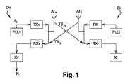
車両Vは、第1の送受信デバイスDvを備え、識別子Iは、第2の送受信デバイスDiを備える。第1の送受信デバイスDv及び第2の送受信デバイスDiは、同様のものであり、以下では一般的な記載が与えられる。 The vehicle V includes a first transmission / reception device Dv, and the identifier I includes a second transmission / reception device Di. The first transmission / reception device Dv and the second transmission / reception device Di are similar, and general descriptions are given below.
図1を参照すると、送受信デバイスDp、インデクスpはv又はiを区別することなく示す、は、
無線信号(少なくとも1GHzに等しい周波数を有する)の送信機TXpと、
無線信号(少なくとも1GHzに等しい周波数を有する)の受信機RXpと、
送信機TXp及び受信機RXpが接続されているアンテナAtpと、
送信機TXpに様々な周波数の信号を供給するための位相同期回路(Phase Locked Loop)PLLpと、
受信機RXpにより受信された信号に基づいて計算を実行するコンピュータXpと、
を備える。Referring to FIG. 1, the transmission / reception device Dp and the index p indicate v or i without distinction.
With the transmitter TXp of the radio signal (having a frequency equal to at least 1 GHz),
The receiver RXp of the radio signal (having a frequency equal to at least 1 GHz) and
The antenna Atp to which the transmitter TXp and the receiver RXp are connected, and
A phase-locked loop PLLp for supplying signals of various frequencies to the transmitter TXp,
Computer Xp, which performs calculations based on the signal received by receiver RXp, and
To prepare for.
スマートフォンは、上記送受信デバイスDpの全ての構成要素をネイティブに有していることに留意されたい。したがって、1つの好ましい実施形態において、識別器Iは、ハンズフリーアクセス及び車両スタートのための好適なアプリケーションを有しているスマートフォンである。送受信デバイスDiの様々な構成要素は、スマートフォンにインストールされた当該アプリケーションにより、有利にトリガされ、かつ、制御される。 It should be noted that the smartphone natively has all the components of the transmission / reception device Dp. Therefore, in one preferred embodiment, the classifier I is a smartphone having suitable applications for hands-free access and vehicle start. Various components of the transmit / receive device Di are advantageously triggered and controlled by the application installed on the smartphone.
本発明に係る方法は、第1の送受信デバイスDv及び第2の送受信デバイスDiにより実装される。第1の送受信デバイスDv及び第2の送受信デバイスDiは、例えば、ブルートゥース(登録商標)ローエナジーのプロトコル(スマートフォンはネイティブにブルートゥースチップを有していることに留意されたい)を介してあらかじめ相互に同期されていることに留意されたい。図2を参照すると、方法METHは、以下のステップを備える。 The method according to the present invention is implemented by the first transmission / reception device Dv and the second transmission / reception device Di. The first transmit / receive device Dv and the second transmit / receive device Di may pre-mutually, for example, via the Bluetooth® Low Energy protocol (note that smartphones natively have a Bluetooth chip). Note that it is synchronized. Referring to FIG. 2, the method METH comprises the following steps.
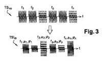
車両Vの送信機TXvから識別器Iの受信機RXiへ、同一の位相及び同一の振幅を有するN個の第1正弦波信号の第1の列TSvpをそれぞれの周波数fp,p∈[1;N]で送信する送信ステップEm_TSvpを備える。第1の列TSvpは、図3に示される。有利には、周波数fpは、N=80、f1=2.4GHz、f80=2.480GHzであり、1〜79の全てのpの値において、fp+1−fp=1MHzである。具体的には、これらの周波数は、ブルートゥースローエナジーのチャネルに対応する。第1の列TSvpは、車両Vの位相同期回路PPLLvにより生成されることに留意されたい。From the transmitter TXv of the vehicle V to the receiver RXi of the classifier I, the first column TSvp of N first sinusoidal signals having the same phase and the same amplitude is set to the respective frequencies fp , p ∈ [. 1; N] is provided witha transmission step Em_TS vp to be transmitted. The first column TSvp is shown in FIG. Advantageously, the frequency fp is N = 80, f1 = 2.4 GHz, f80 = 2.480 GHz, and f p + 1 −fp = 1 MHz forall values of p from 1 to 79. Specifically, these frequencies correspond to the channels of Bluetooth Low Energy. Note that the first column TSvp is generated by the phase-locked loop PPLLv of the vehicle V.
識別器Iの受信機RXiにより、送信ステップEm_TSvpにより変更された第1の列TSvpに対応する第1のイメージ列TSvp’を受信するステップRec_TSvp’を備える。第1のイメージ列TSvp’は、図3に示される。第1のイメージ列TSvp’は、位相φp、振幅ap及び周波数fp,p∈[1;N]をそれぞれ有するN個の正弦波信号Svp’により形成される。初期信号Svpの周波数fpが送信ステップによって変更されていなければ、それらの振幅及びそれらの位相は変更される。具体的には、車両Vの送信機Txvと識別器Iの受信機RXiとの間で信号が受ける反射現象及び屈折現象は、信号の位相をシフトし、振幅を変化させる。The receiver RXi classifier I, comprising the 'steps Rec_TSvp of receiving' first image columnTS vp corresponding to the first rowTS vp changed by transmitting step Em_TSvp. The first image sequence TSvp'is shown in FIG. First image columnTS vp ', the phase phip, amplitudea p and the frequencyf p, p∈ [1; N ] of N sinusoidal signalsS vp with each' are formed by. If the frequency fp of the initial signal Svp has not been changed by the transmission step, their amplitudes and their phase is changed. Specifically, the reflection phenomenon and the refraction phenomenon received by the signal between the transmitter Txv of the vehicle V and the receiver RXi of the classifier I shift the phase of the signal and change the amplitude.
識別器Iの受信機RXiによる、第1のイメージ列TSvp’の信号Svp’の位相φp及び振幅apの計測ステップMes_Datを備える。According to the receiver RXi classifier I, comprising a measurement step Mes_Dat phase phip and amplitudea p 'of signalS vp of' the first image columnTS vp.
前ステップにおける識別器Iにより計測された振幅ap及び位相φpのデータ形成における送信Tr_Datステップを備える。これらのデータは、例えば、ブルートゥースローエナジープロトコルを用いて送信される。A transmission Tr_Dat step in the data form of the measured amplitude ap and phase phip by identifier I in the previous step. These data are transmitted, for example, using the Bluetooth Low Energy Protocol.
識別器Iの送信機TXiから車両Vの受信機RXvへの第1の列TSvpと一致する第2の列TSipの送信ステップEm_TSipを備える。TSipは、識別器の位相同期回路PLLiにより生成されることに留意されたい。A transmission step Em_TSip second rowTS ip that matches the first rowTS vp from the transmitter TXi discriminator I to the receiver RXv vehicle V. Note that the TSip is generated by the phase-locked loop PLLi of the classifier.
車両Vの受信機RXvによる送信ステップEm_TSipにより変化した第2の列TSipに対応する第2のイメージ列TSip’の受信ステップRec_TSip’を備える。Comprises a 'receiving step Rec_TSip' of the second image sequenceTS ip corresponding to the second rowTS ip that has changed by transmitting step Em_TSip by the receiver RXv vehicle V.
車両Vの受信機RXvによる第2のイメージ列TSip’の信号の位相及び振幅の計測ステップを備える。A phase and the measurement step of the amplitude of the second image sequence TS ip'of the signal by the receiver RXv vehicle V.
時刻t4において、以下のステップを備える。
第1のイメージ列TSvp’及び第2のイメージ列TSip’のスペクトル線の検出を介した、第1のイメージ列TSvp’及び第2のイメージ列TSip’の周波数スペクトルの構成ステップCons_Spを備える。
時間シグニチャSgを取得することを可能にする、逆フーリエ変換ステップTFI_Spを備える。時間シグニチャSgは、パルスが第1の列TSvp及び第2の列TSipの代わりに送信されている場合に取得されているであろう時間シグニチャと同等のものである。
時間シグニチャSgの最大値に関連する中間時間tdの決定ステップDet_tdを備える。At timet 4, it comprises the following steps.
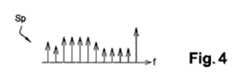
Through the detection of the first image columnTS vp 'and the second image sequenceTS ip' spectral lines, configuration steps of the frequency spectrum of the first image columnTS vp 'and the second image sequenceTS ip' Cons_Sp To prepare for.
It comprises an inverse Fourier transform step TFI_Sp that makes it possible to obtain the time signature Sg. The time signature Sg is equivalent to the time signature that would have been acquired ifthe pulse had been transmitted in place of the first column TS vp and the second column TSip.
The step Det_tdfor determining the intermediate time t d associated with the maximum value of the time signature Sg is provided.
車両VのコンピュータXvによる、以下の式を用いた中間時間tdに基づいた距離Rの計算ステップCal_Rを備える。
計算された距離Rに基づいて、かつ、特定の要求機能(例えば、ドアの開き、ドアの閉め、車両のスタート)に応じて、車両VのコンピュータXvは、機能が実行されるべきかどうかを決定することができる。 Based on the calculated distance R and in response to a particular required function (eg, door open, door close, vehicle start), vehicle V's computer Xv determines whether the function should be performed. Can be decided.
代わりに、中間時間tdは、時間シグニチャの最大ローブの開始の値を探すことにより決定されることが可能である。ローブの開始は、最大値と定数(例えば20dB)との差から決定してもよい。代わりに、ローブの開始は、最大値と、時間シグニチャの最大ローブから最も遠いローブの平均値に応じた値との差により決定される。Alternatively, the intermediate time td may be determined by looking for the value of the start of the maximum lobe time signature. The start of the lobe may be determined by the difference between the maximum value and a constant (eg 20 dB). Instead, the lobe start is determined by the difference between the maximum value and the average value of the lobe farthest from the maximum lobe of the time signature.
当然のことながら、方法のステップは、代替として、上記に示されたものとは別の技術的に実現可能な順序で実行されてもよい。 Of course, the steps of the method may, as an alternative, be performed in a technically feasible order different from that shown above.
Claims (6)
Translated fromJapanese前記方法は、
同一の振幅、及び、規則的な間隔のそれぞれの周波数fp,p∈[1;N]、を有するN個の第1正弦波信号の第1の列(TSvp)の前記車両(V)から前記識別器(I)への送信ステップ(Em_TSvp)と、
識別器(I)により、前記送信ステップにおいて変化させられた第1の列(TSvp)に対応する受信した第1のイメージ列(TSvp’)の信号の位相(φp)及び振幅(ap)の計測ステップ(Mes_Dat)と、
計測された位相(φp)及び振幅(ap)の前記識別器(I)から前記車両(V)への送信ステップ(Tr_Dat)と、
前記第1の列(TSvp)と同一である第2の列(TSip)の前記識別器(I)から前記車両(V)への送信ステップ(Em_TSip)と、
前記第1のイメージ列(TSvp’)、及び、前記送信ステップにより変化させられた前記第2の列(TSip)に対応する第2のイメージ列(TSip’)の周波数スペクトル(Sp)の構成ステップ(Cons_Sp)と、
時間シグニチャ(Sg)を取得することを可能にする、逆フーリエ変換ステップ(TFI_Sp)と、
時間シグニチャ(Sg)の最大値に関連する中間時間(td)の決定ステップ(Det_td)と、
前記中間時間(td)に基づく前記距離(R)の計算ステップ(Cal_R)と、
を備える計測方法。A method (METH) for measuring a distance (R) that separates a vehicle (V) from a classifier (I) for accessing the vehicle (V) and starting the vehicle (V). The vehicle (V) and the classifier (I) are synchronized with each other.
The method is
The vehicle (V) inthe first row (TS vp ) of N first sinusoidal signals with the same amplitude and the respective frequencies fp , p ∈ [1; N], at regular intervals. To the classifier (I) from the transmission step (Em_TSvp ) and
The identifier (I), the first row(TS vp) first image sequence received corresponding to(TS vp ') of the signal of the phase (phip) and amplitude (a which is varied in said transmission step The measurement step (Mes_Dat) ofp) and
A step (Tr_Dat) of transmitting the measured phase (φp ) and amplitude (ap ) from the classifier (I) to the vehicle (V), and
The transmission step (Em_TS ip ) from the classifier (I) to the vehicle (V) in the second column (TSip ) which is the same as the first column (TSvp).
The frequency spectrum (Sp) of the first image sequence (TSvp ') and the second image sequence (TSip') corresponding to the second column (TS ip ) changed by the transmission step. Configuration step (Cons_Sp) and
An inverse Fourier transform step (TFI_Sp) that makes it possible to obtain a time signature (Sg),
An intermediate time (t d ) determination step (Det_td ) associated with the maximum time signature (Sg), and
The calculation step (Cal_R) of the distance (R) based on the intermediate time (td), and
Measurementhow with a.
Applications Claiming Priority (3)
| Application Number | Priority Date | Filing Date | Title |
|---|---|---|---|
| FR1558833AFR3041459B1 (en) | 2015-09-18 | 2015-09-18 | METHOD FOR DETERMINING A DISTANCE BETWEEN A VEHICLE AND AN IDENTIFIER |
| FR1558833 | 2015-09-18 | ||
| PCT/EP2016/072061WO2017046386A1 (en) | 2015-09-18 | 2016-09-16 | Method for determining a distance between a vehicle and an identifier |
Publications (2)
| Publication Number | Publication Date |
|---|---|
| JP2018533001A JP2018533001A (en) | 2018-11-08 |
| JP6968784B2true JP6968784B2 (en) | 2021-11-17 |
Family
ID=55486748
Family Applications (1)
| Application Number | Title | Priority Date | Filing Date |
|---|---|---|---|
| JP2018514307AActiveJP6968784B2 (en) | 2015-09-18 | 2016-09-16 | How to determine the distance between the vehicle and the classifier |
Country Status (6)
| Country | Link |
|---|---|
| US (1) | US10712439B2 (en) |
| EP (1) | EP3350619B1 (en) |
| JP (1) | JP6968784B2 (en) |
| CN (1) | CN108780146B (en) |
| FR (1) | FR3041459B1 (en) |
| WO (1) | WO2017046386A1 (en) |
Families Citing this family (2)
| Publication number | Priority date | Publication date | Assignee | Title |
|---|---|---|---|---|
| US10984615B2 (en)* | 2018-10-12 | 2021-04-20 | Denso International America, Inc. | Passive entry/passive start access systems with tone exchange sniffing |
| JPWO2022038890A1 (en)* | 2020-08-17 | 2022-02-24 |
Family Cites Families (25)
| Publication number | Priority date | Publication date | Assignee | Title |
|---|---|---|---|---|
| US5293160A (en)* | 1989-11-02 | 1994-03-08 | Nissan Motor Company, Ltd. | Keyless vehicle lock system with distance measuring |
| JP3572391B2 (en)* | 1999-08-04 | 2004-09-29 | 日産自動車株式会社 | Distance measuring device |
| JP2004502177A (en)* | 2000-06-27 | 2004-01-22 | シーメンス アクチエンゲゼルシヤフト | Method for measuring the distance between two objects, and for controlling access control to an object or for controlling the use of an object, especially an access control and travel authentication device for a motor vehicle |
| AU2002214159B2 (en)* | 2000-11-15 | 2006-09-07 | Turftrax Group Limited | Tag tracking |
| JP3935432B2 (en)* | 2000-12-29 | 2007-06-20 | シーメンス アクチエンゲゼルシヤフト | Identification system for certifying authority for access to objects or use of objects, especially cars |
| US6731908B2 (en)* | 2001-01-16 | 2004-05-04 | Bluesoft, Inc. | Distance measurement using half-duplex RF techniques |
| JP5440893B2 (en)* | 2005-03-09 | 2014-03-12 | オムロン株式会社 | Information processing apparatus, information processing method, reflector, and communication system |
| JP4270299B2 (en)* | 2006-03-28 | 2009-05-27 | オムロン株式会社 | RFID tag distance measuring device and RFID tag distance measuring system |
| JP4950537B2 (en)* | 2006-03-31 | 2012-06-13 | セコム株式会社 | Moving object detection device |
| JP4670777B2 (en)* | 2006-09-06 | 2011-04-13 | 株式会社デンソー | Vehicle control system |
| JP2008145425A (en)* | 2006-11-13 | 2008-06-26 | Toyota Central R&D Labs Inc | Radar equipment |
| JP4994023B2 (en)* | 2006-12-25 | 2012-08-08 | 富士重工業株式会社 | Pulse radar, automotive radar and landing assist radar |
| JP2008199411A (en)* | 2007-02-14 | 2008-08-28 | Omron Corp | Frequency switcher, rfid system and distance measuring apparatus incorporating the frequency switcher |
| DE102008007842B3 (en)* | 2008-02-07 | 2009-11-05 | Continental Automotive Gmbh | Synchronization of the communication between the identification transmitter and the vehicle station of an access device |
| JP5305324B2 (en)* | 2008-03-11 | 2013-10-02 | 大学共同利用機関法人情報・システム研究機構 | Distance measuring method, distance measuring receiving station apparatus and position measuring system |
| US8279112B2 (en)* | 2008-11-03 | 2012-10-02 | Trimble Navigation Limited | Methods and apparatuses for RFID tag range determination |
| DE102009060591A1 (en)* | 2008-12-30 | 2010-07-08 | Atmel Automotive Gmbh | Transmitter-receiver circuit and method for distance measurement between a first node and a second node of a radio network |
| DE102009060593A1 (en)* | 2008-12-30 | 2010-07-08 | Atmel Automotive Gmbh | System, method and circuit for distance measurement between two nodes of a radio network |
| CN102594539B (en)* | 2011-01-04 | 2017-03-01 | 上海通用汽车有限公司 | Remote-control keyless entry system for vehicle |
| IT1404537B1 (en)* | 2011-02-25 | 2013-11-22 | Sisvel Technology Srl | METHOD FOR ESTIMATING THE DISTANCE OF A RECEIVER FROM A RADIO TRANSMITTER, RELATED METHODS FOR CALCULATING THE POSITION OF A MOBILE TERMINAL, MOBILE TERMINAL AND DEVICE. |
| US9184598B2 (en)* | 2011-10-26 | 2015-11-10 | Leggett & Platt Canada Co. | Signal discrimination for wireless key fobs and interacting systems |
| EP2932740B1 (en)* | 2012-12-12 | 2020-04-29 | PoLTE Corporation | Multi-path mitigation in rangefinding and tracking objects using reduced attenuation rf technology |
| CN203142623U (en)* | 2013-03-21 | 2013-08-21 | 长春亚美电子技术有限公司 | Automobile passive key recognition system |
| US9131347B2 (en)* | 2013-04-26 | 2015-09-08 | Qualcomm Incorporated | Utilizing a pressure profile to determine a location context identifier |
| EP3306576B1 (en)* | 2016-10-05 | 2023-03-15 | The Swatch Group Research and Development Ltd | Method and system for secure access to a determined space by means of a portable object |
- 2015
- 2015-09-18FRFR1558833Apatent/FR3041459B1/ennot_activeExpired - Fee Related
- 2016
- 2016-09-16EPEP16769963.6Apatent/EP3350619B1/enactiveActive
- 2016-09-16CNCN201680060833.4Apatent/CN108780146B/enactiveActive
- 2016-09-16JPJP2018514307Apatent/JP6968784B2/enactiveActive
- 2016-09-16USUS15/759,975patent/US10712439B2/enactiveActive
- 2016-09-16WOPCT/EP2016/072061patent/WO2017046386A1/ennot_activeCeased
Also Published As
| Publication number | Publication date |
|---|---|
| FR3041459B1 (en) | 2017-10-13 |
| CN108780146B (en) | 2022-06-28 |
| JP2018533001A (en) | 2018-11-08 |
| WO2017046386A1 (en) | 2017-03-23 |
| EP3350619A1 (en) | 2018-07-25 |
| EP3350619B1 (en) | 2019-12-04 |
| CN108780146A (en) | 2018-11-09 |
| US20180252805A1 (en) | 2018-09-06 |
| US10712439B2 (en) | 2020-07-14 |
| FR3041459A1 (en) | 2017-03-24 |
Similar Documents
| Publication | Publication Date | Title |
|---|---|---|
| CN114342418B (en) | Multiplexed antenna circuit network for UHF low energy based phones as keys for accessing vehicles | |
| JP6334311B2 (en) | Distance measuring system | |
| CN111512175B (en) | Method for checking the dependence of a radio node on the radio environment of an object | |
| CN109118613B (en) | Method for operating a radio-based passive locking device of a motor vehicle and such a locking device | |
| KR20170125739A (en) | Method using ultra high frequency waves for locating a portable device giving “hands free” access to a vehicle, associated locating device and portable device | |
| WO2014140185A1 (en) | Method and device for issuing an access authorization | |
| JP7142728B2 (en) | METHOD FOR DETERMINING RELAY ATTACK, RELAY ATTACK DETECTION DEVICE AND COMPUTER PROGRAM | |
| US10677913B2 (en) | Method for determining a distance between a vehicle and a vehicle access and starter identifier | |
| US20230184916A1 (en) | Ultra-wide band test system | |
| US10809371B2 (en) | Method for determining a distance between a vehicle and a vehicle access and starter identifier | |
| JP6968784B2 (en) | How to determine the distance between the vehicle and the classifier | |
| JP2021128080A (en) | Communication device, information processing method, and program | |
| JP7286345B2 (en) | Position detection system | |
| JP6654258B2 (en) | Authentication system, portable device, registration method, and program | |
| CN118692176A (en) | A digital key unlocking and locking judgment method and intelligent door lock system based on UWB | |
| JP6968783B2 (en) | How to help determine the location of the classifier associated with the vehicle | |
| WO2020013137A1 (en) | Half-hemisphere antennas for locating remote devices | |
| JP2021128079A (en) | Communication device, control method, and program | |
| FR3120939A1 (en) | METHOD FOR DETERMINING THE POSITION OF PORTABLE EQUIPMENT IN RELATION TO A MOTOR VEHICLE AND ASSOCIATED PORTABLE EQUIPMENT | |
| JP2017145557A (en) | Unauthorized communication establishment prevention system and electronic key system | |
| US20250067861A1 (en) | Method for activating a vehicle function and associated activation device | |
| CN117098132A (en) | Security enhancement for multi-user ranging systems using characteristic orthogonal chirps | |
| JP2025126140A (en) | Access control method for resolving context ambiguity and device using same |
Legal Events
| Date | Code | Title | Description |
|---|---|---|---|
| A621 | Written request for application examination | Free format text:JAPANESE INTERMEDIATE CODE: A621 Effective date:20190911 | |
| A977 | Report on retrieval | Free format text:JAPANESE INTERMEDIATE CODE: A971007 Effective date:20200916 | |
| A131 | Notification of reasons for refusal | Free format text:JAPANESE INTERMEDIATE CODE: A131 Effective date:20201020 | |
| A521 | Request for written amendment filed | Free format text:JAPANESE INTERMEDIATE CODE: A523 Effective date:20210106 | |
| A131 | Notification of reasons for refusal | Free format text:JAPANESE INTERMEDIATE CODE: A131 Effective date:20210326 | |
| A521 | Request for written amendment filed | Free format text:JAPANESE INTERMEDIATE CODE: A523 Effective date:20210615 | |
| TRDD | Decision of grant or rejection written | ||
| A01 | Written decision to grant a patent or to grant a registration (utility model) | Free format text:JAPANESE INTERMEDIATE CODE: A01 Effective date:20211001 | |
| A61 | First payment of annual fees (during grant procedure) | Free format text:JAPANESE INTERMEDIATE CODE: A61 Effective date:20211027 | |
| R150 | Certificate of patent or registration of utility model | Ref document number:6968784 Country of ref document:JP Free format text:JAPANESE INTERMEDIATE CODE: R150 | |
| R250 | Receipt of annual fees | Free format text:JAPANESE INTERMEDIATE CODE: R250 |